helios expertise in aerodynamics. axial fans without limits
TRANSCRIPT

Helios expertise in aerodynamics.Axial fans without limits.
High-performance axial and medium-pressure ventilatorsRADAX® VAR high-pressure in-line fans
138
As one of the leading Euro-pean fan manufacturers,Helios impresses with ex-traordinarily large, finelygraduated range of high-performance axial, medium-pressure and RADAX® VARhigh-pressure fans in all per-formance ranges.
The next pages present therange for high-performanceaxial fans with aerodynamicand acoustically optimised im-peller and an innovative motorconcept (diameter of 250 to500 mm).
The particularly energy-savingEC models achieve energysavings of over 55% in com-parison to conventional ACtypes thanks to their speedcontrols.The AC high-performance axialfans with diameters of 250 to500 mm and voltage controlhave an impressive, tried-and-tested and robust design andincrease efficiency by 25%while reducing noise by 50%.
The range with diameters of upto 1000 mm is supplementedby solutions for the area oftechnical building equipment(TGA), see the right hand side.
� Fire gases and smoke ex-traction types in accordancewith DIN 12101-3 in temper-ature classes F300 (60 min-utes), F400 (120 minutes)and F600 (120 minutes).See separate catalogue.
� Specialist solutions for tech-nical building equipment(TGA) and large axial fanswith diameters from 1000 to7100 mm, volumes of up to2.2 million m³/h can be pro-duced in accordance withcustomer-specific require-ments.See www.AxialSoft.de forthe design.

Well-known users from allover the world trust Heliosaxial fans for ventilation,heating, cooling and dryingapplications. Large fanshave been used successfullyfor decades e.g. in coolingtowers and condensers.
HIGH-PERFORMANCEAXIAL FANSProduct-specific informationand selection chart
INSTALLATIONACCESSORIESFor axial and RADAX® VARin-line fans
Energy-efficient EC version Ø 250 – 500 mmV.= 1930 – 8300 m³/h
StandardAC version Ø 200 – 1000 mmV.= 520 – 63 420 m³/h
MEDIUM PRESSUREAXIAL FANSProduct-specific informationand selection chart
RADAX® VARHIGH-PRESSURE FANS Product-specific informationand selection chart
Ø 225 – 630 mmV.= 950 – 26 450 m³/h
Ø 225 – 630 mmV.= 900 – 22 310 m³/h
140
231on
142on 154on
180on 206on
High-performance and medium pressure axial fansRADAX® VAR high-pressure in-line fans
139
Axia
l and
VAR
fans

Axial fansProduct-specific information
140
Air flow direction Apulling air over the motor
Air flow direction Bpushing air over the motor
The following information com-pletes the “General TechnicalInformation” section.
� Types� Helios offer a wide range ofproducts for various applica-tions, i.e. particular help forproblem solutions.
� Standard and high-performancefans in indu strial design areavailable as standard in morethan 20 standard sizes andmore than 1000 types; many ofwhich are shown in this cata-logue.
� Closely matched air flow volumeand pressure can be achievedon larger fans with a maximumdiameter of 7100 mm throughadjustable pitch angle. Fourstandard casing types are avail-able.
� Types HQ, HW and HRF areavailable up to standard size500 mm with highly-efficient ECmotor technology for particularlyenergy-saving application andlowest operating costs.
� Types in this catalogue1. Wall fan HQSquare plate with inlet coneCasing made from galvanisedsheet steel. Motor with terminalbox and motor side guard.
2. Built-in fansHW, AVD DKCircular plate with inlet coneCasing made from galvanisedsheet steel. Motor with terminalbox and motor side guard.
3. Built-in wall fan HSCylindrical duct case withspigot endsFor flush, wall or in-line duct in-stallation. Casing made from gal-vanised sheet steel with circularstiffening rings.
4. In-line fansHRF, AVD RKCylindrical duct with flangeson both endsFor direct in-line installation inducting. Flanges made to DIN24155, PT. 3. Casing made fromgalvanised sheet steel, addition-al terminal box (IP 55) on outercasing.
� Motor� AC typesRobust 1 ph. or 3 ph. internalrotor motor with thermal con-tacts in the windings. Ball bear-ings lubricated for life.
� EC typesHighly-efficient, speed control-lable external rotor motor pro-tected to IP 44 or 54. Ball bear-ings lubricated for life.
� Impellers� Depending on the performancerequirements the impellers aremade from various materials;see product pages. The stan-dard design is made from rein-forced polymers. Other materi-als, aluminium or steel, are avail-able on special order.
� All impellers feature:– Low noise characteristics.– High efficiency.– Vibration free operation due tody na mic balancing to DIN ISO1940 T.1 – grade 6.3.
� Impellers made from other ma-terials are available upon re-quest.
� The standard models are suit-able for air flow temperaturefrom –30° to +60 °C. For highertemperatures metal impellers areavailable to order. See informa-tion on the product pages.
� Pitch angle� The standard products up to 630mm Ø are equipped with fixedimpeller blades.
� Starting from nominal size 710mm (except type HQW 710/6),the impeller blades are availablewith order related pitch angles.
� The installation sizes Ø 800/4,900/4 and ../6 as well asØ 1000 mm have adjustableblades at standstill.This enables the fan to providethe exact duty required. Thepitch angle is factory set (mustbe stated when ordering). Themotors are selected using theirmaximum performance (seetable on product page). Themaximum pitch angle shownmust not be exceeded as themotor will be overloaded.
� Air flow directionAll fans (except HRF and AVDRK) come with the air flowdirectionA = pulling air over the motoras standard. Air flow directionB = pushing air over the mo-tor is available for most modelswith an additional charge.HRF and AVD RK come with airflow direction B as standard.
� The air flow direction can bechanged after supply, should itbe required, for most AC high-performance axial fans. To do soyou have to:
1. Change the direction of rotationof the motor by changing theterminals on the terminal board.
2. Remove impeller and put it theopposite way round on the shaft(possible up to Ø 500).Models HQ and HW allow for a1/3 drop in performance.
� EC types can only be operatedin the set standard direction ofrotation.
� Protection against contactAll relevant safety instructionsand regulations must be fol-lowed when the fans are in-stalled. A protection against ac-cidental contact to VDE 0700and/or DIN EN ISO 13857 mustbe guaranteed. The contact withrotating parts must be avoided.Make sure that there are noitems near the inlet which couldbe pulled into the fan. Fanswhich are protected when in-stalled (e.g. in ventilation ductingor closed aggregate) do not re-quire a guard if the system pro-vides sufficient safety. We em-phasise that the installer is re-sponsible for the safety of theinstallation by fitting appropriateprotection devices. Suitableguards are available as acces-sories. The responsibility that allrelevant regulations have beenobserved remains with the in-staller.
� Position, installation,drainage holes
� Axial fans are suitable for instal-lation in any position. If conden-sation is to be expected, (e.g.for intermitting operation, highhumidity air flow or rapidlychanging temperatures) the fanmust be installed with the motordrainage holes facing downwardand they must be open.
� If installed outdoors, or in wetconditions or if installed with themotor shaft facing vertically up-wards, this must be statedwhen ordering. Please makesure that the fan is fixed secure-ly and the casing is notsqueezed or distorted.
� Reverse operationMost axial fans are reversible(see product page). Using a suit-able reversing switch. The fancan be used for intake or ex-tract. In abnormal direction offlow the capacity decreases byapprox. 1/3.
� EC types are not reversible asstandard.
� Air flow temperaturesThe standard models are suit-able for temperatures from–30 °C to +40 °C or +60 °C(AC or EC types).Apart from explosion proof fans,higher temperatures are possiblefor a short time. For permanent-ly higher temperatures specialmodels are available on request.
� Motor protection� For AC types; through thermalcontacts in the windings
– standard for 1 ph. motors,– mostly standard for 3 ph.motors (see product page).
� For EC types; integrated electro-nic temperature monitoring.
� Explosion protectionThe ex-proof models conform tocluster II, category 2G for opera-tion in zone 1 or 2.According to directive2014/34/EU (ATEX), larger airgaps are specified which lead toa capacity reduction of up to10%.
� Extra equipment,additional charge on demand
� Aluminium cast impeller� Alternative voltage� Alternative frequency� Two pack coating for protec-tion of external componentsagainst diluted acids and limesolutions
� Alternative air flow direction� Extra equipment for higher airflow temperatures
� Pressure-tight encapsulatedmotors (standard for 1 ph. ex-proof types)
� Anti vibration insulationTo avoid vibration transmissionto building and ducting the useof anti vibration mounts (acces-sory SDD, SDZ) is highly recom-mended. Larger frame size mo-tors may protrude out of thecasing and might move the cen-tre of gravity within the fan.To avoid an uneven load on theanti vibration mounts, an exten-sion duct is recommended(accessory VR).

2800 78 11050 10960 10870 10770 10680 10590 10500 10310 10130 9950 9770 9580 9210 8690 8050 6930 4520
1440 80 63420 63030 62650 62260 61870 61490 61110 60330 59560 58790 58010 57240 55700 53710 51590 49260 46830
950 69 41740 41150 40570 39990 39400 38810 38230 37060 35870 34610 33260 31810 28880
725 62 31760 30990 30220 29460 28690 27930 27130 25410 23500 21540
1435 76 46060 45700 45390 45030 44670 44310 44000 43280 42600 41880 41170 40800 39060 37110 34940 32800 30340
950 66 30500 30100 29500 29100 28500 27900 27400 26300 25100 23910 22710 21310
725 59 21160 20410 19640 18850 18010 17120 16130 15000
1435 73 32350 32040 31720 31400 31090 30770 30490 29860 29230 28610 27990 27330 25940 24020 22080
945 62 20720 20280 19830 19350 18850 18290 17710 16530 15330 13840 10740
705 55 15380 14780 14120 13380 12580 11790 10900
1450 71 23740 23490 23240 22980 22730 22470 22200 21660 21090 20500 19900 19290 18010 16240 14000 11060
935 61 15250 14860 14450 14040 13590 13140 12600 11690 10610 9280 7440
700 54 11350 10810 10250 9630 8990 8300 7500 5340
2800 81 13150 13040 12930 12820 12720 12610 12500 12290 12070 11860 11660 11440 11010 10380 9600 8620 5390
1450 65 17870 17650 17420 17200 16970 16750 16520 16010 15500 15000 14500 14000 13000 11300
950 55 10520 10150 9780 9410 9040 8670 8220 7260
725 49 8000 7580 7010 6530 5910 5300
560
560
560
500
500
500
450
450
450
450
400
400
400
400
355
355
355
355
315
315
315
315
250
250
250
200
200
mm
Diameter
min-1 LPA dB(A) (DPfa) in Pa
2300 55 910 860 810 760 710 490 420 330 220
1360 42 520 410 210 170
2800 53 2070 2040 2010 1970 1940 1910 1870 1800 1710 1610 1480
1450 44 930 840 730
950 31 660 570
2800 69 4090 4050 4020 3990 3950 3920 3880 3790 3700 3610 3500 3380 3090
1450 51 2090 2010 1930 1840 1740 1620 1410
950 38 1330 1220 1070
725 30 980 780
2800 71 5710 5670 5620 5580 5530 5480 5430 5330 5220 5110 4990 4860 4550 4020
1450 51 2850 2770 2670 2570 2450 2320 2160
950 42 1940 1830 1690 1500 1060
725 34 1430 1240 880
2800 71 8410 8360 8310 8270 8220 8170 8130 8030 7940 7840 7750 7650 7440 7160 6840 6440 5820
1450 56 4010 3920 3810 3700 3580 3440 3300 2970
950 45 2570 2410 2230 2020
725 37 2010 1810 1530
1450 58 5770 5680 5590 5500 5390 5280 5160 4870 4510 4010
950 47 3890 3720 3550 3360 3150 2890
725 51 2860 2680 2450 2120
1450 65 8320 8220 8110 8000 7880 7760 7630 7370 7080 6760 6400 5970
950 51 5500 5330 5140 4950 4740 4510 4240 3450
725 44 3890 3690 3440 3150 2750
1450 62 12910 12680 12550 12360 12140 11950 11770 11320 10900 10550 10000 9500 8270
950 52 8100 7680 7370 7080 6680 6280 5830 4570
725 46 6450 6070 5640 5230 4750 4140
in 4 m 0 10 20 30 40 50 60 80 100 120 140 160 200 250 300 350 400
R.P.M. Sound press. Air flow volume V.m3/h depending on static pressure
Intake
900
900
900
1000
1000
1000
800
800
800
500
710
710
710
630
630
630
Selection chartHigh-performance axial fans
141
Axia
l and
VAR
fans
By combining the parameters of static pressure increase Dpfa, air flowvolume V
., speed min-1, sound pressure level dB(A) and impeller diameter
DN mm, the following table facilitates the selection of EC high-performance
axial fans Ø 250 to 500 mm and high-performance axial fans Ø 200 to1000 mm.
EC 250 2300 56 1930 1880 1820 1760 1700 1630 1550 1370 1070
EC 400 A
EC 355 B
EC 355 A
EC 315 1650 52 3110 3000 2880 2760 2640 2520 2400 2090 1680
1200 50 3220 3050 2870 2700 2520 2330 2090
1975 59 4200 4150 4090 4020 3960 3890 3820 3690 3540 3360 3100 2790
1800 59 4790 4690 4610 4540 4460 4390 4310 4140 3920 3640 3240
EC 400 B 2150 65 5850 5800 5760 5700 5640 5560 5490 5360 5210 5080 4870 4730 4030
EC 450 A 1325 55 5460 5350 5250 5140 5030 4910 4790 4520 4200 3730
EC 450 B 1835 64 7640 7580 7510 7450 7390 7330 7260 7070 6880 6680 6490 6200 5530
EC 500 A 1025 54 6320 6190 6050 5900 5750 5590 5420 5010 4460
EC 500 B 1450 62 8300 8230 8150 8070 7970 7880 7790 7490 7300 6910 6530 6140
mm
Diameter
min-1 LPA dB(A) (DPfa) in Pa
in 4 m 0 10 20 30 40 50 60 80 100 120 140 160 200 250 300 350 400
R.P.M. Sound press. Air flow volume V.m3/h depending on static pressure
Intake

Ref. no.
4823
142
250 mm ø EC high-performance axial fans
4822 10462650 1930 0.97 56 40 6.5 4824HRFW EC 250 AHQW EC 250 A0.13
� Specification for all types� CasingManufactured in galvanisedsheet steel. Models HQ and HWhave the additional protection oftwo coats of papyrus white.
� ImpellerHighly efficient with profiled poly-mer blades, aerodynamicallyoptmised for application, dy-namically balanced. Operatingrange from –30 to +60 °C.
� MotorEnergy-saving, speed-control-lable EC external rotor motorprotected to IP 44 with high lev-el of efficiency. Maintenance-freeand interference-free, excellentelectromagnetic compatibility(EMC), ball bearing mounted.
� Motor protectionIntegrated electronic tempera-ture monitoring for EC motorand electronics.
� Electrical connectionStandard terminal box (protec-tion to IP 54) mounted to run-ning cable and on the outside ofthe ducting for HRF.
� GuardMade from powder-coated steelfor HQ and HW, in accordancewith DIN EN ISO 13857.
� Speed controlAll types are steplessly control-lable through the speed-poten-tiometer. Furthermore, control isalso possible via three-stepswitch or steplessly via universalcontrol system or electronic dif-ferential pressure/temperaturecontroller. See table below. theexample performance stagesare shown in the characteristiccurves.
R.P.M. Motorpower
Air flowvolume(FID)
Current Wiringdiagram
No.
max. air flowtemperature
Weightnet
approx. Ref. no.HQ ECincl.guard
HW ECincl.guard
Ref. no.HRF EC
Type
min-1 kWV· m3/h A +°C kg
� InstallationInstallation in any position.
� Sound levelsSum levels and spectrum figuresfor sound power and soundpressure levels in 4 m free fieldconditions are specified abovethe characteristic curve for amedium intake/exhaust opera-ting point. The sound pressuresum level in 4 m (free field con-ditions) is also shown in thetable below and the table belowthe characteristic curve for dif-ferent voltages.Sound emissions and roomacoustics see page 10.
HQ EC HW EC HRF EC
All dim. in mm
Soundpressure
dB(A) in 4 m
1 ph. motor, 1~ 230 Volt, 50/60 Hz, EC motor, protection to IP 44
HWW EC 250 A
Air flow direction Air flow direction Air flow direction
Saving ** with speed control

Electronic diff. pressurecontroller/switch
Electronic tem peraturecontroller/switch
Ref. no.Type
1437 EDR 1)
Ref. no.Type
1438 ETR 1)
Three-step speed switch flush surface
Ref. no.Type
4266 SU-3 10 1)
Ref. no.Type
4267 SA-3 10 1)
143
EC high-performance axial fans 250 mm ø
EC A
xial
fans
Accessories for HRF EC Description see page 231 on
Universalcontrol system
Ref. no. Type
1347 EUR EC 1)
Speed-potentiometerflush surface
Ref. no.Type
1734PU 10 1)
Ref. no.Type
1735PA 10 1)
Bell mouth +guardASD-SGD 250No. 1414
Flangedflex. con-nectorSTS 250No. 1220
Automatic back-draught shutterRVS 250 a)
No. 2592
CircularattenuatorRSD 250/..
Extension ductVR 250No. 1402
Counter-flangeFR 250No. 1203
FlexiblesleeveFM 250No. 1672
GuardSG 250No. 1236
2 mounting feet1 x MK 250(= 2 pcs.)No. 1447
4 anti-vibration mounts for sus-pension1 x SDZ 1 (= 4 pcs.) No. 14544 anti-vibration mounts forcompression1 x SDD 1 (= 4 pcs.) No. 1452
SDZ 1
SDD 1
a) Motorised backdraught shutter see Accessories product pages
Frequency Hz Total 125 250 500 1k 2k 4k 8k LWA Air noise dB(A) 76 47 67 70 69 70 67 60 LPA, 4 m Air noise dB(A) 56 27 46 50 49 50 47 40
250 A
DpfaPa
�
�
�
�
�
V· m3/h
r = 1,20 kg/m3
� Information PageTechn. description 140Selection chart 141Information for planning 10 on
Made to order designsAlternative voltages, protection classes, air flow direction, air flow temperature, acid protection and cast aluminium impellers are available on request.
Note the technical information on page 15 on.
FlatflangeFF 250No. 4941
Voltage V n min-1 Free discharge V· m3/h Pel (W) IMotor (A) LPA, 4 m 10 2650 1930 127 0,97 56 8 2230 1620 77 0,62 52 6 1670 1200 40 0,30 46 4 1090 770 15 0,14 37
� Other accessories PageFilters and attenuators 421 onBackdraught shuttersand grilles 487 onUniversal control system,electronic controller,speed-potentiometer 539 on
1) Several EC fans can normally be connected, see Accessories
� 10 V� 8 V� 6 V� 4 V� 2 V

4881
Ref. no.
144
315 mm ø EC high-performance axial fans
� Specification for all types� CasingManufactured in galvanisedsheet steel. Models HQ and HWhave the additional protection oftwo coats of papyrus white.
� ImpellerHighly efficient with profiled poly-mer blades, aerodynamicallyoptmised for application, dy-namically balanced. Operatingrange from –30 to +60 °C.
� MotorEnergy-saving, speed-control-lable EC external rotor motorprotected to IP 44 with high lev-el of efficiency. Maintenance-freeand interference-free, excellentelectromagnetic compatibility(EMC), ball bearing mounted.
� Motor protectionIntegrated electronic tempera-ture monitoring for EC motorand electronics.
� Electrical connectionStandard terminal box (protec-tion to IP 54) mounted to run-ning cable and on the outside ofthe ducting for HRF.
� GuardMade from powder-coated steelfor HQ and HW, in accordancewith DIN EN ISO 13857.
� Speed controlAll types are steplessly control-lable through the speed-poten-tiometer. Furthermore, control isalso possible via three-stepswitch or steplessly via universalcontrol system or electronic dif-ferential pressure/temperaturecontroller. See table below. theexample performance stagesare shown in the characteristiccurves.
� InstallationInstallation in any position.
� Sound levelsSum levels and spectrum figuresfor sound power and soundpressure levels in 4 m free fieldconditions are specified abovethe characteristic curve for amedium intake/exhaust opera-ting point. The sound pressuresum level in 4 m (free field con-ditions) is also shown in thetable below and the table belowthe characteristic curve for dif-ferent voltages.Sound emissions and roomacoustics see page 10.
All dim. in mm
4880 10462040 3110 1.50 52 40 8.0 HWW EC 315 A 4882HRFW EC 315 AHQW EC 315 A0.19
R.P.M. Motorpower
Air flowvolume(FID)
Current Wiringdiagram
No.
max. air flowtemperature
Weightnet
approx. Ref. no.HQ ECincl.guard
HW ECincl.guard
Ref. no.HRF EC
Type
min-1 kWV· m3/h A +°C kg
Soundpressure
dB(A) in 4 m
HQ EC HW EC HRF EC
1 ph. motor, 1~ 230 Volt, 50/60 Hz, EC motor, protection to IP 44
Air flow direction Air flow direction Air flow direction
Saving ** with speed control

145
EC high-performance axial fans 315 mm ø
EC A
xial
fans
Accessories for HRF EC Description see page 231 on
a) Motorised backdraught shutter see Accessories product pages
Ref. no.Type
1437 EDR 1)
Ref. no.Type
1438 ETR 1)
Three-step speed switch flush surface
Ref. no.Type
4266 SU-3 10 1)
Ref. no.Type
4267 SA-3 10 1)
Universalcontrol system
Ref. no. Type
1347 EUR EC 1)
Speed-potentiometerflush surface
Ref. no.Type
1734PU 10 1)
Ref. no.Type
1735PA 10 1)
1) Several EC fans can normally be connected, see Accessories
Electronic diff. pressurecontroller/switch
Electronic tem peraturecontroller/switch
Bell mouth +guardASD-SGD 315No. 1416
Extension ductVR 315No. 1404
CircularattenuatorRSD 315/..
Flangedflex. con-nectorSTS 315 b)
No. 1221
Counter-flangeFR 315No. 1204
FlexiblesleeveFM 315 b)
No. 1674
GuardSG 315No. 1237
Mounting feetMK 315 (1 set = 2 pcs.)No. 1448
Mounting ring forvertical installationMRV 315 No. 1755
Automatic back-draught shutterRVS 315 a)
No. 2594
FlatflangeFF 315No. 4943
Frequency Hz Total 125 250 500 1k 2k 4k 8k LWA Air noise dB(A) 72 44 65 66 67 65 60 51 LPA, 4 m Air noise dB(A) 52 24 45 46 47 45 40 31
315 A
DpfaPa
�
�
�
�
�
V· m3/h
r = 1,20 kg/m3
Voltage V n min-1 Free discharge V· m3/h Pel (W) IMotor (A) LPA, 4 m 10 2040 3110 190 1,5 52 8 1670 2570 110 0,9 48 6 1240 1880 50 0,4 42 4 845 1240 20 0,2 34
� 10 V� 8 V� 6 V� 4 V� 2 V
� Information PageTechn. description 140Selection chart 141Information for planning 10 on
Made to order designsAlternative voltages, protection classes, air flow direction, air flow temperature, acid protection and cast aluminium impellers are available on request.
Note the technical information on page 15 on.
� Other accessories PageFilters and attenuators 421 onBackdraught shuttersand grilles 487 onUniversal control system,electronic controller,speed-potentiometer 539 on

49204919
4916
10471980 4200 1.40 59 40 12.0 HWW EC 355 B 4921HRFW EC 355 BHQW EC 355 B0.32
146
355 mm ø EC high-performance axial fans
� Specification for all types� CasingManufactured in galvanisedsheet steel. Models HQ and HWhave the additional protection oftwo coats of papyrus white.
� ImpellerHighly efficient with profiled poly-mer blades, aerodynamicallyoptmised for application, dy-namically balanced. Operatingrange from –30 to +60 °C.
� MotorEnergy-saving, speed-control-lable EC external rotor motorprotected to IP 44 (type A), IP54 (Type B) with high level of ef-ficiency. Maintenance-free andinterference-free, excellent elec-tromagnetic compatibility (EMC),ball bearing mounted.
� Motor protectionIntegrated electronic tempera-ture monitoring for EC motorand electronics.
� Electrical connectionStandard terminal box (protec-tion to IP 54) For HQ and HWtypes mounted to running cable(“A”) or on the back of the motor(“B”). For HRF types on the out-side of the ducting.
� GuardMade from powder-coated steelfor HQ and HW, in accordancewith DIN EN ISO 13857.
� Speed controlAll types are steplessly control-lable through the speed-poten-tiometer. Furthermore, control isalso possible via three-stepswitch or steplessly via universalcontrol system or electronic dif-ferential pressure/temperaturecontroller. See table below. theexample performance stagesare shown in the characteristiccurves.
� InstallationInstallation in any position.
� Sound levelsSum levels and spectrum figuresfor sound power and soundpressure levels in 4 m free fieldconditions are specified abovethe characteristic curve for amedium intake/exhaust opera-ting point. The sound pressuresum level in 4 m (free field con-ditions) is also shown in thetable below and the table belowthe characteristic curve for dif-ferent voltages.Sound emissions and roomacoustics see page 10.
All dim. in mm HQW EC 355 B
HQ EC HW EC HRF EC
10461500 3220 1.20 50 40 9.0 4917HWW EC 355 A 4918HRFW EC 355 AHQW EC 355 A0.15
R.P.M. Motorpower
Air flowvolume(FID)
Current Wiringdiagram
No.
max. air flowtemperature
Weightnet
approx. Ref. no.HQ ECincl.guard
Ref. no.HW ECincl.guard
Ref. no.HRF EC
Type
min-1 kWV· m3/h A +°C kg
Soundpressure
dB(A) in 4 m
HWW EC 355 B
1 ph. motor, 1~ 230 Volt, 50/60 Hz, EC motor, protection to IP 44
Air flow direction Air flow direction Air flow direction
Saving ** with speed control

1437 EDR 1) 1438 ETR 1)4266 SU-3 10 1) 4267 SA-3 10 1)1347 EUR EC 1) 1734PU 10 1) 1735PA 10 1)
147
EC high-performance axial fans 355 mm ø
EC A
xial
fans
Accessories for HRF EC Description see page 231 on
a) Motorised backdraught shutter see Accessories product pages
Ref. no.Type
1437 EDR 1)
Ref. no.Type
1438 ETR 1)
Three-step speed switch flush surface
Ref. no.Type
4266 SU-3 10 1)
Ref. no.Type
4267 SA-3 10 1)
Universalcontrol system
Ref. no. Type
1347 EUR EC 1)
Speed-potentiometerflush surface
Ref. no.Type
1734PU 10 1)
Ref. no.Type
1735PA 10 1)
1) Several EC fans can normally be connected, see Accessories
Electronic diff. pressurecontroller/switch
Electronic tem peraturecontroller/switch
Bell mouth +guardASD-SGD 355No. 1417
Extension ductVR 355No. 1405
CircularattenuatorRSD 355/..
Flangedflex. con-nectorSTS 355 b)
No. 1222
Counter-flangeFR 355No. 1205
FlexiblesleeveFM 355 b)
No. 1675
GuardSG 355No. 1238
Mounting feetMK 355 (1 set = 2 pcs.)No. 1448
Automatic back-draught shutterRVS 355 a)
No. 2595
FlatflangeFF 355No. 4944
Mounting ring forvertical installationMRV 355 No. 1759
Frequency Hz Total 125 250 500 1k 2k 4k 8k LWA Air noise dB(A) 70 48 61 65 65 63 57 47 LPA, 4 m Air noise dB(A) 50 28 41 45 45 43 37 27
355 A
DpfaPa
�
�
�
�
�
V· m3/h
r = 1,20 kg/m3
Voltage V n min-1 Free discharge V· m3/h Pel (W) IMotor (A) LPA, 4 m 10 1500 3220 146 1,2 50 8 1225 2600 84 0,66 46 6 930 1930 40 0,33 40 4 610 1240 20 0,15 31
� 10 V� 8 V� 6 V � 4 V � 2 V
Frequency Hz Total 125 250 500 1k 2k 4k 8k LWA Air noise dB(A) 79 52 73 73 73 73 67 59 LPA, 4 m Air noise dB(A) 59 32 53 53 53 53 47 39
355 B
DpfaPa
�
�
�
��
V· m3/h
r = 1,20 kg/m3
Voltage V n min-1 Free discharge V· m3/h Pel (W) IMotor (A) LPA, 4 m 10 1980 4200 316 1,4 59 8 1600 3330 175 0,79 54 6 1170 2460 80 0,37 48 4 760 1570 30 0,20 39
� 10 V� 8 V� 6 V� 4 V� 2 V
� Information PageTechn. description 140Selection chart 141Information for planning 10 on
Made to order designsAlternative voltages, protection classes, air flow direction, air flow temperature, acid protection and cast aluminium impellers are available on request.
Note the technical information on page 15 on.
� Other accessories PageFilters and attenuators 421 onBackdraught shuttersand grilles 487 onUniversal control system,electronic controller,speed-potentiometer 539 on

4925 10482150 5850 3.10 65 40 15.4 4926HWW EC 400 B 4927HRFW EC 400 BHQW EC 400 B0.65
148
400 mm ø EC high-performance axial fans
� Specification for all types� CasingManufactured in galvanisedsheet steel. Models HQ and HWhave the additional protection oftwo coats of papyrus white.
� ImpellerHighly efficient with profiled poly-mer blades, aerodynamicallyoptmised for application, dy-namically balanced. Operatingrange from –30 to +60 °C.
� MotorEnergy-saving, speed-control-lable EC external rotor motorprotected to IP 54 with high lev-el of efficiency. Maintenance-freeand interference-free, excellentelectromagnetic compatibility(EMC), ball bearing mounted.
� Motor protectionIntegrated electronic tempera-ture monitoring for EC motorand electronics.
� Electrical connectionStandard terminal box (protec-tion to IP 54) For HQ and HWtypes mounted to running cable(“A”) or on the back of the motor(“B”). For HRF types on the out-side of the ducting.
� GuardMade from powder-coated steelfor HQ and HW, in accordancewith DIN EN ISO 13857.
� Speed controlAll types are steplessly control-lable through the speed-poten-tiometer. Furthermore, control isalso possible via three-stepswitch or steplessly via universalcontrol system or electronic dif-ferential pressure/temperaturecontroller. See table below. theexample performance stagesare shown in the characteristiccurves.
� InstallationInstallation in any position.
� Sound levelsSum levels and spectrum figuresfor sound power and soundpressure levels in 4 m free fieldconditions are specified abovethe characteristic curve for amedium intake/exhaust opera-ting point. The sound pressuresum level in 4 m (free field con-ditions) is also shown in thetable below and the table belowthe characteristic curve for dif-ferent voltages.Sound emissions and roomacoustics see page 10.
All dim. in mm HQW EC 400 B
HQ EC HW EC HRF EC
4922 10471700 4790 1.40 59 40 13.4 4923HWW EC 400 A 4924HRFW EC 400 AHQW EC 400 A0.32
R.P.M. Motorpower
Air flowvolume(FID)
Current Wiringdiagram
No.
max. air flowtemperature
Weightnet
approx. Ref. no.HQ ECincl.guard
Ref. no.HW ECincl.guard
Ref. no.HRF EC
Type
min-1 kWV· m3/h A +°C kg
Soundpressure
dB(A) in 4 m
HWW EC 400 B
1 ph. motor, 1~ 230 Volt, 50/60 Hz, EC motor, protection to IP 54
Air flow directionAir flow directionAir flow direction
Saving ** with speed control

149
EC high-performance axial fans 400 mm ø
EC A
xial
fans
Accessories for HRF EC Description see page 231 on
a) Motorised backdraught shutter see Accessories product pages
1437 EDR 1) 1438 ETR 1)4266 SU-3 10 1) 4267 SA-3 10 1)1347 EUR EC 1) 1734 PU 10 1) 1735 PA 10 1)
Ref. no.Type
1437 EDR 1)
Ref. no.Type
1438 ETR 1)
Three-step speed switch flush surface
Ref. no.Type
4266 SU-3 10 1)
Ref. no.Type
4267 SA-3 10 1)
Universalcontrol system
Ref. no. Type
1347 EUR EC 1)
Speed-potentiometerflush surface
Ref. no.Type
1734 PU 10 1)
Ref. no.Type
1735 PA 10 1)
1) Several EC fans can normally be connected, see Accessories
Electronic diff. pressurecontroller/switch
Electronic tem peraturecontroller/switch
Bell mouth +guardASD-SGD 400No. 1418
Extension ductVR 400No. 1406
CircularattenuatorRSD 400/..
Flangedflex. con-nectorSTS 400 b)
No. 1223
Counter-flangeFR 400No. 1206
FlexiblesleeveFM 400 b)
No. 1676
GuardSG 400No. 1239
Mounting feetMK 400 (1 set = 2 pcs.)No. 1449
Automatic back-draught shutterRVS 400 a)
No. 2596
FlatflangeFF 400No. 4945
Mounting ring forvertical installationMRV 400 No. 1760
Frequency Hz Total 125 250 500 1k 2k 4k 8k LWA Air noise dB(A) 79 52 72 74 73 71 65 57 LPA, 4 m Air noise dB(A) 59 32 53 54 53 51 45 37
400 A
DpfaPa
�
�
�
�
�
V· m3/h
r = 1,20 kg/m3
Voltage V n min-1 Free discharge V· m3/h Pel (W) IMotor (A) LPA, 4 m 10 1700 4790 320 1,4 59 8 1380 3840 170 0,75 55 6 1000 2800 75 0,35 48 4 650 1780 30 0,20 39
� 10 V� 8 V� 6 V � 4 V
Frequency Hz Total 125 250 500 1k 2k 4k 8k LWA Air noise dB(A) 85 57 75 80 80 78 71 63 LPA, 4 m Air noise dB(A) 65 37 55 60 60 58 51 43
400 B
DpfaPa
�
�
�
��
V· m3/h
r = 1,20 kg/m3
Voltage V n min-1 Free discharge V· m3/h Pel (W) IMotor (A) LPA, 4 m 10 2150 5850 650 3,10 65 8 1700 4630 340 1,60 60 6 1250 3370 150 0,71 53 4 800 2120 60 0,35 44
� 10 V� 8 V� 6 V� 4 V
� Information PageTechn. description 140Selection chart 141Information for planning 10 on
Made to order designsAlternative voltages, protection classes, air flow direction, air flow temperature, acid protection and cast aluminium impellers are available on request.
Note the technical information on page 15 on.
� Other accessories PageFilters and attenuators 421 onBackdraught shuttersand grilles 487 onUniversal control system,electronic controller,speed-potentiometer 539 on

150
450 mm ø EC high-performance axial fans
� Specification for all types� CasingManufactured in galvanisedsheet steel. Models HQ and HWhave the additional protection oftwo coats of papyrus white.
� ImpellerHighly efficient with profiled poly-mer blades, aerodynamicallyoptmised for application, dy-namically balanced. Operatingrange from –30 to +60 °C.
� MotorEnergy-saving, speed-control-lable EC external rotor motorprotected to IP 54 with high lev-el of efficiency. Maintenance-freeand interference-free, excellentelectromagnetic compatibility(EMC), ball bearing mounted.
� Motor protectionIntegrated electronic tempera-ture monitoring for EC motorand electronics.
� Electrical connectionStandard terminal box (protec-tion to IP 54) For HQ and HWtypes mounted to running cable(“A”) or on the back of the motor(“B”). For HRF types on the out-side of the ducting.
� GuardMade from powder-coated steelfor HQ and HW, in accordancewith DIN EN ISO 13857.
� Speed controlAll types are steplessly control-lable through the speed-poten-tiometer. Furthermore, control isalso possible via three-stepswitch or steplessly via universalcontrol system or electronic dif-ferential pressure/temperaturecontroller. See table below. theexample performance stagesare shown in the characteristiccurves.
� InstallationInstallation in any position.
� Sound levelsSum levels and spectrum figuresfor sound power and soundpressure levels in 4 m free fieldconditions are specified abovethe characteristic curve for amedium intake/exhaust opera-ting point. The sound pressuresum level in 4 m (free field con-ditions) is also shown in thetable below and the table belowthe characteristic curve for dif-ferent voltages.Sound emissions and roomacoustics see page 10.
All dim. in mm HQW EC 450 B
HQ EC HW EC HRF EC
4931 10481835 7640 3.80 64 40 16.5 4932HWW EC 450 B 4933HRFW EC 450 BHQW EC 450 B0.82
4928 10471320 5460 1.30 55 40 14.5 4929HWW EC 450 A 4930HRFW EC 450 AHQW EC 450 A0.29
R.P.M. Motorpower
Air flowvolume(FID)
Current Wiringdiagram
No.
max. air flowtemperature
Weightnet
approx. Ref. no.HQ ECincl.guard
Ref. no.HW ECincl.guard
Ref. no.HRF EC
Type
min-1 kWV· m3/h A +°C kg
Soundpressure
dB(A) in 4 m
HWW EC 450 B
1 ph. motor, 1~ 230 Volt, 50/60 Hz, EC motor, protection to IP 54
Air flow direction Air flow direction Air flow direction
Saving ** with speed control

151
EC high-performance axial fans 450 mm ø
EC A
xial
fans
Accessories for HRF EC Description see page 231 on
a) Motorised backdraught shutter see Accessories product pages
1437 EDR 1) 1438 ETR 1)4266 SU-3 10 1) 4267 SA-3 10 1)1347 EUR EC 1) 1734 PU 10 1) 1735 PA 10 1)
Ref. no.Type
1437 EDR 1)
Ref. no.Type
1438 ETR 1)
Three-step speed switch flush surface
Ref. no.Type
4266 SU-3 10 1)
Ref. no.Type
4267 SA-3 10 1)
Universalcontrol system
Ref. no. Type
1347 EUR EC 1)
Speed-potentiometerflush surface
Ref. no.Type
1734 PU 10 1)
Ref. no.Type
1735 PA 10 1)
1) Several EC fans can normally be connected, see Accessories
Electronic diff. pressurecontroller/switch
Electronic tem peraturecontroller/switch
Bell mouth +guardASD-SGD 450No. 1419
Extension ductVR 450No. 1407
CircularattenuatorRSD 450/..
Flangedflex. con-nectorSTS 450 b)
No. 1224
Counter-flangeFR 450No. 1207
FlexiblesleeveFM 450 b)
No. 1677
GuardSG 450No. 1240
Mounting feetMK 450(1 set = 2 pcs.)No. 1449
Automatic back-draught shutterRVS 450 a)
No. 2597
FlatflangeFF 450No. 4946
Mounting ring forvertical installationMRV 450 No. 1761
Frequency Hz Total 125 250 500 1k 2k 4k 8k LWA Air noise dB(A) 75 49 68 71 68 67 61 52 LPA, 4 m Air noise dB(A) 55 29 48 51 48 47 41 32
450 A
DpfaPa
�
�
�
�
�
V· m3/h
r = 1,20 kg/m3
Voltage V n min-1 Free discharge V· m3/h Pel (W) IMotor (A) LPA, 4 m 10 1320 5460 290 1,3 55 8 1090 4490 170 0,74 51 6 790 3230 75 0,35 44 4 525 2130 30 0,20 35
� 10 V� 8 V� 6 V� 4 V� 2 V
Frequency Hz Total 125 250 500 1k 2k 4k 8k LWA Air noise dB(A) 84 54 75 78 79 78 73 67 LPA, 4 m Air noise dB(A) 64 34 55 58 59 58 53 47
450 B
DpfaPa
�
�
�
�
�
V· m3/h
r = 1,20 kg/m3
Voltage V n min-1 Free discharge V· m3/h Pel (W) IMotor (A) LPA, 4 m 10 1835 7640 820 3,80 64 8 1460 6000 420 2,00 59 6 1080 4520 180 0,84 53 4 690 2700 60 0,37 43
� 10 V� 8 V� 6 V� 4 V� 2 V
� Information PageTechn. description 140Selection chart 141Information for planning 10 on
Made to order designsAlternative voltages, protection classes, air flow direction, air flow temperature, acid protection and cast aluminium impellers are available on request.
Note the technical information on page 15 on.
� Other accessories PageFilters and attenuators 421 onBackdraught shuttersand grilles 487 onUniversal control system,electronic controller,speed-potentiometer 539 on

152
500 mm ø EC high-performance axial fans
� Specification for all types� CasingManufactured in galvanisedsheet steel. Models HQ and HWhave the additional protection oftwo coats of papyrus white.
� ImpellerHighly efficient with profiled poly-mer blades, aerodynamicallyoptmised for application, dy-namically balanced. Operatingrange from –30 to +60 °C.
� MotorEnergy-saving, speed-control-lable EC external rotor motorprotected to IP 54 with high lev-el of efficiency. Maintenance-freeand interference-free, excellentelectromagnetic compatibility(EMC), ball bearing mounted.
� Motor protectionIntegrated electronic tempera-ture monitoring for EC motorand electronics.
� Electrical connectionStandard terminal box (protec-tion to IP 54) For HQ and HWtypes mounted to running cable(“A”) or on the back of the motor(“B”). For HRF types on the out-side of the ducting.
� GuardMade from powder-coated steelfor HQ and HW, in accordancewith DIN EN ISO 13857.
� Speed controlAll types are steplessly control-lable through the speed-poten-tiometer. Furthermore, control isalso possible via three-stepswitch or steplessly via universalcontrol system or electronic dif-ferential pressure/temperaturecontroller. See table below. theexample performance stagesare shown in the characteristiccurves.
� InstallationInstallation in any position.
� Sound levelsSum levels and spectrum figuresfor sound power and soundpressure levels in 4 m free fieldconditions are specified abovethe characteristic curve for amedium intake/exhaust opera-ting point. The sound pressuresum level in 4 m (free field con-ditions) is also shown in thetable below and the table belowthe characteristic curve for dif-ferent voltages.Sound emissions and roomacoustics see page 10.
All dim. in mm HQW EC 500 B
HQ EC HW EC HRF EC
4937 10481450 8300 3.00 62 40 17.7 4938HWW EC 500 B 4939HRFW EC 500 BHQW EC 500 B0.67
4934 10471090 6320 1.30 54 40 15.7 4935HWW EC 500 A 4936HRFW EC 500 AHQW EC 500 A0.29
R.P.M. Motorpower
Air flowvolume(FID)
Current Wiringdiagram
No.
max. air flowtemperature
Weightnet
approx. Ref. no.HQ ECincl.guard
Ref. no.HW ECincl.guard
Ref. no.HRF EC
Type
min-1 kWV· m3/h A +°C kg
Soundpressure
dB(A) in 4 m
HWW EC 500 B
1 ph. motor, 1~ 230 Volt, 50/60 Hz, EC motor, protection to IP 54
Air flow direction Air flow direction Air flow direction
Saving ** with speed control

153
EC high-performance axial fans 500 mm ø
EC A
xial
fans
Accessories for HRF EC Description see page 231 on
a) Motorised backdraught shutter see Accessories product pages
1437 EDR 1) 1438 ETR 1)4266 SU-3 10 1) 4267 SA-3 10 1)1347 EUR EC 1) 1734 PU 10 1) 1735 PA 10 1)
Ref. no.Type
1437 EDR 1)
Ref. no.Type
1438 ETR 1)
Three-step speed switch flush surface
Ref. no.Type
4266 SU-3 10 1)
Ref. no.Type
4267 SA-3 10 1)
Universalcontrol system
Ref. no. Type
1347 EUR EC 1)
Speed-potentiometerflush surface
Ref. no.Type
1734 PU 10 1)
Ref. no.Type
1735 PA 10 1)
1) Several EC fans can normally be connected, see Accessories
Electronic diff. pressurecontroller/switch
Electronic tem peraturecontroller/switch
Bell mouth +guardASD-SGD 500No. 1420
Extension ductVR 500No. 1408
CircularattenuatorRSD 500/..
Flangedflex. con-nectorSTS 500 b)
No. 1225
Counter-flangeFR 500No. 1208
FlexiblesleeveFM 500 b)
No. 1678
GuardSG 500No. 1241
Mounting feetMK 500 (1 set = 2 pcs.)No. 1450
Automatic back-draught shutterRVS 500 a)
No. 2598
FlatflangeFF 500No. 4947
Mounting ring forvertical installationMRV 500 No. 1740
Frequency Hz Total 125 250 500 1k 2k 4k 8k LWA Air noise dB(A) 74 54 67 68 69 67 62 55 LPA, 4 m Air noise dB(A) 54 34 47 48 49 47 42 35
500 A
DpfaPa
�
�
�
�
�
V· m3/h
r = 1,20 kg/m3
Voltage V n min-1 Free discharge V· m3/h Pel (W) IMotor (A) LPA, 4 m 10 1090 6320 290 1,3 54 8 880 5080 150 0,68 50 6 665 3800 70 0,34 44 4 400 2270 25 0,20 33
� 10 V� 8 V� 6 V � 4 V � 2 V
Frequency Hz Total 125 250 500 1k 2k 4k 8k LWA Air noise dB(A) 82 56 72 76 77 75 72 63 LPA, 4 m Air noise dB(A) 62 36 52 56 57 55 52 43
500 B
DpfaPa
�
�
�
�
�
V· m3/h
r = 1,20 kg/m3
Voltage V n min-1 Free discharge V· m3/h Pel (W) IMotor (A) LPA, 4 m 10 1450 8300 670 3,00 62 8 1160 6640 350 1,70 57 6 860 4850 160 0,75 51 4 540 3050 55 0,34 41
� 10 V� 8 V� 6 V� 4 V� 2 V
� Information PageTechn. description 140Selection chart 141Information for planning 10 on
Made to order designsAlternative voltages, protection classes, air flow direction, air flow temperature, acid protection and cast aluminium impellers are available on request.
Note the technical information on page 15 on.
� Other accessories PageFilters and attenuators 421 onBackdraught shuttersand grilles 487 onUniversal control system,electronic controller,speed-potentiometer 539 on

Wiringdiagram
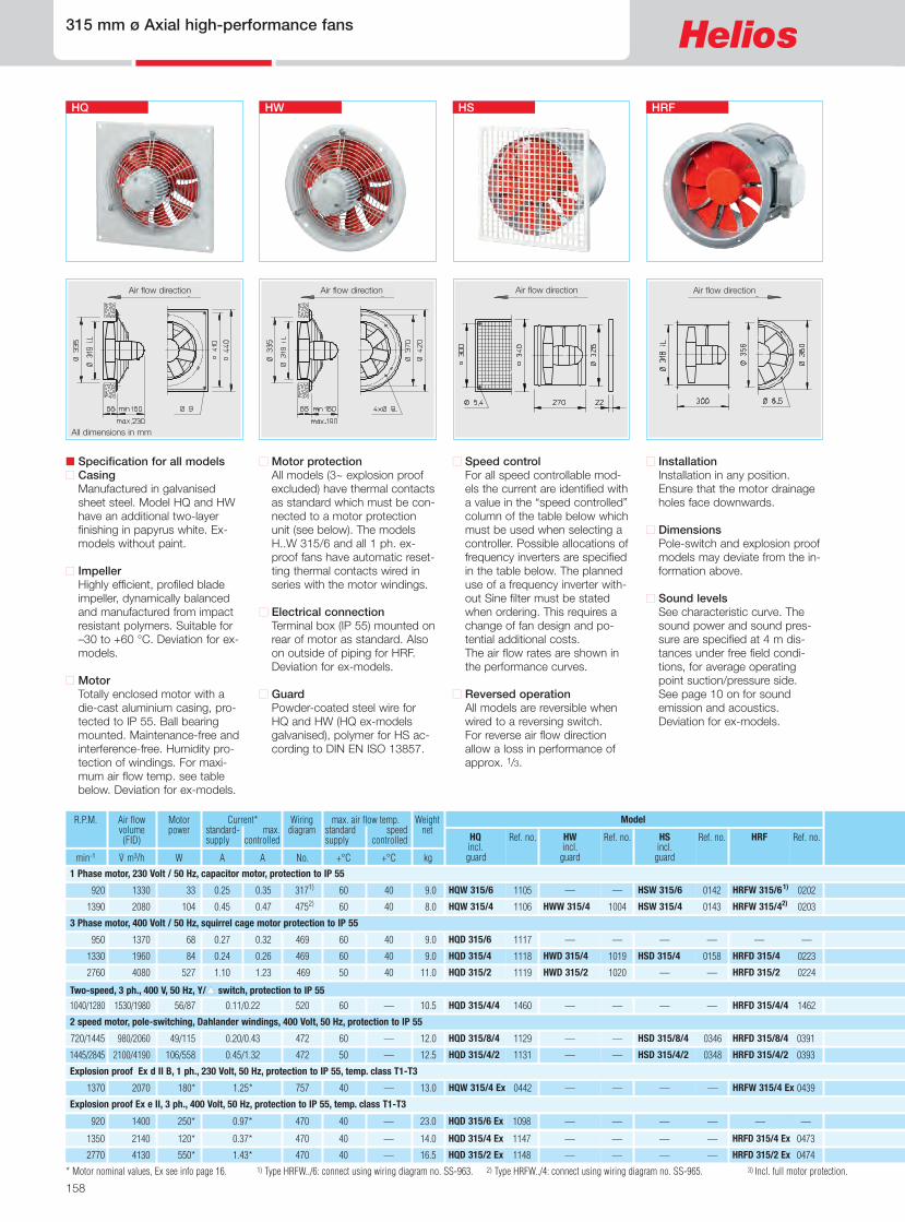
� Specification for all models� CasingManufactured in galvanisedsheet steel. Model HQ and HWhave an additional two-layer fin-ishing in papyrus white.
� ImpellerHighly efficient, profiled bladeimpeller, dynamically balancedand manufactured from impactresistant polymers. Suitable for–30 to +60 °C.
� MotorTotally enclosed motor with adie-cast aluminium casing, pro-tected to IP 54. Ball bearingmounted. Maintenance-free andinterference-free. Humidity pro-tection of windings. For maxi-mum air flow temperature seetable below.
� Motor protectionAll models have automaticallyresetting thermal contacts wiredin series with the motor wind-ings.
� Electrical connectionTerminal box (IP 54) mounted onrear of motor as standard. Alsoon outside of piping for HRF.
� GuardPowder-coated steel wire for HQ(Ex-models galvanised) accord-ing to DIN EN ISO 13857.
� Speed controlAll models are speed control-lable by voltage reduction (trans-former controller or electroniccontroller) For according air flowvolume see performance curve.
� Reversed operationAll models are reversible whenwired to a DSEL reversingswitch. For reverse air flowdirection allow for 1/3 drop inperformance.
� InstallationInstallation in any position.Ensure that the motor drainageholes face downwards.
� Sound levelsSee characteristic curve. Thesound power and sound pres-sure are specified at 1 m dis-tances under free field condi-tions, for average operatingpoint suction/pressure side.See page 10 on for soundemission and acoustics.
HQ HW HS HRF
R.P.M. Motorpower
Air flowvolume(FID)
Current* standard- max. supply controlled
No.
max. air flow temp. standard speed supply controlled
Weightnet
Ref. no.HQincl.guard
Ref. no.HWincl.
guard
Ref. no. Ref. no.HSincl.
guard
HRF
Model
min-1 WV· m3/h A A +°C +°C kg
7537 7538HWW 200/4 7502 7540HSW 200/4 HRFW 200/41)4391)1360 25520 0.11 0.11 60 40 3.8
0960 HQW 200/2 —— 7503 0199HSW 200/2 HRFW 200/21)4391)2250 66930 0.26 0.31 40 40 2.7
HQW 200/4
1) Type HRFW: connect pursuant to wiring diagram no. SS-962.
All dimensions in mm
1 Phase motor, 230 Volt / 50 Hz, capacitor motor, protection to IP 54
154
200 mm ø Axial high-performance fans
� Information PageTechn. description 140Selection chart 141Information for planning 10 on
Made to order designsAlternative voltages, protection classes, air flow direction, air flow temperature, acid protection and cast aluminium impellers are available on request.
Note the technical information on page 15 on.
Air flow direction Air flow direction Air flow direction Air flow direction

Reversing switch
155
Axial high-performance fans 200 mm ø
Axia
l and
VAR
fans
Transformer controllerfor 5 speed
Ref. no.Model
3608TSW 0,3
3608TSW 0,3
Electronic controller,stepless
flush/surf.
Ref. no.Model
0236/0238ESU 1/ESA 1
0236/0238ESU 1/ESA 1
Electronic controllerwith reversing switch
Ref. no.Model Ref. no.Model
1306DSEL 2
1306DSEL 2
0240BSX
0240BSX
Bell mountASD 200No. 1388
Flang. flex.connectorSTS 200No. 1219
Counter-flangeFR 200No. 1202
FlexiblesleeveFM 200No. 1670
GuardSG 200No. 1216
2 mounting feet1 x MK 200(= 2 pcs.)No. 1446
4 vibration dampers forsuspension1 x SDZ 1 (= 4 pcs.) No. 14544 vibration dampers forcompression1 x SDD 1 (= 4 pcs.) No. 1452
SDZ 1
SDD 1
Frequency Hz Total 125 250 500 1k 2k 4k 8k LWA Air noise dB(A) 50 32 38 42 44 44 41 33 LPA,1m Air noise dB(A) 42 24 30 34 36 36 33 25
200/4
DpfaPa
V· m3/h
r = 1.20 kg/m3
Frequency Hz Total 125 250 500 1k 2k 4k 8k LWA Air noise dB(A) 63 33 50 59 59 54 53 45 LPA,1m Air noise dB(A) 55 25 42 51 51 46 45 37
200/2
DpfaPa
V· m3/h
r = 1.20 kg/m3
Accessories for HRF Description see page 230 on
230 V 170 V 130 V 100 V 80 V
1 phase.a
b
c
d
e
230 V 170 V 130 V 100 V 80 V
1 phase.a
b
c
d
e
a
b
c
de
a
b
c
d
e
� Other accessories Page
Extension tube for HSType VH 200 Ref. no. 1349Cylindrical duct, galvanised steel,length: 150 mm.
Attenuators 421 onShutters and grilles 487 onSpeed controllersand switches 525 on

156
250 mm ø Axial high-performance fans
1144 — — — 0470— HRFD 250/4 Ex470 1350 1070 0.37* 40 — 12 HQD 250/4 Ex 120*
1145 — — — 0471— HRFD 250/2 Ex470 2800 2070 0.75* 40 — 11 HQD 250/2 Ex 250*
1102 — — 0139 — HSW 250/6 — 317 930 660 0.20 0.22 60 40
60 40
6.5
1103 HQW 250/41) 1001 HWW 250/41) 0140 0200 HSW 250/41) HRFW 250/41)2) 4392) 1300 36 930 0.15 0.15 60 40 7.5
HQW 250/6
1104 1002 HWW 250/2 0141 0201 HSW 250/2 HRFW 250/23) 3173) 2710 187 2070 0.81 0.9 6.5 HQW 250/2
35
1114 — — — —— —469 980 700 0.27 0.33 60 40 6.5
1115 HQD 250/41) 1016 HWD 250/41) 0155 0220 HSD 250/41) HRFD 250/41)469 1390 55 950 0.15 0.15 60 40 6.5
HQD 250/6 61
60 40 1116 1017 HWD 250/2 — 0221— HRFD 250/2469 2550 169 2000 0.31 0.33 6.5 HQD 250/2
1128 — — — 0390— HRFD 250/4/2472 1430/2770 1030/2110 0.16/0.43 60 — 8.5 HQD 250/4/2 58/212
0438 — — — 0437— HRFW 250/4 Ex757 1400 1030 0.70* 40 — 12 HQW 250/4 Ex 60*
1094 — — — 1095— HRFW 250/2 Ex757 2690 1950 1.23* 40 — 13 HQW 250/2 Ex 180*
� Motor protectionAll models (3~ explosion proofexcluded) have thermal contactsas standard which must be con-nected to a motor protectionunit (see below). The modelsH..W 250/6, H..W 250/4 andall 1 ph. ex-proof fans haveautomatic resetting thermalcontacts wired in series withthe motor windings.
� Electrical connectionTerminal box (IP 54/55) mountedon rear of motor as standard.Also on outside of piping forHRF. Deviation for ex-models.
� GuardPowder-coated steel wire forHQ and HW (HQ ex-models gal-vanised) according to DIN ENISO 13857.
� Specification for all models� CasingManufactured in galvanisedsheet steel. Model HQ and HWhave an additional two-layer fin-ishing in papyrus white. Ex-models without paint.
� ImpellerHighly efficient, profiled bladeimpeller, dynamically balancedand manufactured from impactresistant polymers. Suitable for–30 to +60 °C. Deviation for ex-models.
� MotorTotally enclosed motor with adie-cast aluminium casing, pro-tected to IP 55 or IP 54. Ballbearing mounted. Maintenance-free and interference-free. Hu-midity protection of windings.For maximum air flow tempera-ture see table below. Deviationfor ex-models.
� InstallationInstallation in any position.Ensure that the motor drainageholes face downwards.
� DimensionsPole-switch and explosion proofmodels may deviate from the in-formation above.
� Sound levelsSee characteristic curve. Thesound power and sound pres-sure are specified at 4 m dis-tances under free field condi-tions, for average operatingpoint suction/pressure side. Seepage 10 on for sound emissionand acoustics. Deviation for ex-models.
R.P.M. Motorpower
Air flowvolume(FID)
Current* standard- max. supply controlled
Wiringdiagram
No.
max. air flow temp. standard speed supply controlled
Weightnet
Ref. no.HQincl.guard
Ref. no.HWincl.
guard
Ref. no. Ref. no.HSincl.
guard
HRF
Model
min-1 WV· m3/h A A +°C +°C kg
* Motor nominal values, Ex see info page 16. 1) Special design not possible. 2) Type HRFW: connect using wiring diagram no. SS-962. 3) Type HRFW../2: connect using wiring diagram no. SS-963.
� Speed controlFor all speed controllable mod-els the current are identified witha value in the “speed controlled”column of the table below whichmust be used when selecting acontroller. Possible allocations offrequency inverters are specifiedin the table below. The planneduse of a frequency inverter with-out Sine filter must be statedwhen ordering. This requires achange of fan design and po-tential additional costs.The air flow rates are shown inthe performance curves.
� Reversed operationAll models are reversible whenwired to a reversing switch.For reverse air flow directionallow a loss in performance ofapprox. 1/3.
All dimensions in mm
1 Phase motor, 230 Volt / 50 Hz, capacitor motor, protection to IP 54/IP 55
3 Phase motor, 400 Volt / 50 Hz, squirrel cage motor protection to IP 55
2 speed motor, pole-switching, Dahlander windings, 400 Volt, 50 Hz, protection to IP 55
Explosion proof Ex d II B, 1 ph., 230 Volt, 50 Hz, protection to IP 55, temp. class T1-T3
Explosion proof Ex e II, 3 ph., 400 Volt, 50 Hz, protection to IP 55, temp. class T1-T3
� Information PageTechn. description 140Selection chart 141Information for planning 10 on
HQ HW HS HRF
Air flow direction Air flow direction Air flow direction Air flow direction

not permitted
not permitted
not permitted
not permitted
not permitted not permitted
not permitted not permitted
Frequency inverterwith integrated
Sine filter
— —
Ref. no.Model
— —
— —
FU-BS 2,54) 5459
FU-BS 2,54) 5459
FU-BS 2,54) 5459
— —
— —
— —
— —
— —
157
Axial high-performance fans 250 mm ø
Axia
l and
VAR
fans
Accessories for HRF Description see page 230 on
4) Incl. full motor protection. 5) Incl. pole switch. 6) See switch product page for flush mounted version
Transformer controller5-speed
Pole switch
Ref. no.Model
3608 TSW 0,3
3608 TSW 0,3
Electronic controller,stepless
flush/surf.
Ref. no.Model
0236/0238ESU 1/ESA 1
0236/0238ESU 1/ESA 1
Full motor protectionfor connection of inte-grated thermal contacts
Reversing switch
Ref. no.Model Ref. no.Model
——
——
1271 WS
1947 MWS 1,5 0237/0239ESU 3/ESA 3 1579MW 1271 WS
1306 DSEL 2
1314 RDS 14)
1314 RDS 14)——
——
5849 MD
5849 MD
1271 WS
1314 RDS 14) —— 5849 MD 1271 WS
1271 WS
5081 PDA 126) —— 1293 M 35) 1282 PWDA
—— ——
—— ——
—— ——
—— ——
Bell mount withguardASD-SGD 250No. 1414
Flang. flex.connectorSTS 250 b)
No. 1220
Automatic back-draught shutterRVS 250 a)
No. 2592
CircularattenuatorRSD 250/..
ExtensionductVR 250No. 1402
CounterflangeFR 250No. 1203
FlexiblesleeveFM 250 b)
No. 1672
Guard
SG 250Nr. 1236
2 mounting feet1 x MK 250(= 2 pcs.)No. 1447
4 vibration dampers forsuspension1 x SDZ 1 (= 4 pcs.) No.14544 vibration dampers forcompression1 x SDD 1 (= 4 pcs.) No.1452
SDZ 1
SDD 1
a) For motorised shutters see accessory page b) Models for ex-proof fans see below
Frequency Hz Total 125 250 500 1k 2k 4k 8k LWA Air noise dB(A) 53 40 47 47 46 43 37 30 LPA,4m Air noise dB(A) 33 20 27 27 26 23 17 10
250/6
DpfaPa
��
�
V· m3/h
r = 1.20 kg/m3
Frequency Hz Total 125 250 500 1k 2k 4k 8k LWA Air noise dB(A) 64 50 54 61 57 55 50 41 LPA,4m Air noise dB(A) 44 30 34 41 37 35 30 21
250/4
DpfaPa
�
�
�
�
V· m3/h
r = 1.20 kg/m3
Frequency Hz Total 125 250 500 1k 2k 4k 8k LWA Air noise dB(A) 75 38 53 66 68 70 69 62 LPA,4m Air noise dB(A) 55 18 33 46 48 49 48 42
250/2
DpfaPa
�
�
�
V· m3/h
r = 1.20 kg/m3
Frequency Hz Total 125 250 500 1k 2k 4k 8k LWA Air noise dB(A) 55 37 43 47 49 49 46 38 LPA,4m Air noise dB(A) 35 17 23 27 29 29 26 18
250/4
DpfaPa
V· m3/h
r = 1.20 kg/m3
� 400 V� 280 V� 200 V� 140 V� 80 V
3 phase
� 400 V� 280 V� 200 V� 140 V� 80 V
3 phase
� 400 V� 280 V� 200 V� 140 V� 80 V
3 phase
�
�
230 V 170 V 130 V 100 V 80 V
1 phasea
b
c
d
e
230 V 170 V 130 V 100 V 80 V
1 phase.a
b
c
d
e
230 V 170 V 130 V 100 V 80 V
1 phasea
b
c
d
e
a
c
d
b
e
ab
c
de
�a
b
c
d
e
Pole switch
� Other accessories Pageb) Accessories for explosionproof fans
Flanged flexible connectorType STS 250 Ex Ref. no. 2501Flexible sleeveType FM 250 Ex Ref. no. 1688
Extension tube for HSType VH 250 Ref. no. 1343Cylindrical duct, galvanised steel,length: 150 mm.
Attenuators 421 onShutters and grilles 487 onSpeed controllersand switches 525 on
�
FlatflangeFF 250No.4941
�
Single phase
Three phase
158
315 mm ø Axial high-performance fans
� Specification for all models� CasingManufactured in galvanisedsheet steel. Model HQ and HWhave an additional two-layerfinishing in papyrus white. Ex-models without paint.
� ImpellerHighly efficient, profiled bladeimpeller, dynamically balancedand manufactured from impactresistant polymers. Suitable for–30 to +60 °C. Deviation for ex-models.
� MotorTotally enclosed motor with adie-cast aluminium casing, pro-tected to IP 55. Ball bearingmounted. Maintenance-free andinterference-free. Humidity pro-tection of windings. For maxi-mum air flow temp. see tablebelow. Deviation for ex-models.
� Motor protectionAll models (3~ explosion proofexcluded) have thermal contactsas standard which must be con-nected to a motor protectionunit (see below). The modelsH..W 315/6 and all 1 ph. ex-proof fans have automatic reset-ting thermal contacts wired inseries with the motor windings.
� Electrical connectionTerminal box (IP 55) mounted onrear of motor as standard. Alsoon outside of piping for HRF.Deviation for ex-models.
� GuardPowder-coated steel wire forHQ and HW (HQ ex-modelsgalvanised), polymer for HS ac-cording to DIN EN ISO 13857.
� Speed controlFor all speed controllable mod-els the current are identified witha value in the “speed controlled”column of the table below whichmust be used when selecting acontroller. Possible allocations offrequency inverters are specifiedin the table below. The planneduse of a frequency inverter with-out Sine filter must be statedwhen ordering. This requires achange of fan design and po-tential additional costs.The air flow rates are shown inthe performance curves.
� Reversed operationAll models are reversible whenwired to a reversing switch.For reverse air flow directionallow a loss in performance ofapprox. 1/3.
� InstallationInstallation in any position.Ensure that the motor drainageholes face downwards.
� DimensionsPole-switch and explosion proofmodels may deviate from the in-formation above.
� Sound levelsSee characteristic curve. Thesound power and sound pres-sure are specified at 4 m dis-tances under free field condi-tions, for average operatingpoint suction/pressure side.See page 10 on for soundemission and acoustics.Deviation for ex-models.
R.P.M. Motorpower
Air flowvolume(FID)
Current* standard- max. supply controlled
Wiringdiagram
No.
max. air flow temp. standard speed supply controlled
Weightnet
Ref. no.HQincl.guard
Ref. no.HWincl.
guard
Ref. no. Ref. no.HSincl.
guard
HRF
Model
min-1 WV· m3/h A A +°C +°C kg
1460 — — — 1462— HRFD 315/4/4520 1040/1280 1530/1980 0.11/0.22 60 — 10.5 HQD 315/4/4 56/87
1105 — — 0142 0202 HSW 315/6 HRFW 315/61) 3171) 920 1330 0.25 0.35 60 40 9.0
1106 HQW 315/4 1004 HWW 315/4 0143 0203 HSW 315/4 HRFW 315/42) 4752) 1390 104 2080 0.45 0.47 60 40 8.0
HQW 315/6 33
1117 — — — —— —469 950 1370 0.27 0.32 60 40
50 40
9.0
1118 HQD 315/4 1019 HWD 315/4 0158 0223 HSD 315/4 HRFD 315/4469 1330 84 1960 0.24 0.26 60 40 9.0
HQD 315/6
1119 1020 HWD 315/2 — 0224— HRFD 315/2469 2760 527 4080 1.10 1.23 11.0 HQD 315/2
68
1129 — — 0346 0391 HSD 315/8/4 HRFD 315/8/4472 720/1445 980/2060 0.20/0.43 60 — 12.0 HQD 315/8/4 49/115
1131 — — 0348 0393 HSD 315/4/2 HRFD 315/4/2472 1445/2845 2100/4190 0.45/1.32 50 — 12.5 HQD 315/4/2 106/558
0442 — — — 0439— HRFW 315/4 Ex757 1370 2070 1.25* 40 — 13.0 HQW 315/4 Ex 180*
1147 — — — 0473— HRFD 315/4 Ex470 1350 2140 0.37* 40 — 14.0 HQD 315/4 Ex 120*
1148 — — — 0474— HRFD 315/2 Ex470 2770 4130 1.43* 40 — 16.5 HQD 315/2 Ex 550*
All dimensions in mm
HQ HW HS HRF
1098 — — — —— —470 920 1400 0.97* 40 — 23.0 HQD 315/6 Ex 250*
* Motor nominal values, Ex see info page 16. 1) Type HRFW../6: connect using wiring diagram no. SS-963. 2) Type HRFW../4: connect using wiring diagram no. SS-965. 3) Incl. full motor protection.
1 Phase motor, 230 Volt / 50 Hz, capacitor motor, protection to IP 55
3 Phase motor, 400 Volt / 50 Hz, squirrel cage motor protection to IP 55
Two-speed, 3 ph., 400 V, 50 Hz, Y/� switch, protection to IP 55
2 speed motor, pole-switching, Dahlander windings, 400 Volt, 50 Hz, protection to IP 55
Explosion proof Ex d II B, 1 ph., 230 Volt, 50 Hz, protection to IP 55, temp. class T1-T3
Explosion proof Ex e II, 3 ph., 400 Volt, 50 Hz, protection to IP 55, temp. class T1-T3
Air flow direction Air flow direction Air flow direction Air flow direction

not permitted not permitted
not permitted not permitted
not permitted not permitted
— —
FU-BS 2,53) 5459
— —
— —
Frequency inverterwith integrated
Sine filter
— —
Ref. no.Model
— —
FU-BS 2,53) 5459
FU-BS 2,53) 5459
FU-BS 2,53) 5459
— —
— —
159
Axial high-performance fans 315 mm ø
Axia
l and
VAR
fans
Accessories for HRF Description see page 230 on
4) Incl. pole switch. 5) See switch product page for flush mounted version.
Transformer controller5-speed
Pole switch
Ref. no.Model
Electronic controller,stepless
flush/surf.
Ref. no.Model
Full motor protectionfor connection of inte-grated thermal contacts
Reversing switch
Ref. no.Model Ref. no.Model
1351 DS2 —— 1571/5849M 44)/MD 1271 WS
3608 TSW 0,3
1947 MWS 1,53)0236/0238ESU 1/ESA 1
0236/0238ESU 1/ESA 1
——
1579 MW
1271 WS
1271 WS
1314 RDS 13)
1315 RDS 23)——
0501ESD 5
5849 MD
5849 MD
1271 WS
1271 WS
5081 PDA 125) —— 1293 M 34) 1282 PWDA
5081 PDA 125) —— 1293 M 34) 1282 PWDA
1314 RDS 13) —— 5849 MD 1271 WS
—— ——
—— ——
—— ——
Bell mount withguardASD-SGD 315No. 1416
Flang. flex.connectorSTS 315 b)
No. 1221
Automatic back-draught shutterRVS 315 a)
No. 2594
CircularattenuatorRSD 315/..
ExtensionductVR 315No. 1404
CounterflangeFR 315No. 1204
FlexiblesleeveFM 315 b)
No. 1674
GuardSG 315No. 1237
2 mounting feet1 x MK 315(= 2 pcs.)No. 1448
Mounting ring for vertical mountingMRV 315 No. 1755
a) For motorised shutters see accessory page b) Models for ex-proof fans see below
Frequency Hz Total 125 250 500 1k 2k 4k 8k LWA Air noise dB(A) 49 35 45 43 43 38 32 28 LPA,4m Air noise dB(A) 29 15 25 23 23 18 12 8
315/8
DpfaPa
V· m3/h
r = 1.20 kg/m3
Frequency Hz Total 125 250 500 1k 2k 4k 8k LWA Air noise dB(A) 70 56 60 67 63 61 56 47 LPA,4m Air noise dB(A) 50 36 40 47 43 41 36 27
315/4
DpfaPa
�
�
�
�
V· m3/h
r = 1.20 kg/m3
Frequency Hz Total 125 250 500 1k 2k 4k 8k LWA Air noise dB(A) 89 61 71 87 81 81 75 65 LPA,4m Air noise dB(A) 69 41 51 67 61 61 55 45
315/2
DpfaPa
�
�
�
�
�
V· m3/h
r = 1.20 kg/m3
Frequency Hz Total 125 250 500 1k 2k 4k 8k LWA Air noise dB(A) 59 46 53 53 53 49 43 36 LPA,4m Air noise dB(A) 39 26 33 33 33 29 23 16
315/6
DpfaPa
�
�
�
�
V· m3/h
r = 1.20 kg/m3
� 400 V� 280 V� 200 V� 140 V� 80 V
3 phase� 400 V� D 400 V� 280 V� Y 400 V� Y 200 V� 140 V 80 V
3 phase
�
� 400 V� 280 V� 200 V� 140 V� 80 V
3 phase
230 V 170 V 130 V 100 V 80 V
1 phasea
b
c
d
e
a
b
c
ed
230 V 170 V 130 V 100 V 80 V
1 phasea
b
c
d
e
c
d
e
ba
� Other accessories Pageb) Accessories for explosionproof fans
Flanged flexible connectorType STS 315 Ex Ref. no. 2503Flexible sleeveType FM 315 Ex Ref. no. 1690
Extension tube for HSType VH 315 Ref. no. 1344Cylindrical duct, galvanised steel,length: 150 mm.
Attenuators 421 onShutters and grilles 487 onSpeed controllersand switches 525 on
FlatflangeFF 315No.4943
�
�
not permitted not permitted — — —— ——
Speed switch
Pole switch

Ref. no.HRF
1464 HRFD 355/4/4
0204 HRFW 355/61)
0205 HRFW 355/41)
——
0226 HRFD 355/4
0227 HRFD 355/2
0394 HRFD 355/8/4
0396 HRFD 355/4/2
0443 HRFW 355/4 Ex
0476 HRFD 355/4 Ex
0136 HRFD 355/2 Ex
160
355 mm ø Axial high-performance fans
� Specification for all models� CasingManufactured in galvanisedsheet steel. Model HQ and HWhave an additional two-layer fin-ishing in papyrus white. Ex-models without paint.
� ImpellerHighly efficient, profiled bladeimpeller, dynamically balancedand manufactured from impactresistant polymers. Suitable for–30 to +60 °C. Deviation for ex-models.
� MotorTotally enclosed motor with adie-cast aluminium casing, pro-tected to IP 55. Ball bearingmounted. Maintenance-free andinterference-free. Humidity pro-tection of windings. For maxi-mum air flow temp. see tablebelow. Deviation for ex-models.
� Motor protectionAll models (3~ explosion proofexcluded) have thermal contactsas standard which must be con-nected to a motor protectionunit (see below). 1 ph. ex-prooffans have automatic resettingthermal contacts wired in serieswith the motor windings.
� Electrical connectionTerminal box (IP 55) mounted onrear of motor as standard. Alsoon outside of piping for HRF.Deviation for ex-models.
� GuardPowder-coated steel wire forHQ and HW (HQ ex-models gal-vanised) according to DIN ENISO 13857.
� Speed controlFor all speed controllable mod-els the current are identified witha value in the “speed controlled”column of the table below whichmust be used when selecting acontroller. Possible allocations offrequency inverters are specifiedin the table below. The planneduse of a frequency inverter with-out Sine filter must be statedwhen ordering. This requires achange of fan design and po-tential additional costs.The air flow rates are shown inthe performance curves.
� Reversed operationAll models are reversible whenwired to a reversing switch.For reverse air flow directionallow a loss in performance ofapprox. 1/3.
� InstallationInstallation in any position.Ensure that the motor drainageholes face downwards.
� DimensionsPole-switch and explosion proofmodels may deviate from the in-formation above.
� Sound levelsSee characteristic curve. Thesound power and sound pres-sure are specified at 4 m dis-tances under free field condi-tions, for average operatingpoint suction/pressure side.See page 10 on for soundemission and acoustics.Deviation for ex-models.
All dimensions in mm
R.P.M. Motorpower
Air flowvolume(FID)
Current* standard- max. supply controlled
Wiringdiagram
No.
max. air flow temp. standard speed supply controlled
Weightnet
Ref. no.HQincl.guard
Ref. no.HWincl.
guard
Model
min-1 WV· m3/h A A +°C +°C kg
1463 — — 520 1120/1350 2460/2860 0.17/0.32 60 — 11.0 HQD 355/4/4 90/132
1107 — — 4751) 960 1940 0.47 0.47 60 40 12
1108 HQW 355/4 1006 HWW 355/4 4751) 1345 130 2850 0.60 0.65 60 40 11
HQW 355/6 75
1120 — — 469 960 1970 0.27 0.29 60 40
60 40
9.5
1121 HQD 355/4 1022 HWD 355/4 469 1375 130 2900 0.35 0.35 60 40 11.0
HQD 355/6
1122 1023 HWD 355/2 469 2670 825 5710 1.60 1.60 15.0 HQD 355/2
70
1132 — — 472 700/1395 1430/2920 0.14/0.35 60 — 11.0 HQD 355/8/4 45/145
1134 — — 472 1430/2840 3050/6150 0.63/2.30* 40 — 16.0 HQD 355/4/2 250/950*
0444 — — 757 1370 2940 1.25* 40 — 18.0 HQW 355/4 Ex 180*
1150 — — 470 1350 3060 0.37* 40 — 18.0 HQD 355/4 Ex 120*
1261 — — 470 2830 5910 2.60* 40 — 12.5 HQD 355/2 Ex 1100*
HQ HW HRF
——1101 — — 470 920 2010 0.97* 40 — 25.0 HQD 355/6 Ex 250*
* Motor nominal values, Ex see info page 16. 1) Type HRFW: connect using wiring diagram no. SS-965. 2) Incl. full motor protection. 3) Incl. pole switch.
1 Phase motor, 230 Volt / 50 Hz, capacitor motor, protection to IP 55
3 Phase motor, 400 Volt / 50 Hz, squirrel cage motor protection to IP 55
Two-speed, 3 ph., 400 V, 50 Hz, Y/� switch, protection to IP 55
2 speed motor, pole-switching, Dahlander windings, 400 Volt, 50 Hz, protection to IP 55
Explosion proof Ex d II B, 1 ph., 230 Volt, 50 Hz, protection to IP 55, temp. class T1-T3
Explosion proof Ex e II, 3 ph., 400 Volt, 50 Hz, protection to IP 55, temp. class T1-T3
Air flow directionAir flow directionAir flow direction

not permitted not permitted
not permitted not permitted
not permitted not permitted
1571/5849M 43)/MD
— —
— —
161
Axial high-performance fans 355 mm ø
Axia
l and
VAR
fans
1351 DS 2 —— 1271 WS
Accessories for HRF Description see page 230 on
4) See switch product page for flush mounted version.
Transformer controller5-speed
Pole switch
Ref. no.Model
Electronic controller,stepless
flush/surf.
Ref. no.Model
Full motor protectionfor connection of inte-grated thermal contacts
Reversing switch
Ref. no.Model Ref. no.Model
1947 MWS 1,52)
1947 MWS 1,52)0236/0238ESU 1/ESA 1
0236/0238ESU 1/ESA 1
1579 MW
1579 MW
1271 WS
1271 WS
1314 RDS 12)
1315 RDS 22)——
0501ESD 5
5849 MD
5849 MD
1271 WS
1271 WS
5081 PDA 124) —— 1293 M 33) 1282 PWDA
5081 PDA 124) —— 1289 MSA 1282 PWDA
1314 RDS 12) —— 5849 MD 1271 WS
—— ——
—— ——
—— ——
Bell mount withguardASD-SGD 355No. 1417
Flang. flex.connectorSTS 355 b)
No. 1222
Automatic back-draught shutterRVS 355 a)
No. 2595
CircularattenuatorRSD 355/..
ExtensionductVR 355No. 1405
CounterflangeFR 355No. 1205
FlexiblesleeveFM 355 b)
No. 1675
Guard
SG 355No. 1238
2 mounting feet1 x MK 355(= 2 pcs.)No. 1448
Mounting ring for vertical mountingMRV 355 No. 1759
a) For motorised shutters see accessory page b) Models for ex-proof fans see below
Frequency Hz Total 125 250 500 1k 2k 4k 8k LWA Air noise dB(A) 71 50 63 66 65 65 58 46 LPA,4m Air noise dB(A) 51 30 43 46 45 45 38 26
355/8
DpfaPa
V· m3/h
r = 1.20 kg/m3
Frequency Hz Total 125 250 500 1k 2k 4k 8k LWA Air noise dB(A) 71 49 64 65 64 64 57 45 LPA,4m Air noise dB(A) 51 29 44 45 44 44 37 25
355/4
DpfaPa
�
V· m3/h
r = 1.20 kg/m3
Frequency Hz Total 125 250 500 1k 2k 4k 8k LWA Air noise dB(A) 91 59 73 88 83 85 78 67 LPA,4m Air noise dB(A) 71 39 53 68 63 65 58 47
355/2
DpfaPa
�
�
�
�
�
V· m3/h
r = 1.20 kg/m3
Frequency Hz Total 125 250 500 1k 2k 4k 8k LWA Air noise dB(A) 62 50 57 56 56 53 47 40 LPA,4m Air noise dB(A) 42 30 37 36 36 33 27 20
355/6
DpfaPa
��
�
�
V· m3/h
r = 1.20 kg/m3
� 400 V� 280 V� 200 V� 140 V� 80 V
3 phase� 400 V� D 400 V� 280 V� Y 400 V� 200 V� 140 V 80 V
3 phase 230 V 170 V 130 V 100 V 80 V
1 phase.a
b
c
d
e
a
b
c
e
� 400 V� 280 V� 200 V� 140 V� 80 V
3 phase 230 V 170 V 130 V 100 V 80 V
1 phase
�
a
b
c
d
e
a
b
c
d
e
� Other accessories Pageb) Accessories for explosionproof fans
Flanged flexible connectorType STS 355 Ex Ref. no. 2504Flexible sleeveType FM 355 Ex Ref. no. 1691
Extension tube for HSType VH 355 Ref. no. 1345Cylindrical duct, galvanised steel,length: 150 mm.
Attenuators 421 onShutters and grilles 487 onSpeed controllersand switches 525 on
�
�
FlatflangeFF 355No.4944
�
FU-BS 2,52) 5459
— —
— —
Frequency inverterwith integrated
Sine filter
— —
Ref. no.Model
— —
— —
FU-BS 2,52) 5459
FU-BS 2,52) 5459
— —
d
�
�
not permitted not permitted — — —— ——
Speed switch
Pole switch

162
400 mm ø Axial high-performance fans
� Specification for all models� CasingManufactured in galvanisedsheet steel. Model HQ and HWhave an additional two-layer fin-ishing in papyrus white. Ex-models without paint.
� ImpellerHighly efficient, profiled bladeimpeller, dynamically balancedand manufactured from impactresistant polymers. Suitable for–30 to +60 °C. Deviation for ex-models.
� MotorTotally enclosed motor with adie-cast aluminium casing, pro-tected to IP 55. Ball bearingmounted. Maintenance-free andinterference-free. Humidity pro-tection of windings. For maxi-mum air flow temp. see tablebelow. Deviation for ex-models.
� Motor protectionAll models (explosion proof ex-cluded) have thermal contactsas standard which must be con-nected to a motor protectionunit (see below).
� Electrical connectionTerminal box (IP 55) mounted onrear of motor as standard. Alsoon outside of piping for HRF.Deviation for ex-models.
� GuardPowder-coated steel wire forHQ and HW (HQ ex-models gal-vanised) according to DIN ENISO 13857
� Speed controlFor all speed controllable mod-els the current are identified witha value in the “speed controlled”column of the table below whichmust be used when selecting acontroller. Possible allocations offrequency inverters are specifiedin the table below. The planned
� Sound levelsSee characteristic curve. Thesound power and sound pres-sure are specified at 4 m dis-tances under free field condi-tions, for average operatingpoint suction/pressure side.See page 10 on for soundemission and acoustics.Deviation for ex-models.
R.P.M. Motorpower
Air flowvolume(FID)
Current* standard- max. supply controlled
Wiringdiagram
No.
max. air flow temp. standard speed supply controlled
Weightnet
Ref. no.HQincl.guard
Ref. no.HWincl.
guard
Ref. no.HRF
Model
min-1 WV· m3/h A A +°C +°C kg
* Motor nominal values, Ex see info page 16. 1) Type HRFW: connect using wiring diagram no. SS-965. 2) Incl. full motor protection. 3) Incl. pole switch.
1465 — — 1466 HRFD 400/4/4 520 1325/1085 3170/3920 0.25/0.45 0.45 60 40 20.0 HQD 400/4/4 135/205
1110 — — 0206 HRFW 400/61) 4751) 930 2570 0.52 0.54 60 40 13.0
1111 HQW 400/4 1008 HWW 400/4 0207 HRFW 400/41) 4751) 1350 235 4010 1.00 1.10 60 40 14.0
HQW 400/6 77
1123 — — —— 469 950 2620 0.28 0.30 60 40 13.0
1124 HQD 400/4 1025 HWD 400/4 0229 HRFD 400/4 469 1330 200 3960 0.40 0.40 60 40 14.0
HQD 400/6 89
1137 — — 0399 HRFD 400/8/4 472 690/1390 2010/4100 0.25/0.60 — 60 — 13.0 HQD 400/8/4 70/250
1139 — — 0401 HRFD 400/4/2 472 1480/2940 4180/8540 1.00/5.20* — 40 — 24.0 HQD 400/4/2300/2310*
1153 — — 0479 HRFD 400/4 Ex 470 1370 4380 1.08* — 40 — 16.0 HQD 400/4 Ex 370*
1109 — — —— 470 920 2870 0.97* — 40 — 13.0 HQD 400/6 Ex 250*
1475 — — 1474 HRFD 400/2/2 520 2890/2600 7890/8400 3.00/5.60* 4.70 40 40 25.0 HQD 400/2/21300/2310*
2 speed motor, pole-switching, Dahlander windings, 400 Volt, 50 Hz, protection to IP 55
All dimensions in mm
3 Phase motor, 400 Volt / 50 Hz, squirrel cage motor protection to IP 55
Two-speed, 3 ph., 400 V, 50 Hz, Y/� switch, protection to IP 55
1 Phase motor, 230 Volt / 50 Hz, capacitor motor, protection to IP 55
Explosion proof Ex e II, 3 ph., 400 Volt, 50 Hz, protection to IP 55, temp. class T1-T3
� Information PageTechn. description 140Selection chart 141Information for planning 10 on
Made to order designsAlternative voltages, protection classes, air flow direction, air flow temperature, acid protection and cast aluminium impellers are available on request.
Note the technical information on page 15 on.
HQ HW HRF
use of a frequency inverter with-out Sine filter must be statedwhen ordering. This requires achange of fan design and po-tential additional costs. The air flow rates are shown inthe performance curves.
� Reversed operationAll models are reversible whenwired to a reversing switch.For reverse air flow directionallow a loss in performance ofapprox. 1/3.
� InstallationInstallation in any position. En-sure that the motor drainageholes face downwards.
� DimensionsPole-switch and explosion proofmodels may deviate from the in-formation above.
Air flow direction Air flow direction Air flow direction

not permitted
not permitted
not permitted
1571/5849M 44)/MD
1571/5849M 44)/MD
not permitted
—
163
Axial high-performance fans 400 mm ø
Axia
l and
VAR
fans
Accessories for HRF Description see page 230 on
4) see switch product page for flush mounted version.
Transformer controller5-speed
Pole switch
Ref. no.Model
Electronic controller,stepless
flush/surf.
Ref. no.Model
Full motor protectionfor connection of inte-grated thermal contacts
Reversing switch
Ref. no.Model Ref. no.Model
1314 RDS 12) —— 1271 WS
1351 DS 2 0501ESD 52) 1271 WS
1947 MWS 1,52)
1947 MWS 1,52)0236/0238ESU 1/ESA 1
0237/0239ESU 3/ESA 3
1579 MW
1579 MW
1271 WS
1271 WS
1314 RDS 12) —— 5849 MD 1271 WS
1314 RDS 12) —— 5849 MD 1271 WS
5081 PDA 124) —— 1293 M 33) 1282 PWDA
5081 PDA 124) —— 1293 M 33) 1282 PWDA
—— —
—— ——
Bell mount withguardASD-SGD 400No. 1418
Flang. flex.connectorSTS 400 b)
No. 1223
Automatic back-draught shutterRVS 400 a)
No. 2596
CircularattenuatorRSD 400/..
ExtensionductVR 400No. 1406
CounterflangeFR 400No. 1206
FlexiblesleeveFM 400 b)
No. 1676
Guard
SG 400No. 1239
2 mounting feet1 x MK 400(= 2 pcs.)No. 1449
Mounting ring for vertical mountingMRV 400 No. 1760
a) For motorised shutters see accessory page b) Models for ex-proof fans see below
Frequency Hz Total 125 250 500 1k 2k 4k 8k LWA Air noise dB(A) 55 42 46 48 50 48 42 35 LPA,4m Air noise dB(A) 35 22 26 28 30 28 22 15
400/8
DpfaPa
V· m3/h
r = 1.20 kg/m3
Frequency Hz Total 125 250 500 1k 2k 4k 8k LWA Air noise dB(A) 76 54 72 71 68 68 61 50 LPA,4m Air noise dB(A) 56 34 52 51 48 48 41 30
400/4
DpfaPa
�
�
V· m3/h
r = 1.20 kg/m3
Frequency Hz Total 125 250 500 1k 2k 4k 8k LWA Air noise dB(A) 91 58 72 85 86 86 79 69 LPA,4m Air noise dB(A) 71 38 52 65 66 66 59 49
400/2
DpfaPa
V· m3/h
r = 1.20 kg/m3
Frequency Hz Total 125 250 500 1k 2k 4k 8k LWA Air noise dB(A) 66 53 60 60 59 56 50 43 LPA,4m Air noise dB(A) 46 33 40 40 39 36 30 23
400/6
DpfaPa
�
�
�
�
V· m3/h
r = 1.20 kg/m3
� 400 V� D 400 V� 280 V� Y 400 V� 200 V� 140 V 80 V
3 phase
�
�
� 400 V� 280 V� 200 V� 140 V� 80 V
3 phase
a
b
c
d
e
� D 400 V� Y 400 V
3 phase
230 V 170 V 130 V 100 V 80 V
1 phase.a
b
c
d
e
b
d
a
b
c
de
a
c
e
� Other accessories Pageb) Accessories for explosionproof fans
Flanged flexible connectorType STS 400 Ex Ref. no. 2505Flexible sleeveType FM 400 Ex Ref. no. 1692
Extension tube for HSType VH 400 Ref. no. 1346Cylindrical duct, galvanised steel,length: 150 mm.
Attenuators 421 onShutters and grilles 487 onSpeed controllersand switches 525 on
�
�
FlatflangeFF 400No.4945
�
�
230 V 170 V 130 V 100 V 80 V
1 phase
�
FU-BS 2,52) 5459
— —
— —
Frequency inverterwith integrated
Sine filter
— —
Ref. no.Model
— —
FU-BS 52) 5460
FU-BS 2,52) 5459
— —
— —
FU-BS 2,52) 5459
Pole switch
Speed switch

0.51/0.82 — 520
5.40/3.0* 5,10
164
450 mm ø Axial high-performance fans
� Specification for all models� CasingManufactured in galvanisedsheet steel. Model HQ and HWhave an additional two-layer fin-ishing in papyrus white. Ex-models without paint.
� ImpellerHighly efficient, profiled bladeimpeller, dynamically balancedand manufactured from impactresistant polymers. Suitable for–30 to +60 °C. Deviation for ex-models.
� MotorTotally enclosed motor with adie-cast aluminium casing, pro-tected to IP 55. Ball bearingmounted. Maintenance-free andinterference-free. Humidity pro-tection of windings. For maxi-mum air flow temp. see tablebelow. Deviation for ex-models.
� Motor protectionAll models (explosion proof ex-cluded) have thermal contactsas standard which must be con-nected to a motor protectionunit (see below).
� Electrical connectionTerminal box (IP 55) mounted onrear of motor as standard. Alsoon outside of piping for HRF.Deviation for ex-models.
� GuardPowder-coated steel wire forHQ and HW (HQ ex-models gal-vanised) according to DIN ENISO 13857.
� Speed controlFor all speed controllable mod-els the current are identified witha value in the “speed controlled”column of the table below whichmust be used when selecting acontroller. Possible allocations offrequency inverters are specifiedin the table below. The planneduse of a frequency inverter with-out Sine filter must be statedwhen ordering. This requires achange of fan design and po-tential additional costs.The air flow rates are shown inthe performance curves.
� Reversed operationAll models are reversible whenwired to a reversing switch.For reverse air flow directionallow a loss in performance ofapprox. 1/3.
� InstallationInstallation in any position.Ensure that the motor drainageholes face downwards.
� DimensionsPole-switch and explosion proofmodels may deviate from the in-formation above.
� Sound levelsSee characteristic curve. Thesound power and sound pres-sure are specified at 4 m dis-tances under free field condi-tions, for average operatingpoint suction/pressure side.See page 10 on for soundemission and acoustics.Deviation for ex-models.
R.P.M. Motorpower
Air flowvolume(FID)
Current* standard- max. supply controlled
Wiringdiagram
No.
max. air flow temp. standard speed supply controlled
Weightnet
Ref. no.HQincl.guard
Ref. no.HWincl.
guard
Ref. no.HRF
Model
min-1 WV· m3/h A A +°C +°C kg
* Motor nominal values, Ex see info page 16. 1) Type HRFW: connect using wiring diagram no. SS-965. 2) Incl. full motor protection. 3) see switch product page for flush mounted version.
1473 — — ——470 920 4090 0.97* — 40 — 15.5 HQD 450/6 Ex 250*
0995 — — ——472 480/970 1930/3950 0.22/0.47 — 60 — 18.0 HQD 450/12/6 62/163
0996 — — 0403HRFD 450/8/4472 705/1410 2860/5810 0.36/0.92 — 50 — 20.0 HQD 450/8/4 91/404
1467 — — 1468HRFD 450/4/4 1130/1390 5090/5780 60 — 22.0 HQD 450/4/4 280/378
0991 — — 0208HRFW 450/61) 4751) 915 3890 0.63 0.63 60 40 19.0
0992 HQW 450/4 1010 HWW 450/4 0209HRFW 450/41) 4751) 1380 405 5770 1.76 2.02 60 40 18.0
HQW 450/6 136
0993 — — 0230HRFD 450/6469 960 3920 0.38 0.42 60 40 18.0
0994 HQD 450/4 1028 HWD 450/4 0231HRFD 450/4469 1390 384 5810 0.81 0.92 50 40 17.0
HQD 450/6 137
1154 — — 0481HRFD 450/4 Ex470 1370 6240 1.08* — 40 — 15.5 HQD 450/4 Ex 370*
All dimensions in mm
— — 04845202775/2200 10190/9335 40 40 32.01300/2310* — — HRFD 450/2/2
1 Phase motor, 230 Volt / 50 Hz, capacitor motor, protection to IP 55
3 Phase motor, 400 Volt / 50 Hz, squirrel cage motor protection to IP 55
Two-speed, 3 ph., 400 V, 50 Hz, Y/� switch, protection to IP 55
Explosion proof Ex e II, 3 ph., 400 Volt, 50 Hz, protection to IP 55, temp. class T1-T3
HQ HW HRF
2 speed motor, pole-switching, Dahlander windings, 400 Volt, 50 Hz, protection to IP 55
Air flow direction Air flow direction Air flow direction

not permitted
not permitted
not permitted
not permitted
1571/5849M 44)/MD
1571/5849M 44)/MD
— —
— —
5081 PDA 123)
5081 PDA 123)
Transformer controller5-speed
Pole switch
Ref. no.Model
1351 DS 25)
1578 RDS 72)
1947 MWS 1,52)
1948 MWS 32)
1315 RDS 22)1314 RDS 12)
0502ESD 11,52)
Electronic controller,stepless
flush/surf.
Ref. no.Model
——
0237/0239ESU 3/ESA 3
0237/0239ESU 3/ESA 3
0501ESD 52)
——
——
——
Pole switch
1271 WS
165
Axial high-performance fans 450 mm ø
Axia
l and
VAR
fans
Accessories for HRF Description see page 230 on
4) Incl. pole switch. 5) Speed switch.
Full motor protectionfor connection of inte-grated thermal contacts
Reversing switch
Ref. no.Model Ref. no.Model
1271 WS
1579 MW
1579 MW
1271 WS
1271 WS
5849 MD 1271 WS
1293 M 34) 1282 PWDA
5849 MD 1271 WS
1293 M 34) 1282 PWDA
——
——
Bell mount withguardASD-SGD 450No. 1419
Flang. flex.connectorSTS 450 b)
No. 1224
Automatic back-draught shutterRVS 450 a)
No. 2597
CircularattenuatorRSD 450/..
ExtensionductVR 450No. 1407
CounterflangeFR 450No. 1207
FlexiblesleeveFM 450 b)
No. 1677
Guard
SG 450No. 1240
2 mounting feet1 x MK 450(= 2 pcs)No. 1449
Mounting ring for vertical mountingMRV 450 No. 1761
a) For motorised shutters see accessory page b) Models for ex-proof fans see below
0 2500 5000 7500 10000 125000
1000
250
500
750
Frequency Hz Total 125 250 500 1k 2k 4k 8k LWA Air noise dB(A) 98 72 89 91 96 90 87 79 LPA,4m Air noise dB(A) 78 52 69 71 76 70 67 59
450/2
DpfaPa
V· m3/h
r = 1.20 kg/m3
� D 400 V� 280 V� Y 400 V� 200 V� 140 V� 80 V
3 phase
���
�
�
�
Frequency Hz Total 125 250 500 1k 2k 4k 8k LWA Air noise dB(A) 78 52 69 73 73 72 67 60 LPA,4m Air noise dB(A) 58 32 49 53 53 52 47 40
450/8
DpfaPa
V· m3/h
r = 1.20 kg/m3
Frequency Hz Total 125 250 500 1k 2k 4k 8k LWA Air noise dB(A) 78 52 69 72 73 72 67 60 LPA,4m Air noise dB(A) 58 32 49 52 53 52 47 40
450/4
�
V· m3/h
r = 1.20 kg/m3
a
de
c
Frequency Hz Total 125 250 500 1k 2k 4k 8k LWA Air noise dB(A) 68 52 58 62 63 61 56 47 LPA,4m Air noise dB(A) 48 32 38 42 43 41 36 27
450/6
�
�
�
�
V· m3/h
r = 1.20 kg/m3
c
d
b
e
a
�
�
DpfaPa
DpfaPa
� 400 V� D 400 V� 280 V� Y 400 V� 200 V� 140 V Y 80 V
3 phase
� 400 V� 280 V� 200 V� 140 V� 80 V
3 phase 230 V 170 V 130 V 100 V 80 V
1 phasea
b
c
d
e
� Other accessories Pageb) Accessories for explosionproof fans
Flanged flexible connectorType STS 450 Ex Ref. no. 2506Flexible sleeveType FM 450 Ex Ref. no. 1693
Attenuators 421 onShutters and grilles 487 onSpeed controllersand switches 525 on
FlatflangeFF 450No.4946
�
� 230 V 170 V 130 V 100 V 80 V
1 phasea
b
c
d
e
FU-BS 2,52) 5459
— —
— —
Frequency inverterwith integrated
Sine filter
— —
Ref. no.Model
— —
FU-BS 8,02) 5461
FU-BS 2,52) 5459
— —
— —
FU-BS 2,52) 5459
b�
�
Speed switch

0483
0.76/1.19 —
0.29/0.46 —
166
500 mm ø Axial high-performance fans
� Specification for all models� CasingManufactured in galvanisedsheet steel. Model HQ and HWhave an additional two-layerfinishing in papyrus white. Ex-models without paint.
� ImpellerHighly efficient, profiled bladeimpeller, dynamically balancedand manufactured from impactresistant polymers. Suitable for–30 to +60 °C. Deviation for ex-models.
� MotorTotally enclosed motor with adie-cast aluminium casing, pro-tected to IP 55. Ball bearingmounted. Maintenance-free andinterference-free. Humidity pro-tection of windings. For maxi-mum air flow temp. see tablebelow. Deviation for ex-models.
� Motor protectionAll models (explosion proof ex-cluded) have thermal contactsas standard which must be con-nected to a motor protectionunit (see below).
� Electrical connectionTerminal box (IP 55) mounted onrear of motor as standard. Alsoon outside of piping for HRF.Deviation for ex-models.
� GuardPowder-coated steel wire for HQand HW (HQ ex-models gal-vanised) according to DIN ENISO 13857.
� Speed controlFor all speed controllable mod-els the current are identified witha value in the “speed controlled”column of the table below whichmust be used when selecting acontroller. Possible allocations of
frequency inverters are specifiedin the table below. The planneduse of a frequency inverter with-out Sine filter must be statedwhen ordering. This requires achange of fan design and po-tential additional costs. The air flow rates are shown inthe performance curves.
� Reversed operationAll models are reversible whenwired to a reversing switch.For reverse air flow directionallow a loss in performance ofapprox. 1/3.
� InstallationInstallation in any position. En-sure that the motor drainageholes face downwards.
� DimensionsPole-switch and explosion proofmodels may deviate from the in-formation above.
� Sound levelsSee characteristic curve. Thesound power and sound pres-sure are specified at 4 m dis-tances under free field condi-tions, for average operatingpoint suction/pressure side.See page 10 on for soundemission and acoustics.Deviation for ex-models.
R.P.M. Motorpower
Air flowvolume(FID)
Current* standard- max. supply controlled
Wiringdiagram
No.
max. air flow temp. standard speed supply controlled
Weightnet
Ref. no.HQincl.guard
Ref. no.HWincl.
guard
Ref. no.HRF
Model
min-1 WV· m3/h A A +°C +°C kg
* Motor nominal values, Ex see info page 16. 1) Type HRFW: connect using wiring diagram no. SS-965. 2) Incl. full motor protection. 3) Incl. pole switch.
1469 — — 1470HRFD 500/4/4520 1030/1350 6720/8150 60 — 24.0 HQD 500/4/4 416/617
1112 — — 0210HRFW 500/61) 4751) 935 5500 1.05 1.25 60 40 19.0
1113 HQW 500/4 — — 0211HRFW 500/41) 4751) 1375 1100* 8320 5.90* 4.94 40 40 25.0
HQW 500/6 233
1126 — — 0232HRFD 500/6469 920 5480 0.48 0.55 60 40 19.0
1127 HQD 500/4 1030 HWD 500/4 0233HRFD 500/4469 1345 620 8200 1.22 1.32 40 40 19.5
HQD 500/6 218
— — ——472 465/940 2680/5490 0.23/0.56 — 60 — 18.0 HQD 500/12/6 71/248
1471 — — ——520 615/920 4330/5450 60 — 18.0 HQD 500/6/6 133/214
1142 — — 0407HRFD 500/8/4472 700/1385 3890/8280 0.52/1.48 — 40 — 22.0 HQD 500/8/4 137/688
1157 — — HRFD 500/4 Ex470 1390 8560 2.00* — 40 — 18.0 HQD 500/4 Ex 750*
1050 — — 0489HRFD 500/6 Ex470 920 5610 0.97* — 40 — 18.0 HQD 500/6 Ex 250*
— — — 0485HRFD 500/2/2520 2450/2830 13615/12050 3.14/4.73* — 40 — 30.0 —1960/2470*
All dimensions in mm
� Information PageTechn. description 140Selection chart 141Information for planning 10 on
Made to order designsAlternative voltages, protection classes, air flow direction, air flow temperature, acid protection and cast aluminium impellers are available on request.
HQ HW HRF
1140
Two-speed, 3 ph., 400 V, 50 Hz, Y/� switch, protection to IP 55
Explosion proof Ex e II, 3 ph., 400 Volt, 50 Hz, protection to IP 55, temp. class T1-T3
1 Phase motor, 230 Volt / 50 Hz, capacitor motor, protection to IP 55
3 Phase motor, 400 Volt / 50 Hz, squirrel cage motor protection to IP 55
2 speed motor, pole-switching, Dahlander windings, 400 Volt, 50 Hz, protection to IP 55
Air flow direction Air flow direction Air flow direction

not permitted
not permitted
not permitted
not permitted
1571/5849M 44)/MD
1571/5849M 44)/MD
1571/5849M 44)/MD
— —
FU-BS 2,52) 5459
Frequency inverterwith integrated
Sine filter
— —
Ref. no.Model
— —
FU-BS 2,52) 5459
FU-BS 2,52) 5459
— —
— —
FU-BS 2,52) 5459
FU-BS 5,02) 5460
— —
167
Axial high-performance fans 500 mm ø
Axia
l and
VAR
fans
Accessories for HRF Description see page 230 on
4) See switch product page for flush mounted version. 5) Speed switch.
Transformer controller5-speed
Pole switch
Ref. no.Model
Electronic controller,stepless
flush/surf.
Ref. no.Model
Full motor protectionfor connection of inte-grated thermal contacts
Reversing switch
Ref. no.Model Ref. no.Model
1351 DS 25) 0501ESD 52) 1271 WS
1578 RDS 72) 0502ESD 11,52) 1271 WS
1947 MWS 1,52)
1949 MWS 52)0237/0239ESU 3/ESA 3
1296/1299ESU 5/ESA 5
1579 MW
1579 MW
1271 WS
1271 WS
1315 RDS 22) 0501ESD 52) 5849 MD 1271 WS
5081 PDA 124) —— 1293 M 33) 1282 PWDA
5081 PDA 124) —— 1293 M 33) 1282 PWDA
1314 RDS 12) 0501ESD 52) 5849 MD 1271 WS
1351 DS 25) —— 1271 WS
—— ——
—— ——
Bell mount withguardASD-SGD 500No. 1420
ExtensionductVR 500No. 1408
CircularattenuatorRSD 500/..
Flang. flex.connectorSTS 500 b)
No. 1225
Automatic back-draught shutterRVS 500 a)
No. 2598
Counter-flangeFR 500No. 1208
FlexiblesleeveFM 500 b)
No. 1678
Guard
SG 500No. 1241
2 mounting feet1 x MK 500(= 2 pcs)No. 1450
Mounting ring for vertical mountingMRV 500 No. 1740
a) For motorised shutters see accessory page b) Models for ex-proof fans see below
Frequency Hz Total 125 250 500 1k 2k 4k 8k LWA Air noise dB(A) 71 55 62 65 65 64 59 51 LPA,4m Air noise dB(A) 51 35 42 45 45 44 39 31
500/6
DpfaPa
�
�
�
V· m3/h
r = 1.20 kg/m3
Frequency Hz Total 125 250 500 1k 2k 4k 8k LWA Air noise dB(A) 81 56 74 75 75 74 69 63 LPA,4m Air noise dB(A) 61 36 54 55 55 54 49 43
500/4
DpfaPa
�
V· m3/h
r = 1.20 kg/m3
Frequency Hz Total 125 250 500 1k 2k 4k 8k LWA Air noise dB(A) 82 55 73 76 77 75 70 63 LPA,4m Air noise dB(A) 62 35 53 56 57 55 50 43
500/8
DpfaPa
V· m3/h
r = 1.20 kg/m3
� b
cde
a
d
e
a
0 2500 5000 7500 10000 12500 150000
250
500
750
Frequency Hz Total 125 250 500 1k 2k 4k 8k LWA Air noise dB(A) 101 75 92 94 99 93 90 82 LPA,4m Air noise dB(A) 81 55 72 74 79 73 70 62
500/2
DpfaPa
��
�
V· m3/h
r = 1.20 kg/m3
�
�
� D 400 V� 280 V� Y 400 V� 200 V� 140 V� 80 V
3 phase� 400 V� 280 V� 200 V� 140 V� 80 V
� D 400 V� Y 400 V� 280 V� Y 400 V� 200 V� 140 V Y 80 V
3 phase 230 V 170 V 130 V 100 V 80 V
1 phasea
b
c
d
e
� Other accessories Pageb) Accessories for explosionproof fans
Flanged flexible connectorType STS 500 Ex Ref. no. 2507Flexible sleeveType FM 500 Ex Ref. no. 1694
Extension tube for HSType VH 500 Ref. no. 1348Cylindrical duct, galvanised steel,length: 150 mm.
Attenuators 421 onShutters and grilles 487 onSpeed controllersand switches 525 on
�
�
c
FlatflangeFF 500No.4947
�
�
�
3 phase 230 V 170 V 130 V 100 V 80 V
1 phasea
b
c
d
e
b
�
Speed switch
Pole switch
�

168
560 mm ø Axial high-performance fans
� Specification for all models� CasingManufactured in galvanisedsheet steel. Model HQ have anadditional two-layer finishing inpapyrus white. Ex-models with-out paint.
� ImpellerHighly efficient, profiled bladeimpeller, dynamically balancedand manufactured from impactresistant polymers. Suitable for–30 to +60 °C. Deviation for ex-models.
� MotorTotally enclosed motor with adie-cast aluminium casing, pro-tected to IP 55. Ball bearingmounted. Maintenance-free andinterference-free. Humidity pro-tection of windings. For maxi-mum air flow temperature seetable below. Deviation for ex-models.
� Motor protectionAll models (except explosionproof) have thermal contacts asstandard which must be con-nected to a motor protectionunit (see below) for effective mo-tor protection.
� Electrical connectionTerminal box (IP 55) mounted onrear of motor as standard. Alsoon outside of piping for HRF.Deviation for ex-models.
� GuardPowder-coated steel wire for HQ(Ex-models galvanised) accord-ing to DIN EN ISO 13857.
� Speed controlFor all speed controllable mod-els the current are identified witha value in the “speed controlled”column of the table below whichmust be used when selecting acontroller. Possible allocations offrequency inverters are specifiedin the table below. The planneduse of a frequency inverter with-out Sine filter must be statedwhen ordering. This requires achange of fan design and po-tential additional costs.The air flow rates are shown inthe performance curves.
� Reversed operationAll models are reversible whenwired to a reversing switch.For reverse air flow directionallow a loss in performance ofapprox. 1/3.
� InstallationInstallation in any position.Ensure that the motor drainageholes face downwards.
� DimensionsPole-switch and explosion proofmodels may deviate from the in-formation above.
� Sound levelsSee characteristic curve. Thesound power and sound pres-sure are specified at 4 m dis-tances under free field condi-tions, for average operatingpoint suction/pressure side.See page 10 on for soundemission and acoustics.Deviation for ex-models.
HRF
R.P.M. Motorpower(nominal)*
Air flowvolume(FID)
Current* standard- max. supply controlled
Wiringdiagram
No.
max. air flow temp. standard speed supply controlled
Weightnet
Ref. no.HQincl.guard
Ref. no.HRF
Transformer controllerfor 5 speedpole switch
Model
min-1 kWV· m3/h A A +°C +°C kg
0385 0380HRFW 560/61) 4751) 935 8130 1.40 2.00 60 40 24.0 HQW 560/6 0.27
0386 0381HRFD 560/6469 965 8180 0.79 1.00 60 40 26.0
0387 HQD 560/4 0382HRFD 560/4469 1365 0.88 12250 1.71 1.80 40 40 29.0
HQD 560/6 0.28
0389 0384HRFD 560/12/6472 470/955 4000/8130 0.55/0.74 — 60 — 24.0 HQD 560/12/60.089/0.298
0388 0383HRFD 560/8/4472 720/1365 6400/12130 0.80/1.77 — 40 — 26.0 HQD 560/8/4 0.20/0.92
0379 0377HRFD 560/4 Ex470 1390 12890 2.00* — 40 — 24.0 HQD 560/4 Ex 0.75*
0378 0376HRFD 560/6 Ex470 920 8090 0.97* — 40 — 23.0 HQD 560/6 Ex 0.25*
* Ex-models: for nominal value of motor see information on page 16 1) Type HRFW: connect using wiring diagram no. SS-965 2) Incl. full motor protection 3) see switch product page for flush mounted version
Electronic controller,steplessflush/surf.
Ref. no.Model
0237/0239ESU 3/ESA 3
0501ESD 52)
——
0501ESD 52)
——
not permitted
not permitted
Ref. no.Model
MWS 32)
RDS 22)
PDA 123)
RDS 22)
PDA 123)
not permitted
not permitted
1948
5054 5055HRFW 560/4965 1370 12180 4.15 5.00 60 40 31.0 HQW 560/4 0.89 1296/1299ESU 5/ESA 5 MWS 7,52) 1950
1315
5081
1315
5081
HQ
All dimensions in mm
Explosion proof Ex e II, 3 ph., 400 Volt, 50 Hz, protection to IP 55, temp. class T1-T3
2 speed motor, pole-switching, Dahlander windings, 400 Volt, 50 Hz, protection to IP 55 Pole switch
1 Phase motor, 230 Volt / 50 Hz, capacitor motor, protection to IP 55
3 Phase motor, 400 Volt / 50 Hz, squirrel cage motor protection to IP 55
Air flow direction Air flow direction
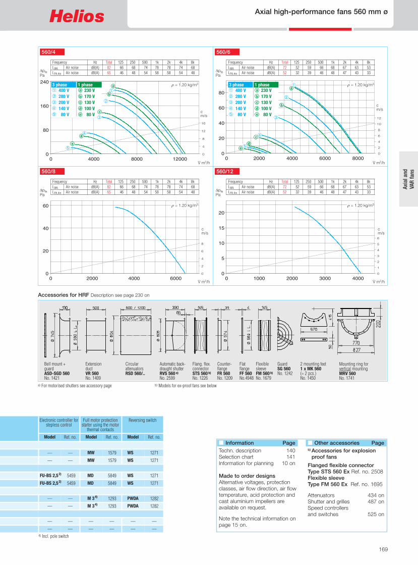
Ref. no.Model
Electronic controller forstepless control
——
5459 FU-BS 2,52)
——
5459 FU-BS 2,52)
——
——
——
——
169
Axial high-performance fans 560 mm ø
Axia
l and
VAR
fans
4) Incl. pole switch
Full motor protectionstarter using the motorthermal contacts
Reversing switch
Ref. no.Model Ref. no.Model
1579 MW 1271 WS
5849 MD 1271 WS
1293 M 34) 1282 PWDA
5849 MD 1271 WS
1293 M 34) 1282 PWDA
1579 MW 1271 WS
— — ——
— — ——
Bell mount +guardASD-SGD 560No. 1421
ExtensionductVR 560No. 1409
CircularattenuatorsRSD 560/..
Automatic back-draught shutterRVS 560 a)
No. 2599
Flang. flex.connectorSTS 560 b)
No. 1226
Counter-flangeFR 560No. 1209
FlexiblesleeveFM 560 b)
No. 1679
GuardSG 560No. 1242
2 mounting feet1 x MK 560(= 2 pcs.)No. 1450
Mounting ring for vertical mountingMRV 560 No. 1741
a) For motorised shutters see accessory page b) Models for ex-proof fans see below c) Typenzuordnung siehe Tabelle, letzte Spalte
Frequency Hz Total 125 250 500 1k 2k 4k 8k LWA Air noise dB(A) 72 52 59 66 68 67 63 53 LPA,4m Air noise dB(A) 52 32 39 46 48 47 43 33
560/12
DpfaPa
V· m3/h
r = 1.20 kg/m3
cm/s
Frequency Hz Total 125 250 500 1k 2k 4k 8k LWA Air noise dB(A) 72 52 59 66 68 67 63 53 LPA,4m Air noise dB(A) 52 32 39 46 48 47 43 33
560/6
DpfaPa
�
�
�
�
V· m3/h
r = 1.20 kg/m3
cm/s
Frequency Hz Total 125 250 500 1k 2k 4k 8k LWA Air noise dB(A) 82 66 68 74 78 78 74 68 LPA,4m Air noise dB(A) 65 46 48 54 58 58 54 48
560/4
DpfaPa
�
�
�
�
V· m3/h
r = 1.20 kg/m3
cm/s
Frequency Hz Total 125 250 500 1k 2k 4k 8k LWA Air noise dB(A) 82 66 68 74 78 78 74 68 LPA,4m Air noise dB(A) 65 46 48 54 58 58 54 48
560/8
DpfaPa
V· m3/h
r = 1.20 kg/m3
cm/s
� 400 V� 280 V� 200 V� 140 V� 80 V
3 phase 230 V 170 V 130 V 100 V 80 V
1 phasea
b
c
d
e
a
b
c
e
d
a
b
c
ed
� �
� 400 V� 280 V� 200 V� 140 V� 80 V
3 phase 230 V 170 V 130 V 100 V 80 V
1 phasea
b
c
d
e
FlatflangeFF 560No.4948
Accessories for HRF Description see page 230 on
� Information PageTechn. description 140Selection chart 141Information for planning 10 on
Made to order designsAlternative voltages, protection classes, air flow direction, air flow temperature, acid protection and cast aluminium impellers are available on request.
Note the technical information on page 15 on.
� Other accessories Pageb) Accessories for explosionproof fans
Flanged flexible connectorType STS 560 Ex Ref. no. 2508Flexible sleeveType FM 560 Ex Ref. no. 1695
Attenuators 434 onShutter and grilles 487 onSpeed controllersand switches 525 on

170
630 mm ø Axial high-performance fans
5030 HQD 630/4/4 1033 HWD 630/4/4 0245HRFD 630/4/45201170/1390 0.90/1.5714310/17000 2.3/3.8 — 40 — 37.5 RDS 41) 1316
� Specification for all models� CasingManufactured in galvanisedsheet steel.
� ImpellerHighly efficient, profiled bladeimpeller, dynamically balancedand manufactured from impactresistant polymers. Suitable for–30 to +60 °C. Deviation for ex-models.
� MotorTotally enclosed motor with adie-cast aluminium casing, pro-tected to IP 55. Ball bearingmounted. Maintenance-free andinterference-free. Humidity pro-tection of windings. For maxi-mum air flow temperature seetable below. Deviation for ex-models.
� Motor protectionAll models (except ../8/4 and ex-plosion proof) have thermal con-tacts as standard which mustbe connected to a motor pro-tection unit (see below) for effec-tive motor protection. Motorswithout thermal contacts mustbe protected by a conventionalcircuit breaker.
� Electrical connectionTerminal box (IP 55) mounted onmotor as standard. Also on out-side of piping for HRF. Deviationfor ex-models.
� GuardPowder-coated steel wire for HQand HW (HQ.. Ex galvanised)according to DIN EN ISO13857.
� Speed controlFor all speed controllable mod-els the current are identified witha value in the “speed controlled”column of the table below whichmust be used when selecting acontroller. Possible allocations offrequency inverters are specifiedin the table below. The planneduse of a frequency inverter with-out Sine filter must be statedwhen ordering. This requires achange of fan design and po-tential additional costs.The air flow rates are shown inthe performance curves.
� Reversed operationAll models are reversible whenwired to a reversing switch.For reverse air flow directional-low a loss in performance ofapprox. 1/3.
HW HRF
R.P.M. Motorpower(nominal)*
Air flowvolume(FID)
Current* standard- max. supply controlled
Wiringdiagram
No.
max. air flow temp. standard speed supply controlled
Weightnet
Ref. no.HQincl.guard
Ref. no.HWincl.guard
Ref. no.
Transformer controllerfor 5 speedpole switchHRF
Model
min-1 kWV· m3/h A A +°C +°C kg
5037 — — — — 475 950 10530 2.16 3.20 60 40 28.0 HQW 630/6 0.44
5029 — — — —469 710 7810 0.66 0.70 40 40 27.0
5027 HQD 630/6 1032 HWD 630/6 0244HRFD 630/6469 960 0.44 10560 1.22 — 60 40 30.5
HQD 630/8 0.20
5031 — — 0410HRFD 630/12/6472 440/935 5290/10470 0.60/1.13 60 — 41.0 HQD 630/12/6 0.14/0.43
5032 — — 0411HRFD 630/8/4471 690/1400 7990/15990 1.33/3.70* 40 — 40.5 HQD 630/8/4 0.37/1.50*
5036 — — 0495HRFD 630/4 Ex470 1410 17730 3.10* 40 — 35.0 HQD 630/4 Ex 1.35*
5035 — — 0494HRFD 630/6 Ex470 910 10480 1.75* 40 — 30.0 HQD 630/6 Ex 0.55*
* Ex-models: for nominal value of motor see information on page 16 1) Incl. full motor protection 2) see switch product page for flush mounted version
Ref. no.Model
MWS 31)
RDS 21)
PDA 122)
RDS 21)
PDA 122)
not permitted
not permitted
1948
5056 — — 5057HRFW 630/4 964 1325 16210 8.40* 7.00 40 — 40.0 HQW 630/4 1.50* MWS 7,51) 1950
1315
5081
1315
5081
HQ
All dimensions in mm
2 speed motor, pole-switching, Dahlander windings, 400 Volt, 50 Hz, protection to IP 55
Explosion proof Ex e II, 3 ph., 400 Volt, 50 Hz, protection to IP 55, temp. class T1-T3
3 Phase motor, 400 Volt / 50 Hz, squirrel cage motor protection to IP 55
1 Phase motor, 230 Volt / 50 Hz, capacitor motor, protection to IP 55
Type HRFW 630/4 motor buildlength with 25 mm projection.
Two-speed, 3 ph., 400 V, 50 Hz, Y/� switch, protection to IP 55
� InstallationInstallation in any position.Ensure that the motor drainageholes face downwards.
� DimensionsPole-switch and explosion proofmodels may deviate from the in-formation above.
� Sound levelsSee characteristic curve. Thesound power and sound pres-sure are specified at 4 m dis-tances under free field condi-tions, for average operatingpoint suction/pressure side.See page 10 on for soundemission and acoustics.Deviation for ex-models.
Air flow direction Air flow direction Air flow direction

——
——
——
Ref. no.Model
Frequency inverterwith integratedSine filter
——
5459 FU-BS 2,51)
5460 FU-BS 5,01)
5459 FU-BS 2,51)
——
——
——
——
171
Axial high-performance fans 630 mm ø
Axia
l and
VAR
fans
Electronic controller,steplessflush/surf.
Ref. no.Model
1296/1299ESU 5/ESA 5
Full motor protectionfor connection of inte-grated thermal contacts
Reversing switch
Ref. no.Model Ref. no.Model
1579 MW 1271WS
—— 1579 MW 1271WS
0501ESD 51) 5849 MD 1271WS
0501ESD 51) 1571 M 43) 1271WS
—— 1293 M 33) 1282 PWDA
0501ESD 51) 5849 MD 1271WS
—— 1293 M 33) 1282 PWDA
not permitted — — ——
not permitted — — ——
Accessories for HRF Description see page 230 on
Bell mount +guardASD-SGD 630No. 1422
ExtensionductVR 630No. 1410
CircularattenuatorsRSD 630/..
Flang. flex.connectorSTS 630 b)
No. 1228
Automatic back-draught shutterRVS 630 a)
No. 2600
CounterflangeFR 630No. 1211
FlexiblesleeveFM 630 b)
No. 1680
GuardSG 630No. 1243
2 mounting feet1 x MK 630(= 2 pcs.)No. 1333
Mounting ring for vertical mountingMRV 630 No. 1742
a) For motorised shutters see accessory page b) Models for ex-proof fans see below c) Typenzuordnung siehe Tabelle, letzte Spalte
Frequency Hz Total 125 250 500 1k 2k 4k 8k LWA Air noise dB(A) 75 55 62 69 71 70 66 56 LPA,4m Air noise dB(A) 55 35 41 49 51 50 46 36
630/12
DpfaPa
V· m3/h
r = 1.20 kg/m3
cm/s
Frequency Hz Total 125 250 500 1k 2k 4k 8k LWA Air noise dB(A) 75 55 62 69 71 70 66 56 LPA,4m Air noise dB(A) 55 35 41 49 51 50 46 36
630/6
DpfaPa
V· m3/h
r = 1.20 kg/m3
cm/s
Frequency Hz Total 125 250 500 1k 2k 4k 8k LWA Air noise dB(A) 85 69 71 77 81 77 70 65 LPA,4m Air noise dB(A) 65 49 51 57 61 61 57 50
630/4
DpfaPa
V· m3/h
r = 1.20 kg/m3
cm/s
Frequency Hz Total 125 250 500 1k 2k 4k 8k LWA Air noise dB(A) 85 69 71 77 81 77 70 65 LPA,4m Air noise dB(A) 65 49 51 57 61 61 57 50
630/8
DpfaPa
V· m3/h
r = 1.20 kg/m3
cm/s
� 400 V� D 400 V� 280 V� Y 400 V� 200 V� 140 V 80 V
3 phase �
�
�
�
�
� 400 V� 280 V� 200 V� 140 V� 80 V
3 phase�
�
�
�
��
�
�
�
� 400 V� 280 V� 200 V� 140 V� 80 V
3 phase
230 V 170 V 130 V 100 V 80 V
1 phasea
b
c
d
e
230 V 170 V 130 V 100 V 80 V
1 phase.a
b
c
d
e
a
b
c
e
d
b
c
ed
a
3) Incl. pole switch
FlatflangeFF 630No. 4949
�
�
�
� Information PageTechn. description 140Selection chart 141Information for planning 10 on
Made to order designsAlternative voltages, protection classes, air flow direction, air flow temperature, acid protection and cast aluminium impellers are available on request.
Note the technical information on page 15 on.
� Other accessories Pageb) Accessories for explosionproof fans
Flanged flexible connectorType STS 630 Ex Ref. no. 2509Flexible sleeveType FM 630 Ex Ref. no. 1696
Attenuators 434 onShutter and grilles 487 onSpeed controllersand switches 525 on

RDS 44)
RDS 74)
RDS 74)
172
710 mm ø Axial high-performance fans
� Specification for all models� CasingWith motor support manufac-tured from galvanised sheetsteel.
� ImpellerHighly efficient, profiled bladeimpeller, dynamically balancedand manufactured from impactresistant polymers. Suitable for–30 to +60 °C. Deviation for ex-models.
� Pitch angleThe impeller blades are ad-justable for the optimal coverageof the operating point (exceptHQW 710/6 and explosionproof). The pitch angle is setat the factory (according to the
� Speed controlPartial through voltage reduc-tion, see the “transformer con-troller” column. Regulated per-formance curve upon request.Possible allocations of frequencyinverters for all types (exceptpole-switch and ex-proof). Theplanned use of a frequency in-verter without Sine filter must bestated when ordering. This re-quires a change of fan designand potential additional costs.
� Reversed operationAll models are reversible whenwired to a reversing switch.For reverse air flow directionallow a loss in performance ofapprox. 1/3.
� InstallationInstallation in any position.Ensure that the motor drainageholes face downwards.
� DimensionsPole-switch and explosion proofmodels may deviate from theadjacent information. Motorbuild lengths vary. Note dimen-sion B projection.
� Sound levelsThe sound power levels arespecified through the frequencyand as sum levels above thecharacteristic curves. Deviationfor ex-models.
HQ AVD DK HRF/AVD RK
5602HQD 710/6/63) 5254AVD DK 710/6/63) 6933HRFD 710/6/63)25 730/890 0.4/0.75*13550/16090 400/400 520 55.0 1316
5604HQD 710/4/43) 5256AVD DK 710/4/43)201120/1360 0.95/1.55* 16140/19670 400/400 520 60.0 1578
5606HQD 710/42) 5258AVD DK 710/42) HRFD 710/42)301445 3.00* 26420 400/690 776 88.0 — —
R.P.M. Motorpower(nomi-nal)*
Air flowvolume(FID)
Power con.nom. volt./(control)*
Voltage Wiringdiagram
max.pitchangle
°
max. airflowtemp.
Weightnet**)
Ref. no.HQincl.guard
Ref. no.AVD DKincl.guard
Ref. no.
Transformer controllerfor 5 speedpole switchHRFD,
AVD RK
Model
min-1 kWV· m3/h V A +°CNo. kg
Dim. Bmotorprojection
mm
5047 —— ——25 910 14200 230 965 40.0 HQW 710/61) 0.60 —
95
95
135
180
180
180
210
125
95
135
200
180
5599HQD 710/81) 5251AVD DK 710/81) 6930
6935
6937
6936
6942
6943
6948
6949
6950
6952
6951
HRFD 710/81)20 690 0.29 13330 400 469 57.0
5263
5264
5270
5272
5273
5276
5275
5611 AVD DK 710/8/4/.. HRFD 710/8/4/..23 685/1430 10810/22090 400/400 471 82.0 HQD 710/8/4/.. 0.5/2.0*
5620 AVD DK 710/6 Ex HRFD 710/6 Ex25 930 13480 400 470 67.0 HQD 710/6 Ex 0.55*
5618 AVD DK 710/8 Ex HRFD 710/8 Ex35 700 10450 400 470 68.0 HQD 710/8 Ex 0.55*
Ref. no.Model
MWS 54)
RDS 24)
PDA 125)
not permitted
not permitted
5623 AVD DK 710/4 Ex AVD RK 710/4 Ex25 1420 20540 400 470 82.0 HQD 710/4 Ex 2.00*
5621 AVD DK 710/6 Ex HRFD 710/6 Ex35 930 16770 400 470 77.0 HQD 710/6 Ex 0.95*
not permitted
not permitted
5624 AVD DK 710/4 Ex AVD RK 710/4 Ex35 1420 26160 400/690 498 102.0 HQD 710/4 Ex 3.60* not permitted
1949
1315
5605HQD 710/4/43) 5257AVD DK 710/4/43) HRFD 710/4/43)261030/1340 1.5/2.2* 19370/23280 400/400 520 75.0 1578
5081
5612 AVD DK 710/8/4/.. AVD RK 710/8/4/..30 720/1440 14155/29020 400/400 471 108.0 HQD 710/8/4/.. 0.9/3.6* PDA 125) 5081
1.1/2.3*
2.4/4.2*
6.2*
2.6
0.9
2.0/4.7
1.8*
2.2*
4.7*
2.7*
8.1*
3.0/5.2*
2.9/8.3
40
40
40
40
40
40
40
40
40
40
40
40
40
order) and fixed. The motorallocation takes place using themaximum power pursuant to theinformation in the table below.The specified pitch angle shownfor each motor must not be ex-ceeded.
� MotorTotally enclosed motor protectedto IP 55. Maintenance-free andinterference-free. Humidity pro-tection of tropicalized windings.Deviation for ex-models.
� Motor protectionAll models (except pole switch-ing and explosion proof) havethermal contacts or PTC ther-mistors and according to foot-notes in the table to protect
through the following full motorprotection units:1)MW/MD, Ref. no. 1579/58492)MSA, Ref. no. 1289(for PTC thermistor temp. sens)
3)M4, Ref. no. 1571All other models have to be pro-tected by a conventional circuitbreaker on site.
� GuardHot-dipped or powder-coatedas standard for HQ and AVD DKaccording to DIN EN ISO13857.
� Electrical connectionTerminal box protected to IP 54mounted on motor. Outside ofpiping for HRF. Deviation for ex-models.
Dim. B see tableAll dimensions in mm Dim. B see table
HRFD 710/4/43)
RDS 74) 5255AVD DK 710/61) 13569345603HQD 710/61) HRFD 710/61)35 940 1.1*15560/19170 230/400 499 60.0 1578 5.1* 40
*) Nominal motor amounts, Ex see info p. 16. 1) to 3) full motor proteciton unit, see “Motor protection” desc. **) Weights apply for type ..DK and ..RK, HRF and HQ less approx. 15 kg. 4) Incl. full motor protection. 5
1 Phase motor, 230 Volt / 50 Hz, capacitor motor, protection to IP 55
3 Phase motor, 400 Volt / 50 Hz, squirrel cage motor protection to IP 55
Two-speed, 3 ph., 400 V, 50 Hz, protection to IP 55
2 speed motor, pole-switching, Dahlander windings, 400 Volt, 50 Hz, protection to IP 54
Explosion proof Ex e II, 3 ph., 400 Volt, 50 Hz, protection to IP 55, temp. class T1-T3
Air flow direction Air flow direction Air flow direction

173
Axial high-performance fans 710 mm ø
Axia
l and
VAR
fans
Accessories for HRF / AVD RK Description see page 230 on
Electronic controller,stepless
Frequency inverterwith Sine filter
Ref. no.Model
——
Vibration dampersnominal size
SDD/ SDZ
Ref. no.Model
1452/1454 ..1/..1
0501 ESD 54) 1452/1454 ..1/..1
0501 ESD 54) 1452/1454 ..1/..1
0501 ESD 54) 1452/1454 ..1/..1
5461 FU-BS 8,04) 1453/1455 ..2/..2
0502 ESD 11,54) 1452/1455 ..1/..2
—— 1453/1455 ..2/..2
—— 1453/1455 ..2/..2
1452/1455 ..1/..2
1452/1455 ..1/..2
1453/1455 ..2/..2
1452/1455 ..1/..2
1453/1455 ..2/..2not permitted
not permitted
not permitted
not permitted
not permitted
2 Mounting feet1 x MK 710(= 2 pcs.)No. 1372
Mounting ring for vertical mountingMRV 710 No. 1743
Bell mount +guardASD-SGD 710No. 1423
ExtensionductVR 710No. 1411
CircularattenuatorsRSD 710/..
Flang. flex.connectorSTS 710 b)
No. 1229
Automatic back-draught shutterRVS 710 a)
No. 2601
CounterflangeFR 710No. 1212
GuardSG 710No. 1244
a) For motorised shutters see accessory page b) Models for ex-proof fans see below
R.P.M. = 700710/8
DpfaPa
V· m3/h
cm/s
r = 1,20 kg/m3
R.P.M. = 1450710/4
DpfaPa
V· m3/h
r = 1,20 kg/m3
cm/s
710/6 Single phase
DpfaPa
V· m3/h
cm/s
Frequency Hz Total 125 250 500 1k 2k 4k 8k LWA 15 ° dB(A) 87 71 72 79 82 83 79 72 LWA 25 ° dB(A) 89 73 74 81 84 85 81 74 LWA 35 ° dB(A) 91 75 76 83 86 87 83 76
Frequency Hz Total 125 250 500 1k 2k 4k 8k LWA 15 ° dB(A) 79 63 65 71 74 74 71 63 LWA 25 ° dB(A) 81 65 67 73 76 76 73 65 LWA 35 ° dB(A) 83 67 69 75 78 78 75 67
R.P.M. = 950710/6 Three-phase
DpfaPa
V· m3/h
r = 1,20 kg/m3
cm/s
Frequency Hz Total 125 250 500 1k 2k 4k 8k LWA 15 ° dB(A) 79 63 65 71 74 74 71 63 LWA 25 ° dB(A) 81 65 67 73 76 76 73 65 LWA 35 ° dB(A) 83 67 69 75 78 78 75 67
Frequency Hz Total 125 250 500 1k 2k 4k 8k LWA 15 ° dB(A) 72 53 58 65 68 67 63 54 LWA 25 ° dB(A) 74 55 60 67 70 69 65 56 LWA 35 ° dB(A) 76 57 62 69 72 71 67 58
r = 1,20 kg/m3
10° 15° 25°20° 35°30°
10° 15° 25°20° 35°30°
10° 15° 25°20° 35°30°
230 V 170 V 130 V 100 V80 V
1 phasea
b
c
d
e
a
b
c
e
d
FlatflangeFF 710No. 4950
0502 ESD 11,54) 1452/1454 ..1/..1
1 * 4 5) see switch product page for flush mounted version.
� Information Page
Techn. description 140Selection chart 141Information for planning 10 on
Made to order designsAlternative voltages, protection classes, air flow direction, air flow temperature, acid protection and cast aluminium impellers are available on request.
� Other accessories Page
b) Accessories for explosionproof fans
Flanged flexible connectorType STS 710 Ex Ref. no. 2510
Attenuators 434 onShutter and grilles 487 onSpeed controllersand switches 525 on

174
800 mm ø Axial high-performance fans
AVD DK AVD RK
� InstallationInstallation in any position.Ensure that the motor drainageholes face downwards.
� DimensionsPole-switch and explosion proofmodels may deviate from theadjacent information. Motorbuild lengths vary. Note dimen-sion B projection.
� Sound levelsThe sound power levels arespecified through the frequencyand as sum levels above thecharacteristic curves. Deviationfor ex-models.
Dim. B see tableDim. B see table
5312 AVD DK 800/4/..4) AVD RK 800/4/..4)33 1450 5.5*39130 400/690 776 115 — —
R.P.M. Motorpower(nominal)*
Air flowvolume(FID)
Power con.nom. volt.*
Voltage Wiringdiagram
No.
max.pitch an-gle
°
max. airflowtemp.
Weightnet
Ref. no.AVD DKincl.guard
Transformer controllerfor 5 speedpole switchAVD RK
Model
min-1 kWV· m3/h V A +°C kg
Dim. Bmotorprojection
mm
125
290
135
135
210
5307 AVD DK 800/6/6/..5) 6956
6961
6968
6974
6977
AVD RK 800/6/6/..5)22 775/920 0.40/0.75* 15720/18670 400/400 520 70
5319
5326
5330
AVD DK 800/8 Ex/.. AVD RK 800/8 Ex/..32 700 17190 400 470 81 0.55*
Ref. no.Model
RDS 42)
not permitted
AVD DK 800/6 Ex/.. AVD RK 800/6 Ex/..35 950 26710 400 470 118 1.9* not permitted
1316
AVD DK 800/8/4/..1) AVD RK 800/8/4/..1)25 695/1400 10020/20180 400/400 471 95 0.37/1.50* PDA 123) 5081
11*
1.1/2.3*
2.2*
4.7*
1.3/3.7*
40
40
40
40
210 6978 5332 AVD DK 800/4 Ex/.. AVD RK 800/4 Ex/..24 1420 31900 400/690 498 115 3.60* not permitted 8.1* 40
40
Ref. no.
All dimensions in mm
� GuardAccording to DIN EN ISO13857, hot-dip galvanised, asstandard for AVD DK.
� Speed controlPartial through voltage reduc-tion, see the “transformer con-troller” column. Regulated per-formance curve upon request.Possible allocations of frequencyinverters for all types (exceptpole-switch and ex-proof). Theplanned use of a frequency in-verter without Sine filter must bestated when ordering. This re-quires a change of fan designand potential additional costs.
� Reversed operationAll models are reversible whenwired to a reversing switch.For reverse air flow directionallow a loss in performance ofapprox. 1/3.
� Specification for all models� CasingWith motor support manufac-tured from galvanised sheetsteel.
� ImpellerHighly efficient, profiled bladeimpeller, dynamically balancedand manufactured from impactresistant polymers. Suitable for–30 to +60 °C. Deviation for ex-models.
� Pitch angleThe impeller blades are ad-justable for the optimal coverageof the operating point (exceptexplosion proof). The pitch angleis set at the factory (accordingto the order) and fixed. The mo-tor allocation takes place usingthe maximum power pursuant tothe information in the table be-low. The specified pitch angleshown for each motor must notbe exceeded.
*) Nominal motor amounts, Ex see info p. 16. 1) Dahlander winding. 2) Incl full motor protection. 3) see switch product page for flush mounted version. 4
5311 AVD DK 800/4/..4) AVD RK 800/4/..4)26 1445 4.00*33450 400/690 776 101 — — 210 6960 8.3* 40
135 6976 5329 AVD DK 800/6 Ex/.. AVD RK 800/6 Ex/..23 930 20340 400 470 90 0.95* not permitted 2.7* 40
290 6979 5333 AVD DK 800/4 Ex/.. AVD RK 800/4 Ex/..30 1450 36820 400/690 498 143 5.00* not permitted 10.1* 40
� MotorTotally enclosed motor protectedto IP 55. Maintenance-free andinterference-free. Humidity pro-tection of tropicalized windings.Deviation for ex-models.
� Motor protectionAll models (except pole switch-ing and explosion proof) havethermal contacts or PTC ther-mistors and according to foot-notes in the table to protectthrough the following full motorprotection units:4)MSA, Ref. no. 1289(for PTC thermistor temp. sens)
5)M4, Ref. no. 1571All other models have to be pro-tected by a conventional circuitbreaker on site.
� Electrical connectionTerminal box protected to IP 54mounted on motor.
Three phase, 50 Hz, squirrel-cage motor, protection to IP 54
Two-speed, 3 ph., 400 V, 50 Hz, protection to IP 55
Pole-switchable, 2-speed, 3 ph., 50 Hz, protection to IP 54 Pole switch
Explosion proof Ex e II, 3 ph., 50 Hz, protection to IP 55, temp. class T1-T3
Air flow direction Air flow direction

not permitted
175
Axial high-performance fans 800 mm ø
Axia
l and
VAR
fans
Accessories for AVD RK Description see page 230 on
Electronic controller,stepless
Frequency inverterwith Sine filter
Ref. no.Model
Vibration dampersnominal size
SDD/ SDZ
Ref. no.Model
0501 ESD 52) 1453/1455 ..2/..2
5463 FU-BS 142)
—— 1453/1455 ..2/..2
1453/1455 ..2/..2
1453/1455 ..2/..2not permitted
not permitted
2 mounting feet1 x MK 800(= 2 pcs.)No. 1373
Mounting ring for vertical mountingMRV 800 No. 1744
Bell mount +guardASD-SGD 800No. 1424
ExtensionductVR 800No. 1412
CircularattenuatorsRSD 800/..
Flang. flex.connectorSTS 800 b)
No. 1233
Automatic back-draught shutterRVS 800 a)
No. 2602
Counter-flangeFR 800No. 1198
Guard
SG 800No. 1245
a) For motorised shutters see accessory page b) Models for ex-proof fans see below
R.P.M. = 945800/6
DpfaPa
V· m3/h
r = 1,20 kg/m3
cm/s
R.P.M. = 1450800/4
DpfaPa
V· m3/h
r = 1,20 kg/m3
cm/s
R.P.M. = 705800/8
DpfaPa
V· m3/h
cm/s
Frequency Hz Total 125 250 500 1k 2k 4k 8k LWA 15 ° dB(A) 91 75 76 82 86 86 83 76 LWA 25 ° dB(A) 93 77 78 84 88 88 85 78 LWA 35 ° dB(A) 95 79 80 86 90 90 87 80
Frequency Hz Total 125 250 500 1k 2k 4k 8k LWA 15 ° dB(A) 73 55 60 67 69 68 65 65 LWA 25 ° dB(A) 75 57 62 69 71 70 67 67 LWA 35 ° dB(A) 77 59 64 71 73 72 69 69
Frequency Hz Total 125 250 500 1k 2k 4k 8k LWA 15 ° dB(A) 80 65 66 72 76 76 72 65 LWA 25 ° dB(A) 82 67 68 74 78 78 74 67 LWA 35 ° dB(A) 84 69 70 76 80 80 76 69
r = 1,20 kg/m3
10° 15° 25°20° 35°30° 10° 15° 25°20° 35°30°
10° 15° 25°20° 35°30°
..2/..2 1453/1455
2 3 4) and 5) full motor protection, see description “Motor protection”.
FlatflangeFF 800No. 4951
5462 FU-BS 102) 1453/1455 ..2/..2
1453/1455 ..2/..2not permitted
1453/1455 ..2/..2not permitted
� Information PageTechn. description 140Selection chart 141Information for planning 10 on
Made to order designsAlternative voltages, protection classes, air flow direction, air flow temperature, acid protection and cast aluminium impellers are available on request.
Note the technical information on page 15 on.
� Other accessories Page
b) Accessories for explosionproof fans
Flanged flexible connectorType STS 800 Ex Ref. no. 2511
Attenuators 434 onShutter and grilles 487 onSpeed controllersand switches 525 on

5060
176
900 mm ø Axial high-performance fans
AVD DK AVD RK
� GuardAccording to DIN EN ISO13857, hot-dip galvanised, asstandard for AVD DK.
� Speed controlPartial through voltage reduc-tion, see the “transformer con-troller” column. Regulated per-formance curve upon request.Possible allocations of frequencyinverters for all types (exceptpole-switch and ex-proof). Theplanned use of a frequency in-verter without Sine filter must bestated when ordering. This re-quires a change of fan designand potential additional costs.
� Reversed operationAll models are reversible whenwired to a reversing switch.For reverse air flow directionallow a loss in performance ofapprox. 1/3.
� InstallationInstallation in any position.Ensure that the motor drainageholes face downwards.
� DimensionsPole-switch and explosion proofmodels may deviate from theadjacent information. Motorbuild lengths vary. Note dimen-sion B projection.
� Sound levelsThe sound power levels arespecified through the frequencyand as sum levels above thecharacteristic curves. Deviationfor ex-models.
5367 AVD DK 900/6/6/..5) 6983 AVD RK 900/6/6/..5)19 755/930 0.71/1.32* 18390/22660 400/400 520 90
5372 AVD DK 900/4/..4) AVD RK 900/4/..4)34 1470 11.00*57720 400/690 776 186 — —
R.P.M. Motorpower(nominal)*
Air flowvolume(FID)
Power con.nom. volt.*
Voltage Wiringdiagram
No.
max.pitch an-gle
°
max. airflowtemp.
Weightnet
Ref. no.AVD DKincl.guard
Ref. no.
Transformer controllerfor 5 speedpole switchAVD RK
Model
min-1 kWV· m3/h V A +°C kg
Dim. Bmotorprojection
mm
180
290
385
325
210
290
6985
6988
6996
6900
6902
5380
5387
5390
AVD DK 900/8 Ex/.. AVD RK 900/8 Ex/..34 725 28470 400 470 130 1.3*
Ref. no.Model
not permitted
AVD DK 900/6 Ex/.. AVD RK 900/6 Ex/..35 960 38040 400/690 498 160 3.50* not permitted
RDS 72) 1578
5369 AVD DK 900/6/..4) AVD RK 900/6/..4)34 950 3.00*37300 400/690 776 130 — —
AVD DK 900/8/4/..1) AVD RK 900/8/4/..1)24 715/1450 22390/45410 400/400 471 148 1.80/6.50* PDA 253)
2.1/4.0*
20.0*
3.9*
7.4*
6.2*
5.7/14.5*
40
40
40
40
385 6904 5393 AVD DK 900/4 Ex/.. AVD RK 900/4 Ex/..32 1465 55240 400/690 498 235 10.00* not permitted 19.8* 40
40
40
� Motor protectionAll models (except pole switch-ing and explosion proof) havethermal contacts or PTC ther-mistors and according to foot-notes in the table to protectthrough the following full motorprotection units:4)MSA, Ref. no. 1289(for PTC thermistor temp. sens)
5)M4, Ref. no. 1571All other models have to be pro-tected by a conventional circuitbreaker on site.
� Electrical connectionTerminal box protected to IP 54mounted on motor.
� Specification for all models� CasingWith motor support manufac-tured from galvanised sheetsteel.
� ImpellerHighly efficient, profiled bladeimpeller, dynamically balancedand manufactured from impactresistant polymers. Suitable for–30 to +60 °C. Deviation for ex-models.
� Pitch angleThe impeller blades are ad-justable for the optimal coverageof the operating point (exceptexplosion proof). The pitch angleis set at the factory (accordingto the order) and fixed. The mo-tor allocation takes place usingthe maximum power pursuant tothe information in the table be-low. The specified pitch angleshown for each motor must notbe exceeded.
� MotorTotally enclosed motor protectedto IP 55. Maintenance-free andinterference-free. Humidity pro-tection of tropicalized windings.Deviation for ex-models.
Dim. B see tableDim. B see tableAll dimensions in mm
5370 AVD DK 900/4/..4) AVD RK 900/4/..4)16 1445 4.00*35030 400/690 776 118 — — 210 6986 8.3* 40
5371 AVD DK 900/4/..4) AVD RK 900/4/..4)27 1450 7.50*48995 400/690 776 142 — — 325 6987 14.5* 40
5368 AVD DK 900/6/6/..5) 6984 AVD RK 900/6/6/..5)27 770/920 1.38/2.37* 25990/31060 400/400 520 115 210 RDS 112) 1332 3.9/7.1* 40
5081 290 6995 5379 AVD DK 900/8/4/..1) AVD RK 900/8/4/..1)18 700/1435 18270/37450 400/400 471 120 1.10/4.50* PDA 123) 2.9/9.6* 40
180 68995386 AVD DK 900/8 Ex/.. AVD RK 900/8 Ex/..27 700 24470 400 470 110 0.95* not permitted 2.8* 40
210 69015389 AVD DK 900/6 Ex/.. AVD RK 900/6 Ex/..25 950 30550 400 470 135 1.90* not permitted 4.7* 40
325 6903 5392 AVD DK 900/4 Ex/.. AVD RK 900/4 Ex/..25 1450 46630 400/690 498 175 6.80* not permitted 13.6* 40
Three phase, 50 Hz, squirrel-cage motor, protection to IP 54
*) Nominal motor amounts, Ex see info p. 16. 1) Dahlander winding. 2) Incl full motor protection. 3) see switch product page for flush mounted version. 4
Two-speed, 3 ph., 400 V, 50 Hz, Y/� switch, protection to IP 55
Explosion proof Ex e II, 3 ph., 50 Hz, protection to IP 55, temp. class T1-T3
Pole-switchable, 2-speed, 3 ph., 50 Hz, protection to IP 54 Pole switch
Air flow directionAir flow direction

177
Axial high-performance fans 900 mm ø
Axia
l and
VAR
fans
Electronic controller,stepless
Frequency inverterwith Sine filter
Ref. no.Model
Vibration dampersnominal size
SDD/ SDZ
Ref. no.Model
0501 ESD 52) 1453/1455 ..2/..2
5461 FU-BS 8,02) 1453/1455 ..2/..2
5470 FU-CS 222) 1367/1366 ..3/..3
—— 1453/1455 ..2/..2
1453/1455 ..2/..2
1453/1455 ..2/..2
1367/1366 ..3/..3not permitted
not permitted
not permitted
Accessories for AVD RK Description see page 230 on
Bell mount +guardASD-SGD 900No. 1309
ExtensionductVR 900No. 1311
CircularattenuatorsRSD 900/..
Flang. flex.connectorSTS 900 b)
Nr. 1234
Automatic back-draught shutterRVS 900 a)
Nr. 2603
CounterflangeFR 900Nr. 1199
GuardSG 900Nr. 1246
a) For motorised shutters see accessory page b) Models for ex-proof fans see below
2 mounting feet1 x MK 900(= 2 pcs.)No. 1374
Mounting ring for vertical mountingMRV 900 No. 1745
R.P.M. = 945900/6
DpfaPa
r = 1,20 kg/m3
cm/s
R.P.M. = 1450900/4
DpfaPa
V· m3/h
r = 1,20 kg/m3
cm/s
R.P.M. = 705900/8
DpfaPa
V· m3/h
cm/s
Frequency Hz total 125 250 500 1k 2k 4k 8k LWA 15 ° dB(A) 94 78 80 86 90 90 86 79 LWA 25 ° dB(A) 96 80 82 88 92 92 88 81 LWA 35 ° dB(A) 98 82 84 90 94 94 90 83
Frequency Hz Total 125 250 500 1k 2k 4k 8k LWA 15 ° dB(A) 77 58 64 71 73 72 68 59 LWA 25 ° dB(A) 79 60 66 73 75 74 70 61 LWA 35 ° dB(A) 81 62 68 75 77 76 72 63
Frequency Hz Total 125 250 500 1k 2k 4k 8k LWA 15 ° dB(A) 84 69 70 76 79 79 76 68 LWA 25 ° dB(A) 86 71 72 78 81 81 78 70 LWA 35 ° dB(A) 88 73 74 80 83 83 80 72
r = 1,20 kg/m3
10° 15° 25°20° 35°30°
10° 15° 25°20° 35°30°
10° 15° 25°20° 35°30°
FlatflangeFF 900Nr. 4952
5462 FU-BS 102) 1367/1366 ..3/..3
5469 FU-CS 182) 1367/1366 ..3/..3
0502 ESD 112) 1453/1455 ..2/..2
—— 1453/1455 ..2/..2
1453/1455 ..2/..2not permitted
1453/1455 ..2/..2not permitted
1367/1366 ..3/..3not permitted
2 3 4) and 5) full motor protection, see description “Motor protection”.
V· m3/h
� Information Page
Techn. description 140Selection chart 141Information for planning 10 on
Made to order designsAlternative voltages, protection classes, air flow direction, air flow temperature, acid protection and cast aluminium impellers are available on request.
� Other accessories Page
b) Accessories for explosionproof fans
Flanged flexible connectorType STS 900 Ex Ref. no. 2512
Attenuators 434 onShutter and grilles 487 onSpeed controllersand switches 525 on

1283
5403 AVD DK 1000/4/..4) AVD RK 1000/4/..4)34 1475 18.5* 79440 400/690 776 210 — —
325
465
415
400
5575
5578
5583
5591
5408
5416 AVD DK 1000/6 Ex/.. AVD RK 1000/6 Ex/..35 960 52730 400/690 498 155 6.6* not permitted
5400 AVD DK 1000/6/..4) AVD RK 1000/6/..4)35 955 5.5* 52450 400/690 776 145 — —
AVD DK 1000/8/4/..1) AVD RK 1000/8/4/..1)26 715/1445 32325/65330 400/400 471 190 3.0/12.0* PDA 633)
35.0*
13.4*
12.4*
9.4/25.0*
40
40
470 5593 5418 AVD DK 1000/4 Ex/.. AVD RK 1000/4 Ex/..33 1470 77600 400/690 498 225 17.5* not permitted 33.0* 40
40
40
290 5573 5398 AVD DK 1000/6/..4) AVD RK 1000/6/..4)23 950 3.0* 39720 400/690 776 120 — — 6.2* 40
325 5574 5399 AVD DK 1000/6/..4) AVD RK 1000/6/..4)29 955 4.0* 46320 400/690 776 127 — — 9.2* 40
5401 AVD DK 1000/4/..4) AVD RK 1000/4/..4)23 1470 11.0* 61460 400/690 776 160 — —385 5576 20.0* 40
5402 AVD DK 1000/4/..4) AVD RK 1000/4/..4)29 1470 15.0* 71290 400/690 776 195 — —430 5577 26.0* 40
5060385 5582 5407 AVD DK 1000/8/4/..1) AVD RK 1000/8/4/..1)20 715/1440 27410/55210 400/400 471 165 2.2/9.0* PDA 253) 7.2/19.0* 40
325 55905415 AVD DK 1000/6 Ex/.. AVD RK 1000/6 Ex/..26 955 43180 400/690 498 130 3.5* not permitted 7.4* 40
430 5592 5417 AVD DK 1000/4 Ex/.. AVD RK 1000/4 Ex/..28 1480 70160 400/690 498 200 15.0* not permitted 27.5* 40
178
1000 mm ø Axial high-performance fans
R.P.M. Motorpower(nominal)*
Air flowvolume(FID)
Power con.nom. volt.*
Voltage Wiringdiagram
No.
max.pitch an-gle
°
max. airflowtemp.
Weightnet
Ref. no.AVD DKincl.guard
Ref. no.
Transformer controllerfor 5 speedpole switchAVD RK
Model
min-1 kWV· m3/h V A +°C kg
Dim. Bmotorprojection
mm Ref. no.Model
AVD DK AVD RK
� GuardAccording to DIN EN ISO13857, hot-dip galvanised, asstandard for AVD DK.
� Speed control Partial through voltage reduc-tion, see the “transformer con-troller” column. Regulated per-formance curve upon request.Possible allocations of frequencyinverters for all types (exceptpole-switch and ex-proof). Theplanned use of a frequency in-verter without Sine filter must bestated when ordering. This re-quires a change of fan designand potential additional costs.
� Reversed operationAll models are reversible whenwired to a reversing switch.For reverse air flow directionallow a loss in performance ofapprox. 1/3.
� InstallationInstallation in any position.Ensure that the motor drainageholes face downwards.
� DimensionsPole-switch and explosion proofmodels may deviate from theadjacent information. Motorbuild lengths vary. Note dimen-sion B projection.
� Sound levelsThe sound power levels arespecified through the frequencyand as sum levels above thecharacteristic curves. Deviationfor ex-models.
� Specification for all models� CasingWith motor support manufac-tured from galvanised sheetsteel.
� ImpellerHighly efficient, profiled bladeimpeller, dynamically balancedand manufactured from impactresistant polymers. Suitable for–30 to +60 °C. Deviation for ex-models.
� Pitch angleThe impeller blades are ad-justable for the optimal coverageof the operating point (exceptexplosion proof). The pitch angleis set at the factory (accordingto the order) and fixed. The mo-tor allocation takes place usingthe maximum power pursuant tothe information in the table be-low. The specified pitch angleshown for each motor must notbe exceeded.
� MotorTotally enclosed motor protectedto IP 55. Maintenance-free andinterference-free. Humidity pro-tection of tropicalized windings.Deviation for ex-models.
� Motor protectionAll models (except pole switch-ing and explosion proof) havethermal contacts or PTC ther-mistors and according to foot-notes in the table to protectthrough the following full motorprotection units:4)MSA, Ref. no. 1289 (for PTC thermistor temp. sens)5)M4, Ref. no. 1571All other models have to be pro-tected by a conventional circuitbreaker on site.
� Electrical connectionTerminal box protected to IP 54mounted on motor.
Dim. B see tableDim. B see tableAll dimensions in mm
*) Nominal motor amounts, Ex see info p. 16. 1) Dahlander winding. 2) Incl full motor protection. 3) see switch product page for flush mounted version. 4
Explosion proof Ex e II, 3 ph., 50 Hz, protection to IP 55, temp. class T1-T3
Three phase, 50 Hz, squirrel-cage motor, protection to IP 54
Pole-switchable, 2-speed, 3 ph., 50 Hz, protection to IP 54 Pole switch
Air flow direction Air flow direction

5462 FU-BS 10,02) 1453/1455 ..2/..2
5472 FU-CS 402) 1367/1366 ..3/..3
—— 1367/1366 ..3/..3
1453/1455 ..2/..2
1367/1366 ..3/..3not permitted
not permitted
5461 FU-BS 8,02) 1453/1455 ..2/..2
5462 FU-BS 10,02) 1453/1455 ..2/..2
5470 FU-CS 222) 1367/1366 ..3/..3
5471 FU-CS 322) 1367/1366 ..3/..3
—— 1367/1366 ..3/..3
1453/1455 ..2/..2not permitted
1367/1366 ..3/..3not permitted
179
Axial high-performance fans 1000 mm ø
Axia
l and
VAR
fans
Electronic controller,stepless
Frequency inverterwith Sine filter
Ref. no.Model
Vibration dampersnominal size
SDD/ SDZ
Ref. no.Model
Accessories for AVD RK Description see page 230 on
2 Mounting feet1 x MK 1000(= 2 pcs.)No. 1375
Mounting ring for vertical mountingMRV 1000 No. 1749
Bell mount +guardASD-SGD 1000No. 1310
ExtensionductVR 1000No. 1312
CircularattenuatorsRSD 1000/..
Flang. flex.connectorSTS 1000 b)
Nr. 1235
Automatic backdraughtshutterRVS 1000 a)
Nr. 2604
CounterflangeFR 1000Nr. 1210
GuardSG 1000Nr. 1290
a) For motorised shutters see accessory page b) Models for ex-proof fans see below
R.P.M. = 9501000/6
DpfaPa
V· m3/h
r = 1,20 kg/m3
cm/s
R.P.M. = 14501000/4
DpfaPa
V· m3/h
r = 1,20 kg/m3
cm/s
Frequency Hz Total 125 250 500 1k 2k 4k 8k LWA 15 ° dB(A) 98 82 83 89 93 93 90 83 LWA 25 ° dB(A) 100 84 85 91 95 95 92 85 LWA 35 ° dB(A) 102 86 87 93 97 97 94 87
Frequency Hz Total 125 250 500 1k 2k 4k 8k LWA 15 ° dB(A) 87 67 74 81 83 82 78 69 LWA 25 ° dB(A) 89 69 76 83 85 84 80 71 LWA 35 ° dB(A) 91 71 78 85 87 86 82 73
10° 15° 25°20° 35°30°10° 15° 25°20° 35°30°
R.P.M. = 7251000/8
DpfaPa
V· m3/h
cm/s
Frequency Hz total 125 250 500 1k 2k 4k 8k LWA 15 ° dB(A) 80 60 68 74 76 74 69 58 LWA 25 ° dB(A) 82 62 70 76 78 76 71 60 LWA 35 ° dB(A) 84 64 72 78 80 78 73 62
r = 1,20 kg/m3
10° 15° 25°20° 35°30°
FlatflangeFF 1000Nr. 4953
2 3 4) and 5) full motor protection, see description “Motor protection”.
� Information Page
Techn. description 140Selection chart 141Information for planning 10 on
Made to order designsAlternative voltages, protection classes, air flow direction, air flow temperature, acid protection and cast aluminium impellers are available on request.
� Other accessories Page
b) Accessories for explosionproof fans
Flanged flexible connectorType STS 1000 Ex Ref. no. 2513
Attenuators 434 onShutter and grilles 487 onSpeed controllersand switches 525 on