heds covers a vast region in t- phase space and numerous physical regimes hot dense matter (hdm):...
TRANSCRIPT
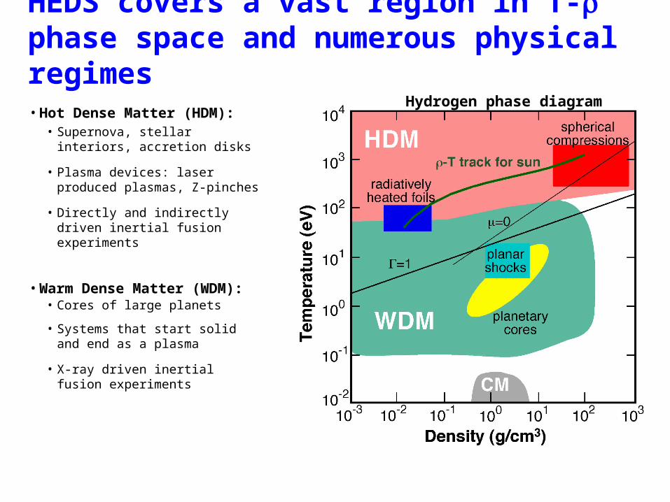
HEDS covers a vast region in T- phase space and numerous physical regimes•Hot Dense Matter (HDM):
• Supernova, stellar interiors, accretion disks
• Plasma devices: laser produced plasmas, Z-pinches
• Directly and indirectly driven inertial fusion experiments
•Warm Dense Matter (WDM):• Cores of large planets
• Systems that start solid and end as a plasma
• X-ray driven inertial fusion experiments
HED
WDM
Hydrogen phase diagram
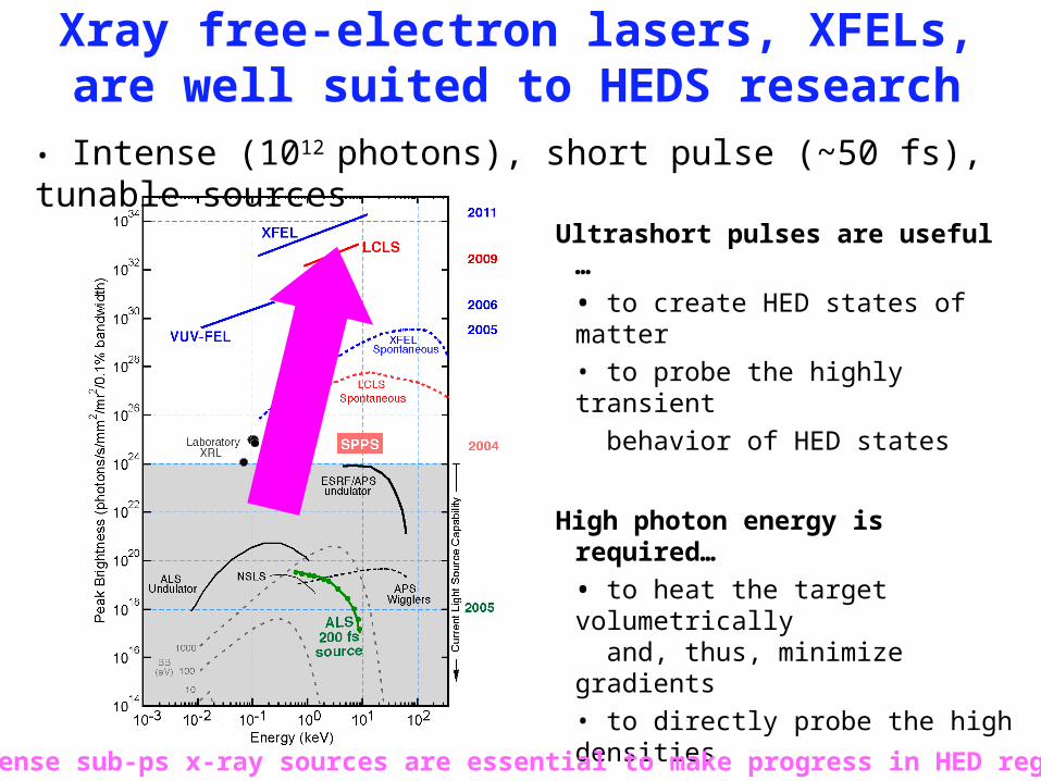
Xray free-electron lasers, XFELs, are well suited to HEDS research
Ultrashort pulses are useful …• to create HED states of matter• to probe the highly transient behavior of HED states
High photon energy is required…• to heat the target volumetrically and, thus, minimize gradients• to directly probe the high densities
High photon number is useful… • to make single-shot data feasible
Intense sub-ps x-ray sources are essential to make progress in HED regime
• Intense (1012 photons), short pulse (~50 fs), tunable sources
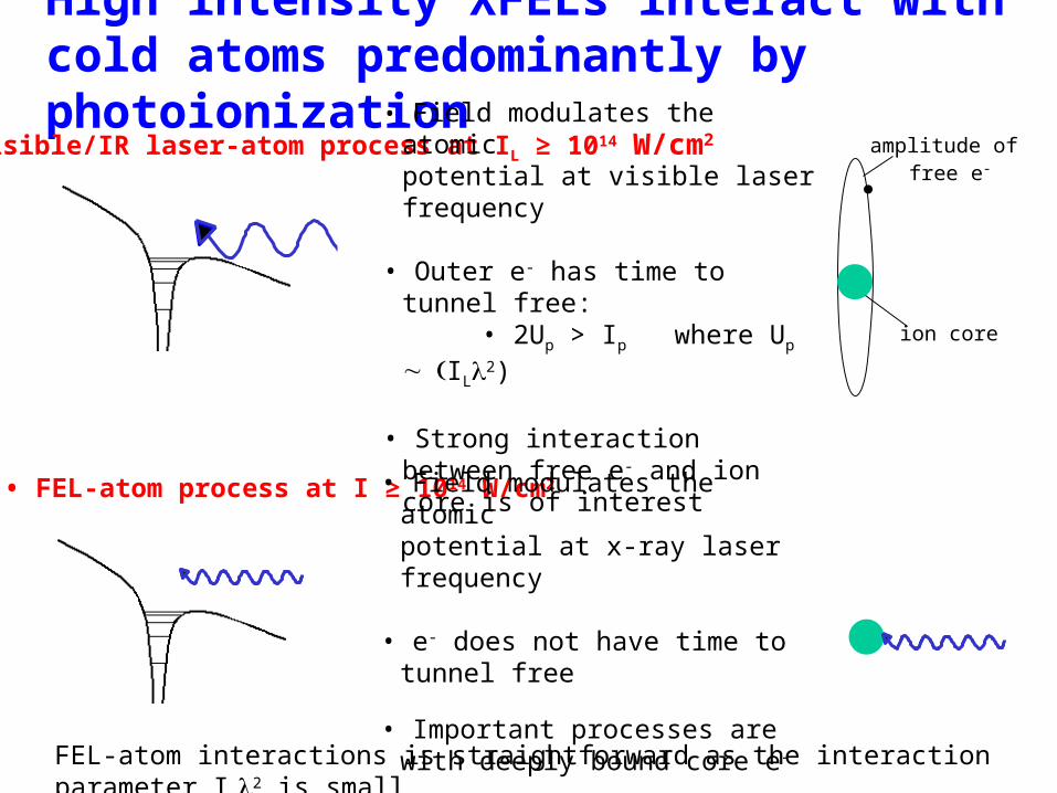
High intensity XFELs interact with cold atoms predominantly by photoionization
• Visible/IR laser-atom process at IL ≥ 1014 W/cm2 amplitude of free e-
ion core
• FEL-atom process at I ≥ 1014 W/cm2
• Field modulates the atomic potential at visible laser frequency
• Outer e- has time to tunnel free: • 2Up > Ip where Up
IL2)
• Strong interaction between free e- and ion core is of interest
• Field modulates the atomic potential at x-ray laser frequency
• e- does not have time to tunnel free
• Important processes are with deeply bound core e-FEL-atom interactions is straightforward as the interaction
parameter I 2 is small
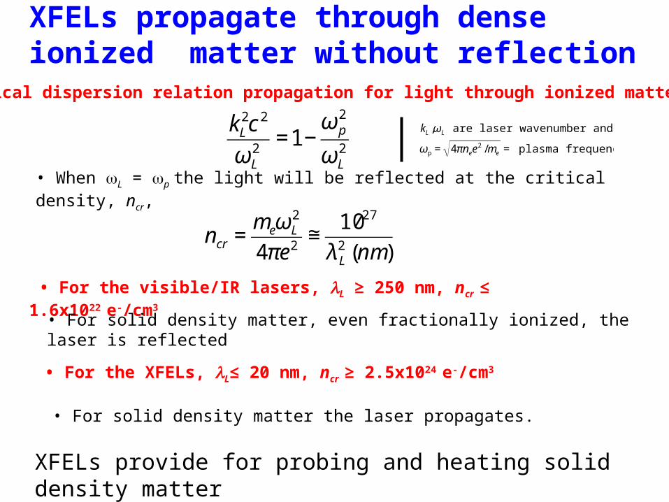
XFELs propagate through dense ionized matter without reflection
• Classical dispersion relation propagation for light through ionized matter :
• For the visible/IR lasers, L ≥ 250 nm, ncr ≤ 1.6x10²² e-/cm3
• When L = p the light will be reflected at the critical density, ncr,
XFELs provide for probing and heating solid density matter
€
kL2c 2
ωL2
=1−ωp
2
ωL2
€
ncr =meωL
2
4πe2≅
1027
λ L2 (nm)
€
kL ,ωL are laser wavenumber and frequency
ωp = 4πnee2 /me = plasma frequency
• For solid density matter, even fractionally ionized, the laser is reflected
• For the XFELs, L≤ 20 nm, ncr ≥ 2.5x1024 e-/cm3
• For solid density matter the laser propagates.
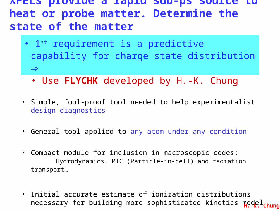
XFELs provide a rapid sub-ps source to heat or probe matter. Determine the state of the matter
• Simple, fool-proof tool needed to help experimentalist design diagnostics
• General tool applied to any atom under any condition
• Compact module for inclusion in macroscopic codes: Hydrodynamics, PIC (Particle-in-cell) and radiation transport…
• Initial accurate estimate of ionization distributions necessary for building more sophisticated kinetics model
• 1st requirement is a predictive capability for charge state distribution • Use FLYCHK developed by H.-K. Chung
H.-K. Chung
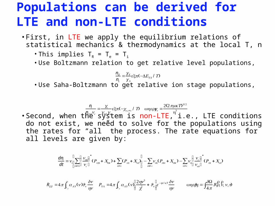
Populations can be derived for LTE and non-LTE conditions•First, in LTE we apply the equilibrium relations of statistical mechanics & thermodynamics at the local T, n
•This implies TR = Te = Ti
•Use Boltzmann relation to get relative level populations,
•Use Saha-Boltzmann to get relative ion stage populations,
•Second, when the system is non-LTE, i.e., LTE conditions do not exist, we need to solve for the populations using the rates for “all” the process. The rate equations for all levels are given by:
nU
nL
=gU
gL
exp(−ΔEUL / T)
ni
ni+1ne
=gi
gi+1ge
exp(−χi,i+i / T) wherege =2(2πmkT)3/ 2
h3
dni
dt=ni
ni''
ni
⎛
⎝⎜ ⎞
⎠⎟*
Rii'' + Ci''i( ) + Rii' +Cii'( )i'>i∑
i''<i∑⎡
⎣⎢
⎤
⎦⎥− ni'' Ri'' i +Ci''i( )− ni'
ni
nii'
⎛
⎝⎜ ⎞
⎠⎟*
Ri'i +Cii'( )i'>i∑
i''< i∑
RLU =4π α LU (ν )J ν
dνhνν o
∞
∫ RUL =4π αLU (ν)2hν3
c2+ J ν
⎡⎣⎢
⎤⎦⎥ν o
∞
∫ e−hν /kT dνhν
whereJ ν =dΩ4π
I (rr ,rn, ν,t)∫

New method to include EA and DR processes: 1st Essential element for FLYCHK
•EA/DR processes must be in detailed balance for collision-dominated plasmas
•EA/DR processes via autoionizing states are modeled within a hydrogenic formalism
Au
toio
niz
ing
(Ai)
st
ate
sB
oun d
Recombined ion
ground state Bo
und
sta
tes
of r
eco
mb
inin
g
ion
Δn=1
Δn=2
Δn=3
•Excitation following by Autoionization (EA) and its reverse process Dielectronic Recombination (DR) are critical in many kinetics problems
H.-K. Chung
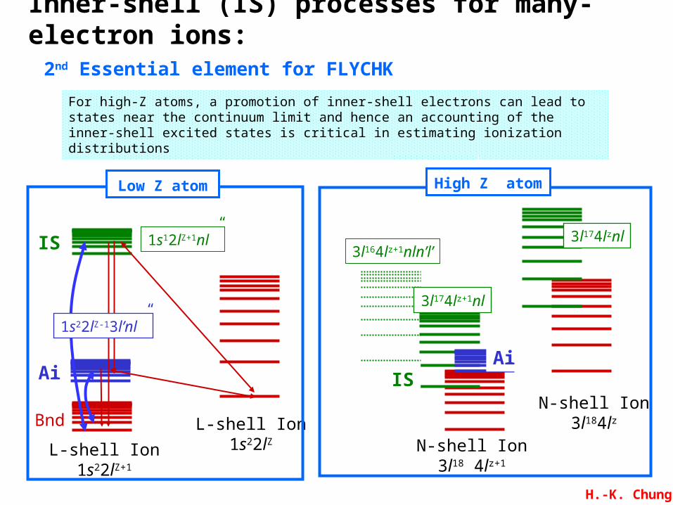
Inner-shell (IS) processes for many-electron ions: 2nd Essential element for FLYCHK
For high-Z atoms, a promotion of inner-shell electrons can lead to states near the continuum limit and hence an accounting of the inner-shell excited states is critical in estimating ionization distributions
N-shell Ion3l18 4lz+1
N-shell Ion3l184lz
3l174lznl3l164lz+1nln’l’
3l174lz+1nl
AiIS
High Z atom
L-shell Ion1s22lZ+1
L-shell Ion1s22lZ
1s12lZ+1nl”
Ai
IS
1s22lZ-13l’nl”
Bnd
Low Z atom
H.-K. Chung
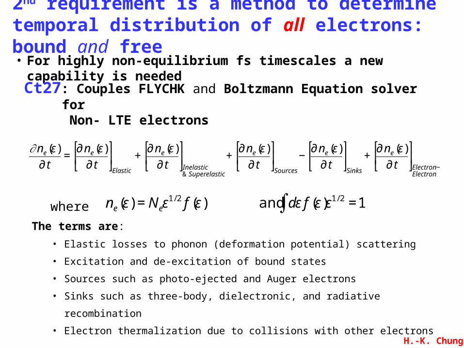
• For highly non-equilibrium fs timescales a new capability is needed
2nd requirement is a method to determine temporal distribution of all electrons: bound and free
H.-K. Chung
Ct27: Couples FLYCHK and Boltzmann Equation solver for Non- LTE electrons
The terms are:
• Elastic losses to phonon (deformation potential) scattering
• Excitation and de-excitation of bound states
• Sources such as photo-ejected and Auger electrons
• Sinks such as three-body, dielectronic, and radiative recombination
• Electron thermalization due to collisions with other electrons
€
ne (ε) = Neε1/ 2 f (ε) and dε∫ f (ε)ε1/ 2 =1wher
e€
∂ne (ε)
∂ t=
∂ ne (ε)
∂ t
⎡
⎣ ⎢
⎤
⎦ ⎥Elastic
+∂ ne (ε)
∂ t
⎡
⎣ ⎢
⎤
⎦ ⎥Inelastic& Superelastic
+∂ ne (ε)
∂ t
⎡
⎣ ⎢
⎤
⎦ ⎥Sources
−∂ ne (ε)
∂ t
⎡
⎣ ⎢
⎤
⎦ ⎥Sinks
+∂ ne (ε)
∂ t
⎡
⎣ ⎢
⎤
⎦ ⎥Electron −Electron
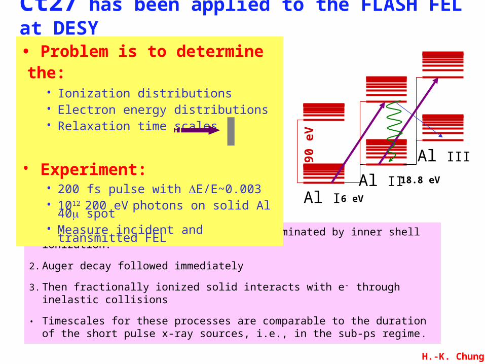
Ct27 has been applied to the FLASH FEL at DESY
1.Initially FEL-matter interaction is dominated by inner shell ionization.
2.Auger decay followed immediately
3.Then fractionally ionized solid interacts with e- through inelastic collisions
• Timescales for these processes are comparable to the duration of the short pulse x-ray sources, i.e., in the sub-ps regime.
• Problem is to determine the:• Ionization distributions• Electron energy distributions• Relaxation time scales
• Experiment:• 200 fs pulse with ΔE/E~0.003• 1012 200 eV photons on solid Al 40 spot
• Measure incident and transmitted FEL
Al IIAl I
Al III90 eV
18.8 eV
6 eV
H.-K. Chung
Electron energy (eV)
fe (
# /c c
/ eV
)
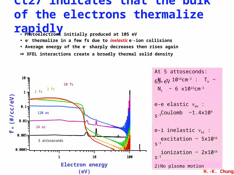
Ct27 indicates that the bulk of the electrons thermalize rapidly
• Photoelectrons initially produced at 105 eV • e- thermalize in a few fs due to inelastic e--ion collisions• Average energy of the e- sharply decreases then rises again
XFEL interactions create a broadly thermal solid density
0.0001
0.001
0.01
0.1
1
10
1 10 100
5 attoseconds
0.0001
0.001
0.01
0.1
1
10
1 10 100
24 as
0.0001
0.001
0.01
0.1
1
10
1 10 100
120 as
0.0001
0.001
0.01
0.1
1
10
1 10 100
1 fs
0.0001
0.001
0.01
0.1
1
10
1 10 100
3 fs
0.0001
0.001
0.01
0.1
1
10
1 10 100
10 fs
Assumptions
1) No initial solid-state structure
2) No plasma motion
At 5 attoseconds:
Ne ~ 1016cm-3 : Te ~ 65 eV
Ni ~ 6 x1022cm-3
e-e elastic νee :
Coulomb ~1.4x10⁹ s-1
e-i inelastic νei :
excitation ~ 5x10¹⁶ s-1
ionization ~ 2x10¹⁶ s-1
H.-K. Chung

With a sense that the electron distribution will be thermal one estimate the sample temperature
• For a 10x10x100 µm thick sample of Al
• Ensure sample uniformity by using only 66% of FEL beam energy
• Equating absorbed energy to total kinetic and ionization energy
• Find 10 eV at solid density at 4 Mb with ne = 2x1022 cm-3 and <Z> ~0.3
• Material, rapidly and uniformly heated, releases isentropically
E
V=32
neTe + nii∑ I p
i where Ipi = ionization potential of stage i -1
XFEL10 µm
100 µm
solid sample short pulse probe laser
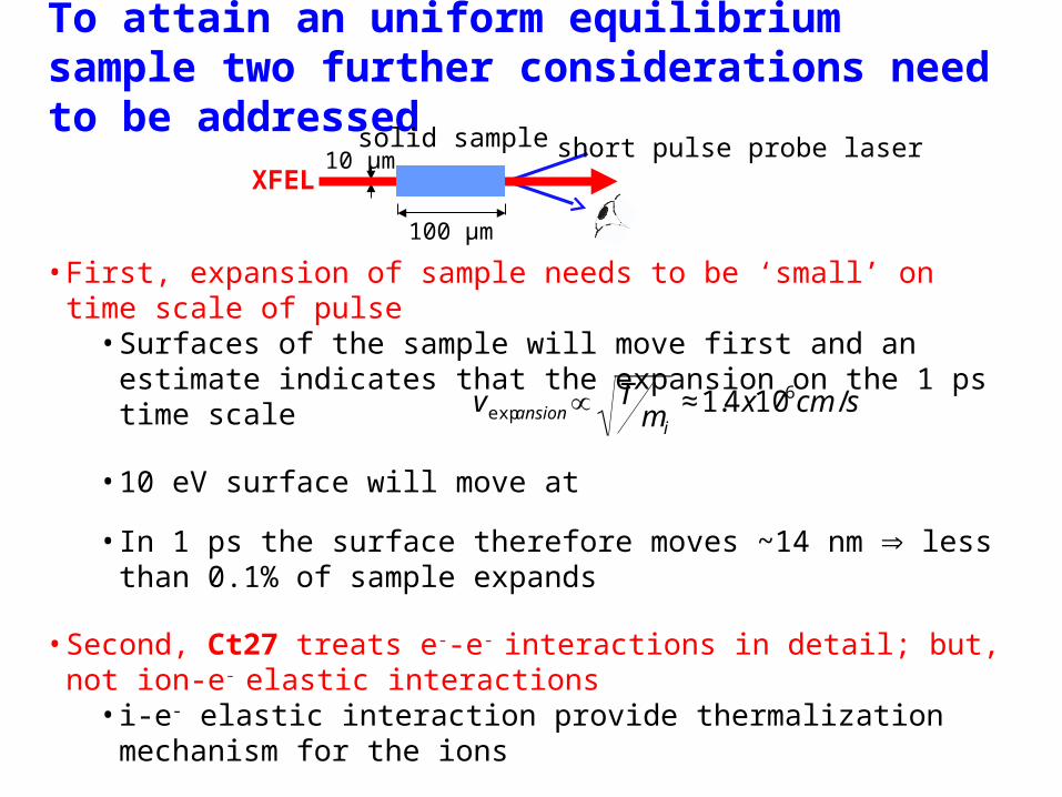
To attain an uniform equilibrium sample two further considerations need to be addressed
•First, expansion of sample needs to be ‘small’ on time scale of pulse•Surfaces of the sample will move first and an estimate indicates that the expansion on the 1 ps time scale
•10 eV surface will move at
•In 1 ps the surface therefore moves ~14 nm less than 0.1% of sample expands
•Second, Ct27 treats e--e- interactions in detail; but, not ion-e- elastic interactions•i-e- elastic interaction provide thermalization mechanism for the ions
•Compared to e--e- thermalization time, the i-e- will be reduced by ~me/mi
•For the example one estimates Ti to equal Te in ~3 ps
100 µm
XFEL10 µm
solid sample short pulse probe laser
€
vexp ansion ∝ Tmi
≈1.4x106cm /s
c la s s ic a l p la s m a
d e n s e
p la s m a
Γ =1
Γ =1 0
Density(g/cm3)
103
104
101
102
102 104100
10-4 10-2 1
Γ =1 0 0
h ig h
d e n s ity
m a tte r
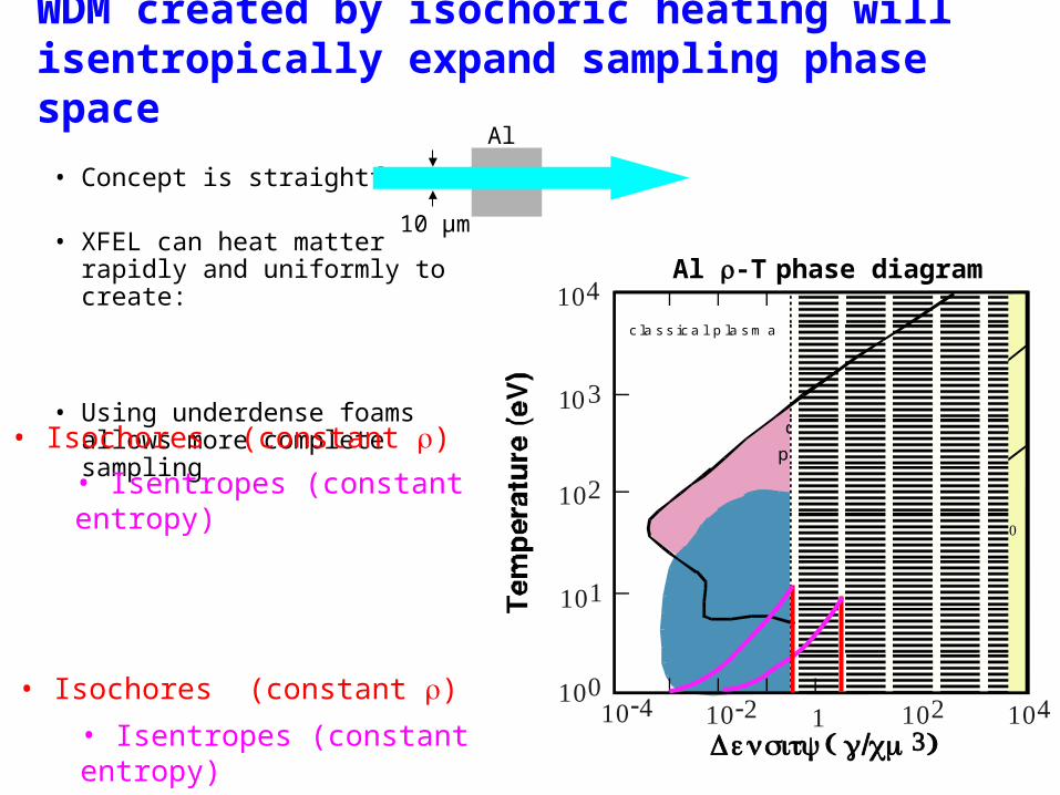
WDM created by isochoric heating will isentropically expand sampling phase space
• Concept is straightforward
• XFEL can heat matter rapidly and uniformly to create:
• Using underdense foams allows more complete sampling
Al
10 µm
Al -T phase diagram
• Isochores (constant )• Isentropes (constant entropy)
• Isochores (constant )• Isentropes (constant entropy)
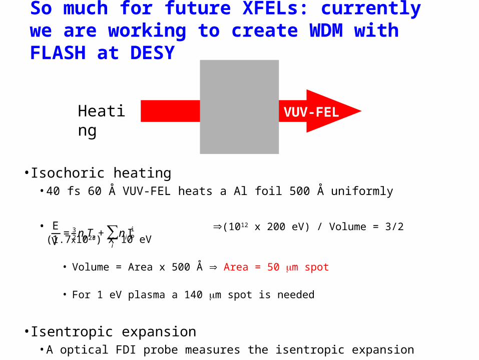
So much for future XFELs: currently we are working to create WDM with FLASH at DESY
•Isochoric heating•40 fs 60 Å VUV-FEL heats a Al foil 500 Å uniformly
• (1012 x 200 eV) / Volume = 3/2 (1.7x1023) x 10 eV
• Volume = Area x 500 Å Area = 50 m spot
• For 1 eV plasma a 140 m spot is needed
•Isentropic expansion•A optical FDI probe measures the isentropic expansion
€
EV
=32neTe+ niIP
i
i
∑
Heating
500 Å Al
VUV-FEL

Simulations of FLASH VUV-FEL confirm simple estimates for creating WDM:
•500 Å Al irradiated by split FLASH with 200 fs pulse width
•Temperature and density at end of the FLASH pulse
140 µm spot 30 µm spot
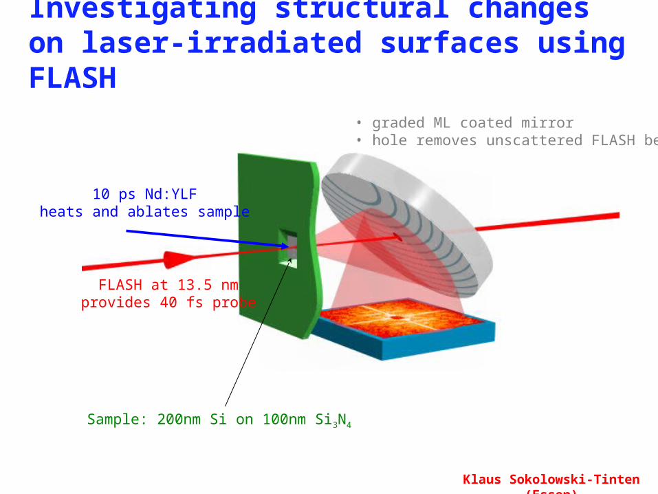
Investigating structural changes on laser-irradiated surfaces using FLASH
10 ps Nd:YLFheats and ablates sample
FLASH at 13.5 nmprovides 40 fs probe
Sample: 200nm Si on 100nm Si3N4
• graded ML coated mirror• hole removes unscattered FLASH beam
Klaus Sokolowski-Tinten (Essen)

-10 ps 15 ps 40 ps 140 ps
340 ps 840 ps 1.1 ns 1.35 ns
1.85 ns 4.5 ns
Klaus Sokolowski-Tinten
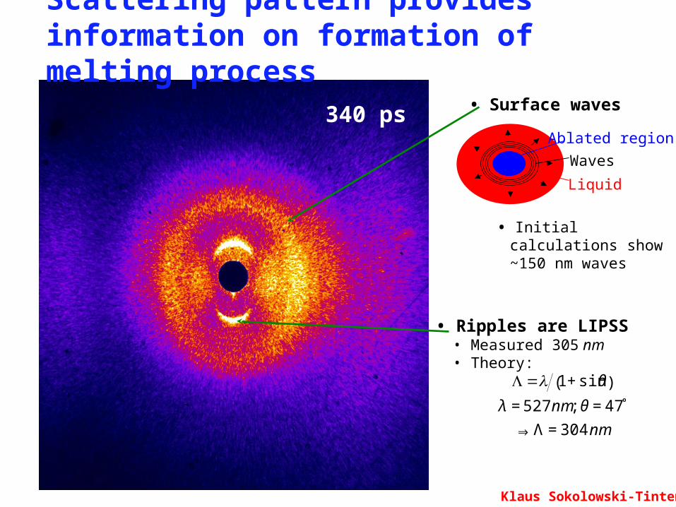
340 ps
Scattering pattern provides information on formation of melting process
• Ripples are LIPSS• Measured 305 nm• Theory:
• Initial calculations show ~150 nm waves
• Surface waves
€
Λ= 1+ sinθ( )
λ = 527 nm; θ = 47̊
⇒ Λ = 304 nm
Ablated region
Waves
Liquid
Klaus Sokolowski-Tinten

XFEL will probe WDM & high pressure states
Particle
data Free
e-Te
-300-200-100 0 100
LFCSLFCRPA Shift
Bound e-
Energy shift (eV)
• Short pulse freezes motion• High flux yields single shot data• High brightness probes “low-symmetry”• High energy tunability accesses “thick” targets
LCLS
•Low Divergence nm-scale fs diffraction of real solids (J. Wark, Oxford)
Standard techniques
XFEL techniques
• Bragg lattice compression and phase change
•Diffuse dislocation content and lattice disorder
•Small-angle sub-micron defect scattering
Shock front
Interface
CHAl
•X-ray Thomson Scattering T, Ne,
•Phase-Contrast imaging nm scale images (D. Hicks, LLNL)
1013 < 108 ~ 109
Warm Dense Matter and
Free-Electron Lasers
QuickTime™ and aTIFF (Uncompressed) decompressorare needed to see this picture.
QuickTime™ and aTIFF (Uncompressed) decompressorare needed to see this picture.
A. Nelson1, S. Toleikis2, R. Sobierajski3, P. Heimann4,
B. Nagler5, M. Koslova6, T. Whitcher5, L. Juha6, F. Khattak7,
J. Krzywinski2, J. Wark5, K. Sokolowski-Tinten8, M. Fajardo9,
P. Zeitoun10, P.Mercere11, D. Riley7, T. Tschentscher2,
R. Faeustlin2, D. Schneider4, T. Schenkel4, S. Bajt1, H. Chung1,
S. Moon1, H. Scott1, H. Chapman1, …, R. W. Lee1
1 Lawrence Livermore National Laboratory, Livermore, CA USA2 Deutsches Elektronen-Synchrotron DESY, Hamburg, Germany3 Instytut Fizyki Polskiej Akademii Nauk, Warsaw, Poland4 Lawrence Berkeley National Laboratory, Berkeley, USA
5 Oxford University, Oxford UK6 Academy of Sciences, Prague, Czech Republic7 Queen's University of Belfast, Belfast UK
Universitat Duisburg Essen , Duisberg, Germany9Instituto Superior Tecnico, Lisbon Portugal
10ENS Techniques Avancées, Paris, France11Synchrotron Soleil, Gif-sur-Yvette, France
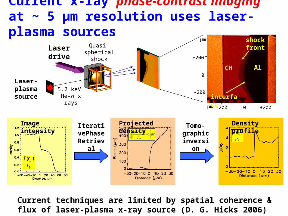
Current x-ray phase-contrast imaging at ~ 5 µm resolution uses laser-plasma sources
dzzr
∫ ⎟⎟⎠
⎞⎜⎜⎝
⎛−⊥ 1
),(
0
0
)(
⊥r
0
)(
I
rI ⊥
Current techniques are limited by spatial coherence & flux of laser-plasma x-ray source (D. G. Hicks 2006)
IterativePhase
Retrieval
Tomo-graphic
inversion
Projected density Density profileImage intensity
Laser drive
Laser-plasma source
Quasi-spherical shock
5.2 keV He-α x rays
+200
-200
0
+2000-200
µm
µm
shock front
interface
CH Al
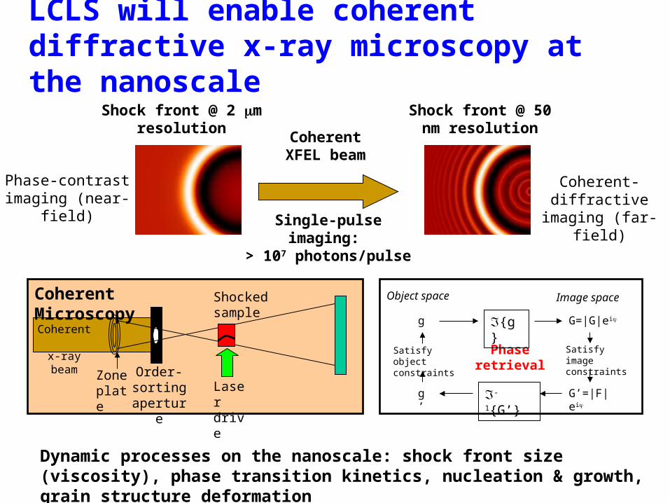
LCLS will enable coherent diffractive x-ray microscopy at the nanoscale
Dynamic processes on the nanoscale: shock front size (viscosity), phase transition kinetics, nucleation & growth, grain structure deformation
Coherent XFEL beam
Shock front @ 2 m resolution
Shock front @ 50 nm resolution
Phase-contrast imaging (near-field)
Coherent-diffractive imaging (far-field)
Coherent x-ray beam
Zone plate
Order-sorting
aperture
Shocked sample
Laser drive
Coherent Microscopy
Single-pulse imaging: > 107 photons/pulse
Phase retrieval
g
Satisfy image constraints
G=|G|ei{g}
Satisfy object constraints
G’=|F|eig’ -1{G’}
Object space Image space

MD simulations of Ta show nucleation and solidification the XFEL can probe
Uniform speckleNon-uniformity of speckle
Higher intensity spots number, size, & form of
clusters• Goal of in situ x-ray diffraction of shocked solids at granular level is to understand the microscopic to inform mesoscopic, and then macroscopic
• Study how individual grains respond elastically and plastically to high pressure as a function of orientation with respect to a given uniaxial shock wave
• XFEL is ideally suited to probe via diffraction polycrystalline high pressure solids because it is an ultra-bright, non-diverging, monochromatic source.
(Streitz et al.)
(Belak)
50 nm cube16M atoms
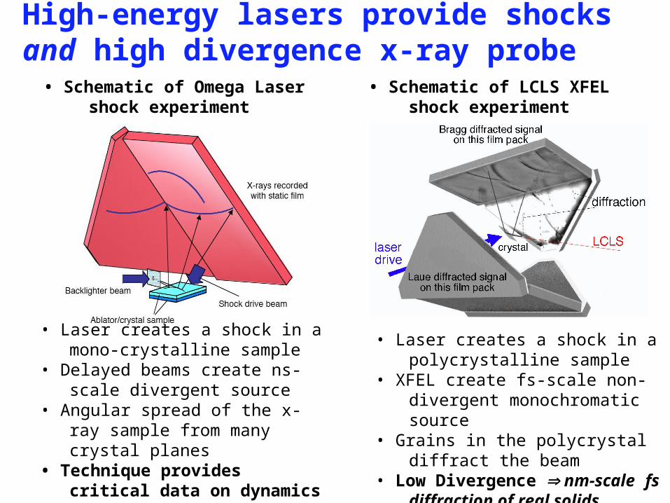
High-energy lasers provide shocks and high divergence x-ray probe
• Schematic of Omega Laser shock experiment
• Schematic of LCLS XFEL shock experiment
• Laser creates a shock in a mono-crystalline sample
• Delayed beams create ns-scale divergent source
• Angular spread of the x-ray sample from many crystal planes
• Technique provides critical data on dynamics at high pressure
• Laser creates a shock in a polycrystalline sample
• XFEL create fs-scale non-divergent monochromatic source
• Grains in the polycrystal diffract the beam
• Low Divergence nm-scale fs diffraction of real solids

XFEL via photoionization pumping provides interesting WDM diagnostic potential• Scattering from free electrons provides a measure of the Te, ne, f(v), and plasma damping (S. Glenzer)
structure alone not sufficient
for plasma-like matter
• Due to absorption, refraction and reflection neither visible nor laboratory x-ray lasers can probe high density little to no high density
data
• FEL signals will be well above noise for all HED matter
Al Scattering and absorption
10-2
10-1
100
101
102
103
104
Absorption or Scattering Length (1/cm)
2015105
Photon Energy (keV)
Photo-absorption
Scattering
Rayleigh - coherent Thomson - incoherent bound electrons Thomson - incoherent free electrons
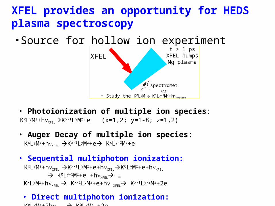
XFEL provides an opportunity for HEDS plasma spectroscopy
•Source for hollow ion experiment
0.1 µm CH
25 µm Mg
Visiblelaser
t = 0 laser irradiates CH with Mg
dot
• Photoionization of multiple ion species: KxLyMz+hνXFELKx-1LyMz+e (x=1,2; y=1-8; z=1,2)
• Auger Decay of multiple ion species: KxLyMz+hνXFEL Kx-1LyMz+e KxLy-2Mz+e
• Sequential multiphoton ionization: KxLyMz+hνXFEL Kx-1LyMz+e+hνXFELK0LyMz+e+hνXFEL
K0Ly-1Mz+e +hνXFEL … KxLyMz+hνXFEL Kx-1LyMz+e+hνXFEL Kx-1Ly-2Mz+2e
• Direct multiphoton ionization: KxLyMz+2hνXFEL K0LyMz +2e
XFEL
spectrometer
t > 1 ps XFEL pumps Mg plasma
• Study the K0LyMz K1Ly-1Mz+hνemitted
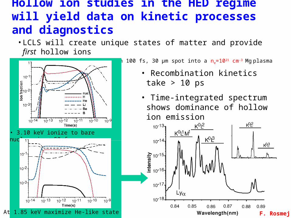
Hollow ion studies in the HED regime will yield data on kinetic processes and diagnostics•LCLS will create unique states of matter and provide first hollow ions •Simulations: 5x10¹⁰ photons in 100 fs, 30 µm spot into a ne=1021 cm-3 Mg
plasma • Recombination kinetics take > 10 ps
• Time-integrated spectrum shows dominance of hollow ion emission
• At 1.85 keV maximize He-like state
• 3.10 keV ionize to bare nucleus in < 50 fs
F. Rosmej

In Warm Dense Matter regime the hollow ions provide time-resolved diagnostic information
•XFEL forms unique states and provides in situ diagnostics with ~100 fs resolution
• 5x10¹⁰ 1.85 keV photons in 30 µm spot into a ne=1023 cm-2 plasma• Strong coupling parameter, Γii = Potential/Kinetic Energy ~ 10
• Spectra vary with temperature • At high ne emission lasts ~100 fs
H.-K. Chung

Finally, saturating the continuum using FLASH may provide a ~100 fs absorption source•He-like B plasma at 30 eV, 5x1022 cm-3, 1 mm in length•FEL tuned to H-like boron 1-2 transition at 250 eV
Opacity and Emissivity Continuum rises rapidly and last for ~100 fs
H.-K. Chung

Summary of HEDS using sub-ps intense x-ray sources - XFELs• For both the hot and warm dense matter regimes new possibilities opened up by XFELs
• For WDM the FELs provide• WDM creation: Fast uniform heating source• WDM diagnostics: Thomson Scattering, Kα temperature measurement, sub-ps absorption sources, phase contrast imaging, diffraction for high pressure states
• For HDM the FELs provide:(not shown)• Fast deposition may create hot, high pressure matter• Plasma spectroscopic probes of kinetic and radiative processes
• Diagnostic potential: Thomson scattering
High Energy Density Physics is an international journal covering original experimental and related theoretical work studying the physics of matter and radiation under extreme conditions. ‘High energy density’ is understood to be an energy density exceeding ~1011 J/m3. The editors and the publisher are committed to provide this fast-growing community with a dedicated high-quality channel for their original findings.
Papers suitable for publication in this journal cover topics in both the warm and hot dense matter regimes, such as laboratory studies relevant to non-LTE kinetics at extreme conditions, planetary interiors, astrophysical phenomena, inertial fusion and includes studies of, for example, material properties and both stable and unstable hydrodynamics. Developments in associated theoretical areas, for example the modelling of strongly coupled, partially degenerate and relativistic plasmas, are also covered.
Editorial Board:• Stefano Atzeni - Universita di Roma, Italy• James Bailey - Sandia National Laboratories, USA• John Barnard - LBNL, USA• Riccardo Betti - University of Rochester, USA• Todd Ditmire - University of Texas, USA• Mike Dunne - Rutherford Appleton Laboratory, UK• Javier Honrubia - Universidad Politecnica, Madrid• David Kilcrease - LANL, USA• Ryosuke Kodama - Osaka University, Japan• Michel Koenig - Ecole Polytechnique, France• Roberto Mancini - University of Nevada, USA• Edward Moses - LLNL, USA• Michael S. Murillo - LANL, USA• Patrick Renaudin - CEA/DAM Ile de France, France• Frank Rosmej - Université Pierre et Marie Curie, France• Markus Roth - Technische Universitat Darmstadt, Germany• Damian Swift - LANL, USA• Thomas Tschentscher - HASYLAB at DESY, Germany• Justin Wark - Oxford University, United Kingdom• Jie Zhang - Chinese Academy of Sciences, China
www.elsevier.com/locate/hedp
Motivations for High Energy Density Physics
• Cross-disciplinary studies can be aired •In HEDP, a research area incorporating several fields, it is essential to provide a forum for discussion.
• Venue for the discussion of innovative ideas•With the rapid expansion of HEDP research into new experimental and theoretical areas is critical.
• Promotion of the broad-based interests of the field•With its boundaries still being defined, HEDP can assist in focusing attention on issues related to “definition”.
• Papers can delve into why, e.g., certain strongly coupled systems are not interesting, while others with similar strong-coupling parameters are intriguingly difficult.
• Provision of a scientific outlet for rejuvenation•Older methods, when applied to new HEDP processes, can become important again and HEDP is an scientific outlet for that rejuvenation
The End
z
x
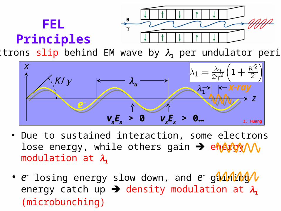
FEL Principles
• Due to sustained interaction, some electrons lose energy, while others gain energy modulation at 1
• e losing energy slow down, and e gaining energy catch up density modulation at 1 (microbunching)
• Microbunched beam radiates coherently at 1, enhancing the process exponential growth of radiation power
K/1
u
ex-ray
vxEx > 0
• Electrons slip behind EM wave by 1 per undulator period (u)
vxEx > 0… Z. Huang
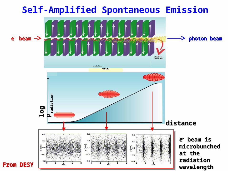
Self-Amplified Spontaneous Emission (SASE)
distancedistance
undulatorundulator
ee beam is beam is microbunched microbunched at the radiation at the radiation wavelengthwavelength
From DESYFrom DESY
photon beamphoton beamee-- beam beamlo
g P
log
Pra
dia
tio
n

Magnetic Bunch Compression
z0
Δ
zz
under-compression
V = V0sin()
RF AcceleratingRF AcceleratingVoltageVoltage
RF AcceleratingRF AcceleratingVoltageVoltage
Δz = R56Δ
Path Length-EnergyPath Length-EnergyDependent BeamlineDependent Beamline
Path Length-EnergyPath Length-EnergyDependent BeamlineDependent Beamline
…or over-compression
ΔΔ
zz
E/E
Δ
z
‘chirp’
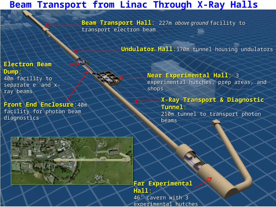
Beam Transport from Linac Through X-Ray Halls
Beam Transport HallBeam Transport Hall: : 227m 227m above ground above ground facility to transport electron beamfacility to transport electron beam
Undulator HallUndulator Hall::170m tunnel housing undulators170m tunnel housing undulators
Near Experimental HallNear Experimental Hall: : 3 experimental hutches, 3 experimental hutches, prep areas, and shopsprep areas, and shops
X-Ray Transport & Diagnostic TunnelX-Ray Transport & Diagnostic Tunnel::210m tunnel to transport photon beams210m tunnel to transport photon beams
Far Experimental HallFar Experimental Hall::46’ cavern with 3 experimental 46’ cavern with 3 experimental hutches and prep areashutches and prep areas
Electron Beam DumpElectron Beam Dump::40m facility to separate e40m facility to separate e-- and x-ray beamsand x-ray beams
Front End EnclosureFront End Enclosure::40m facility for 40m facility for photon beamphoton beam diagnosticsdiagnostics
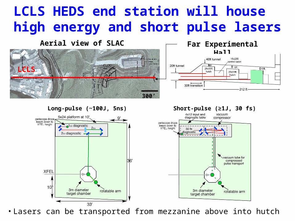
LCLS HEDS end station will house high energy and short pulse lasers
•Lasers can be transported from mezzanine above into hutch
Far Experimental Hall
Aerial view of SLAC
300’
LCLS
Long-pulse (~100J, 5ns) Short-pulse (≥1J, 30 fs)