heavy earth moving equipment
TRANSCRIPT
1Heavy Earth Moving Equipment
1.1. INTRODUCTION TO CONSTRUCTION EQUIPMENTAs we know, construction activity is an integral part of a country�s
infrastructure and industrial development. It includes buildings suchas hospitals, educational institutions, townships, offices, commercialcomplexes, etc.; urban infrastructure such as water supply, sewerage,drainage etc.; highways, flyovers, tunnels, ports, railways, airports;power systems; irrigation and agriculture systems; telecommunications,industrial plants.
Construction has become the basic input for socio-economicdevelopment. Besides, the construction industry generates substantialemployment and provides a growth impetus to other sectors throughbackward and forward linkages.
The upswing in the Indian Economy has enhanced the demandfor the construction and material handling equipments. The demand forconstruction and material handling equipments is correlated with thegrowth of other segments. Prior to 1960�s, domestic requirements ofconstruction equipment were entirely met by the imports.
Domestic production in India began in 1964 with the start ofmanufacturing of bulldozers, scrapers, dumpers, graders etc. by BharatEarth Movers Ltd. (BEML), a Public Sector Underdating. In privatesector, the Hindustan Motors established its Earthmoving EquipmentDivision in 1969. Thereafter L & T in 1974 began to manufacturehydraulic excavators under license from Poclain. In 1980�s and 1990�sseveral other private sector undertakings entered in the field, whilemany companies started as Joint Ventures with global players.
During last 3 to 4 decades, construction industry has madeenormous progress and has grown both in terms of size and diversity.The construction and mining industry are the primary users of the heavyearthmoving equipments in India. The organised construction sectoraccounts for about 55% of the total construction equipment industry.
1
CONSTRUCTION EQUIPMENT AND MANAGEMENT2
Construction equipment plays a significant role in the executionof modern high cost time-bound construction projects. These produceoutput at accelerated speed, and enables completion of tasks in a limitedtime. The equipment saves manpower which is becoming scarce, costlyand more demanding day-by-day. In addition, equipment improvesproductivity, quality and safety. Thus the construction equipment havebecome indispensble item of resources and their role continues to growsteadily.
This book concenetrates on the engineering fundamentals forplanning, selection, and utilization of construction equipment. The bookalso describes the basic operational characteristics of different types ofconstruction equipments. It also explains the fundamental concepts ofmachine utilization, which economically match machine capability tospecific project construction requirements.
In most cases, a piece of equipment does not work as a stand-aloneunit. Pieces of different types of equipment work in groups, thereforethe optimization in the management of an equipment spread is criticalfor a contractor, both in achieving a competitive pricing position and forarranging the capital required to finance the project.
The project planner/engineer on the job is required to match theright machine or combination of machines to the job at hand.For thispurpose, he is required to identify the construction equipment forexecuting the project tasks, assessing equipment performance capability,forecasting date wise requirement of numbers and types of equipment,and then selecting the equipment to be acquired.
The production tasks which can be performed with equipmentinclude excavating, hauling transporting, compacting, grading, hoisting,concreting, precasting, trenching, pipe-laying etc. In addition, thesupport equipment are also required, at the project site, which includegenerators, compressors, pumping sets and other utility servicesequipment.
The proper emphasis is required to be given by the equipmentengineer on reduction of down-time, achieving optimum utilization,increase in production at minimum cost through right selection andmanagement of these equipment. He is expected to coordinate withvarious wings of the project in discharging his job of equipment planning,balancing, selection of equipment, its deployment, personnel selectionand training, preventive maintenance etc.
1.2. CLASSIFICATION OF CONSTRUCTION EQUIPMENTConstruction equipments can be broadly classified on the basis
of their functions as under:1. Earthwork Equipments(i) Earth cuting and moving equipment : Bulldozers, Scrapers,
Front-end loaders, Motor graders.
HEAVY EARTH MOVING EQUIPMENT 3
(ii) Excavation and lifting equipment : Backhoes, Power Shovels,Draglines, Clamshells.
(iii) Loading equipment : Loaders, Shovels, Excavators.
(iv) Transportation equipmnt : Tippers, Dump Trucks, Scrapers,Conveyors.
(v) Compacting equipment : Tamping Foot Rollers, Smooth WheelRollers, Pneumatic Rollers, Vibratory Rollers, PlateCompactors.
2. Concreting Plant and Equipments(i) Production equipment : Batching Plants, Concrete Mixers.
(ii) Transportation equipment : Truck mixers, Concrete dumpers.
(iii) Placing equipment : Concrete pumps, Conveyors, Hoists,Grouting equipment.
(iv) Concrete Vibrating equipment : Needle vibrators, Platecompactors.
3. Material Hoisting Equipments(i) Hoists : Fixed, Mobile, Fork-lifts.
(ii) Mobile Cranes : Crawler-mounted, self-propelled rubber-tyred,truck-mounted.
(iii) Tower Cranes : Stationary, Travelling type.
4. Special Purpose Heavy Construction Plant andEquipments
(i) Aggregate production equipment : Crushing plants, Rockblasting equipment, Screening plants.
(ii) Concrete paving equipment : Concrete paver finishers.
(iii) Pile driving equipment : Pile driving hammers.
(iv) Asphalt mix production and Placement equipment : Asphaltplants, asphalt pavers.
(v) Tunneling equipment : Drill jumbos, Muck-hauling equipment,Rock bolters, Tunnel boring machines.
5. Support and Utility Services Equipment(i) Pumping and Dewatering equipment.
(ii) Pipe laying equipment.
(iii) Generators. (iv) Welding equipment.
1.3. INTRODUCTION TO HEAVY EARTH MOVING EQUIPMENTS
Modern mechanised earthmoving really started when the crawlertractor was adopted from its agricultural antecedent. To meet the
CONSTRUCTION EQUIPMENT AND MANAGEMENT4
growing demand of minerals particularly coal, the earthmovingequipment was first introduced in 1940�s in open-cast coalmines in ourcountry. Shovels of about 2.2 cum capacity with dumpers of 12 to 15tonnes capacity were introduced in these mines. Bhakra Nangal Damstarted in 1950�s used higher capacity and sophisticated earthmovingequipment like dozers, scrapers, shovels, draglines and dumpers. Almostsame time in 1950�s shovels of 1.5 to 2.5 m3, front-end loaders, dozerswith rippers, and 15 to 25 tonnes dumpers were introduced in iron oremines, replacing manual minining and locomotive traction. With theintroduction of heavy earthmoving equipment, bigger size operationswere taken up in construction of Hydel dams, irrigation schemes, coaland metal mining. Kudremukh Iron Ore Project in late 1970�s used 15cu m shovels, 120 tonnes diesel engine dumpers, 15 cu m front-endloaders and dozers of over 600 H.P.
The equipment of various sizes used for various projects wereimported from various countries. The indigenous manufacturers in thecountry are now planning to manufacture 10-12.5 m3 shovels, 85-120tonnes dumpers, about 450 H.P. class dozers, 30 m3 scrapers, 30 m3/90m draglines etc. With indigenous manufacature, it will save high costof importation and also help in standardisation which will solve theproblems of spare parts stocking, maintenance and downtime.
With the application of heavy earthmoving euipment (H.E.M.),production of coal has increased from 25 million tonnes to 570 milliontonnes, of iron ore from 3 million tonnes to 150 million tonnes, similarlyHydel power has also increased manifolds in last 30 years. All theseactivities involve movement of rock, earth, and minerals in such a hugequantities that these works of irrigation, hydel, and mining (coal andmineral) projects can not be undertaken manually within the timeschedule set for the projects.
Types of Earth Moving EquipmentsEarth Moving Equipments can be classified into following two
types :
(i) Production Equipment. Equipment used for digging,moving the material to the site of construction (may be dam, irrigationproject, road project, mining project or building construction project) orto the crushing plant.
(ii) Service Equipment. These are for the help of mainproduction equipment to achieve optimum capacity. For small worksdozers can be used as productive equipment. Motor Grader is used asproduction equipment in road construction projects, while it is used asservice equipment for keeping proper gradient of service road for dams,mines, and quarries.
HEAVY EARTH MOVING EQUIPMENT 5
1.4. TRACTORSTractors are the machines which change energy of the engine into
tractive energy. The tractors are primarily used to pull or push loads,butthey are also used for mounting many types of accessories like, bulldozerblades, rippers, front end shovels, hoes, draglines, clamshells, trenchers,winches, side booms, frontend bucket loaders, pipe layers etc.
As mentioned above, the tractor is a basic equipment and availablein two types ; namely (i) crawler or track type, and (ii) Rubber-tired orwheel-type. The tractor is a multi-purpose machine, light models ofwhich are used for agricultural or short haulage works, whereas heavymodels are employed for earth moving works, cranes, shovels or specialrigs. Wheeled units are employed for light but speedy jobs, whereascralwer units are rugged machines and are used for heavy duty works,where more tractive power is required.
Tractor ConstructionMain constituents of a tractor are : Engine, clutch, transmission
system, ground drive and controls.A diesel engine is generally used as prime mover and mounted
on the tractor frame and delivers the power through a clutch to the mainpower shaft. The power is transmitted from the engine to the final drivethrough engine clutch, torque convertor, change speed gear boxtransmission to rear differential and then finally to the rear drive axle.The drive is also transmitted through front differential to the front axle.
Engine clutch is provided to disconnect the engine from the restof the transmission system so that gears can be changed to change thespeed of the tractor. Care should be taken while changing the gears thatthe engagement of the clutch should be gradual to avoid undue strainon the surfaces of the clutch plates. The clutch control in small andmedium sized tractors is through pedal like that of a truck, but in largetractors it is through lever operated by hand.
Transmission system provides speed reduction and multiplicationof torque of the engine shaft, since final drive needs a high torque atlow speed. The reduction in speed is done by means of a change speedgear box. Now-a-days torque conerters are also used for the purpose. Thepower is then given to the drive axle through the differential, whichchanges the direction of the drive to 90° by using bevel gears and alsoreduces the speed upto some extent. Differential also facilitate insteering. As tractor changes its direction, one of the rear wheels musttravel faster than the other, and this is achieved by the diferential. Inthe wheeled tractor the steering is done through the front wheel. Theouter ends of the two half shafts carry pinions which mesh with largergears of the final drive, resulting variation in speed when the tractor istaking a turn. The change in the speeds of the track is made directly bystopping power supply to one, while the other continues to rotate.
CONSTRUCTION EQUIPMENT AND MANAGEMENT6
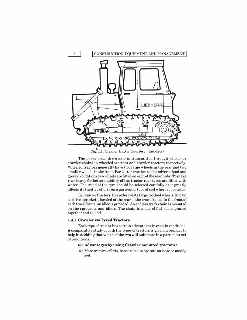
Fig. 1.1. Crawler tractor (courtesy : Liebherr)
The power from drive axle is transmitted through wheels orcrawler chains in wheeled tractors and crawler tractors respectvely.Wheeled tractors generally have two large wheels in the rear and twosmaller wheels in the front. For better traction under adverse load andground conditions two wheels are fitted on each of the rear hubs. To makerear heavy for better stability of the tractor rear tyres are filled withwater. The tread of the tyre should be selected carefully as it greatlyaffects its tractive efforts on a particular type of soil where it operates.
In Crawler tractors, live axles rotate large toothed wheels, knownas drive sprockets, located at the rear of the track frame. In the front ofeach track frame, an idler is provided. An endless track chain is mountedon the sprockets and idlers. The chain is made of flat shoes pinnedtogether end-to-end.
1.4.1. Crawler v/s Tyred TractorsEach type of tractor has certain advantages in certain condtions.
A comparative study of both the types of tractors is given hereunder tohelp in deciding that which of the two will suit more in a particular setof conditions.
(a) Advantages by using Crawler mounted tractors :(i) More tractive efforts, hence can also operate on loose or muddy
soil.
HEAVY EARTH MOVING EQUIPMENT 7
(ii) In absence of tyres, can easily operate in rocky conditions, asthere is no danger for the damage of the tyres.
(iii) Where maintenance of haul roads is difficult, it can easilytravel, specially in rough terrains.
(iv) Crawler tractors are more compact and powerful and hencecan handle difficult jobs as well.
(v) Greater floatation because of the lower pressure under thetracks.
(b) Advantages by using wheel-mounted tractors :(i) Can travel at higher speeds during the operation and also from
one job to another.
(ii) Ease in operation. Operator feels less fatigue.
(iii) Can travel on paved roads without damaging them.
(iv) Can travel long distances at its own power, whereas Crawlermounted needs trailers.
(v) When work is spread over long area, these are found to beproducing more output.
(vi) Operation, maintenance and repair costs less in wheeledtractors as compared to Crawler tractors. As large number oftrack parts are subjected to more wear.
(vii) Initial cost of the Crawler tractor is higher than the wheeledtractors, due to expensive track system.
(viii) Easy to manoeuvre.
Dozer SpecificationsAt the time of purchasing of dozens following points should be
clearly specified after examining the exact job requirements and themanufacturer�s limitations.
Engine horsepower at the flywheel, total operating weight, speedrange in various gear positions ; blade type and size and also maximumtilt position or angle position; number, type and size of rippers; turningradius, fuel tank capacities. In case of wheel dozer also mention, numberand sizes of the tyres, wheel base, ground clearance etc.
Following main factors should be considered while selecting atractor dozer :
(i) Size of the dozer for a given job.
(ii) The type of work expected from the tractor dozer e.g. bull-dozing, ripping, land clearing, pulling a scraper etc.
(iii) The Type and condition of haul road.
CONSTRUCTION EQUIPMENT AND MANAGEMENT8
(iv) Gradient of the haul road. (v) Distance to be moved.(vi) Type of work expected to be taken from the equipment after
the present job is completed.
1.5. BULL-DOZERSDozers are machines designed primarily for cutting and pushing
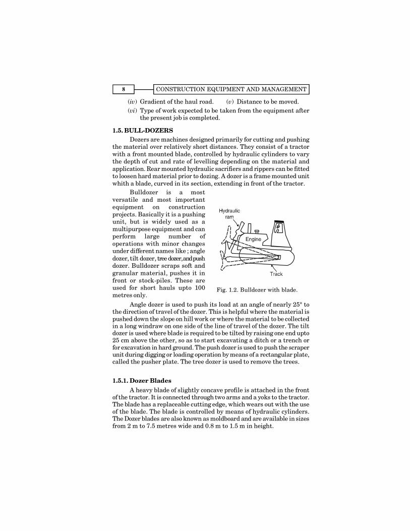
the material over relatively short distances. They consist of a tractorwith a front mounted blade, controlled by hydraulic cylinders to varythe depth of cut and rate of levelling depending on the material andapplication. Rear mounted hydraulic sacrifiers and rippers can be fittedto loosen hard material prior to dozing. A dozer is a frame mounted unitwhith a blade, curved in its section, extending in front of the tractor.
Bulldozer is a mostversatile and most importantequipment on constructionprojects. Basically it is a pushingunit, but is widely used as amultipurpose equipment and canperform large number ofoperations with minor changesunder different names like ; angledozer, tilt dozer, tree dozer, and pushdozer. Bulldozer scraps soft andgranular material, pushes it infront or stock-piles. These areused for short hauls upto 100metres only.
Angle dozer is used to push its load at an angle of nearly 25° tothe direction of travel of the dozer. This is helpful where the material ispushed down the slope on hill work or where the material to be collectedin a long windraw on one side of the line of travel of the dozer. The tiltdozer is used where blade is required to be tilted by raising one end upto25 cm above the other, so as to start excavating a ditch or a trench orfor excavation in hard ground. The push dozer is used to push the scraperunit during digging or loading operation by means of a rectangular plate,called the pusher plate. The tree dozer is used to remove the trees.
1.5.1. Dozer BladesA heavy blade of slightly concave profile is attached in the front
of the tractor. It is connected through two arms and a yoks to the tractor.The blade has a replaceable cutting edge, which wears out with the useof the blade. The blade is controlled by means of hydraulic cylinders.The Dozer blades are also known as moldboard and are available in sizesfrom 2 m to 7.5 metres wide and 0.8 m to 1.5 m in height.
Fig. 1.2. Bulldozer with blade.

HEAVY EARTH MOVING EQUIPMENT 9
Dozer blades vary in sizes and design based on spcific workapplications. The hardened cutting edges and side bits are bolted, as itenables easy replacement when worn out.
Dozer blades can have three types of movements, namely; tilt,pitch, and angling. All these three features are not available to all blades,but any two of these may be incorporated in a single mount.
(1) Tilt. In this case Dozer can raise or lower the either end of theblade in the vertical plane. Tilting permits concentration ofdozer driving power on a limited portion of the blade�s length.
(2) Pitch. In this case the top of the blade can be pitched forwardor backward varying the angle of attack of the cutting edge.This is a pivotal movement about the point of connectionbetween the dozer and blade. When the top of the blade ispitched forward, the bottom edge moves back which increasesthe angle of cutting edge attack.
(3) Angling. In this case blades mounted on a C-frame can beturned from the direction of travel. In angling the blade isturned so that it is not perpendicular to the direction of travelof the dozer. This results in pushing the material to roll offthe trailing end of the blade.
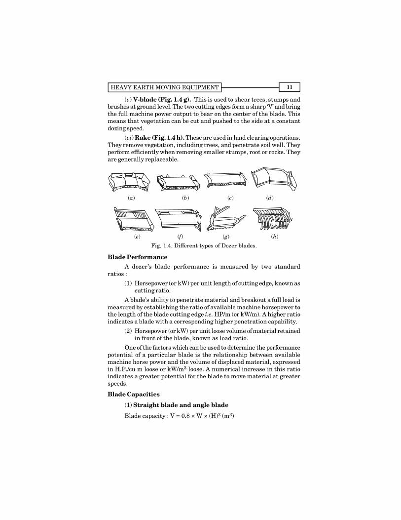
Types of Blades1. Blades for Production Dozing
(i) Universal U-Blade (Fig. 1.4.a). U-Blade should be selectedfor moving large amount of materials over long distances, and isappropriate for moving easily dozed material. These blades are used forstockpile work, trapping for loaders, and land reclamation. (Ref. Fig. 1.6)
(ii) Straight or S-Blade (Fig. 1.4.b). Being smaller than the U-blade, it is easier to manoeuvre. This blade penetrates material easily.Addition of a tilt cylinder increases the versatility of this blade. It canmove heavy materials more efficiently. These have no curvature in theirlength, and are mounted in a fixed position, perpendicular to the line oftravel. (Ref. Fig. 1.5)
2. Blades for Special Applications
Some of the more familiar special applications of dozing bladesare described below :
(i) Angle Blade (Fig. 1.4.c). The angle blade can be mountedstraight or angled 25° to either side. It is designed to move materialtowards the sides of a cut, as required in road construction, backfillingor cutting ditches, and substantially reduces the amount of manoeuvring.
(ii)Special application U-blades (Fig. 1.4 d). These blades
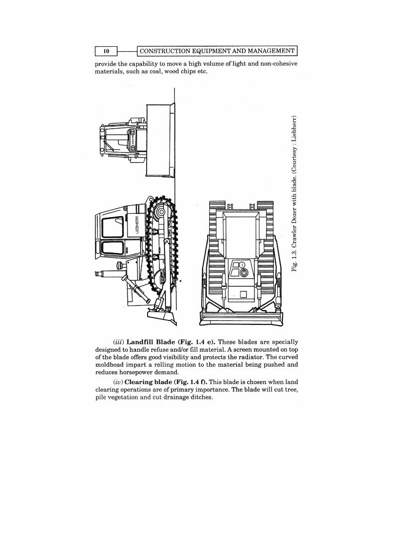
HEAVY EARTH MOVING EQUIPMENT 11
(v) V-blade (Fig. 1.4 g). This is used to shear trees, stumps andbrushes at ground level. The two cutting edges form a sharp �V� and bringthe full machine power output to bear on the center of the blade. Thismeans that vegetation can be cut and pushed to the side at a constantdozing speed.
(vi) Rake (Fig. 1.4 h). These are used in land clearing operations.They remove vegetation, including trees, and penetrate soil well. Theyperform efficiently when removing smaller stumps, root or rocks. Theyare generally replaceable.
(a) (b) (c) (d)
(e) (f) (g) (h)
Fig. 1.4. Different types of Dozer blades.
Blade PerformanceA dozer�s blade performance is measured by two standard
ratios :
(1) Horsepower (or kW) per unit length of cutting edge, known ascutting ratio.
A blade�s ability to penetrate material and breakout a full load ismeasured by establishing the ratio of available machine horsepower tothe length of the blade cutting edge i.e. HP/m (or kW/m). A higher ratioindicates a blade with a corresponding higher penetration capability.
(2) Horsepower (or kW) per unit loose volume of material retainedin front of the blade, known as load ratio.
One of the factors which can be used to determine the performancepotential of a particular blade is the relationship between availablemachine horse power and the volume of displaced material, expressedin H.P./cu m loose or kW/m3 loose. A numerical increase in this ratioindicates a greater potential for the blade to move material at greaterspeeds.
Blade Capacities
(1) Straight blade and angle blade
Blade capacity : V = 0.8 × W × (H)2 (m3)
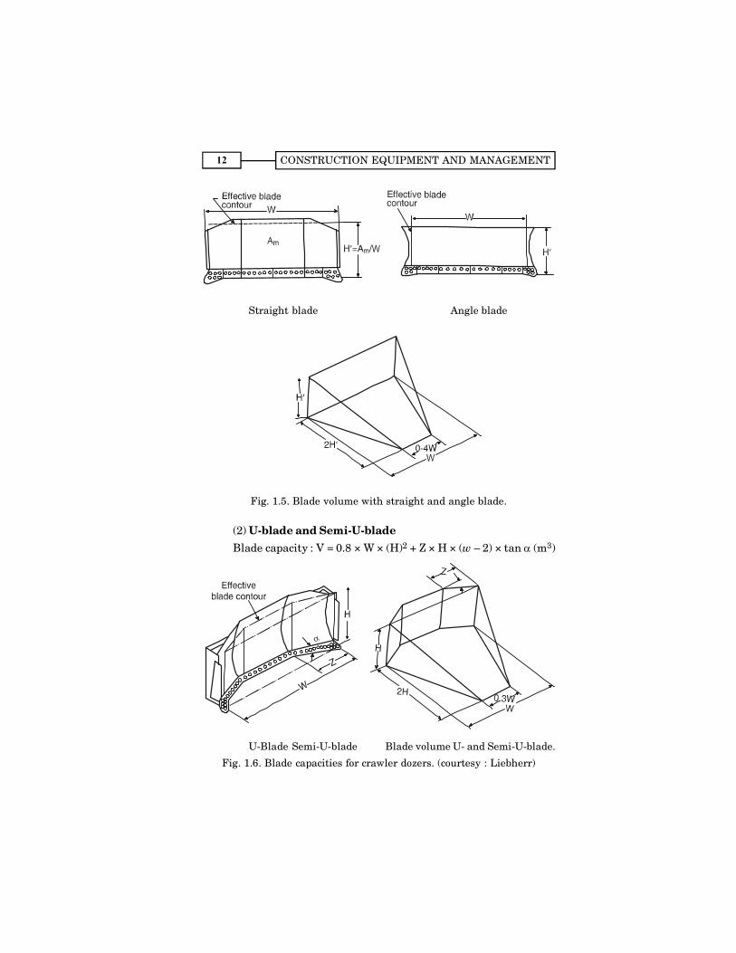
CONSTRUCTION EQUIPMENT AND MANAGEMENT12
Straight blade Angle blade
Fig. 1.5. Blade volume with straight and angle blade.
(2) U-blade and Semi-U-bladeBlade capacity : V = 0.8 × W × (H)2 + Z × H × (w � 2) × tan α (m3)
U-Blade Semi-U-blade Blade volume U- and Semi-U-blade.
Fig. 1.6. Blade capacities for crawler dozers. (courtesy : Liebherr)
HEAVY EARTH MOVING EQUIPMENT 13
Material Evaluation
All other factors being equal, dozing performance will still varyconsiderably, depending on the nature of the material to be displaced.Moisture content, particle size and number of voids are the moreimportant characteristics influencing dozing performances.
(a) Moisture Content. If moisture falls below the optimummoisture content value, particles will adhere to each other more andmore and, in effect, it make it difficult to break material out of its naturalstate. If the moisture content increases above the optimum, materialbecomes heavy and will thus have a negative effect on dozingperformance.
(b) Particle Size. The size of the individual particles making upa specific type of material has a direct bearing on the ability of a dozerblade to penetrate and loosen material. Large particles resist penetrationmore than smaller ones, requiring more dozing power. Additionally,sharp-edged particles exert more force against the curl movement of theblade. Therefore, material consisting of irregularly and sharp-edgedparticles is more difficult to doze than material composed of round-edgedparticles.
(c) Voids. Relatively dense materials with few voids contain largenumbers of individual particles in close contact with each other. Becauseof this, more force is required to break up this tightly bonded material.Also such material is generally heavy, making additional demands onthe available horse power of the dozer.
1.5.2. RippersCrawler-tractor, mounted with ripper is finding increasing use in
construction, mining and quarrying. Cost of ripping vary from materialto material to be ripped and some times very hard rock formations cannotbe ripped. Cost of ripping should be compared with the cost of �drilling�blasting� to consider economical way of excavation. While consideringripping cost, life of ripping tips as well as shortening of life ofundercarriage should be considered.
Characteristics of the material to be ripped influence the selectionof ripper type ; number of shanks required, ripping speed and amountof ripper penetration. For hard material single shank is preferred, butwhere material is easily penetrated and fractured into small pieces, atwo or three shank ripper is used.
Ripper TypesVarious types of rippers are used with the dozers. These may be
towed units, integrated units, backrippers. Towed units are generally
CONSTRUCTION EQUIPMENT AND MANAGEMENT14
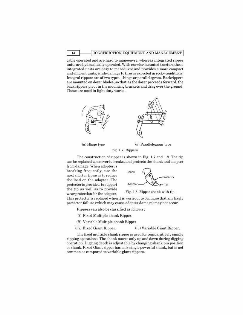
cable operated and are hard to manoeuvre, whereas integrated ripperunits are hydrualically operated. With crawler mounted tractors theseintegrated units are easy to manoeuvre and provides a more compactand efficient units, while damage to tires is expected in rocky conditions.Integral rippers are of two types�hinge or parallelogram. Backrippersare mounted on dozer blades, so that as the dozer proceeds forward, theback rippers pivot in the mounting brackets and drag over the ground.Those are used in light duty works.
(a) Hinge type (b) Parallelogram type
Fig. 1.7. Rippers.
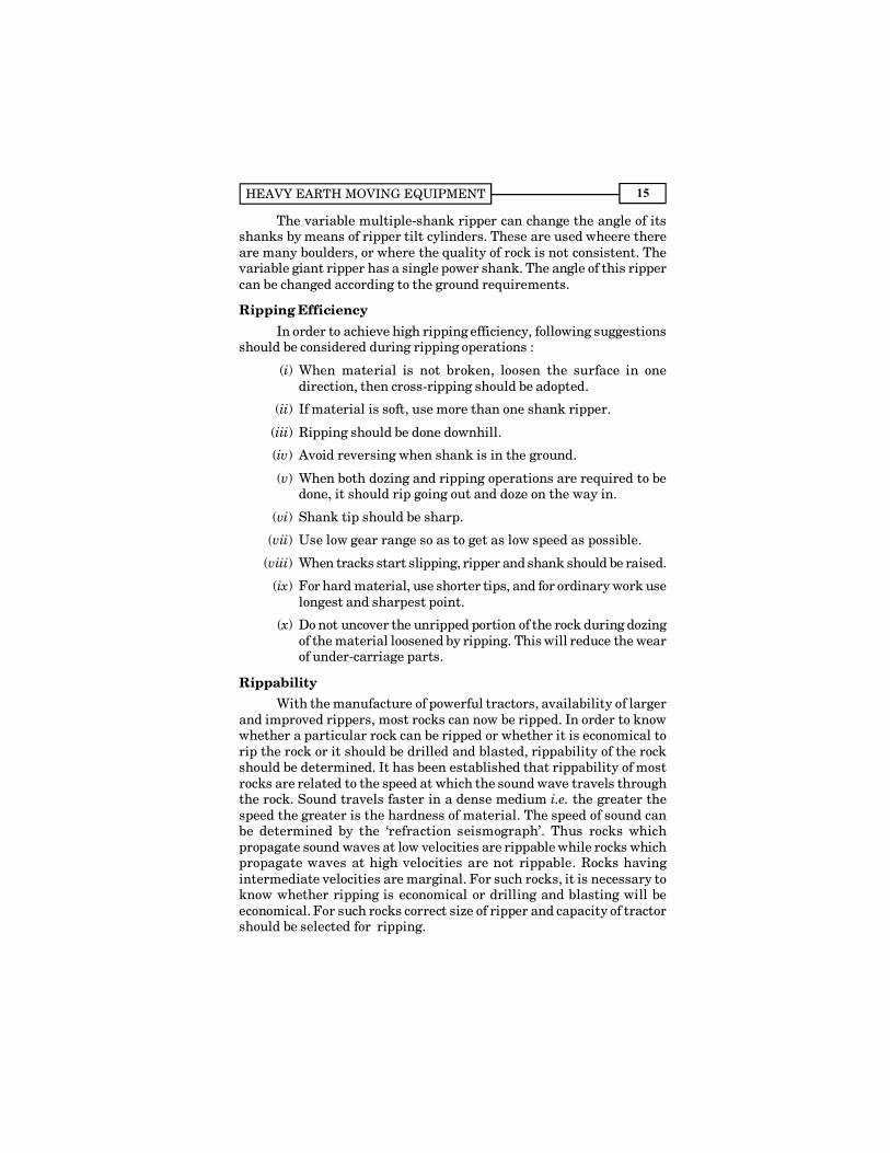
The construction of ripper is shown in Fig. 1.7 and 1.8. The tipcan be replaced whenever it breaks, and protects the shank and adopterfrom damage. When adopter isbreaking frequently, use thenext shorter tip so as to reducethe load on the adopter. Theprotector is provided to supportthe tip as well as to providewear protection for the adopter.This protector is replaced when it is worn out to 6 mm, so that any likelyprotector failure (which may cause adopter damage) may not occur.
Rippers can also be classified as follows :
(i) Fixed Multiple-shank Ripper.
(ii) Variable Multiple-shank Ripper.
(iii) Fixed Giant Ripper. (iv) Variable Giant Ripper.
The fixed multiple shank ripper is used for comparatively simpleripping operations. The shank moves only up and down during diggingoperation. Digging depth is adjustable by changing shank pin positionor shank. Fixed Giant ripper has only single powerful shank, but is notcommon as compared to variable giant rippers.
Fig. 1.8. Ripper shank with tip.
HEAVY EARTH MOVING EQUIPMENT 15
The variable multiple-shank ripper can change the angle of itsshanks by means of ripper tilt cylinders. These are used wheere thereare many boulders, or where the quality of rock is not consistent. Thevariable giant ripper has a single power shank. The angle of this rippercan be changed according to the ground requirements.
Ripping EfficiencyIn order to achieve high ripping efficiency, following suggestions
should be considered during ripping operations :
(i) When material is not broken, loosen the surface in onedirection, then cross-ripping should be adopted.
(ii) If material is soft, use more than one shank ripper.
(iii) Ripping should be done downhill.
(iv) Avoid reversing when shank is in the ground.
(v) When both dozing and ripping operations are required to bedone, it should rip going out and doze on the way in.
(vi) Shank tip should be sharp.
(vii) Use low gear range so as to get as low speed as possible.
(viii) When tracks start slipping, ripper and shank should be raised.
(ix) For hard material, use shorter tips, and for ordinary work uselongest and sharpest point.
(x) Do not uncover the unripped portion of the rock during dozingof the material loosened by ripping. This will reduce the wearof under-carriage parts.
RippabilityWith the manufacture of powerful tractors, availability of larger
and improved rippers, most rocks can now be ripped. In order to knowwhether a particular rock can be ripped or whether it is economical torip the rock or it should be drilled and blasted, rippability of the rockshould be determined. It has been established that rippability of mostrocks are related to the speed at which the sound wave travels throughthe rock. Sound travels faster in a dense medium i.e. the greater thespeed the greater is the hardness of material. The speed of sound canbe determined by the �refraction seismograph�. Thus rocks whichpropagate sound waves at low velocities are rippable while rocks whichpropagate waves at high velocities are not rippable. Rocks havingintermediate velocities are marginal. For such rocks, it is necessary toknow whether ripping is economical or drilling and blasting will beeconomical. For such rocks correct size of ripper and capacity of tractorshould be selected for ripping.
CONSTRUCTION EQUIPMENT AND MANAGEMENT16
Cost of earth excavation, without rock is very less as compared toexcavating a rock by ripping. When ripping a rock, life of undercarriagecomponents will be shortened due to fast wear and shocks etc.hence ripping tips wear out at a faster rate. This also reduces thelife of the tractor. These factors need be considered while determiningthe ripping cost. This cost should be compared with excavation of rockusing �drilling and blasting� technique to determine an economicalmethod.
Effectiveness of a ripper depends on :
(a) Down pressure at the ripper tip.
(b) The tractor usable to advance the tip; a function of poweravailable, tractor weight and coefficient of traction.
(c) Properties of the material being ripped, faulted, weathered andcrystalline structure.
The number of shanks used depends on the size of the dozer, thedepth of penetration desired, the resistance of the material being ripped,and the degree of breakage of the material desired.
Physical Characteristics that favour ripping are :
(i) Fractures, faults and joints indicate weak rock and facilitateripping.
(ii) Weathering makes the rock to be easily ripped. As greater thedegree of weatheing the more easily the rock is ripped.
(iii) Brittleness and crystalline structure.
(iv) High degree of stratification offers good possibilities forripping.
(v) Large grain size and coarse-grained rocks rip more easily thanfine-grained rocks.
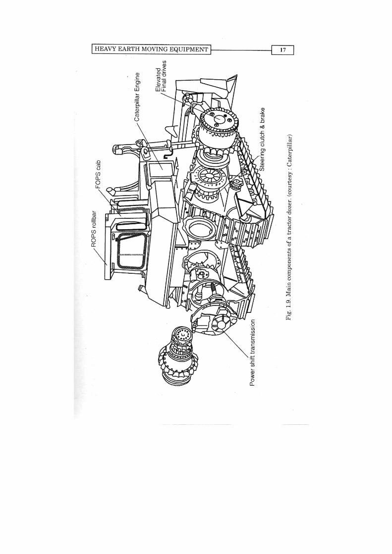
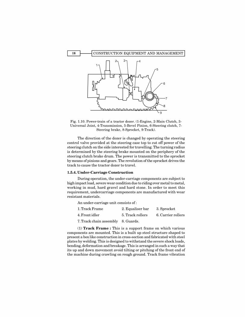
1.5.3. Power Train of a Dozer
In a tractor Dozer the driving power from the diesel engine istransmitted to the main clutch through the flywheel. Power from themain clutch shaft is transmitted through the universal joint to the mainshaft of the transmission. Power obtained through a gear selectedaccording to the load is transmited from the transmission to the bevelpinion at the rear end of the transmission case. This power is directedinto the right and left directions by the bevel pinion and the bevel gear.Steering clutches which are provided at both the ends of the bevel gearshaft intercept and control the direction of power from the bevel gearshaft to the final drive.
CONSTRUCTION EQUIPMENT AND MANAGEMENT18
Fig. 1.10. Power-train of a tractor dozer. (1-Engine, 2-Main Clutch, 3-Universal Joint, 4-Transmission, 5-Bevel Pinion, 6-Steering clutch, 7-
Steering brake, 8-Sprocket, 9-Track).
The direction of the dozer is changed by operating the steeringcontrol valve provided at the steering case top to cut off power of thesteering clutch on the side interested for travelling. The turning radiusis determined by the steering brake mounted on the periphery of thesteering clutch brake drum. The power is transmitted to the sprocketby means of pinions and gears. The revolution of the sprocket drives thetrack to cause the tractor dozer to travel.
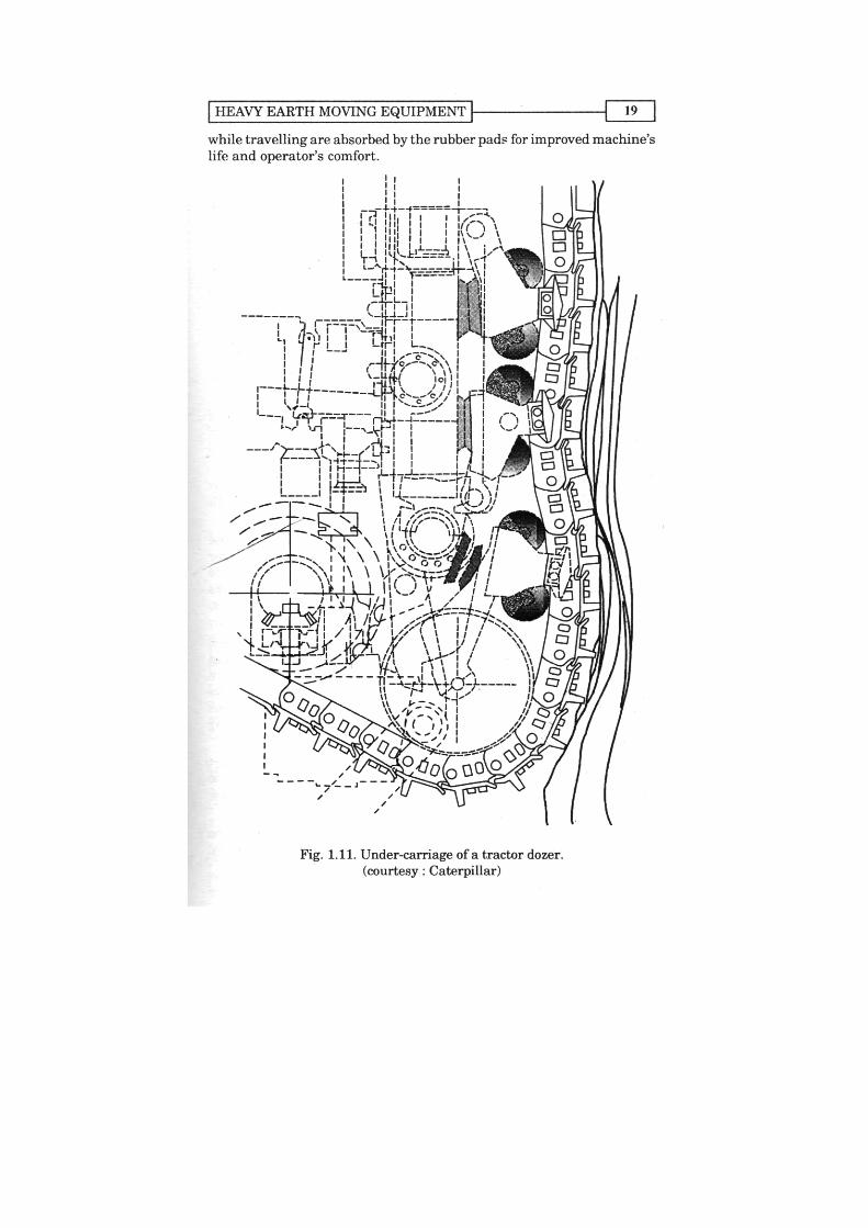
1.5.4. Under-Carriage Construction
During operation, the under-carriage components are subject tohigh impact load, severe wear condition due to riding over metal to metal,working in mud, hard gravel and hard stone. In order to meet thisrequirement, undercarriage components are manufactured with wearresistant materials.
An under-carriage unit consists of :
1.Track Frame 2. Equaliser bar 3. Sprocket
4.Front idler 5. Track rollers 6. Carrier rollers
7.Track chain assembly 8. Guards.
(1) Track Frame : This is a support frame on which variouscomponents are mounted. This is a built up steel structure shaped topresent a box like construction in cross-section and fabricated with steelplates by welding. This is designed to withstand the severe shock loads,bending, deformation and breakage. This is arranged in such a way thatits up and down movement avoid tilting or pitching of the front end ofthe machine during crawling on rough ground. Track frame vibration
CONSTRUCTION EQUIPMENT AND MANAGEMENT20
(2) Equaliser Bar : This is a welded box like beam of steel plateswhich distributes the weight of front portion of the machine equally tothe two track frames. Its centre point is pivoted to the cross bar of thechassis.
(3) Sprocket. Sprocket revolves in a loop of endless track chainto transmit driving power to the track to roll.
(4) Front Idler. This supports the front end part of the track chainto allow the track to roll straight over rough ground. The idler slides aswell as can move upward and downward at the front end of the frameby the guide plates attached to the underside of the bearing andconnected to the recoil spring assembly through yock to maintain tracktension tight enough to keep suficient engagement of the sprocket wheelwith track.
(5) Track Rollers : These are arranged under each track frameand bolted on to it. They evenly distribute the weight of the machine onthe track and ride on the tread surface of track link.
(6) Carrier Rollers : These are installed on to the upper side ofthe track frame over a support. It guides and support the upper half ofthe track loop to proper rolling condition and avoids dangling due to itsweight.
(7) Track Chain Assembly : Track chain assembly is formed byjoining links, pins, bushings and mounting track shoes on the links withthe help of bolts and nuts.
(a) Track link assembly : The links support the weight of themachine and are subjected to frequent impact load due to riding overrocks. These are made by forging of alloy steel (manganese steel) andsurface hardened to provide wear and shock resistance property. Linksact as rail along direction of machines travel. A pair of links fix shoes,pins and bushings, seals and spacers.
Pins and bushes both are press fitted in their respective holesprovided in the links. Sections of the track are joined by passing the pinof one section through the bush of the next section. Outer surface of abushing wears out as it comes in contact with sprocket teeth where asinner suface wears out as it is rotationally supported by the pinsinvolved. The bushing act as the medium of transmission of drivingpower from sprocket wheel to the track.
(b) Track shoe : A track sho is composed of a plate which supporta part of the machine weight and grousers which permits the shoe togrip the ground and penetrate soil to its full depth for a good tractionand protection against side slippage under most conditions.
Track shoes are subjected to impact load, large stress and abrationdue to sliding contact with ground. These are cast or forged of specialalloy steel and heat treated. The shoes are bolted to the links.

HEAVY EARTH MOVING EQUIPMENT 21
Narrow shoes with heavy, rugged grousers and plate sections arerecommended for rock jobs. Wider track shows are suitable for softunderfooting to acquire maximum floatation and maximum drawbarpull.
(8) Track roller guards : These protects track rollers from beingdamaged by rocks and debris, these also prevents track from slipping.How to Achieve Long Life of Under-Carriage
Following are the few tips which help in getting long life ofunder carriage.
(1) Avoid unnecessary high speed operation.(2) Avoid sharp and pivot turn.
(3) Avoid reverse direction travelling.(4) Avoid loading only on one side for long period of time.(5) Avoid track shoe slip under undue load.(6) Avoid riding over big boulders.
(7) Avoid leaving a machine stopped on slant.(8) Avoid turning machine only in one direction.(9) Follow maintenance schedule as recommended by
manufacturer
Undercarriage MaintenanceSince undercarriage parts are very costly (about 40% of the cost
of equipment) and these are subjected to severe applications, regularchecking and maintenance is most necessary to get the bestpeerformance. Even in the best maintained equipment, the replacementcost of undercarriage parts is almost 100% of the capital cost of theequipment during its economical life. This is very high as compared tothe 50% for all other components put together. This itself justifies theimportance of regular inspection and maintenance of undercarriageparts and its proper operation. Bad operation too causes premature wearand failures, spinning causes fast wear and reduced life, more severeapplications, like ripping specially on hard strata considering itscapacity, also shortens the under-carriage life.
During spinning, tracks drag over the abrasive material and shoesteel is ground away unnecessarily. Inspite of lot of improvement in trackconstruction, dirt is still the main enemy of the tracks and rollers. Thewear is proportional to the degree of abrasiveness of the material to bemoved and load of the components.
For better tracklife, always provide right quality bolts and nutspurchased from the right source. Loose, broken or low quality bolts andnuts cause abnormal wear on track shoes and assemblies and affectsthe life of undercarriage.
CONSTRUCTION EQUIPMENT AND MANAGEMENT22
Proper track tension plays an important role in the service life ofthe undercarriage. Too tight track increases the load and cause fastertrack component wear, while too loose track causes links to beat againstthe top carrier rollers, damaging it. As a thumb rule 25 mm of slack (notsag) gives correct tension on undercarriage of most equipment. Theexpception is equipment fitted with only one carrier roller per side, where20 mm slack produces best results. This slack should be checked underthe actual working conditions.
Experiments have shown that, in order to extend track joint life,pins and bushes should be turned before the link wear reaches thehalfway point to total destruction due to wear. This is done to bringunused wear surfaces into play, and by turning there is less chance ofmetal fatigue, cracking, bending or breaking.
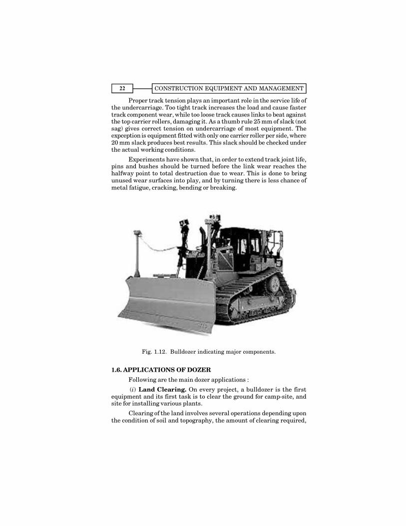
Fig. 1.12. Bulldozer indicating major components.
1.6. APPLICATIONS OF DOZERFollowing are the main dozer applications :
(i) Land Clearing. On every project, a bulldozer is the firstequipment and its first task is to clear the ground for camp-site, andsite for installing various plants.
Clearing of the land involves several operations depending uponthe condition of soil and topography, the amount of clearing required,
HEAVY EARTH MOVING EQUIPMENT 23
type of vegetation and the purpose for which clearing is done. Theoperations may include, removal of soil to remove unevennesss of theground, removal of trees and stumps including roots, removal ofvegetation etc.For this purpose various types of equipment can be used.These may be tractor mounted bulldozers, tractor mounted specialblades in which the stringer penetrates the ground to cut the mainhorizontal roots of the tree or a blade which slides along the surface ofthe ground for cutting vegetation, tractor mounted rakes to be used tograb and pile trees, boulders etc. without transporting excess amountof soil, tractor mounted clamp rakes to pick up felled trees and transportthem to a place of dumping.
(ii) Stripping. It is the removal of top soil that is not usable.Stripping is planned in such a way so that haulage is for minimumdistance. Upto the distance of 100 meters dozer itself is used, but formore distances scrapers should be employed.
(iii) Sidehill cuts. Sidehill cuts should always be started from thetop and then worked downward.
(iv) Backfilling. In backfilling material is pushed ahead of thedozer over embankments into ditches or against a structure. Angledozers are found more suitable for this job as they can drift materialinto the trench while maintaining forward motion.
(v) Ditching. The rough ditches can be prepared by the dozers.These are constructed with a straight blade by working at right anglesto the length of the ditch.
(vi) Spreading. These are also used for spreading the materialhauled by trucks, scrapers etc. Depth of spread is adjusted consideringthe thickness required.
(vii) Dozing rocks and frozen ground. Rocks are generallyremoved by using one corner of the blade, as the full power is thus appliedon this section of the blade. Large sections of rocks are removed by usingthe blade to lift the rock, simultaneously applying power to the tracks.
(viii) Maintaining haul roads.(ix) Clearing the floors of borrow and quarry pits.(x) Digging. A dozer while moving forward with the blade
inserted in the soil digs it. If the blade is lowered further, more workcan be done, thereby resistance will increase, as a thick slice requiresmore digging power than a thin one. The blade, during operation, shouldbe lowered or raised gradually to avoid bumps in the path.
(xi) Breaking Pile. A pile may be knocked down by walking intoit with the blade at the desired grade, after which it may be spread orpiled elsewhere. If the heap is too large, it may be cut away in parts,either directly, or if it is not possible, the side cut should be repeatedfrom different angles.
CONSTRUCTION EQUIPMENT AND MANAGEMENT24
1.7. OUTPUT OF BULL DOZERSThe production of bull dozers mainly depend upon the following
factors :(i) Size and condition of the bulldozer
(ii) Distance travelled by the bulldozer(iii) Speed of operaton(iv) Characteristics of soil being handled(v) Surface on which bulldozer is operating
(vi) Efficiency.When dozing the materials that tend to stick together and remain
in front of the blade during dozing, the efficiency is higher as comparedto that when dozing loose granular earth or shattered rock. Whereashard and cemented material needs extra efforts in preblasting or ripping.
Output of a dozer in bank-volume/hr.
= Loose volume handled/trip × S × 60t × efficiency
where, S = Swell factor,and t = Cycle time (time required/trip) in minutes.
Swell Factor. As we know that, loosening of earth causes anincrease in volume, which if expressed as a % of original undisturbedvolume gives the percentage of swell earth. The ratio of volume of originalearth to the loose earth is known as swell factor.
Loose volume handled/trip = Production per cycle= Blade width × (Blade height)2 × Blade factor.
Blade factor depends upon the type of soil and generally takenbetween 0.4 to 1.1. depending upon difficulty to easy dozing work.
Cycle time (in minutes) = + +D D GF Rwhere, D = Haul distance (metres)
F = Forward speed (m/min)R = Reverse speed (m/min)G = Gear shifting and manoeuvre time (minutes)
Volume ConversionThe volume measure varies with the state of the soil. States of
soil encountered in earthmoving operations are : (a) in-place natural soil(known as bank soil); (b) loose excavated bulk soil, and (c) compactedsoil. The bank volume swells when heaped in a loose state afterexcavation, and shrinks when compacted.
Volume conversion of common natural soils into three states isgiven hereunder :
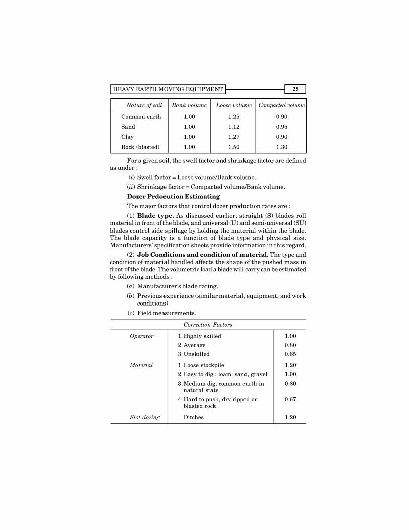
HEAVY EARTH MOVING EQUIPMENT 25
Nature of soil Bank volume Loose volume Compacted volume
Common earth 1.00 1.25 0.90
Sand 1.00 1.12 0.95
Clay 1.00 1.27 0.90
Rock (blasted) 1.00 1.50 1.30
For a given soil, the swell factor and shrinkage factor are definedas under :
(i) Swell factor = Loose volume/Bank volume.
(ii) Shrinkage factor = Compacted volume/Bank volume.
Dozer Prdocution EstimatingThe major factors that control dozer production rates are :
(1) Blade type. As discussed earlier, straight (S) blades rollmaterial in front of the blade, and universal (U) and semi-universal (SU)blades control side spillage by holding the material within the blade.The blade capacity is a function of blade type and physical size.Manufacturers� specification sheets provide information in this regard.
(2) Job Conditions and condition of material. The type andcondition of material handled affects the shape of the pushed mass infront of the blade. The volumetric load a blade will carry can be estimatedby following methods :
(a) Manufacturer�s blade rating.
(b) Previous experience (similar material, equipment, and workconditions).
(c) Field measurements.
Correction Factors
Operator 1. Highly skilled 1.00
2. Average 0.80
3. Unskilled 0.65
Material 1. Loose stockpile 1.20
2. Easy to dig : loam, sand, gravel 1.00
3. Medium dig, common earth in 0.80natural state
4. Hard to push, dry ripped or 0.67blasted rock
Slot dozing Ditches 1.20
CONSTRUCTION EQUIPMENT AND MANAGEMENT26
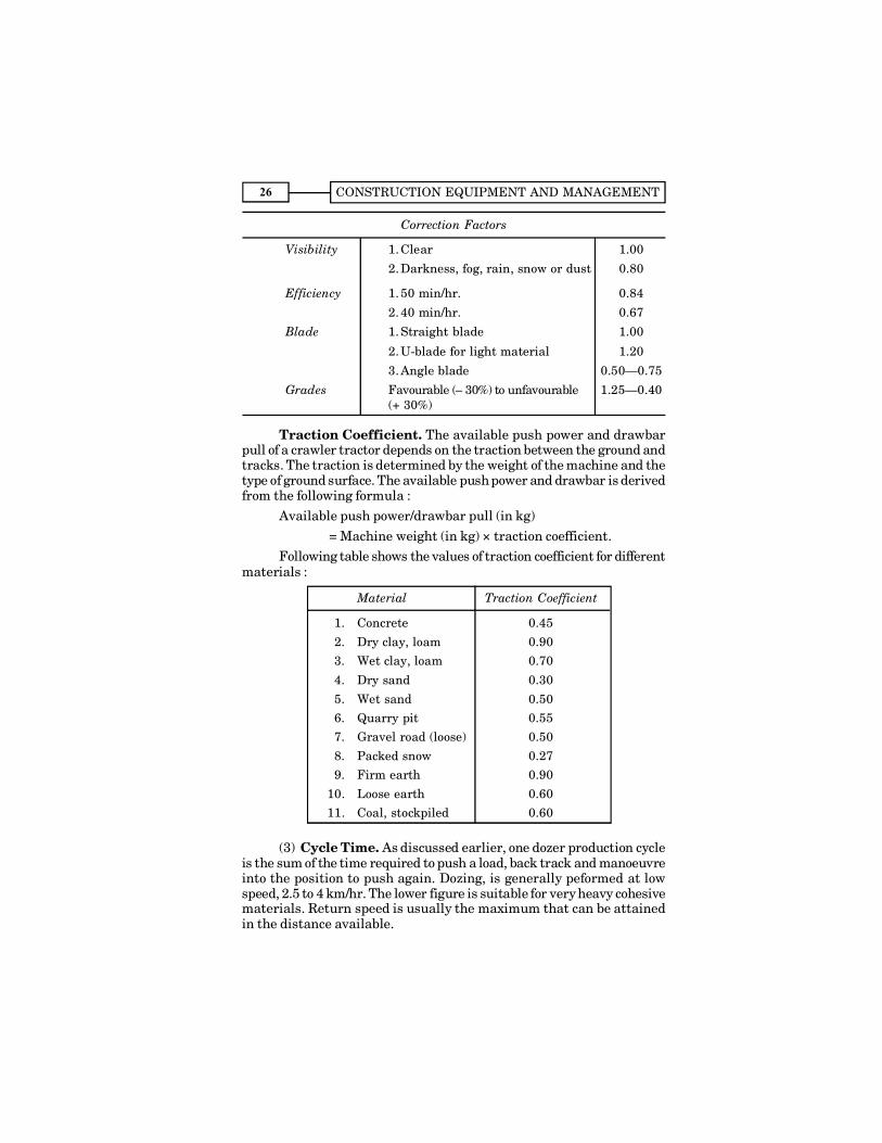
Correction Factors
Visibility 1. Clear 1.00
2. Darkness, fog, rain, snow or dust 0.80
Efficiency 1. 50 min/hr. 0.84
2. 40 min/hr. 0.67
Blade 1. Straight blade 1.00
2. U-blade for light material 1.20
3. Angle blade 0.50�0.75
Grades Favourable (� 30%) to unfavourable 1.25�0.40(+ 30%)
Traction Coefficient. The available push power and drawbarpull of a crawler tractor depends on the traction between the ground andtracks. The traction is determined by the weight of the machine and thetype of ground surface. The available push power and drawbar is derivedfrom the following formula :
Available push power/drawbar pull (in kg)= Machine weight (in kg) × traction coefficient.
Following table shows the values of traction coefficient for differentmaterials :
Material Traction Coefficient
1. Concrete 0.45
2. Dry clay, loam 0.903. Wet clay, loam 0.70
4. Dry sand 0.30
5. Wet sand 0.506. Quarry pit 0.557. Gravel road (loose) 0.50
8. Packed snow 0.279. Firm earth 0.90
10. Loose earth 0.6011. Coal, stockpiled 0.60
(3) Cycle Time. As discussed earlier, one dozer production cycleis the sum of the time required to push a load, back track and manoeuvreinto the position to push again. Dozing, is generally peformed at lowspeed, 2.5 to 4 km/hr. The lower figure is suitable for very heavy cohesivematerials. Return speed is usually the maximum that can be attainedin the distance available.
HEAVY EARTH MOVING EQUIPMENT 27
1.7.1. Output of RippersOutput of rippers depend upon the characateristics of soil, size of
the tractor dozer, speed of the machine, shape and size of the ripper tooth,number of shanks used, and depth and width of ripping pass. However,following are the formulae used in general for calculating the output ofripper :
Production per hour= (Bank-volume ripped per pass) × (Number of passes per hour)
where, Bank-volume ripped per pass= Length of pass × Width of ripping pass × Depth of penetration
× EfficiencyNumber of passes per hour
= ( )60
Time for making one pass in min
and time taken in one pass = Len gth of pa ss + Turn round t im eTra velling speed
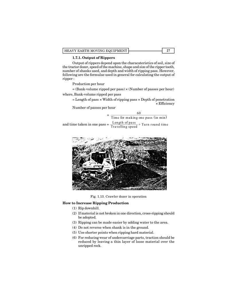
Fig. 1.13. Crawler dozer in operation
How to Increase Ripping Production(1) Rip downhill.(2) If material is not broken in one direction, cross-ripping should
be adopted.(3) Ripping can be made easier by adding water to the area.(4) Do not reverse when shank is in the ground.(5) Use shorter points when ripping hard material.(6) For reducing wear of undercarriage parts, traction should be
reduced by leaving a thin layer of loose material over theunripped rock.

CONSTRUCTION EQUIPMENT AND MANAGEMENT28
(7) As soon as tracks starts slipping, ripper and shanks shouldbe raised.
(8) Use low gear while ripping a rock.The biggest bulldozer : The biggest bulldozer manufactured so
far, is fitted with the turbocharged engine capable to produce 574 kwpower and has a weight of nearly 93 tons. The blades are capable ofhandling upto 32 m3. The single ripper having 4 operating positions,adjustable for a maximum digging depthof 1.8 m with a force of 26 tonsis available.1.8. SCRAPERS
Scrapers are the devices to scrap the ground and load itsimultaneously, transport it over the required distance, dump and thenspread the dumped material over the required area in required thicknesslevel, and return to the pit for the next cycle. Thus the scrapers aredesigned to dig, load, haul, dump and spread and some times called ascarry all.
The scrapers are of three types : (a) towed type, (b) self propelledor motorised or conventional type, (c) self loading or elevating scraper.
Scrapers can also be classified as (1) Crawler tractor scrapers orWheel tired tractor scrapers, (2) Pusher loaded or self loaded scrapers.
The towed scrapers are provided with either cable or hydrauliccontrol. Although these are becoming obsolete but even then somecontractors use them because when coupled to a suitably poweredcrawler tractor, they can operate in extremely adverse conditions.
Self-propelled or motorised or conventional scrapers are mostpopular now-a-days. These are generally manufactured in ranges from10 to 25 cubic metres. A motorised scraper needs push loading by acrawler mounted or a wheeled tractor. Wheeled scrapers have morehauling speed and hence are suitable for long distance hauling whilecrawler-towed scrapers travel at slower speed and can be used for shorthauls only.
Fig. 1.14. Self propelled scraper.
The problem of loading by a pusher is overcome by the third typeof scraper known as self-loading or elevating scrapers. These are twin
HEAVY EARTH MOVING EQUIPMENT 29
engine scrapers and can work completely independently of all otherplants. It does not need a pusher. To make them more effective andcompetitive with dump trucks, some of the manufacturers are producingthree axle-scrapers of 40 cubic meter pay loads. However, these havecertain limitations, firstly, the elevator cannot load particularly freeflowing sands or handle rock infested soils. Secondly pay loads arerestricted because of the additional weight of the loading elevator andits drive system. Thirdly, increase in loading time, the inability to obtaina full load, indicates that for powerful units a pusher is still required.
ConstructionA self-propelled or motorised type scraper has following main
parts :
(( i) Bowl. The bowl is a pan to hold the scraped dirt. It is hingedat the rear corners to the rear axle inside the wheels, and is capable oftilting down for digging or ejecting. The bowl size is specified to indicatethe size of the scraper.
(ii) Cutting edge. The bowl has a cutting edge attached at thebottom.The cutting edge is lowered into the dirt to make a shallow cut.
(iii) Apron. This is a wall in front of the bowl, which opens andcloses to regulate the flow of the earth in and out of the bowl. This canopen or closes in carrying position as well.
(iv) Tail gate or ejector. These are the rear of the pan which iscapable of forward and backward movement inside the bowl. Duringloading it remains at its rear wall, while moves forward to help in ejectingthe load during dumping.
All these items are controlled by the hydraulic system. Movementsof these parts are controlled hydraulically. In hydraulic system, oilpressure works in the double acting rams provided separately for bowl,apron, and tail gate. The flow of oil in these rams is controlled by valves.
Specification of a ScraperUsually the capacity of a scarper is given in terms of cubic metres
struck and cubic metres heaped. Struck capacity of a scraper is the actualvolume enclosed by the bowl and apron, struck off by a straight linepassed along the top edge of the side plates. In other words it is thevolume of the material levelled with the top edges of the bowl. Heapedcapacity is the sum of the struck capacity and the volume enclosed bythe four plates at a 1 : 1 slope extending upward.
The other important specifications of the scraper are type ofexcavator i.e. towed type or self-propelled or self-loaded ; two or threeaxle scraper, number of engines i.e. one or two engines ; horsepower ofthe engine at the flywheel ; pusher required with the scraper ; track-type or wheel type ; pay load capacity ; size of the tyres etc.
CONSTRUCTION EQUIPMENT AND MANAGEMENT30
OperationOperation of a scraper is described hereunder for an earth work
application :(i) Loading or digging. Operator moves to the cut with the
ejector at the rear and the apron raised approximately to 40 cm. Thebowl is then lowered to the desired depth of cut, increase engine speed,move forward in first gear keeping optimum depth of cut. When the bowlis full, the apron is closed and the bowl is then raised.
(ii) Transporting. The bowl is transported in high gear in raisedposition to provide sufficient clearance. During transporting, apronshould be fully closed to prevent loss of the material, and the ejectorshould remain in the rear position.
(iii)Unloading. Unloading in a scraper is also termed as �dumpingand spreading�. The bowl should be positioned to spread the material tothe desired depth during this operation. A partial opening of the apronduring the initial unloading will help in even spreading. For wet andsticky material, the apron should be raised and lowered repeatedly untilthe material behind it is loosened and drops out of the bowl. Then theejector is moved forward to push the remaining material out of the bowlat a uniform rate.
When the dump is complete, the tail gate is fully retracted, theapron dropped and the �bowl� raised to transporting position. Thefinishing touch during spreading is done by grading it with the cuttingedge, and the unit then hurries back and starts next cycle.
In hydraulic system the operations as described above are effectedthrough oil pressure working in double-acting rams, usually two forapron and one for tail gate.
For better efficiency in the scraping operations following pointsshould be taken care of :
(i) Depth of cut should commensurate with the power availablefor the cut.
(ii) Keep the haul roads maintained.(iii) Pushers should utilise their waiting time in dressing the cut.(iv) Loading operation should be carried out downhill wherever
possible.(v) Excessive turning of a pusher should be avoided, and scraper
pusher balance should be maintained.Economics of Scraper Operation
To examine the economics of scraper operation two main factorsneed detailed consideration, they are : material and haulage distance.
(i) Material. Scrapers can conveniently be used in all types ofsoils, like sand, gravel, silt, loam, clay and their mixtures.
(ii) Haulage distance. It is generally seen that for very short
HEAVY EARTH MOVING EQUIPMENT 31
distances say 50 to 100 metres, a bulldozer is most economical earthmoving equipment, whereas a scraper is most economical when thehaulage distance is less than, say, 1500 metres and more than 100metres.Number of Scrapers per Pushdozer
For attaining the maximum hauling capacities, wheel type tractor-pulled scrapers need the assistance of pushdozers during loading toreduce the loading time. Similarly crawler-type tractor pulled scrapers,which are claimed to be self loading can also be loaded by means of pushdd oo zz ee rr ss .. II ff tt hh ee uu ss ee oo ff pp uu ss hh dd oo zz ee rr ii ss ff oo uu nn dd tt oo bb ee ee cc oo nn oo mm ii cc aa ll i.e. the increasein production is sufficient enough to pay back the cost of the tractor dozer,it is better to use it.
When pusher dozer is used, it is desirable to match the numberof pushers with the number of scrapers. Waiting of any one, reduces itsefficiency and increases the production cost. The cycle time for a pusherincludes the time required to load one scraper plus the time neededto move into position to load another scraper. It depends on the conditionsin the loading pit, sizes of the pusher and scrapers and loadingmethod.
Following formula should be used to determine the number ofscrapers that a push dozer can serve :
Number of scrapers served = Cycle t ime for Scra perCycle t ime for Pushdozer
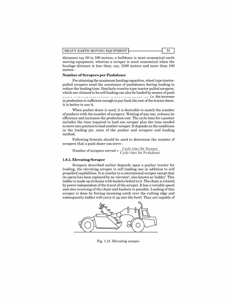
1.8.1. Elevating ScraperScrapers described earlier depends upon a pusher tractor for
loading, the elevating scraper is self loading one in addition to selfpropelled capabilities. It is similar to a conventional scraper except thatits apron has been replaced by an �elevator�, also known as �ladder�. Thisladder is made up of chains with buckets bolted to it. The chain is rotatedby power independent of the travel of the scraper. It has a variable speedand also reversing of the chain and buckets is possible. Loading of thisscraper is done by forcing incoming earth over the cutting edge andsubsequently ladder will carry it up into the bowl. They are capable of
Fig. 1.15. Elevating scraper.

CONSTRUCTION EQUIPMENT AND MANAGEMENT32
loading most materials except rock and boulders which are too large topass between the cutting edge and the elevator buckets, and cohesivematerial with high moisture content.
By using elevating scraper, cost of a pusher and its operator iseliminated. Elevating scrapers also have very good finishing ability, andhence very useful in preparing final layer of earth work in road or airfieldconstruction work.
The operating cost and maintenance cost of the elevating scraperis higher by nearly 30% as compared to that of conventional scrapers.Due to dead weight of the loading mechanism, its transportationefficiency is reduced.
Fig
. 1.1
6. E
leva
tin
g sc
rape
r (c
ourt
esy
: Joh
n d
eere
).

HEAVY EARTH MOVING EQUIPMENT 33
OperationOperation of an elevating scraper is described hereunder. The
working cycle is similar to that of conventional scraper.(i) Loading. For making a cut, the bowl is first lowered to a depth
which can permit the elevator and tractor to operate at high and constantengine speed. The cut will force material towards the bowl and elevatorbuckets will sweep the material into the bowl. The elevator has 4 forwardand one reverse speed. Soft surfaces like, sand, silt and topsoil are dugand loaded at high speeds. Low speeds are used for loading toughmaterials, like, hard clay etc. When the bowl is fully loaded, stop theelevator to avoid sweeping of the material from the face of the load andalso to avoid spilling over to sides of the bowl.
(ii) Transporting. When the scraper is loaded, the elevatorshould be stopped and bowl is raised until it clears the ground, movethe scraper and raise the bowl further during travelling. Transport thematerial to the place of dumping.
(iii) Unloading. The bowl is lowered to allow the desired depthof the spread. With the machine in motion, the ejector floor is opened,thus allowing the bowl to unload itself and the loading edge of the ejectorfloor will strike off the unloaded material in the bowl, in a smooth andeven layer.
When unloading is complete, the bowl can be raised, ejector flooris closed and the scraper is returned for the next cycle.
Optimising the Scraper ProductionFollowing are the some of the suggestions which will increase the
scraper production :(i) Construct and maintain smooth haul roads for faster and safer
travel with less driver fatigue.(ii) Depth of cut should be
according to the type ofsoil being handled.
(iii) Use ripper teeth in hardor abrasive materials foreasy loading. Whileripping a rock, the depthripped should be more soas to leave a loose layerof material under thetracks and tyres toprovide good tractionand reduced wear.
(iv) Where possible, loead-ing be done in downgrade.
Fig. 1.17. Figure-8 method ofloading and hauling.
CONSTRUCTION EQUIPMENT AND MANAGEMENT34
(v) To increase stability of the scraper during travel, carry thebowl as close to the ground as possible.
(vi) If necessary, pre-wetting of the soil is done so that soil isreasonably moist, since some soils will load more easily whenthey are moist.
(vii) Whenever possible, plan the work to eliminate all avoidableturns. For example, �Figure 8� loading, hauling, and unloadingcan be used to great advantage. By using this method, onlytwo turns are required while two full loads are delivered,whereas normally two turns are required for each load.
(viii) Dumping should be done in an orderly pattern in the lifts ofdesired thickness so that compaction equipment work in aneffective manner.
(ix) A spotter should always be employed to eliminate confusionand traffic congestion and coordinate the movement of scrapersfor spreading the soil in the fill and that of compactingequipment.
Advantages of Elevating ScrapersFollowing are the main advantages of elevating scrapers :(a) Better loading ability in loose free flowing materials.(b) Good finishing ability.(c) Can be operated independently.(d) Smooth and complete unloading of bowl by reversing the
elevator rotation.(e) Pusher tractor dozer is not required.(f) Addition of ripper teeth to the cutting edge permits self loading
in hard compacted material.(g) Pulverising and mixing action by the elevator places material
in uniform and homogeneous state for compaction.Special Types of Scrapers
Other than the tractor towed, motorised, and elevating scrapersexplained earlier, following are the other types of scrapers :
(i) Tandem Scrapers. In this type of scraper two bowls areattached to a single prime-mover unit. It gives higher capacity per cycle.
(ii) Twin Engine Scrapers. This type of scraper has two engineswith single bowl. This has the advantages of, (a) greater accelerationdue to higher power, (b) higher speeds under sever conditions, (c) lesschances for getting struck.
(iii)Multi-engine Multi-Bowl Scrapers. This is the combinationof the above two ideas. In these scrapers power is supplied to each wheel.These are generally self loading ; number of axles varies between 3 to 6,

HEAVY EARTH MOVING EQUIPMENT 35
number of bowls 3, capacity upto 80 cu m. This eliminates the need fora pusher.Output of Scrapers
Output of scrapers depends upon the following main factors :(i) Size and mechanical condition of the scraper.
(ii) Hauling distance.(iii) Condition of the haul road.(iv) Characteristics of soil and work area.(v) Efficiency.Heaped capacity of scraper out of the two scrapers having more
length or width and less height is higher even if the struck capacity issame.
Output of a scraper in bank-volume/hour.
= Optimum loose volume loaded/trip × S × 60t × Efficiency
where, S = Swell factor
and t = Cycle time/trip in minutes.
Cycle Time for a ScraperCycle time for a scraper is the time required for loading, hauling
to the fill, dumping, and returning back to the loading position. This cycletime is divided into : (i) Fixed time, which includes loading, dumping,turning, accelerating, retarding. These elements are reasonably constantunder uniform operating conditions. Generally time study data of suchelements are available for three type of conditions, namely favourable,average and unfavourable conditions. (ii) Variable time, which includeshauling and returning; it depends on the distance travelled and theaverage speed of the vehicle. This time is generally required to bedetermined.
1.9. LOADERSA bucket is attached to the arms and capable of being raised,
lowered and dumped through mechanical or hydraulic controls. Theloaders having bucket in the front, known as �Front-end loaders� are verycommon. The loaders are versatile, self propelled equipment mountedeither on crawler or wheel-type running gear. These loaders are fittedwith front mounted general-purpose bucket operated through hydraulicrams, with which they dig, scoop, lift, transport, carry, dump or load inohauling units, bins, hoppers, conveyors and stockpiles. With the help ofadditional front and rear mounted attachments these can doze, scrap,grub, fork-lift, trench, grade, ditch rip, clamp, and winch. Applicationsof a loader vary from handling coal, sugar, sand, salt, stone etc. to earthmoving and digging work in quarries.
CONSTRUCTION EQUIPMENT AND MANAGEMENT36
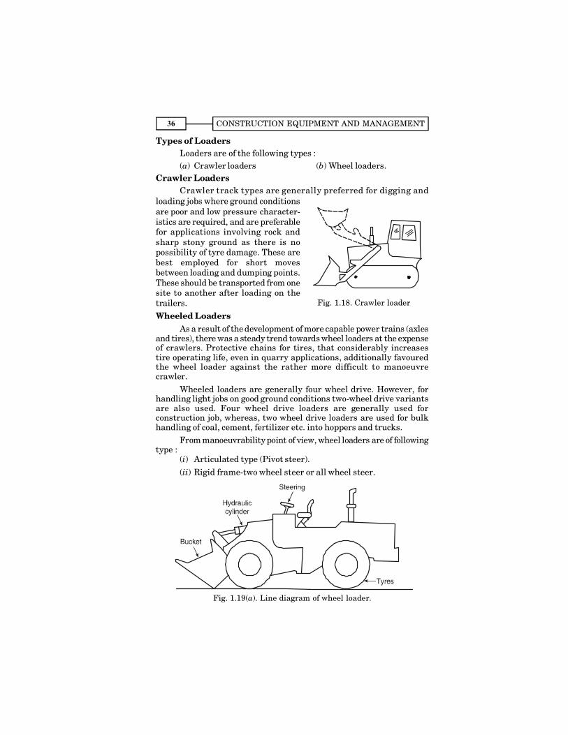
Types of LoadersLoaders are of the following types :(a) Crawler loaders (b) Wheel loaders.
Crawler LoadersCrawler track types are generally preferred for digging and
loading jobs where ground conditionsare poor and low pressure character-istics are required, and are preferablefor applications involving rock andsharp stony ground as there is nopossibility of tyre damage. These arebest employed for short movesbetween loading and dumping points.These should be transported from onesite to another after loading on thetrailers.Wheeled Loaders
As a result of the development of more capable power trains (axlesand tires), there was a steady trend towards wheel loaders at the expenseof crawlers. Protective chains for tires, that considerably increasestire operating life, even in quarry applications, additionally favouredthe wheel loader against the rather more difficult to manoeuvrecrawler.
Wheeled loaders are generally four wheel drive. However, forhandling light jobs on good ground conditions two-wheel drive variantsare also used. Four wheel drive loaders are generally used forconstruction job, whereas, two wheel drive loaders are used for bulkhandling of coal, cement, fertilizer etc. into hoppers and trucks.
From manoeuvrability point of view, wheel loaders are of followingtype :
(i) Articulated type (Pivot steer).(ii) Rigid frame-two wheel steer or all wheel steer.
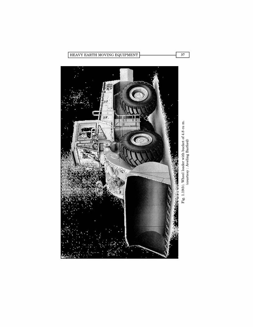
Fig. 1.19(a). Line diagram of wheel loader.
Fig. 1.18. Crawler loader
HEAVY EARTH MOVING EQUIPMENT 37
Fig
. 1.1
9(b)
. Wh
eel
load
er w
ith
buc
ket
of 4
.8 c
u m
.(c
ourt
esy
: A
veli
ng
Bar
ford
)
CONSTRUCTION EQUIPMENT AND MANAGEMENT38
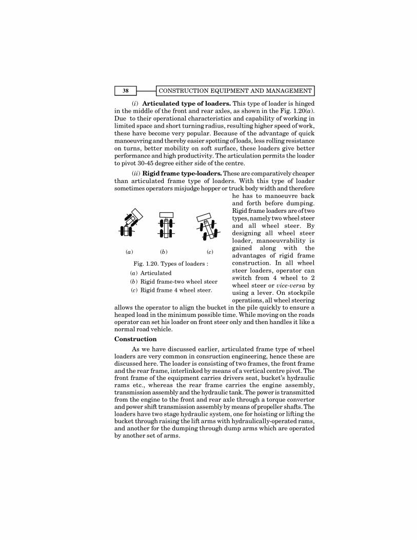
(i) Articulated type of loaders. This type of loader is hingedin the middle of the front and rear axles, as shown in the Fig. 1.20(a).Due to their operational characteristics and capability of working inlimited space and short turning radius, resulting higher speed of work,these have become very popular. Because of the advantage of quickmanoeuvring and thereby easier spotting of loads, less rolling resistanceon turns, better mobility on soft surface, these loaders give betterperformance and high productivity. The articulation permits the loaderto pivot 30-45 degree either side of the centre.
(ii) Rigid frame type-loaders. These are comparatively cheaperthan articulated frame type of loaders. With this type of loadersometimes operators misjudge hopper or truck body width and therefore
he has to manoeuvre backand forth before dumping.Rigid frame loaders are of twotypes, namely two wheel steerand all wheel steer. Bydesigning all wheel steerloader, manoeuvrability isgained along with theadvantages of rigid frameconstruction. In all wheelsteer loaders, operator canswitch from 4 wheel to 2wheel steer or vice-versa byusing a lever. On stockpileoperations, all wheel steering
allows the operator to align the bucket in the pile quickly to ensure aheaped load in the minimum possible time. While moving on the roadsoperator can set his loader on front steer only and then handles it like anormal road vehicle.
ConstructionAs we have discussed earlier, articulated frame type of wheel
loaders are very common in consruction engineering, hence these arediscussed here. The loader is consisting of two frames, the front frameand the rear frame, interlinked by means of a vertical centre pivot. Thefront frame of the equipment carries drivers seat, bucket�s hydraulicrams etc., whereas the rear frame carries the engine assembly,transmission assembly and the hydraulic tank. The power is transmittedfrom the engine to the front and rear axle through a torque convertorand power shift transmission assembly by means of propeller shafts. Theloaders have two stage hydraulic system, one for hoisting or lifting thebucket through raising the lift arms with hydraulically-operated rams,and another for the dumping through dump arms which are operatedby another set of arms.
(a) (b) (c)
Fig. 1.20. Types of loaders :
(a) Articulated(b) Rigid frame-two wheel steer(c) Rigid frame 4 wheel steer.
HEAVY EARTH MOVING EQUIPMENT 39
The hydraulically actuated loader lift mechanism is located infrontof the operator for safety reasons. Lift control provides raise, hold, lowerand float positions. Bucket control has roll-back, hold and dumppositions. Additional hydraulic controls are also proided for optionalattachment.
ApplicationsLoaders with its general purpose bucket and with additional
attachment can be used for :
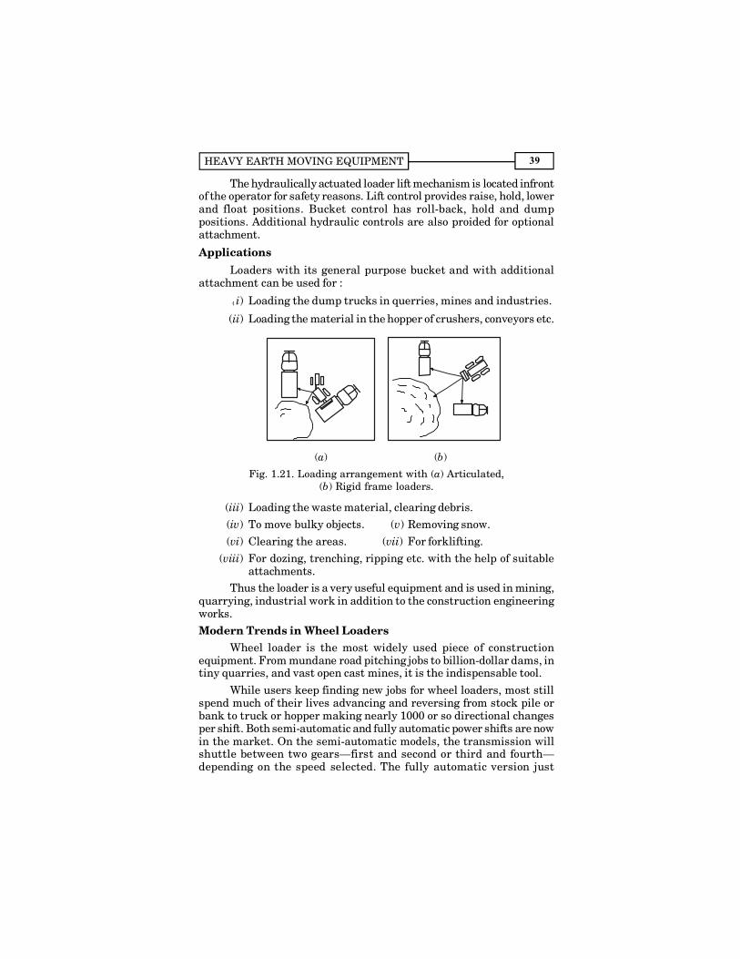
(( i) Loading the dump trucks in querries, mines and industries.
(ii) Loading the material in the hopper of crushers, conveyors etc.
(a) (b)
Fig. 1.21. Loading arrangement with (a) Articulated,(b) Rigid frame loaders.
(iii) Loading the waste material, clearing debris.(iv) To move bulky objects. (v) Removing snow.(vi) Clearing the areas. (vii) For forklifting.
(viii) For dozing, trenching, ripping etc. with the help of suitableattachments.
Thus the loader is a very useful equipment and is used in mining,quarrying, industrial work in addition to the construction engineeringworks.Modern Trends in Wheel Loaders
Wheel loader is the most widely used piece of constructionequipment. From mundane road pitching jobs to billion-dollar dams, intiny quarries, and vast open cast mines, it is the indispensable tool.
While users keep finding new jobs for wheel loaders, most stillspend much of their lives advancing and reversing from stock pile orbank to truck or hopper making nearly 1000 or so directional changesper shift. Both semi-automatic and fully automatic power shifts are nowin the market. On the semi-automatic models, the transmission willshuttle between two gears�first and second or third and fourth�depending on the speed selected. The fully automatic version just
CONSTRUCTION EQUIPMENT AND MANAGEMENT40
requires the operator to set the travel direction, and the transmissionhandles all the gear changing.
Few models have come into the market, on which, the hydraulictransmission works through a three-speed power shift gear box,providing infinitely variable speed upto more than 35 km/hr in top gear.The electro-hydraulically selected gear ratios and travel direction canbe selected under full power. A unique feature is the multi-function levelthat controls all bucket, gear selection, and travel direction functions.The system allows the operator to keep one hand on the steering wheelat all times, greatly enhancing safety.
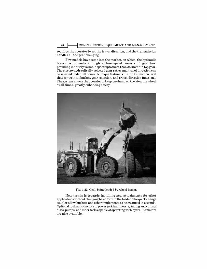
Fig. 1.22. Coal, being loaded by wheel loader.
New trends is towards installing new attachments for otherapplications without changing basic form of the loader. The quick changecoupler allow buckets and other implements to be swapped in seconds.Optional hydraulic circuits to power jack hammers, grinding and cuttingdiscs, pumps, and other tools capable of operating with hydraulic motorsare also available.
HEAVY EARTH MOVING EQUIPMENT 41
Developments in wheel loaders are also meeting the demands ofcustomers for improved noise protection, delux seats, electronicequipment, air conditioning and better layout of the machine.
Equipment manufacturers are trying for more efficient powertrain and hydraulic systems. The quantity of fuel needed per cubic metreof earth handled has declined. Tyre wear is being controlled bydifferential locks and rear axle disconnects for road travel, and stillsearch for better and better version is still going on.
OperationsLoaders are used to carry out following main operations :
(1) Loading. Loading operation is the main operation performedby the loaders. Loading consists of scooping, lifting, turning and dumping
(a)
(b)
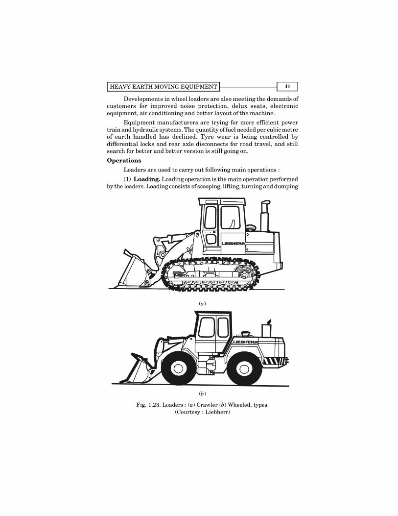
Fig. 1.23. Loaders : (a) Crawler (b) Wheeled, types.(Courtesy : Liebherr)
CONSTRUCTION EQUIPMENT AND MANAGEMENT42
materials such as sand, gravel and crushed materials from stockpiles,bank or construction site into the hauling units. For better output thebucket should be filled full and the number of hauling units deployedfor the work should be such that there is no waiting time for the loaderand there should not be more than one hauling unit in the Queue.
(2) Hauling. Wheel loaders are excellent for moving loosematerials over short distances to dump into hauling units, hoppers,conveyors, bins or any other place of work in the construction sites.
A cycle time for a loader consists of the following :(a) Time for scooping, lifting and dumping the bucket along with
time required for changing the directions and taking the turns.(b) Hauling time. It is the travel time for load carrying and empty
returning. Generally the high reverse speeds reduce thereturning time enabling the reduction in cycle time and thusmore work in one hour.
(3) Excavating. Crawler loaders and heavy duty wheel-loadersare excellent for many excavation jobs, like basement digging etc. Withexcavator attachment it can also handle several other types of excavationworks. These loaders can excavate as well as lift the excavated materialand dump it into trucks or on the stockpiles. In case surface is hard forexcavating and scooping, the earth ripper or sacrifier attachment ismounted on the rear of the loader to loosen such surface. The operatorcan then easily dig and load the material into bucket for removal.
(4) Clearing. Loaders can scoop up and load the debris ofdemolished buildings into hauling units. They also knock down smalland temporary buildings ; loaders are also used for clean up the areasafter snow-storms, tornadoes, floods etc. A grubber blade attachment isused in place of bucket for large-scale clearing work. Thus the loadersare the first equipment to prepare the site for building and constructionoperations; and also the last equipment in order to backfill, spread, leveland top up with selected good soil for grass and landscaping.Attachments
Following are the main attachments which can be fitted to a wheelloader :
(i) Back filling attachments. Backfilling can be done with thebucket of this attacment when used with the loader.
(ii) Fork lift attachment. An industrial fork lift when attachedwith a loader gives more stability, more tractive power and greaterclearance than with a normal fork lift truck.
(iii) Side bucket attachment. Side dump bucket is used to loadsnow for removal when work is required to be carried out in tight area.
HEAVY EARTH MOVING EQUIPMENT 43
By reducing the manoeuvring time, production in boosted by using thisattacment.
(iv) Sweeping attachment. A sweeping attachment can be fittedto a wheel loader for general cleaning of roads and parking area in theindustries.
(v) Multipurpose bucket. A multipurpos or four-in-one bucketcan be used as a dozer, scraper, clamshell and general purpose loading.The multipurpose bucket is much heavier than the general purposebucket, and therefore a loader equipped with it will generally need morecounter-weight for the same operating load rating.
(vi) Ripper-scarifier attachment. These are mounted on rearof the loader to loosen hard surfaces such as compacted earth ; hardpan,shale, slate, decomposed rock ; to tear up old brick, asphalt or brokenconcrete pavement, that do not readily yield to direct bucket loading.
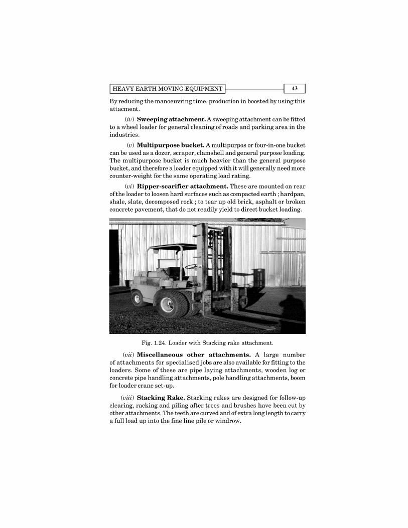
Fig. 1.24. Loader with Stacking rake attachment.
(vii) Miscellaneous other attachments. A large numberof attachments for specialised jobs are also available for fitting to theloaders. Some of these are pipe laying attachments, wooden log orconcrete pipe handling attachments, pole handling attachments, boomfor loader crane set-up.
(viii) Stacking Rake. Stacking rakes are designed for follow-upclearing, racking and piling after trees and brushes have been cut byother attachments. The teeth are curved and of extra long length to carrya full load up into the fine line pile or windrow.
CONSTRUCTION EQUIPMENT AND MANAGEMENT44
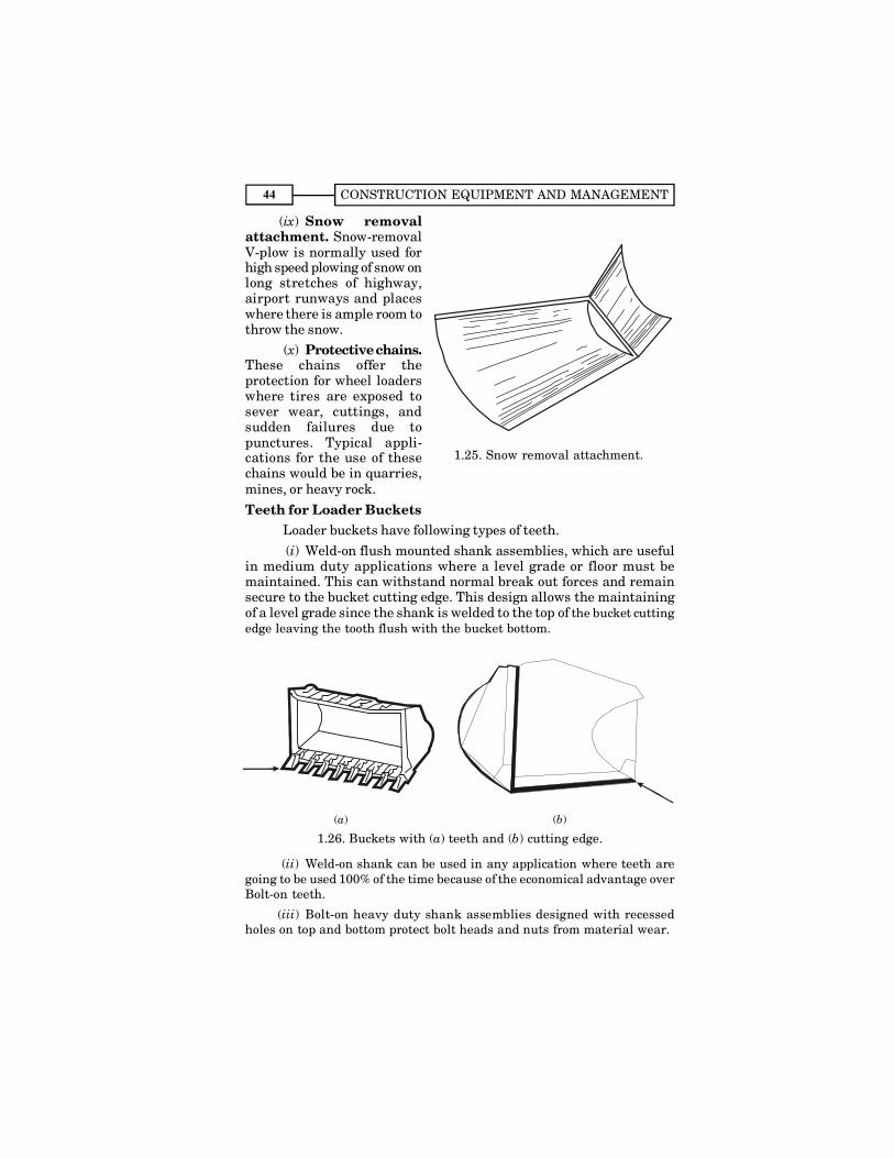
(ix) Snow removalattachment. Snow-removalV-plow is normally used forhigh speed plowing of snow onlong stretches of highway,airport runways and placeswhere there is ample room tothrow the snow.
(x) Protective chains.These chains offer theprotection for wheel loaderswhere tires are exposed tosever wear, cuttings, andsudden failures due topunctures. Typical appli-cations for the use of thesechains would be in quarries,mines, or heavy rock.Teeth for Loader Buckets
Loader buckets have following types of teeth.(i) Weld-on flush mounted shank assemblies, which are useful
in medium duty applications where a level grade or floor must bemaintained. This can withstand normal break out forces and remainsecure to the bucket cutting edge. This design allows the maintainingof a level grade since the shank is welded to the top of the bucket cuttingedge leaving the tooth flush with the bucket bottom.
(a) (b)
1.26. Buckets with (a) teeth and (b) cutting edge.
(ii) Weld-on shank can be used in any application where teeth aregoing to be used 100% of the time because of the economical advantage overBolt-on teeth.
(iii) Bolt-on heavy duty shank assemblies designed with recessedholes on top and bottom protect bolt heads and nuts from material wear.
1.25. Snow removal attachment.
HEAVY EARTH MOVING EQUIPMENT 45
(iv) Bolt-on teeth can be used for temporary digging in hard coal,shale or compacted materials etc. These teeth can easily be removedwhen they are not needed or when smooth grade work or clean-up workis required.
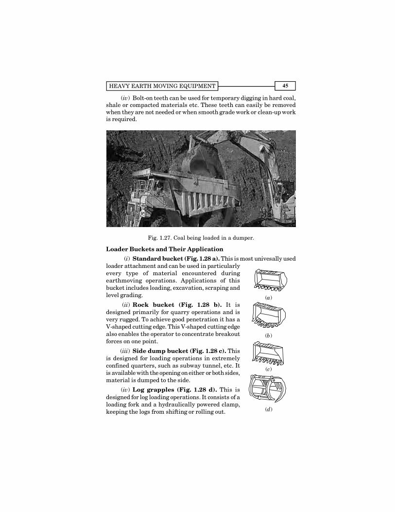
Fig. 1.27. Coal being loaded in a dumper.
Loader Buckets and Their Application(i) Standard bucket (Fig. 1.28 a). This is most univesally used
loader attachment and can be used in particularlyevery type of material encountered duringearthmoving operations. Applications of thisbucket includes loading, excavation, scraping andlevel grading.
(ii) Rock bucket (Fig. 1.28 b). It isdesigned primarily for quarry operations and isvery rugged. To achieve good penetration it has aV-shaped cutting edge. This V-shaped cutting edgealso enables the operator to concentrate breakoutforces on one point.
(iii) Side dump bucket (Fig. 1.28 c). Thisis designed for loading operations in extremelyconfined quarters, such as subway tunnel, etc. Itis available with the opening on either or both sides,material is dumped to the side.
(iv) Log grapples (Fig. 1.28 d). This isdesigned for log loading operations. It consists of aloading fork and a hydraulically powered clamp,keeping the logs from shifting or rolling out.
(a)
(b)
(c)
(d)

CONSTRUCTION EQUIPMENT AND MANAGEMENT46
(v) Stockpile bucket (Fig. 1.28 e). Thisperforms best when loading relatively light andnon-cohesive materials. It weighs less than astandard bucket and offers greater volumetriccapacity. Since it is used in stockpileenvironment, it is not equipped with teeth.
(e)Fig. 1.28. Loader
Buckets.
Fig
. 1.2
9. W
hee
l lo
ader
wit
h l
og g
rapp
le a
ttac
hm
ent
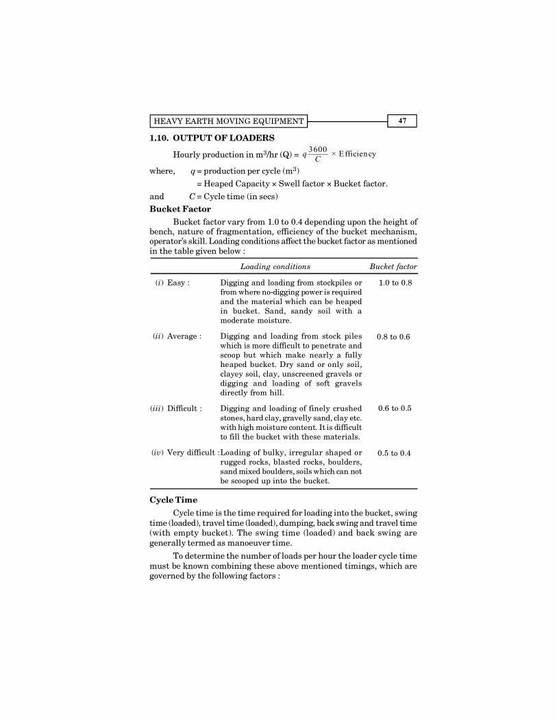
HEAVY EARTH MOVING EQUIPMENT 47
1.10. OUTPUT OF LOADERS
Hourly production in m3/hr (Q) = 3600 × Efficiencyq C
where, q = production per cycle (m3)= Heaped Capacity × Swell factor × Bucket factor.
and C = Cycle time (in secs)Bucket Factor
Bucket factor vary from 1.0 to 0.4 depending upon the height ofbench, nature of fragmentation, efficiency of the bucket mechanism,operator�s skill. Loading conditions affect the bucket factor as mentionedin the table given below :
Loading conditions Bucket factor
(i) Easy : Digging and loading from stockpiles orfrom where no-digging power is requiredand the material which can be heapedin bucket. Sand, sandy soil with amoderate moisture.
(ii) Average : Digging and loading from stock pileswhich is more difficult to penetrate andscoop but which make nearly a fullyheaped bucket. Dry sand or only soil,clayey soil, clay, unscreened gravels ordigging and loading of soft gravelsdirectly from hill.
(iii) Difficult : Digging and loading of finely crushedstones, hard clay, gravelly sand, clay etc.with high moisture content. It is difficultto fill the bucket with these materials.
(iv) Very difficult :Loading of bulky, irregular shaped orrugged rocks, blasted rocks, boulders,sand mixed boulders, soils which can notbe scooped up into the bucket.
Cycle TimeCycle time is the time required for loading into the bucket, swing
time (loaded), travel time (loaded), dumping, back swing and travel time(with empty bucket). The swing time (loaded) and back swing aregenerally termed as manoeuver time.
To determine the number of loads per hour the loader cycle timemust be known combining these above mentioned timings, which aregoverned by the following factors :
1.0 to 0.8
0.8 to 0.6
0.6 to 0.5
0.5 to 0.4

CONSTRUCTION EQUIPMENT AND MANAGEMENT48
(a) Loading time
Material Minutes
(i) Uniform aggregates 0.03 � 0.05(ii) Moist, mixed aggregates 0.04 � 0.06
(iii) Wet loam 0.05 � 0.07(iv) Roots, large rocks, soil 0.05 � 0.20(v) Extremely cohesive material 0.10 � 0.20
(b) Travel Time. In loader operation, travel time is a combinationof haul and return travel. For estimating the travel time manufacturer�schart is used.
(c)Swing time is the time required for moving the bucket fromone position to another keeping the height same. This time depends onthe degree and speed of swing and the skill of the operator. Swing timesare generally adopted as below :
Degree of swing Swing time, in seconds
45° to 90° 4�790° to 100° 5�8
(d) Dumping time is the time required for unloading the bucket,and depends on the proper spotting of transport equipment, and theoperator�s skill. Dumping at a fixed area requires 5 to 8 seconds, whileat an area not fixed requires 3 to 6 seconds.
Fig. 1.30. Wheel loader production in t/hr.
Wheel Loader Production. Fig. 1.30 gives a range of production
HEAVY EARTH MOVING EQUIPMENT 49
likely to be achieved with a particular size of bucket, depending uponthe cycle time. The chart is drawn considering the density of materialas 1.8 tons/m3
Loader CapacityFor general purpose, loaders with bucket sizes varying between
1.4 to 2.8 cubic metres are commonly used. However loaders upto 18 cumetres are also available for light materials handling. Engines withpower ranging between 65 to 250 B.H.P. are generally available.Capacities of the buckets are indicated by the struck capacity as wsellas heaped capacity. The crawler loaders use rock bucket for use in rocky,consolidated soils and are generally used for movements upto 50 metres(as compared to that of 300 metres in wheel loaders). Articulationpermitting 90° rotation of the bucket (45° to each side of the centre line)is available in most wheel loaders.
Increasing Loader Production
Loader production can be increased by adopting followingmethods :
(a) Blasting. Loosening of rock by blasting results in goodfragmentation which permits faster digging, greater payloads due tofewer voids, and also helps in increased crusher production with lesserstrains. Loosening of rock by blasting also reduces the danger of rockslides while the loader is in operation.
(b) Helping the Loader by a Dozer. Loader production can beincreased if it is spared from digging and collecting the material. Theseoperations if performed by a dozer, the loader is then allowed toconcentrate only on loading functions resulting in increased production.This is possible if either the quantum of work is very heavy or a dozerworking in the area is not fully occupied.
(c) Planning the work. Locating the dumpers, and place in thestockpile from where it takes the material for loading greatly effect theloading cycle time. This should be carried out in such a way that cycletime is kept minimum. During idle time i.e. when it is not loading, theloader should be used to work a stockpile, clean the area in order to savethe tyres of hauling units. If idle time is long, it can be used to maintainhaul roads and other jobs which can be performed by the loader includingthose with special attachments.
1.11. BELT LOADERSBelt loaders consist of a cutting edge and a conveyor belt, which
either discharge excavated earth on the side of the belt loader or crossesmachine towards the rear to load into the carriers located there. Thematerial cut by the blade is thrown over the lower end of the conveyorbelt to carry it over to discharge into the hauling units or thrown to theside into windrows. Generally soft materials are handled by these loaders.
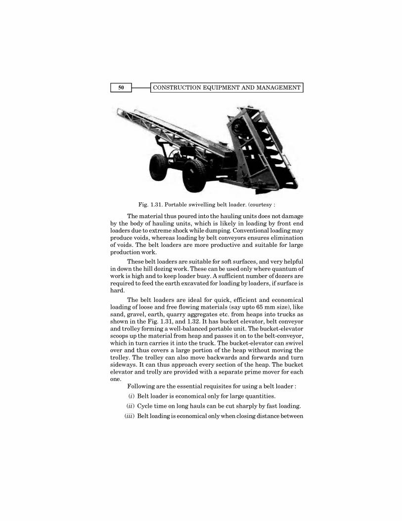
CONSTRUCTION EQUIPMENT AND MANAGEMENT50
Fig. 1.31. Portable swivelling belt loader. (courtesy :
The material thus poured into the hauling units does not damageby the body of hauling units, which is likely in loading by front endloaders due to extreme shock while dumping. Conventional loading mayproduce voids, whereas loading by belt conveyors ensures eliminationof voids. The belt loaders are more productive and suitable for largeproduction work.
These belt loaders are suitable for soft surfaces, and very helpfulin down the hill dozing work. These can be used only where quantum ofwork is high and to keep loader busy. A sufficient number of dozers arerequired to feed the earth excavated for loading by loaders, if surface ishard.
The belt loaders are ideal for quick, efficient and economicalloading of loose and free flowing materials (say upto 65 mm size), likesand, gravel, earth, quarry aggregates etc. from heaps into trucks asshown in the Fig. 1.31, and 1.32. It has bucket elevator, belt conveyorand trolley forming a well-balanced portable unit. The bucket-elevatorscoops up the material from heap and passes it on to the belt-conveyor,which in turn carries it into the truck. The bucket-elevator can swivelover and thus covers a large portion of the heap without moving thetrolley. The trolley can also move backwards and forwards and turnsideways. It can thus approach every section of the heap. The bucketelevator and trolly are provided with a separate prime mover for eachone.
Following are the essential requisites for using a belt loader :
(i) Belt loader is economical only for large quantities.
(ii) Cycle time on long hauls can be cut sharply by fast loading.
(iii) Belt loading is economical only when closing distance between
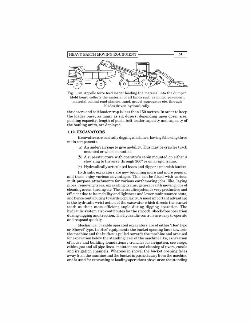
HEAVY EARTH MOVING EQUIPMENT 51
Fig. 1.32. Appollo force feed loader loading the material into the dumper.Mold board collects the material of all kinds such as milled pavement,
material behind road planers, sand, gravel aggregates etc. throughblades driven hydraulically.
the dozers and belt loader trap is less than 150 metres. In order to keepthe loader busy, as many as six dozers, depending upon dozer size,pushing capacity, length of push, belt loader capacity and capacity ofthe hauling units, are deployed.
1.12. EXCAVATORSExcavators are basically digging machines, having following three
main components.(( a) An undercarriage to give mobility. This may be crawler track
mounted or wheel mounted.(b) A superstructure with operator�s cabin mounted on either a
slew ring to traverse through 360° or on a rigid frame.(c) Hydraulically articulated boom and dipper arms with bucket.Hydraulic excavators are now becoming more and more popular
and these enjoy various advantages. This can be fitted with variousmultipurpose attachments for various earthmoving jobs, like, layingpipes, removing trees, excavating drains, general earth moving jobs ofcleaning areas, loading etc. The hydraulic system is very productive andefficient due to its mobility and lightness and lower maintenance costs,and hence contributing towards popularity. A most important advantageis the hydraulic wrist action of the excavator which directs the bucketteeth at their most efficient angle during digging operation. Thehydraulic system also contributes for the smooth, shock-free operationduring digging and traction. The hydraulic controls are easy to operateand respond quickly.
Mechanical or cable operated excavators are of either �Hoe� typeor �Shovel� type. In �Hoe� equipments the bucket opening faces towardsthe machine and the bucket is pulled towards the machine and are usedfor excavation below the standing level of the machine like, excavationof house and building foundations ; trenches for irrigation, sewerage,cables, gas and oil pipe lines ; maintenance and cleaning of rivers, canalsand irrigation channels. Whereas in shovel the bucket opening facesaway from the machine and the bucket is pushed away from the machineand is used for excavating or loading operations above or on the standing

CONSTRUCTION EQUIPMENT AND MANAGEMENT52
level of the machine i.e. for excavating of rock or earth ; loading ofmaterial like earth, coal, aggregate etc. �Hoe� and �Shovel� are describedseparately in this book in the chapter on �Shovels and Cranes�.Types of Excavators
Excavators are of following four types based on the type of carrierson which they are mounted :
(a) Crawler mounted excavator.(b) Truck mounted excavator.(c) Self propelled excavator.(d) Excavators mounted on barge or rail.(a) Crawler Mounted Excavator. These excavators are
mounted on the crawler system and are very suitable for carrying outlarge works in rough terrain. Crawler excavators have following maincharacterisics :
(i) Can be used for work on soft or wet grounds.(ii) Can be used on sharp rocks or other adverse conditions.
(iii) These can climb steep grades (even upto 40 per cent).(iv) Requires very less turning space.(v) Have very less speed for travelling.
(vi) Can be shifted from one site to another only on trailers.(b) Truck Mounted Excavators. These excavators are mounted
on truck chasis and has following main characteristics :(i) High road speed and mobility is the main advantage.
(ii) Lower stability over sides and hence require counter-weightor outriggers.
(iii) Require more operating space.(iv) Tyres or outriggers give high ground pressure and hence it
requires firm and smooth operating locations.(v) Have two engines and two cabs, separately for truck chasis
and excavator.(c) Self Propelled Excavators. These excavators are self
proeplled and has rubber tyres. The main characteristics are :(i) Medium travel speed generally between 10 to 30 km per hour.
(ii) Has one engine and one cab for control by one operator.
(d) Excavators on Barge or Rail. These excavators are mountedon barge or rail to carry out work of excavation in water or near railwayline respectively.
Excavator CapacityExcavators of sizes between 0.5 � 4 cubic metre bucket capacity
are commonly used for various excavation purposes.
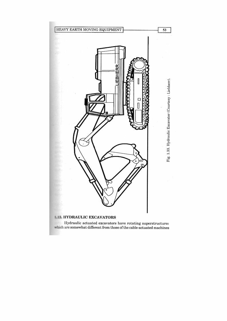

CONSTRUCTION EQUIPMENT AND MANAGEMENT54
like back hoe, power-shovel, dragline and clamshell (explained in nextchapter). However, attachments of backhoes, straight line telescopichoes, and telescopic boom lift cranes are available for mounting onhydraulic-actuated exvacator. This increases the suitability,applicability and popularity of hydraulic excavators.
Fig. 1.34. Hydraulic excavator in loading operation(Courtesy : Liebherr)
The various digging actions are powered by hydraulic cylindersand motors and are controlled by hydraulic valves or variable-strokepumps. The hydraulic excavator has the advantages that its diggingforces do not tend to lift the bucket out of a deep trench, as does the cablepull on a cable-powered hoe. But hydraulic excavators need slightlylarger engine as compared to that of cable operated, because hydraulicpumps are slightly less efficient than gear and chain drive, and also dueto pressure drop in line and valve.
Hydraulic excavators are troubled by gradual erosion of pumpsand valves from fine dirt or by sudden failures due to large metalparticles in the oil flow. Oil filteration is therefore very important. Careshould also be taken that, foam or air must not be pulled into the pumpsbecause air even in minute quantities can soon destroy a pump.
Now-a-days hydraulic excavators of various sizes upto 30 m3
bucket capacity and 1730 kW engine output are available. These largesized, heavy hydraulic excavators are mostly used in exploitation of rawmaterials, open cast mining, for loosening and loading of large materialquantities, and where transport vehicles of adequate size can beeconomically employed.
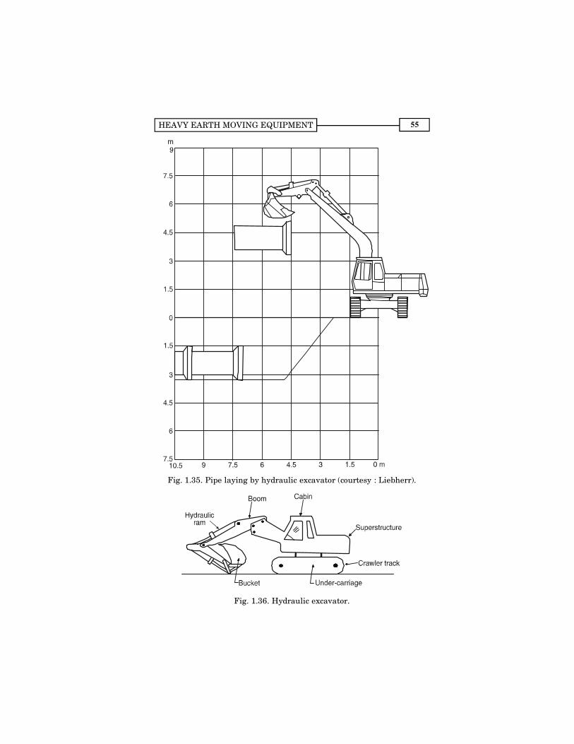
HEAVY EARTH MOVING EQUIPMENT 55
Fig. 1.35. Pipe laying by hydraulic excavator (courtesy : Liebherr).
Fig. 1.36. Hydraulic excavator.
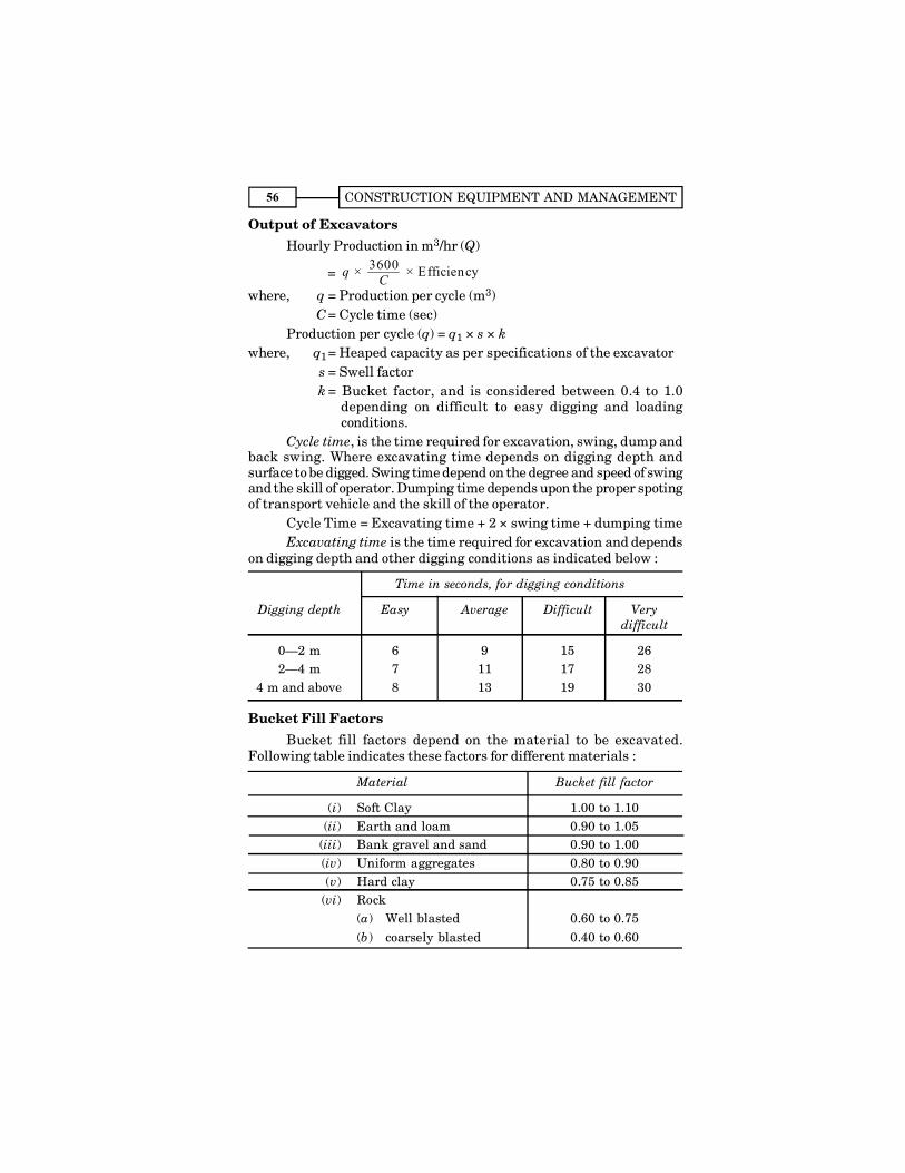
CONSTRUCTION EQUIPMENT AND MANAGEMENT56
Output of ExcavatorsHourly Production in m3/hr (Q)
= 3600 × × Efficiencyq C
where, q = Production per cycle (m3) C= Cycle time (sec)Production per cycle (q) = q1 × s × k
where, q1= Heaped capacity as per specifications of the excavator s = Swell factor
k = Bucket factor, and is considered between 0.4 to 1.0depending on difficult to easy digging and loadingconditions.
Cycle time, is the time required for excavation, swing, dump andback swing. Where excavating time depends on digging depth andsurface to be digged. Swing time depend on the degree and speed of swingand the skill of operator. Dumping time depends upon the proper spotingof transport vehicle and the skill of the operator.
Cycle Time = Excavating time + 2 × swing time + dumping timeExcavating time is the time required for excavation and depends
on digging depth and other digging conditions as indicated below :
Time in seconds, for digging conditions
Digging depth Easy Average Difficult Verydifficult
0�2 m 6 9 15 262�4 m 7 11 17 28
4 m and above 8 13 19 30
Bucket Fill FactorsBucket fill factors depend on the material to be excavated.
Following table indicates these factors for different materials :
Material Bucket fill factor
(i) Soft Clay 1.00 to 1.10(ii) Earth and loam 0.90 to 1.05
(iii) Bank gravel and sand 0.90 to 1.00(iv) Uniform aggregates 0.80 to 0.90(v) Hard clay 0.75 to 0.85
(vi) Rock(a) Well blasted 0.60 to 0.75(b) coarsely blasted 0.40 to 0.60

HEAVY EARTH MOVING EQUIPMENT 57
Optimizing Excavator ProductionAs we know that for increasing the excavator production, loading
cycle should be reduced. Therefore, following are the some of thesuggestions which will increase the excavator production, by adoptingideal backhoe applications, as shown in Fig. 1.37.
Fig. 1.37 (a). Short swing angles and low material hoisting.
Fig. 1.37 (b). Fastest possible truck exchange for high hourly production.
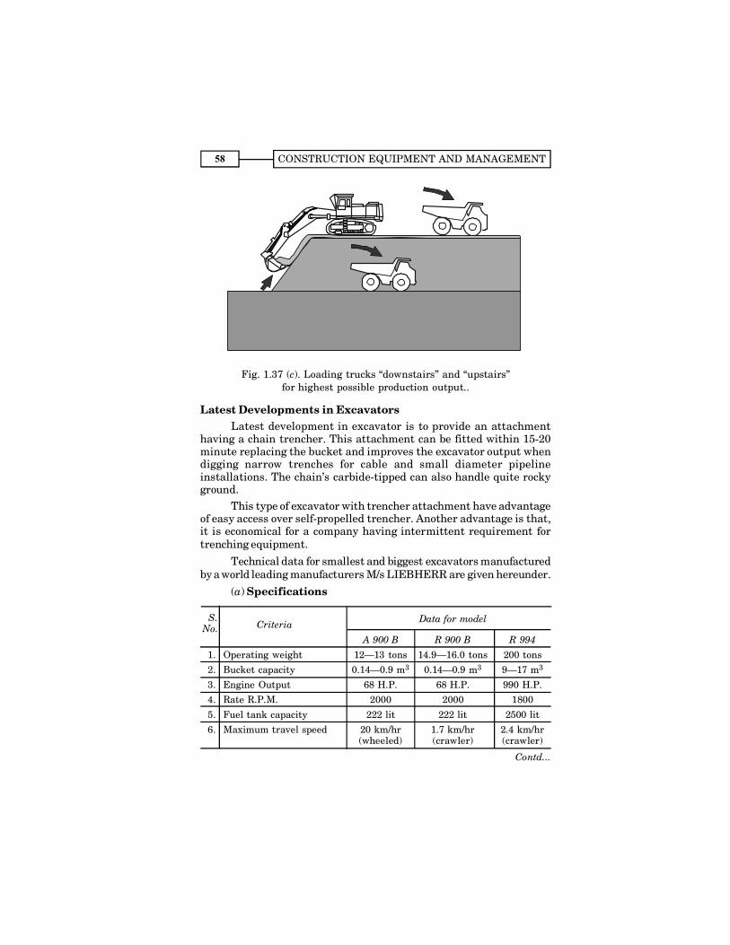
CONSTRUCTION EQUIPMENT AND MANAGEMENT58
Fig. 1.37 (c). Loading trucks �downstairs� and �upstairs�for highest possible production output..
Latest Developments in ExcavatorsLatest development in excavator is to provide an attachment
having a chain trencher. This attachment can be fitted within 15-20minute replacing the bucket and improves the excavator output whendigging narrow trenches for cable and small diameter pipelineinstallations. The chain�s carbide-tipped can also handle quite rockyground.
This type of excavator with trencher attachment have advantageof easy access over self-propelled trencher. Another advantage is that,it is economical for a company having intermittent requirement fortrenching equipment.
Technical data for smallest and biggest excavators manufacturedby a world leading manufacturers M/s LIEBHERR are given hereunder.
(a) Specifications
Criteria
A 900 B R 900 B R 994
1. Operating weight 12�13 tons 14.9�16.0 tons 200 tons2. Bucket capacity 0.14�0.9 m3 0.14�0.9 m3 9�17 m3
3. Engine Output 68 H.P. 68 H.P. 990 H.P.4. Rate R.P.M. 2000 2000 1800
5. Fuel tank capacity 222 lit 222 lit 2500 lit6. Maximum travel speed 20 km/hr 1.7 km/hr 2.4 km/hr
(wheeled) (crawler) (crawler)
S.No.
Data for model
Contd...
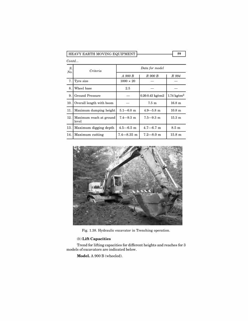
HEAVY EARTH MOVING EQUIPMENT 59
7. Tyre size 1000 × 20 � �
8. Wheel base 2.5 � �
9. Ground Pressure � 0.26-0.43 kg/cm2 1.74 kg/cm2
10. Overall length with boom � 7.5 m 16.8 m
11. Maximum dumping height 5.1�6.0 m 4.9�5.8 m 10.8 m
12. Maximum reach at ground 7.4�9.3 m 7.5�9.3 m 15.3 mlevel
13. Maximum digging depth 4.5�6.5 m 4.7�6.7 m 8.5 m
14. Maximum cutting 7.4�8.35 m 7.2�8.0 m 15.8 m
Fig. 1.38. Hydraulic excavator in Trenching operation.
(b) Lift Capacities
Trend for lifting capacities for different heights and reaches for 3models of excavators are indicated below.
Model. A 900 B (wheeled).
Contd...
S.No. Criteria
A 900 B R 900 B R 994
Data for model

CONSTRUCTION EQUIPMENT AND MANAGEMENT60
Outrigger Reach
configuration 3 m 4.5 m 6.1 m
6.1 m (a) Without 2.9 T 1.8 T
(b) With 3.3 T 2.6 T
3 m (a) Without 2.5 T 1.6 T
(b) With 3.8 T 2.4 T
1.5 m (a) Without 2.3 T 1.5 T
(b) With 3.6 T 2.3 T
Ground level (a) Without 2.3 T 1.5 T
(b) With 3.6 T 2.3 T
� 1.5 m (a) Without 4.3 T 2.3 T 1.5 T
(b) With 5.8 T 3.5 T 2.3 T
� 3 m (a) Without 2.3 T �
(b) With 2.3 T �
Fig. 1.39. Side shift backhoe hydraulic excavator to dig a straight walltrench on either side of tractor centre.
Height
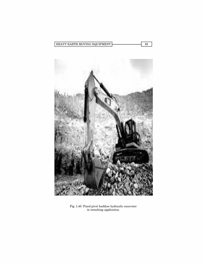
HEAVY EARTH MOVING EQUIPMENT 61
Fig. 1.40. Fixed pivot backhoe hydraulic excavatorin trenching application.
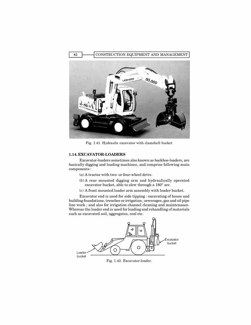
CONSTRUCTION EQUIPMENT AND MANAGEMENT62
Fig. 1.41. Hydraulic excavator with clamshell bucket
1.14. EXCAVATOR-LOADERSExcavator-loaders sometimes also known as backhoe-loaders, are
basically digging and loading machines, and comprise following maincomponents :
(a) A tractor with two- or four-wheel drive.(b) A rear mounted digging arm and hydraulically operated
excavator bucket, able to slew through a 180° arc.(c) A front mounted loader arm assembly with loader bucket.Excavator end is used for side tipping : excavating of house and
building foundations, trenches or irrigation ; sewerages, gas and oil pipeline work ; and also for irrigation channel cleaning and maintenance.Whereas the loader end is used for loading and rehandling of materialssuch as excavated soil, aggregates, coal etc.
Fig. 1.42. Excavator-loader.
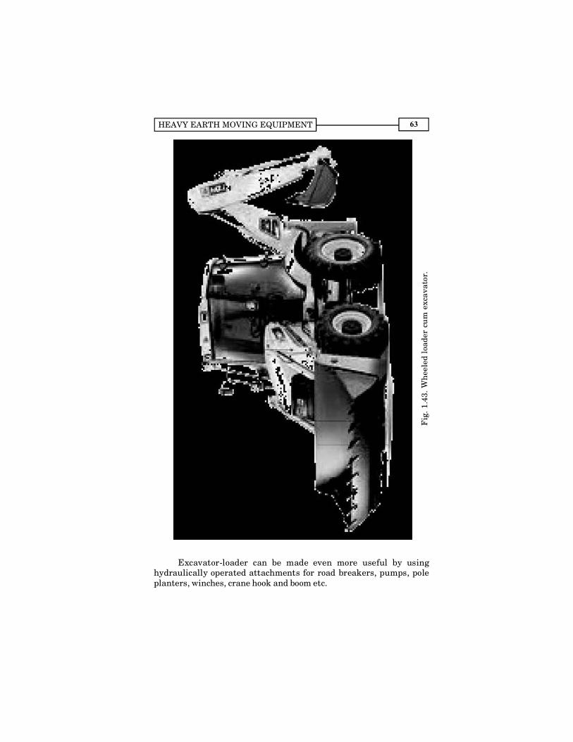
HEAVY EARTH MOVING EQUIPMENT 63
Excavator-loader can be made even more useful by usinghydraulically operated attachments for road breakers, pumps, poleplanters, winches, crane hook and boom etc.
Fig
. 1.4
3. W
hee
led
load
er c
um
exc
avat
or.
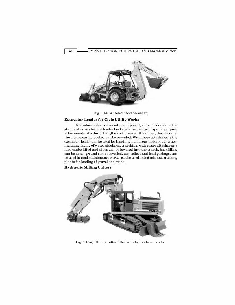
CONSTRUCTION EQUIPMENT AND MANAGEMENT64
Fig. 1.44. Wheeled backhoe-loader.
Excavator-Loader for Civic Utility WorksExcavator-loader is a versatile equipment, since in addition to the
standard excavator and loader buckets, a vast range of special purposeattachments like the forklift,the rock breaker, the ripper, the jib crane,the ditch clearing bucket, can be provided. With these attachments theexcavator loader can be used for handling numerous tasks of our cities,including laying of water pipelines, trenching, with crane attachmentsload canbe lifted and pipes can be lowered into the trench, backfillingcan be done, ground can be levelled, can collect and load garbage, canbe used in road maintenance works, can be used on hot mix and crushingplants for loading of gravel and stone.
Hydraulic Milling Cutters
Fig. 1.45(a). Milling cutter fitted with hydraulic excavator.
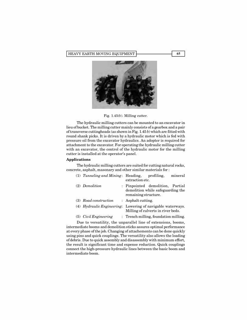
HEAVY EARTH MOVING EQUIPMENT 65
Fig. 1.45(b). Milling cutter.
The hydraulic milling cutters can be mounted to an excavator inlieu of bucket. The milling cutter mainly consists of a gearbox and a pairof transverse cuttingheads (as shown in Fig. 1.45 b) which are fitted withround shank picks. It is driven by a hydraulic motor which is fed withpressure oil from the excavator hydraulics. An adopter is required forattachment to the excavator. For operating the hydraulic milling cutterwith an excavator, the control of the hydraulic motor for the millingcutter is installed at the operator�s panel.
ApplicationsThe hydraulic milling cutters are suited for cutting natural rocks,
concrete, asphalt, masonary and other similar materials for :
(1) Tunneling and Mining : Heading, profiling, mineralextraction etc.
(2) Demolition : Pinpointed demolition, Partialdemolition while safeguarding theremaining structure.
(3) Road construction : Asphalt cutting.
(4) Hydraulic Engineering: Lowering of navigable waterways.Milling of culverts in river beds.
(5) Civil Engineering : Trench milling, foundation milling.
Due to versatility, the unparallel line of extensions, booms,intermediate booms and demolition sticks assures optimal performanceat every phase of the job. Changing of attachements can be done quicklyusing pins and quick couplings. The versatility also allows the loadingof debris. Due to quick assembly and disassembly with minimum effort,the result is significant time and expense reduction. Quick couplingsconnect the high-pressure hydraulic lines between the basic boom andintermediate boom.

CONSTRUCTION EQUIPMENT AND MANAGEMENT66
1.15. BUCKET-WHEEL EXCAVATORBucket wheel excavator consists of a digging wheel having buckets
can be adjusted vetically by means of hydraulic rams. The wheel ismounted on a boom, having a conveyor belt on which this wheeldischarges. This boom together with digging wheel and conveyor canswing through a complete 360° circle by rotating on the crawler-mountedor wheel mounted undercarriage. A second conveyor, which is colinear,with the first, receives material from the first conveyor. Although thedischarge point of the first is fixed relatively to the loading point of thesecond conveyor. The second conveyor can be hydraulically slewedthrough an arc of 180° and can be raised and lowered hydraulically toaccommodate receiving hauling units of varying heights.
The power for each of the conveyor, digging wheel, the crawlersand to rotate the superstructure is provided by individual electric motors.These motors, inturn are driven by the main prime-mover. Singleoperator controls all the functions of the excavator from the cabin.
Bucket wheel ex-cavator of various sizesranging from 200 cu m to11000 cu m/hr aremanufactured. Wheels ofdiameter upto 15 metresare manufactures forexcavation. This type ofwheel excavator isgenerally used for miningwork.
1.16. SNOW-CLEARING EQUIPMENTClearance of snow from construction sites and access roads was
earlier done through specialised and expensive machines. It is nowpossible by converting standard construction machinery into economicaland effective units for the removal of snow. This is done by providingspecial attachmenets. An attachment for cutting and blowing the snowis provided with a tractor and can be inter-changed with the angle-dozeretc. The snow blowers have a capacity of 1000 to 2400 tons/hr dependingupon the tractor�s horsepower. The blowers have either a single or dualhydrostatic motor input to power the single stage, dual impeller design,and does not require any auxiliary engine. The dual fans are combinationof cutters and blowers with 12 wear resistant and hardened steel teethto provide a milling effect on frozen and hard packed snow.
1.17. TRENCHING MACHINESThese machines are used for digging trenches at a faster rate and
with proper control of depths and widths, and are capable of digging any
Fig. 1.46. Bucket wheel excavator.
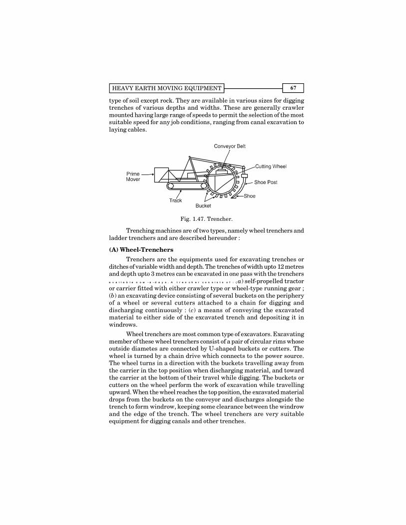
HEAVY EARTH MOVING EQUIPMENT 67
type of soil except rock. They are available in various sizes for diggingtrenches of various depths and widths. These are generally crawlermounted having large range of speeds to permit the selection of the mostsuitable speed for any job conditions, ranging from canal excavation tolaying cables.
Fig. 1.47. Trencher.
Trenching machines are of two types, namely wheel trenchers andladder trenchers and are described hereunder :
(A) Wheel-TrenchersTrenchers are the equipments used for excavating trenches or
ditches of variable width and depth. The trenches of width upto 12 metresand depth upto 3 metres can be excavated in one pass with the trenchersaa vv aa ii ll aa bb ll ee nn oo ww -- aa -- dd aa yy ss .. AA tt rr ee nn cc hh ee rr cc oo nn ss ii ss tt ss oo ff :: (( a) self-propelled tractoror carrier fitted with either crawler type or wheel-type running gear ;(b) an excavating device consisting of several buckets on the peripheryof a wheel or several cutters attached to a chain for digging anddischarging continuously : (c) a means of conveying the excavatedmaterial to either side of the excavated trench and depositing it inwindrows.
Wheel trenchers are most common type of excavators. Excavatingmember of these wheel trenchers consist of a pair of circular rims whoseoutside diametes are connected by U-shaped buckets or cutters. Thewheel is turned by a chain drive which connects to the power source.The wheel turns in a direction with the buckets travelling away fromthe carrier in the top position when discharging material, and towardthe carrier at the bottom of their travel while digging. The buckets orcutters on the wheel perform the work of excavation while travellingupward. When the wheel reaches the top position, the excavated materialdrops from the buckets on the conveyor and discharges alongside thetrench to form windrow, keeping some clearance between the windrowand the edge of the trench. The wheel trenchers are very suitableequipment for digging canals and other trenches.
CONSTRUCTION EQUIPMENT AND MANAGEMENT68
The trenches may be for water, gas and oil pipe lines, telephonecables, drainage and sewers. These provide for digging with positivecontrol over depths and widths of trenches and needs minimum effortsfor finishing. These can dig any type of soil except rock, and are availablein various sizes for digging trenches of varying depths and widths.
Selection of trenchersThe selection of a trenching equipment depend on the job
conditions, depth and width of the trench, type of soil, disposal ofexcavated earth, availability of ground water.
(B) Ladder-type Trenching MachinesIn these machines buckets are provided with chain links on ladder
type frame or boom. By providing extensions to these ladders and byadding more buckets, it can dig trenches upto 10 meter depth. Thesemachines are used where depth of trench required is more than 3 metres.Width of the trench can be increased by installing shaft mounted sidecutters on each side of the boom. As the bucket travel up the undersideof the boom, they bring out earth & unload it on a belt conveyor whichdischarges this excavated earth along either side of the trench like wheeltype trenching machines.
The ladder turns about two pivot points in its elliptical path. Thismakes for a flatter, more compact arrangement, and the depth ofexcavation is not restricted by wheel diameter. For slit trenching, thereis chain line which carries cutting blades along its periphery like a chainsaw. The blades are available in different lengths depending upon thewidth of the trench desired. For hard ground like concrete or rock-studedground, tungsten carbide teeth are used.
Advantages in Using a TrencherBy using a trencher following advantages can be achieved :
(a) It is faster and cheaper method of trenching.
(b) It digs only as much as is necessary. A 10-cm pipe can beinstalled in a 15 cm wide slot cut by a trencher.
(c) It is a continuous process and is not like that of back-hoeexcavator i.e. dug-lift-dump.
1.18. WORKING CONDITIONS FOR OPTIMUM UTILISATIONOF H.E.M. EQUIPMENTIn addition to the availability of spares, proper maintenance and
operating skill, optimum utilisation of Heavy Earth Moving Equipmentdepends upon actual working conditions. Factors related to workingconditions are discussed hereunder :
(i) Proper Fragmentation. Fragmentation of the rock pieceshould be appropriate so that bucket is filled fully.
HEAVY EARTH MOVING EQUIPMENT 69
(ii) Ripping. The rock should be loose enough otherwise rippersshould be used so as to enable it to be loaded by front end loader.
(iii) Capacity to match the specific gravity of rock. Dumpersand loader buckets have capacity in terms of tonnes of the rock carriedby them. In order to utilise full capacity, it should be sufficient in sizeso as to load it fully in terms of weight. A dumper meant for iron ore ifused for coal, will utilise only 1/3rd of its capacity.
(iv) Proper Height for Excavation. Excavator/shovels hasoptimum digging heights, therefore these should be used in such a waythat excavation is always carried out for optimum heights.
(v) Manoeuvrability. Excavating area should be managed insuch a way that minimum time is wasted in manoeuvrability.
(vi) Gradient. The hauld road should not have too much gradient.
(vii) Condition of Hauled Roads. In order to save time inhaulage, the haul road should be properly maintained. Properlymaintained road means free from unevenness, sharp bends, ruts, ditches,boulders etc. lying on the road, with sufficient road width. The roadshould be maintained by sprinkling water, compacting and using themotor grader. This saves from the dust and allows the vehicle to movewith more speed. Large projects have permanent haul roads. Theincrease in efficiency, less break down and more production due to lesscycle time prove this as economical.
QUESTIONS
1. Justify the statement, �Tractor is a basic equipment for earthmoving machinery�. Describe its construction in brief.
2. List out applications of a bulldozer.
3. Describe �dozing� and �ripping action by bulldozers.
4. Describe construction and working of scrapers.
5. Describe construction and working of elevating scraper.Differentiate it with conventional scrapers.
6. Illustrate various applications of loaders. Mention merits anddemerits of wheel loaders and crawler loaders.
7. What is an excavator ? Describe working of a hydraulic excavator.Mention its applications.
8. Write short notes on :
(a) Use of scraper as a construction equipment,
(b) Trenching machines.
9. Explain the relative advantages and disadvantages of a �crawlertractor� and a �wheel tractor�.
CONSTRUCTION EQUIPMENT AND MANAGEMENT70
10. What are the operations that can be performed by bulldozers ?Describe briefly the procedure for clearing of an area withbulldozer.
11. Discuss the factors which influence the output of earth movingmachinery.
12. What is a tractor ? For what purposes it is used ?
13. What factors influence the selection of a tractor ? Explain in brief.
14. How the power is supplied to the dozers ?
15. Write a note on the blades of a dozer.
16. What is meant by rock ripping ? How the rippability of rocks isdetermined ?
17. What is a scrapper ? Discuss dozer pulled scrapers.
18. Give the classification of scrappers and discuss them in brief.
19. Explain different types of ripper attachments with sketch.
20. Write short notes on :
(a) Types of dozer blades (b) Output of bulldozer
21. How would you calculate the output of rippers? How would youincrease the ripping production from a dozer?
22. Suggest methods for increasing the scraper production.
23. Write short notes on the following :
(a) Advantages of elevating scrapers.
(b) Cycle time for a scraper. (c) Articulated type of loaders.
(d) Loader applications.
24. Explain different types of wheel loader attachments.
25. Explain different types of loader buckets and their applications.
26. How would you calculate loader output? Suggest methods forincreasing the loader production.
27. Explain the following in brief :
(a) Belt loader (b) Types of excavators.
(c) Output of excavator.
28. What is an excavator-loader? Explain various applications ofexcavator-loader.
29. Explain the following in brief :
(a) Bucket-wheel excavator. (b) Snow-clearing equipment.
(c) Wheel-trenchers.