hdm-944s50thanksbuyer.com/.../50431-hdm-944f-user-manual-v1.3.docx · web viewhdmi&vga&av...
TRANSCRIPT

HDMI&VGA&AV mixed inputs
Video Processing Matrix switcher 4x4
Operation Manual

1.IntroductionThe matrix switcher is a high-performance with seamless switching output and mixed input 4x4 matrix switcher,4 mixed input to support digital video signals and analog video signal, and 4 outputs with seamless switching function, seamless switching mode: fast switching, fade in/fade out, blinds and so on; the mixing matrix switcher adopts the advanced digital technology, with scaler function, and achieve a variety of formats to achieve a unified output signal, switching seamlessly perfect visual effects. At the same time it with infrared matrix function, analog video signal input with embedded audio function. Flexible control mode diversity, through the front panel button, remote control,RS-232 and TCP/IP control.As a video wall processor, the matrix switcher is able to zoom in one input image four times to the outputs. And as a Multi-viewer processor, the matrix switcher can mix inputs with any combos to one image, and then transfer to all the outputs.
2.Features Compliant HDMI1.3, HDCP1.3 and DVI1.0 Input video supports HDMI, VGA and C-video Supports input resolutions :
HDMI: 480i to 1080p VGA:1920 x 1080P@60Hz, 1360 x 768P@60Hz,
1280 x 1024P@60Hz, 1024 x 768P@60Hz,1280 x 720P@60Hz,1280 x 768P@60Hz, 800 x 600@60Hz,640 x 480P@60Hz
CV: Supports PAL, NTSC3.58, NTSC4.43, SECAM, PAL/M, PAL/N standard TV formats
Supports output resolutions :1920x1080P@60Hz Supports seamless switching output,optional seamless
switching mode:fast switching,fade in/fade out,blinds and so on The RS-232 for the firmware update
Ver1.3 Page 1 of 13
Supports RS-232, remote control, on-panel control and TCP/IP Control
Supports smart EDID management Picture Adjustment Settings Automatically adjust the VGA input video Supports power-off memory
3.Package Contents HDMI 4 x4 mixed inputs seamless matrix switcher 1pcs 12V/2.5A DC power adaptor 1pcs Operation Manual 1pcs Wideband IR Tx cable 4pcs Wideband IR Rx cable 5pcs Mixed Matrix IR Remote 1pcs Mounting ears 2pcs RS232 cable 1pcs
4.SpecificationsInput Ports 4×HDMI, 4xVGA, 4xRCA, 1×RS-232,
1xRJ-45(Control), 5×IR INPUT, 4xAudio Output Ports 4×HDMI, 4xIR OUTPUTInput Resolutions Support Up to 1920x1080P@60HzOutput Resolutions Support Up to 1920x1080P@60HzControl IR , RS-232 , TCP/TP , ButtonsESD Protection Human-body Model:
± 8kV (Air-gap discharge)± 4kV (Contact discharge)
Power Supply 12 V/2.5 A DC (US/EU standards, CE/FCC/UL certified)
Dimensions 440mm (W)×200mm (D)×44.5mm (H)Weight 2380 gChassis Material MetalSilkscreen Color Black
Ver1.3 Page 2 of 13
Operating Temperature 0 ºC~40 ºC/32 ºF~104 ºFStorage Temperature −20 ºC~60 ºC/−4 ºF~140 ºFRelative Humidity 20~90 % RH (non-condensing)Power Consumption 13.5 W(Max)/1.2W(Standby)
5. PANEL FUNCTIONS
5.1 Front Panel
Part 1. LCM: Displays the information of each input and output setting and EDID management .
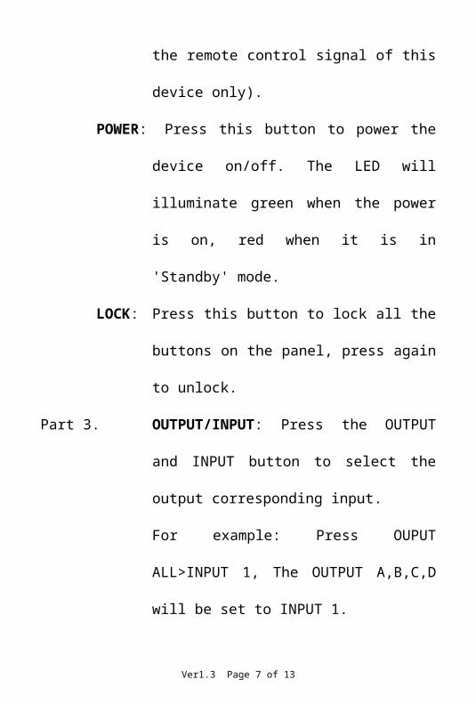
Part 2. IR: IR Receiver window (accepts the remote control signal of this device only).
POWER: Press this button to power the device on/off. The LED will illuminate green when the power is on, red when it is in 'Standby' mode.
LOCK: Press this button to lock all the buttons on the panel, press again to unlock.
Part 3. OUTPUT/INPUT: Press the OUTPUT and INPUT button to select the output corresponding input.For example: Press OUPUT ALL>INPUT 1, The OUTPUT A,B,C,D will be set to INPUT 1.
Part 4. Picture adjust:Press the button to adjust the output picture.For example:Press output 1>SCALER, The output 1 video will be scaler adjust.
Ver1.3 Page 3 of 13
Note: 1. Scaler adjust the step: six steps.2. The AUTO ADJUST button only work on VGA input.
Part 5. Sources input select: Press the button to select source input. For example:Press input 1>VGA,The input 1 will be select the VGA video input.
Part 6. EDID: Smart EDID management,the LCM will display the EDID operation.Press the MENU button will enter the EDID management window, press UP or DOWN button to select the needed EDID settting, press ENTER button to select the download input source.it can easy download any EDID mode to any input source.
Note: The EDID mode tableEDID Mode EDID Description1 1080i, 2CH AUDIO2 1080p, 2CH AUDIO3 DVI 1920X1080
EDID. What is it and what is it used for?Under normal circumstances, a source device (digital and analog) will require information about a connected device/display to assess what resolutions and features are available. The source can then cater its output to send only resolutions and features that are compatible with the attached device/display. This information is called EDID (Extended Display Information Data) and a source device can only accept and read one EDID from a connected device/display. Likewise, the source an only output one resolution for use by a connected device/display.Why is EDID so important with the HDMI Matrix ?The Matrix is complex piece of technology that replicates and
Ver1.3 Page 4 of 13
switches between multiple inputs and outputs. Each connected source device will require one EDID to read. EDID management is carefully handled by HDMI Matrix to provide a single EDID for each source to read.What options do I have to manage the EDID in the HDMI Matrix ?First, it is important to note that each source device can only output one video/audio signal type. This includes resolutions and timings. When multiple devices/displays are used, such as with the HDMI Matrix, it is important to use devices/displays that have similar or compatible resolutions/features. This will ensure that the single video/audio signal produced by the source device is accepted by all of the connected output devices/displays.The user has the option, through the EDID management window, to choose how the unit will manage the EDID from multiple HDMI devices/displays. Therefore the user has some control over the resolutions/features that the source devices will output. The HDMI Matrix for has a multiple EDID management modes that will control how the EDID information from multiple devices/displays are combined, ignored, and routed.
5.2 Rear Panel
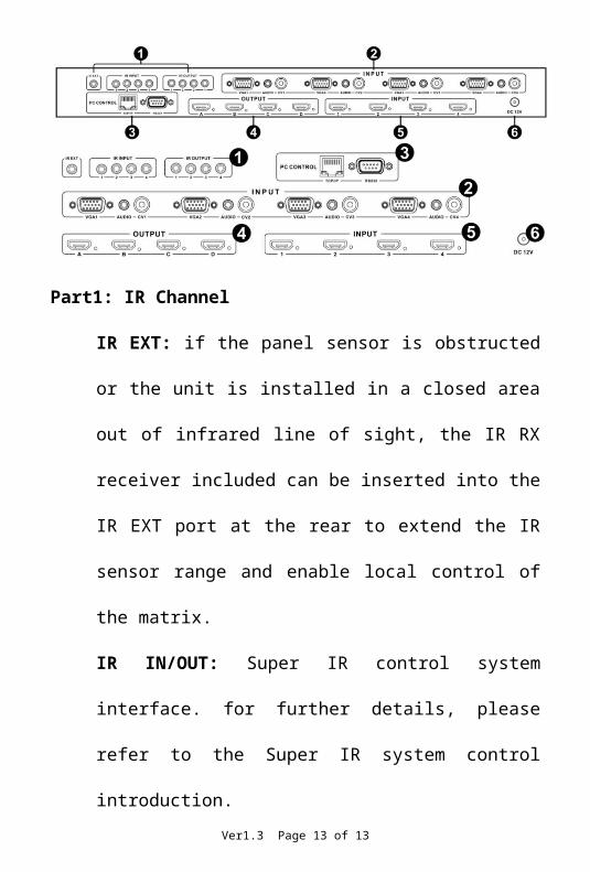
Part1: IR ChannelIR EXT: if the panel sensor is obstructed or the unit is installed in a closed area out of infrared line of sight, the IR RX receiver
Ver1.3 Page 5 of 13

included can be inserted into the IR EXT port at the rear to extend the IR sensor range and enable local control of the matrix.IR IN/OUT: Super IR control system interface. for further details, please refer to the Super IR system control introduction.
Part2: VGA CV AND AUDIO INPUTConnect to the VGA or CV input source devices such as a DVD player, a Set-top Box or PC with VGA cable or RCA coaxial cable.Each VGA or CV input is accompanied with a 3.5mm stereo audio input.
Part 3: PC CONTROLTCP/IP: This port is the link for TCP/IP controls, connect to an active Ethernet link with an RJ45 terminated cable.RS232: Connect to a PC or control system with D-Sub 9-pin cable for the transmission of RS-232 commands.
Part4: OUTPUTThe HDMI OUTPUT connect to HDMI equipped TVs.
Part5: HDMI INPUTConnect to the HDMI input source devices such as a DVD player or a Set-top Box with HDMI cable.
Part6: DC POWER INPUTPlug the 12V/2.5A DC power supply into the DC12V power in.
6. Remote Control(1). Press this button to power on the matrix or set it to standby mode.(2).Output selection.Letters correspond with the outputs on the matrix.(3).Input selection.Numbers correspond with the inputs on the matrix.
(4).Sources input selection.Press the button to select source
Ver1.3 Page 6 of 13
input. For example:Press input 1>VGA,The input 1 will be select the VGA video input.
(5).Picture adjust.Press the button to adjust the output picture.For example:Press output 1>SCALER,The output 1 video will be scaler adjust.Note: The AUTO ADJUST button only work on VGA input.
7. IR Control system
At Matrix end: Insert the 3.5mm jacks of the IR TX Emitters included with the unit into the IR TX Emitter ports at the rear of the matrix according to input. The IR signal is added to the HDMI of the input device so, for example, if the user is watching Blu-ray on input 1, the IR signal will be directed through the IR TX1 socket to control the device.
As each IR TX port is allocated to an individual HDMI input port, if the user is unable to establish IR control of the device, care should be taken to check firstly, that the IR emitter and HDMI input ports match (Input 1-TX1, Input2-TX2 etc.) with plugs secured in correct ports, and secondly, that the IR TX emitter sensors are firmly attached directly to the front of inputs and covering infrared sensor windows of the source devices.Some later adjustment may be needed to the location of the sensor to achieve the best performance results - sometimes moving the sensor to different areas on the source can improve IR performance.
NOTE: Infrared receiving areas of devices can be located by shining a flashlight onto the front of the device – the sensor should be able to be seen through the plastic as a small, round object inside.Insert 3.5mm jacks of IR RX receivers into RX ports, making sure the
Ver1.3 Page 7 of 13

receivers themselves are placed in clear view to receive an infrared signal from the remote handset used to control the display outputs.
Ver1.3 Page 8 of 13

9. PC controller user guideInstallationMatrix controller is a green software. Just copy MatrixController.exe to PC which is used to control the Matrix by RS232 COM port or TCP/IP to complete installation.Preparation Connect PC and Matrix by RS232 cable (headers of both sides
of cable should be FEMALE) or TCP/IP(local area network) Power-up Matrix Double click MatirxController.exe icon to run it
How to control Matrix “General” page
1. Select RS232 COM or TCP mode2. Select RS232 COM port3. Click to connect or disconnect PC and Matrix4. Select Matrix IP
Ver1.3 Page 9 of 13
5. Connect to Matrix IP6. Search Matrix IP7. Configure Matrix IP and MAC8. Click to reset to the factory settings9. Click to button system into the matrix mode10. Click to button system into the Multi-viewer mode; for details,
please refer to the Multi-viewer mode.11. Click to button system into the video wall mode; for details,
please refer to the video wall mode.12. Click to button select one input image zoom in four times to the
outputs. 13. Enable or disable Beep Configure TCP
After action of 7 , edit form will pop-up as below:
1. Select auto or static IP2. Rewrite the Matrix IP3. Rewrite the Matrix MAC
Ver1.3 Page 10 of 13
The Multi-viewer modeThe Multi-viewer mode has a variety of display modes. All the display modes as below:Detailed operations: While the PC software is running normally, click
on the button , via the mode of the drop-down box
choose 1/2/3/4 mode, and via the audio of the drop-
down box choose 1/2/3/4 input audio.
Picture outside Picture (POP) DisplayingMode 1:
Ver1.3 Page 11 of 13
Mode 2:
Mode 3:
Picture in Picture (PIP) DisplayingMode 4:
Ver1.3 Page 12 of 13
The video wall modeDetailed operations: While the PC software is running normally, click
on the button .
In this area, users can set the bezel size of the adjacent images in zoom-in model, to make the whole image looks coherently. As
shown in: .Figure 1 and Figure 2 will show you the difference between the original image and the image adjusted.
Figure 1 The Original Image
Figure 2 The Image AdjustedVer1.3 Page 13 of 13
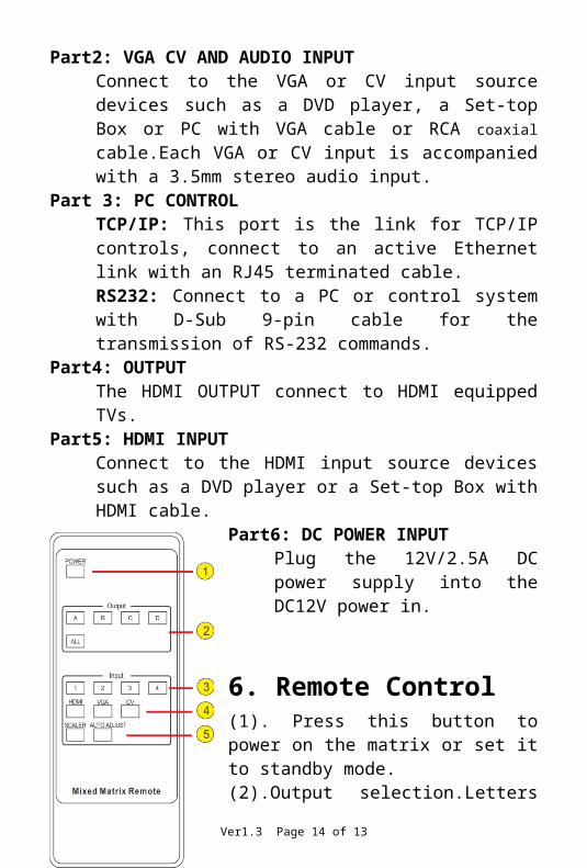
Diagram of Video Wall Displaying4x Zoom-in: It means matrix switcher is able to zoom in the input image and spilt to 4 parts, and then full-screen display on the output displayers one to one.
“EDID control” pag
Ver1.3 Page 14 of 13

1. Select the needed EDID to input port and click set button the EDID will write to the selected HDMI input ports.
“Matrix” page
1. LED which display Input number for respective Output2. Click to select Input port for respective Output port3. Click to select previous or next Input port for respective Output
port4. Click to select the seamless switching output mode5. Click to select the seamless switching time6. Click to automatically adjust the output picture7. Click to scaler the output picture8. Click to select the input signal sourceNote: The signal source for the VGA input 6 can use.
“FW upgrade” page
Ver1.3 Page 15 of 13
1. Click to open FW file(file extension is “.fw”)2. Display the FW file path3. Displaying the progress of the software upgrade4. Click to upgrade the Matrix software5. Display the message of the software upgrade6. Clear the message of the software upgradeNote: The matrix after software upgrade required again to power supply.
Ver1.3 Page 16 of 13

10. Connection and Installation
1. Connect up to 4 sources such as a Blu-Ray Player, game console, A/V Receiver, Cable or Satellite Receiver, etc. to the HDMI ,VGA or CV inputs on the unit. Insert and extract cables carefully with the power switch off. Connecting and disconnecting while the unit is powered can result in damage to circuitry.
2. Connect up to four HD displays using the output ports(A-D) on the matrix.
3. OPTIONAL:Connect the IR receiving extender to the IR EXT port on the matrix.
4. OPTIONAL:Connect an Ethernet cable from the TCP/IP port on the matrix to a local Area Network.
5. OPTIONAL:Connect an RS-232 cable from the RS232 port on the matrix.
6. OPTIONAL:Connect the IR receiving extender to the IR INPUT port and the IR emission extender to the IR output port on the matrix.
7. Connect the DC 12V Locking power supply to the power receptacle on the matrix.
8. Connect the power supply to an available electrical outlet.Ver1.3 Page 17 of 13