hc900 process control designer · about this document abstract the "process control...
TRANSCRIPT

Honeywell Process Solutions
HC900 Process Control Designer Function Block Reference Guide
Doc. No.51-52-25-109
Revision: 26 Revision Date: November 2019

ii ControlEdge HC900 Process Control Designer Function Block Reference Guide Revision 26 November 2019
Notices and Trademarks
Copyright 2019 by Honeywell Revision 26, November 2019
WARRANTY/REMEDY Honeywell warrants goods of its manufacture as being free of defective materials and faulty workmanship. Contact your local sales office for warranty information. If warranted goods are returned to Honeywell during the period of coverage, Honeywell will repair or replace without charge those items it finds defective. The foregoing is Buyer's sole remedy and is in lieu of all other warranties, expressed or implied, including those of merchantability and fitness for a particular purpose. Specifications may change without notice. The information we supply is believed to be accurate and reliable as of this printing. However, we assume no responsibility for its use.
While we provide application assistance personally, through our literature and the Honeywell web site, it is up to the customer to determine the suitability of the product in the application.
Honeywell Process Solutions
1250 W Sam Houston Pkwy S
Houston, TX 77042
ControlEdge HC900 is a U.S. trademark of Honeywell
Other brand or product names are trademarks of their respective owners.
Revision 26 ControlEdge HC900 Process Control Designer Function Block Reference Guide iii November 2019
About This Document
Abstract The "Process Control Designer" configuration software program is used for ControlEdge HC900 Controller and Operator Interface configuration and operates on a PC with WindowsTM 7, 8 and 10. The software program uses graphic symbols and line drawing connections to create custom control strategies. Menus are provided in the software to allow selection of screens for the operator interface and to customize screen access methods and operator keys. Completed configurations are loaded into the control system using a dedicated communication port in the controller.
References The following list identifies all documents that may be sources of reference for material discussed in this publication.
Document Title Doc ID
ControlEdge HC900 Controller Technical Overview 51-52-03-31
Legacy ControlEdge HC900 Controller Installation and User Guide
51-52-25-107
ControlEdge HC900 Operator Interface User Guide 51-52-25-108
ControlEdge HC900 Control Designer User Guide 51-52-25- 110
ControlEdge HC900 Control Communications User Guide 51-52-25-111
900 Control Station For use with ControlEdge HC900 51-52-25-148
Revision History The following list provides notes concerning all revisions of this document.
51-52-25-109 (this document) Revision details
April 2018, Rev. 23 R650 updates including Universal IO and name change
December 2018, Rev 24 Addition of Eight Min-Max-Average-Sum block (8MMA)
March 2019, Rev 25
May 2019, Rev 25
Updated Analog Input Voting section
Added ‘Warning’ under “TPSC (3POS) Function Block” section
Added “(ASCII characters only)” in the place of “16 character length”.
November 2019, Rev 26 Added Redundant Universal IO Function Blocks.

iv ControlEdge HC900 Process Control Designer Function Block Reference Guide Revision 26 November 2019
Contact Information For Europe, Asia Pacific, North and South America contact details, refer to the back page of this manual or the appropriate Honeywell Solution Support web site:
Honeywell Organization WWW Address (URL)
Corporate http://www.honeywell.com
Honeywell Process Solutions http://hpsweb.honeywell.com/ps
HPS Technical tips http://content.honeywell.com/ipc/faq
Telephone and Email Contacts
Area Organization Phone Number
United States and Canada
Honeywell Inc. 1-800-343-0228 Customer Service
1-800-423-9883 Global Technical Support
Global Email Support
Honeywell Process Solutions
Email: (Sales)
or (TAC)

Revision 26 ControlEdge HC900 Process Control Designer Function Block Reference Guide v November 2019
Symbol Definitions The following table lists those symbols that may be used in this document to denote certain conditions.
Symbol Definition
This DANGER symbol indicates an imminently hazardous situation, which, if not avoided, will result in death or serious injury.
This WARNING symbol indicates a potentially hazardous situation, which, if not avoided, could result in death or serious injury.
This CAUTION symbol may be present on Control Product instrumentation and literature. If present on a product, the user must consult the appropriate part of the accompanying product literature for more information.
This CAUTION symbol indicates a potentially hazardous situation, which, if not avoided, may result in property damage.
WARNING PERSONAL INJURY: Risk of electrical shock. This symbol warns the user of a potential shock hazard where HAZARDOUS LIVE voltages greater than 30 Vrms, 42.4 Vpeak, or 60 Vdc may be accessible. Failure to comply with these instructions could result in death or serious injury.
ATTENTION, Electrostatic Discharge (ESD) hazards. Observe precautions for handling electrostatic sensitive devices
Protective Earth (PE) terminal. Provided for connection of the protective earth (green or green/yellow) supply system conductor.
Functional earth terminal. Used for non-safety purposes such as noise immunity improvement. NOTE: This connection shall be bonded to protective earth at the source of supply in accordance with national local electrical code requirements.
Earth Ground. Functional earth connection. NOTE: This connection shall be bonded to Protective earth at the source of supply in accordance with national and local electrical code requirements.
Chassis Ground. Identifies a connection to the chassis or frame of the equipment shall be bonded to Protective Earth at the source of supply in accordance with national and local electrical code requirements.
vi ControlEdge HC900 Process Control Designer Function Block Reference Guide Revision 26 November 2019
Table of Contents
Notices and Trademarks .................................................................................................. ii
About This Document ...................................................................................................... iii Abstract .................................................................................................................................................................... iii
References ............................................................................................................................................................... iii
Revision History ...................................................................................................................................................... iii
Contact Information ..................................................................................................................................................iv
Symbol Definitions .................................................................................................................................................... v
Table of Contents ............................................................................................................ vi Tables ..................................................................................................................................................................... xii
Figures ..................................................................................................................................................................... xv
Introduction ..................................................................................................................... 1 Overview ................................................................................................................................................................... 1
Accessing function block properties .......................................................................................................................... 1
Normal Scan vs. Fast Scan Function Blocks ............................................................................................................. 2
Block Order ............................................................................................................................................................... 2
Function Blocks ............................................................................................................... 3 Introduction ............................................................................................................................................................... 3
Function block listings ............................................................................................................................................... 3
ABS Absolute Value Function Block ...................................................................................................................... 13
ADD Function Block ............................................................................................................................................... 15
4ADD Function Block ............................................................................................................................................. 16
AGA8DL Function Block ........................................................................................................................................ 17
AGA8GS Function Block ........................................................................................................................................ 26
AGA3O Function Block .......................................................................................................................................... 32
AGA7TM Function Block ....................................................................................................................................... 37
AGA9UM Function Block ...................................................................................................................................... 41
AI Function Block ................................................................................................................................................... 45

Revision 26 ControlEdge HC900 Process Control Designer Function Block Reference Guide vii November 2019
Analog Input Voting ................................................................................................................................................ 51
ALMGR Alarm Group Function Block ................................................................................................................... 61
ALT Alternator Function Block .............................................................................................................................. 63
AMB Auto/Manual Bias Function Block ................................................................................................................ 72
ANAIMP Safety Analog Import Function Block .................................................................................................... 78
2AND Function Block ............................................................................................................................................. 83
4ALM Function Block ............................................................................................................................................. 85
4AND Function Block ............................................................................................................................................. 87
8AND Function Block ............................................................................................................................................. 89
AO Function Block .................................................................................................................................................. 91
Analog Output Validated ......................................................................................................................................... 94
ASYS Analog System Status Function Block ......................................................................................................... 99
BCD Function Block ............................................................................................................................................. 102
BOOL Boolean Logic Function Block .................................................................................................................. 104
CASTA Configuration Access Status .................................................................................................................... 107
CALEVT Calendar Event Function Block ............................................................................................................ 110
CARB Carbon Potential Function Block ............................................................................................................... 118
CAVG Continuous Average Function Block ........................................................................................................ 136
CMPR Comparison Calculation Function Block ................................................................................................... 139
DC Device Control Function Block ....................................................................................................................... 140
DCMP Deviation Compare Function Block .......................................................................................................... 145
DDEC Digital Decoder Function Block ................................................................................................................ 147
DENC Digital Encoder Function Block ................................................................................................................ 149
DEWP Function Block .......................................................................................................................................... 151
DI Function Block ................................................................................................................................................. 154
DIGIMP Safety Digital Import Function Block .................................................................................................... 157
Digital Input Voting ............................................................................................................................................... 161
8DI Function Block ............................................................................................................................................... 165
DIV Function Block .............................................................................................................................................. 168
DLAY Function Block .......................................................................................................................................... 170
DO Function Block ................................................................................................................................................ 172
Digital Output Validated........................................................................................................................................ 175
DSW Digital Switch Function Block ..................................................................................................................... 182
viii ControlEdge HC900 Process Control Designer Function Block Reference Guide Revision 26 November 2019
ENTH Humidity and Enthalpy Function Block ..................................................................................................... 183
FGEN Function Generator Function Block ........................................................................................................... 185
FI Frequency Input ................................................................................................................................................ 189
FMON Fault Monitor Function Block ................................................................................................................... 193
FRCP Force Present Function Block ..................................................................................................................... 196
FSS Four Selector Switch Function Block ............................................................................................................ 198
FSYS Fast Logic System Monitor ......................................................................................................................... 201
HLLM High Low Limiter Function Block ............................................................................................................ 203
HMON High Monitor Function Block .................................................................................................................. 205
HOA Hand/Off/Auto Switch Function Block ........................................................................................................ 207
HSEL High Selector Function Block ..................................................................................................................... 212
IMM - IO Module Monitor Block ......................................................................................................................... 214
LDLG Lead/Lag Function Block ........................................................................................................................... 216
LMON Low Monitor Function Block ................................................................................................................... 219
LPSW Loop Switch Function Block ..................................................................................................................... 221
LSEL Low Selector Function Block ...................................................................................................................... 223
LTCH Latch Function Block ................................................................................................................................. 224
MATH Function Block .......................................................................................................................................... 226
Multiple Alarm with Hysteresis ............................................................................................................................. 230
STK Stack light ..................................................................................................................................................... 234
MBR Modbus Read Function Block ..................................................................................................................... 236
MBS Modbus Slave Function Block ..................................................................................................................... 240
MBW Modbus Write Function Block ................................................................................................................... 250
MDSW Mode Switch Function Block ................................................................................................................... 254
MDFL Mode Flag Function Block ........................................................................................................................ 256
MMA Min/Max/Avg Function Block .................................................................................................................... 258
MUL Multiplier Function Block............................................................................................................................ 267
4MUL Multiplier (4 input) Function Block ........................................................................................................... 269
NEG Negate Function Block ................................................................................................................................. 271
NOT Function Block ............................................................................................................................................. 272
ONDT On Delay Timer Function Block ............................................................................................................... 273
OFDT Off Delay Timer Function Block ............................................................................................................... 276
ON/OFF Function Block ....................................................................................................................................... 278

Revision 26 ControlEdge HC900 Process Control Designer Function Block Reference Guide ix November 2019
2OR Function Block .............................................................................................................................................. 287
4OR Function Block .............................................................................................................................................. 289
8OR Function Block .............................................................................................................................................. 291
PB Pushbutton Function Block .............................................................................................................................. 294
PDE Peer Data Exchange Function Block ............................................................................................................. 297
PDR Peer Data Read Function Block .................................................................................................................... 302
PDW Peer Data Write Function Block .................................................................................................................. 304
PI Pulse Input......................................................................................................................................................... 306
POUT Pulse Output ............................................................................................................................................... 309
PID Function Block ............................................................................................................................................... 312
PPO Position Proportional Output Function Block ............................................................................................... 335
PSYC Psychrometric Calculations Function Block ............................................................................................... 340
PTMR Periodic Timer Function Block .................................................................................................................. 342
QDT Quadrature Function Block .......................................................................................................................... 345
RAI Function Block ............................................................................................................................................... 348
RACK Function Block .......................................................................................................................................... 353
RAMP Function Block .......................................................................................................................................... 355
RCON Read Constant Function Block .................................................................................................................. 362
RCP Recipe Selector Function Block .................................................................................................................... 364
RH Relative Humidity Function Block.................................................................................................................. 366
ROC Rate of Change Function Block .................................................................................................................... 368
RSTAT Redundancy Status Function Block ......................................................................................................... 371
RSW Rotary Switch Function Block ..................................................................................................................... 372
RTC Real Time Clock Function Block .................................................................................................................. 374
RTMR Resettable Timer Function Block .............................................................................................................. 375
RUIO-AI Function Block ...................................................................................................................................... 378
RUIO-AO Function Block ..................................................................................................................................... 382
RUIO-DI Function Block ...................................................................................................................................... 386
RUIO-DO Function Block ..................................................................................................................................... 388
SAFPDE Safety Peer Monitor Function Block ..................................................................................................... 391
SCB Scale and Bias Function Block ...................................................................................................................... 395
SEQ Sequencer Function Block ............................................................................................................................ 397
SPEV Setpoint Programming Event Decoder Function Block .............................................................................. 403

x ControlEdge HC900 Process Control Designer Function Block Reference Guide Revision 26 November 2019
SPP Function Block ............................................................................................................................................... 406
SPS Setpoint Scheduler Function Block ................................................................................................................ 418
SPSA Setpoint Scheduler Auxiliary Setpoint Function Block .............................................................................. 425
SQRT Function Block ........................................................................................................................................... 426
STG Stage Function Block .................................................................................................................................... 428
STFL Setpoint Scheduler Stage Flags Function Block .......................................................................................... 435
STRIG Selectable Trigger Function Block ............................................................................................................ 436
STSW Setpoint Scheduler State Switch Function Block ....................................................................................... 438
SUB Subtraction Function Block .......................................................................................................................... 439
4SUB Function Block ............................................................................................................................................ 440
SW Analog Switch Function Block ....................................................................................................................... 441
SYNC Function Block ........................................................................................................................................... 443
TAHD Track and Hold Function Block................................................................................................................. 445
TCPR Function Block ........................................................................................................................................... 447
TCPS Function Block ............................................................................................................................................ 451
TCPW Function Block .......................................................................................................................................... 459
TGFF Toggle Flip Flop Function Block ................................................................................................................ 463
TMDT Time and Date Function Block .................................................................................................................. 465
TOT Totalizer Function Block .............................................................................................................................. 466
TPO Time Proportional Output Function Block .................................................................................................... 469
TPSC (3POS) Function Block ............................................................................................................................... 472
TRIG Trigger Function Block ............................................................................................................................... 487
TRND Trend Rate Function Block ........................................................................................................................ 489
TRPT Trend Point Function Block ........................................................................................................................ 491
UIO-AI Function Block ......................................................................................................................................... 494
UIO-AO Function Block ....................................................................................................................................... 498
UIO-DI Function Block ......................................................................................................................................... 502
UIO-DO Function Block ....................................................................................................................................... 505
UPDN Up/Down Function Block .......................................................................................................................... 508
VLIM Velocity Limiter Function Block ................................................................................................................ 510
WCON Write Constant Function Block ................................................................................................................ 512
WTUN Write Tuning Constants Function Block .................................................................................................. 514
WVAR Write Variable Function Block ................................................................................................................. 516

Revision 26 ControlEdge HC900 Process Control Designer Function Block Reference Guide xi November 2019
XFR Bumpless Analog Transfer Switch Function Block ...................................................................................... 518
XOR Function Block ............................................................................................................................................. 520
5XYRB Function Block ........................................................................................................................................ 521
5XYRT Function Block ......................................................................................................................................... 525
6XYRT Function Block ......................................................................................................................................... 528
6XYRWG .............................................................................................................................................................. 533

xii ControlEdge HC900 Process Control Designer Function Block Reference Guide Revision 26 November 2019
Tables Table 1 Function blocks by category ............................................................................................................................ 3 Table 2 Function blocks alphabetically ......................................................................................................................... 8 Table 3 AGA8DL General tab configuration parameters ........................................................................................... 19 Table 4 AGA8DL Detail tab configuration parameters .............................................................................................. 20 Table 5 AGA Error Codes .......................................................................................................................................... 22 Table 6 AGA8GS General tab configuration parameters ........................................................................................... 27 Table 7 AGA8GS Detail tab configuration parameters .............................................................................................. 28 Table 8 AGA3O Orifice tab configuration parameters ............................................................................................... 33 Table 9 AGA3O Flow Rates tab configuration parameters ........................................................................................ 35 Table 10 AGA7TM Turbine tab configuration parameters ........................................................................................ 38 Table 11 AGA7TM Flow Rates tab configuration parameters ................................................................................... 39 Table 12 AGA9UM Ultrasonic tab configuration parameters .................................................................................... 42 Table 13 AGA9UM Flow Rates tab configuration parameters .................................................................................. 43 Table 14 Analog Input configuration parameters ....................................................................................................... 46 Table 15 ControlEdge HC900 Input Types and Ranges ............................................................................................. 48 Table 16 Analog alarm configuration parameters ...................................................................................................... 59 Table 17 ALT general tab parameters ........................................................................................................................ 67 Table 18 ALT sequence tab parameters ..................................................................................................................... 70 Table 19 AMB General tab configuration parameters ................................................................................................ 73 Table 20 AMB Start Restart tab configuration parameters .......................................................................................... 74 Table 21 AMB Range/limit tab configuration parameters ........................................................................................... 75 Table 22 AMB Alarm tab configuration parameters ................................................................................................... 76 Table 23 Analog output configuration parameters ..................................................................................................... 92 Table 24 Analog system status block outputs ........................................................................................................... 100 Table 25 BOOL function block configuration parameters ....................................................................................... 106 Table 26 Pin details of CASTA function block ......................................................................................................... 108 Table 27 Calendar Event Details tab configuration parameters ................................................................................ 112 Table 28 Calendar Event Special Days tab configuration parameters ...................................................................... 114 Table 29 Calendar Event Setpoint tab configuration parameters .............................................................................. 116 Table 30 CARB General tab configuration parameters ............................................................................................ 121 Table 31 CARB Start/Restart tab configuration parameter ....................................................................................... 122 Table 32 CARB RSP tab configuration parameters................................................................................................... 124 Table 33 CARB Range/limit tab configuration parameters ....................................................................................... 126 Table 34 CARB Tuning tab configuration parameters .............................................................................................. 127 Table 35 CARB Accutune III tab configuration parameters ..................................................................................... 129 Table 36 CARB Alarms tab configuration parameters .............................................................................................. 132 Table 37 Carbon Potential tab configuration parameters .......................................................................................... 133 Table 38 Continuous average configuration parameters ........................................................................................... 137 Table 39 Monitored events and device states ........................................................................................................... 142 Table 40 Device control function block parameters ................................................................................................. 143 Table 41 DCMP configuration parameters ............................................................................................................... 146 Table 42 Dewpoint function block parameters ......................................................................................................... 152 Table 43 Digital input configuration parameters ...................................................................................................... 155 Table 44 Eight Digital input configuration parameters ............................................................................................ 166 Table 45 On Delay/Off Delay configuration parameters .......................................................................................... 171 Table 46 Digital output configuration parameters .................................................................................................... 173 Table 47 Eight Digital output configuration parameters .......................................................................................... 180 Table 48 Function generator configuration parameters ............................................................................................ 186 Table 49 Frequency Input configuration parameters ................................................................................................ 191 Table 50 Force Present configuration parameters .................................................................................................... 197 Table 51 Four Selector Switch (FSS) configuration parameters for operator interface display ............................... 199 Table 52 Fast logic system status block outputs ....................................................................................................... 202 Table 53 High low limit configuration parameters ................................................................................................... 204

Revision 26 ControlEdge HC900 Process Control Designer Function Block Reference Guide xiii November 2019
Table 54 High monitor function block configuration parameters ............................................................................. 206 Table 55 HOA general tab parameters ..................................................................................................................... 208 Table 56 HOA feedback signal tab parameters ........................................................................................................ 209 Table 57 Lead lag configuration parameters ............................................................................................................ 217 Table 58 Low monitor function block configuration parameters ............................................................................. 220 Table 59 Math function block configuration parameters .......................................................................................... 228 Table 60 MALM function block configuration parameters ...................................................................................... 233 Table 61 MBR function block configuration parameters ......................................................................................... 237 Table 62 MBS Block General tab configuration parameters .................................................................................... 243 Table 63 MBS Block Read tab configuration parameters ......................................................................................... 245 Table 64 MBS Block Write tab configuration parameters ........................................................................................ 247 Table 65 MBW function block configuration parameters ........................................................................................ 251 Table 66 Min/Max/Ave/Sum function block configuration parameters ................................................................... 260 Table 67 Mass flow function block configuration parameters.................................................................................. 265 Table 68 On delay timer function block example ..................................................................................................... 274 Table 69 Off delay timer configuration parameters .................................................................................................. 277 Table 70 ON/OFF General tab configuration parameters .......................................................................................... 280 Table 71 ON/OFF Start/Restart tab configuration parameter .................................................................................... 282 Table 72 ON/OFF RSP tab configuration parameters ............................................................................................... 283 Table 73 ON/OFF Range/limit tab configuration parameters.................................................................................... 284 Table 74 ON/OFF Alarm tab configuration parameters ........................................................................................... 285 Table 75 Pushbutton function group configuration .................................................................................................. 295 Table 76 PDE General tab configuration parameters ............................................................................................... 299 Table 77 PDE Read tab configuration parameters .................................................................................................... 299 Table 78 PDE Write tab configuration parameters ................................................................................................... 300 Table 79 Pulse Input Configuration Parameters ........................................................................................................ 307 Table 80 Pulse Output Configuration Parameters ..................................................................................................... 310 Table 81 PID General tab configuration parameters ................................................................................................ 316 Table 82 PID Start/Restart tab configuration parameter ........................................................................................... 317 Table 83 PID RSP tab configuration parameters ...................................................................................................... 319 Table 84 PID Range/limit tab configuration parameters .......................................................................................... 321 Table 85 PID Tuning tab configuration parameters.................................................................................................. 323 Table 86 PID Accutune III tab configuration parameters ......................................................................................... 324 Table 87 PID Alarms tab configuration parameters ................................................................................................. 328 Table 88 Position Proportional Motor Control .......................................................................................................... 337 Table 89 PSYC function block configuration parameters ........................................................................................ 341 Table 90 PT function block configuration parameters .............................................................................................. 343 Table 91 QDT parameters ........................................................................................................................................ 346 Table 92 Analog Input with Remote C/J configuration parameters ......................................................................... 349 Table 93 ControlEdge HC900 Input Types and Ranges for RAI Function Block .................................................... 351 Table 94 RAMP general tab parameters ................................................................................................................... 359 Table 95 RAMP tabs parameters .............................................................................................................................. 360 Table 96 Read constant configuration data ............................................................................................................... 363 Table 97 Metric units ................................................................................................................................................ 367 Table 98 ROC configuration parameters .................................................................................................................. 369 Table 99 Redundancy Status configuration parameters ............................................................................................ 371 Table 100 RTMR configuration parameters ............................................................................................................. 376 Table 101 RUIO-AI configuration parameters ......................................................................................................... 379 Table 102 Analog output configuration parameters ................................................................................................. 384 Table 103 RUIO Digital input configuration parameters ......................................................................................... 387 Table 104: Configurable Parameters RUIO DO ........................................................................................................ 389 Table 105 SCB configuration parameters ................................................................................................................. 396 Table 106 SPP inputs and current state .................................................................................................................... 410 Table 107 Restart scenario options ........................................................................................................................... 411 Table 108 SPP configuration parameters .................................................................................................................. 412

xiv ControlEdge HC900 Process Control Designer Function Block Reference Guide Revision 26 November 2019
Table 109 Tag/Failsafe configuration parameters .................................................................................................... 420 Table 110 Main Output labels configuration parameters .......................................................................................... 421 Table 111 Auxiliary Output labels configuration parameters ................................................................................... 422 Table 112 Event labels configuration parameters ..................................................................................................... 423 Table 113 SQRT configuration parameters .............................................................................................................. 427 Table 114 STG general tab parameters ..................................................................................................................... 430 Table 115 Default PV sources and compare type operators ..................................................................................... 432 Table 116 STG Stage Tabs parameters ..................................................................................................................... 433 Table 117 TCPR function block configuration parameters ...................................................................................... 448 Table 118 TCPS Block General tab configuration parameters ................................................................................. 452 Table 119 TCPS Block Read tab configuration parameters ...................................................................................... 454 Table 120 TCPS Block Write tab configuration parameters ..................................................................................... 457 Table 121 TCPW function block configuration parameters ..................................................................................... 460 Table 122 Time and Date configuration parameters ................................................................................................. 465 Table 123 TOT configuration parameters................................................................................................................. 467 Table 124 TPO configuration parameters ................................................................................................................. 471 Table 125 TPSC General tab configuration parameters ........................................................................................... 474 Table 126 TPSC Start/Restart tab configuration parameter ....................................................................................... 476 Table 127 TPSC RSP tab configuration parameters .................................................................................................. 477 Table 128 TPSC Range/limit tab configuration parameters ...................................................................................... 479 Table 129 TPSC Tuning tab configuration parameters ............................................................................................. 481 Table 130 TPSC Accutune tab configuration parameters .......................................................................................... 482 Table 131 TPSC Alarms tab configuration parameters ............................................................................................. 484 Table 132 TPSC Motor tab configuration parameters ............................................................................................... 486 Table 133 TRND block configuration parameters .................................................................................................... 490 Table 134 UIO-AI configuration parameters ............................................................................................................ 495 Table 135 Analog output configuration parameters ................................................................................................. 500 Table 136 UIO Digital input configuration parameters ............................................................................................ 503 Table 137: Configurable Parameters UIO DO ........................................................................................................... 506 Table 138 Up/down configuration parameters ......................................................................................................... 509 Table 139 VLIM Configuration Parameters ............................................................................................................. 511 Table 140 XFR switch configuration data ................................................................................................................ 519

Revision 26 ControlEdge HC900 Process Control Designer Function Block Reference Guide xv November 2019
Figures Figure 1 ABS function block example ....................................................................................................................... 14 Figure 2 ADD function block example ....................................................................................................................... 15 Figure 3 4ADD function block example ..................................................................................................................... 16 Figure 4 AGA8DL function block example ............................................................................................................... 25 Figure 5 AGA8GS function block example ............................................................................................................... 31 Figure 6 AGA3O function block example .................................................................................................................. 36 Figure 7 AGA7TM function block example ............................................................................................................... 40 Figure 8 AGA9UM function block example .............................................................................................................. 44 Figure 9 AI function block example ........................................................................................................................... 50 Figure 10 - ALM Alarm Function Block ..................................................................................................................... 56 Figure 11 ALM function block example .................................................................................................................... 60 Figure 12 ALMGR Function Block Example .............................................................................................................. 62 Figure 13 ALT function block example ..................................................................................................................... 71 Figure 14 AMB function block example .................................................................................................................... 77 Figure 15 2AND function block example ................................................................................................................... 84 Figure 16 4ALM function block example ................................................................................................................... 86 Figure 17 4AND function block example ................................................................................................................... 88 Figure 18 8AND function block example ................................................................................................................... 90 Figure 19 AO function block example ....................................................................................................................... 93 Figure 20 BCD function block example ................................................................................................................... 103 Figure 21 BOOL function block example ................................................................................................................ 106 Figure 22 CALEVT function block example............................................................................................................ 117 Figure 23 CARB function block examples ............................................................................................................... 135 Figure 24 CAVG function block example ................................................................................................................ 138 Figure 25 CMPR function block example ................................................................................................................ 139 Figure 26 DC function block example ...................................................................................................................... 144 Figure 27 DCMP function block example ................................................................................................................ 146 Figure 28 DDEC function block example ................................................................................................................ 148 Figure 29 DENC function block example ................................................................................................................ 150 Figure 30 DEWP function block example ................................................................................................................ 153 Figure 31 Digital input function block example ....................................................................................................... 156 Figure 32 8Point DI function block example ............................................................................................................ 167 Figure 33 DIV function block example .................................................................................................................... 169 Figure 34 DO function block example ..................................................................................................................... 174 Figure 35 DO-V function block 8DO Function Block .............................................................................................. 178 Figure 36 8 Point DO function block example ......................................................................................................... 181 Figure 37 DSW function block example .................................................................................................................. 182 Figure 38 ENTH function block example .................................................................................................................. 184 Figure 39 FGEN function block example ................................................................................................................. 188 Figure 40 FI function block example ........................................................................................................................ 192 Figure 41 FSS function block example ..................................................................................................................... 200 Figure 42 HLLM function block example ................................................................................................................ 204 Figure 43 HMON function block example ............................................................................................................... 206 Figure 44 HOA function block example ................................................................................................................... 211 Figure 45 HSEL Function Block Example ............................................................................................................... 213 Figure 46 IMM function block .................................................................................................................................. 215 Figure 47 LDLG function block example ................................................................................................................. 218 Figure 48 LMON function block example................................................................................................................ 220 Figure 49 LPSW function block example ................................................................................................................. 222 Figure 50 LSEL function block example .................................................................................................................. 223 Figure 51 LTCH function block example ................................................................................................................. 225 Figure 52 MATH function block example................................................................................................................ 229

Table of Contents Figures
xvi ControlEdge HC900 Process Control Designer Function Block Reference Guide Revision 26 November 2019
Figure 53 MBR function block example .................................................................................................................. 239 Figure 54 MBS function block example ................................................................................................................... 249 Figure 55 MBW function block example ................................................................................................................. 253 Figure 56 MDSW function block example ............................................................................................................... 255 Figure 57 MDFL function block example ................................................................................................................ 257 Figure 58 MMA function block example ................................................................................................................. 260 Figure 59 MSF function block example ................................................................................................................... 266 Figure 60 MUL function block example .................................................................................................................. 268 Figure 61 4MUL function block example ................................................................................................................ 270 Figure 62 NEG function block example ................................................................................................................... 271 Figure 63 NOT function block example ................................................................................................................... 272 Figure 64 ONDT function block example ................................................................................................................ 275 Figure 65 OFDT function block example ................................................................................................................. 278 Figure 66 ON/OFF function block example ............................................................................................................. 286 Figure 67 2OR function block example .................................................................................................................... 288 Figure 68 4OR function block example .................................................................................................................... 290 Figure 69 8OR function block example .................................................................................................................... 293 Figure 70 PB function block example ...................................................................................................................... 296 Figure 71 PDE Function Block Example ................................................................................................................. 301 Figure 72 PI function block example ........................................................................................................................ 308 Figure 73 POUT function block example ................................................................................................................. 311 Figure 74 PID function block example ..................................................................................................................... 329 Figure 75 Duplex control example ........................................................................................................................... 330 Figure 76 Cascade control example .......................................................................................................................... 331 Figure 77 Ratio control example .............................................................................................................................. 332 Figure 78 Cascade control of a boiler drum level - basic ......................................................................................... 333 Figure 79 Cascade control of a boiler drum level - 3 element feedwater control ..................................................... 334 Figure 80 Position Proportional Motor Control ........................................................................................................ 339 Figure 81 PSYC function block example .................................................................................................................. 341 Figure 82 PT function block example ....................................................................................................................... 344 Figure 83 Quadrature function block example ......................................................................................................... 347 Figure 84 RAI function block example .................................................................................................................... 352 Figure 85 Rack Monitor function block example ..................................................................................................... 354 Figure 86 RAMP function block example ................................................................................................................ 361 Figure 87 RCON function block example ................................................................................................................ 363 Figure 88 RCP function block example .................................................................................................................... 365 Figure 89 RH function block example ...................................................................................................................... 367 Figure 90 ROC function block responses ................................................................................................................. 370 Figure 91 ROC function block example ................................................................................................................... 370 Figure 92 RSW function block example ................................................................................................................... 373 Figure 93 RTC function block example ................................................................................................................... 374 Figure 94 Timing diagram for resettable timer ......................................................................................................... 377 Figure 95 SAFPDE function block examples ........................................................................................................... 394 Figure 96 SCB function block examples .................................................................................................................. 396 Figure 97 Sequencer function block example - Part 1 .............................................................................................. 401 Figure 98 Sequencer function block example - Part 2 .............................................................................................. 401 Figure 99 Sequencer function block example - Part 3 .............................................................................................. 402 Figure 100 SPEV function block example................................................................................................................ 405 Figure 101 PID with setpoint programmer and guaranteed soak .............................................................................. 413 Figure 102 PID with setpoint programmer and event outputs .................................................................................. 414 Figure 103 Alternate methods for actuating SP programmer START/HOLD/RESET functions ............................. 415 Figure 104 Using the setpoint programmer AUX output ......................................................................................... 416 Figure 105 Controlled restart after power loss ......................................................................................................... 417 Figure 106 Setpoint scheduler function block suite .................................................................................................. 424

Table of Contents Figures
Revision 26 ControlEdge HC900 Process Control Designer Function Block Reference Guide xvii November 2019
Figure 107 SQRT function block example ............................................................................................................... 427 Figure 108 STG function block example .................................................................................................................. 434 Figure 109 STRIG function block example ............................................................................................................... 437 Figure 110 SUB function block example ................................................................................................................. 439 Figure 111 4SUB function block example................................................................................................................ 440 Figure 112 SW function block example ................................................................................................................... 442 Figure 113 SYNC function block example ............................................................................................................... 444 Figure 114 TAHD function block example .............................................................................................................. 446 Figure 115 TCPR function block example ............................................................................................................... 450 Figure 116 TCPS function block example ................................................................................................................ 458 Figure 117 TCPW function block example .............................................................................................................. 462 Figure 118 TGFF function block example................................................................................................................ 464 Figure 119 TOT function block examples ................................................................................................................ 468 Figure 120 TPO function block example .................................................................................................................. 471 Figure 121 TPSC function block example ................................................................................................................ 486 Figure 122 TRIG function block example ................................................................................................................ 488 Figure 123 TRPT Dialog to configure points by signal tag ....................................................................................... 492 Figure 124 TRPT Dialog to configure points by Modbus Address ........................................................................... 492 Figure 125 TRND and TRPT function block example ............................................................................................. 493 Figure 126 UIOAI function block example .............................................................................................................. 497 Figure 127 UIO-AO function block example ........................................................................................................... 501 Figure 128 UIODI function block example .............................................................................................................. 504 Figure 129 UIODO function block example ............................................................................................................ 507 Figure 130 UPDN function block example .............................................................................................................. 509 Figure 131 VLIM function block example ............................................................................................................... 511 Figure 132 WTUN function block example ............................................................................................................. 515 Figure 133 XFR function block example ................................................................................................................. 519 Figure 134 XOR function block example ................................................................................................................. 520 Figure 135 5XYRB function block example ............................................................................................................ 524 Figure 136 5XYRT function block example ............................................................................................................. 527 Figure 137 6XYRT function block example ............................................................................................................. 532 Figure 138 6XYRWG function block example ......................................................................................................... 535


Revision 26 ControlEdge HC900 Process Control Designer Function Block Reference Guide 1 November 2019
Introduction
Overview
Purpose of this section This Reference Guide presents detailed reference data for each function block. The reference data is organized in alphabetical order by the Function Block type identification label.
There is a list of Function Blocks grouped in categories as they appear on the Process Control Designer.
The presented data covers each control blocks
• function,
• inputs/outputs,
• point name,
• configuration parameters
• index numbers (used for reading [RCON] and writing [WCON] block parameter constants)
ATTENTION
Select the index number of the required parameter from the specific function block reference data and enter it in the appropriate field in the “Read Constant Properties” (RCON) or “Write Constant Properties” (WCON) dialog box.
• technical reference
• examples
Of course, data varies based on what is pertinent for each function block since they do not all have a point name or configuration parameters and do not all require technical reference information.
Reader assumptions It is assumed that you are familiar with the operation of the ControlEdge HC900 Control Designer and its help or its manual, ControlEdge HC900 Control Designer User's Guide (51-52-25-110).
Accessing function block properties Double click on the function block to access the function block properties dialog box.

Introduction Normal Scan vs. Fast Scan Function Blocks
2 ControlEdge HC900 Process Control Designer Function Block Reference Guide Revision 26 November 2019
Normal Scan vs. Fast Scan Function Blocks The Worksheet Toolbox in the HC Designer is a dockable window listing all function blocks. The name of the active configuration appears at the top of the window. Function blocks are categorized under Normal Scan and Fast Scan shown at tabs at bottom of window.
Click on either tab to display its available function blocks.
All function blocks are available under the Normal Scan tab. Normal Scan blocks are processed every 500 ms. Fast Scan blocks are indicated by and are processed up to every 10 ms depending on CPU model and number of function blocks.
Block Order Block Order is the order in which function blocks are executed in the control strategy. By default, Block Order is based on the Block Number, that is, lower block numbers are executed first. For example, the first block you add to a new configuration has block number 101 and block order 1. The second block is block number 102 and block order 2, and so on. Block numbers are assigned in the sequence that they are programmed. Block numbers: from 101 to 500(CPU C30), 101 to 2100(CPU C50), 101 to 5100 (CPU C70/C75). If there is a gap in block numbers—such as after blocks have been deleted—all remaining blocks are executed from lowest to highest.
You can override the default block execution order specified by the Block Numbers and change the execution order of a block or multiple blocks.
To change block order, right-click on a Function Block and select Execution Order. Select and drag blocks up or down the list and put them in the order that suits your control strategy.
To change the execution order individually, double-click on the top area of the function block that identifies the block type and number. A dialog will appear to allow changing the execution sequence of the block. Keep in mind that changing the order number of a single block will also change the order numbers of other blocks.
Block Properties Dialog Boxes Some blocks contain dialog boxes that contain active fields that contain configurable parameters and some properties dialog boxes are divided into tabs. You must configure these block parameters to the desired values or selections that match your operating requirements.
The PID properties dialog box is an example of dialog box divided into seven tab cards
GENERAL START/RESTART RSP RANGE/LIMIT TUNING ACCUTUNE III ALARMS
Click on the tab to access the properties for that tab.
Parameter Tables Parameter tables accompany the dialog box graphic and describe the parameters and the value or selection available for the active fields.

Revision 26 ControlEdge HC900 Process Control Designer Function Block Reference Guide 3 November 2019
Function Blocks Introduction
While you can determine the function of many blocks just from their labels and Input/output abbreviations, the purpose of others may not be apparent. This section is designed to familiarize you with function blocks in general and provide detailed reference data for each block.
Function block listings Function blocks are listed by category and alphabetically in Table 1 and Table 2.
Table 1 Function blocks by category
Category Block Type IO Blocks
AI Analog Input
AI-V Analog Input Voting
AO Analog Output
AO-V Analog Output Validated
DI Digital Inputs
DI-V Digital Input Voting
8DI 8 Digital Inputs
DO Digital Output
DO-V Digital Output Validated
8DO 8 Digital Outputs
FI Frequency Input
PI Pulse Input
POUT Pulse Output
QDT Quadrature
TPO Time Proportional Output
UIO-AI UIO Analog Input
UIO-AO UIO Analog Output
UIO-DI UIO Digital Input
UIO-DO UIO Digital Output
Loop Blocks
PID PID
ON ON/OFF Function Block
CARB Carbon Potential
LPSW Loop Switch

4 ControlEdge HC900 Process Control Designer Function Block Reference Guide Revision 26 November 2019
MDSW Mode Switch
MDFL Mode Flag
TPSC 3 position step
WTUN Write Tuning Constants
AMB Auto/Manual Bias Function Block
SP Program
SPP Programmer
RCP Recipe Selector
SPEV Setpoint Programming Event Decoder
SYNC Synchronize
Setpoint Scheduler
SPS Setpoint Scheduler
STSW Setpoint Scheduler State Switch
STFL Setpoint Scheduler Stage Flags
SPSA Setpoint Scheduler Auxiliary Setpoint
Logic
2AND AND – 2 Inputs
4AND AND – 4 Inputs
8AND AND – 8 Inputs
2OR 2 – Input OR
4OR 4 - Input OR
8OR 8 – Input OR
XOR Exclusive OR
NOT NOT
DSW Digital Switch
TRIG Trigger
STRIG Selectable Trigger
LTCH Latch
TGFF Toggle Flip Flop
BOOL Boolean Logic
PB Pushbutton
FSS Four Selector Switch
HOA Hand/Off/Auto Switch
SEQ Sequencer

Revision 26 ControlEdge HC900 Process Control Designer Function Block Reference Guide 5 November 2019
Counters/Timers
RTMR Resettable Timer
PTMR Periodic Timer
UPDN Up/Down
OFDT Off Delay Timer Function Block
ONDT On Delay Timer
DLAY On Delay/Off Delay Timer
CALEVT Calendar Event
TMDT Time and Date
RTC Real Time Clock
Math
SCB Scale and Bias
ADD Addition 2 Input
4ADD Addition 4 Input
SUB Subtraction
4SUB 4 – Input Subtract
MUL Multiplier
4MUL Multiplier (4 input)
MATH MATH
Calculations
CMPR Comparison Calculation
DCMP Deviation Compare
ABS Absolute Value
SQRT Square Root
MSF Mass Flow Calculation
MMA Min/Max/Avg
NEG Negate
DEWP Dewpoint
TOT Totalizer
CAVG Continuous Average
AGA3O Orifice Meter Calc
AGA8DL Gas Compressibility Detail Calc
AGA8GS Gas Compressibility Gross Method Calc
AGA7TM Turbine Meter Calc

6 ControlEdge HC900 Process Control Designer Function Block Reference Guide Revision 26 November 2019
Alarm Monitor
HMON High Monitor
LMON Low Monitor
ASYS Analog System Status
FSYS Fast Logic System Monitor
RACK I/O Rack Monitor
ALM Analog Alarm
ALMGR Alarm Group
FRCP Force Present
RSTAT Redundancy Status
FMON Fault Monitor
CASTA Configuration Access Status
MALM Multiple Alarm with Hysteresis
STK Stack light
IMM IO Module Monitor
Signal Selector
HSEL High Selector
LSEL Low Selector
SW Analog Switch
RSW Rotary Switch
XFR Bumpless Analog Transfer Switch
Auxiliary
FGEN Function Generator
LDLG Lead/Lag
HLLM High Low Limiter
VLIM Velocity Limiter
ROC Rate of Change
RCON Read Constant
WCON Write Constant
WVAR Write Variable
TAHD Track and Hold
BCD Binary Coded Decimal Translator
STG Stage
RAMP RAMP
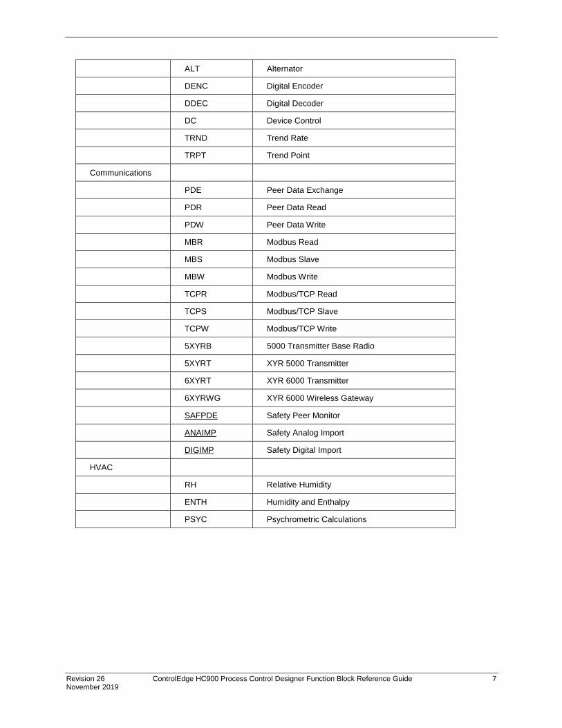
Revision 26 ControlEdge HC900 Process Control Designer Function Block Reference Guide 7 November 2019
ALT Alternator
DENC Digital Encoder
DDEC Digital Decoder
DC Device Control
TRND Trend Rate
TRPT Trend Point
Communications
PDE Peer Data Exchange
PDR Peer Data Read
PDW Peer Data Write
MBR Modbus Read
MBS Modbus Slave
MBW Modbus Write
TCPR Modbus/TCP Read
TCPS Modbus/TCP Slave
TCPW Modbus/TCP Write
5XYRB 5000 Transmitter Base Radio
5XYRT XYR 5000 Transmitter
6XYRT XYR 6000 Transmitter
6XYRWG XYR 6000 Wireless Gateway
SAFPDE Safety Peer Monitor
ANAIMP Safety Analog Import
DIGIMP Safety Digital Import
HVAC
RH Relative Humidity
ENTH Humidity and Enthalpy
PSYC Psychrometric Calculations
8 ControlEdge HC900 Process Control Designer Function Block Reference Guide Revision 26 November 2019
Table 2 Function blocks alphabetically
FUNCTION BLOCK IDENTIFICATION LABEL
BLOCK DESCRIPTION
ABS Absolute Value Function Block
ADD Addition 2 Input
4ADD Addition 4 Input
AGA8DL Gas Compressibility Detail Calc
AGA8GS Gas Compressibility Gross Method Calc
AGA3O Orifice Meter Calc
AGA7TM Turbine Meter Calc
AGA9UM Ultrasonic Meter Calc
AI Analog Input
AI-V Analog Input Voting
ALM Analog Alarm
ALMGR Alarm Group
4ALM 4 Alarm with Hysteresis
ALT Alternator
AMB Auto/Manual Bias Function Block
2AND AND – 2 Inputs
4AND AND – 4 Inputs
8AND AND – 8 Inputs
AO Analog Output
AO-V Analog Output Validated
ASYS Analog System Status
4MUL Multiplier (4 input)
4OR 4 - Input OR
4SUB 4 – Input Subtract
5XYRB 5000 Transmitter Base Radio
5XYRT XYR 5000 Transmitter
6XYRT XYR 6000 Transmitter
6XYRWG XYR 6000 Wireless Gateway
Revision 26 ControlEdge HC900 Process Control Designer Function Block Reference Guide 9 November 2019
8DI 8 Digital Inputs
8DO 8 Digital Outputs
8OR 8 – Input OR
AGA7TM Turbine Meter Calc
ANAIMP Safety Analog Import
BCD Binary Coded Decimal Translator
BOOL Boolean Logic
CALEVT Calendar Event
CARB Carbon Potential
CASTA Configuration Access Status
CAVG Continuous Average
CMPR Comparison Calculation
DC Device Control
DCMP Deviation Compare
DDEC Digital Decoder
DENC Digital Encoder
DEWP Dewpoint
DI Digital Inputs 2
DI-V Digital Input Voting
DIGIMP Safety Digital Import
DO-V Digital Output Validated
DLAY On Delay/Off Delay Timer
DO Digital Output
DSW Digital Switch
ENTH Humidity and Enthalpy
FGEN Function Generator
FI Frequency Input
FMON Fault Monitor
FRCP Force Present
FSS Four Selector Switch
FSYS Fast Logic System Monitor
HLLM High Low Limiter
HMON High Monitor
HOA Hand/Off/Auto Switch

10 ControlEdge HC900 Process Control Designer Function Block Reference Guide Revision 26 November 2019
HSEL High Selector
IMM IO Module Monitor
LDLG Lead/Lag
LMON Low Monitor
LPSW Loop Switch
LSEL Low Selector
LTCH Latch
MATH MATH
MALM Multiple Alarm with Hysteresis
MBR Modbus Read
MBS Modbus Slave
MBW Modbus Write
MDFL Mode Flag
MDSW Mode Switch
MMA Min/Max/Avg
MSF Mass Flow Calculation
MUL Multiplier
NEG Negate
NOT NOT
OFDT Off Delay Timer
ON ON/OFF
ONDT On Delay Timer
2OR 2 – Input OR
PB Pushbutton
PDE Peer Data Exchange
PDR Peer Data Read
PDW Peer Data Write
PI Pulse Input
PID PID
POUT Pulse Output
PSYC Psychrometric Calculations
PTMR Periodic Timer
QDT Quadrature
RACK I/O Rack Monitor
Revision 26 ControlEdge HC900 Process Control Designer Function Block Reference Guide 11 November 2019
RAMP RAMP
RCON Read Constant
RCP Recipe Selector
RH Relative Humidity
ROC Rate of Change
RSTAT Redundancy Status
RSW Rotary Switch
RTC Real Time Clock
RTMR Resettable Timer
SAFPDE Safety Peer Monitor
SCB Scale and Bias
SEQ Sequencer
SPEV Setpoint Programming Event Decoder
SPEV Setpoint Programming Event Decoder
SPS Setpoint Scheduler
SPSA Setpoint Scheduler Auxiliary Setpoint
SQRT Square Root
STFL Setpoint Scheduler Stage Flags
STG Stage
STK Stack Light
STRIG Selectable Trigger
STSW Setpoint Scheduler State Switch
SUB Subtraction
SW Analog Switch
SYNC Synchronize
TAHD Track and Hold
TCPR Modbus/TCP Read
TCPS Modbus/TCP Slave
TCPW Modbus/TCP Write
TGFF Toggle Flip Flop
TMDT Time and Date
TOT Totalizer
TPO Time Proportional Output
TPSC Three Position Step Control

12 ControlEdge HC900 Process Control Designer Function Block Reference Guide Revision 26 November 2019
TRIG Trigger
TRND Trend Rate
TRPT Trend Point
UPDN Up/Down
UIO-AI UIO Analog Input
UIO-AO UIO Analog Output
UIO-DI UIO Digital Input
UIO-DO UIO Digital Output
VLIM Velocity Limiter
WCON Write Constant
WTUN Write Tuning Constants
WVAR Write Variable
XFR Bumpless Analog Transfer Switch
XOR Exclusive OR

Revision 26 ControlEdge HC900 Process Control Designer Function Block Reference Guide 13 November 2019
ABS Absolute Value Function Block
Description The ABS label stands for Absolute Value.
This block is part of the Calculations category
Function Calculate the absolute value of a single analog variable input. Useful for ensuring a positive output value.
• OUT = [ X]
Input X = Analog value to be modified.
Output OUT = modified value.
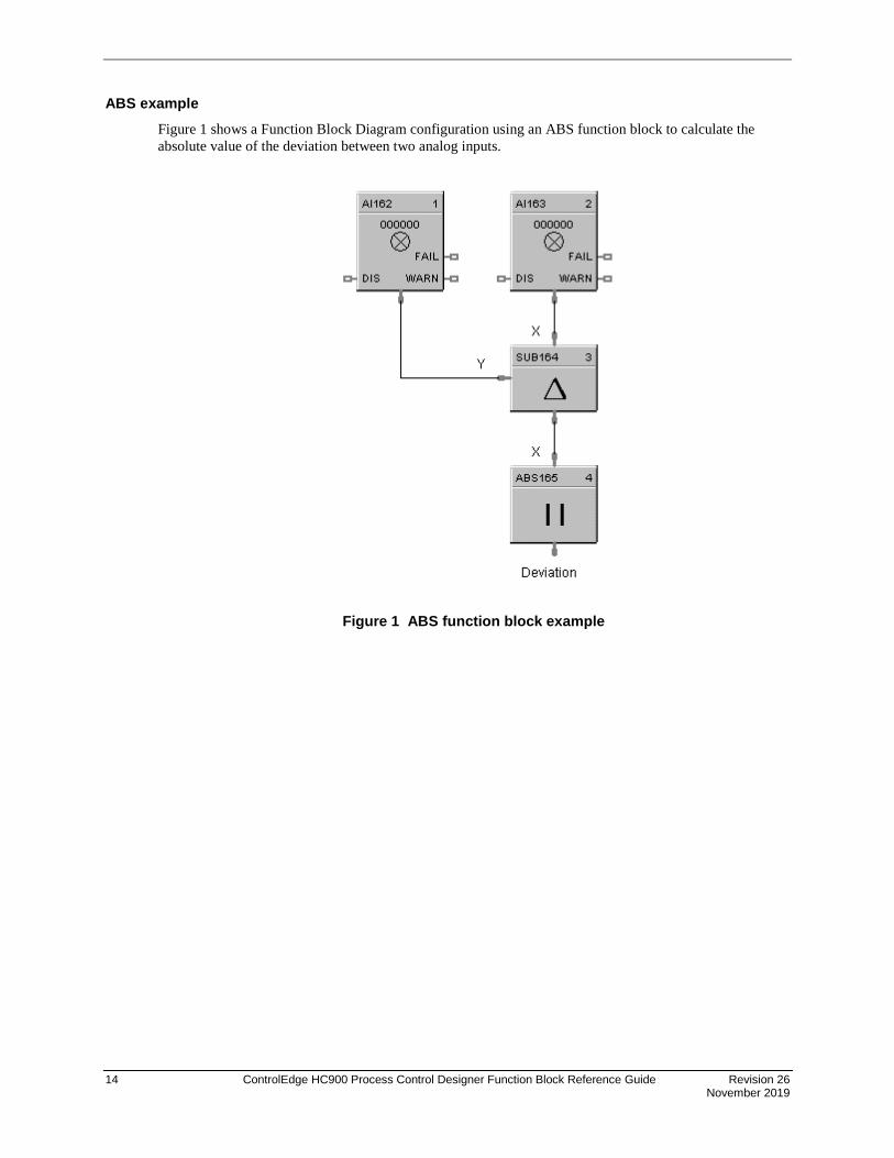
14 ControlEdge HC900 Process Control Designer Function Block Reference Guide Revision 26 November 2019
ABS example Figure 1 shows a Function Block Diagram configuration using an ABS function block to calculate the absolute value of the deviation between two analog inputs.
Figure 1 ABS function block example
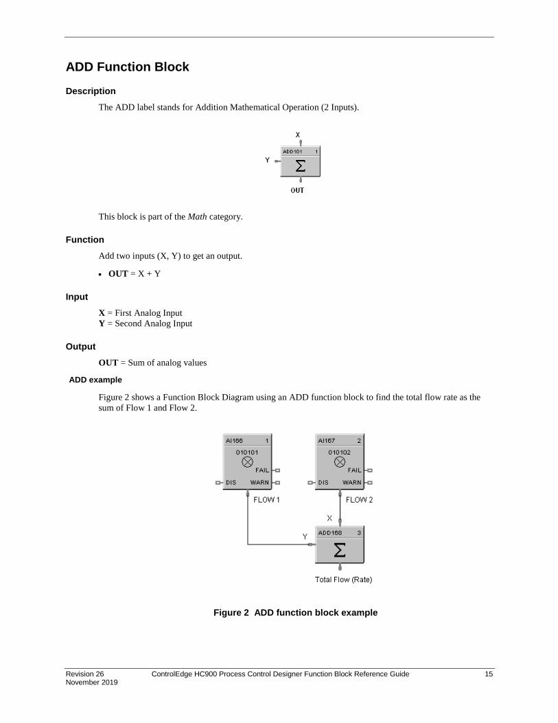
Revision 26 ControlEdge HC900 Process Control Designer Function Block Reference Guide 15 November 2019
ADD Function Block
Description The ADD label stands for Addition Mathematical Operation (2 Inputs).
This block is part of the Math category.
Function Add two inputs (X, Y) to get an output.
• OUT = X + Y
Input X = First Analog Input Y = Second Analog Input
Output OUT = Sum of analog values
ADD example
Figure 2 shows a Function Block Diagram using an ADD function block to find the total flow rate as the sum of Flow 1 and Flow 2.
Figure 2 ADD function block example

16 ControlEdge HC900 Process Control Designer Function Block Reference Guide Revision 26 November 2019
4ADD Function Block
Description The 4ADD label stands for Addition Mathematical Operation (4 Inputs).
This block is part of the Math category.
Function Add FOUR inputs (Y, X1, X2, and X3) to get an output.
• OUT = Y+ X1+ X2 + X3
Input Y =First Analog Input X1 = Second Analog Input X2 = Third Analog Input X3 = Fourth Analog Input
ATTENTION
All 4 inputs must be connected or unused inputs inverted. If only 3 inputs are used, the 4th value should be inverted or connected to a constant value of 1.0.
Output
OUT = Sum of the analog values
4ADD example Figure 3 shows a Function Block diagram using a 4ADD function block to find the total Flow rate as the sum of Flow 1, Flow 2, Flow 3, and Flow 4.
Figure 3 4ADD function block example

Revision 26 ControlEdge HC900 Process Control Designer Function Block Reference Guide 17 November 2019
AGA8DL Function Block Description
The AGA8DL label stands for Gas Compressibility Detail AGA8 Calculation.
METER BLOCK CONNECT
This block is part of the Calculations category.
Function The Detail method (AGA8DL) uses the gas analysis of up to 21 components. From the gas analysis, the super-compressibility factor, gas density at flowing and standard conditions, and gas relative density at standard conditions are calculated for input into the AGA calculation for the meter type chosen.
Used when accurate gas analysis is available either via an on-line gas analyzer or from laboratory measurements. The Detail method can handle up to 21 gas components typically found in natural gas. If this information is available, the Detail method is preferable, as accurate results are obtainable over a wider range of conditions than the Gross method.

18 ControlEdge HC900 Process Control Designer Function Block Reference Guide Revision 26 November 2019
Inputs TF = Temperature at flow in units selected by the UNITS configuration parameter. PF = Pressure at flow in units selected by the UNITS configuration parameter. HW = Differential pressure in the units selected by the UNITS configuration parameter. (Only required if the meter block is AGA3.) METH = Methane Mole Fraction NITRO = Nitrogen Mole Fraction CO2 = Carbon Dioxide Mole Fraction ETH = Ethane Mole Fraction PROP = Propane Mole Fraction H2O = Water Mole Fraction H2S = Hydrogen Sulfide Mole Fraction HYDRO = Hydrogen Mole Fraction CO = Carbon Monoxide Mole Fraction OXYGEN = Oxygen Mole Fraction I-BUT = i-Butune Mole Fraction N-BUT = n-Butane Mole Fraction I-PENT = i-Pentane Mole Fraction N-PENT = n-Pentane Mole Fraction HEX = Hexane Mole Fraction HEPT = Heptane Mole Fraction OCT = Octane Mole Fraction NON = Nonane Mole Fraction DEC = Decane Mole Fraction HEL = Helium Mole Fraction ARG = Argon Mole Fraction
Outputs RHOTP = Density at flow temperature and pressure conditions in units selected by the UNITS configuration parameter. RHOB = Density at base conditions in units selected by the UNITS configuration parameter. RHOS = Density at standard conditions in units selected by the UNITS configuration parameter. FPVS = Super-compressibility factor GRS = Real Gas relative density at 60 deg F/14.73 PSI GRS = (Mgas*Zair)/(Mair*Zgas) where Zair = .9995844 and Mair = 28.96256 HV = Heating Value in units selected by the UNITS configuration parameter. ERR = Set when calculation status is indicating an error condition. WARN = Set when calculation status is indicating a warning condition - STATUS = a status number is placed on this pin which can be used to find the error in the error/warning lookup table (See Table 5 AGA Error Codes). This enables the user to connect the pin to comparator blocks to distinguish various error/warning conditions in the function block configuration. METER BLK CONNECT = Must be connected to the companion meter block. This output connection provides multiple data for input to its associated meter function block, (AGA 3, 7, or 9), reducing the need to make multiple connections to complete the configuration.
Execution Order of this block must be set to be less than meter block (AGA3, 7, or 9) Execution Order for correct calculation sequence.

Revision 26 ControlEdge HC900 Process Control Designer Function Block Reference Guide 19 November 2019
Configuration parameters The AGA8DL properties dialog box is divided into two tab cards
GENERAL AGA8 - Detail
Click on the tab to access the properties for that tab.
GENERAL tab
Table 3 AGA8DL General tab configuration parameters
Properties Group Parameter Index # Parameter Description Value or Selection
Block Block Order Execution Order for Block Execution Order of this block must be set to be less than meter block (AGA3, 7, or 9) Execution Order for correct calculation sequence.
Read Only. To change block order, right-click on a Function Block and select Execution Order.
Tag Name N/A 16-character tag name (ASCII characters only)
Descriptor N/A Block description

20 ControlEdge HC900 Process Control Designer Function Block Reference Guide Revision 26 November 2019
AGA8 - Detail tab
Table 4 AGA8DL Detail tab configuration parameters
Properties Group Parameter Index # Parameter Description Value or Selection
Contract Conditions
TB Defines the Base or Contract Temperature to calculate volume flow rate at contract conditions in the units selected by the UNITS configuration parameter.
ºF for U.S Units
ºC for Metric Units
PB Defines the Base or Contract Pressure to calculate volume flow rate at contract conditions in the units selected by the UNITS configuration parameter.
psia for U.S Units
bar for Metric Units
Units U.S
Metric Type of units for all block
inputs, outputs, and configuration parameters: This selection must agree with the UNITS selection in the meter block. If they don’t agree, no error will be indicated on the error/calc status pins. The Meter block will detect the error, and will alert the user.
Click Radio Button to select.
Ensure that units and gauge pressure settings are consistent with the meter block.

Revision 26 ControlEdge HC900 Process Control Designer Function Block Reference Guide 21 November 2019
Properties Group Parameter Index # Parameter Description Value or Selection
Flowing Pressure Measurement
Use Gauge Pressure
Sets whether pressure measurements are absolute or gauge pressure. If you are using gauge pressure, a value of atmospheric pressure is required in the pressure units chosen.
Click on Radio Button to select. Ensure that units and gauge pressure settings are consistent with the meter block.
Atmospheric Pressure
Enter an Atmospheric pressure value in units selected by the UNITS configuration parameter
Gas Analysis Override Expanded Range Error
Under certain situations, the gas component values may exceed the expanded range recommended by the AGA 8 Report. Setting this checkbox will override the expanded range error so that a flow rate will be calculated. It should be noted that calculated flow rates for conditions where the expanded range is exceeded are outside of the recommended uncertainty values for AGA 8 calculations.
Check this box to Override the expanded Range Error
Use Remote Gas Component Values
If using this setting, the gas component parameter pins X [1..21] are always visible whether or not this is selected. Unused pins can be left floating, since an unconnected pin is always read as 0. Note that the analyzer values must be normalized to ensure the gas component sum is equal to 1.0.
Check this box to use the block’s input pin values from an online analyzer.
Uncheck this box to use Local Gas Component Values.

22 ControlEdge HC900 Process Control Designer Function Block Reference Guide Revision 26 November 2019
Properties Group Parameter Index # Parameter Description Value or Selection
Local Gas Component Values
METH NITRO CO2 ETH PROP H2O H2S HYDRO CO OXYGEN I-BUT N-BUT I-PENT N-PENT HEX HEPT OCT NON DEC HEL ARG
Each of the 21 gas component fractions can be configured with either a constant fraction value derived from a lab report or from an on-line gas chromatograph.
< 1.0 and >= 0.0
The sum of the gas components should equal 1. HCDesigner will show the sum of the gas components to aid the user.
SUM Sum of the 21 gas entered (not active) values.
Read Only
Error Codes The AGA function blocks have a status pin that outputs a number that indicates the status of the block. This pin can be connected to comparator blocks to distinguish various error/warning conditions in the function block configuration.
Table 5 AGA Error Codes
Status number
Block type Severity Description
0 ALL Good OK – NO ERRORS OR WARNINGS ENCOUNTERED
1 AGA 8 - DETAIL Error PRESSURE HAS A NEGATIVE DERIVATIVE
2 AGA 8 - DETAIL Warning DENSITY IN BRAKET EXCEEDS MAXIMUM DEFAULT PROCEDURE USED
3 AGA 8 - DETAIL Error MAXIMUM ITERATIONS EXCEEDED IN BRAKET
4 AGA 8 - DETAIL Error MAXIMUM ITERATIONS IN DDETAIL EXCEEDED
5 AGA 8 - GROSS Error THE ROOT WAS NOT BOUNDED IN DGROSS
6 AGA 8 - GROSS Error NO CONVERGENCE IN DGROSS
7 AGA 8 - GROSS Error VIRGS SQUARE ROOT NEGATIVE
8 AGA 8 - GROSS Error COMBINED VALUES OF GRGR, X[2] AND HV NOT CONSISTENT
9 AGA 8 - GROSS Error INVALID TERM IN VIRGS
12 AGA 8 - GROSS Error FLOWING PRESSURE (PF) <= 0.0 PR > 1740.0 PSIA
13 AGA 8 - GROSS Error FLOWING TEMPERATURE (TF) < 14.0 OR > 149.0 DEG F
14 AGA 8 - GROSS Error HEATING VALUE (HV) < 477.0 OR > 1211.0 BTU/FT^3

Revision 26 ControlEdge HC900 Process Control Designer Function Block Reference Guide 23 November 2019
Status number
Block type Severity Description
15 AGA 8 - GROSS Error GAS RELATIVE DENSITY (GRGR) < 0.55 OR > 0.870
16 AGA 8 - GROSS Error MOLE FRACTION FOR N2 < 0.0 OR > 0.50
OR FOR CO2 < 0.0 OR > 0.30
OR FOR H2 < 0.0 OR > 0.10
OR FOR CO < 0.0 OR > 0.03
17 AGA 8 - GROSS Error REFERENCE TEMPERATURE < 32.0 OR > 77.O DEG F
18 AGA 8 - GROSS Error REFERENCE PRESSURE < 13.0 OR > 16.0 PSIA
22 AGA 8 - GROSS Warning FLOWING PRESSURE (PF) <=0.0 OR > 1200.0 PSIA
23 AGA 8 - GROSS Warning FLOWING TEMPERATURE (TF) < 32.0 OR > 130.0 DEG F
24 AGA 8 - GROSS Warning HEATING VALUE (HV) < 805.0 OR > 1208.0 BTU/FT^3
25 AGA 8 - GROSS Warning GAS RELATIVE DENSITY (GRGR) < 0.55 OR > 0.800
26 AGA 8 - GROSS Warning MOLE FRACTION FOR N2 < 0.0 OR > 0.20
OR FOR CO2 < 0.0 OR > 0.20
OR FOR H2 < 0.0 OR > 0.0
OR FOR CO < 0.0 OR > 0.0
32 AGA 8 - DETAIL Error FLOWING PRESSURE (PF) < 0.0 OR > 40,000. PSIA
33 AGA 8 - DETAIL Error FLOWING TEMPERATURE (TF) < -200 OR > 760 DEG F
36 AGA 8 - DETAIL Error MOLE FRACTION FOR METHANE < 0.0 OR > 1.0
FOR NITROGEN < 0.0 OR > 1.0
FOR CARBON DIOXIDE < 0.0 OR > 1.0
FOR ETHANE < 0.0 OR > 1.0
FOR PROPANE < 0.0 OR > 0.12
FOR WATER < 0.0 OR > 0.10
FOR H2S < 0.0 OR > 1.0
FOR HYDROGEN < 0.0 OR > 1.0
FOR CARBON MONOXIDE < 0.0 OR > 0.03
FOR OXYGEN < 0.0 OR > 0.21
FOR BUTANES < 0.0 OR > 0.06
FOR PENTANES < 0.0 OR > 0.04
FOR HEXANES + < 0.0 OR > 0.10
FOR HELIUM < 0.0 OR > 0.03
FOR ARGON < 0.0 OR > 1.0
37 AGA 8 - DETAIL Error REFERENCE TEMPERATURE < 32.0 OR > 77.0 DEG F
38 AGA 8 - DETAIL Error REFERENCE PRESSURE < 13.0 OR > 16.0 PSIA
39 AGA 8 - DETAIL Error SUM OF MOLE FRACTIONS < 0.98 OR > 1.020
42 AGA 8 - DETAIL Warning FLOWING PRESSURE (PF) < 0.0 OR > 1750. PSIA
43 AGA 8 - DETAIL Warning FLOWING TEMPERATURE (TF) < 17 OR > 143 DEG F
46 AGA 8 - DETAIL Warning MOLE FRACTION FOR METHANE < 0.45 OR > 1.0

24 ControlEdge HC900 Process Control Designer Function Block Reference Guide Revision 26 November 2019
Status number
Block type Severity Description
FOR NITROGEN < 0.0 OR > 0.5
FOR CARBON DIOXIDE < 0.0 OR > 0.3
FOR ETHANE < 0.0 OR > 0.1
FOR PROPANE < 0.0 OR > 0.04
FOR WATER < 0.0 OR > 0.0005
FOR H2S < 0.0 OR > 0.0002
FOR HYDROGEN < 0.0 OR > 0.1
FOR CARBON MONOXIDE < 0.0 OR > 0.03
FOR OXYGEN < 0.0 OR > 0.0
FOR BUTANES < 0.0 OR > 0.01
FOR PENTANES < 0.0 OR > 0.003
FOR HEXANES + < 0.0 OR > 0.002
FOR HELIUM < 0.0 OR > 0.002
FOR ARGON < 0.0 OR > 0.0
49 AGA 8 - DETAIL Warning SUM OF MOLE FRACTIONS < 0.9999 OR > 1.0001
52 AGA 3 - ORIFICE Error FLOWING PRESSURE WAS <= 0.0 OR > 40000. PSIA
53 AGA 3 - ORIFICE Error FLOWING TEMPERATURE < -200. OR > 760. DEG F
55 AGA 3 - ORIFICE Error ORIFICE DIAMETER WAS >= 100.0 INCHES
56 AGA 3 - ORIFICE Error PIPE DIAMETER WAS >= 100.0 INCHES
57 AGA 3 - ORIFICE Error FLOWING OR STANDARD DENSITY WAS <= 0.0 LBM/FT^3
58 AGA 3 - ORIFICE Error DIFFERENTIAL PRESSURE WAS <= 0.0 INCHES H2O
65 AGA 3 – ORIFICE Error SUPERCOMPRESSIBILITY FACTOR WAS <= 0.0
66 AGA 3 – ORIFICE Error RELATIVE DENSITY AT STANDARD CONDITIONS WAS < 0.07 OR > 1.52
68 AGA 3 – ORIFICE Error COMPRESSIBILITY FACTOR AT STANDARD CONDITIONS <= 0.0
69 AGA 3 – ORIFICE Error BETA RATIO (DO/DM) <= 0.0 OR => 1.0
75 AGA 3 – ORIFICE Warning ORIFICE DIAMETER WAS < = 0.45 INCHES
76 AGA 3 – ORIFICE Warning PIPE DIAMETER WAS <= 2.0 INCHES
77 GENERAL CONFIG
Error ERROR INVALID COMPANION BLOCK INTERCONNECTION
78 GENERAL CONFIG
Error METER/COMPRESSIBLITY BLOCK UNITS ARE INCONSISTENT
79 AGA 3 - ORIFICE Warning BETA RATIO (DO/DM) WAS < 0.1 OR > 0.75
99 GENERAL OPERATION
N/A Block is disabled – process value outputs are set to 0 and error/warning pins are turned off.

Revision 26 ControlEdge HC900 Process Control Designer Function Block Reference Guide 25 November 2019
Example
Figure 4 AGA8DL function block example

26 ControlEdge HC900 Process Control Designer Function Block Reference Guide Revision 26 November 2019
AGA8GS Function Block Description
The AGA8GS label stands for Gas Compressibility Gross Method AGA8 Calculation
METER BLK CONNECT
This block is part of the Calculations category.
Function The Gross method is used to approximate natural gas by treating it as a mixture of three components, equivalent hydrocarbon component, Nitrogen and Carbon Dioxide. It is typically used for dry, sweet (no H2S) natural gas. There are two methods used:
Gross Method 1 calculates the super-compressibility and gas density from knowledge of the relative density, heating value and carbon dioxide, hydrogen and carbon monoxide components.
Gross Method 2 calculates the super-compressibility and gas density from knowledge of the relative density, Nitrogen, carbon dioxide, hydrogen and carbon monoxide components.
The Gross Method only works over a limited range of conditions but requires less instrumentation to implement.
Inputs TF = Temperature at flow in units selected by the UNITS configuration parameter. PF = Pressure at flow in units selected by the UNITS configuration parameter. HW = Differential pressure in the units selected by the UNITS configuration parameter. (Only required if the meter block is AGA3.) CO2 = Carbon Dioxide Mole Fraction HYD = Hydrogen Mole Fraction CO = Carbon Monoxide Mole Fraction NITRGN = Nitrogen Mole Fraction (Method 2 only)
Outputs RHOTP = Density at flow temperature and pressure conditions in units selected by the UNITS configuration parameter. RHOB = Density at base conditions in units selected by the UNITS configuration parameter. RHOS = Density at standard conditions in units selected by the UNITS configuration parameter. FPVS = Super-compressibility factor GRS = Real Gas relative density at 60 deg F/14.73 PSI GRS = (Mgas*Zair)/(Mair*Zgas) where Zair = .9995844 and Mair = 28.96256
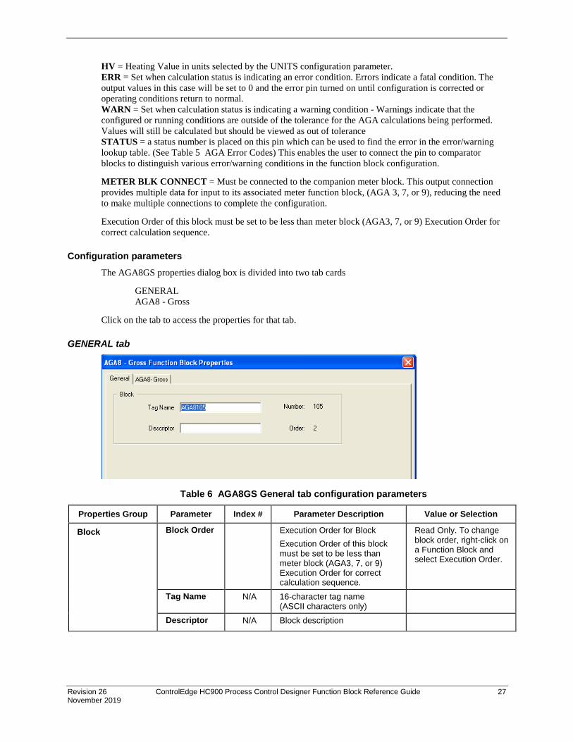
Revision 26 ControlEdge HC900 Process Control Designer Function Block Reference Guide 27 November 2019
HV = Heating Value in units selected by the UNITS configuration parameter. ERR = Set when calculation status is indicating an error condition. Errors indicate a fatal condition. The output values in this case will be set to 0 and the error pin turned on until configuration is corrected or operating conditions return to normal. WARN = Set when calculation status is indicating a warning condition - Warnings indicate that the configured or running conditions are outside of the tolerance for the AGA calculations being performed. Values will still be calculated but should be viewed as out of tolerance STATUS = a status number is placed on this pin which can be used to find the error in the error/warning lookup table. (See Table 5 AGA Error Codes) This enables the user to connect the pin to comparator blocks to distinguish various error/warning conditions in the function block configuration.
METER BLK CONNECT = Must be connected to the companion meter block. This output connection provides multiple data for input to its associated meter function block, (AGA 3, 7, or 9), reducing the need to make multiple connections to complete the configuration.
Execution Order of this block must be set to be less than meter block (AGA3, 7, or 9) Execution Order for correct calculation sequence.
Configuration parameters The AGA8GS properties dialog box is divided into two tab cards
GENERAL AGA8 - Gross
Click on the tab to access the properties for that tab.
GENERAL tab
Table 6 AGA8GS General tab configuration parameters
Properties Group Parameter Index # Parameter Description Value or Selection
Block Block Order Execution Order for Block Execution Order of this block must be set to be less than meter block (AGA3, 7, or 9) Execution Order for correct calculation sequence.
Read Only. To change block order, right-click on a Function Block and select Execution Order.
Tag Name N/A 16-character tag name (ASCII characters only)
Descriptor N/A Block description

28 ControlEdge HC900 Process Control Designer Function Block Reference Guide Revision 26 November 2019
AGA8 – Gross tab
Table 7 AGA8GS Detail tab configuration parameters
Properties Group
Parameter Index # Parameter Description Value or Selection
Gross Method Used
Method 1 Gross Method 1 calculates the super-compressibility and gas density from knowledge of the relative density, heating value and carbon dioxide, hydrogen and carbon monoxide components.
Click on Radio Button to select
Method 2 Gross Method 2 calculates the super-compressibility and gas density from knowledge of the relative density, Nitrogen, carbon dioxide, hydrogen and carbon monoxide components.
Click on Radio Button to select
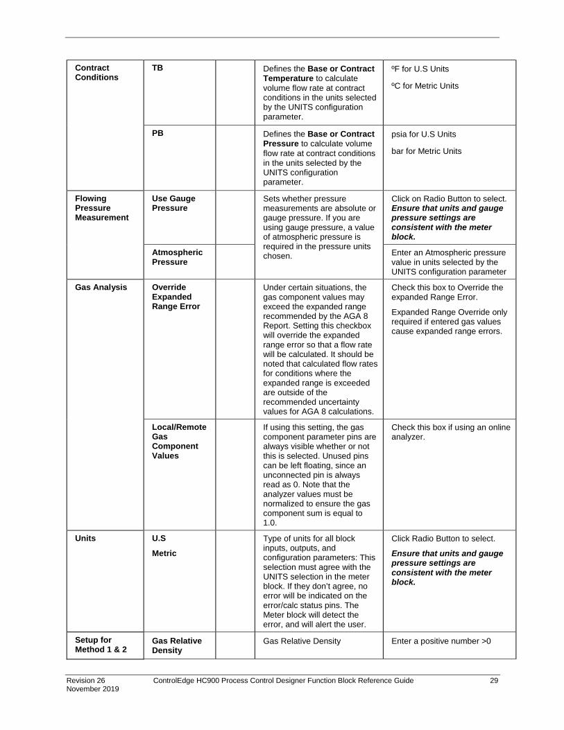
Revision 26 ControlEdge HC900 Process Control Designer Function Block Reference Guide 29 November 2019
Contract Conditions
TB Defines the Base or Contract Temperature to calculate volume flow rate at contract conditions in the units selected by the UNITS configuration parameter.
ºF for U.S Units
ºC for Metric Units
PB Defines the Base or Contract Pressure to calculate volume flow rate at contract conditions in the units selected by the UNITS configuration parameter.
psia for U.S Units
bar for Metric Units
Flowing Pressure Measurement
Use Gauge Pressure
Sets whether pressure measurements are absolute or gauge pressure. If you are using gauge pressure, a value of atmospheric pressure is required in the pressure units chosen.
Click on Radio Button to select. Ensure that units and gauge pressure settings are consistent with the meter block.
Atmospheric Pressure
Enter an Atmospheric pressure value in units selected by the UNITS configuration parameter
Gas Analysis Override Expanded Range Error
Under certain situations, the gas component values may exceed the expanded range recommended by the AGA 8 Report. Setting this checkbox will override the expanded range error so that a flow rate will be calculated. It should be noted that calculated flow rates for conditions where the expanded range is exceeded are outside of the recommended uncertainty values for AGA 8 calculations.
Check this box to Override the expanded Range Error.
Expanded Range Override only required if entered gas values cause expanded range errors.
Local/Remote Gas Component Values
If using this setting, the gas component parameter pins are always visible whether or not this is selected. Unused pins can be left floating, since an unconnected pin is always read as 0. Note that the analyzer values must be normalized to ensure the gas component sum is equal to 1.0.
Check this box if using an online analyzer.
Units
U.S
Metric Type of units for all block
inputs, outputs, and configuration parameters: This selection must agree with the UNITS selection in the meter block. If they don’t agree, no error will be indicated on the error/calc status pins. The Meter block will detect the error, and will alert the user.
Click Radio Button to select.
Ensure that units and gauge pressure settings are consistent with the meter block.
Setup for Method 1 & 2
Gas Relative Density
Gas Relative Density Enter a positive number >0

30 ControlEdge HC900 Process Control Designer Function Block Reference Guide Revision 26 November 2019
Rel Density Ref Temp
Relative density reference temperature in units selected by the UNITS configuration parameter.
Enter a positive number >0
Rel Density Ref Pres
Relative density reference pressure in units selected by the UNITS configuration parameter.
Enter a positive number >0
Setup for Method 1 only
Heating Value Heating value in units selected by the UNITS configuration parameter.
Enter a value from -99999 to 99999
Calorimeter Ref Temp
Calorimeter reference temperature in units selected by the UNITS configuration parameter.
Enter a value from -99999 to 99999
Calorimeter Ref Pres
Calorimeter reference pressure in units selected by the UNITS configuration parameter.
Enter a value from -99999 to 99999
Combustion Ref Temp
Combustion reference temperature in units selected by the UNITS configuration parameter.
Enter a value from -99999 to 99999
Gas Components
CO2 HYDROGEN CO NITROGEN
Each of the 4 gas component fractions can be configured with either a constant fraction value derived from a lab report or from an on-line gas chromatograph.
< 1.0 and >= 0.0
The sum of the gas components should equal 1.

Revision 26 ControlEdge HC900 Process Control Designer Function Block Reference Guide 31 November 2019
Example
Figure 5 AGA8GS function block example
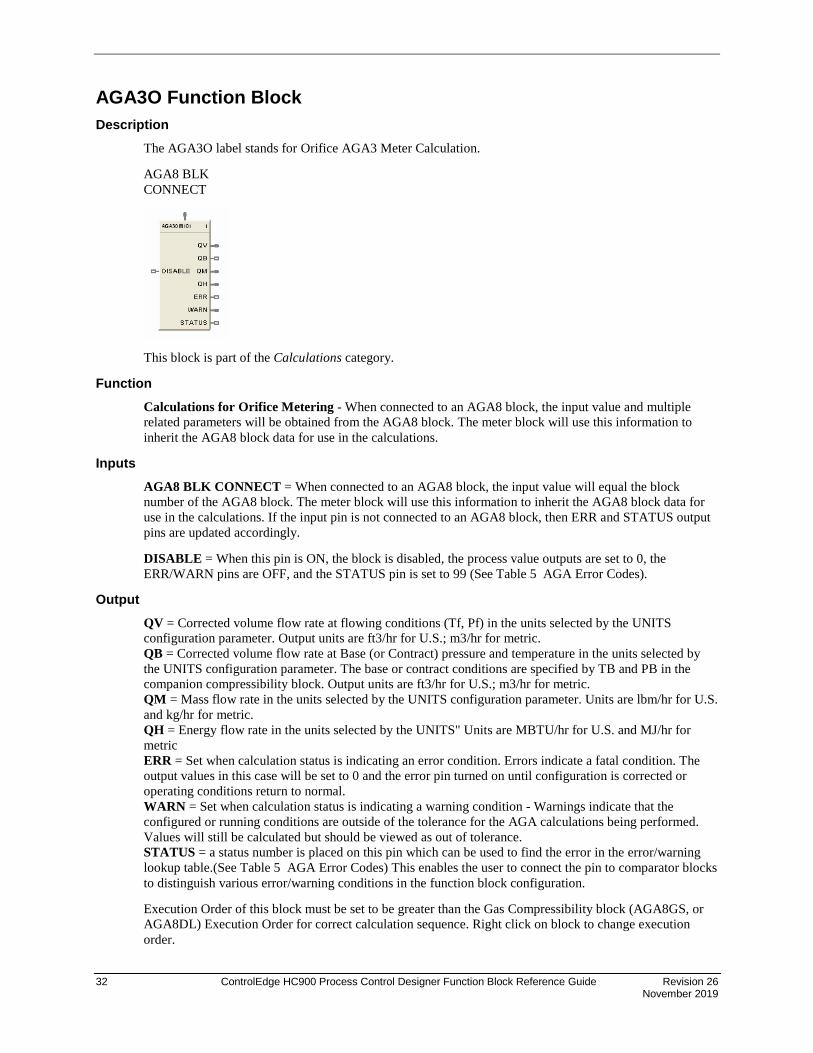
32 ControlEdge HC900 Process Control Designer Function Block Reference Guide Revision 26 November 2019
AGA3O Function Block Description
The AGA3O label stands for Orifice AGA3 Meter Calculation.
AGA8 BLK CONNECT
This block is part of the Calculations category.
Function Calculations for Orifice Metering - When connected to an AGA8 block, the input value and multiple related parameters will be obtained from the AGA8 block. The meter block will use this information to inherit the AGA8 block data for use in the calculations.
Inputs AGA8 BLK CONNECT = When connected to an AGA8 block, the input value will equal the block number of the AGA8 block. The meter block will use this information to inherit the AGA8 block data for use in the calculations. If the input pin is not connected to an AGA8 block, then ERR and STATUS output pins are updated accordingly.
DISABLE = When this pin is ON, the block is disabled, the process value outputs are set to 0, the ERR/WARN pins are OFF, and the STATUS pin is set to 99 (See Table 5 AGA Error Codes).
Output QV = Corrected volume flow rate at flowing conditions (Tf, Pf) in the units selected by the UNITS configuration parameter. Output units are ft3/hr for U.S.; m3/hr for metric. QB = Corrected volume flow rate at Base (or Contract) pressure and temperature in the units selected by the UNITS configuration parameter. The base or contract conditions are specified by TB and PB in the companion compressibility block. Output units are ft3/hr for U.S.; m3/hr for metric. QM = Mass flow rate in the units selected by the UNITS configuration parameter. Units are lbm/hr for U.S. and kg/hr for metric. QH = Energy flow rate in the units selected by the UNITS" Units are MBTU/hr for U.S. and MJ/hr for metric ERR = Set when calculation status is indicating an error condition. Errors indicate a fatal condition. The output values in this case will be set to 0 and the error pin turned on until configuration is corrected or operating conditions return to normal. WARN = Set when calculation status is indicating a warning condition - Warnings indicate that the configured or running conditions are outside of the tolerance for the AGA calculations being performed. Values will still be calculated but should be viewed as out of tolerance. STATUS = a status number is placed on this pin which can be used to find the error in the error/warning lookup table.(See Table 5 AGA Error Codes) This enables the user to connect the pin to comparator blocks to distinguish various error/warning conditions in the function block configuration.
Execution Order of this block must be set to be greater than the Gas Compressibility block (AGA8GS, or AGA8DL) Execution Order for correct calculation sequence. Right click on block to change execution order.

Revision 26 ControlEdge HC900 Process Control Designer Function Block Reference Guide 33 November 2019
Configuration parameters The AGA3O properties dialog box is divided into two tab cards
AGA3-Orifice Flow Rates
Click on the tab to access the properties for that tab.
AGA3-Orifice tab
Table 8 AGA3O Orifice tab configuration parameters
Properties Group Parameter Index # Parameter Description Value or Selection
Plate and Pipe Parameters
Orifice Diameter
Orifice diameter in the units selected by the UNITS configuration parameter.
Enter a value >0 Default = 1.0. U.S = in Metric = mm
Pipe Diameter Pipe diameter in the units selected by the UNITS configuration parameter.
Enter a value >0 Default = 1.0. U.S = in Metric = mm
Calibration Factor
Combined calibration factor of Orifice meter. If not specified use a value of 1.0. > 0.0
Enter a value Default = 1.0
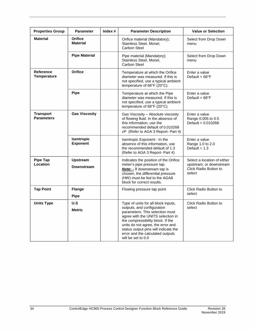
34 ControlEdge HC900 Process Control Designer Function Block Reference Guide Revision 26 November 2019
Properties Group Parameter Index # Parameter Description Value or Selection
Material Orifice Material
Orifice material (Mandatory); Stainless Steel, Monel, Carbon Steel
Select from Drop Down menu
Pipe Material Pipe material (Mandatory); Stainless Steel, Monel, Carbon Steel
Select from Drop Down menu
Reference Temperature
Orifice Temperature at which the Orifice diameter was measured. If this is not specified, use a typical ambient temperature of 68°F (20°C).
Enter a value Default = 68°F
Pipe Temperature at which the Pipe diameter was measured. If this is not specified, use a typical ambient temperature of 68°F (20°C).
Enter a value Default = 68°F
Transport Parameters
Gas Viscosity Gas Viscosity – Absolute viscosity of flowing fluid. In the absence of this information, use the recommended default of 0.010268 cP (Refer to AGA 3 Report- Part 4)
Enter a value Range 0.005 to 0.5 Default = 0.010268
Isentropic Exponent
Isentropic Exponent - In the absence of this information, use the recommended default of 1.3 (Refer to AGA 3 Report- Part 4)
Enter a value Range 1.0 to 2.0 Default = 1.3
Pipe Tap Location
Upstream
Downstream Indicates the position of the Orifice
meter’s pipe pressure tap. Note: - If downstream tap is chosen, the differential pressure (HW) must be fed to the AGA8 block for correct results.
Select a location of either upstream, or downstream Click Radio Button to select
Tap Point Flange
Pipe
Flowing pressure tap point Click Radio Button to select
Units Type U.S
Metric Type of units for all block inputs,
outputs, and configuration parameters: This selection must agree with the UNITS selection in the compressibility block. If the units do not agree, the error and status output pins will indicate the error and the calculated outputs will be set to 0.0
Click Radio Button to select
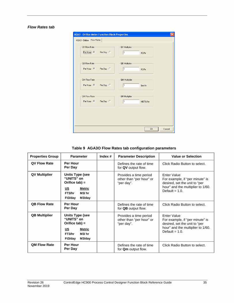
Revision 26 ControlEdge HC900 Process Control Designer Function Block Reference Guide 35 November 2019
Flow Rates tab
Table 9 AGA3O Flow Rates tab configuration parameters
Properties Group Parameter Index # Parameter Description Value or Selection
QV Flow Rate Per Hour Per Day
Defines the rate of time for QV output flow.
Click Radio Button to select.
QV Multiplier Units Type (see “UNITS” on Orifice tab) = US Metric FT3/hr M3/ hr Ft3/day M3/day
Provides a time period other than “per hour” or “per day”.
Enter Value For example, if “per minute” is desired, set the unit to “per hour” and the multiplier to 1/60. Default = 1.0.
QB Flow Rate Per Hour Per Day
Defines the rate of time for QB output flow.
Click Radio Button to select.
QB Multiplier Units Type (see “UNITS” on Orifice tab) = US Metric FT3/hr M3/ hr Ft3/day M3/day
Provides a time period other than “per hour” or “per day”.
Enter Value For example, if “per minute” is desired, set the unit to “per hour” and the multiplier to 1/60. Default = 1.0.
QM Flow Rate Per Hour Per Day
Defines the rate of time for Qm output flow.
Click Radio Button to select.

36 ControlEdge HC900 Process Control Designer Function Block Reference Guide Revision 26 November 2019
Properties Group Parameter Index # Parameter Description Value or Selection
QM Multiplier Units Type (see “UNITS” on Orifice tab) = US Metric lbm/hr Kg/hr lbm/day Kg/day
Provides a time period other than “per hour” or “per day”.
Enter Value For example, if “per minute” is desired, set the unit to “per hour” and the multiplier to 1/60. Default = 1.0.
QH Flow Rate Per Hour Per Day
Defines the rate of time for QH output flow.
Click Radio Button to select.
QH Multiplier Units Type (see “UNITS” on Orifice tab) = US Metric MBTU/hr MJ/ hr MBTU/day MJ/ day
Provides a time period other than “per hour” or “per day”.
Enter Value For example, if “per minute” is desired, set the unit to “per hour” and the multiplier to 1/60. Default = 1.0.
Example
Figure 6 AGA3O function block example

Revision 26 ControlEdge HC900 Process Control Designer Function Block Reference Guide 37 November 2019
AGA7TM Function Block Description
The AGA7TM label stands for Turbine AGA7 Meter Calculation and also applies to Rotary, Diaphragm, UltraSonic and Fluidic Oscillation Gas Meters.
AGA8 BLK CONNECT
This block is part of the Calculations category.
Function Calculations for gas measurement by Turbine Meters - When connected to an AGA8 block, the input value and multiple related parameters will be obtained from the AGA8 block. The meter block will use this information to inherit the AGA8 block data for use in the calculations.
Inputs QR = Raw Flow Rate in the units selected by the UNITS configuration parameter. U.S. is ft3/hr and Metric is m3/hr.
AGA8 BLK CONNECT = When connected to an AGA8 block, the input value will equal the block number of the AGA8 block. The meter block will use this information to inherit the AGA8 block data for use in the calculations. If the input pin is not connected to an AGA8 block, then ERR and STATUS output pins are updated accordingly.
DISABLE = When this pin is ON, the block is disabled, the process value outputs are set to 0, the ERR pin is OFF, and the STATUS pin is set to 99 (See Table 5 AGA Error Codes).
Outputs QV = Corrected volume flow rate at flowing conditions (Tf,Pf) in the units selected by the UNITS configuration parameter. Output units are "ft3/hr" U.S. and “m3/hr” for metric. QB = Corrected volume flow rate at Base (or Contract) pressure and temperature in the units selected by the UNITS configuration parameter. Base or Contract conditions are specified by TB and PB in the companion compressibility block. Output units are "ft3/hr" U.S. and “m3/hr” for metric. QM = Mass flow rate in the units selected by the UNITS configuration parameter." Units are lbm/hr for U.S. and kg/hr for metric. QH = Energy flow rate in the units selected by the UNITS. Units are MBTU/hr for U.S. and MJ/hr for metric. ERR = Set when calculation status is indicating an error condition. Errors indicate a fatal condition. The output values in this case will be set to 0 and the error pin turned on until configuration is corrected or operating conditions return to normal. STATUS = a status number is placed on this pin which can be used to find the error in the error/warning lookup table (See Table 5 AGA Error Codes). This enables the user to connect the pin to comparator blocks to distinguish various error/warning conditions in the function block configuration.
Execution Order of this block must be set to be greater than the Gas Compressibility block (AGA8GS, or AGA8DL) Execution Order for correct calculation sequence. Right click on block to change execution order.

38 ControlEdge HC900 Process Control Designer Function Block Reference Guide Revision 26 November 2019
Configuration parameters The AGA7TM properties dialog box is divided into two tab cards
AGA7-Turbine Flow Rates
Click on the tab to access the properties for that tab.
AGA7-Turbine tab
Table 10 AGA7TM Turbine tab configuration parameters
Properties Group Parameter Index # Parameter Description Value or Selection
Turbine Meter Setup
Meter Factor A meter factor is a dimensionless term obtained by dividing the actual volume of gas passed through the meter by the corresponding meter indicated volume.
Value should default to 1 and be limited to >0.
Units U.S.
Metric Type of units for all block
inputs, outputs, and configuration parameters: This selection must agree with the UNITS selection in the meter block. If they don’t agree, no error will be indicated on the error/calc status pins. The Meter block will detect the error, and will alert the user.
Click Radio Button to select

Revision 26 ControlEdge HC900 Process Control Designer Function Block Reference Guide 39 November 2019
Flow Rates tab
Table 11 AGA7TM Flow Rates tab configuration parameters
Properties Group Parameter Index # Parameter Description Value or Selection
QV Flow Rate Per Hour Per Day
Defines the rate of time for QV output flow.
Click Radio Button to select.
QV Multiplier Units Type (see “UNITS” on Turbine tab) = US Metric FT3/hr M3/ hr Ft3/day M3/day
Provides a time period other than “per hour” or “per day”.
Enter Value For example, if “per minute” is desired, set the unit to “per hour” and the multiplier to 1/60. Default = 1.0.
QB Flow Rate Per Hour Per Day
Defines the rate of time for QB output flow.
Click Radio Button to select.
QB Multiplier Units Type (see “UNITS” on Turbine tab) = US Metric FT3/hr M3/ hr Ft3/day M3/day
Provides a time period other than “per hour” or “per day”.
Enter Value For example, if “per minute” is desired, set the unit to “per hour” and the multiplier to 1/60. Default = 1.0.
QM Flow Rate Per Hour Per Day
Defines the rate of time for Qm output flow.
Click Radio Button to select.
QM Multiplier Units Type (see “UNITS” on Turbine tab) = US Metric lbm/hr Kg/hr lbm/day Kg/day
Provides a time period other than “per hour” or “per day”.
Enter Value For example, if “per minute” is desired, set the unit to “per hour” and the multiplier to 1/60. Default = 1.0.
QH Flow Rate Per Hour Per Day
Defines the rate of time for QH output flow.
Click Radio Button to select.

40 ControlEdge HC900 Process Control Designer Function Block Reference Guide Revision 26 November 2019
Properties Group Parameter Index # Parameter Description Value or Selection
QH Multiplier Units Type (see “UNITS” on Turbine tab) = US Metric MBTU/hr MJ/ hr MBTU/day MJ/ day
Provides a time period other than “per hour” or “per day”.
Enter Value For example, if “per minute” is desired, set the unit to “per hour” and the multiplier to 1/60. Default = 1.0.
Example
Figure 7 AGA7TM function block example

Revision 26 ControlEdge HC900 Process Control Designer Function Block Reference Guide 41 November 2019
AGA9UM Function Block Description
The AGA9UM label stands for Ultrasonic AGA9 Meter Calculation.
AGA8 BLK CONNECT
This block is part of the Calculations category.
Function Calculations for gas flow measurements from multi-path Ultrasonic Meters - When connected to an AGA8 block, the input value and multiple related parameters will be obtained from the AGA8 block. The meter block will use this information to inherit the AGA8 block data for use in the calculations.
Inputs QR = Raw Flow Rate in the units selected by the UNITS configuration parameter. U.S. is ft3/hr and Metric is m3/hr.
AGA8 BLK CONNECT = When connected to an AGA8 block, the input value will equal the block number of the AGA8 block. The meter block will use this information to inherit the AGA8 block data for use in the calculations. If the input pin is not connected to an AGA8 block, then ERR and STATUS output pins are updated accordingly.
DISABLE = When this pin is ON, the block is disabled, the process value outputs are set to 0, the ERR pin is OFF, and the STATUS pin is set to 99 (See Table 5 AGA Error Codes).
Outputs QV = Corrected volume flow rate at flowing conditions (Tf,Pf) in the units selected by the UNITS configuration parameter. Output units are "ft3/hr" U.S. and “m3/hr” for metric. QB = Corrected volume flow rate at Base (or Contract) pressure and temperature in the units selected by the UNITS configuration parameter. Base or Contract conditions are specified by TB and PB in the companion compressibility block. Output units are "ft3/hr" U.S. and “m3/hr” for metric. QM = Mass flow rate in the units selected by the UNITS configuration parameter." Units are lbm/hr for U.S. and kg/hr for metric. QH = Energy flow rate in the units selected by the UNITS. Units are MBTU/hr for U.S. and MJ/hr for metric. ERR = Set when calculation status is indicating an error condition. Errors indicate a fatal condition. The output values in this case will be set to 0 and the error pin turned on until configuration is corrected or operating conditions return to normal. STATUS = a status number is placed on this pin which can be used to find the error in the error/warning lookup table (See Table 5 AGA Error Codes). This enables the user to connect the pin to comparator blocks to distinguish various error/warning conditions in the function block configuration.
Execution Order of this block must be set to be greater than the Gas Compressibility block (AGA8GS, or AGA8DL) Execution Order for correct calculation sequence. Right click on block to change execution order.
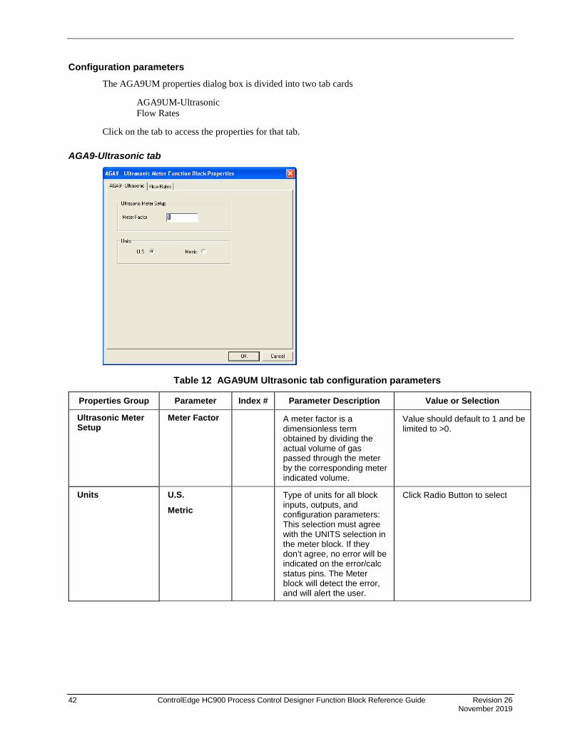
42 ControlEdge HC900 Process Control Designer Function Block Reference Guide Revision 26 November 2019
Configuration parameters The AGA9UM properties dialog box is divided into two tab cards
AGA9UM-Ultrasonic Flow Rates
Click on the tab to access the properties for that tab.
AGA9-Ultrasonic tab
Table 12 AGA9UM Ultrasonic tab configuration parameters
Properties Group Parameter Index # Parameter Description Value or Selection
Ultrasonic Meter Setup
Meter Factor A meter factor is a dimensionless term obtained by dividing the actual volume of gas passed through the meter by the corresponding meter indicated volume.
Value should default to 1 and be limited to >0.
Units U.S.
Metric Type of units for all block
inputs, outputs, and configuration parameters: This selection must agree with the UNITS selection in the meter block. If they don’t agree, no error will be indicated on the error/calc status pins. The Meter block will detect the error, and will alert the user.
Click Radio Button to select

Revision 26 ControlEdge HC900 Process Control Designer Function Block Reference Guide 43 November 2019
Flow Rates tab
Table 13 AGA9UM Flow Rates tab configuration parameters
Properties Group Parameter Index # Parameter Description Value or Selection
QV Flow Rate Per Hour Per Day
Defines the rate of time for QV output flow.
Click Radio Button to select.
QV Multiplier Units Type (see “UNITS” on Ultrasonic tab) =
US Metric FT3/hr M3/ hr Ft3/day M3/day
Provides a time period other than “per hour” or “per day”.
Enter Value For example, if “per minute” is desired, set the unit to “per hour” and the multiplier to 1/60. Default = 1.0.
QB Flow Rate Per Hour Per Day
Defines the rate of time for QB output flow.
Click Radio Button to select.
QB Multiplier Units Type (see “UNITS” on Ultrasonic tab) =
US Metric FT3/hr M3/ hr Ft3/day M3/day
Provides a time period other than “per hour” or “per day”.
Enter Value For example, if “per minute” is desired, set the unit to “per hour” and the multiplier to 1/60. Default = 1.0.
QM Flow Rate Per Hour Per Day
Defines the rate of time for Qm output flow.
Click Radio Button to select.
QM Multiplier Units Type (see “UNITS” on Ultrasonic tab) = US Metric lbm/hr Kg/hr lbm/day Kg/day
Provides a time period other than “per hour” or “per day”
Enter Value For example, if “per minute” is desired, set the unit to “per hour” and the multiplier to 1/60. Default = 1.0.
QH Flow Rate Per Hour Per Day
Defines the rate of time for QH output flow.
Click Radio Button to select.

44 ControlEdge HC900 Process Control Designer Function Block Reference Guide Revision 26 November 2019
Properties Group Parameter Index # Parameter Description Value or Selection
QH Multiplier Units Type (see “UNITS” on Ultrasonic tab) =
US Metric MBTU/hr MJ/ hr MBTU/ day
MJ/ day
Provides a time period other than “per hour” or “per day”
Enter Value. For example, if “per minute” is desired, set the unit to “per hour” and the multiplier to 1/60. Default = 1.0.
Example
Figure 8 AGA9UM function block example
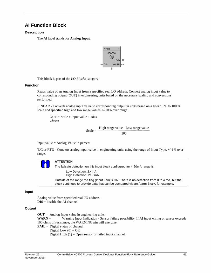
Revision 26 ControlEdge HC900 Process Control Designer Function Block Reference Guide 45 November 2019
AI Function Block Description
The AI label stands for Analog Input.
This block is part of the I/O Blocks category.
Function Reads value of an Analog Input from a specified real I/O address. Convert analog input value to corresponding output (OUT) in engineering units based on the necessary scaling and conversions performed.
LINEAR - Converts analog input value to corresponding output in units based on a linear 0 % to 100 % scale and specified high and low range values +/-10% over range.
OUT = Scale x Input value + Bias where:
Input value = Analog Value in percent
T/C or RTD - Converts analog input value in engineering units using the range of Input Type. +/-1% over range.
ATTENTION The failsafe detection on this input block configured for 4-20mA range is: Low Detection: 2.4mA High Detection: 21.6mA Outside of the range the flag (Input Fail) is ON. There is no detection from 0 to 4 mA, but the block continues to provide data that can be compared via an Alarm Block, for example.
Input
Analog value from specified real I/O address. DIS = disable the AI channel
Output OUT = Analog Input value in engineering units. WARN = Warning Input Indication - Sensor failure possibility. If AI input wiring or sensor exceeds 100 ohms of resistance, the WARNING pin will energize. FAIL = Digital status of channel Digital Low (0) = OK Digital High (1) = Open sensor or failed input channel.
High range value - Low range value100
Scale =

46 ControlEdge HC900 Process Control Designer Function Block Reference Guide Revision 26 November 2019
Configuration parameters
Table 14 Analog Input configuration parameters
Parameter Index # Parameter Description Value or Selection Block Order N/A Execution Order for Block Read Only. To
change block order, right-click on a Function Block and select Execution Order.
Rack Address
This is the address of the selected Rack.
Enter a value from 1 to 12.
I/O Module Address
Address of selected I/O module Enter a value: from 1 to 12
Channel Address
Channel on selected I/O Module Enter a value: from 1 to 8 or 16.
Input Type and Range
N/A Thermocouple Input types RTD Input types Linear Input types Special Input Types - Carbon or Oxygen
Click on the "Input Type and Range" group button and select an input from list box.
See
Table 15 for Input Type and Range

Revision 26 ControlEdge HC900 Process Control Designer Function Block Reference Guide 47 November 2019
Parameter Index # Parameter Description Value or Selection High Range Value
6 For Linear Inputs Only - output value that corresponds to 100% input value. For example: Actuation Input = 4-20mA Process variable = Flow Range of Flow = 0 to 250 gal/min High Range Display Value = 250 Low range Display Value = 0 Then 20mA = 250, 4mA = 0
Enter a value: - 99999 to 99999
Low Range Value
7 For Linear Inputs Only - output value that corresponds to 0 % input value For example: See “High Range Value”.
Enter a value: - 99999 to 99999
Disable Channel Output Value
8 The output value when the AI channel is disabled. Disable = ON
Enter a value Default = 0
Filter Time (sec)
2 A software digital filter is provided for the input designated to smooth the input. You can configure the first order lag time constant from 1 to 120 seconds. 0=no filter
Enter a value: 0 to 120 seconds
Bias 3 Bias is used to compensate the input for drift of an input value due to deterioration of a sensor, or some other cause.
Enter a value: -9999 to 99999
Failsafe Use Value
N/A Use the User value entered in the appropriate field.
Click on Radio button to select
Failsafe Use Value field
4 The output value to which the output will go to protect against the effects of failure of the equipment, such as, fuel shut-off if there is loss of flame in a furnace, or a sensor break.
Enter a value in Engineering Units -9999 to 99999
Downscale N/A LINEAR OUT = Value set at “Low range value” field. T/C or RTD OUT = Value of Low range implied by input type.
Click on Radio button to select
Upscale LINEAR OUT = Value set at “High range value” field. T/C or RTD OUT = Value of High range implied by input type.
Click on Radio button to select
Burnout Check
N/A Burnout check enable (Thermocouples only)
Click on block to select or deselect
Bad Channel Detection
N/A Check this to generate a hardware failure diagnostic if a bad AI channel is detected. If unchecked, a diagnostic will not be generated, which may be desirable for inputs used for monitoring only.
Click on block to select or deselect

48 ControlEdge HC900 Process Control Designer Function Block Reference Guide Revision 26 November 2019
Failsafe rules If the controller is unable to access the physical channel or the sensor is faulty, and:
• If Failsafe is “Use Value” Then OUT = Configured Failsafe value • If Failsafe is enabled and downscale Then OUT = Range Lo (linear)
Low Range Value of input type (T/C and RTD) • If Failsafe is enabled and upscale Then OUT = Range Hi (linear)
High Range Value of input type (T/C and RTD)
Table 15 ControlEdge HC900 Input Types and Ranges Type Range Low Range High EU B -18 1815 C B 0 3300 F E -270 1000 C E -454 1832 F E -129 593 C E -200 1100 F J -18 871 C J 0 1600 F J -7 410 C J 20 770 F J -180 0 C J -292 32 F K -18 1316 C K 0 2400 F K -18 982 C K 0 1800 F K -29 538 C K 20 1000 F K 0 1200 C K 32 2192 F Ni-NiMo 0 1371 C Ni-NiMo 32 2500 F Ni-NiMo 0 682 C Ni-NiMo 32 1260 F NiMo-NiCo 0 1371 C NiMo-NiCo 32 2500 F NiMo-NiCo 0 682 C NiMo-NiCo 32 1260 F N -18 1300 C N 0 2372 F N -18 800 C N 0 1472 F N 0 1200 C N 32 2192 F R -18 1704 C R 0 3100 F S -18 1704 C S 0 3100 F T -184 371 C T -300 700 F T -129 260 C T -200 500 F

Revision 26 ControlEdge HC900 Process Control Designer Function Block Reference Guide 49 November 2019
W_W26 -20 2320 C W_W26 -4 4200 F W5W26 -18 2316 C W5W26 0 4200 F W5W26 -18 1227 C W5W26 0 2240 F Platinel 0 1380 C Platinel 32 2516 F Platinel 0 750 C Platinel 32 1382 F Pt100 -184 316 C Pt100 -300 600 F Pt500 -184 649 C Pt500 -300 1200 F Pt1000 -40 260 C Pt1000 -40 500 F JIS100 -200 500 C JIS100 -328 932 F JIS100 -200 260 C JIS100 -328 500 F Cu10 -20 250 C Cu10 -4 482 F YSI405 10 37.8 YSI405 50 100 Ohms 0 200 Ohms 0 500 Ohms 0 1000 Ohms 0 2000 Ohms 0 4000 mA 4 20 mA 0 20 mV 0 10 mV 0 50 mV 0 100 mV -10 10 mV -50 50 mV -100 100 mV -500 500 V 0 1 V 0 2 V 0 5 V 0 10 V 1 5 V -1 1 V -2 2 V -5 5 V -10 10 Carbon 0 1250 mV Oxygen -30 510 mV

50 ControlEdge HC900 Process Control Designer Function Block Reference Guide Revision 26 November 2019
Example Figure 9 shows a Function Block Diagram configuration using an AI function block.
Figure 9 AI function block example
AI used for work temperature monitoring. Tag descriptors are used to identify the input. A digital tag connected to the fail output can alarm on an open sensor.

Revision 26 ControlEdge HC900 Process Control Designer Function Block Reference Guide 51 November 2019
Analog Input Voting
Description The AI-V label stands for Analog Input Voting . This block is part of the I/O Blocks category.
Function Reads values of Analog Inputs from specified real I/O addresses. Converts analog input value to corresponding output (OUT) in engineering units based on the necessary scaling and conversions performed.
Input Type = LINEAR - converts analog input value to corresponding output in units based on a linear 0 to 100% scale and specified high and low range values.
OUT = Scale x Input value + Bias
where:
Scale = High Range Value - Low range value 100
Input value = Analog Value in percent
Input Type = T/C or RTD - converts analog input value in engineering units using the range of Input Type
AI-V differs from AI in that multiple inputs (up to 3) may be specified, and the values of the inputs (whose channel has not failed) must match for the input value to be considered good overall. Otherwise the FAIL pin becomes ON and the Fail-safe value is used as output instead of any input value. If there is only one input used, then the state of the single channel determines the state of the FAIL pin.
If none of the inputs are used (i.e. all three are not enabled by user), the function block will behave the same as when the DIS (Disable) pin is ON.
Please refer to the descriptions of the DIS, FAIL, SFAIL, and VFAIL pins below to get a good understanding of the block behavior.
NOTE: For calibration of AI channel, please follow following steps:
1. Create a configuration using AI-V function block and configure the addresses of input channels to be used.
2. Download the configuration to controller.
3. Now follow the steps given "Calibrate AI Channel " section for each AI channel selected in the above configuration.

52 ControlEdge HC900 Process Control Designer Function Block Reference Guide Revision 26 November 2019
Input Analog value(s) from specified real I/O address(s).
DIS = Disable Signal:
DIS pin = ON:
Results in disabling of the AI channels. Output of the block in this case is the Fail-safe value. All output pins (FAIL, SFAIL and VFAIL) pins becomes OFF.
DIS pin = OFF:
Results in normal operation i.e. it enables the function block.
All output pins (FAIL, SFAIL and VFAIL) pins behave as expected for a normal operation (as described below).
DIS pin = Open:
Results in normal operation i.e. it enables the function block.
All output pins (FAIL, SFAIL and VFAIL) pins behave as expected for a normal operation (as described below).
Output OUT = Analog Input value in engineering units.
FAIL = Failed – If ON, indicates that the block output is set to Fail-safe. Possible cause for this is:
In the case where three inputs are used:
One input has a failed channel and the good channels have a validation failure.
OR
All three inputs have failed channels.
In the case where two inputs are used:
Two inputs have good channels and a validation failure.
OR
Both inputs have failed channels.
SFAIL = Source Failure – If ON, indicates a failure of one or more of the analog channel(s). Possible cause for this is:
Power failure
One of the AI channels failed
VFAIL = Validation Failure – If ON, indicates that the values of the “good” channels disagree.
The percent deviation allowed from input to input is +/- 3% i.e. if the input to input is outside of +/- 3 %, VFAIL will be ON.
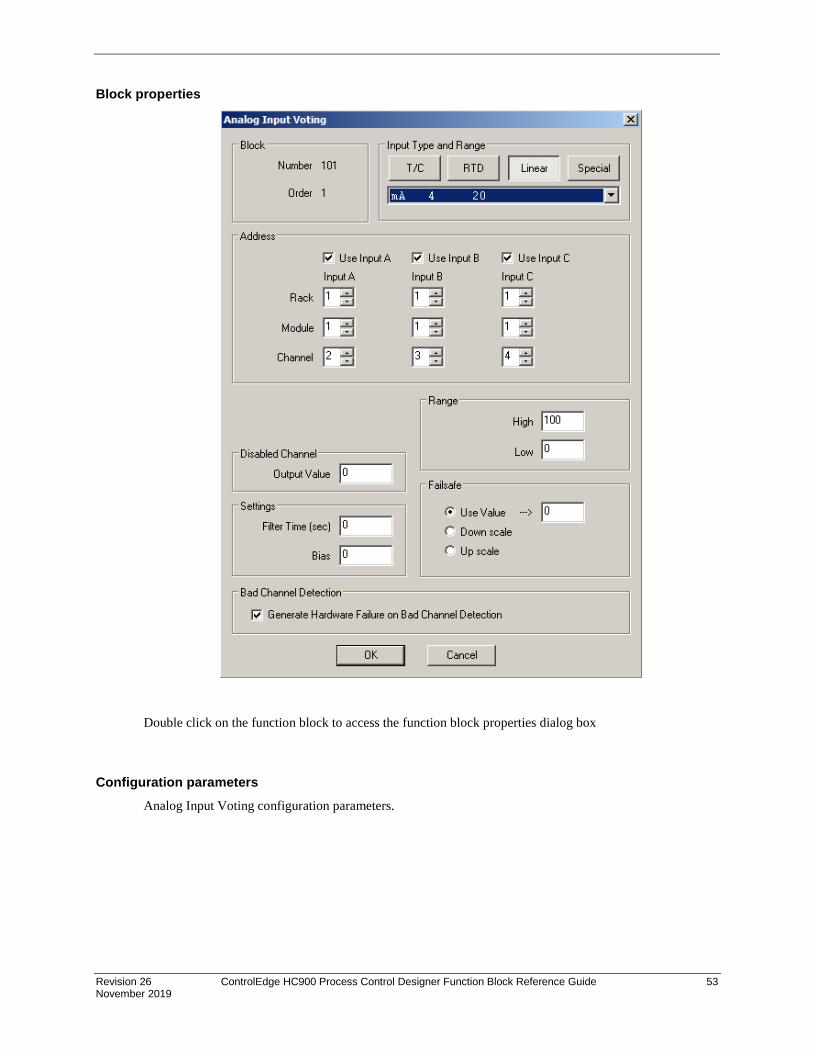
Revision 26 ControlEdge HC900 Process Control Designer Function Block Reference Guide 53 November 2019
Block properties
Double click on the function block to access the function block properties dialog box
Configuration parameters Analog Input Voting configuration parameters.

54 ControlEdge HC900 Process Control Designer Function Block Reference Guide Revision 26 November 2019
Properties Group
Parameter Index # Parameter Description Value or Selection
Block Order N/A Execution Order for Block
To change, See "Execution Order".
Read Only.
Address
Use Input A 4 Enable or Disable Input A Click on checkbox to select or deselect
Use Input B 5 Enable or Disable Input B Click on checkbox to select or deselect
Use Input C 6 Enable or Disable Input C Click on checkbox to select or deselect
Rack (for each Input)
N/A This is the address of the selected Rack.
Enter a value: from 1 to 5.
I/O Module (for each Input)
N/A Address of selected I/O module Enter a value: from 1 to 12
Channel (for each Input)
N/A Channel on selected I/O Module Enter a value: 1 to 16, depending on module type.
Input Type and Range
Input Type and Range
N/A Thermocouple, RTD, Linear Input types or Special Input Types - Carbon or Oxygen
Click on the "Input Type and Range" group button and select an input from list box.
Click Here for Input Types and Ranges
Range
High Range Value N/A For Linear Inputs Only - output value that corresponds to 100 % input value
For example: Actuation Input = 4-20mA
Process variable = Flow
Range of Flow = 0 to 250 gal/min
High Range Display Value = 250
Low range Display Value = 0
Then 20mA = 250, 4mA = 0
Enter a value:
- 99999 to 99999
Low Range Value N/A For Linear Inputs Only - output value that corresponds to 0 % input value
For example: See "High Range Value"
Enter a value:
-99999 to 99999
Disable Channel
Output Value 13 The output value when the AI channel is disabled. Disable = ON
Enter a value
Default = 0
Settings
Filter Time (sec) 7 A software digital filter is provided for the input designated to smooth the input. You can configure the first order lag time constant from 1 to 120 seconds.
0=no filter
Enter a value:
0 to 120 seconds

Revision 26 ControlEdge HC900 Process Control Designer Function Block Reference Guide 55 November 2019
Bias 8 Bias is used to compensate the input for drift of an input value due to deterioration of a sensor, or some other cause.
Enter a value:
-9999 to 99999
Failsafe
Use Value field N/A The output value to which the output will go to protect against the effects of failure of the equipment, such as, fuel shut-off if there is loss of flame in a furnace, or a sensor break.
Enter a value in Engineering Units
-9999 to 99999
Use Value N/A Use the value entered in the appropriate field.
Click on Radio button to select
Downscale N/A LINEAR
OUT = Value set at "Low range value" field.
T/C or RTD
OUT = Value of Low range implied by input type.
Click on Radio button to select
Upscale N/A LINEAR
OUT = Value set at "High range value" field.
T/C or RTD
OUT = Value of High range implied by input type.
Click on Radio button to select
Bad Channel Detection
Generate Hardware Failure on Bad Channel Detection
N/A Check this to generate a hardware failure diagnostic if a bad AI channel is detected. If unchecked, a diagnostic will not be generated, which may be desirable for inputs used for monitoring only.
Click on checkbox to select or deselect
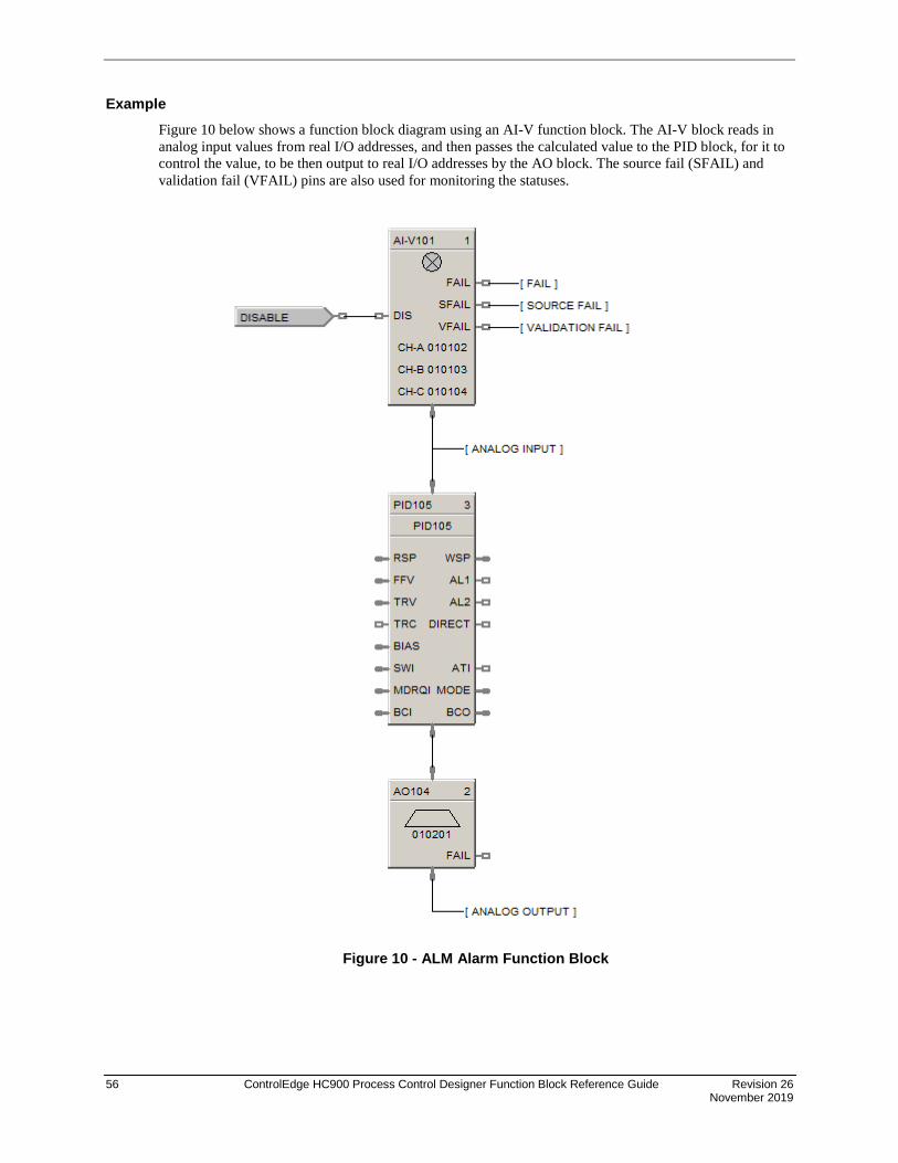
56 ControlEdge HC900 Process Control Designer Function Block Reference Guide Revision 26 November 2019
Example Figure 10 below shows a function block diagram using an AI-V function block. The AI-V block reads in analog input values from real I/O addresses, and then passes the calculated value to the PID block, for it to control the value, to be then output to real I/O addresses by the AO block. The source fail (SFAIL) and validation fail (VFAIL) pins are also used for monitoring the statuses.
Figure 10 - ALM Alarm Function Block

Revision 26 ControlEdge HC900 Process Control Designer Function Block Reference Guide 57 November 2019
Description The ALM label stands for the Analog Alarm function.
This block is part of the Alarms/Monitor category.
Function The analog alarm block accepts an analog signal as a process variable and compares it to a limit value (setpoint) to determine an alarm condition. The setpoint may be entered by the user or be another analog signal in the controller.
Alarm actions may be high, low or high deviation, low deviation or band deviation. For deviation alarming, a second analog signal provides the reference and setpoints represent deviation from the reference.
The alarm output may be inverted to create normally active digital output. A user selection for latching until acknowledged or automatically reset is provided.
A user-specified hysteresis value in the engineering units of the process variable is provided.
An on-delay time value up to 240 seconds is available to prevent momentary alarm actions. A digital reset input is available to disable alarm actions.
Note: If the alarm configured on output of this block and block is in safety sheet, alarm can’t be acknowledged in controller Run-Lock mode.
Alarm type function (PV>SP) High Process Variable/Local Setpoint
• OUT = ON If the PV is greater than the local Setpoint
• OUT = OFF If the PV is less than the Local Setpoint minus Hysteresis
(PV>CV) High Process Variable/Compare Value
• OUT = ON If the PV is greater than the Compare Value (CV) i.e. Alarm Setpoint
• OUT = OFF If the PV is less than the Compare Value minus Hysteresis
(PV<SP) Low Process Variable/Local Setpoint
• OUT = ON If the PV is less than the Local Setpoint
• OUT = OFF If the PV is greater than the Local Setpoint + Hysteresis
(PV<CV) Low Process Variable/Compare Value
• OUT = ON If the PV is less than the Compare Value (CV)
• OUT = OFF If the PV is greater than the Compare Value + Hysteresis

58 ControlEdge HC900 Process Control Designer Function Block Reference Guide Revision 26 November 2019
[(PV-CV)>SP] High Deviation Alarm
• OUT = ON If the PV input minus the CV input is greater than the Local Setpoint
• OUT = OFF If the PV input minus the CV input is less than the Local Setpoint minus Hysteresis
[(CV-PV)>SP] Low Deviation Alarm
• OUT = ON If the CV input minus the PV input is greater than the local Setpoint
• OUT = OFF If the CV input minus the PV input is less than the Local Setpoint minus Hysteresis
PV-CV>SP Band Deviation Alarm
• OUT = ON If the absolute value of (PV–CV) is greater than the Local Setpoint
• OUT = OFF If the absolute value of (PV–CV) is less than the Local Setpoint minus Hysteresis
Inputs PV = Process Variable CV = Compare Value RSP = Remote Setpoint DISABLE = On disables alarm action.
Output OUT = Output
Block properties
ATTENTION
Local Setpoint is set in the Process Control Designer unless “Use RSP Input” is enabled. Use an Analog Variable connected to one RSP input (use RSP Input Enabled) if you want to change alarm setpoint at the operator interface via the Variable Edit Display.

Revision 26 ControlEdge HC900 Process Control Designer Function Block Reference Guide 59 November 2019
Table 16 Analog alarm configuration parameters
Parameter Index #
Parameter Description Value or Selection
Block Order N/A Execution Order for Block Read Only. To change block order, right-click on a Function Block and select Execution Order.
Alarm Setpoint Type
N/A Alarm Action Type PV>SP = High Process Variable/Local Setpoint PV>CV = High Process Variable /Compare Value PV<SP = Low Process Variable/Local Setpoint PV<CV = Low Process Variable /Compare Value (PV-CV)>SP = High Deviation Alarm (CV-PV)>SP= Low Deviation Alarm IPV-CVI>SP = Band Absolute Deviation Alarm
Hysteresis 4 Hysteresis in engineering units can be set from 0 to the input span monitored variable.
0 to 99999.9 in Engineering Units
Local Setpoint
0 Local Setpoint value in engineering units or a calculation from another function block via RSP (see “Use RSP Input”).
0 to 99999.9 in Engineering Units
Use RSP Input
1 Remote Setpoint selection Click on box to use Remote Setpoint (RSP).
Output Latch
3 ON latches the alarm output until acknowledged. To acknowledge an alarm, it must be tagged and entered into an alarm group. This will provide for the acknowledgment from the operator interface.
Click on Box to select.
On Delay 6 Number of seconds the alarm is active before activating OUT.
0 to 240 seconds
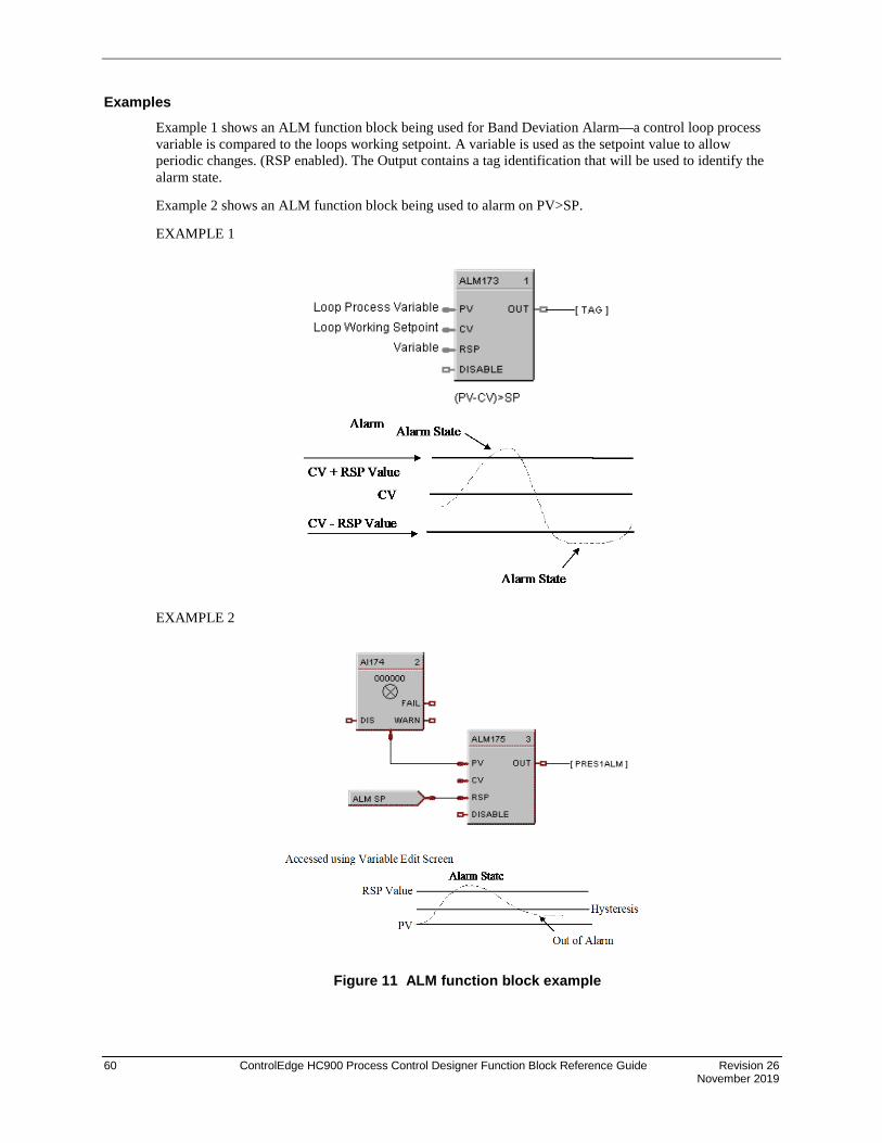
60 ControlEdge HC900 Process Control Designer Function Block Reference Guide Revision 26 November 2019
Examples Example 1 shows an ALM function block being used for Band Deviation Alarm—a control loop process variable is compared to the loops working setpoint. A variable is used as the setpoint value to allow periodic changes. (RSP enabled). The Output contains a tag identification that will be used to identify the alarm state.
Example 2 shows an ALM function block being used to alarm on PV>SP.
EXAMPLE 1
EXAMPLE 2
Figure 11 ALM function block example

Revision 26 ControlEdge HC900 Process Control Designer Function Block Reference Guide 61 November 2019
ALMGR Alarm Group Function Block
Description The ALMGR label stands for the Alarm Group function.
This block is part of the Alarms/Monitor category.
Function The Alarm Group Function Block allows you to tie alarm groups into the Control Strategy particularly when you do not have an Operator Interface. It provides remote acknowledgement of all alarms in the group.
This block is always stored in the reserved block area (40 thru 59), are always in the configuration whether visible in the FBD or not, and all outputs of the block are updates every alarm scan.
Input
ACK = acknowledges all alarms in group (rising edge). Clears UNACK.
Output
UNACK = ON when any of the alarms in the group have not been acknowledged.
ACTIV = ON when any of the alarms in the group are active.
Assign an Alarm Group
When you drag and drop an Alarm Group function block onto the worksheet, the "Assign Alarm Group" dialog box opens.
Select an Alarm Group (1 - 20) from the drop down menu, then click "OK". The function block will appear on the Function Block Diagram.
Configure an Alarm Group
1. Double-click on the Alarm Group function block. The Alarm Group Configuration dialog box will appear. The Group Number appears on the dialog box.
2. Digital signals will be displayed in the "Selected Tags" field.
3. Enter the group title. Use any mix of numbers, letters, and spaces.
4. Click on a Signal Tag name, then click on ADD. The selected signal tag will be placed in the next available position in the "Selected Tags" field, OR Select a position in the "Selected Tags" field, then click on INSERT. The selected signal tag will be placed in the position chosen in the "Selected Tags" field and the other signal tags will reorder as required.
5. Repeat the selection for up to 12 tags for each group.

62 ControlEdge HC900 Process Control Designer Function Block Reference Guide Revision 26 November 2019
6. Select a signal in the "Selected Tags" field and click on ALARM DETAILS, and enter Alarm details in the Dialog Box.
7. Click OK.
You can also select "Alarms" from: - the EDIT menu on the Process Control Designer Main Menus - The O/I Worksheet Toolbar button (when you have an O/I) - the FBD Worksheet toolbar button (when you do not have an O/I and do not need to use Alarm Group logic in the control strategy)
Example
Figure 12 ALMGR Function Block Example

Revision 26 ControlEdge HC900 Process Control Designer Function Block Reference Guide 63 November 2019
ALT Alternator Function Block
Description The ALT label stands for Alternator Function.
This block is part of the Auxiliary category.
Function The Alternator (ALT) function block is typically used to alternate the starting sequence of a group of pumps, valves, filters, etc. Each block accepts up to 16 inputs and controls up to 16 outputs.
There are four unique alternation styles used to control the output starting sequence so that you can limit the amount of repeat or continuous usage of a single device (pumps, valves, etc.). If an output device fails, or has been disabled, then an alternate device will be used in order to meet the requested demand. You may specify the alternators active outputs and the order in which the outputs are manipulated.
Each configuration is limited to a maximum of 6 Alternator function blocks.

64 ControlEdge HC900 Process Control Designer Function Block Reference Guide Revision 26 November 2019
Inputs IN1 – IN 16 =. Sixteen digital inputs for requesting an output device. Unconnected pins default to OFF.
DSBL = determines the status of the block:
OFF = Status of block is RUN - function blocks process normally - inputs and outputs reevaluated based on current states and style settings - the STI output pin is set to ON
ON = Status of block is OFF - function processes disabled, no input/output evaluation - all On and Off delay timers are reset - block’s style setting maintained - all outputs turned off - the STI output pin set to OFF.
^ADV = used with all styles except Direct. If “Activate Advance” selected in configuration, an OFF to ON transition will rotate the output order selection.
DRDYS = digital encoded device-ready signal, usually the bit encoded output of the Digital Encoder Block (DENC) representing 16 digital states. No signal = 0 Bit 1 = OUT 1, Bit 16 = OUT 16 Example: If bit 3 is ON, "OUT 3" is enabled and its state can turn On/Off based on the Alternator Sequence. If bit 3 is OFF, "OUT 3" is disabled. Out 3's state will change to OFF.
Outputs OUT1 – OUT16 =. Sixteen digital outputs, which turn ON and OFF based on the input demand [IN1-16]. Outputs can be manually disabled by way of the Outputs tab in the block properties. Outputs can be programmatically disabled by the use of the "DRDYS" input pin.
ODIS = ON when any one of the outputs (OUT) is manually disabled, otherwise OFF
IDIS = ON when any one of the inputs (IN) is manually disabled, otherwise OFF
STI = ON when the block state is RUN; OFF when the block state is OFF.
Configurable Parameters The Alternator properties dialog box is divided into four tab cards:
GENERAL INPUTS OUTPUTS SEQUENCE ORDER
Click on the tab to access the properties for that tab.

Revision 26 ControlEdge HC900 Process Control Designer Function Block Reference Guide 65 November 2019
GENERAL tab
Style selections A style is a method used to control the cycling of the 16 outputs. There are four styles from which to choose: Direct, Rotary (Last ON/First OFF), First ON/First OFF (FOFO), or Fixed (with Advance feature). This parameter is initially configured here and can be altered from an operator interface.
Important: A style change request does not take effect until all inputs (IN1 - 16) are OFF.
DIRECT Monitors up to 16 inputs and maps them, using the user adjustable map order on the Output tab, directly to the outputs. If the Inputs selected are 1, 2, 3, 4, 5, 6 and the Output order mapped is 6, 3, 4, 1, 5, 2; when Input 3 is activated, Output 4 is enabled; or if Input 1 is activated then Output 6 is enabled.
ROTARY Uses the sum of the 16 inputs that are set to ON to determine the required demand for outputs. The output order is managed in a Last ON/First OFF basis (LOFO). If the Inputs selected are 1, 2, 3 and the mapped sequence is 1, 2, 3 the alternator sequence changes when NO outputs (pumps) are required or there is a request to Advance (see Activate Advance). Depending on the capacity required, Outputs 1, 2, 3 come on in order. When the demand falls, Output 3 goes OFF, then Output 2, then Output 1. When Output 1 turns off, the Rotary sequence advances and Output 2 starts the next cycle. If an input pin is set to “not available”, then that output is forced to OFF and the next available output in the mapping order is turned ON. If the previously bypassed output later becomes enabled, then it will not be used until the demand increases.

66 ControlEdge HC900 Process Control Designer Function Block Reference Guide Revision 26 November 2019
FOFO Uses the sum of the 16 inputs that are set to ON to determine the required demand for outputs. The output order is managed in a First ON/First OFF basis (FOFO). If 3 Inputs are ON (no mapping), the Alternator sequence changes (first one in the list moves to the end of the list) as the inputs turn OFF or, when there is a request for Advance (see Activate Advance). If an input pin is set to “not available”, then that output is forced to OFF and the next available output is turned ON. If the previously bypassed output later becomes enabled, then it will not be used until the demand increases.
FIXED Uses the sum of the 16 inputs that are set to ON to determine the required demand for outputs. The output order is managed in a First ON/First OFF basis (FOFO). If the Inputs selected are 1, 2, 3, 4 and you map a fixed sequence 4, 2, 3, 1 the sequence will not change unless you select the Advance feature (see Activate Advance). It takes a direct command (OFF to ON signal) before the output order map rotates to the 2, 3, 1, 4 sequence. If an output pin is not available then that output is forced OFF and the next available output in the mapping order is turned ON. If the previously bypassed output later becomes enabled, then it will not be used until the demand increases.
Activate advance Used with all styles except Direct. If you select “Activate Advance” (click on box on General tab to select), an OFF to ON transition of the ^ADV Input pin will rotate the output order sequence. Make before Break selection determines how this is done for Rotary and FOFO only.
Make before break This feature works on input demand and with the Advance input, it is available for Fixed, Rotary and FOFO styles.
When the ALT function block receives an Advance input (^ADV pin) and Make before Break is selected (click on box on General tab to select) the next output in the sequence is activated before deactivating an output. When the selection box on the General tab is not selected (Break before Make) the output is removed before advancing the sequence and activating the next output. The ON and OFF Delay Timers are used with this feature. See next figure.
OFF
Delay
ON
Delay
ON
Delay
ON
Delay
OFF
Delay
ON
Delay
OFF
Delay
ON
OFF
ON
OFF
ON
OFF
ON
OFF
OUTPUT 1
OUTPUT 2
OUTPUT 3
OUTPUT 4
2 outputsrequested
Advanceoccurs andMBB* is set
Advanceoccurs and
BBM** is set
* MBB - Make before Break** BBM - Break before Make*** When an output is in use and it becomes disabled or fails, the
BBM feature is used to turn on the next available output
2 outputsrequestedand one of
them isdisabled
(or fails)***
3 outputsrequestdwith #3
output stilldisabled
initiallyno outputsrequested
ON
Delay
ON
Delay

Revision 26 ControlEdge HC900 Process Control Designer Function Block Reference Guide 67 November 2019
ON/OFF delay timers There is an On-delay timer and Off-delay timer value that applies to all 16 outputs. These timers are the same times used with the Make/Break feature. There is one period for all On-delay times and one period for all Off-delay times.
If an output is waiting in an On-delay timer and new input conditions the output state to turn OFF, then the delay timer is reset, the output does not change state. If an output is waiting in an Off-delay timer and new input conditions the output state to turn ON, then the delay timer is reset, the output does not change state.
The timers operate in a cascade style. Example: If three outputs are requested, output #1 Turns On, then #2 which is followed by #3.
Table 17 ALT general tab parameters
Properties Group Parameter Index # Parameter Description Value or Selection
General Tag Name N/A 16-character tag name (ASCII characters only)
Descriptor N/A Block description
Time Delay On-Time Delay (seconds)
1 Delay time used before turning ON the next output in the sequence. Used with “Make/Break” feature See “ON/OFF Delay Timers”
Range: 0 – 99999 sec Default = 0
Value can be changed from the Operator Interface
Off-Time Delay (seconds)
2 Delay time used before turning OFF the next output in the sequence. Used with “Make/Break” feature See “ON/OFF Delay Timers”
Range: 0 – 99999 sec Default = 0
Value can be changed from the Operator Interface
Styles Direct N/A
See “Style Selections” for definitions
DIRECT ROTARY FOFO FIXED The parameter selected here can be altered from an operator interface.
Rotary
FOFO
Fixed
Make before Break
3 Determines how an OUT is toggled ON and OFF. Used with “Rotary” and “FOFO” styles See “Make before Break” for definition.
ON = Make before Break OFF = Break before Make
Default = Make before Break
Activate Advance
Used with all styles except Direct
0 Activates the “Advance” feature. This allows an OFF to ON transition of the ^ADV Input pin to rotate the output order sequence. See “Activate Advance” for definition.
Click on box to turn ON Activate Advance
The parameter selected here cannot be altered from an operator interface

68 ControlEdge HC900 Process Control Designer Function Block Reference Guide Revision 26 November 2019
INPUT tab Click on the “Enable Input” block to activate that particular Input [1 – 16], deselect to inactivate it. “Enable” is the default. (Indices 6 thru 21)
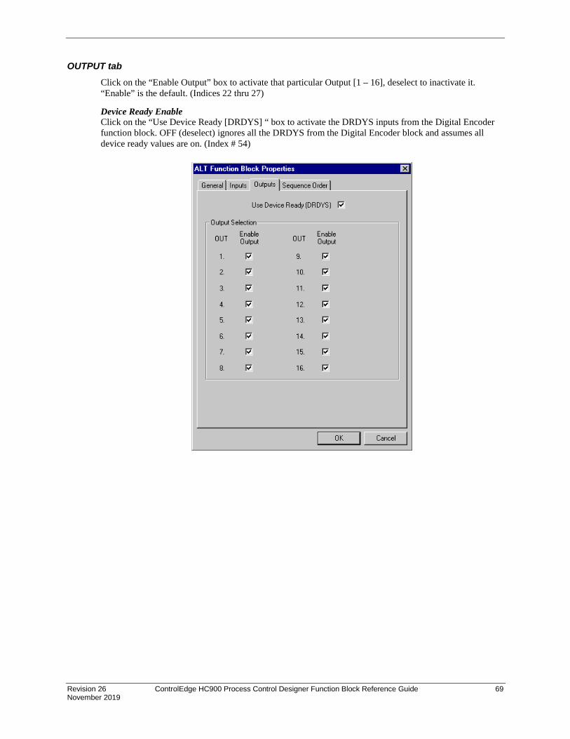
Revision 26 ControlEdge HC900 Process Control Designer Function Block Reference Guide 69 November 2019
OUTPUT tab Click on the “Enable Output” box to activate that particular Output [1 – 16], deselect to inactivate it. “Enable” is the default. (Indices 22 thru 27)
Device Ready Enable Click on the “Use Device Ready [DRDYS] “ box to activate the DRDYS inputs from the Digital Encoder function block. OFF (deselect) ignores all the DRDYS from the Digital Encoder block and assumes all device ready values are on. (Index # 54)

70 ControlEdge HC900 Process Control Designer Function Block Reference Guide Revision 26 November 2019
Direct Style selected Rotary, FOFO, or Fixed Style selected
Table 18 ALT sequence tab parameters
Sequence Number
Parameter Field
Action Selections Comments
1 Maximum Outputs used
Use the scroll buttons in the active field and select the number of outputs to be used.
1 to16 Selecting less than 16 Outputs will make the unused Outputs in the “Output Selection” column = 0 after “OK” is selected.
2
Edit Sequence Order
Click on the “Edit Sequence Order” button to activate the Sequence Order dialog box.
Click, Drag, and release any output to any order, as shown to the left, to select the sequence in which the outputs will be turned on.
Click “OK”.
Sequence Order Default = OUT1, OUT2, OUT3 : : OUT15, OUT16.
May be changed by a special message.

Revision 26 ControlEdge HC900 Process Control Designer Function Block Reference Guide 71 November 2019
Example Figure 13 shows a function block diagram using an ALT function block.
Figure 13 ALT function block example

72 ControlEdge HC900 Process Control Designer Function Block Reference Guide Revision 26 November 2019
AMB Auto/Manual Bias Function Block
Description The AMB label stands for Auto/Manual Bias Function.
This block is part of the Loops category.
Function On transfer from Manual to Auto; Bias is calculated to make PV + Bias = Output.
Inputs PV1 = Process Variable Input (%)
TRV = Output Track Value in percentage (Output = TRV Value when TRC is ON).
TRC = Output Track Command—1 = enable TRV (Mode = Local Override), 0 = disable
MDRQI = External Mode Request (connected to the MDRQO output of a MDSW function block) encoded as follows: 0.0 = No Change 1.0 = Manual Mode Request 2.0 = Automatic Mode Request
Outputs OUT = Control Output (–5 % to 105 %)
AL1 = Alarm 1
AL2 = Alarm 2
MODE = Actual Mode encoded as follows: (Connect to Mode Flags block [MDFL] to encode mode status.) 4.0 LSP AUTO 5.0 LSP MAN 7.0 LSP LO (Local Override)
Configuration parameters The Auto/Manual Bias properties dialog box is divided into four tab cards
GENERAL START/RESTART RANGE/LIMIT ALARMS
Click on the tab to access the properties for that tab.

Revision 26 ControlEdge HC900 Process Control Designer Function Block Reference Guide 73 November 2019
GENERAL tab
Table 19 AMB General tab configuration parameters
Parameter Index # Parameter Description Value or Selection
Block Tag Name
N/A 16-character tag name (ASCII characters only)
Block Descriptor
N/A Block description

74 ControlEdge HC900 Process Control Designer Function Block Reference Guide Revision 26 November 2019
Start/Restart tab
Table 20 AMB Start Restart tab configuration parameters
Parameter Index # Parameter Description Value or Selection
Permitted Mode
N/A Mode permitted for the initial start and power up mode.
MAN Manual
AUTO Automatic
Initial Mode N/A Mode at NEWSTART
Newstart is the first scan cycle following the cold start of the controller
MAN Manual
AUTO Automatic
Power up Mode
N/A Mode at power up MAN Manual
PREVIOUS Same mode (auto or manual)
Power Up Out
N/A Output at Power up FAILSAFE Failsafe output value.
LAST OUT Same as at power down.
Failsafe Out 9 Failsafe Output Value –5 to 105 (default 0)

Revision 26 ControlEdge HC900 Process Control Designer Function Block Reference Guide 75 November 2019
RANGE/LIMIT tab
Table 21 AMB Range/limit tab configuration parameters
Parameter Index # Parameter Description Value or Selection
PV High Range 0 PV High Range Value –5 % to 105 %
PV Low Range 1 PV Low Range Value –5 % to 105 %
Display Decimal Places N/A Number of digits to display after decimal point.
0 to 5
Out High Limit 7 Output High Limit Value - prevents the Output from going above the value set here.
–5 % to 105 %
Out Low Limit 8 Output Low Limit Value - prevents the Output from going below the value set here.
–5 % to 105 %

76 ControlEdge HC900 Process Control Designer Function Block Reference Guide Revision 26 November 2019
ALARMS tab
Table 22 AMB Alarm tab configuration parameters
Parameter Index # Parameter Description Value or Selection
Alarm 1 Setpoint 1
10 Alarm 1 Setpoint 1 Value - this is the value at which you want the alarm type chose below to activate
–5 % to +105 %
(default 0)
Alarm 1 Type N/A Alarm 1 Setpoint 1 Type - select what you want Alarm 1 Setpoint 1 to represent.
Selections: NO ALARM AL_PV_HI AL_PV_LO AL_OUT_HI AL_OUT_LO
Alarm 1 Setpoint 2
11 Alarm 1 Setpoint 2 Value Same as Alarm 1 Setpoint 1
Alarm 1 Type N/A Alarm 1 Setpoint 2 Type Same as Alarm 1 Setpoint 1
Alarm 2 Setpoint 1
12 Alarm 2 Setpoint 1 Value Same as Alarm 1 Setpoint 1
Alarm 2 Type N/A Alarm 2 Setpoint 1 Type Same as Alarm 1 Setpoint 1
Alarm 2 Setpoint 2
13 Alarm 2 Setpoint 2 Value Same as Alarm 1 Setpoint 1
Alarm 2Type N/A Alarm 2 Setpoint 2 Type Same as Alarm 1 Setpoint 1
Alarm Hysteresis %
18 Alarm Hysteresis in % 0 % to 5 %
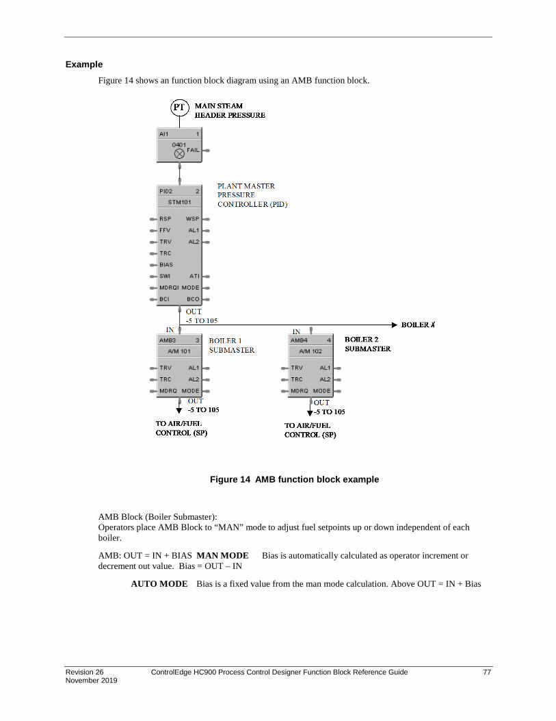
Revision 26 ControlEdge HC900 Process Control Designer Function Block Reference Guide 77 November 2019
Example Figure 14 shows an function block diagram using an AMB function block.
Figure 14 AMB function block example
AMB Block (Boiler Submaster): Operators place AMB Block to “MAN” mode to adjust fuel setpoints up or down independent of each boiler.
AMB: OUT = IN + BIAS MAN MODE Bias is automatically calculated as operator increment or decrement out value. Bias = OUT – IN
AUTO MODE Bias is a fixed value from the man mode calculation. Above OUT = IN + Bias
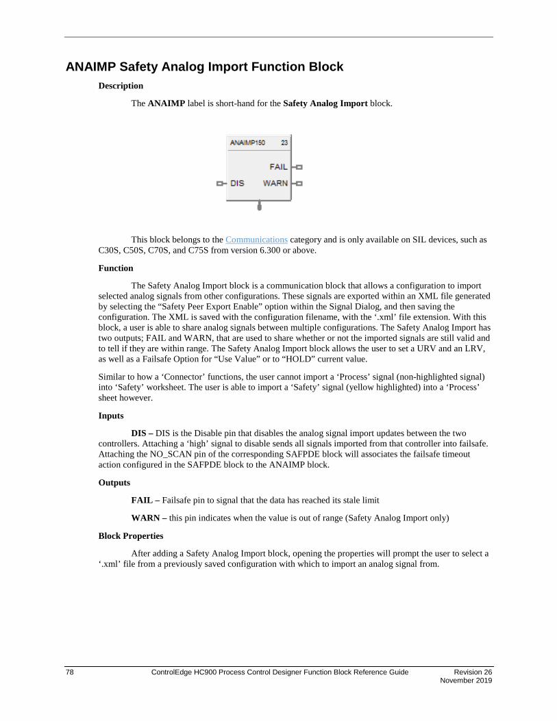
78 ControlEdge HC900 Process Control Designer Function Block Reference Guide Revision 26 November 2019
ANAIMP Safety Analog Import Function Block Description
The ANAIMP label is short-hand for the Safety Analog Import block.
This block belongs to the Communications category and is only available on SIL devices, such as C30S, C50S, C70S, and C75S from version 6.300 or above.
Function
The Safety Analog Import block is a communication block that allows a configuration to import selected analog signals from other configurations. These signals are exported within an XML file generated by selecting the “Safety Peer Export Enable” option within the Signal Dialog, and then saving the configuration. The XML is saved with the configuration filename, with the ‘.xml’ file extension. With this block, a user is able to share analog signals between multiple configurations. The Safety Analog Import has two outputs; FAIL and WARN, that are used to share whether or not the imported signals are still valid and to tell if they are within range. The Safety Analog Import block allows the user to set a URV and an LRV, as well as a Failsafe Option for “Use Value” or to “HOLD” current value.
Similar to how a ‘Connector’ functions, the user cannot import a ‘Process’ signal (non-highlighted signal) into ‘Safety’ worksheet. The user is able to import a ‘Safety’ signal (yellow highlighted) into a ‘Process’ sheet however.
Inputs
DIS – DIS is the Disable pin that disables the analog signal import updates between the two controllers. Attaching a ‘high’ signal to disable sends all signals imported from that controller into failsafe. Attaching the NO_SCAN pin of the corresponding SAFPDE block will associates the failsafe timeout action configured in the SAFPDE block to the ANAIMP block.
Outputs
FAIL – Failsafe pin to signal that the data has reached its stale limit
WARN – this pin indicates when the value is out of range (Safety Analog Import only)
Block Properties
After adding a Safety Analog Import block, opening the properties will prompt the user to select a ‘.xml’ file from a previously saved configuration with which to import an analog signal from.

Revision 26 ControlEdge HC900 Process Control Designer Function Block Reference Guide 79 November 2019
The above image shows several XML files that are automatically generated after saving a configuration.
After selecting the ‘.xml’ file, the following screen is shown to allow the user to select the analog signal to import:

80 ControlEdge HC900 Process Control Designer Function Block Reference Guide Revision 26 November 2019
The Safety Analog Import have a ‘Signal Tag’, ‘Description’, ‘Type’, external signal ‘Number’, ‘Units’ and ‘Decimals’.
Once a signal is selected, and ‘OK’ is pressed, the block will hold the information from the previous dialog, as shown below:
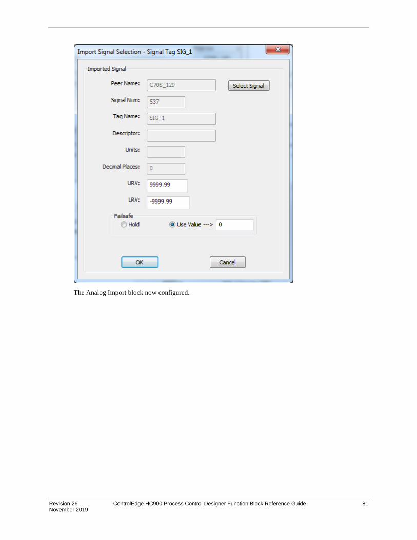
Revision 26 ControlEdge HC900 Process Control Designer Function Block Reference Guide 81 November 2019
The Analog Import block now configured.

82 ControlEdge HC900 Process Control Designer Function Block Reference Guide Revision 26 November 2019
Configuration Parameters
In the properties page, the user is able to configure the URV and LRV for the block, as well as the Failsafe option. The Safety Analog Import block allows either the last known good value to be held, or will output a pre-selected value if ‘Use Value->’ is chosen.
Parameter Index # Parameter Description
Value Or Selection
Default
URV N/A Upper range value
-99999 to 99999 9999.99
LRV N/A Lower range value
-99999 to 99999 -9999.99
Failsafe N/A Action to be taken when the block goes to fail.
Hold – output will hold to last good value
Use Value – output will go to this specified value
Click on radio button to select
Any float 32 bit value
Use Value = 0
Related Function Blocks
SAFPDE – Safety Peer Monitor block
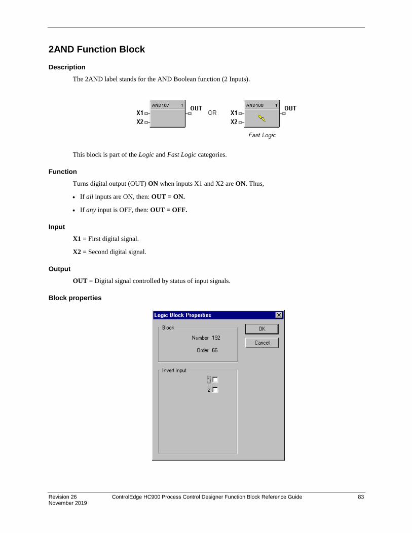
Revision 26 ControlEdge HC900 Process Control Designer Function Block Reference Guide 83 November 2019
2AND Function Block
Description The 2AND label stands for the AND Boolean function (2 Inputs).
This block is part of the Logic and Fast Logic categories.
Function Turns digital output (OUT) ON when inputs X1 and X2 are ON. Thus,
• If all inputs are ON, then: OUT = ON.
• If any input is OFF, then: OUT = OFF.
Input X1 = First digital signal.
X2 = Second digital signal.
Output OUT = Digital signal controlled by status of input signals.
Block properties
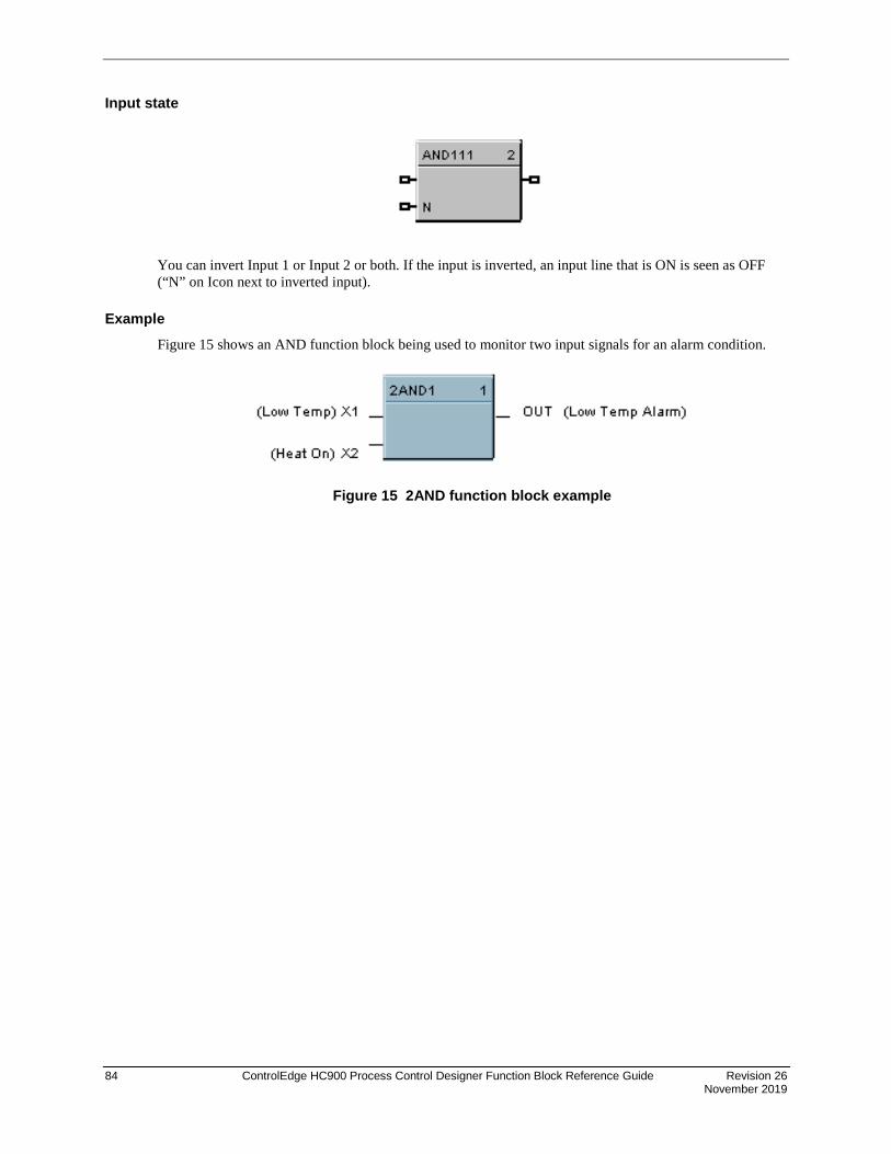
84 ControlEdge HC900 Process Control Designer Function Block Reference Guide Revision 26 November 2019
Input state
You can invert Input 1 or Input 2 or both. If the input is inverted, an input line that is ON is seen as OFF (“N” on Icon next to inverted input).
Example Figure 15 shows an AND function block being used to monitor two input signals for an alarm condition.
Figure 15 2AND function block example

Revision 26 ControlEdge HC900 Process Control Designer Function Block Reference Guide 85 November 2019
4ALM Function Block
Description The 4ALM label stands for the 4 Alarm with Hysteresis.
This block is part of the Alarm/Monitor Blocks category.
Function This block monitors four analog input values (SP1, SP2, SP3, SP4) and performs up to four alarm comparisons against the PV input. Configurable Alarm types are Disabled, Low, High. The associated output pins, AL1 through AL4, will turn ON if the configured HIGH or LOW alarm condition is present. The individual hysteresis settings for each alarm are used to prevent output cycling.
Inputs PV = Process variable
SP1 = Analog value
SP2 = Analog value
SP3 = Analog value
SP4 = Analog value
Outputs AL1 = Alarm output
AL2 = Alarm output
AL3 = Alarm output
AL4 = Alarm output

86 ControlEdge HC900 Process Control Designer Function Block Reference Guide Revision 26 November 2019
Configurable parameters Parameter Index # Parameter Description Value or Selection
Block Order N/A Execution Order for Block Read Only. To change block order, right-click on a Function Block and select Execution Order.
Tag Name n/a 16-character tag name (ASCII characters only)
Descriptor n/a Block description Alarm type 0-3 Alarm type Disabled, Low, High Hysteresis 4-7 Adjustable overlap of the on/off
states of the output. 0 to the span of the input in engineering units.
Example Use the Four Alarm function block to configure up to four alarm setpoints (Low/Low, Low -- High, High/High) for a single input signal.
Figure 16 4ALM function block example

Revision 26 ControlEdge HC900 Process Control Designer Function Block Reference Guide 87 November 2019
4AND Function Block
Description The 4AND label stands for the AND Boolean function (4 Inputs).
This block is part of the Logic and Fast Logic categories.
Function Turns digital output (OUT) ON when inputs X1 through X4 are ON. Thus,
• If all inputs are ON, then: OUT = ON.
• If any input is OFF, then: OUT = OFF.
Input X1 = First digital signal X2 = Second digital signal X3 = Third digital signal X4 = Fourth digital signal
ATTENTION
Unused values must be set to 1 or inverted.
Output OUT = Digital signal controlled by status of input signals
Block properties
Double click on the function block to access the function block properties dialog box.
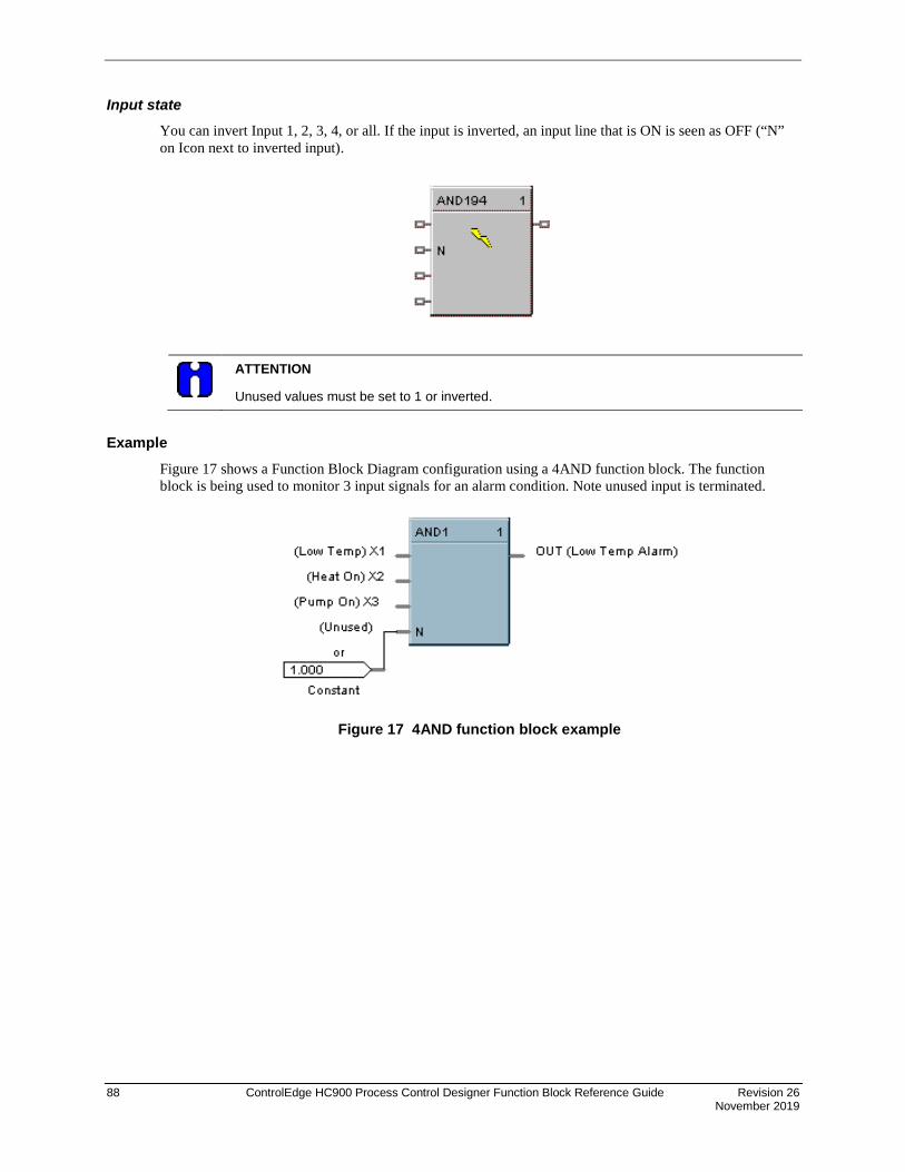
88 ControlEdge HC900 Process Control Designer Function Block Reference Guide Revision 26 November 2019
Input state You can invert Input 1, 2, 3, 4, or all. If the input is inverted, an input line that is ON is seen as OFF (“N” on Icon next to inverted input).
ATTENTION
Unused values must be set to 1 or inverted.
Example Figure 17 shows a Function Block Diagram configuration using a 4AND function block. The function block is being used to monitor 3 input signals for an alarm condition. Note unused input is terminated.
Figure 17 4AND function block example

Revision 26 ControlEdge HC900 Process Control Designer Function Block Reference Guide 89 November 2019
8AND Function Block
Description The 8AND label stands for the AND Boolean function (8 Inputs).
This block is part of the Logic and Fast Logic categories.
Function Turns digital output (OUT) ON when inputs X1 through X8 are ON. Thus,
• If all inputs are ON, then: OUT = ON.
• If any input is OFF, then: OUT = OFF.
Input X1 = First digital signal X2 = Second digital signal X3 = Third digital signal X4 = Fourth digital signal X5 = Fifth digital signal X6 = Sixth digital signal X7 = Seventh digital signal X8 = Eighth digital signal
ATTENTION
Unused values must be set to 1 or inverted.
Output OUT = Digital signal controlled by status of input signals.
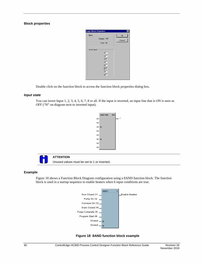
90 ControlEdge HC900 Process Control Designer Function Block Reference Guide Revision 26 November 2019
Block properties
Double click on the function block to access the function block properties dialog box.
Input state
You can invert Input 1, 2, 3, 4, 5, 6, 7, 8 or all. If the input is inverted, an input line that is ON is seen as OFF (“N” on diagram next to inverted input).
ATTENTION Unused values must be set to 1 or inverted.
Example Figure 18 shows a Function Block Diagram configuration using a 8AND function block. The function block is used in a startup sequence to enable heaters when 6 input conditions are true.
Figure 18 8AND function block example

Revision 26 ControlEdge HC900 Process Control Designer Function Block Reference Guide 91 November 2019
AO Function Block
Description The AO label stands for a milliamp Analog Output.
This block is part of the I/O Blocks category.
Function Range High and Range Low are used to specify the Engineering Unit values for 100 % and 0 % of this block’s input span. For reverse outputs, Range High may be set to a value less than Range Low.
The output range high and range low values (0-20 maximum) set the milliamp output values that correspond to the 0 % to 100 % span limits of the inputs.
Input IN = Analog value
Output OUT = Converted value sent to specified real I/O address.
FAIL = Failed Output indication - Module Error. 8 and 16 channel analog outputs require loop power open for loop detection.
Block properties
Double click on the function block to access the function block properties dialog box.

92 ControlEdge HC900 Process Control Designer Function Block Reference Guide Revision 26 November 2019
Configuration parameters AO’s Address starts at Module 4.
Table 23 Analog output configuration parameters
Properties Group Parameter Index # Parameter Description Value or Selection Block Order N/A Execution Order for Block Read Only. To change
block order, right-click on a Function Block and select Execution Order.
Address Rack This is the address of the selected Rack.
Enter a value from 1 to 5.
I/O Module Address of selected I/O module Enter a value: from 1 to 12
Channel Channel on selected I/O Module Enter a value: from 1 to 16
Range Range Hi 1 High Range Value Engineering Unit - value of input that corresponds to 100 % output value
-99999 to 999999 Default = 100
Range Low 2 Low Range Value Engineering Unit - value of input that corresponds to 0 % output value
-99999 to 999999 Default = 0.0
Output mA at range High
3 Value of mA output that corresponds to 100 % output signal (for example: 20 mA)
0 to 20 Default = 20
mA at Low Range
4 Value of mA output that corresponds to 0 % output signal (for example: 4 mA)
0 to 20 Default = 4
Output Limits mA at range High Limit
N/A Value of mA that you want to set the High Range Limit
0 to 21 Default = 21
mA at Low Range Limit
N/A Value of mA that you want to set the Low Range Limit
0 to 21 Default = 0
Failsafe Failsafe Value
N/A Failsafe Value 0 to 21 mA Default = 0
Failsafe Type
8 Type of Failsafe High - sets the output of the block to High Output Range limit when failure is detected Low - sets the output of the block to Low Output Range Limit when failure is detected Hold - hold the output at the last value just prior to the failure being detected
Slew Rate Slew Time in seconds
9 Slew Rate is the maximum rate of change required to drive the output from full OFF (0% - typically 4 mA) to full ON (100% - typically 20mA). The block will convert this to a maximum change of the milliamp output per execution cycle of the block.
Enter a value of from 0.0 to 99

Revision 26 ControlEdge HC900 Process Control Designer Function Block Reference Guide 93 November 2019
Example Figure 19 shows a Function Block Diagram configuration using an AO function block to retransmit an analog input value. In example A, the output is from a SPP block to an external controller via the AO block. In example B, the mA output is 4 mA for an analog input of 2000.
ATTENTION
Reverse scaling is required for duplex control outputs.
Figure 19 AO function block example

94 ControlEdge HC900 Process Control Designer Function Block Reference Guide Revision 26 November 2019
Analog Output Validated
Description The AO-V label stands for Analog Output Validated . This block is part of the I/O Blocks category.
Function Provides an analog output from the algorithms and functions to physical analog output hardware. The analog status is fed back to AI feedback channel for validation. Each AO-V block and feedback AI requires a module and channel number during configuration.
NOTE: For calibration of AI channel, please follow following steps
1. Create a configuration using AO-V function block and configure the address of feedback input same as the AI channel which is to be calibrated.
2. Download the configuration to controller.
3. Now follow the steps given "Calibrate AI Channel " section.
Input X = Input Analog Signal
^RSTRT = Restart Signal – When used, a positive (rising) input pulse releases OUT from its failsafe value and FAIL pin from its ON state. If ^RSTRT pin is left unconnected, the function block’s OUT and FAIL pins will not latch the status. This allows for the replacement or repair of the failed AO module or failure condition and operator controlled release.
DIS = Disable Signal – When used and made ON, disables the AO Channel and also results in disabling of ^RSTRT functionality. If DIS pin left unconnected or made OFF, results in Normal Operation i.e. it enables the function block.
Output OUT = Physical output value of function block
FAIL = Failed Output Indication – AO module has an error. OUT is set to failsafe (0 - for safety worksheet and option-selectable for process worksheet).
FBFAIL = Feedback Fail – Feedback AI module fail. OUT continues to function without feedback validation.
VFAIL = Validation Fail – Input does not match output status i.e. the value read does not equal the value written. The percent deviation allowed from input to output is +/- 3% i.e. if the input to output is outside of +/- 3 %, VFAIL will be ON. Please note that percent deviation is calculated based out of output range. If AI module has an error, VFAIL will stay OFF. OUT continues to function without feedback validation.

Revision 26 ControlEdge HC900 Process Control Designer Function Block Reference Guide 95 November 2019
Block properties
Double click on the function block to access the function block properties dialog box

96 ControlEdge HC900 Process Control Designer Function Block Reference Guide Revision 26 November 2019
Configuration parameters Analog output validated configuration parameters
Properties Group Parameter Index # Parameter Description Value or Selection
Address
Rack
N/A
Rack address of selected DO module From 1 to 12
I/O Module Address of selected DO module From 1 to 12
Channel Channel number on selected DO module
From 1 to 32, depending on the physical module type – DC or AC or Relay
Input Range
Range High 1
High Range Value Engineering Unit - value of input that corresponds to 100 % output value
99999 to 999999
Default = 100
Range Low 2
Low Range Value Engineering Unit - value of input that corresponds to 0 % output value
99999 to 999999
Default = 0.0
Output Range
mA at range High
3
Value of mA output that corresponds to 100 % output signal (for example: 20 mA)
0 to 20
Default = 20
mA at Range Low
4
Value of mA output that corresponds to 0 % output signal (for example: 4 mA)
0 to 21
Default = 21
Output Limits
mA at High Limit
N/A Value of mA that you want to
set the High Range Limit
0 to 20
Default = 20
mA at Low Limit
N/A Value of mA that you want to
set the Low Range Limit
0 to 21
Default = 21

Revision 26 ControlEdge HC900 Process Control Designer Function Block Reference Guide 97 November 2019
Failsafe
Value N/A USE VALUE sets the output to the programmed value when failure is detected.
0 to 21 mA
Default = 0
Failsafe Type N/A Type of Failsafe
High - sets the output of the block to the High Output Range Value when failure is detected
Low - sets the output of the block to the Low Output Range Value when failure is detected
Hold - maintains the last value of the block just prior to the failure being detected
Slew Rate Slew Rate in Seconds 9
Slew Rate is the maximum rate of change required to drive the output from full OFF (0% - typically 4 mA) to full ON (100% - typically 20mA). The block will convert this to a maximum change of the milliamp output per execution cycle of the block.
0.0 to 99
Address
Rack
N/A
Rack address of selected feedback AI module From 1 to 12
I/O Module Address of the selected feedback AI module From 1 to 12
Channel Channel number on the selected feedback AI module From 1 to 32
Input Shunt Input Shunt in Ohms N/A Value of input shunt
62.5 Ω
100 Ω
250 Ω
500 Ω

98 ControlEdge HC900 Process Control Designer Function Block Reference Guide Revision 26 November 2019
Example Figure below shows a function block diagram using a AO-V function block. An analog output signal from PID block will control the analog output for AO-V block output for monitoring. The feedback fail (FBFAIL) and validation fail (VFAIL) are also used for monitoring the statuses. The connection to “RSTRT” pin ensures that the status on OUT and FAIL pins will remain latched, until a positive (rising) edge is detected on “RSTRT” pin.

Revision 26 ControlEdge HC900 Process Control Designer Function Block Reference Guide 99 November 2019
ASYS Analog System Status Function Block
Description The ASYS label stands for Analog System Status. This block is part of the Alarm/Monitor Blocks category.
Function This function block provides read access to controller status values including those related to the Normal Scan execution cycle. (To access status values associated with the Fast Scan execution cycle see the FSYS function block.) The outputs may be connected to the function block inputs. The outputs may also be connected to signal tags for operator interface monitoring. The Analog System Status block is assigned block number 1.
Versions The status information available to be monitored for the analog system depends on both the controller type and the revision of software executing on the controller. As a result, there are different versions of the ASYS block and when you drag and drop this block onto a configuration worksheet the graphic may look a little different than the one shown above. The Process Control Designer will automatically select the correct version of the block based on the controller type and software revision selected for each configuration file.
The graphic shown above is for the most advanced version of the block and earlier versions may have fewer outputs, different output types and/or different output ordering. Where applicable, the differences are described in the table below for each output.
Restrictions There can be only one instance of the ASYS function block within a configuration.
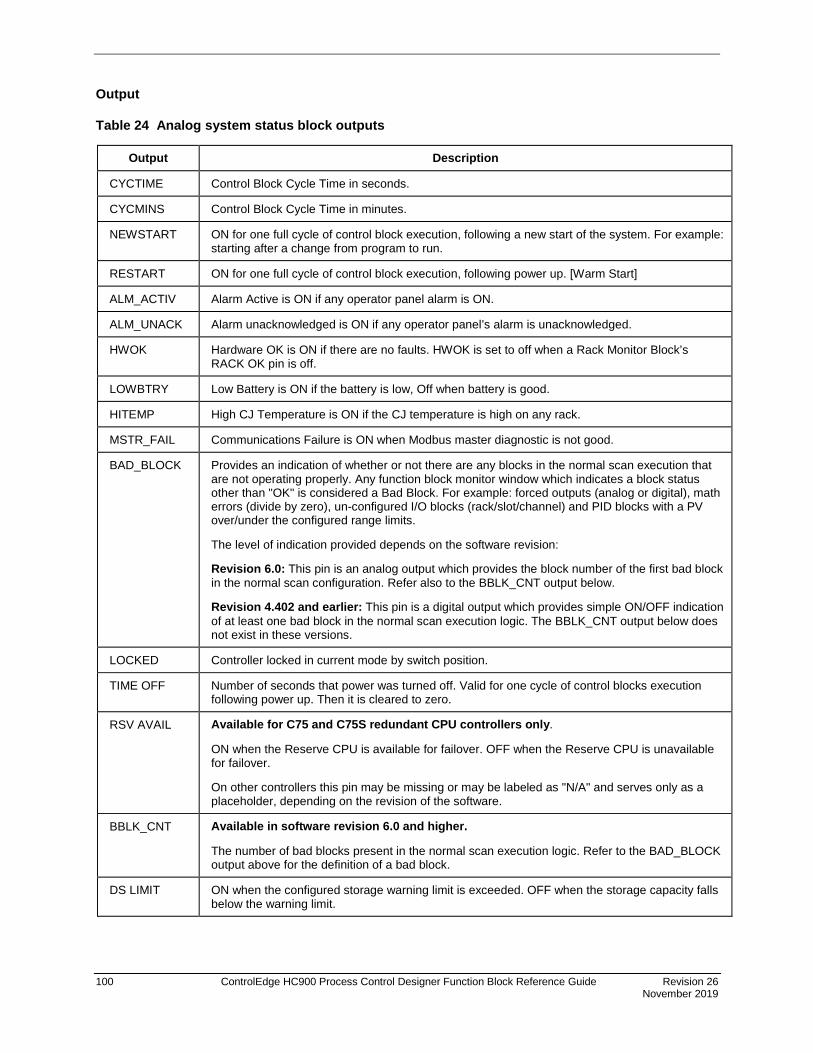
100 ControlEdge HC900 Process Control Designer Function Block Reference Guide Revision 26 November 2019
Output
Table 24 Analog system status block outputs
Output Description
CYCTIME Control Block Cycle Time in seconds. CYCMINS Control Block Cycle Time in minutes. NEWSTART ON for one full cycle of control block execution, following a new start of the system. For example:
starting after a change from program to run. RESTART ON for one full cycle of control block execution, following power up. [Warm Start] ALM_ACTIV Alarm Active is ON if any operator panel alarm is ON. ALM_UNACK Alarm unacknowledged is ON if any operator panel’s alarm is unacknowledged. HWOK Hardware OK is ON if there are no faults. HWOK is set to off when a Rack Monitor Block’s
RACK OK pin is off. LOWBTRY Low Battery is ON if the battery is low, Off when battery is good. HITEMP High CJ Temperature is ON if the CJ temperature is high on any rack. MSTR_FAIL Communications Failure is ON when Modbus master diagnostic is not good. BAD_BLOCK Provides an indication of whether or not there are any blocks in the normal scan execution that
are not operating properly. Any function block monitor window which indicates a block status other than "OK" is considered a Bad Block. For example: forced outputs (analog or digital), math errors (divide by zero), un-configured I/O blocks (rack/slot/channel) and PID blocks with a PV over/under the configured range limits.
The level of indication provided depends on the software revision:
Revision 6.0: This pin is an analog output which provides the block number of the first bad block in the normal scan configuration. Refer also to the BBLK_CNT output below.
Revision 4.402 and earlier: This pin is a digital output which provides simple ON/OFF indication of at least one bad block in the normal scan execution logic. The BBLK_CNT output below does not exist in these versions.
LOCKED Controller locked in current mode by switch position. TIME OFF Number of seconds that power was turned off. Valid for one cycle of control blocks execution
following power up. Then it is cleared to zero. RSV AVAIL Available for C75 and C75S redundant CPU controllers only.
ON when the Reserve CPU is available for failover. OFF when the Reserve CPU is unavailable for failover. On other controllers this pin may be missing or may be labeled as "N/A" and serves only as a placeholder, depending on the revision of the software.
BBLK_CNT Available in software revision 6.0 and higher.
The number of bad blocks present in the normal scan execution logic. Refer to the BAD_BLOCK output above for the definition of a bad block.
DS LIMIT ON when the configured storage warning limit is exceeded. OFF when the storage capacity falls below the warning limit.
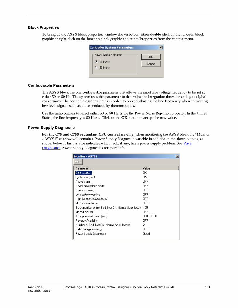
Revision 26 ControlEdge HC900 Process Control Designer Function Block Reference Guide 101 November 2019
Block Properties To bring up the ASYS block properties window shown below, either double-click on the function block graphic or right-click on the function block graphic and select Properties from the context menu.
Configurable Parameters The ASYS block has one configurable parameter that allows the input line voltage frequency to be set at either 50 or 60 Hz. The system uses this parameter to determine the integration times for analog to digital conversions. The correct integration time is needed to prevent aliasing the line frequency when converting low level signals such as those produced by thermocouples.
Use the radio buttons to select either 50 or 60 Hertz for the Power Noise Rejection property. In the United States, the line frequency is 60 Hertz. Click on the OK button to accept the new value.
Power Supply Diagnostic For the C75 and C75S redundant CPU controllers only, when monitoring the ASYS block the “Monitor - ASYS1” window will contain a Power Supply Diagnostic variable in addition to the above outputs, as shown below. This variable indicates which rack, if any, has a power supply problem. See Rack Diagnostics Power Supply Diagnostics for more info.

102 ControlEdge HC900 Process Control Designer Function Block Reference Guide Revision 26 November 2019
BCD Function Block
Description The BCD label stands for Binary Coded Decimal Translator.
This block is part of the Auxiliary category.
Function Accept up to 8 digital inputs in sequence and interprets the ON/OFF status of the first 4 inputs as a BCD value between 0 and 9 and the second 4 digits as a value between 10 and 80.
Input D1 = Bit 0 of the BCD lower digit
D2 = Bit 1 of the BCD lower digit
D4 = Bit 2 of the BCD lower digit
D8 = Bit 3 of the BCD lower digit
D10 = Bit 0 of the BCD upper digit
D20 = Bit 1 of the BCD upper digit
D40 = Bit 2 of the BCD upper digit
D80 = Bit 3 of the BCD upper digit
Output OUT = Analog output integer in the range of 0 to 99
OUT = (1* (1 if D1 is ON, else 0))+ (2* (1 if D2 is ON, else 0)) + (4* (1 if D4 is ON, else 0)) + (8* (1 if D8 is ON, else 0)) + (10* (1 if D10 is ON, else 0)) + (20* (1 if D20 is ON, else 0)) + (40* (1 if D40 is ON, else 0)) + (80* (1 if D80 is ON, else 0)))

Revision 26 ControlEdge HC900 Process Control Designer Function Block Reference Guide 103 November 2019
Block properties Double click on the function block to access the function block properties dialog box.
Example Figure 20 shows a Function Block Diagram configuration using a BCD function block to select a Recipe.
Figure 20 BCD function block example

104 ControlEdge HC900 Process Control Designer Function Block Reference Guide Revision 26 November 2019
BOOL Boolean Logic Function Block
Description The BOOL label stands for Free Form Logic.
This block is part of the Logic category.
Function Read digital inputs A through H and calculates the output based on specified Boolean logic function.
• Offers the following Boolean logic functions:
AND entered as * OR entered as + NOT entered as not XOR entered as ^ ( - Left parenthesis ) - Right Parenthesis
Inputs A = Block Input 1 B = Block Input 2 C = Block Input 3 D = Block Input 4 E = Block Input 5 F = Block Input 6 G = Block Input 7 H = Block Input 8
Output ERR = error during execution of the equation. Error = ON. No Error = OFF.
OUT = Calculated Output (ON or OFF)
A maximum of 50 tokens per equation is allowed. A token is an operator, a variable, or a pair of parentheses.

Revision 26 ControlEdge HC900 Process Control Designer Function Block Reference Guide 105 November 2019
TIP
• This function block consumes significantly more execution time than gate logic. Extensive use of this block in the fast logic scan can add significantly more time to the overall system cycle time.
• Use only the following list of words and characters in an equation:
− AND - logical AND,
− OR - logical OR,
− NOT - unary NOT,
− XOR - exclusive OR, or
− "( )", "[ ]", and " " parentheses - three types.
• A left parenthesis must have a matching right parenthesis.
• The matching parenthesis must be the same type, that is, "( )", "[ ]", or " ".
• Parentheses may be nested to any depth.
• Logicals AND, OR, and XOR must have a left and right operand.
• Unary NOT must have one operand to the right, and the operand must be enclosed in parentheses; for example, NOT(G).
Examples: (A*B)+C, (A+notB+C)*notD
Block properties
Double click on the function block to access the function block properties dialog box.

106 ControlEdge HC900 Process Control Designer Function Block Reference Guide Revision 26 November 2019
Configuration parameters
Table 25 BOOL function block configuration parameters
Properties Group Parameter Index # Parameter Description Value or Selection
Equations Equation Field
N/A Equation Field Enter the desired equation in this field
Functions Logic Functions
N/A NOT Double Click on a function to select from the list box
Operators Logic Operations
N/A * (AND) + (OR) ^ (XOR)
Double Click on an operation from the list box
Errors Error list N/A List of equation errors
Example
Figure 21 BOOL function block example

Revision 26 ControlEdge HC900 Process Control Designer Function Block Reference Guide 107 November 2019
CASTA Configuration Access Status
Description The CASTA label stands for Configuration Access Status Monitor. This block is part of the Alarm/Monitor Blocks category.
Function This function block provides read access to configuration access status values including the configuration file CRC (Cyclic Redundancy Check).
Versions The image shown above is for the first version of the block.
Restrictions There can be only one instance of the CASTA function block within a configuration.
Output
Serial No. Output Description Remarks
1 CFGCRC
This pin generates the CRC (Configuration Cyclic Redundancy Check) value of the downloaded configuration.
This value is zero for empty and invalid configuration
2 CFGCNT This pin generates the number of times the configuration is downloaded to controller.
The maximum value is 4294967295. The value neither increments nor rolls back to zero after the maximum limit is reached.
3 TCP-WR
This pin generates the number of times the unauthorized (Not in TCP-MODBUS access control list) TCP write is requested.
The maximum value is 4294967295. The value neither increments nor rolls back to zero after the maximum limit is reached.

108 ControlEdge HC900 Process Control Designer Function Block Reference Guide Revision 26 November 2019
Serial No. Output Description Remarks
4 PEER-WR
This pin generates the number of times the unauthorized (Not in PEER access control list) PEER write is requested.
The maximum value is 4294967295. The value neither increments nor rolls back to zero after the maximum limit is reached.
5 PWD-R This pin generates the number of times the controller password is changed.
The maximum value is 4294967295. The value neither increments nor rolls back to zero after the maximum limit is reached.
6 PWD-F This pin generates the number of times the controller password entries failed.
The maximum value is 4294967295. The value neither increments nor rolls back to zero after the maximum limit is reached.
7 PWD-S This pin generates the number of times the controller password entries succeeded.
8 PWD-D This pin represents the password status (ON: Password enabled; OFF: Password disabled)
Input
Input Description Remarks
RESET This will reset all parameters of the function block when changed from logic "OFF" to "ON"
Table 26 Pin details of CASTA function block
HOT Start
Cold Start
Power Cycle (With Battery)
Power Cycle (W/O Battery) Firmware download
CFGCNT HOLD HOLD HOLD RESET RESET
TCP-WR HOLD RESET RESET RESET RESET
PEER-WR HOLD RESET RESET RESET RESET

Revision 26 ControlEdge HC900 Process Control Designer Function Block Reference Guide 109 November 2019
HOT Start
Cold Start
Power Cycle (With Battery)
Power Cycle (W/O Battery) Firmware download
PWD-R HOLD HOLD HOLD RESET RESET
PWD-F HOLD HOLD HOLD RESET RESET
PWD-S HOLD HOLD HOLD RESET RESET
Monitor of CASTA function block
Block Properties

110 ControlEdge HC900 Process Control Designer Function Block Reference Guide Revision 26 November 2019
CALEVT Calendar Event Function Block
Description The CALEVT label stands for Calendar Event.
This block is part of the Counters/Timers category.
Function The Calendar Event Block compares user-entered time-and-date setpoints to the real-time clock to generate digital Event outputs. These Event outputs can be integrated into a control strategy to activate time-synchronized activities. For example, the Event outputs can be used turn-on or turn-off the lights in an office building. Each Calendar Event block supports up to eight Event outputs.
In addition, the block allows you to configure up to five sets of time-and-date setpoints, called Setpoint Groups. These Setpoint Groups can be used to activate different sets of time-and-date setpoints to handle different conditions. Using the example of an office building, Setpoint Groups can be used to activate a different set of time-and-date setpoints for each season of the year (Spring, Summer, Fall, and Winter). Each Calendar Event block supports five Setpoint Groups.
The block also allows you to configure up to 16 Special Days. On these Special Days the Calendar Event Block will override its normal Event processing for a 24-hour period. For example, you can configure selected Event outputs to remain off on designated holidays.
Input ENABLE = Enable; off = all event outputs (1-8) are off
^EVT1 = Event number 1 override input
^EVT2 = Event number 2 override input
^EVT3 = Event number 3 override input
^EVT4 = Event number 4 override input
^EVT5 = Event number 5 override input
^EVT6 = Event number 6 override input
^EVT7 = Event number 7 override input

Revision 26 ControlEdge HC900 Process Control Designer Function Block Reference Guide 111 November 2019
^EVT8 = Event number 8 override input ^EVT1 thru ^EVT8 allows the user to activate the output pins OUT1 thru OUT8 of the function block based on a condition other than time. The output action would be a one-shot.
SPGRP = Value of Event Set point that is to be loaded range 1 to 5 When SPGRP is connected to a variable, toggling the ^SET input is not required; the setpoint group is loaded automatically.
^SET = Loads the event set point group as indicated by the spgrp input signal.
SPGRP and ^SET input pins allow the user to activate one of five Setpoint Groups at any time. All the 8 events will be activated based on the settings in this Setpoint Group.
Output OUT1 = Calendar timer event 1 output
OUT2 = Calendar timer event 2 output
OUT3 = Calendar timer event 3 output
OUT4 = Calendar timer event 4 output
OUT5 = Calendar timer event 5 output
OUT6 = Calendar timer event 6 output
OUT7 = Calendar timer event 7 output
OUT8 = Calendar timer event 8 output Note: If the Event occurs when the Controller is OFF or not in RUN MODE, the event output will not turn ON until the event occurs again and the Controller is in RUN MODE
SPGRP = Value of Event Set point that was loaded range 1 to 5 at the SPGRP input pin.
BAD_CLK = Bad clock; on when error in system time.
Configuration Parameters The CALEVT properties dialog box is divided into 7 tab cards:
EVENT DETAILS SPECIAL DAYS EVENT SETPOINT 1 EVENT SETPOINT 2 EVENT SETPOINT 3 EVENT SETPOINT 4 EVENT SETPOINT 5
Click on the tab to access the properties for that tab.

112 ControlEdge HC900 Process Control Designer Function Block Reference Guide Revision 26 November 2019
EVENT DETAILS tab
Table 27 Calendar Event Details tab configuration parameters
Properties Group Parameter Index # Parameter Description Value or Selection
Block Order N/A
Execution Order Read Only. To change block order, right-click on a Function Block and select Execution Order.
Tag Name 16 character tag name (ASCII characters only)
Descriptor Block Descriptor
Event Names Event 1 thru Event 8
N/A Event Name 16 Characters Max (ASCII characters only).
Feedback Signals Feedback Signal Tags
N/A Feedback Signal tags for Event 1 thru Event 8
Press
Select a signal tag from the list in the “Signal Tag “dialog Box.

Revision 26 ControlEdge HC900 Process Control Designer Function Block Reference Guide 113 November 2019
SPECIAL DAYS tab The Calendar Event Block can be configured to override its normal Event processing when any of the 16 Special Days occurs. This override will remain in effect for the 24-hour period associated with the Special Day. This feature can be used to force selected Event outputs to remain off on designated holidays, for example.
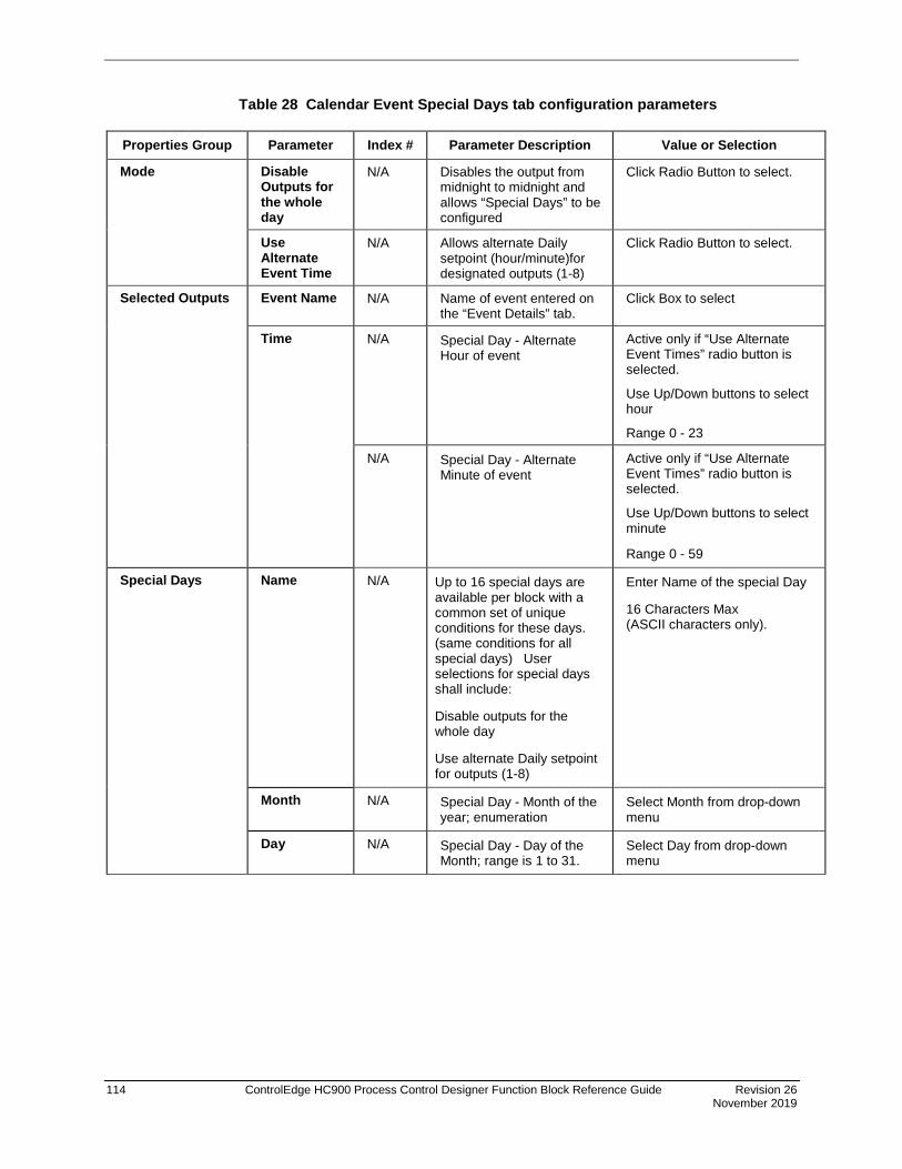
114 ControlEdge HC900 Process Control Designer Function Block Reference Guide Revision 26 November 2019
Table 28 Calendar Event Special Days tab configuration parameters
Properties Group Parameter Index # Parameter Description Value or Selection
Mode Disable Outputs for the whole day
N/A Disables the output from midnight to midnight and allows “Special Days” to be configured
Click Radio Button to select.
Use Alternate Event Time
N/A Allows alternate Daily setpoint (hour/minute)for designated outputs (1-8)
Click Radio Button to select.
Selected Outputs Event Name N/A Name of event entered on the “Event Details” tab.
Click Box to select
Time N/A Special Day - Alternate Hour of event
Active only if “Use Alternate Event Times” radio button is selected.
Use Up/Down buttons to select hour
Range 0 - 23
N/A Special Day - Alternate Minute of event
Active only if “Use Alternate Event Times” radio button is selected.
Use Up/Down buttons to select minute
Range 0 - 59
Special Days Name N/A Up to 16 special days are available per block with a common set of unique conditions for these days. (same conditions for all special days) User selections for special days shall include:
Disable outputs for the whole day
Use alternate Daily setpoint for outputs (1-8)
Enter Name of the special Day
16 Characters Max (ASCII characters only).
Month N/A Special Day - Month of the year; enumeration
Select Month from drop-down menu
Day N/A Special Day - Day of the Month; range is 1 to 31.
Select Day from drop-down menu

Revision 26 ControlEdge HC900 Process Control Designer Function Block Reference Guide 115 November 2019
EVENT SETPOINT 1 thru 5 tab

116 ControlEdge HC900 Process Control Designer Function Block Reference Guide Revision 26 November 2019
Table 29 Calendar Event Setpoint tab configuration parameters
Properties Group Parameter Index # Parameter Description Value or Selection
Setpoint Name N/A Event Setpoint Name 16 Characters (ASCII characters only)
Type Type of Event
N/A Type of event can be configured for different periods, where the event repeats at every occurrence
DISABLE – Selected Event is Disabled
5 day week – The configured event will occur at the same time Monday through Friday
7 day week – The configured event will occur at the same time Sunday through Saturday
Day of week – The configured event will occur once a week at the configured time
Monthly – The configured event will occur once every month at configured date and time
Yearly – The configured event will occur at the specific date and time
Month Month N/A User is only prompted for “Month” when the event_type is set to “Yearly”
Months of the year
Day Day N/A User is only prompted for “Day” when the event_type is set to “Yearly” or “Day_of_week” or “Monthly”
Day of the Month or Week
When Event Type = YEARLY, or MONTHLY, range is 1 to 31 (based on max # of days for calendar month) When Event Type = Monthly, 31 means last day of month even for months with less than 31 days When Event Type = Day_of_Week, range is Sunday to Saturday.
Hour Hour N/A Use up/down arrows to select hour of event
Hour of event; range 0 to 23
Minute Minute N/A Use up/down arrows to select minute of event
Minute of event; range 0 to 59

Revision 26 ControlEdge HC900 Process Control Designer Function Block Reference Guide 117 November 2019
Example The purpose of the example is to control the timing of lights in Building #1 for two different season sets. If you work after hours in this building, know that if the lights go out you can turn them back on. They will then stay on for a few hours and then turn off again.
Figure 22 CALEVT function block example
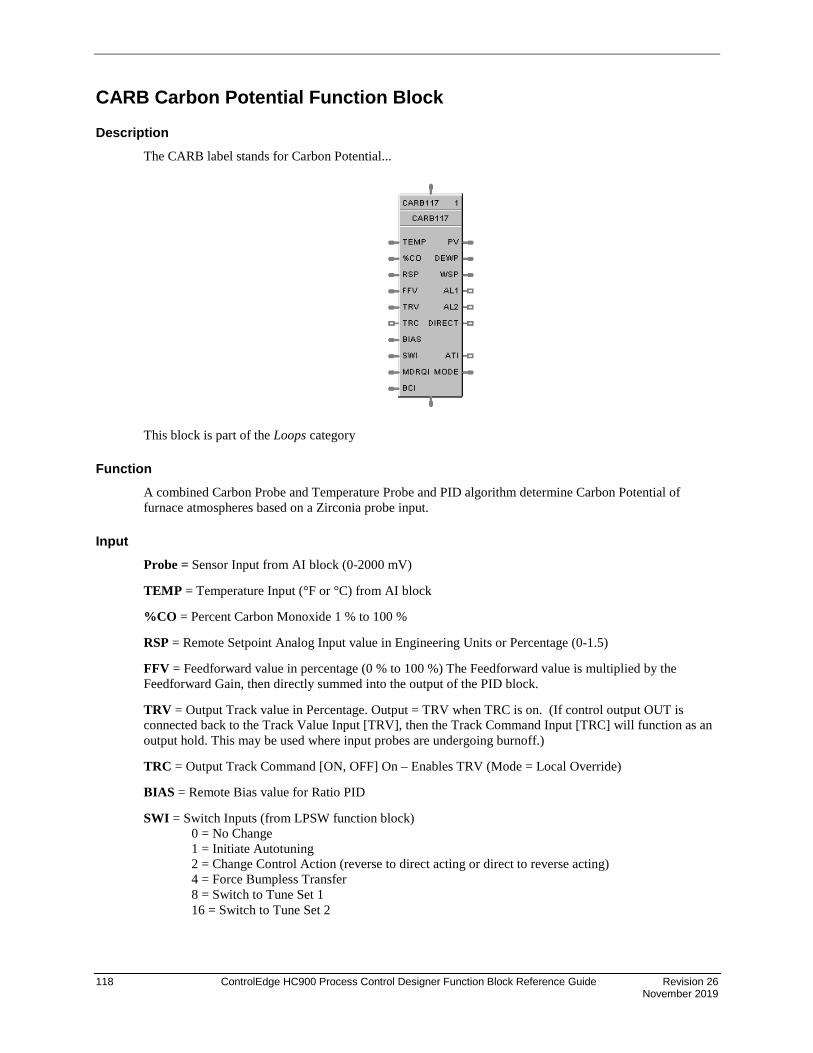
118 ControlEdge HC900 Process Control Designer Function Block Reference Guide Revision 26 November 2019
CARB Carbon Potential Function Block
Description The CARB label stands for Carbon Potential...
This block is part of the Loops category
Function A combined Carbon Probe and Temperature Probe and PID algorithm determine Carbon Potential of furnace atmospheres based on a Zirconia probe input.
Input Probe = Sensor Input from AI block (0-2000 mV)
TEMP = Temperature Input (°F or °C) from AI block
%CO = Percent Carbon Monoxide 1 % to 100 %
RSP = Remote Setpoint Analog Input value in Engineering Units or Percentage (0-1.5)
FFV = Feedforward value in percentage (0 % to 100 %) The Feedforward value is multiplied by the Feedforward Gain, then directly summed into the output of the PID block.
TRV = Output Track value in Percentage. Output = TRV when TRC is on. (If control output OUT is connected back to the Track Value Input [TRV], then the Track Command Input [TRC] will function as an output hold. This may be used where input probes are undergoing burnoff.)
TRC = Output Track Command [ON, OFF] On – Enables TRV (Mode = Local Override)
BIAS = Remote Bias value for Ratio PID
SWI = Switch Inputs (from LPSW function block) 0 = No Change 1 = Initiate Autotuning 2 = Change Control Action (reverse to direct acting or direct to reverse acting) 4 = Force Bumpless Transfer 8 = Switch to Tune Set 1 16 = Switch to Tune Set 2

Revision 26 ControlEdge HC900 Process Control Designer Function Block Reference Guide 119 November 2019
MDRQI = External Mode request (typically connected to the MDRQO output of a MDSW function block that encodes discrete switch inputs). 0 = No Change 1 = Manual Mode Request 2 = Auto Mode Request 4 = Local Setpoint Request 8 = Remote Setpoint Request
BCI = Back Calculation Input Value—See ATTENTION 1.
Output PV = Calculated Process Variable (% Carbon) for monitoring
DEWPT = Calculated Dewpoint
WSP = Working Setpoint in Engineering Units for monitoring (setpoint in use)
AL1 = Alarm 1 - Digital Signal
AL2 = Alarm 2 - Digital Signal
DIRECT = ON = Direct; OFF = Reverse
ATI = Autotune Indicator (ON = Autotune in Progress)
MODE = Loop mode status (typically connected to the Mode Flags block for encoding). Value indicates mode as follows: 0.0 RSP AUTO 1.0 RSP MAN 2.0 RSP Initialization Manual (See ATTENTION 1) 3.0 RSP Local Override (See ATTENTION 1) 4.0 LSP AUTO 5.0 LSP MAN 6.0 LSP Initialization Manual (See ATTENTION 1) 7.0 LSP Local Override (See ATTENTION 1)
BCO - Back Calculation Output (for blocks used as Cascade Secondary)—See ATTENTION 2.
ATTENTION
1. When a request to change from Auto to manual is received and:
− the request comes from the operator Interface, the request is ignored.
− the request comes from the Mode Switch (MDSW) function block, the request is retained and when leaving the Initialization Mode or Local Override Mode the loop will go to manual.
2. BCO output is provided for applications where the block is used as a cascade secondary. BCI input is provided for applications where the block is used as a cascade primary. When the BCO output of a secondary loop is connected to the BCI input of a primary loop, bumpless transfer is achieved when the secondary is switched into remote setpoint (i.e., cascade) mode. In addition, the primary loop is prevented from reset windup when the secondary is decoupled from the process. The secondary is decoupled from the process when it is in local setpoint mode or manual output mode, has reached a setpoint or output limit, or is integral limiting because its BCI input. For example, see Figure 76.
3. If Anti-Sooting is checked Working SetPoint (WSP) could be less than desired SetPoint (SP).

120 ControlEdge HC900 Process Control Designer Function Block Reference Guide Revision 26 November 2019
Configuration parameters The CARB properties dialog box is divided into 8 tab cards
GENERAL START/RESTART RSP RANGE/LIMIT TUNING ACCUTUNE III ALARMS CARBON POTENTIAL
Click on the tab to access the properties for that tab.
GENERAL tab

Revision 26 ControlEdge HC900 Process Control Designer Function Block Reference Guide 121 November 2019
Table 30 CARB General tab configuration parameters
Properties Group Parameter Index # Parameter Description Value or Selection
Block Order N/A Execution Order Read Only. To change block order, right-click on a Function Block and select Execution Order.
Tag Name 16 character tag name (ASCII characters only)
Descriptor Block Descriptor
Control Algorithm N/A Control Algorithm
Note: In PID B, step changes in setpoint will not bump the output; the output will slew smoothly to the new value.
In PID A, a step change in setpoint will result in a step change in output.
PID A - is normally used for 3 mode control. The output can be adjusted somewhere between 100 % and 0 %. It applies all three control actions -Proportional (P), Integral (I), and Derivative (D) - to the error signal.
PID B - Unlike the PID-A equation, the controller gives only an integral response to a setpoint change, with no effect on the output due to the Gain or Rate action, and gives full response to PV changes.
DUPA - like PIDA but provides an automatic method to switch tuning constant sets for Heat/Cool applications. DUPB - like PIDB but provides an automatic method to switch tuning constant sets for Heat/Cool applications.
NOTE: With PID B or DUPB selection, you will not be allowed to set RESET or RPM to 0.00 (OFF). Reset must be enabled.
Direction N/A Control Action DIRECT - PID action causes output to increase as process variable increases.
REVERSE - PID action causes output to decrease as process variable increases.
SP Tracking N/A Setpoint Tracking NONE
TRACK PV When control mode is “manual”, local setpoint tracks process variable.
TRACK RSP When setpoint is “remote setpoint”, local setpoint tracks remote setpoint.
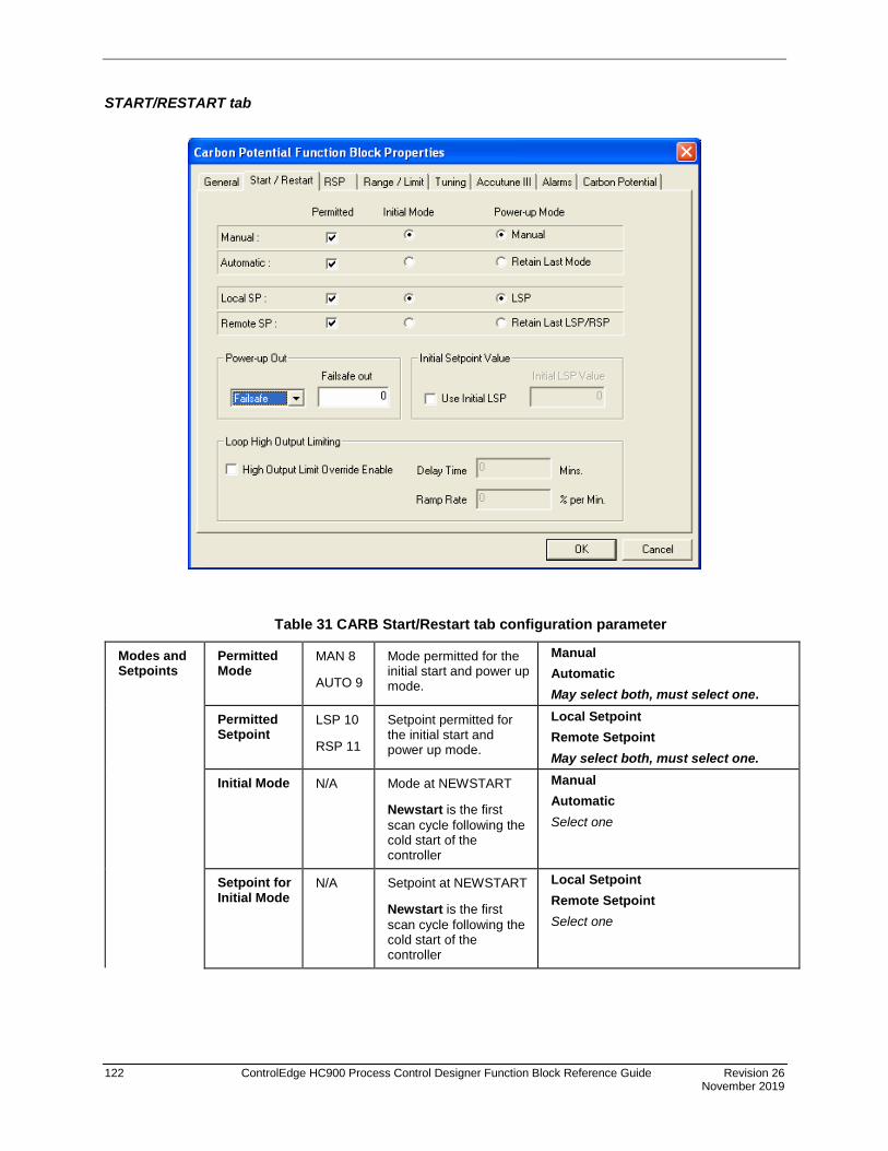
122 ControlEdge HC900 Process Control Designer Function Block Reference Guide Revision 26 November 2019
START/RESTART tab
Table 31 CARB Start/Restart tab configuration parameter
Modes and Setpoints
Permitted Mode
MAN 8
AUTO 9
Mode permitted for the initial start and power up mode.
Manual Automatic May select both, must select one.
Permitted Setpoint
LSP 10
RSP 11
Setpoint permitted for the initial start and power up mode.
Local Setpoint Remote Setpoint May select both, must select one.
Initial Mode N/A Mode at NEWSTART
Newstart is the first scan cycle following the cold start of the controller
Manual Automatic Select one
Setpoint for Initial Mode
N/A Setpoint at NEWSTART
Newstart is the first scan cycle following the cold start of the controller
Local Setpoint Remote Setpoint Select one
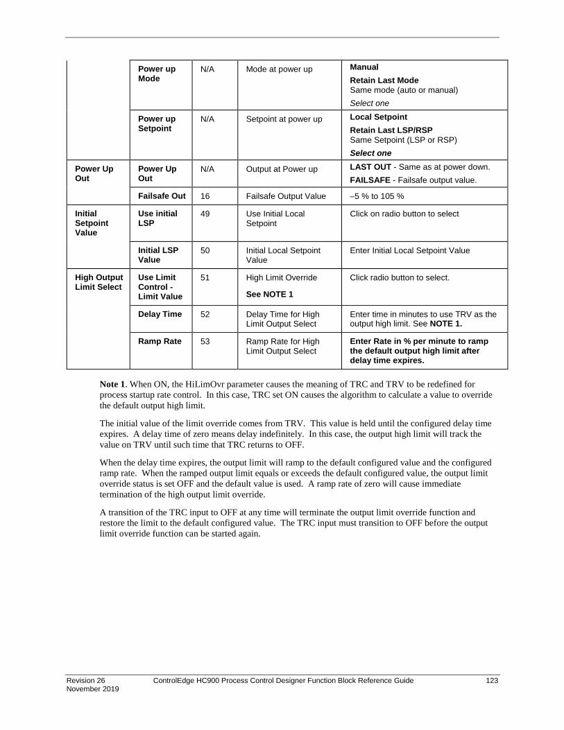
Revision 26 ControlEdge HC900 Process Control Designer Function Block Reference Guide 123 November 2019
Power up Mode
N/A Mode at power up Manual Retain Last Mode Same mode (auto or manual) Select one
Power up Setpoint
N/A Setpoint at power up Local Setpoint Retain Last LSP/RSP Same Setpoint (LSP or RSP) Select one
Power Up Out
Power Up Out
N/A Output at Power up LAST OUT - Same as at power down. FAILSAFE - Failsafe output value.
Failsafe Out 16 Failsafe Output Value –5 % to 105 %
Initial Setpoint Value
Use initial LSP
49 Use Initial Local Setpoint
Click on radio button to select
Initial LSP Value
50 Initial Local Setpoint Value
Enter Initial Local Setpoint Value
High Output Limit Select
Use Limit Control -Limit Value
51 High Limit Override
See NOTE 1
Click radio button to select.
Delay Time 52 Delay Time for High Limit Output Select
Enter time in minutes to use TRV as the output high limit. See NOTE 1.
Ramp Rate 53 Ramp Rate for High Limit Output Select
Enter Rate in % per minute to ramp the default output high limit after delay time expires.
Note 1. When ON, the HiLimOvr parameter causes the meaning of TRC and TRV to be redefined for process startup rate control. In this case, TRC set ON causes the algorithm to calculate a value to override the default output high limit.
The initial value of the limit override comes from TRV. This value is held until the configured delay time expires. A delay time of zero means delay indefinitely. In this case, the output high limit will track the value on TRV until such time that TRC returns to OFF.
When the delay time expires, the output limit will ramp to the default configured value and the configured ramp rate. When the ramped output limit equals or exceeds the default configured value, the output limit override status is set OFF and the default value is used. A ramp rate of zero will cause immediate termination of the high output limit override.
A transition of the TRC input to OFF at any time will terminate the output limit override function and restore the limit to the default configured value. The TRC input must transition to OFF before the output limit override function can be started again.

124 ControlEdge HC900 Process Control Designer Function Block Reference Guide Revision 26 November 2019
RSP tab
Table 32 CARB RSP tab configuration parameters
Properties Group Parameter Index # Parameter Description Value or Selection
Remote Setpoint Source and Units
Use RSP Input (EU)
N/A Use Remote Setpoint in Engineering Units
Click on radio button to select.
Use RSP Input (%)
N/A Use Remote Setpoint in Percent
Click on radio button to select.
Use LSP2 (EU)
N/A Use Local Setpoint #2 in Engineering Units
Click on radio button to select.
Ratio/Bias
(RSP Input Only)
No Ratio or Bias
N/A No ratio and bias applied to the function block
Click on radio button to select.
Use Local Bias
Use Bias value selected on Tab
Click on radio button to select Enter value at “Local Bias Value” on tab.
Use Bias Input
Use Bias value attached to an input to the block
Click on radio button to select.
Local Bias Value (EU)
46 Local bias value in engineering units
Enter local bias value.
Ratio 45 Gain value for Ratio PID –20 to +20

Revision 26 ControlEdge HC900 Process Control Designer Function Block Reference Guide 125 November 2019
RANGE/LIMIT tab

126 ControlEdge HC900 Process Control Designer Function Block Reference Guide Revision 26 November 2019
Table 33 CARB Range/limit tab configuration parameters
Properties Group Parameter Index # Parameter Description Value or Selection
Ranging PV High range
4 PV High Range Value –99999 to 99999
PV Low Range
5 PV Low Range Value –99999 to 99999
Display Decimal Places
N/A Number of digits to display after decimal point.
0 to 5
Units N/A Text to display for EU 6 characters
DEV Bar Range (EU)
N/A Deviation Bar Range on Operator Interface
–99999 to 99999
Limiting SP High Limit
17 Setpoint High Limit Value - prevents the local and remote setpoints from going above the value set here.
0 to 2.0 Used for anti-soot
SP Low limit
18 Setpoint Low Limit Value - prevents the local and remote setpoints from going below the value set here.
0 to 2.0
Out High Limit
20 Output High Limit Value - is the highest value of output beyond which you do not want the automatic output to exceed
–5 % to 105 %
Out Low Limit
21 Output Low Limit Value - is the lowest value of output beyond which you do not want the automatic output to exceed
–5 % to 105 %
SP Rate Down
41 Setpoint Rate Down value - when making a setpoint change, this is the rate at which setpoint will change from the original setpoint down to the new one.
0 (off) to 9999 (eu/min)
SP Rate Up 42 Setpoint Rate Up value - when making a setpoint change, this is the rate at which setpoint will change from the original setpoint up to the new one.
0 (off) to 9999 (eu/min)

Revision 26 ControlEdge HC900 Process Control Designer Function Block Reference Guide 127 November 2019
TUNING tab
Table 34 CARB Tuning tab configuration parameters
Properties Group Parameter Index # Parameter Description Value or Selection
Tuning Constants Prop Band or
Gain
0 PB1 or Gain 1
36 PB2 or gain 2
Proportional Band (PB) - is the percentage of the range of the measured variable for which a proportional controller will produce a 100 % change in its output.
Gain - is the ratio of output change (%) over the measured variable change (%) that caused it.
G =100 %PB %
where PB is the proportional Band (in %)
0.1 to 1000
0.1% to 1000 %

128 ControlEdge HC900 Process Control Designer Function Block Reference Guide Revision 26 November 2019
Properties Group Parameter Index # Parameter Description Value or Selection
Reset Minutes or Repeats/ Minute
2 Reset 1 38 Reset 2
RESET (Integral Time) - adjusts the controller’s output according to both the size of the deviation (SP-PV) and the time it lasts. The amount of corrective action depends on the value of Gain.
The reset adjustment is measured as how many times proportional action is repeated per minute (Repeats/minute) or how many minutes before one repeat of the proportional action occurs (Minutes/repeat).
0.02 to 50.00
Must be enabled for PID-B or DUP-B algorithm selections.
Rate Minutes
1 Rate 1
37 Rate 2
RATE action, in minutes affects the controller’s output whenever the deviation is changing; and affects it more when the deviation is changing faster.
0 or 0.1 to 10.00 minutes 0 = OFF
Feedforward Gain Feed-Forward Gain
43 Applies Gain to the Feedforward value (FFV). Feedforward Input is multiplied by this value.
0.0 to 10.0
Manual Reset Manual Reset
32 MANUAL RESET- is only applicable if you do not use RESET (Integral Time).
–100 to 100 (in % of Output)
ATTENTION
DUPA and DUPB algorithm types automatically select tuning set #2 for outputs between 50 % and –5 %. Tuning set #2 must be entered for DUPA and DUPB.

Revision 26 ControlEdge HC900 Process Control Designer Function Block Reference Guide 129 November 2019
ACCUTUNEIII tab
Table 35 CARB Accutune III tab configuration parameters
Properties Group Parameter Index # Parameter Description Value or Selection
Accutune III Type Disabled N/A Disables Accutune III Click on radio button to select.
Cycle Tuning Tuning parameter values are derived from the process response to the resultant action of causing the PV to oscillate about the SP value. See note 1.
Click on radio button to select.
SP Tuning Tuning based on the process response to a SP change. See note 2
Click on radio button to select.
SP Tuning Direction (For SP Tuning selection)
UP
Down
N/A The selection of either UP or DOWN results in the SP Change value added or subtracted from the present SP value.
Click on radio button to select.
SP Process
(For SP Tuning selection)
Process Gain
SPTune Change
16
57
Gain identification value for the process. This value is used to estimate the size of the initial output step for a SP Tune.
This defines the value of the initial output step change that is used as the target for process identification.
Range is 0.10 to 10.0 Normal value is 1.
Range is: 5 to 15 percent.
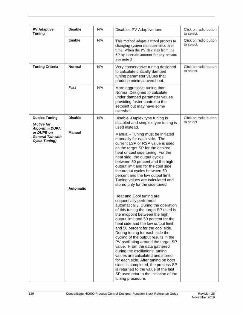
130 ControlEdge HC900 Process Control Designer Function Block Reference Guide Revision 26 November 2019
PV Adaptive Tuning
Disable N/A Disables PV Adaptive tune Click on radio button to select.
Enable N/A This method adapts a tuned process to changing system characteristics over time. When the PV deviates from the SP by a certain amount for any reason. See note 3
Click on radio button to select.
Tuning Criteria Normal N/A Very conservative tuning designed to calculate critically damped tuning parameter values that produce minimal overshoot.
Click on radio button to select.
Fast N/A More aggressive tuning than Norma. Designed to calculate under damped parameter values providing faster control to the setpoint but may have some overshot.
Duplex Tuning
(Active for Algorithm DUPA or DUPB on General Tab with Cycle Tuning)
Disable
Manual
Automatic
N/A Disable -Duplex type tuning is disabled and simplex type tuning is used instead.
Manual - Tuning must be initiated manually for each side. The current LSP or RSP value is used as the target SP for the desired heat or cool side tuning. For the heat side, the output cycles between 50 percent and the high output limit and for the cool side the output cycles between 50 percent and the low output limit. Tuning values are calculated and stored only for the side tuned.
Heat and Cool tuning are sequentially performed automatically. During the operation of this tuning the target SP used is the midpoint between the high output limit and 50 percent for the heat side and the low output limit and 50 percent for the cool side. During tuning for each side the cycling of the output results in the PV oscillating around the target SP value. From the data gathered during the oscillations, tuning values are calculated and stored for each side. After tuning on both sides is completed, the process SP is returned to the value of the last SP used prior to the initiation of the tuning procedure.
Click on radio button to select.

Revision 26 ControlEdge HC900 Process Control Designer Function Block Reference Guide 131 November 2019
Enable Fuzzy Overshoot
Suppression Click on block to select
34 Fuzzy Overshoot Suppression minimizes overshoot after a setpoint change or a process disturbance.
The fuzzy logic observes the speed and direction of the PV signal as it approaches the setpoint and temporarily modifies the internal controller response action as necessary to avoid an overshoot.
There is no change to the PID algorithm, and the fuzzy logic does not alter the PID tuning parameters.
This feature can be independently Enabled or Disabled as required by the application to work with “TUNE” On-Demand tuning.
ATTENTION
Accutune III is an On-demand tune only. You must provide a 0 to 1 transition to start another tuning cycle. The tuning will disturb the output to evaluate the tuning constants required.
TUNING NOTE: For this block, during tuning using either Cycle or SP tuning, a constant temperature value should be provided via the temperature input.
Note 1: CYCLE TUNING - This tuning method uses the measured ultimate gain and period to produce tuning parameter values. Cycle tuning does not distinguish between process lags and always results in gain based on PV amplitude and calculates values of Reset and Rate based on time of the SP crossings (The Reset value is always 4x the Rate value.) This method does not require a stable process initially and the process may be moving. Cycle tuning is applicable to Three Position Step control and can be used for integrating processes (level control).
Note 2: SP TUNING - When initiated the control loop is put into an initial temporary manual state until the process characteristics are identified. This period may last up to a minute. During this time the Tune status shows Not Ready, and then an initial output step is made using the preconfigured size and direction parameters along with the preset output value. The resultant process action is used to determine the tuning parameters and once the process identification has completed, the loop is returned to automatic control.
Note 3: PV ADAPTIVE TUNING - This method adapts a tuned process to changing system characteristics over time. When the PV deviates from the SP by a certain amount for any reason, the adaptive tuning algorithm becomes active and begins to observe the resulting PV action. If the process becomes unstable and oscillates, PV Adaptive Tuning eventually brings the process into control by retuning parameter values (as needed) using a systematic approach defined by an expert based method of tuning rules. Should the process not oscillate but be observed as too fast or sluggish, a different expert rules set is applied to result in the slowing down or speeding up of the process by adjusting certain tuning parameter values. This method continuously learns the process as PV deviations are observed and adapts the tuning parameters to the process response.

132 ControlEdge HC900 Process Control Designer Function Block Reference Guide Revision 26 November 2019
ALARMS tab
Table 36 CARB Alarms tab configuration parameters
Properties Group Parameter Index # Parameter Description Value or Selection
Alarm 1 Setpoint 1 23 Alarm 1 Setpoint 1 Value - this is the value at which you want the alarm type chosen below to activate
–99999 to 99999 in Engineering Units
Type N/A Alarm 1 Setpoint 1 Type - select what you want Alarm 1 Setpoint 1 to represent.
Selections: NO ALARM PV_HIGH PV_LOW DEV_HIGH DEV_LOW SP_HIGH SP_LOW OUT_HIGH OUT_LOW
Setpoint 2 24 Alarm 1 Setpoint 2 Value Same as Alarm 1 Setpoint 1
Type N/A Alarm 1 Setpoint 2 Type Same as Alarm 1 Setpoint 1
Alarm 2 Setpoint 1 25 Alarm 2 Setpoint 1 Value Same as Alarm 1 Setpoint 1
Type N/A Alarm 2 Setpoint 1 Type Same as Alarm 1 Setpoint 1
Setpoint 2 26 Alarm 2 Setpoint 2 Value Same as Alarm 1 Setpoint 1
Type N/A Alarm 2 Setpoint 2 Type Same as Alarm 1 Setpoint 1
Alarm Hysteresis Hysteresis 31 Alarm Hysteresis in % 0 % to 5 %

Revision 26 ControlEdge HC900 Process Control Designer Function Block Reference Guide 133 November 2019
CARBON POTENTIAL tab
Table 37 Carbon Potential tab configuration parameters
Properties Group Parameter Index #
Rev. 4.0 and higher/
Rev. 3.x and lower
Parameter Description Value or Selection
Furnace Properties
Furnace Factor
68/57 Allows you to adjust the % Carbon as measured by the controller to agree with the results of actual shim stock tests. This adjustment may be needed to correct for specific furnace characteristics such as atmosphere differences, probe location, and furnace leaks.
–0.5 %C to +0.5 %C
Use Anti soot constant
69/58 Activates anti-sooting feature that limits the working setpoint of the carbon control loop to a value that prevents sooting in the furnace.
Click on block to select
SP HLIM is used for anti-soot.
Low Temperature Limit
71/60 Holds controller output to 0 % until limit is exceeded.
0 to 2500 degrees F (1400° recommended) Unit should match C/F selection
Temperature Units
70/59 Probe temperature units for display.
Click on radio button to select
Fahrenheit or Centigrade
Percent Hydrogen
73/62 Percent Hydrogen 1 to 100 default = 40
CO Properties %CO 66/55 Allows you to adjust % Carbon 2.0 to 35.0

134 ControlEdge HC900 Process Control Designer Function Block Reference Guide Revision 26 November 2019
measurement to compensate for variations in the amount of CO in the carrier gas.
default = 20
Use Actual % CO
67/56 Function block will use the actual % Carbon Monoxide that is defined through an analog input.
Click on block to select
O2 Probe Manufacturer
Carbon Probe Vendor
N/A Select from Drop Down List of Manufacturers.
• Advanced Atmosphere Control Corp.
• Furnace Control Corp.
• Marathon Monitors
• Super Systems Inc.

Revision 26 ControlEdge HC900 Process Control Designer Function Block Reference Guide 135 November 2019
Example Figure 23 shows Function Block Diagrams using a CARB function block.
Figure 23 CARB function block examples
Carbon Potential Probe Burn-offApplication:
To clean a carbon probe periodicallyby blowing air across it for a specifictime.
In this configuration, a periodic timergenerates a pulse a designated timeinterval which suspends automaticcontrol and energizes a relay outputto cause air flow for a probe burn offcycle. Timers determine the probeburn-off period and allow time forthe probe recovery before returningthe loop to automatic control.
PTMR Output
MDSW Output
Burnoff Time
Time Delay to AUTO
ManualAuto Auto
Off delay #1
Off delay #2
Configuration Notes:Select probe Mfg.. type
O2 probe input: 0 to 2 V.(0 to 2000 range)
Select T/C type J or K etc..
Timing Diagram
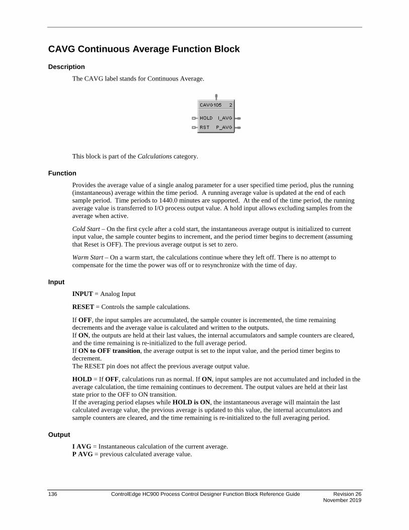
136 ControlEdge HC900 Process Control Designer Function Block Reference Guide Revision 26 November 2019
CAVG Continuous Average Function Block
Description The CAVG label stands for Continuous Average.
This block is part of the Calculations category.
Function Provides the average value of a single analog parameter for a user specified time period, plus the running (instantaneous) average within the time period. A running average value is updated at the end of each sample period. Time periods to 1440.0 minutes are supported. At the end of the time period, the running average value is transferred to I/O process output value. A hold input allows excluding samples from the average when active.
Cold Start – On the first cycle after a cold start, the instantaneous average output is initialized to current input value, the sample counter begins to increment, and the period timer begins to decrement (assuming that Reset is OFF). The previous average output is set to zero.
Warm Start – On a warm start, the calculations continue where they left off. There is no attempt to compensate for the time the power was off or to resynchronize with the time of day.
Input INPUT = Analog Input
RESET = Controls the sample calculations.
If OFF, the input samples are accumulated, the sample counter is incremented, the time remaining decrements and the average value is calculated and written to the outputs. If ON, the outputs are held at their last values, the internal accumulators and sample counters are cleared, and the time remaining is re-initialized to the full average period. If ON to OFF transition, the average output is set to the input value, and the period timer begins to decrement. The RESET pin does not affect the previous average output value.
HOLD = If OFF, calculations run as normal. If ON, input samples are not accumulated and included in the average calculation, the time remaining continues to decrement. The output values are held at their last state prior to the OFF to ON transition. If the averaging period elapses while HOLD is ON, the instantaneous average will maintain the last calculated average value, the previous average is updated to this value, the internal accumulators and sample counters are cleared, and the time remaining is re-initialized to the full averaging period.
Output I AVG = Instantaneous calculation of the current average. P AVG = previous calculated average value.

Revision 26 ControlEdge HC900 Process Control Designer Function Block Reference Guide 137 November 2019
Block properties
Double click on the function block to access the function block properties dialog box.
Configuration parameters
Table 38 Continuous average configuration parameters
Properties Group Parameter Index # Parameter Description Value or Selection
Set Avg. Period Averaging Period
0 Time period in which the Continuous Average will be calculated. When the averaging period elapses, the last valid value will be set equal to the instantaneous value. The internal accumulators and sample counters will be cleared and the time remaining will be re-initialize to the full average period.
0.1 to 1440.0 in minutes
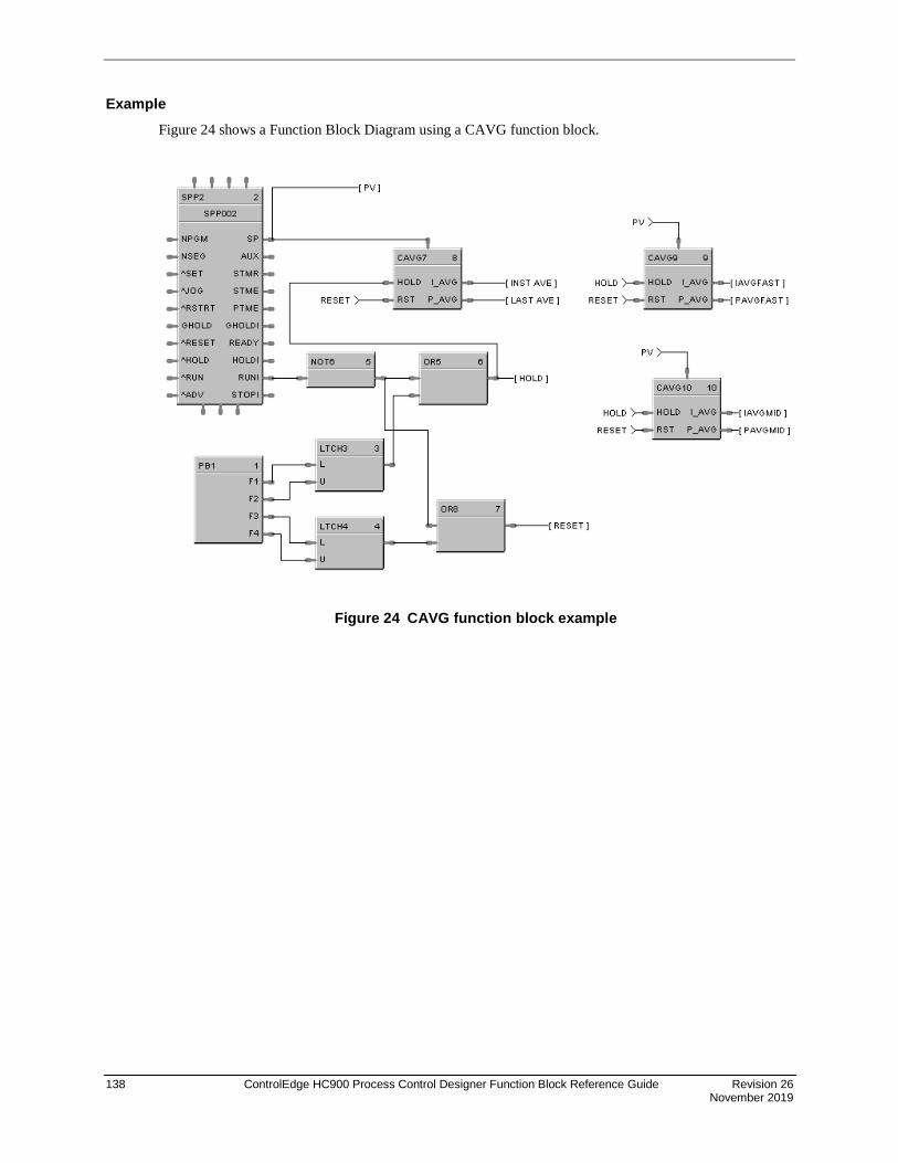
138 ControlEdge HC900 Process Control Designer Function Block Reference Guide Revision 26 November 2019
Example Figure 24 shows a Function Block Diagram using a CAVG function block.
Figure 24 CAVG function block example
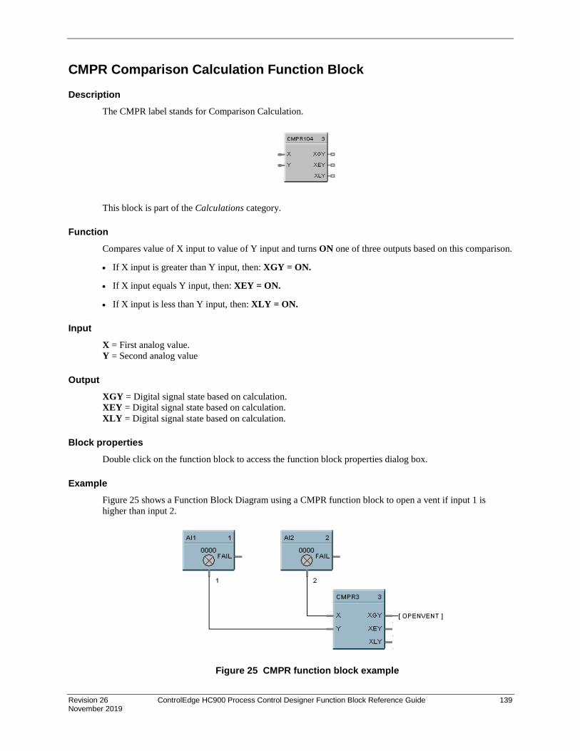
Revision 26 ControlEdge HC900 Process Control Designer Function Block Reference Guide 139 November 2019
CMPR Comparison Calculation Function Block
Description The CMPR label stands for Comparison Calculation.
This block is part of the Calculations category.
Function Compares value of X input to value of Y input and turns ON one of three outputs based on this comparison.
• If X input is greater than Y input, then: XGY = ON.
• If X input equals Y input, then: XEY = ON.
• If X input is less than Y input, then: XLY = ON.
Input X = First analog value. Y = Second analog value
Output XGY = Digital signal state based on calculation. XEY = Digital signal state based on calculation. XLY = Digital signal state based on calculation.
Block properties Double click on the function block to access the function block properties dialog box.
Example Figure 25 shows a Function Block Diagram using a CMPR function block to open a vent if input 1 is higher than input 2.
Figure 25 CMPR function block example

140 ControlEdge HC900 Process Control Designer Function Block Reference Guide Revision 26 November 2019
DC Device Control Function Block
Description The DC label stands for Device Control.
This block is part of the Auxiliary category.
Function The Device Control function block is normally used to control pumps. Based on certain events listed in Table 39 the device will be placed into one of six states: READY, PRESTART, STARTING, RUNNING, STOPPING, DISABLED, or FAILED. The READY (off state) is the initial state of the function block. Each configuration is limited to a maximum of 16 Device Control function blocks. Forcing of outputs is NOT permitted within this block.
Inputs REQ = (run request) when ON [Logic 1], puts the device in the Starting / Running state. When OFF, puts the device in Stopping / Ready state.
FDBK = feedback from the controlled device; ON = device has started, OFF = device has not started.
ERR = (in) – ON when the controlled device reports a failure, causes the device control to transition to the FAILED state. OFF = No device failure.
^RST = an OFF to ON transition will manually reset the control when it is in the FAILED state and return to the READY state.
DIS = (disable) When OFF, the device control operates normally. When ON, immediately transitions to the DISABLED state, it prevents the device from starting if in the ready state or immediately shuts-down the device if it is currently starting up or running state.

Revision 26 ControlEdge HC900 Process Control Designer Function Block Reference Guide 141 November 2019
Outputs OUT = Primary block output – the output is ON in the RUNNING and STOPPING states, else OFF.
RDY = (ready) ON when the control is in the Ready State (the controlled device is off and waiting for a request to run), otherwise OFF.
PRES = (prestart) ON while in the prestart state (a request to run the device has been received and the start delay timer is >0, otherwise OFF.
STRT = (starting) ON while in the start state (start timer has expired and there is a request to start the device. The device feedback timer is started. The device is being monitored for failures),
RUN= (running) ON while in the Running state (the controlled device has completed start up (Device Feedback) and is now running; occurs after the start delay timer expires; device is being monitored for failures and feedback that it started) otherwise OFF.
STOP = (stopping) ON while in the Stopping state (the controlled device is requested to turn off; stop delay timer is running; device is being monitored for failures, interlocking and returning to the run state), otherwise OFF.
FAIL = (failed) ON when the control is in the Failed state (the controlled device reported a failure or did not start up in time; device is being monitored for a manual or automatic reset), otherwise OFF.
DIS = (disabled) ON while in the Disabled state (the controlled device is locked-out; it cannot start running until the disable input signal turns OFF), otherwise OFF.
STI = An enumeration representing the different states of the control. Where: 0 = NOT USED, 1 = READY, 2 = PRESTART, 3 = STARTING, 4 = RUNNING, 5 = STOPPING, 6 = DISABLE, 7 = FAIL.
Conditions for transition from FAIL to READY state One of the following conditions must occur to transition from the FAIL state to the READY state:
a) If a Feedback error is the initial reason for the failure, then a manual reset is the only method for returning to the Ready state.
b) If Automatic-Reset is selected, then you return to the Ready state when Device Failure input turns OFF.
c) If Automatic-Reset is not selected, then you return to the Ready state when Device Failure input is OFF and the Reset input transitions OFF to ON.

142 ControlEdge HC900 Process Control Designer Function Block Reference Guide Revision 26 November 2019
Monitored events and device states Table 39 shows which events are monitored in each state.
Table 39 Monitored events and device states
MONITORED EVENTS
DEVICE STATES
READY (Note 1)
PRE-START
STARTING RUNNING
DISABLED (Notes 1,2)
STOPPING FAILED
Run Request turns ON X X
Run Request turns OFF X X X
Disable (ON) X X X X X
Disable (OFF) X
Feedback from Device X X
Device (ERR) Fail ON X X X X
Device (ERR) Fail OFF X Note 3
Reset (Rising Edge) X
Start Delay Timer Expires (edge)
X
Feedback Timer Expires (edge)
X X
Stop Delay Timer Expires (edge)
X
Notes:
1. If a device fails while in the state of READY or DISABLE, the device failure is not recognized until the control goes into the PRESTART state.
2. There are restrictions when the control goes into the Disable state from the Running State. The device is immediately turned OFF without a Stop Delay. When the disable turns OFF, the control changes to the Ready state.
3. ERR Off (device fail) is monitored in Failed state, only if:
a) Failed input caused the failure, and
b) Auto Reset is enabled.
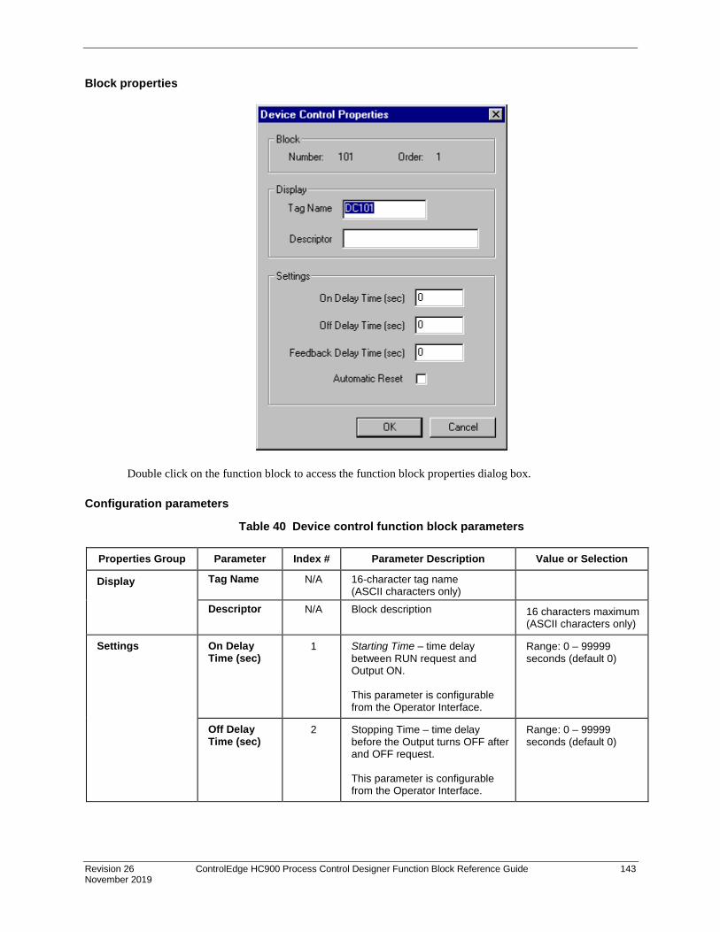
Revision 26 ControlEdge HC900 Process Control Designer Function Block Reference Guide 143 November 2019
Block properties
Double click on the function block to access the function block properties dialog box.
Configuration parameters
Table 40 Device control function block parameters
Properties Group Parameter Index # Parameter Description Value or Selection
Display Tag Name N/A 16-character tag name (ASCII characters only)
Descriptor N/A Block description 16 characters maximum (ASCII characters only)
Settings On Delay Time (sec)
1 Starting Time – time delay between RUN request and Output ON. This parameter is configurable from the Operator Interface.
Range: 0 – 99999 seconds (default 0)
Off Delay Time (sec)
2 Stopping Time – time delay before the Output turns OFF after and OFF request. This parameter is configurable from the Operator Interface.
Range: 0 – 99999 seconds (default 0)

144 ControlEdge HC900 Process Control Designer Function Block Reference Guide Revision 26 November 2019
Properties Group Parameter Index # Parameter Description Value or Selection
Feedback Delay Time (sec)
3 Feedback-Fail-Delay: if during this time-period there is no feedback from a device confirming the control is in the Running state, then the block enters the FAIL state and Out is turned OFF.
If a device sends feedback during this time-period, then this timer is reset.
This parameter is configurable from the Operator Interface.
Range: 0 – 99999 seconds (default 0)
Automatic Reset
(Click on Box to turn ON)
0 if set to AUTO, then the block will reset itself after the failure (Fail input) turns off. If set to MANUAL, a Reset (signal input or from the Operator Interface station) is required to remove the failure condition. This parameter is determined when the block is configured.
ON = Automatic Reset (box selected)
OFF = Manual Reset (box deselected)
Example Figure 26 shows a Function Block Diagram using a Device Control function block to control a pump to fill a tank.
Figure 26 DC function block example

Revision 26 ControlEdge HC900 Process Control Designer Function Block Reference Guide 145 November 2019
DCMP Deviation Compare Function Block
Description The DCMP label stands for Deviation Compare.
This block is part of the Calculations category
Function Compares up to 6 analog inputs to a + or – user-entered deviation setpoint to a 7th input reference value and sets the output true if any input exceeds the deviation value from the reference value. Output is off if all inputs are less than the deviation.
Plus Dev Compare Value = Reference input + User entered Plus Deviation value
Minus Dev Compare Value = Reference input - User entered Minus Deviation value (Minus Deviation value should be a positive number)
If any IN (1-6)> the Plus Dev Compare value, Out = ON
If any IN (1-6) < the Minus Dev Compare value, Out = ON
ATTENTION
When the reference input is the average of the 6 inputs, the block performs deviation from average.
Input IN1 = Input 1 IN2 = Input 2 IN3 = Input 3 IN4 = Input 4 IN5 = Input 5 IN6 = Input 6 Y =Reference Input
ATTENTION
All inputs should be used or a single value should be connected to multiple inputs. Unused inputs will default to 0.
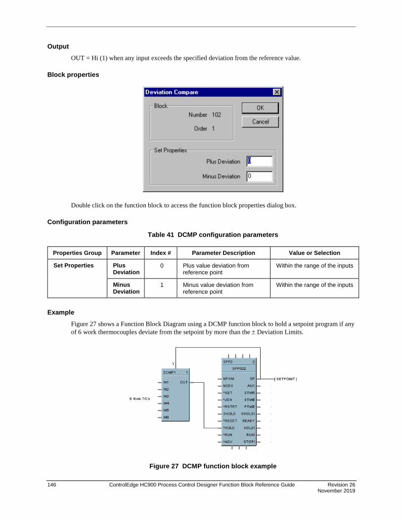
146 ControlEdge HC900 Process Control Designer Function Block Reference Guide Revision 26 November 2019
Output OUT = Hi (1) when any input exceeds the specified deviation from the reference value.
Block properties
Double click on the function block to access the function block properties dialog box.
Configuration parameters
Table 41 DCMP configuration parameters
Properties Group Parameter Index # Parameter Description Value or Selection
Set Properties Plus Deviation
0 Plus value deviation from reference point
Within the range of the inputs
Minus Deviation
1 Minus value deviation from reference point
Within the range of the inputs
Example Figure 27 shows a Function Block Diagram using a DCMP function block to hold a setpoint program if any of 6 work thermocouples deviate from the setpoint by more than the ± Deviation Limits.
Figure 27 DCMP function block example

Revision 26 ControlEdge HC900 Process Control Designer Function Block Reference Guide 147 November 2019
DDEC Digital Decoder Function Block
Description The DDEC label stands for Digital Decoder.
This block is part of the Auxiliary category.
Function The Digital Decoder function converts an analog value from the Value Input to the binary equivalent value on the 16 digital outputs 1 through 16. The Value Input accepts whole numbers between 0 and 65535. Fractional values are ignored. The output value OCNT (bottom of block) indicates the total number of digital outputs that are ON as an analog value.
For example, a value of 285 would be represented by binary 0000000100011101, where OUT 1 is LSB and OUT 16 is MSB. OCNT = 5 (OUT 1, 3, 4, 5, 9 are ON).
All 16 outputs and the OCNT signal pin are monitored.
Forcing of the outputs is not permitted.
Inputs VALUE = Whole number analog input value between 0 and 65535.
Outputs Sixteen digital outputs, OUT 1 through OUT 16, with OUT 1 = LSB and OUT 16 = MSB.
OCNT = Analog value representing the number of digital outputs (OUT 1 through OUT 16) that are set to ON.

148 ControlEdge HC900 Process Control Designer Function Block Reference Guide Revision 26 November 2019
Example Figure 29 shows a Function Block Diagram using a DDEC function block.
Figure 28 DDEC function block example

Revision 26 ControlEdge HC900 Process Control Designer Function Block Reference Guide 149 November 2019
DENC Digital Encoder Function Block
Description The DENC label stands for Digital Encoder.
This block is part of the Auxiliary category.
Function This block’s main function is to totalize the number of ON states from up to 16 digital signals. The block digitally encodes up to 16 digital inputs to a single floating point output value.
Forcing of the output is not permitted.
Inputs Sixteen digital inputs: Example: ON causes the input to be included in the total output. Unconnected pins default to OFF.
IN 1 = Digital Input 1 IN 9 = Digital Input 9 IN 2 = Digital Input 2 IN 10 = Digital Input 10 IN 3 = Digital Input 3 IN 11 = Digital Input 11 IN 4 = Digital Input 4 IN 12 = Digital Input 12 IN 5 = Digital Input 5 IN 13 = Digital Input 13 IN 6 = Digital Input 6 IN 14 = Digital Input 14 IN 7 = Digital Input 7 IN 15 = Digital Input 15 IN 8 = Digital Input 8 IN 16 = Digital Input 16
Outputs ICNT = Sum of the Inputs set to ON.
DENC = Bit encoded value representing the state of the Input pins (IN1 - IN16); where IN1 is the LSB and IN16 is the MSB.
NOTE: This pin is typically connected to an Alternator block's "DRDYS" input pin.

150 ControlEdge HC900 Process Control Designer Function Block Reference Guide Revision 26 November 2019
Block properties Double click on the function block to access the function block properties dialog box.
Example Figure 29 shows a Function Block Diagram using a DENC function block using multiple digital status to select an appropriate setpoint for a flow loop.
Figure 29 DENC function block example

Revision 26 ControlEdge HC900 Process Control Designer Function Block Reference Guide 151 November 2019
DEWP Function Block
Description The DEWP label stands for Dewpoint Calculation.
This block is part of the Calculations category.
Function Monitors Dewpoint or Carbon Potential, or uses a Zirconia Probe sensor input to supply a Dewpoint PV to a PID function block for Dewpoint control. Use in conjunction with other blocks including a PID to generate more elaborate control strategies than that provided by the Carbon potential (CARB) function block.
Inputs Probe = Oxygen Sensor Input from AI (0-2 mV) TEMP = Temperature Input (°F or °C) from AI Input %CO = Percent Carbon Monoxide Input 1 - 100 %
Outputs DEWPT = Calculated Dewpoint Output %C = Calculated Percent Carbon Output SPHLIM = Control Setpoint High Limit for Anti-soot. WRLIM = Command to write the setpoint high limit. LOTEMP = ON when TEMP is <= calculated low temperature dropoff.

152 ControlEdge HC900 Process Control Designer Function Block Reference Guide Revision 26 November 2019
Block properties
Double click on the function block to access the function block properties dialog box.
Configuration parameters
Table 42 Dewpoint function block parameters
Properties Group Parameter Index # Parameter Description Value or Selection
Furnace Properties
Furnace Factor
2 Allows you to adjust the % Carbon as measured by the controller to agree with the results of actual shim stock tests. This adjustment may be needed to correct for specific furnace characteristics such as atmosphere differences, probe location, and furnace leaks.
–0.5 %C to +0.5 %C
Use Anti-Soot Constant
3 Activates anti-sooting feature that limits the working setpoint of the carbon control loop to a value that prevents sooting in the furnace.
Click on block to select
SP HLIM is used for anti-soot.
Low Temperature Limit
5 Holds controller output to 0 % until limit is exceeded.
0 to 2500 degrees F (1400° recommended) Unit should match C/F selection.
Temperature Units
4 Probe temperature units for display.
Click on radio button to select. Fahrenheit or Celsius
Percent Hydrogen
7 Percent Hydrogen 1 to 100
default = 40

Revision 26 ControlEdge HC900 Process Control Designer Function Block Reference Guide 153 November 2019
CO Properties %CO 0 Allows you to adjust % Carbon measurement to compensate for variations in the amount of CO in the carrier gas.
2.0 to 35.0
default = 20
Use Actual % CO
1 Function block will use the actual % Carbon Monoxide that is defined through an analog input.
Click on block to select.
O2 Probe Manufacturer
Carbon Probe Manufacturer
N/A Select from Drop Down List of Manufacturers.
• Advanced Atmosphere Control Corp.
• Furnace Control Corp. • Marathon Monitors • Super Systems Inc.
Example Figure 30 shows a Function Block Diagram using a DEWP function block. This application uses the Dew Point function block to calculate dew point based on using a carbon probe. A typical example might be for control of an endothermic atmosphere generator. Alternatively, a Honeywell dew point transmitter could be used for a more direct measurement.
Figure 30 DEWP function block example

154 ControlEdge HC900 Process Control Designer Function Block Reference Guide Revision 26 November 2019
DI Function Block
Description The DI label stands for Discrete Input.
This block is part of the I/O Blocks categories.
Function Discrete input blocks are used to process the digital status of a specific channel of a discrete input module. Each block requires a module and channel number during configuration. The Input status may be inverted.
If Digital Point is ON, then OUT = ON.
Output OUT = Digital Signal
Block properties
Double click on the function block to access the function block properties dialog box.

Revision 26 ControlEdge HC900 Process Control Designer Function Block Reference Guide 155 November 2019
Configuration parameters
Table 43 Digital input configuration parameters
Properties Group Parameter Index # Parameter Description Value or Selection
Address Rack 0 Rack on selected I/O Module From 1 to 5
I/O Module Address of select I/O Module From 1 to 12
Channel Channel on selected I/O Module From 1 to 16 or 32.
1 If INVERT is selected, OUT = inverse of physical input. The slash will be present in the CONTACT symbol only when the invert box is selected on the dialog box. (See below.)
Failsafe Failsafe ON N/A set the output of the block to OFF when failure is detected
Click on radio button to select
Failsafe OFF N/A set the output of the block to ON when failure is detected
Click on radio button to select
Failsafe HOLD
N/A hold the output at the last value just prior to the failure being detected
Click on radio button to select

156 ControlEdge HC900 Process Control Designer Function Block Reference Guide Revision 26 November 2019
Example Figure 31 shows a Function Block Diagram using DI function blocks in a basic Series Parallel Circuit.
Figure 31 Digital input function block example

Revision 26 ControlEdge HC900 Process Control Designer Function Block Reference Guide 157 November 2019
DIGIMP Safety Digital Import Function Block Description
The DIGIMP label is short-hand for the Safety Digital Import block.
This block belongs to the Communications category and is only available on SIL certified devices, such as the C30S, C50S, C70S, and C75S using version 6.3x or above.
Function
The Safety Digital Import block is a communication block that allows a configuration to import selected digital signals from other external configurations. These signals are exported within an XML file generated by selecting the “Safety Peer Export Enable” option within the Signal Dialog, and then saving the configuration. The XML is saved with the configuration filename, with the ‘.xml’ file extension. With this block, a user is able to share signals between multiple configurations. The Safety Digital Import block has one output for FAIL. The Safety Digital Import block allows the user to set a Failsafe Option for “Off” or “On” or to “Hold” current value.
Similar to how a ‘Connector’ functions, the user cannot import a ‘Process’ signal (non-highlighted signal) into ‘Safety’ worksheet. The user is able to import a ‘Safety’ signal (yellow highlighted) into a ‘Process’ sheet however.
Inputs
DIS – DIS is the Disable pin that disables the digital signal import updates between the two controllers. Attaching a ‘high’ signal to disable sends all signals imported from that controller into failsafe. Attaching the NO_SCAN pin of the corresponding SAFPDE block will associates the failsafe timeout action configured in the SAFPDE block to the DIGIMP block.
Outputs
FAIL – Failsafe pin to signal that the data has reached its stale limit
Block Properties
After adding a Safety Digital Import block, opening the properties will prompt the user to select a ‘.xml’ file from a previously saved configuration with which to import a digital signal from.

158 ControlEdge HC900 Process Control Designer Function Block Reference Guide Revision 26 November 2019
The above image shows several XML files that are automatically generated after saving a configuration.
After selecting the ‘.xml’ file, the following screen is shown to allow the user to select the digital signal to import:

Revision 26 ControlEdge HC900 Process Control Designer Function Block Reference Guide 159 November 2019
The Safety Digital Import have a ‘Signal Tag’, ‘Description’, ‘Type’, external signal ‘Number’, ‘On Label’ and an ‘Off Label’.
Once a signal is selected, and ‘OK’ is pressed, the block will hold the information from the previous dialog, as shown below:

160 ControlEdge HC900 Process Control Designer Function Block Reference Guide Revision 26 November 2019
The Digital Import block now configured.
Configuration Parameters
In the properties page, the user is able to configure the failsafe options for the block only. The user can choose Failsafe to be ‘Off’, ‘On’, or ‘Hold’, which continues to output the last known good value.
Parameter Index # Parameter Description Value Or Selection Default
Failsafe N/A Action to be taken when the block goes to fail.
Hold – output will hold to last good state
OFF – output will go to OFF state
ON – output will go to ON state
Click on radio button to select
OFF
Related Function Blocks
SAFPDE – Safety Peer Monitor block

Revision 26 ControlEdge HC900 Process Control Designer Function Block Reference Guide 161 November 2019
Digital Input Voting
Description The DI-V label stands for Digital Input Voting.
This block is part of the I/O Blocks category.
Function Provides the digital status of a digital input point and provides interface to other algorithms and functions.
The output status may be inverted.
If Digital Point is ON, then OUT = ON
DI-V differs from the DI block in that multiple inputs (up to 3) may be specified, and the values of the inputs (whose channel has not failed) must match for the input value to be considered good overall. Otherwise the FAIL pin becomes ON and the Fail-safe value is used as output instead of any input value. If there is only one input used, then the state of the single channel determines the state of the FAIL pin.
If none of the inputs are used (i.e. all three are not enabled by user), the function block will use the Fail-safe value as output.
Please refer to the descriptions of the FAIL, SFAIL, and VFAIL pins below to get a good understanding of the block behavior.
Input Digital value(s) from specified real I/O address(s).
Output OUT = Digital signal.
FAIL = Failed – If ON, indicates that the block output is set to Fail-safe. Possible cause for this is:
In cases where three inputs are used:
One input has a failed channel and the good channels have a validation failure.
OR
All three inputs have failed channels.
In cases where two inputs are used:
Two inputs have good channels and a validation failure.

162 ControlEdge HC900 Process Control Designer Function Block Reference Guide Revision 26 November 2019
OR
Both inputs have failed channels.
SFAIL = Source Failure – If ON, indicates a failure of one or more of the digital channel(s). Possible cause for this is:
Power failure
One of the DI channels failed
VFAIL = Validation Failure – If ON, indicates that the values of the “good” channels disagree.
Block properties
Double click on the function block to access the function block properties dialog box.

Revision 26 ControlEdge HC900 Process Control Designer Function Block Reference Guide 163 November 2019
Configuration parameters Properties
Group Parameter Index # Parameter Description Value or Selection
Block Order N/A Execution Order for Block
To change, See "Execution Order".
Read Only.
Digital Input Address
Use Input A 4 Enable or Disable Input A Click on checkbox to select or deselect
Use Input B 5 Enable or Disable Input B Click on checkbox to select or deselect
Use Input C 6 Enable or Disable Input C Click on checkbox to select or deselect
Rack
(for each Input)
N/A This is the address of the selected Rack.
Enter a value: from 1 to 5.
I/O Module (for each Input)
N/A Address of selected I/O module Enter a value: from 1 to 12
Channel (for each Input)
N/A Channel on selected I/O Module Enter a value:1 to 16, depending on module type.
Invert N/A If INVERT is selected, OUT = inverse of physical input.
The slash will be present in the CONTACT symbol only when the invert box is selected on the dialog box.
Click on checkbox to select or deselect
Failsafe
Failsafe - Off N/A Sets the output of the block to OFF when failure is detected. This is the only failsafe option available if the block is on a safety worksheet.
Click on Radio button to select.
Failsafe - On N/A Sets the output of the block to ON when failure is detected.
Click on Radio button to select.
Failsafe - Hold N/A Holds the output at the last value just prior to the failure being detected.
Click on Radio button to select.

164 ControlEdge HC900 Process Control Designer Function Block Reference Guide Revision 26 November 2019
Example Figure 01 below shows a function block diagram using a DI-V function block. The AI block reads in analog input values from real I/O addresses, and then passes the calculated value to the PID block, for it to control the value, to be then output to real I/O addresses by the AO block. The DI-V block is used to read in the digital signal for the TRC pin on the PID block.

Revision 26 ControlEdge HC900 Process Control Designer Function Block Reference Guide 165 November 2019
8DI Function Block
Description The 8DI label stands for Eight Point Digital Inputs.
This block is part of the I/O Blocks categories.
Function Provides read access for up to 8 physical digital inputs.
It minimizes the number of blocks required to configure all of the Digital I/O required in a system. Digital input blocks are used to process the digital status of specific channels of a digital input module. Each block input requires a module and channel number during configuration.
The Input status may be inverted.
If Digital Point is ON, then OUT = ON.
Output OUT D1= Digital Signal OUT D2= Digital Signal OUT D3= Digital Signal OUT D4= Digital Signal OUT D5= Digital Signal OUT D6= Digital Signal OUT D7= Digital Signal OUT D8= Digital Signal

166 ControlEdge HC900 Process Control Designer Function Block Reference Guide Revision 26 November 2019
Block properties
Double click on the function block to access the function block properties dialog box.
Configuration parameters
Table 44 Eight Digital input configuration parameters
Properties Group Parameter Index # Parameter Description Value or Selection
Input 1 through Input 8
Rack 0 Rack Address of selected I/O Module
From 1 to 12
I/O Module Address of selected I/O Module From 1 to 12
Channel Channel on selected I/O Module 1 to 8, 9 to 16, 17 to 24, 25 to 32
1 If INVERT is selected, OUT = inverse of physical input. The slash will be present in the CONTACT symbol only when the invert box is selected on the dialog box. (See below.)

Revision 26 ControlEdge HC900 Process Control Designer Function Block Reference Guide 167 November 2019
Failsafe Failsafe ON N/A set the output of the block to OFF when failure is detected.
Select from drop-down menu
Failsafe OFF N/A set the output of the block to ON when failure is detected.
for each input.
Failsafe HOLD
N/A hold the output at the last value just prior to the failure being detected.
Example Figure 32 shows a Function Block Diagram using 8 point DI function blocks.
Figure 32 8Point DI function block example
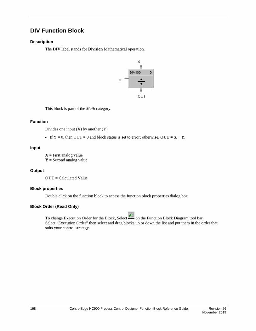
168 ControlEdge HC900 Process Control Designer Function Block Reference Guide Revision 26 November 2019
DIV Function Block
Description The DIV label stands for Division Mathematical operation.
This block is part of the Math category.
Function Divides one input (X) by another (Y)
• If Y = 0, then OUT = 0 and block status is set to error; otherwise, OUT = X ÷ Y.
Input X = First analog value Y = Second analog value
Output OUT = Calculated Value
Block properties Double click on the function block to access the function block properties dialog box.
Block Order (Read Only)
To change Execution Order for the Block, Select on the Function Block Diagram tool bar. Select ”Execution Order” then select and drag blocks up or down the list and put them in the order that suits your control strategy.

Revision 26 ControlEdge HC900 Process Control Designer Function Block Reference Guide 169 November 2019
Example Figure 33 shows a Function Block Diagram using a DIV function block.
Figure 33 DIV function block example

170 ControlEdge HC900 Process Control Designer Function Block Reference Guide Revision 26 November 2019
DLAY Function Block
Description The DLAY label stands for On Delay/Off Delay Timer.
This block is part of the Counters and Timers categories.
Function Block is configurable as On Delay or Off Delay.
For On Delay, output turns ON when timer expires.
For Off Delay, output turns OFF when timer expires.
Input TSPI - Delay time set point in seconds.
INPUT - Edge detection starts the timer. ON delay timer is triggered by rising edge of input. OFF delay timer is triggered by falling edge of input.
Output TSPO - Timer set point in seconds. Based on the TSPI pin at the point when the timer started. If TSPI changes after the timer starts, TSPI is ignored and TSPO maintains the current timer set point.
TREM - Remaining time in seconds; counts from TSPI down to 0.
TELPS - Elapsed time in seconds; counts from 0 to TSPI.
OUT - For On Delay, output turns ON when timer expires. For Off Delay, output turns OFF when timer expires.

Revision 26 ControlEdge HC900 Process Control Designer Function Block Reference Guide 171 November 2019
Block properties
Double click on the function block to access the function block properties dialog box.
Configuration parameters
Table 45 On Delay/Off Delay configuration parameters
Properties Group Parameter Index # Parameter Description Value or Selection
Timer Mode On Delay Off Delay
N/A On Delay: output turns ON after countdown from TSPI value.
Off Delay: output turns OFF after countdown from TSPI value.
The block’s graphic indicates the type of delay. See figures above.
Click Radio Button to select.

172 ControlEdge HC900 Process Control Designer Function Block Reference Guide Revision 26 November 2019
DO Function Block
Description The DO label stands for Digital Output.
This block is part of the I/O Blocks categories.
Function Provides a digital status from the algorithms and functions to physical logic output hardware. Each block requires a module and channel number during configuration. The output status may be inverted.
Input X = Input Status Signal
Output FAIL = Failed Output Indication - Module Error
Block properties
Double click on the function block to access the function block properties dialog box.

Revision 26 ControlEdge HC900 Process Control Designer Function Block Reference Guide 173 November 2019
Configuration parameters
Table 46 Digital output configuration parameters
Properties Group Parameter Index # Parameter Description Value or Selection
Address Rack N/A Rack Address of selected I/O Module
From 1 to 12
I/O Module Address of select I/O Module From 1 to 12
Channel Channel on selected I/O Module From 1 to 32 depending on the physical module type DC = 16 or 32 AC = 8 Relay = 4
Failsafe Failsafe ON N/A set the output of the block to OFF when failure is detected.
Click on radio button to select.
Failsafe OFF N/A set the output of the block to ON when failure is detected.
Click on radio button to select.
Failsafe HOLD
N/A hold the output at the last value just prior to the failure being detected.
Click on radio button to select.
1 If INVERT is selected, Invert IN before writing to output The slash will be present in the COIL symbol only when the invert box is selected on the dialog box. (See below.)
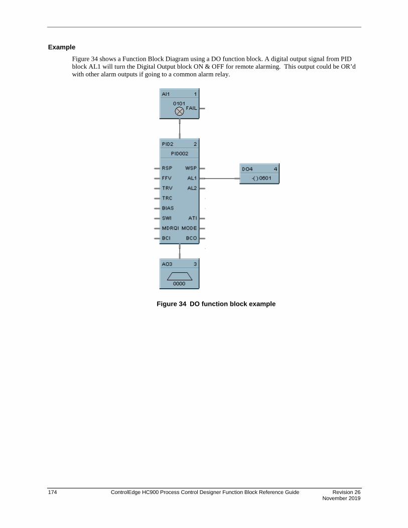
174 ControlEdge HC900 Process Control Designer Function Block Reference Guide Revision 26 November 2019
Example Figure 34 shows a Function Block Diagram using a DO function block. A digital output signal from PID block AL1 will turn the Digital Output block ON & OFF for remote alarming. This output could be OR’d with other alarm outputs if going to a common alarm relay.
Figure 34 DO function block example

Revision 26 ControlEdge HC900 Process Control Designer Function Block Reference Guide 175 November 2019
Digital Output Validated
Description The DO-V label stands for Digital Output Validated.
This block is part of the I/O Blocks category.
Function Provides a digital status from the algorithms and functions to physical logic output hardware. The digital status is fed back to DI feedback channel for validation. Each DO block and feedback DI requires a module and channel number during configuration. The output status for DO and feedback DI channel may be inverted.
Input X = Input Status Signal
^RSTRT = Restart Signal – When used, a positive (rising) input pulse releases OUT from its failsafe value and FAIL pin from its ON state. If ^RSTRT pin is left unconnected, the function block’s OUT and FAIL pins will not latch the status. This allows for the replacement or repair of the failed DO module or failure condition and operator controlled release.
DIS = Disable Signal – When used and made ON, disables the DO Channel and also results in disabling of ^RSTRT functionality. If DIS pin left unconnected or made OFF, results in Normal Operation i.e. it enables the function block.
Output OUT = Physical output value of function block
FAIL = Failed Output Indication – DO module has an error. OUT is set to failsafe (OFF - for safety worksheet and selectable for process worksheet).
FBFAIL = Feedback Fail – Feedback DI module fail. OUT continues to function without feedback validation.
VFAIL = Validation Fail – Input does not match output status i.e. the value read does not equal the value written. If DI module has an error, VFAIL will stay OFF. OUT continues to function without feedback validation.
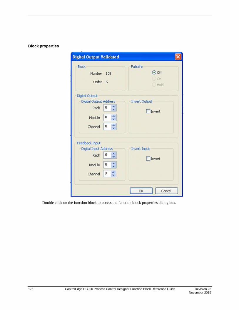
176 ControlEdge HC900 Process Control Designer Function Block Reference Guide Revision 26 November 2019
Block properties
Double click on the function block to access the function block properties dialog box.

Revision 26 ControlEdge HC900 Process Control Designer Function Block Reference Guide 177 November 2019
Configuration parameters
Properties Group
Parameter Index # Parameter Description Value or Selection
Address Rack N/A Rack address of selected DO module From 1 to 12
I/O Module Address of selected DO module From 1 to 12
Channel Channel number on selected DO module From 1 to 32, depending on the physical module type – DC or AC or Relay
Failsafe ON N/A Set the output of the block to ON when failure is detected
Click on radio button to select (Applicable to process worksheet only)
OFF N/A Set the output of the block to OFF when failure is detected
OFF (for safety worksheet)
Click on radio button to select (for process worksheet only)
HOLD N/A Hold the output at the last value just prior to the failure being detected
Click on radio button to select (Applicable to process worksheet only)
Invert Invert 1 If invert is selected, invert IN before writing to output. The slash will be present in the COIL symbol only when the invert box is selected on the dialog.
Address Rack N/A Rack address of selected feedback DI module
From 1 to 12
I/O Module Address of the selected feedback DI module
From 1 to 12
Channel Channel number on the selected feedback DI module
From 1 to 32
FB Invert FB Invert 4 If FB invert is selected, feedback value is an inverse of applied value.

178 ControlEdge HC900 Process Control Designer Function Block Reference Guide Revision 26 November 2019
Example Figure 35 below shows a function block diagram using a DO-V function block. A digital output signal (AL1) will turn the digital output for DO-V block ON and OFF for monitoring. The feedback fail (FBFAIL) and validation fail (VFAIL) are also used for monitoring the statuses. The connection to “RSTRT” pin ensures that the status on OUT and FAIL pins will remain latched, until a positive (rising) edge is detected on “RSTRT” pin.
Figure 35 DO-V function block

Revision 26 ControlEdge HC900 Process Control Designer Function Block Reference Guide 179 November 2019
8DO Function Block
Description The 8DO label stands for Eight Point Digital Outputs.
This block is part of the I/O Blocks categories.
Function Provides write access to any physical digital output. (All read at the same time) It minimizes the number of blocks required to configure all of the digital I/O required in the system. It provides a digital status from the algorithms and functions to physical logic output hardware. Each block output requires a module and channel number during configuration. The output status may be inverted.
Input IN D1 = Input Status Signal IN D2 = Input Status Signal IN D3 = Input Status Signal IN D4 = Input Status Signal IN D5 = Input Status Signal IN D6 = Input Status Signal IN D7 = Input Status Signal IN D8 = Input Status Signal
Output FAIL = Failed Output Indication - Module Error
Note: Write Coil instructions are not supported for outputs configured in the 8 DO FB in controllers of version 4.4xx or earlier. Use single DO FB when executing write coils to ControlEdge HC900 outputs.

180 ControlEdge HC900 Process Control Designer Function Block Reference Guide Revision 26 November 2019
Block properties
Double click on the function block to access the function block properties dialog box.
Configuration parameters
Table 47 Eight Digital output configuration parameters
Properties Group Parameter Index # Parameter Description Value or Selection
Output 1 through 8 Rack N/A Rack address of selected I/O Module
From 1 to 12
I/O Module Address of select I/O Module From 1 to 12
Channel Channel on selected I/O Module 1 to 8, 9 to 16, 17 to 24, 25 to 32
NOTE: If you don’t want to use an output pin, leave the
Module # and Channel # at 0.
Failsafe Failsafe ON N/A set the output of the block to OFF when failure is detected
Select from drop-down menu
Failsafe OFF N/A set the output of the block to ON when failure is detected
for each Output.
Failsafe HOLD
N/A hold the output at the last value just prior to the failure being detected
1 If INVERT is selected, Invert IN before writing to output The slash will be present in the COIL symbol only when the invert box is selected on the dialog box. (See below.)

Revision 26 ControlEdge HC900 Process Control Designer Function Block Reference Guide 181 November 2019
Example Figure 36 shows a Function Block Diagram using a 8 Point DO function block.
Figure 36 8 Point DO function block example
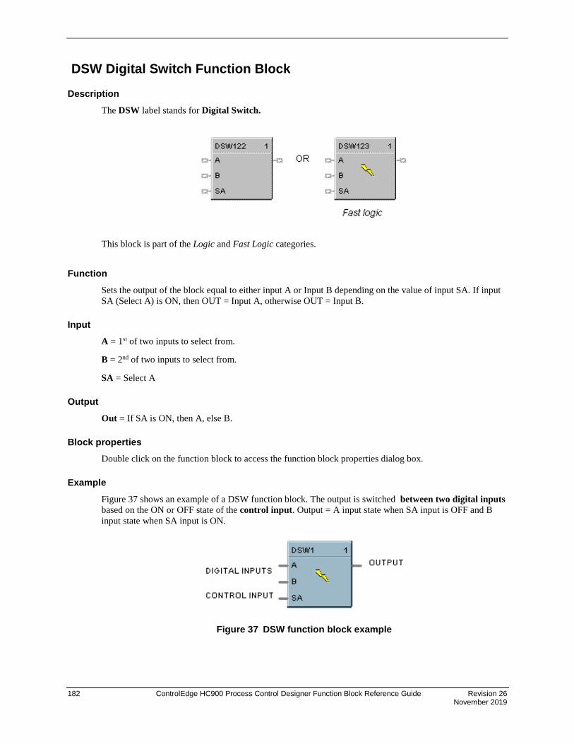
182 ControlEdge HC900 Process Control Designer Function Block Reference Guide Revision 26 November 2019
DSW Digital Switch Function Block
Description The DSW label stands for Digital Switch.
This block is part of the Logic and Fast Logic categories.
Function Sets the output of the block equal to either input A or Input B depending on the value of input SA. If input SA (Select A) is ON, then OUT = Input A, otherwise OUT = Input B.
Input A = 1st of two inputs to select from.
B = 2nd of two inputs to select from.
SA = Select A
Output Out = If SA is ON, then A, else B.
Block properties Double click on the function block to access the function block properties dialog box.
Example Figure 37 shows an example of a DSW function block. The output is switched between two digital inputs based on the ON or OFF state of the control input. Output = A input state when SA input is OFF and B input state when SA input is ON.
Figure 37 DSW function block example
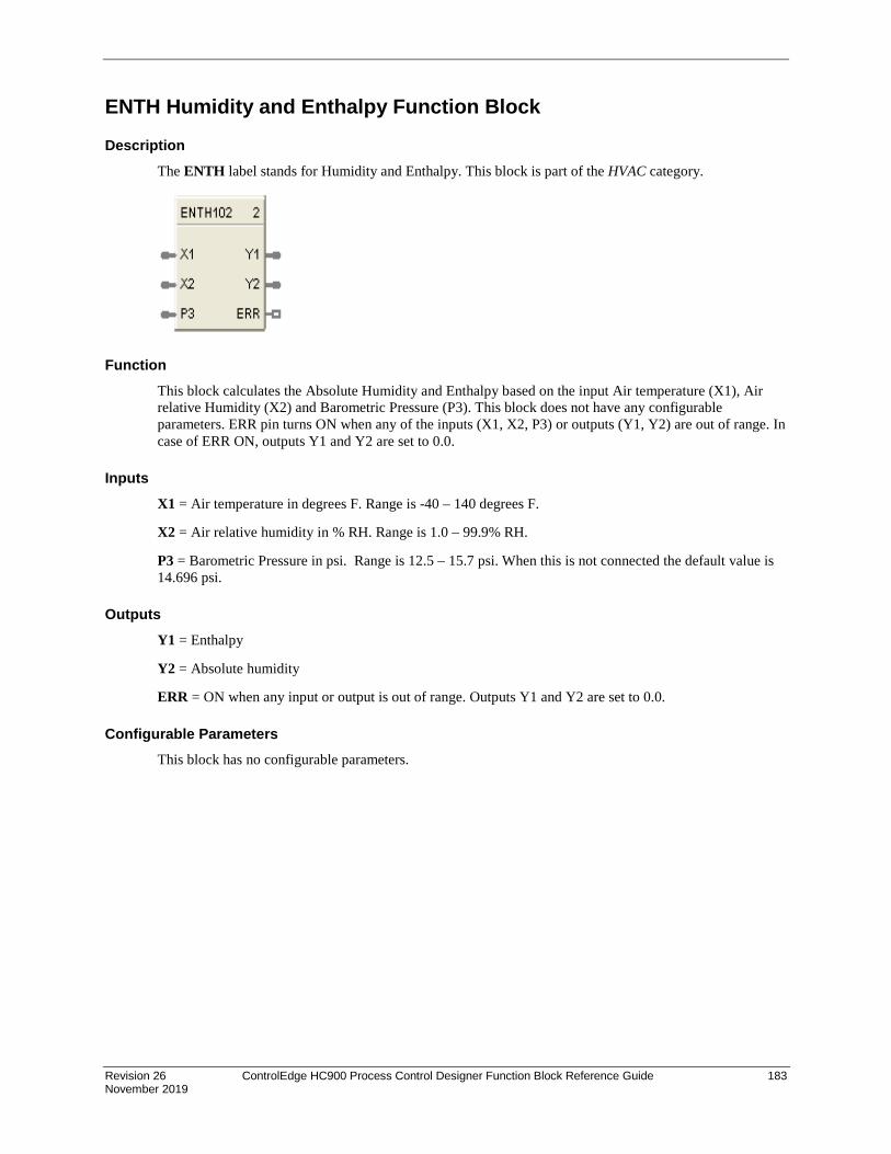
Revision 26 ControlEdge HC900 Process Control Designer Function Block Reference Guide 183 November 2019
ENTH Humidity and Enthalpy Function Block
Description The ENTH label stands for Humidity and Enthalpy. This block is part of the HVAC category.
Function This block calculates the Absolute Humidity and Enthalpy based on the input Air temperature (X1), Air relative Humidity (X2) and Barometric Pressure (P3). This block does not have any configurable parameters. ERR pin turns ON when any of the inputs (X1, X2, P3) or outputs (Y1, Y2) are out of range. In case of ERR ON, outputs Y1 and Y2 are set to 0.0.
Inputs X1 = Air temperature in degrees F. Range is -40 – 140 degrees F.
X2 = Air relative humidity in % RH. Range is 1.0 – 99.9% RH.
P3 = Barometric Pressure in psi. Range is 12.5 – 15.7 psi. When this is not connected the default value is 14.696 psi.
Outputs Y1 = Enthalpy
Y2 = Absolute humidity
ERR = ON when any input or output is out of range. Outputs Y1 and Y2 are set to 0.0.
Configurable Parameters This block has no configurable parameters.

184 ControlEdge HC900 Process Control Designer Function Block Reference Guide Revision 26 November 2019
Example Calculate enthalpy (0 – 100 btu/lb) and absolute humidity (0 to 100 lb/lb) as a function of air temperature, relative air humidity, and air pressure.
Figure 38 ENTH function block example
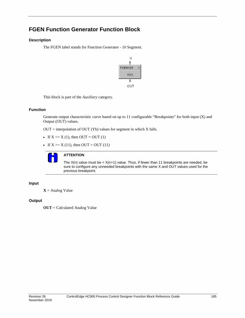
Revision 26 ControlEdge HC900 Process Control Designer Function Block Reference Guide 185 November 2019
FGEN Function Generator Function Block
Description The FGEN label stands for Function Generator - 10 Segment.
This block is part of the Auxiliary category.
Function Generate output characteristic curve based on up to 11 configurable “Breakpoints” for both input (X) and Output (OUT) values.
OUT = interpolation of OUT (Yb) values for segment in which X falls.
• If X <= X (1), then OUT = OUT (1)
• If X >= X (11), then OUT = OUT (11)
ATTENTION
The X(n) value must be < X(n+1) value. Thus, if fewer than 11 breakpoints are needed, be sure to configure any unneeded breakpoints with the same X and OUT values used for the previous breakpoint.
Input X = Analog Value
Output OUT = Calculated Analog Value

186 ControlEdge HC900 Process Control Designer Function Block Reference Guide Revision 26 November 2019
Block properties
Double click on the function block to access the function block properties dialog box.
Configuration parameters
Table 48 Function generator configuration parameters
Properties Group Parameter Index # Parameter Description Value or Selection
Block Block Order Execution order of the block. Read Only. To change block order, right-click on a Function Block and select Execution Order.
Breakpoints X1 0 X-value at Input Breakpoint 1 –99999 to 999999
X2 1 X-value at Input Breakpoint 2 –99999 to 999999
X3 2 X-value at Input Breakpoint 3 –99999 to 999999
X4 3 X-value at Input Breakpoint 4 –99999 to 999999
X5 4 X-value at Input Breakpoint 5 –99999 to 999999
X6 5 X-value at Input Breakpoint 6 –99999 to 999999
X7 6 X-value at Input Breakpoint 7 –99999 to 999999
X8 7 X-value at Input Breakpoint 8 –99999 to 999999
X9 8 X-value at Input Breakpoint 9 –99999 to 999999
X10 9 X-value at Input Breakpoint 10 –99999 to 999999

Revision 26 ControlEdge HC900 Process Control Designer Function Block Reference Guide 187 November 2019
Properties Group Parameter Index # Parameter Description Value or Selection
X11 10 X-value at Input Breakpoint 11 –99999 to 999999
Y1 11 Y-value at Output Breakpoint 1 –99999 to 999999
Y2 12 Y-value at Output Breakpoint 2 –99999 to 999999
Y3 13 Y-value at Output Breakpoint 3 –99999 to 999999
Y4 14 Y-value at Output Breakpoint 4 –99999 to 999999
Y5 15 Y-value at Output Breakpoint 5 –99999 to 999999
Y6 16 Y-value at Output Breakpoint 6 –99999 to 999999
Y7 17 Y-value at Output Breakpoint 7 –99999 to 999999
Y8 18 Y-value at Output Breakpoint 8 –99999 to 999999
Y9 19 Y-value at Output Breakpoint 9 –99999 to 999999
Y10 20 Y-value at Output Breakpoint 10 –99999 to 999999
Y11 21 Y-value at Output Breakpoint 11 –99999 to 999999
Clear All Button Click on button to clear all breakpoint values.
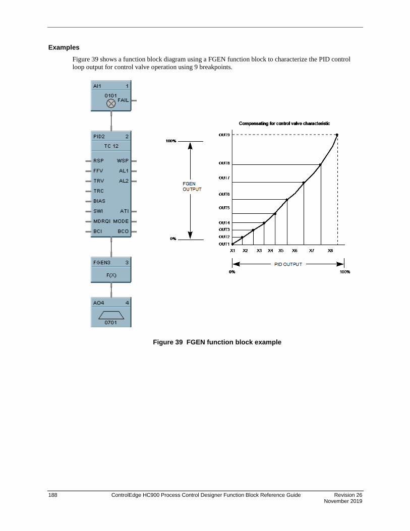
188 ControlEdge HC900 Process Control Designer Function Block Reference Guide Revision 26 November 2019
Examples Figure 39 shows a function block diagram using a FGEN function block to characterize the PID control loop output for control valve operation using 9 breakpoints.
Figure 39 FGEN function block example

Revision 26 ControlEdge HC900 Process Control Designer Function Block Reference Guide 189 November 2019
FI Frequency Input
Description The FI label stands for Frequency Input.
This block is part of the I/O Blocks category.
Function The function is used for measuring speed and rate. It reads a single frequency channel from a Pulse/Frequency/Quadrature input module. The signal is scaled from the selected frequency span to the selected output range in engineering units, providing an output value in engineering units.
The input signal is rejected if it is below a selected pulse width. The frequency of pulses above this width must be within the range specified by Pulse Width (Range); otherwise the output goes to failsafe and a failure-to-convert error occurs.
Input ENABL = Level input to enable block. Input is ignored if not connected and default state is enabled. If block is disabled the output goes to zero.
Output FAIL = A Boolean value that turns ON when the Pulse/Frequency/Quadrature input module reports a failure.
OUT = The frequency input value scaled to engineering units (after filters, ranges, bias, or failsafe conditions have been applied).
( ) Bias Low EU OutputLow EU Output - High EU OutputLow SpanFrequency - High SpanFrequency
Low SpanFrequency - InFrequency OUT * += +
The generic forcing of outputs is permitted.

190 ControlEdge HC900 Process Control Designer Function Block Reference Guide Revision 26 November 2019
Example Say you configure the block as follows.
Pulse Width (Range) = 500µsec (10Hz-500Hz)
Frequency Span Low = 50Hz
Frequency Span High = 450Hz
Output range in EU = 0 - 100
Bias = 8
Failsafe = Upscale (upper output range)
Assume the module is receiving a 255Hz signal, including noise. Assume 2% of pulses are noise, that is, are less than the minimum pulse width 500 µsec. The block rejects this 2% and does not count them in the frequency. The remaining 98% valid pulses are counted, which is an effective signal of 250Hz. From the output equation above,
OUT = [(250–50) / (450-50)] * (100 – 0) + 0 + 8
= [200/400] * 100 + 8
= 0.5 * 100 + 8
= 50 + 8
= 58 EU
If the frequency of the effective signal (>500 µsec pulse width) changes to outside the specified range of 10-500Hz, a failure-to-convert error occurs and the output goes to failsafe, in this case upscale (100).

Revision 26 ControlEdge HC900 Process Control Designer Function Block Reference Guide 191 November 2019
Configurable Parameters
Table 49 Frequency Input configuration parameters Properties Group Parameter Index # Parameter Description Value or Selection Block Order N/A Execution Order for Block
Read Only. To change block order, right-click on a Function Block and select Execution Order.
Address Rack 0 This is the rack address of the PFQ module.
Enter a value: from 1 to 12.
Module 0 Module address of the PFQ module. Enter a value: from 1 to 12.
Channel 0 Channel on selected Module. Enter a value: from 1 to 4
Frequency Span Set High Input (Hz)
7 High frequency value of the input device. Exceeding this limit causes an over-range error.
Enter value in Hz.
Set Low Input (Hz)
8 Low frequency value of the input device. Exceeding this limit causes an under -range error.
Enter value in Hz.
Output Range in EU
High (EU) 5 High range value. Frequency span in Hz is scaled to the output range in EU.
Enter value in EU.
Low (EU) 6 Low range value. Frequency span in Hz is scaled to the output range in EU.
Enter value in EU.
Settings Bias 2 Bias value added to the output. Enter value in EU.
Pulse Width (Range)
9 The input signal is rejected if it is below this pulse width. The frequency of pulses above this width must be in this frequency range; otherwise the output goes to failsafe and a failure-to-convert error occurs.
500µsec (10Hz-500Hz) 50µsec (10Hz-5KHz) 2.5µsec (10Hz-100KHz)
Filter Time (sec)
1 Filter time constant in seconds. Enter value in seconds.
Failsafe Use Value 3 When FAIL is ON output is set to this value.
Click to select, enter a value.
Up scale 4 When FAIL is ON output is set to Upper Range Limit.
Click to select.
Down scale 4 When FAIL is ON output is set to Lower Range Limit.
Click to select.
HOLD 4 When FAIL is ON output is held. Click to select.
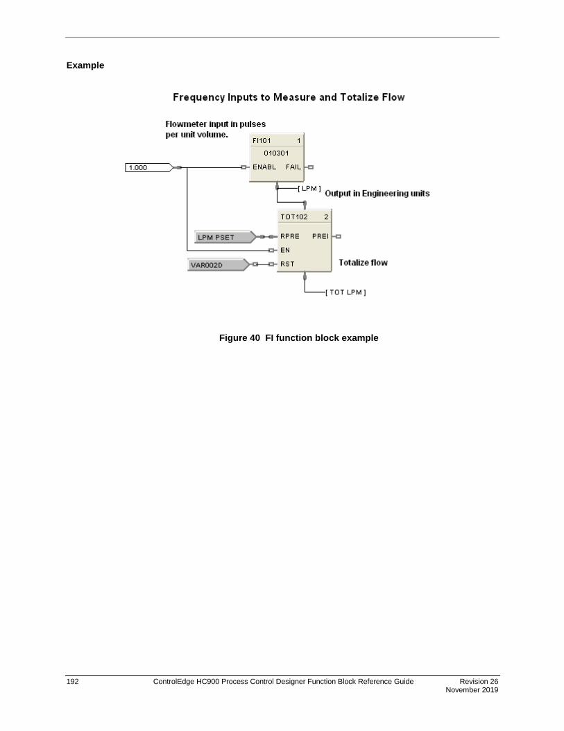
192 ControlEdge HC900 Process Control Designer Function Block Reference Guide Revision 26 November 2019
Example
Figure 40 FI function block example

Revision 26 ControlEdge HC900 Process Control Designer Function Block Reference Guide 193 November 2019
FMON Fault Monitor Function Block
Description The FMON label stands for Fault Monitor.
This block is part of the Alarm/Monitory category.
Function The reaction on detected faults is configurable depending on the applications for which the ControlEdge HC900 is used. The FMON block has a fault clear input pin used for clearing all the faults generated and a fault output pin to display the selected diagnostic fail status. Each FMON function block requires a rack number, module number and a corresponding diagnostic to be selected during configuration, depending on the type of diagnostic group selected.
The rack number is specified as: 1 = Rack#1 (Main Rack)
2 = Rack#2 (Expansion Rack)
3 = Rack#3 (Expansion Rack)
4 = Rack#4 (Expansion Rack)
5 = Rack #5 (Expansion Rack)
Inputs CLRFLT - ON = Clears all the existing faults.
- OFF = Leaves the existing faults in the current status.
Outputs DIAG FAIL = Fail status of the selected diagnostic.

194 ControlEdge HC900 Process Control Designer Function Block Reference Guide Revision 26 November 2019
Block Properties
Double click on the function block to access the function block properties dialog box .
Configurable Parameters Properties
Group Parameter Index # Parameter Description Value or Selection
Address Rack
N/A
Rack address of selected DO module
Enter a value: from 1 to 12
I/O Module Address of selected module Enter a value: from 1 to 12
Diagnostics
Controller Diagnostics
N/A
Controller diagnostics group
Select one of the group diagnostics
Rack Diagnostics Rack diagnostics group
Module Diagnostics Module diagnostics group
Set Diagnostics
Select Diagnostic
N/A Holds the diagnostic of the
selected diagnostics group
Select one of the group diagnostic from the drop down list

Revision 26 ControlEdge HC900 Process Control Designer Function Block Reference Guide 195 November 2019
Fault Monitor Block –Diagnostics List
Diagnostics Type Diagnostics Possible Cause
Controller
E1 Port E1 port failure.
E2 Port E2 port failure.
IO Port IO port failure.
Serial1 Serial port1 failure
Serial2 Serial port2 failure
R-Link Failure of the redundancy link between the lead CPU and the redundant CPU
Watchdog Watchdog reset resulting from software failure.
Battery1 Controller’s battery1 Low
Battery2 Controller’s battery2 Low
Mode Switch Failure in the switch reading
RTC Fail Real Time Clock failed
Rack Diagnostics
Any Module Error One of the module diagnostics in the associated rack is set to WRONG MODULE, MODULE NO COMM (if the communications is failing due to the module not installed), BAD MODULE, or BAD CHANNEL.
Any Module High Temperature
one of the two CJs on the module is indicating a temperature reading greater than 70 degrees C.
No IO Communication The Main CPU is unable to successfully communicate to an expansion rack that is in its configuration.
Bad Scanner Version The Main CPU determined that its software is not compatible with the scanner module.
Power Supply The rack diagnostics within Fault monitor block indicates status of redundant power supplies in case of failure or faults. The output of this block can be sent as a input to a HMI for operator intervention or other input block
Module Diagnostics
AI High CJ Temperature AI module’s one of the two CJs on the module is indicating a temperature reading greater than 70 degrees C.
Wrong Module Installed The module does not agree with the module required for the control scenario.
No Module Communication
Main CPU is unable to communicate to the module for one of the following reasons:
Module is not installed
The module cannot communicate with the controller CPU or the expansion rack CPU because of a backplane problem. Module is on an expansion rack and the expansion rack communications are failing
Bad Channel One or more channels in the module are bad.
Bad Module Module is bad. Module LED flashes to indicate the problem.

196 ControlEdge HC900 Process Control Designer Function Block Reference Guide Revision 26 November 2019
FRCP Force Present Function Block Description
The FRCP label stands for Force Present. . There are two versions of the block. For SIL certified devices, the block has two output pins, whereas non SIL certified devices have single output pin. The block dimensions also vary for SIL and non SIL devices. This block is part of the Alarms/Monitors category. It is available for Normal Scan only.
Function block for C30S, C50S, C70S, C75S device types.
Function block for C30, C50, C70, C75 device types.
This block is part of the Alarm/Monitor category. It is available for Normal Scan only.
Function
Output indicates the presence of any forced blocks in the controller. Input can clear all forces and prevent new forces.
Inputs
RST - When ON clears all existing forces and prevents any new force requests, notifying user that forcing is disabled. Does not affect the Force Present block itself. When OFF, leaves forces in current state. No connection to this pin is the same as OFF.
Outputs
FORCED - ON = One or more forces exist in the controller.
OFF = No forces exist in the controller.
PROCESS - ON = One or more forces exist in the controller on Process Worksheets.
OFF = No forces exist in the controller on Process Worksheets.
SAFETY - ON = One or more forces exist in the controller on Safety Worksheets.
OFF = No forces exist in the controller on Safety Worksheets.

Revision 26 ControlEdge HC900 Process Control Designer Function Block Reference Guide 197 November 2019
Block properties
Double click on the function block to access the function block properties dialog box.
Configuration parameters
Table 50 Force Present configuration parameters
Properties Group Parameter Index # Parameter Description Value or Selection
Block Order N/A Execution Order for Block
Read Only. To change block order, right-click on a Function Block and select Execution Order.
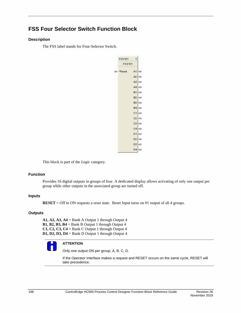
198 ControlEdge HC900 Process Control Designer Function Block Reference Guide Revision 26 November 2019
FSS Four Selector Switch Function Block
Description The FSS label stands for Four-Selector Switch.
This block is part of the Logic category.
Function Provides 16 digital outputs in groups of four. A dedicated display allows activating of only one output per group while other outputs in the associated group are turned off.
Inputs RESET = Off to ON requests a reset state. Reset Input turns on #1 output of all 4 groups.
Outputs A1, A2, A3, A4 = Bank A Output 1 through Output 4 B1, B2, B3, B4 = Bank B Output 1 through Output 4 C1, C2, C3, C4 = Bank C Output 1 through Output 4 D1, D2, D3, D4 = Bank D Output 1 through Output 4
ATTENTION
Only one output ON per group, A, B, C, D.
If the Operator Interface makes a request and RESET occurs on the same cycle, RESET will take precedence.

Revision 26 ControlEdge HC900 Process Control Designer Function Block Reference Guide 199 November 2019
Block properties
Double click on the function block to access the function block properties dialog box.
Configuration parameters
Table 51 Four Selector Switch (FSS) configuration parameters for operator interface display
Properties Group Parameter Index # Parameter Description Value or Selection
Name Enter a Tag Name for the block 16 Characters (ASCII characters only)
Title Enter a Title for the block 24 characters
Bank x Labels
X = A, B, C, or D
Descriptor Enter a Descriptor for Bank x Labels 16 characters (ASCII characters only)
Bank x Label 1 Enter a label name for display 6 characters
Bank x Label 2 Enter a label name for display 6 characters
Bank x Label 3 Enter a label name for display 6 characters
Bank x Label 4 Enter a label name for display 6 characters

200 ControlEdge HC900 Process Control Designer Function Block Reference Guide Revision 26 November 2019
Example Figure 41 shows a Four Selector Switch (FSS) function block and its associated display.
ATTENTION
The Four Selector group display is directly associated with the Four Selector Function Block. Pressing O/I Keys F1 through F4 call up a dialog box that allows changes to the output selection for the associated block.
Figure 41 FSS function block example

Revision 26 ControlEdge HC900 Process Control Designer Function Block Reference Guide 201 November 2019
FSYS Fast Logic System Monitor
Description The FSYS label stands for Fast Scan System Status. This block is part of the Alarm/Monitor Blocks category.
Function This function block provides read access to controller status values including those related to the Fast Scan execution cycle. (To access status values relating to the Normal Scan execution cycle see the ASYS function block.) The outputs may be connected to function block inputs. The outputs may also be connected to signal tags for operator interface monitoring. The Fast Scan System Status block is assigned block number 2.
Versions The status information available to be monitored for the fast scan execution system depends on both the controller type and the revision of software executing on the controller. As a result, there are different versions of the FSYS block and when you drag and drop this block onto a configuration worksheet the graphic may look a little different than the one shown above. The Process Control Designer will automatically select the correct version of the block based on the controller type and software revision selected for each configuration file.
The graphic shown above is for the most advanced version of the block and earlier versions may have fewer outputs, different output types and/or different output ordering. Where applicable, the differences are described in the table below for each output.
Restrictions There can be only one instance of the FSYS function block within a configuration.

202 ControlEdge HC900 Process Control Designer Function Block Reference Guide Revision 26 November 2019
Table 52 Fast logic system status block outputs
Output Description
NEWSTART ON for one full cycle of control block execution, following a New start of the system. For example: starting after a change from program to run.
RESTART ON for one full cycle of control block execution, following power up. [Warm Start] ALM_ACTIV Alarm Active is ON if any operator panel alarm is ON. ALM_UNACK Alarm unacknowledged is ON if any operator panel’s alarm is unacknowledged. HWOK Hardware OK is ON if there are no faults. HWOK is set to off when a Rack Monitor Block’s
RACK OK pin is off. LOWBTRY Low Battery is ON if the battery is low, Off when battery is good. HITEMP High CJ Temperature is ON if the CJ temperature is high on any rack. MSTR_FAIL Communications Failure is ON when Modbus master diagnostic is not good. BAD_BLOCK Provides an indication of whether or not there are any blocks in the fast scan execution that are
not operating properly. Any function block monitor window which indicates a block status other than "OK" is considered a Bad Block. For example: forced outputs (analog or digital), math errors (divide by zero), un-configured I/O blocks (rack/slot/channel) and PID blocks with a PV over/under the configured range limits.
The level of indication provided depends on the software revision:
Revision 6.0:
This pin is an analog output which provides the block number of the first bad block in the fast scan configuration, as per execution order. Refer also to the BBLK_CNT output below.
Revision 4.402 and earlier:
This pin is a digital output which provides simple ON/Off indication of at least one bad block in the fast scan execution logic. The BBLK_CNT output below does not exist in these versions.
LOCKED Controller locked in current mode by switch position. RSV AVAIL Available for C75 and C75S redundant CPU controllers only.
ON when the Reserve CPU is available for failover. OFF when the Reserve CPU is unavailable for failover. On other controllers this pin may be missing or may be labeled as "N/A" and serves only as a placeholder, depending on the revision of the software.
BBLK_CNT Available in software revision 6.0 and higher.
The number of bad blocks present in the fast scan execution logic. Refer to the BAD_BLOCK output above for the definition of a bad block.

Revision 26 ControlEdge HC900 Process Control Designer Function Block Reference Guide 203 November 2019
HLLM High Low Limiter Function Block
Description The HLLM label stands for High Low limiter.
This block is part of the Auxiliary category.
Function Provide high-low limit for an analog (X) value.
Turns ON H or L digital output if input exceeds or falls below set limits.
• If X < or = Low Limit value, then: OUT = LoLlM; L = ON; H = OFF.
• If X > or = High Limit value, then: OUT = HiLlM; L = OFF; H= ON.
• If X > Low Limit value and < high Limit value, then: OUT = X; L = OFF; H = OFF.
Input X = Analog Value
Output OUT = Analog value within limits
L = Low Limit digital indication
H= High Limit digital indication
Block properties
Double click on the function block to access the function block properties dialog box.

204 ControlEdge HC900 Process Control Designer Function Block Reference Guide Revision 26 November 2019
Configuration parameters
Table 53 High low limit configuration parameters
Properties Group Parameter Index # Parameter Description Value or Selection
Set Limits High Limit 0 High limit value for analog (X) value –99999 to 999999
Low Limit 1 Low limit value for analog (X) value –99999 to 999999
Example Figure 42 shows a Function Block Diagram using an HLLM function block to provide a remote setpoint signal within specified limits to a PID Control Loop.
Figure 42 HLLM function block example
X Input
Output
X HI
X LO
HI*
LO*
X
OUT

Revision 26 ControlEdge HC900 Process Control Designer Function Block Reference Guide 205 November 2019
HMON High Monitor Function Block
Description The HMON label stands for High Monitor.
This block is part of the Alarm/Monitor category.
Function Monitors two analog input values (X and Y) and turns ON a digital output if X exceeds Y. A hysteresis adjustment is provided to prevent output cycling.
• If X > Y, then OUT = ON.
• If X < or = (Y – Hysteresis), then OUT = OFF.
• If (Y – Hysteresis) < X < Y, then OUT = Previous State.
Input X = Analog value.
Y = Analog value
Output OUT = Digital signal
Block properties
Double click on the function block to access the function block properties dialog box.

206 ControlEdge HC900 Process Control Designer Function Block Reference Guide Revision 26 November 2019
Configuration parameters
Table 54 High monitor function block configuration parameters
Properties Group Parameter Index # Parameter Description Value or Selection
Set Properties Hysteresis 0 An adjustable overlap of the On/Off states of the output.
0 to the Span of Y input in Engineering units.
Example Figure 43 shows a Function Block Diagram using an HMON function block. It shows a typical output signal response provided by an HMON function block.
Figure 43 HMON function block example

Revision 26 ControlEdge HC900 Process Control Designer Function Block Reference Guide 207 November 2019
HOA Hand/Off/Auto Switch Function Block
Description The HOA label stands for Hand/Off/Auto Switch.
This block is part of the Auxiliary category.
Function The Hand – Off – Auto (HOA) switch function block permits state change requests from a Local Operator Interface or a Remote source. The block states are: BYPASS (external manual operation of a device), HAND (manual operation from an operator interface), AUTO (default – requests are operated automatically), or OFF (relay to be switched to Bypass, Hand, or Auto)
The HOA switch is also used with the Device Control (DC) function block to comprise a Pump Control algorithm which is used to manipulate the state of a controlled device (pump).
Each configuration is limited to a maximum of 16 HOA function blocks. Forcing of outputs is NOT permitted within this block.
Input REQI = If the current state of the block is AUTO, then REQO output (on/off) equals the REQI input (on/off).
BYPS = If ON, the REQO output is forced off and any state change requests are ignored. If OFF, the block returns to its previous state (Hand, Off, Auto).
Output HAND = ON when the block is in the HAND state, else OFF. Device is in manual operation from an operator interface; prevents automatic operation; this state forces the REQO output ON.
AUTO = On when block is in AUTO state, else OFF. Requests are operated automatically.
REQO = This is ON when in the HAND state, or when in the AUTO state and the REQI input signal is ON. OFF when in the OFF or BYPASS state.
Note. Both HAND and AUTO are OFF in the OFF and BYPASS states.
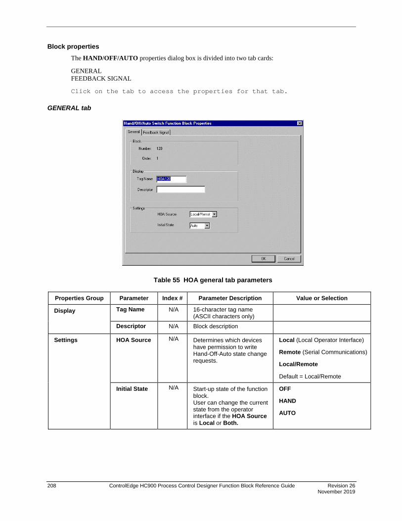
208 ControlEdge HC900 Process Control Designer Function Block Reference Guide Revision 26 November 2019
Block properties The HAND/OFF/AUTO properties dialog box is divided into two tab cards:
GENERAL FEEDBACK SIGNAL
Click on the tab to access the properties for that tab.
GENERAL tab
Table 55 HOA general tab parameters
Properties Group Parameter Index # Parameter Description Value or Selection
Display Tag Name N/A 16-character tag name (ASCII characters only)
Descriptor N/A Block description
Settings HOA Source N/A Determines which devices have permission to write Hand-Off-Auto state change requests.
Local (Local Operator Interface)
Remote (Serial Communications)
Local/Remote
Default = Local/Remote
Initial State N/A Start-up state of the function block. User can change the current state from the operator interface if the HOA Source is Local or Both.
OFF
HAND
AUTO

Revision 26 ControlEdge HC900 Process Control Designer Function Block Reference Guide 209 November 2019
FEEDBACK SIGNAL tab The feedback signal is used for display purposes.
When the HOA block is used in conjunction with a Device Control (DC) block, the feedback is typically referenced to the (STI) status output pin of the DC block. The sample text shown in Table 56 would correspond to the states of the DC block.
To select a Feedback signal and to define state text for the enumerated value of the feedback signal, proceed with the sequence 1 through 3 below.
Table 56 HOA feedback signal tab parameters
Sequence Number
Parameter Field
Action Selections Comments
1
Analog Signal Tag List
Click on a signal tag in the list
Select from all configured Analog Signal tags listed
2
Select/Delete Signal
Click “Select” at the bottom of the “Analog Signal Tag List” to place highlighted signal tag into the “Selected Signal” field
The selection is placed in the Selected Signal field on the dialog box.
Click on “Delete Signal” at the bottom of the “Analog Signal Tag List” to remove a signal tag from field.

210 ControlEdge HC900 Process Control Designer Function Block Reference Guide Revision 26 November 2019
Sequence Number
Parameter Field
Action Selections Comments
3
States
The state text will be selected for the display based on the numerical value (0 through 8) of the specified analog signal.
Default Text
????????
READY
PRESTART
STARTING
RUNNING
STOPPING
FAILED
DISABLED
STATE 8
Enumerated value of selected signal
0
1
2
3
4
5
6
7
8
You can highlight any state and change the text to whatever you desire for that state.
???????? = Block not used

Revision 26 ControlEdge HC900 Process Control Designer Function Block Reference Guide 211 November 2019
Example Figure 44 shows a Function Block Diagram using an HOA function block in conjunction with a Device Control (DC) block and an external HOA switch for pump control. The level signal input and Compare (CMPR) function are used to determine pump On/Off demand.
Figure 44 HOA function block example

212 ControlEdge HC900 Process Control Designer Function Block Reference Guide Revision 26 November 2019
HSEL High Selector Function Block
Description The HSEL label stands for High Selector.
This block is part of the Signal Selectors category.
Function Selects higher of two analog input values (X and Y) for output. Indicates when Y is higher than X.
• If X > or = Y, then: OUT = X; YHI = OFF.
• If X < Y, then: OUT = Y; YHI = ON.
Input X = Analog value Y = Analog value
Output OUT = Higher analog value YHI = Digital signal. (ON when Y>X.)
Block properties Double click on the function block to access the function block properties dialog box.

Revision 26 ControlEdge HC900 Process Control Designer Function Block Reference Guide 213 November 2019
Example Figure 45 shows a Function Block Diagram using an HSEL function block to monitor two analog inputs to activate an alarm signal tag.
Figure 45 HSEL Function Block Example

214 ControlEdge HC900 Process Control Designer Function Block Reference Guide Revision 26 November 2019
IMM - IO Module Monitor Block
Description The IMM label stands for IO Module Monitor Block.
This block is part of the Alarm/Monitor category.
Function The IMM block has a fault clear input pin used for clearing all the faults of module it is configured for. Each IMM function block requires a rack number, module number. This block provides module diagnostics. This can be used in place of FM (Fault monitor) block also.
Note: Field current shown on the block monitor window has an offset of 1-20mA.
Inputs CLRFLT – OFF to ON = Clears all the existing faults of module.
- ON = Leaves the existing faults in the current status.
- OFF = Leaves the existing faults in the current status.
Outputs AIHGCJTEMP = Analog input High CJ Temperature Fault (applies to only UAI module)
MISMATCH = Module mismatch fault
NOCOMM = No communication fault
BADCHANNEL = Bad channel fault
BADMODULE = Bad module fault
OVERTEMP = Over temperature fault (applies to only UIO module)
FLDOVERCRNT = Field Over Current Fault (applies to only UIO module)
FLDVLTFLT= Field Volt Fault (applies to only UIO module)
DIAGFAIL = Fail Status of diagnostics (applies to only UIO module)

Revision 26 ControlEdge HC900 Process Control Designer Function Block Reference Guide 215 November 2019
Block Properties
Double click on the function block to access the function block properties dialog box.
Configurable Parameters
Properties Group Parameter Index # Parameter Description Value or Selection
Address Rack
N/A Rack address of selected DO module Enter a value:
from 1 to 12
I/O Module Address of selected module Enter a value: from 1 to 12
Example Figure 46 IMM function blockshows a Function Block Diagram using an IMM function block
Figure 46 IMM function block

216 ControlEdge HC900 Process Control Designer Function Block Reference Guide Revision 26 November 2019
LDLG Lead/Lag Function Block
Description The LDLG label stands for Lead/Lag.
This block is part of the Auxiliary category.
Function Modifies an analog input value (X) to include LEAD (T2) and LAG (T1) time constants of from 0 to 99 minutes, when a digital input (EN) is ON.
• If EN = ON, then:
s = Laplace operator
If T1 = 0, then:
last X = Input value from execution cycle.
t = Duration of previous cycle time in minutes.
If T2 = 0, then the block functions as a digital lag filter.
• If EN = OFF, or initial start, then: OUT = X.
Inputs X = Analog value (Primary Input)
EN = Digital signal (Enable)
Output OUT = Analog value as modified
OUT =1 + sT21 + sT1
x X
OUT = last X + T2t
(X - last X)

Revision 26 ControlEdge HC900 Process Control Designer Function Block Reference Guide 217 November 2019
Block properties
Double click on the function block to access the function block properties dialog box.
Configuration parameters
Table 57 Lead lag configuration parameters
Properties Group Parameter Index # Parameter Description Value or Selection
Time Constants Lag Time (min) 0 T1 - Lag Time Constant 0.00 to 99.00 minutes
Lead Time (min)
1 T2 - Lead Time Constant
NOTE: If T2 is set to 0, function becomes a lag filter.
0.00 to 99.00 minutes

218 ControlEdge HC900 Process Control Designer Function Block Reference Guide Revision 26 November 2019
Example Figure 47 shows a Function Block Diagram using an LDLG function block to modify the PV signal for the remote setpoint input of the PID control loop.
Figure 47 LDLG function block example

Revision 26 ControlEdge HC900 Process Control Designer Function Block Reference Guide 219 November 2019
LMON Low Monitor Function Block
Description The LMON label stands for Low Monitor.
This block is part of the Alarm/Monitor category.
Function Monitors two analog input values (X and Y), and turns ON a digital output if X is less than Y. A hysteresis adjustment is provided to prevent output cycling.
• If X < Y, then: OUT = ON.
• If X > or = (Y + Hysteresis), then: OUT = OFF.
• If (Y + Hysteresis) > X > Y, then: OUT = Previous State.
Input X = Analog value.
Y = Analog value
Output OUT = Digital signal
Block properties
Double click on the function block to access the function block properties dialog box.

220 ControlEdge HC900 Process Control Designer Function Block Reference Guide Revision 26 November 2019
Configuration parameters
Table 58 Low monitor function block configuration parameters
Properties Group Parameter Index # Parameter Description Value or Selection
Set Properties Hysteresis 0 An adjustable overlap of the On/Off states of the output.
0 to the Span of Y input in Engineering units.
Example Figure 48 shows a Function Block Diagram using an LMON function block. It shows a typical output response provided by a LMON function block.
Figure 48 LMON function block example

Revision 26 ControlEdge HC900 Process Control Designer Function Block Reference Guide 221 November 2019
LPSW Loop Switch Function Block
Description The LPSW label stands for Loop Switch.
This block is part of the Loops category.
Function Digital interface to control loops to initiate autotuning, change control action, force bumpless transfer, select tuning set. It connects to a PID, TPSC, or CARB function block.
Inputs ^ATC = Autotune Command (OFF to ON initiates Autotuning)**
CACT = Change Control Action (ON changes Control Action)
^FBT = Force Bumpless Transfer (OFF to ON Forces Bumpless Transfer)** Performs the same function that occurs when the loop changes from Manual to Automatic mode. The loop will re-calculate the integral term to normalize the PID algorithm to the current PV and SP. You could use this input to correct for a reset wind-up condition that might have occurred when an input sensor failed and was replaced/corrected.
^TUN1 = Tune Set 1 (OFF to ON switches to Tune Set 1*)**
^TUN2 = Tune Set 2 (OFF to ON switches to Tune Set 2)**
* Switch to Tune Set 1 overrides concurrent command to switch to Tune Set 2
** Not available for ON/OFF function Block
Output SWO = The output of this block must connect to the SW1 input of a PID, CARB, and TPSC function block.
Note: Transitions of the SWO output are not sensed when a PID loop is in Manual mode.
Block properties Double click on the function block to access the function block properties dialog box.

222 ControlEdge HC900 Process Control Designer Function Block Reference Guide Revision 26 November 2019
Example Figure 49 shows a Function Block Diagram using an LPSW function block
Function: Digital interface to initiate:
• Autotuning
• Change Control Action: Direct/Reverse Action
• Force Bumpless Transfer (rebalance the algorithm)
• Select Tuning Set #1
• Select Tuning Set #2
Figure 49 LPSW function block example

Revision 26 ControlEdge HC900 Process Control Designer Function Block Reference Guide 223 November 2019
LSEL Low Selector Function Block
Description The LSEL label stands for Low Selector.
This block is part of the Signal Selectors category. Function
Selects lower of two analog input values (X & Y) for output.
Indicates when Y is lower than X.
• If X < or = Y, then: OUT = X; YLO = OFF.
• If X > Y, then: OUT = Y; YLO = ON.
Input X = Analog value Y = Analog value
Output OUT = Lower analog value YLO = Digital signal (ON when Y<X)
Block properties Double click on the function block to access the function block properties dialog box.
Example Figure 50 shows a Function Block Diagram using an LSEL function block to monitor two analog inputs to activate an alarm signal tag.
Figure 50 LSEL function block example
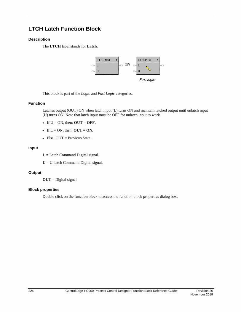
224 ControlEdge HC900 Process Control Designer Function Block Reference Guide Revision 26 November 2019
LTCH Latch Function Block
Description The LTCH label stands for Latch.
This block is part of the Logic and Fast Logic categories.
Function Latches output (OUT) ON when latch input (L) turns ON and maintain latched output until unlatch input (U) turns ON. Note that latch input must be OFF for unlatch input to work.
• If U = ON, then: OUT = OFF.
• If L = ON, then: OUT = ON.
• Else, OUT = Previous State.
Input L = Latch Command Digital signal.
U = Unlatch Command Digital signal.
Output OUT = Digital signal
Block properties Double click on the function block to access the function block properties dialog box.

Revision 26 ControlEdge HC900 Process Control Designer Function Block Reference Guide 225 November 2019
Example Figure 51 shows a Function Block Diagram using an LTCH function block.
Figure 51 LTCH function block example

226 ControlEdge HC900 Process Control Designer Function Block Reference Guide Revision 26 November 2019
MATH Function Block
Description The MATH label stands for Free Form Math.
This block is part of the Math category.
Function Read inputs A through H and calculates the output based on specified general purpose calculation. OUT is calculated from an equation entered here.
• Offers the following general purpose calculation functions:
− abs = addition,
− EXP = exponential (ln-1),
− Ln = natural log (log base e),
− Log 10 = log base 10,
− neg (Unary) = negation,
− sqrt = Square Root,
− + = addition,
− – = subtraction,
− * = multiplication,
− / = division,
− ^ = raised to power of (xy)
− ( = left parenthesis,
− ) = right parenthesis, and
• A maximum of either 50 tokens (note 1) per equation or 100 characters per line is allowed, whichever is first exceeded.
ATTENTION
A token is an operation, variable, or pair of parenthesis; the end of an equation counts as one token.

Revision 26 ControlEdge HC900 Process Control Designer Function Block Reference Guide 227 November 2019
Inputs IN A – block input 1 IN B – block input 2 IN C – block input 3 IN D – block input 4 IN E – block input 5 IN F – block input 6 IN G – block input 7 IN H – block input 8
Output ERR = ON if block detects an error on any of the following operations:
• division by 0
• fractional root of a negative number (for example: -2**0.5)
• zero to the zero power
• LOG10 or LN of a negative number or 0
• result of x^y is greater than 1.7E + 308.
• result of EXP (x) is greater than 3.4E + 308 or less than 3.4E -308.
ATTENTION
• For the above rules, groups of constants will be combined and treated as one constant.
• Any number less than or equal to 3.4E -308 is considered 0.
OUT = Calculated Output
ATTENTION
• Use only the following words and characters in equations
− +; -; *; /: ^; EXP; LOG10; Ln; Negative (Unary minus);
− ' ' Blank space (ignored)
− 'a' . . 'h' Variables (operand) either a constant or tag
− ( ), [ ], Parentheses - 3 types
• A left parenthesis must have a matching right parenthesis.
• The matching parenthesis must be the same type - e.g., ( ), [ ], or .
• Parentheses may be nested to any depth.
• Infix operators: +, -, *, /, ^ must have a left and right operand.
• If the '-' operator only has a right operand, it is interpreted as the Unary minus.
• Function operators: EXP, LOG10, Ln must have an operand to the right, and the operand must be enclosed in parentheses.
Examples: EXP(A), LOG10(b), LN(c), A*(sqrt(B+C))+D, (A+B*C)/D
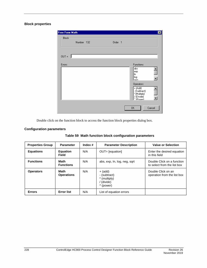
228 ControlEdge HC900 Process Control Designer Function Block Reference Guide Revision 26 November 2019
Block properties
Double click on the function block to access the function block properties dialog box.
Configuration parameters
Table 59 Math function block configuration parameters
Properties Group Parameter Index # Parameter Description Value or Selection
Equations Equation Field
N/A OUT= [equation] Enter the desired equation in this field
Functions Math Functions
N/A abs, exp, In, log, neg, sqrt Double Click on a function to select from the list box
Operators Math Operations
N/A + (add) - (subtract) * (multiply) / (divide) ^ (power)
Double Click on an operation from the list box
Errors Error list N/A List of equation errors

Revision 26 ControlEdge HC900 Process Control Designer Function Block Reference Guide 229 November 2019
Example Figure 52 shows a Function Block Diagram using a MATH function block to determine a general-purpose calculation output.
Figure 52 MATH function block example

230 ControlEdge HC900 Process Control Designer Function Block Reference Guide Revision 26 November 2019
Multiple Alarm with Hysteresis
Description The MALM label stands for the Multiple Alarm with Hysteresis. This block is part of the Alarm/Monitor category. It looks like this graphically.

Revision 26 ControlEdge HC900 Process Control Designer Function Block Reference Guide 231 November 2019
Function This block monitors five analog input values (SP1, SP2, SP3, SP4, SP5) and performs up to five alarm comparisons against the PV input. Alarm actions may be high, low or high deviation, low deviation or band deviation, In band deviation. For deviation alarming, a second analog signal provides the reference and set points represent deviation from the reference.
The associated output pins, ALARM1 through ALARM5, will turn ON if the configured alarm condition is present. The individual hysteresis settings for each alarm are used to prevent output cycling.
A user-specified hysteresis value in the engineering units of the process variable is provided.
An on-delay time value 0 to 99999.9 seconds is available to prevent momentary alarm actions. A digital Disable input is available to disable alarm actions.
The alarm output may be inverted to create normally active digital output. A user selection for latching until acknowledged reset is provided.
No Alarm pin is provided to indicate alarm state of this block. ON state indicates there is no alarm activated.
COUT pin is provided in the bottom to cascade high alarm code from the MALM block.
Alarm Type Function (PV>SP) - High Process Variable/Setpoint
ALARMx - ON If the PV is greater than the Setpoint*
ALARMx - OFF If the PV is less than the Setpoint* minus Hysteresis
(PV>CV) High Process Variable/Compare Value
ALARMx - ON If the PV is greater than the Compare Value (CV) i.e. Alarm Setpoint
ALARMx - OFF If the PV is less than the Compare Value minus Hysteresis
(PV<SP) Low Process Variable/Setpoint*
ALARMx - ON If the PV is less than the Setpoint*
ALARMx - OFF If the PV is greater than the Setpoint* + Hysteresis
(PV<CV) Low Process Variable/Compare Value
ALARMx - ON If the PV is less than the Compare Value (CV)
ALARMx - OFF If the PV is greater than the Compare Value + Hysteresis
[(PV-CV)>SP] High Deviation Alarm
ALARMx - ON If the PV input minus the CV input is greater than the Setpoint*
ALARMx - OFF If the PV input minus the CV input is less than the Setpoint* minus Hysteresis
[(CV-PV)>SP] Low Deviation Alarm
ALARMx - ON If the CV input minus the PV input is greater than the Setpoint*
ALARMx - OFF If the CV input minus the PV input is less than the Setpoint* minus Hysteresis
[(PV-CV)>SP] Band Deviation Alarm
ALARMx = ON If the absolute value of (PV-CV) is greater than the Setpoint*
ALARMx = OFF If the absolute value of (PV -V) is less than the Setpoint* minus Hysteresis
[(PV-CV)<SP] In Band Deviation Alarm
ALARMx = ON If the absolute value of (PV-CV) is less than the Setpoint*
ALARMx = OFF If the absolute value of (PV-CV) is greater than the Setpoint* plus Hysteresis
Where x = 1 to 5
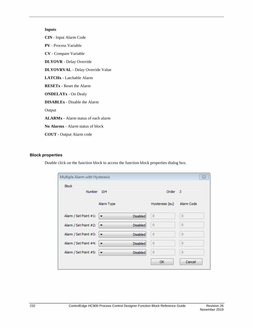
232 ControlEdge HC900 Process Control Designer Function Block Reference Guide Revision 26 November 2019
Inputs
CIN - Input Alarm Code
PV - Process Variable
CV - Compare Variable
DLYOVR - Delay Override
DLYOVRVAL - Delay Override Value
LATCHx - Latchable Alarm
RESETx - Reset the Alarm
ONDELAYx - On Dealy
DISABLEx - Disable the Alarm
Output
ALARMx - Alarm status of each alarm
No Alarmx - Alarm status of block
COUT - Output Alarm code
Block properties
Double click on the function block to access the function block properties dialog box.

Revision 26 ControlEdge HC900 Process Control Designer Function Block Reference Guide 233 November 2019
Configuration parameters
Table 60 MALM function block configuration parameters
Parameter Index # Parameter Description Value or Selection
Block Order N/A Execution Order for Block Read Only. To change block order, right-click on a Function Block and select Execution Order.
Tag Name N/A 16-character tag name (ASCII characters only)
Descriptor N/A Block description
Alarm Type N/A Alarm type PV>SP = High Process Variable/Local Setpoint
PV>CV = High Process Variable /Compare Value
PV<SP = Low Process Variable/Local Setpoint
PV<CV = Low Process Variable /Compare Value
(PV-CV)>SP = High Deviation Alarm
(CV-PV)>SP= Low Deviation Alarm
|PV-CV|>SP = Band Absolute Deviation Alarm
|PV-CV|<SP = In Band Absolute Deviation Alarm
Disabled
Hysteresis
5-9 Adjustable overlap of the on/off state of the Alarm output
0 to the span of the input in engineering units. It is positive value.
Alarm Code
10-14 Alarm code for each alarm to indicate priority of. High number indicates highest priority among all
It is in the range of 0-1000
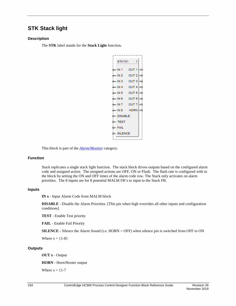
234 ControlEdge HC900 Process Control Designer Function Block Reference Guide Revision 26 November 2019
STK Stack light
Description The STK label stands for the Stack Light function.
This block is part of the Alarm/Monitor category.
Function
Stack replicates a single stack light function. The stack block drives outputs based on the configured alarm code and assigned action. The assigned actions are OFF, ON or Flash. The flash rate is configured with in the block by setting the ON and OFF times of the alarm code row. The Stack only activates on alarm priorities. The 8 Inputs are for 8 potential MALM FB’s to input to the Stack FB.
Inputs IN x - Input Alarm Code from MALM block
DISABLE - Disable the Alarm Priorities. [This pin when high overrides all other inputs and configuration conditions]
TEST - Enable Test priority
FAIL - Enable Fail Priority
SILENCE - Silence the Alarm Sound (i.e. HORN = OFF) when silence pin is switched from OFF to ON
Where x = 1-8
Outputs OUT x - Output
HORN - Horn/Hooter output
Where x = 1-7

Revision 26 ControlEdge HC900 Process Control Designer Function Block Reference Guide 235 November 2019
Block properties Double click on the function block to access the function block properties dialog box.
Configurable Parameters
Parameter Index # Parameter Description Value or Selection
Block Order Execution Order for Block Read Only. To change block order, right-click on a Function Block and select Execution Order.
Tag Name N/A 16-character tag name (ASCII characters only)
Descriptor N/A Block description
Alarm Code Low
0-5 Lower limit for alarm code range It is in the range of 1-1000
Alarm code 0 is used for priority 1.
Alarm Code High
6-11 Upper limit for alarm code range It is in the range of 1-1000
Alarm code 0 is used for priority 1.
ON time 12-21 On time for flashing It is in the range of 0-99999.9
OFF Time 22-31 Off Time for flashing It is in the range of 0-99999.9

236 ControlEdge HC900 Process Control Designer Function Block Reference Guide Revision 26 November 2019
MBR Modbus Read Function Block
Description The MBR label stands for Modbus Read. This block is part of the Communications category. It looks like this graphically.
Function A communication function block that expands the read capability of the Modbus Slave function block to 16 additional data points. Multiple blocks may be connected to the same Modbus Slave block.
The Modbus read block has no inputs and 16 outputs. Up to 16 registers can be configured as the source of data for the outputs.
The configuration data for each point will consist of:
• the address of the source device on the Modbus link,
• the register address of the desired data,
• and the register type: Integer, Float, or Bit Packed.
The sixteen outputs can be connected or tagged in the same manner as any other function block output.
Inputs ADDR = Slave address from associated MBS block. (Must be connected to a MBS block)
Outputs RD1 through RD16 – Last read value from selected address
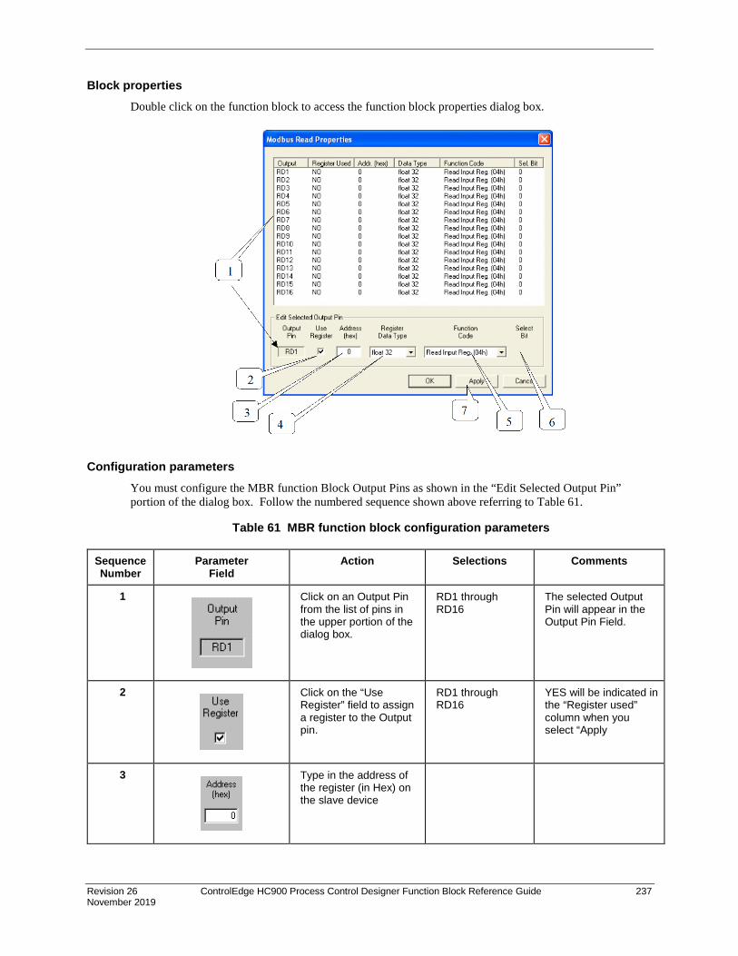
Revision 26 ControlEdge HC900 Process Control Designer Function Block Reference Guide 237 November 2019
Block properties Double click on the function block to access the function block properties dialog box.
Configuration parameters You must configure the MBR function Block Output Pins as shown in the “Edit Selected Output Pin” portion of the dialog box. Follow the numbered sequence shown above referring to Table 61.
Table 61 MBR function block configuration parameters
Sequence Number
Parameter Field
Action Selections Comments
1
Click on an Output Pin from the list of pins in the upper portion of the dialog box.
RD1 through RD16
The selected Output Pin will appear in the Output Pin Field.
2
Click on the “Use Register” field to assign a register to the Output pin.
RD1 through RD16
YES will be indicated in the “Register used” column when you select “Apply
3
Type in the address of the register (in Hex) on the slave device

238 ControlEdge HC900 Process Control Designer Function Block Reference Guide Revision 26 November 2019
Sequence Number
Parameter Field
Action Selections Comments
4
From the drop down menu, select the Register Data Type
• Float • Unsigned 32 • Signed 32 • Unsigned 16 • Signed 16 • Bit Packed • Single Bit
If read as an integer, the output is converted to a floating point.
5
Select a function code for “Float, Unsigned, Signed, or Bit Packed” register data type
• Read Holding Reg – Function Code 03
• Read Input Registers – Function Code 04
Function code 03 or Function code 04 is used to read the contents of input registers in the slave.
Select a function code for “Single Bit” Register data type.
• Read Coil Status – Function Code 01
• Read Input Status – Function Code 02
Function code 01 is used to read a slave's coil's (discrete output's) ON/OFF status of the slave device in a binary data format.
Function code 02 is used to read a slave's input's (discrete input's) ON/OFF status of the slave device in a binary data format.
Output is floating point equivalent (0.0 or 1.0).
NOTE: Refer to the Communications manual for the function codes supported by the specific device.
6
Select which bit (0-15) to read when Register Data Type = Bit Packed
0 to 15 If read as a bit packed number, you must select which bit to mask (0-15).
The output will be the floating-point equivalent (0.0 or 1.0) of the masked bit.
7 You must press [APPLY] to accept the register changes.

Revision 26 ControlEdge HC900 Process Control Designer Function Block Reference Guide 239 November 2019
Example Figure 53 shows a Function Block Diagram using Modbus function blocks.
Figure 53 MBR function block example

240 ControlEdge HC900 Process Control Designer Function Block Reference Guide Revision 26 November 2019
MBS Modbus Slave Function Block
Description The MBS label stands for Modbus Slave Status. This block is part of the Communications category. It looks like this.
Function A communication function block that is internally assigned to the configured S1 or S2 serial port that allows the controller to act as a master device and communicate with slave devices using the Modbus RTU protocol. Requires one block per slave device, up to 32 devices maximum. Only one block may be assigned to each slave device. It supports 4 read and 4 write parameters plus provides digital indication of communication integrity.
Inputs ENABLE = [ON] Slave device is in scan - If the Enable pin IS connected, then enabling/disabling follows the state of the Enable pin of the block and the enable/disable function on the diagnostic page of the HC Designer is grayed out. If the Enable pin is NOT connected, then the user must be in Monitor mode, Monitoring Serial Modbus Diagnostics in the HC Designer, select the device to be enabled or disabled, and click the Enable (or Disable) button.
EN1 through EN4 = [ON] Data value written once per scan
WR1 through WR4 = Values to be written to the selected register
ATTENTION
• This block does not support bit packing writing.
• If the register is an integer data type, the floating point input will be rounded up prior to writing to the address register.
• Message broadcasting is not supported on the HC900.
• MBS expects field device to be online & ready for communications on power-up. If devices starting at the same time, it is common to insert time-delay main “Enable” pin on Start or Restart from ASYS. After ~ 10-Bad Attempts, “NO SCAN” pin goes high. Delay between each future interrogation incrementally increases with each check.

Revision 26 ControlEdge HC900 Process Control Designer Function Block Reference Guide 241 November 2019
Outputs RD1 through RD4 = Last read value from the selected address
NO_SCAN = Scan Indication ON = Device is “Out of Scan” OFF = Device is “In Scan”.
BAD_COM = Communications Indication ON = Bad quality or device not defined OFF = Good Communications
ADDR = Slave Address for use with MBR and MBW function blocks
ATTENTION
• Integer values are converted to floating point values prior to output.
• If a Modbus slave device does not respond to a request, the last output value will be maintained.
Block properties Double click on the function block to access the function block properties dialog box.
Configuration parameters The ON/OFF properties dialog box is divided into Three tab cards:
GENERAL READ WRITE
Click on the tab to access the properties for that tab.
GENERAL tab
It looks like this graphically.

242 ControlEdge HC900 Process Control Designer Function Block Reference Guide Revision 26 November 2019
Table 62 describes the parameters and the value or selection.

Revision 26 ControlEdge HC900 Process Control Designer Function Block Reference Guide 243 November 2019
Table 62 MBS Block General tab configuration parameters
Properties Function Parameter Index # Parameter Description Value or Selection
Configure Modbus Slave
Slave Tag Name
N/A Description of Slave Device
16-character tag name (ASCII characters only)
Slave address and Tag Name must be unique within a control file.
Modbus Address
N/A Address of Slave device on the Modbus link
Enter unique address between 1 and 247
Default MB address = 255 which means slave will NOT be in scan
Modbus Double Register Format
Each IEEE 32-bit floating point number requires two consecutive registers (four bytes) starting with the register defined as the starting register for the information. The stuffing order of the bytes into the two registers differs among Modbus hosts. The selections are:
Selection Description Byte order
FP B Floating Point Big Endian Format 4, 3, 2, 1
FP BB Floating Point Big Endian with byte-swapped
3, 4, 1, 2
FP L Floating Point Little Endian Format 1, 2, 3, 4
FP LB Floating Point Little Endian with byte-swapped
2, 1, 4, 3
READ tab
It looks like this graphically.

244 ControlEdge HC900 Process Control Designer Function Block Reference Guide Revision 26 November 2019
Table 63 describes the parameters and the value or selection.

Revision 26 ControlEdge HC900 Process Control Designer Function Block Reference Guide 245 November 2019
Table 63 MBS Block Read tab configuration parameters
Properties Function Parameter Index # Parameter Description Value or Selection
Edit Output Pins Output Pin N/A Output pin designation Register request assigned to RD1, RD2, RD3, or RD4 pin
Use Register N/A Register Request Click on the “Use Register” field to assign a register to the Output pin.
Address (hex)
N/A Register Address Type in the address of the Read register (in Hex) on the slave device NOTE: A single configuration may contain up to 256 enabled registers.
Register Data Type
N/A Register data type From the drop down menu, select the Register Data Type
• Float
• Unsigned 32
• Signed 32
• Unsigned 16
• Signed 16
• Bit Packed
• Single Bit
If read as an integer, output is converted to floating point equivalent.

246 ControlEdge HC900 Process Control Designer Function Block Reference Guide Revision 26 November 2019
Properties Function Parameter Index # Parameter Description Value or Selection
Function Code
N/A Several standard Modbus RTU function codes are supported. These standard function codes provide basic support for IEEE 32-bit floating point numbers and 16-bit integer register representation of instrument’s process data
Function code 03 – Read Holding Registers or Function code 04 – Read Input Registers is used to read the contents of input registers in the slave.
Supported Data Types for Function Codes 03 and 04. From the drop down menu, select a function code for “Float, Unsigned, Signed, or Bit Packed” register data type
Function code 01 – Read Coil Status is used to read the coil’s (discrete output’s) ON/OFF status of the slave device in a binary data format.
Function code 02 – Read Input Status is used to read the input’s (discrete input’s) ON/OFF status of the slave device in a binary data format.
Supported Data Types for Function Codes 01 and 02. Select a function code for “Single Bit” Register data type.
NOTE: Refer to the Communications manual for the function codes supported by the specific device.
Select Bit N/A Bit to read when Read register’s data type = Bit Packed
You must then select which bit to mask (0-15).
The output will be the floating-point equivalent (0.0 or 1.0) of the masked bit.
0-15
Write tab
It looks like this graphically. Table 64 describes the parameters and the value or selection.

Revision 26 ControlEdge HC900 Process Control Designer Function Block Reference Guide 247 November 2019
Table 64 MBS Block Write tab configuration parameters
Properties Function Parameter Index # Parameter Description Value or Selection
Edit Input Pins Input Pin N/A Input pin designation Register request assigned to WR1,WR2,WR3, or WR4 pin
Use Register N/A Register Request Click on the “Use Register” field to assign a register to the Input pin.
Address (hex)
N/A Register Address Type in the address of the Write register (in Hex) on the slave device
Register Data Type
N/A Register data type From the drop down menu, select the Register Data Type
• Float
• Unsigned 32
• Signed 32
• Unsigned 16
• Signed 16
• Single bit

248 ControlEdge HC900 Process Control Designer Function Block Reference Guide Revision 26 November 2019
Properties Function Parameter Index # Parameter Description Value or Selection
Function Code
N/A Several standard Modbus RTU function codes are supported. These standard function codes provide basic support for IEEE 32-bit floating point numbers and 16-bit integer register and single bit representation of instrument’s process data
Preset Single Registers – Function Code 06
Preset Multiple Registers – Function Code 10 hex
The function code for “Unsigned 16 or Signed 16,” register data type is 06 – Preset Single Registers* presets integer value into a single register..
The function code for “Float, Unsigned 32 or Signed 32,” register data type is 10 hex – Preset Multiple Registers* presets values into holding registers.
*automatically selected when you select “Register Data Type”
NOTE: Refer to the Communications manual for the function codes supported by the specific device.

Revision 26 ControlEdge HC900 Process Control Designer Function Block Reference Guide 249 November 2019
Example Figure 54 shows a Function Block Diagram using Modbus function blocks.
Figure 54 MBS function block example

250 ControlEdge HC900 Process Control Designer Function Block Reference Guide Revision 26 November 2019
MBW Modbus Write Function Block
Description The MBW label stands for Modbus Write. This block is part of the Communications category. It looks like this graphically.
Function A communication function block that expands the write capability of the Modbus Slave function block to 8 additional data points. Multiple blocks may be connected to the same Modbus Slave block.
The Modbus write block has 8 inputs and no outputs. The Modbus destination for each of the eight inputs can be configured. An enable pin lets the data value be written once per scan.
The configuration data for each point will consist of : the address of the destination device on the Modbus link, the register address of the desired data, and the register type: Integer or Float.
Inputs EN1 through EN8 = [ON] Data value is written once per scan
WR1 through WR8 = Value to be written to the selected register address.
ADDR = Slave address from associated MBS block. (Must be connected to MBS block)
Outputs None

Revision 26 ControlEdge HC900 Process Control Designer Function Block Reference Guide 251 November 2019
Block properties Double click on the function block to access the function block properties dialog box.
Configuration parameters You must configure the MBW function Block Input Pins as shown in the “Edit Selected Input Pin” portion of the dialog box. Follow the numbered sequence shown above referring to Table 65.
Table 65 MBW function block configuration parameters
Sequence Number
Parameter Field
Action Selections Comments
1
Click on an Input Pin from the list of pins in the upper portion of the dialog box.
The selected Input Pin will appear in the “Input Pin” Field.
WR1 through WR8
2
Click on the “Use Register” field to assign a register to the Input pin.
YES will be indicated in the “Register Used” column when you select “Apply” .
WR1 through WR8
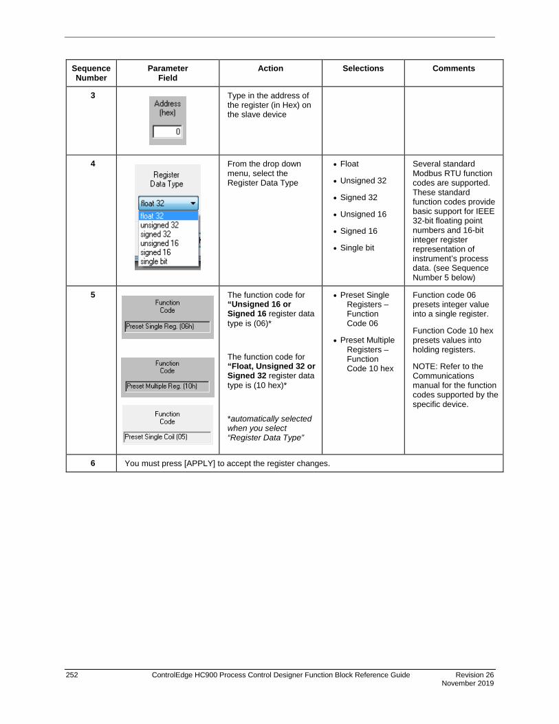
252 ControlEdge HC900 Process Control Designer Function Block Reference Guide Revision 26 November 2019
Sequence Number
Parameter Field
Action Selections Comments
3
Type in the address of the register (in Hex) on the slave device
4
From the drop down menu, select the Register Data Type
• Float
• Unsigned 32
• Signed 32
• Unsigned 16
• Signed 16
• Single bit
Several standard Modbus RTU function codes are supported. These standard function codes provide basic support for IEEE 32-bit floating point numbers and 16-bit integer register representation of instrument’s process data. (see Sequence Number 5 below)
5
The function code for “Unsigned 16 or Signed 16 register data type is (06)*
The function code for “Float, Unsigned 32 or Signed 32 register data type is (10 hex)*
*automatically selected when you select “Register Data Type”
• Preset Single Registers – Function Code 06
• Preset Multiple Registers – Function Code 10 hex
Function code 06 presets integer value into a single register.
Function Code 10 hex presets values into holding registers.
NOTE: Refer to the Communications manual for the function codes supported by the specific device.
6 You must press [APPLY] to accept the register changes.

Revision 26 ControlEdge HC900 Process Control Designer Function Block Reference Guide 253 November 2019
Example Figure 55 shows a Function Block Diagram using an Modbus function blocks.
Figure 55 MBW function block example

254 ControlEdge HC900 Process Control Designer Function Block Reference Guide Revision 26 November 2019
MDSW Mode Switch Function Block
Description The MDSW label stands for Mode Switch.
This block is part of the Loops category.
Function Digital interface to control loops to select automatic or manual modes and/or local or remote setpoint. Connects to PID, ON/OFF, CARB, or TPSC mode block input.
Inputs AUTO = Automatic Output mode (OFF to ON* sets MDRQO to Automatic control mode)
MAN = Manual Output mode (OFF to ON* sets MDRQO to Manual control mode)
LOCAL = Local Setpoint mode (OFF to ON* sets MDRQO to Local Setpoint mode)
REM = Remote Setpoint mode (OFF to ON* sets MDRQO to Remote Setpoint mode)
* for one control cycle
Output MDRQO (Mode Request Output) = The output of this block must connect to the MDRQI input of a PID, CARB, TPSC, or ON/OFF function block.
Block properties Double click on the function block to access the function block properties dialog box.

Revision 26 ControlEdge HC900 Process Control Designer Function Block Reference Guide 255 November 2019
Example Figure 56 shows a Function Block Diagram using an MDSW function block.
Application: External mode switching of the PID Block - changing a loop to MAN, to AUTO, to LOCAL SP, or REMOTE SP.
ATTENTION
Mode switching is also provided as an integral part of the Operator Panel, Loop Displays.
The MDSW (Mode Switch) Function Block is used exclusively with the MDRQI (Mode Request Input) of the PID, ON/OFF, CARB< or TPSC Function Block. Its output provides encoded switch commands to the PID Block.
All inputs are OFF to ON edge-triggered, requiring a separate input for each action. The example shows digital inputs as the transfer inputs but any digital status could be used.
Figure 56 MDSW function block example

256 ControlEdge HC900 Process Control Designer Function Block Reference Guide Revision 26 November 2019
MDFL Mode Flag Function Block
Description The MDFL label stands for Mode Flag.
This block is part of the Loops category.
Function Turns ON the output that corresponds to the current value of MODE.
Turns OFF all other outputs.
Input MODE = The MODE input must connect to the MODE output of a PID, CARB, TPSC, or ONOFF function block.
Output REM = ON If MODE = Remote Setpoint
LOCAL = ON If MODE = Local Setpoint
AUTO = ON If MODE = Automatic Control
MAN = ON If MODE = Manual Control
IMAN = ON If MODE = Loop in Initialization Manual
LO = ON If MODE = Local Override
Block properties Double click on the function block to access the function block properties dialog box.

Revision 26 ControlEdge HC900 Process Control Designer Function Block Reference Guide 257 November 2019
Example Figure 57 shows a Function Block Diagram using an MDFL function block. The mode output of the PID Block is used exclusively with the MDFL (Mode Flags) Block.
Any of the status outputs may be referenced by a Signal Tag or may be transferred externally using a DO.
The output shown is ON when in Manual and OFF when in Automatic.
Figure 57 MDFL function block example
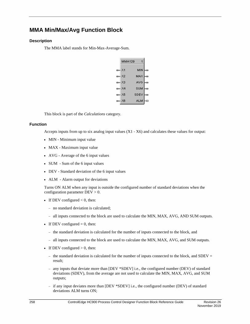
258 ControlEdge HC900 Process Control Designer Function Block Reference Guide Revision 26 November 2019
MMA Min/Max/Avg Function Block
Description The MMA label stands for Min-Max-Average-Sum.
This block is part of the Calculations category.
Function Accepts inputs from up to six analog input values (X1 - X6) and calculates these values for output:
• MIN - Minimum input value
• MAX - Maximum input value
• AVG - Average of the 6 input values
• SUM - Sum of the 6 input values
• DEV - Standard deviation of the 6 input values
• ALM - Alarm output for deviations
Turns ON ALM when any input is outside the configured number of standard deviations when the configuration parameter DEV > 0.
• If DEV configured < 0, then:
− no standard deviation is calculated;
− all inputs connected to the block are used to calculate the MIN, MAX, AVG, AND SUM outputs.
• If DEV configured = 0, then:
− the standard deviation is calculated for the number of inputs connected to the block, and
− all inputs connected to the block are used to calculate the MIN, MAX, AVG, and SUM outputs.
• If DEV configured > 0, then:
− the standard deviation is calculated for the number of inputs connected to the block, and SDEV = result;
− any inputs that deviate more than [DEV *SDEV] i.e., the configured number (DEV) of standard deviations (SDEV), from the average are not used to calculate the MIN, MAX, AVG, and SUM outputs;
− if any input deviates more than [DEV *SDEV] i.e., the configured number (DEV) of standard deviations ALM turns ON;

Revision 26 ControlEdge HC900 Process Control Designer Function Block Reference Guide 259 November 2019
− if all inputs deviate more than [DEV *SDEV] i.e., the configured number (DEV) of standard deviations(SDEV), then the MIN, MAX, AVG, and SUM outputs all equal zero (0), and ALM turns ON.
• Standard Deviation (SDEV) =
where: X = AVG n = the number of connected inputs.
Input X1 = First analog value.
X2 = Second analog value.
X3 = Third analog value.
X4 = Fourth analog value.
X5 = Fifth analog value.
X6 = Sixth analog value.
Output MIN = Calculated minimum analog value.
MAX = Calculated maximum analog value.
AVG = Calculated average of analog values.
SU = Calculated sum of analog values.
SDEV = Square root of Z divided by N, where Z = the sum of individual squared deviations from the average of the first n inputs.
ALM = Digital signal for alarm indication.
Block properties
Double click on the function block to access the function block properties dialog box.
i = n∑
i = 1n
(X - X)2i

260 ControlEdge HC900 Process Control Designer Function Block Reference Guide Revision 26 November 2019
Configuration parameters
Table 66 Min/Max/Ave/Sum function block configuration parameters
Properties Group Parameter Index # Parameter Description Value or Selection
Set Calculation Parameters
Inputs Used N/A Number of inputs connected to block
(Connect inputs in numerical order; that is, unused inputs from the bottom up - X6, X5, etc.)
Unused inputs default to 0.
1 to 6
Standard Deviations
1 Number of standard deviations within which inputs are used for calculation
–99999 to 99999
<0 No Standard Deviation
=0 Standard Deviation with no alarm
>0 Standard Deviation with alarm
Example Figure 58 shows a Function Block Diagram using an MMA function block. In this application, control is determined by automatic selection of the lowest or highest sensor, such as a thermocouple. As shown the MMA block is configured for highest (MAX).
Figure 58 MMA function block example

Revision 26 ControlEdge HC900 Process Control Designer Function Block Reference Guide 261 November 2019
8MMA – Similar to the original MMA with auto-pruning of input channel used in the calculation.
Description
The 8MMA label stands for Eight Min-Max-Average-Sum. This block is part of the Calculations category.
Function
Accepts inputs from up to eight analog input values (X1 – X8) with individual disables and calculates these values for output:
MINimum input value
MAXimum input value
AVeraGe of input values
SUM of input values
Standard DEViation value
ALarM output for deviations
Turns ON ALM when any input is outside the configured number of standard deviations when the configuration parameter DEV > 0.

262 ControlEdge HC900 Process Control Designer Function Block Reference Guide Revision 26 November 2019
If DEV configured < 0, then:
– no standard deviation is calculated;
– all inputs connected to the block are used to calculate the MIN, MAX, AVG, AND SUM outputs
If DEV configured = 0, then:
– the standard deviation is calculated for the number of inputs connected to the block, but
– all inputs connected to the block are used to calculate the MIN, MAX, AVG, and SUM outputs.
If DEV configured > 0, then:
– the standard deviation is calculated for the number of inputs connected to the block, and SDEV = result;
– any inputs that deviate more than [DEV * SDEV] i.e. the configured number (DEV) of standard deviations(SDEV), from the average are not used to calculate the MIN, MAX, AVG, and SUM outputs.
– if any input deviates more than [DEV * SDEV] i.e. the configured number (DEV) of standard deviations (SDEV), ALM turns ON.
– if all inputs deviate more than [DEV * SDEV] i.e. the configured number (DEV) of standard deviations(SDEV), then the MIN, MAX, AVG, and SUM outputs all equal zero (0), and ALM turns ON.
Input
X1 = First analog value.
X2 = Second analog value.
X3 = Third analog value.
X4 = Fourth analog value.
X5 = Fifth analog value.
X6 = Sixth analog value.
X7 = Seventh analog value.
X8 = Eight analog value.
Dis X1 = Disable X1 Input.
Dis X2 = Disable X2 Input.
Dis X3 = Disable X3 Input.
Dis X4 = Disable X4 Input.
Dis X5 = Disable X5 Input.
Dis X6 = Disable X6 Input.
Dis X7 = Disable X7 Input.
Dis X8 = Disable X8 Input.

Revision 26 ControlEdge HC900 Process Control Designer Function Block Reference Guide 263 November 2019
Output
MIN = Calculated minimum enabled analog value.
MAX = Calculated maximum enabled analog value.
AVG = Calculated average of enabled analog values.
SU = Calculated sum of enabled analog values.
SDEV = Square root of Z divided by N, where Z = the sum of individual squared deviations from
the average of the first n inputs.
ALM = Digital signal for alarm indication.
Configurable Parameters
Parameter Index# Description Value or Selection
Standard Deviations
1 Number of standard deviations within which inputs are used for calculation
–99999 to 99999
<0 No Standard Deviation
=0 Standard Deviation with no alarm
>0 Standard Deviation with alarm

264 ControlEdge HC900 Process Control Designer Function Block Reference Guide Revision 26 November 2019
MSF Mass Flow Calculation Function Block
Description The MSF label stands for Mass Flow Calculation.
This block is part of the Calculations category.
Function Calculates gas mass flow (OUT) from differential pressure input value (X) that represents a pressure drop across an orifice plate (for example). It accepts two other inputs to include pressure (Y) and/or temperature (Z) compensation in the calculation. The calculation includes square root extraction.
• OUT = Kq * sqrt [(dP * P) / T]
Kq = Orifice Constant
dP = Differential pressure which
= (Kx * X) + Bx; where:
Kx = Delta pressure scaled for desired engineering units X = Analog input value Bx = Delta pressure bias in desired engineering units
P = Absolute gas pressure which
= (Ky * Y) + By; where:
Ky = Pressure scaler for desired engineering units Y = Gas pressure analog input value By = Pressure bias in desired engineering units
T = Absolute gas temperature which
= (Kz * Z) + Bz; where:
Kz = Temperature scaler for desired engineering units Z = Gas temperature analog input value Bz = Temperature bias in desired engineering units
If (Kz* Z) + Bz = 0, then: OUT = 0
• If calculation is <= Dropoff, OUT = 0, else OUT = Calculation

Revision 26 ControlEdge HC900 Process Control Designer Function Block Reference Guide 265 November 2019
Input X = Differential pressure analog value. Y = Gas pressure analog value. Z = Gas Temperature analog value.
Output OUT = Calculated analog value
Block properties
Double click on the function block to access the function block properties dialog box.
Configuration parameters
Table 67 Mass flow function block configuration parameters
Properties Group Parameter Index # Parameter Description Value or Selection
Set Calculation Parameters
Kq 0 Orifice constant –99999 to 999999
Kx 1 Delta pressure scaler –99999 to 999999
Ky 2 Pressure scaler –99999 to 999999
Kz 3 Temperature scaler –99999 to 999999
By 4 Pressure bias –99999 to 999999(EU)
Bx 5 Delta pressure bias –99999 to 999999(EU)
Bz 6 Temperature bias –99999 to 999999(EU)
Low Cutoff 7 Low Dropoff Value sets the output to zero when the calculation is below this limit.
0 to 99999 in Engineering Units

266 ControlEdge HC900 Process Control Designer Function Block Reference Guide Revision 26 November 2019
Example Figure 59 shows a MSF Function Block Diagram using inputs to calculate a mass flow output.
Figure 59 MSF function block example

Revision 26 ControlEdge HC900 Process Control Designer Function Block Reference Guide 267 November 2019
MUL Multiplier Function Block
Description The MUL label stands for Multiplication Mathematical operation (2 Inputs).
This block is part of the Math category..
Function Multiplies one analog input value (X) by another (Y).
• OUT = X * Y
Input X = First analog value
Y = Second analog value
Output OUT = Calculated analog value
Block properties Double click on the function block to access the function block properties dialog box.

268 ControlEdge HC900 Process Control Designer Function Block Reference Guide Revision 26 November 2019
Example Figure 60 shows a Function Block Diagram using a MUL function block
Figure 60 MUL function block example

Revision 26 ControlEdge HC900 Process Control Designer Function Block Reference Guide 269 November 2019
4MUL Multiplier (4 input) Function Block
Description The 4MUL label stands for Multiplication Mathematical Operation (4Inputs).
This block is part of the Math category.
Function Multiplies four inputs to get an output.
Input X1 = First analog value X2 = Second analog value X3 = Third Analog value Y = Fourth Analog value
ATTENTION
All four inputs must be connected. Unconnected inputs default to zero. If only three inputs are needed, the fourth should be connected to a constant value of 1.
Output OUT = Calculated analog value
Block properties Double click on the function block to access the function block properties dialog box.
Example Figure 61 shows correct and incorrect example of a 4MUL function block. Note that all unused inputs must be connected to a constant value of one.

270 ControlEdge HC900 Process Control Designer Function Block Reference Guide Revision 26 November 2019
Figure 61 4MUL function block example

Revision 26 ControlEdge HC900 Process Control Designer Function Block Reference Guide 271 November 2019
NEG Negate Function Block
Description The NEG label stands for Negate.
This block is part of the Calculations category.
Function Convert a value to the opposite sign; i.e., +5 IN = –5 OUT, –6 IN = +6 OUT. (Invert sign of an analog value.)
Input X = positive or negative analog value
Output Y = analog value of opposite sign from input
Block properties Double click on the function block to access the function block properties dialog box.
Example Figure 62 shows a Function Block Diagram using a NEG function block.
Figure 62 NEG function block example

272 ControlEdge HC900 Process Control Designer Function Block Reference Guide Revision 26 November 2019
NOT Function Block
Description The NOT label stands for the NOT Boolean logic function or Logic Inverter.
This block is part of the Logic and Fast Logic categories..
Function Reverse state of a digital input (X).
• OUT = Opposite state of X If X = ON, then: OUT = OFF. IF X = OFF, then: OUT = ON.
Input X = Digital signal
Output OUT = Complement of input signal
Block properties Double click on the function block to access the function block properties dialog box.
Example Figure 63 shows a Function Block Diagram using a NOT function block. Use a single input to place a loop in manual when the input is ON (1) and return to Auto when OFF (0).
Figure 63 NOT function block example
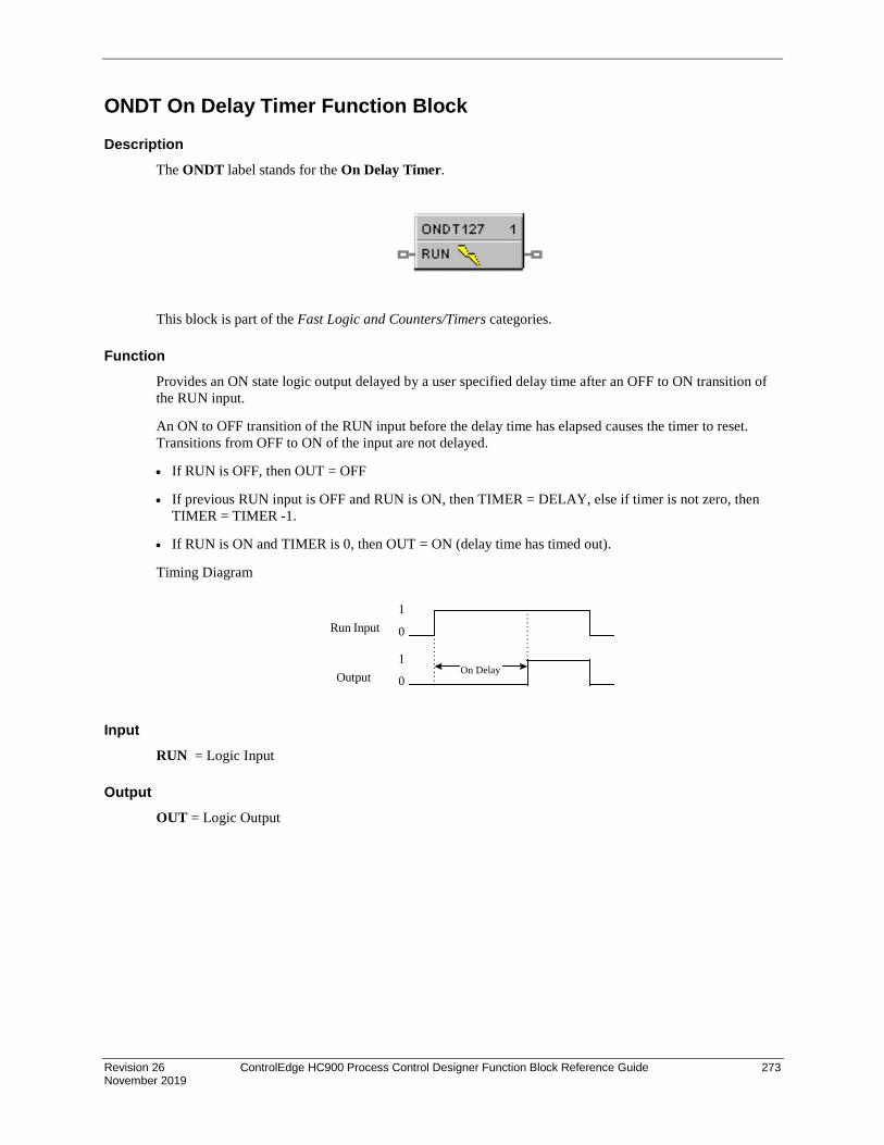
Revision 26 ControlEdge HC900 Process Control Designer Function Block Reference Guide 273 November 2019
ONDT On Delay Timer Function Block
Description The ONDT label stands for the On Delay Timer.
This block is part of the Fast Logic and Counters/Timers categories.
Function Provides an ON state logic output delayed by a user specified delay time after an OFF to ON transition of the RUN input.
An ON to OFF transition of the RUN input before the delay time has elapsed causes the timer to reset. Transitions from OFF to ON of the input are not delayed.
• If RUN is OFF, then OUT = OFF
• If previous RUN input is OFF and RUN is ON, then TIMER = DELAY, else if timer is not zero, then TIMER = TIMER -1.
• If RUN is ON and TIMER is 0, then OUT = ON (delay time has timed out).
Timing Diagram
Input RUN = Logic Input
Output OUT = Logic Output
On Delay
1
0
1
0
Run Input
Output

274 ControlEdge HC900 Process Control Designer Function Block Reference Guide Revision 26 November 2019
Block properties
Double click on the function block to access the function block properties dialog box.
Configuration parameters
Table 68 On delay timer function block example
Properties Group Parameter Index # Parameter Description Value or Selection
Time Delay Time delay 0 Delay Time - specifies the amount of time the ON state logic output will occur after an OFF to ON transition of the RUN input.
0.1 sec, 0 to 99999.9
Enter as 0.1 to 99999 in 0.1 increments

Revision 26 ControlEdge HC900 Process Control Designer Function Block Reference Guide 275 November 2019
Example Figure 64 shows a Function Block Diagram using an ONDT function block.
Figure 64 ONDT function block example

276 ControlEdge HC900 Process Control Designer Function Block Reference Guide Revision 26 November 2019
OFDT Off Delay Timer Function Block
Description The OFDT label stands for the Off Delay Timer.
This block is part of the Fast Logic and Counters/Timers categories.
Function Provides an OFF state logic output delayed by a user specified delay time after an On to OFF transition of the RESET input.
An OFF to ON transition of the RESET input before the delay time has elapsed causes the timer to reset. Transitions from OFF to ON of the input are not delayed.
• IF RESET is ON, then OUT = ON.
• If previous RESET input is ON and RESET is OFF, then TIMER = DELAY.
• If RESET is OFF and TIMER is not 0, then time = TIMER – 1.
• If RESET is OFF and TIMER is 0, then OUT = OFF (delay time is reset).
Timing Diagram
Input RST = Logic Input
Output OUT = Logic Output
Off Delay
1
0
1
0
Rst Input
Output

Revision 26 ControlEdge HC900 Process Control Designer Function Block Reference Guide 277 November 2019
Block properties
Double click on the function block to access the function block properties dialog box.
Configuration parameters
Table 69 Off delay timer configuration parameters
Properties Group Parameter Index # Parameter Description Value or Selection
Time Delay Time delay 0 Delay Time - specifies the amount of time the OFF state logic output will occur after an ON to OFF transition of the Reset input.
0.1 sec, 0 to 99999.9
Enter as 0.1 to 99999 in 0.1 increments.
Example Figure 65 shows a Function Block Diagram using an OFDT function block.
An OFF delay timer block output is ON as long as the RST input islogic HI (ON). It can be used for time duration but must betriggered by an ON to OFF transition on the Reset input. This canbe accomplished using Trigger blocks to create one-shot pulseswhich last one scan cycle. The fast logic trigger pulse will last 100ms. while the normal logic trigger pulse will last the complete scancycle for analog blocks. Use according to application need. APeriodic timer output pulse may also be used to start the timer forthe OFF delay.
Off delay
AND4 output
TRIG1 output
OFDT2 output
Timing Diagram

278 ControlEdge HC900 Process Control Designer Function Block Reference Guide Revision 26 November 2019
Figure 65 OFDT function block example
ON/OFF Function Block
Description The ON/OFF label stands for the On/Off Control function.
This block is part of the Loops category.
Function Provide ON/OFF control. The output is either ON (100 %) or OFF (0 %).
Inputs RSP = Remote Setpoint (% or EU per SP Units)
TRV = Track Value Output—1 = ON, 0 = OFF
TRC = Track Value Command—1 = enable, 0 = disable (Mode = Local Override)
SWI = Switch Inputs (from LPSW function block)
MDRQI = External Mode Request (connected to the MDRQO output of a MDSW function block) encoded as follows:
0.0 = No Change 1.0 = Manual Mode Request 2.0 = Automatic Mode Request 4.0 = Local Setpoint Request 8.0 = Remote Setpoint Request

Revision 26 ControlEdge HC900 Process Control Designer Function Block Reference Guide 279 November 2019
Outputs WSP = Working Setpoint in Engineering Units for monitoring
AL1 = Alarm 1
AL2 = Alarm 2
DIRECT = ON = Direct; OFF = Reverse
MODE = Actual Mode encoded as follows: (Connect to Mode Flags block [MDFL] to encode mode status.)
0.0 RSP AUTO 1.0 RSP MAN 2.0 RSP Initialization Manual (See ATTENTION) 3.0 RSP Local Override (See ATTENTION) 4.0 LSP AUTO 5.0 LSP MAN 6.0 LSP Initialization Manual (See ATTENTION) 7.0 LSP Local Override (See ATTENTION)
BCO = Back Calculation Output (for blocks used as Cascade Secondary
ATTENTION
When a request to change from Auto to manual is received and:
• the request comes from the operator Interface, the request is ignored.
• the request comes from the Mode Switch (MDSW) function block, the request is retained and when leaving the Initialization Mode or Local Override Mode the loop will go to manual.
Block properties Double click on the function block to access the function block properties dialog box.
Configuration parameters The ON/OFF properties dialog box is divided into 5 tab cards:
GENERAL START/RESTART RSP RANGE/LIMIT ALARMS
Click on the tab to access the properties for that tab.

280 ControlEdge HC900 Process Control Designer Function Block Reference Guide Revision 26 November 2019
GENERAL tab
Table 70 ON/OFF General tab configuration parameters
Properties Function Parameter Index # Parameter Description Value or Selection Block Order N/A Execution Order Read Only. To change block
order, right-click on a Function Block and select Execution Order.
Tag Name N/A 16-character tag name (ASCII characters only)
Descriptor N/A Block description Control Direction N/A Control Action REVERSE - Proportional action
causes output to decrease as process variable increases. DIRECT - Proportional action causes output to increase as process variable increases.
SP Tracking N/A Setpoint Tracking NONE TRACK PV - When control mode is “manual”, local setpoint tracks process variable. TRACK RSP - When setpoint is remote setpoint, local setpoint tracks remote setpoint.
Hysteresis 19 Output Hysteresis 0 % to 10 % of input span

Revision 26 ControlEdge HC900 Process Control Designer Function Block Reference Guide 281 November 2019
START/RESTART tab

282 ControlEdge HC900 Process Control Designer Function Block Reference Guide Revision 26 November 2019
Table 71 ON/OFF Start/Restart tab configuration parameter
Modes and Setpoints
Permitted Mode
MAN 4
AUTO 5
Mode permitted for the initial start and power up mode.
Manual
Automatic
May select both, must select one.
Permitted Setpoint
LSP 6
RSP 7
Setpoint permitted for the initial start and power up mode.
Local Setpoint
Remote Setpoint
May select both, must select one.
Initial Mode N/A Mode at NEWSTART
Newstart is the first scan cycle following the cold start of the controller
Manual
Automatic
Select one
Setpoint for Initial Mode
N/A Setpoint at NEWSTART
Newstart is the first scan cycle following the cold start of the controller
Local Setpoint
Remote Setpoint
Select one
Power up Mode
N/A Mode at power up Manual
Retain Last Mode Same mode (auto or manual)
Select one
Power up Setpoint
N/A Setpoint at power up Local Setpoint
Retain Last LSP/RSP Same Setpoint (LSP or RSP)
Select one
Power Up Out
Power Up Out
N/A Output at Power up LAST OUT - Same as at power down.
FAILSAFE - Failsafe output value.
Failsafe Out 29 Failsafe Output Value –5 % to 105 %
Initial Setpoint Value
Use initial LSP
30 Use Initial Local Setpoint
Click on radio button to select.
Initial LSP Value
31 Initial Local Setpoint Value
Enter Initial Local Setpoint Value.

Revision 26 ControlEdge HC900 Process Control Designer Function Block Reference Guide 283 November 2019
RSP tab
Table 72 ON/OFF RSP tab configuration parameters
Properties Function
Parameter Index # Parameter Description Value or Selection
Remote Setpoint Source and Units
Use RSP Input (EU)
N/A Use Remote Setpoint in Engineering Units
Click on radio button to select
Use RSP Input (%)
Use Remote Setpoint in Percent
Click on radio button to select
Use LSP2 (EU)
Use Local Setpoint #2 in Engineering Units
Click on radio button to select
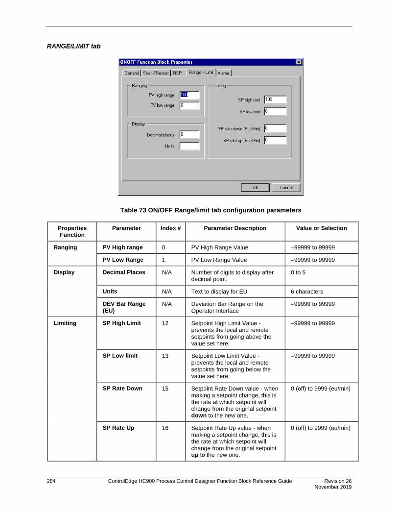
284 ControlEdge HC900 Process Control Designer Function Block Reference Guide Revision 26 November 2019
RANGE/LIMIT tab
Table 73 ON/OFF Range/limit tab configuration parameters
Properties Function
Parameter Index # Parameter Description Value or Selection
Ranging PV High range 0 PV High Range Value –99999 to 99999
PV Low Range 1 PV Low Range Value –99999 to 99999
Display Decimal Places N/A Number of digits to display after decimal point.
0 to 5
Units N/A Text to display for EU 6 characters
DEV Bar Range (EU)
N/A Deviation Bar Range on the Operator Interface
–99999 to 99999
Limiting SP High Limit 12 Setpoint High Limit Value - prevents the local and remote setpoints from going above the value set here.
–99999 to 99999
SP Low limit 13 Setpoint Low Limit Value - prevents the local and remote setpoints from going below the value set here.
–99999 to 99999
SP Rate Down 15 Setpoint Rate Down value - when making a setpoint change, this is the rate at which setpoint will change from the original setpoint down to the new one.
0 (off) to 9999 (eu/min)
SP Rate Up 16 Setpoint Rate Up value - when making a setpoint change, this is the rate at which setpoint will change from the original setpoint up to the new one.
0 (off) to 9999 (eu/min)

Revision 26 ControlEdge HC900 Process Control Designer Function Block Reference Guide 285 November 2019
ALARMS tab
Table 74 ON/OFF Alarm tab configuration parameters
Properties Function
Parameter Index # Parameter Description Value or Selection
Alarm 1 Setpoint 1 20 Alarm 1 Setpoint 1 Value - this is the value at which you want the alarm type chose below to activate
–99999 to 99999 in Engineering Units
Type N/A Alarm 1 Setpoint 1 Type - select what you want Alarm 1 Setpoint 1 to represent.
Selections: NO ALARM PV_HIGH PV_LOW DEV_HIGH DEV_LOW SP_HIGH SP_LOW OUT_HIGH OUT_LOW
Setpoint 2 21 Alarm 1 Setpoint 2 Value Same as Alarm 1 Setpoint 1
Type N/A Alarm 1 Setpoint 2 Type Same as Alarm 1 Setpoint 1
Alarm 2 Setpoint 1 22 Alarm 2 Setpoint 1 Value Same as Alarm 1 Setpoint 1
Type N/A Alarm 2 Setpoint 1 Type Same as Alarm 1 Setpoint 1
Setpoint 2 23 Alarm 2 Setpoint 2 Value Same as Alarm 1 Setpoint 1
Type N/A Alarm 2 Setpoint 2 Type Same as Alarm 1 Setpoint 1
Alarm Hysteresis % 28 Alarm Hysteresis in % 0 % to 5 %

286 ControlEdge HC900 Process Control Designer Function Block Reference Guide Revision 26 November 2019
Example Figure 66 shows a Function Block Diagram using an ON/OFF function block.
Figure 66 ON/OFF function block example
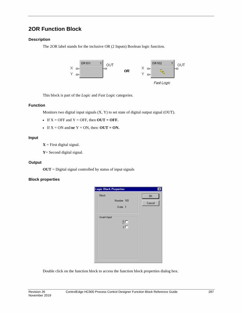
Revision 26 ControlEdge HC900 Process Control Designer Function Block Reference Guide 287 November 2019
2OR Function Block
Description The 2OR label stands for the inclusive OR (2 Inputs) Boolean logic function.
This block is part of the Logic and Fast Logic categories.
Function Monitors two digital input signals (X, Y) to set state of digital output signal (OUT).
• If X = OFF and Y = OFF, then OUT = OFF.
• If X = ON and/or Y = ON, then: OUT = ON.
Input X = First digital signal.
Y= Second digital signal.
Output OUT = Digital signal controlled by status of input signals
Block properties
Double click on the function block to access the function block properties dialog box.

288 ControlEdge HC900 Process Control Designer Function Block Reference Guide Revision 26 November 2019
Input state You can invert Input 1 or input 2 or both. If the input is inverted, an input line that is ON is seen as OFF. (“N” appears on Icon next to the inverted input.)
Example Figure 67 shows a Function Block Diagram using a 2OR function block.
Figure 67 2OR function block example
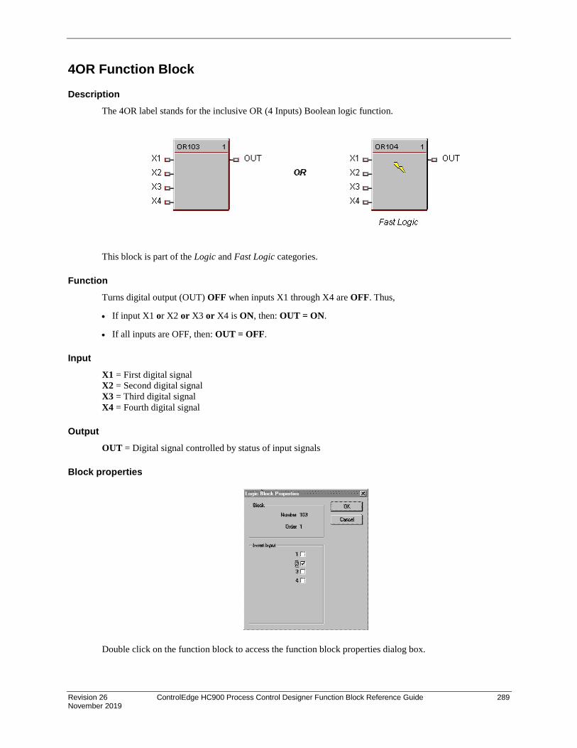
Revision 26 ControlEdge HC900 Process Control Designer Function Block Reference Guide 289 November 2019
4OR Function Block
Description The 4OR label stands for the inclusive OR (4 Inputs) Boolean logic function.
This block is part of the Logic and Fast Logic categories.
Function Turns digital output (OUT) OFF when inputs X1 through X4 are OFF. Thus,
• If input X1 or X2 or X3 or X4 is ON, then: OUT = ON.
• If all inputs are OFF, then: OUT = OFF.
Input X1 = First digital signal X2 = Second digital signal X3 = Third digital signal X4 = Fourth digital signal
Output OUT = Digital signal controlled by status of input signals
Block properties
Double click on the function block to access the function block properties dialog box.

290 ControlEdge HC900 Process Control Designer Function Block Reference Guide Revision 26 November 2019
Input state You can invert Input 1, 2, 3, 4, or all. If the input is inverted, an input line that is ON is seen as OFF. (“N” appears on the Icon next to the inverted input.)
ATTENTION
Unused Inputs default to 0.
Example Figure 68 shows a Function Block Diagram using a 4OR function block.
Output = X1 or X2 or X3 or X4
Figure 68 4OR function block example

Revision 26 ControlEdge HC900 Process Control Designer Function Block Reference Guide 291 November 2019
8OR Function Block
Description The 8OR label stands for the inclusive OR (8 Inputs) Boolean logic function.
This block is part of the Logic and Fast Logic categories.
Function Turns digital output (OUT) OFF when inputs X1 through X8 are off, thus:
• If input X1 or X2 or X3 or X4 or X5 or X6 or X7 or X8 is ON, then: OUT = ON.
• If all inputs are OFF, then: OUT = OFF.
Input X1 = First digital signal X2 = Second digital signal X3 = Third digital signal X4 = Fourth digital signal X5 = Fifth digital signal X6 = Sixth digital signal X7 = Seventh digital signal X8 = Eight digital signal.
Output OUT = Digital signal controlled by status of input signals
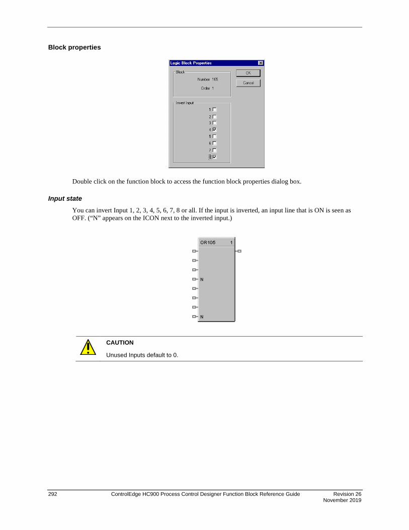
292 ControlEdge HC900 Process Control Designer Function Block Reference Guide Revision 26 November 2019
Block properties
Double click on the function block to access the function block properties dialog box.
Input state
You can invert Input 1, 2, 3, 4, 5, 6, 7, 8 or all. If the input is inverted, an input line that is ON is seen as OFF. (“N” appears on the ICON next to the inverted input.)
CAUTION
Unused Inputs default to 0.

Revision 26 ControlEdge HC900 Process Control Designer Function Block Reference Guide 293 November 2019
Example Figure 69 shows a Function Block Diagram using an 8OR function block.
Output = X1 or X2 or X3 or X4 or X5 or X6 or X7 or X8
Figure 69 8OR function block example

294 ControlEdge HC900 Process Control Designer Function Block Reference Guide Revision 26 November 2019
PB Pushbutton Function Block
Description The PB label stands for the inclusive Pushbutton.
This block is part of the Logic category.
Function Provides the interface from the operator panel to the logic functions of the controller. Provides a one-shot logic ON in response to pressing the corresponding function key on the operator interface.
This selection lets you configure the Pushbutton function display that will provide the interface to the four logic operator keypad keys (F1 through F4). You can do this for up to four Pushbutton blocks giving you 4 groups (total 16 pushbuttons) that can be set up for selection on your display buttons (1-8).
When you select a pushbutton group on a display button (1-8), the operator interface will display the pushbutton function group screen and buttons F1-F4 on the operator interface will display the information that has been set up for that group.
Output F1 = Provide 1 shot logic ON in response to pressing Pushbutton F1 F2 = Provide 1 shot logic ON in response to pressing Pushbutton F2 F3 = Provide 1 shot logic ON in response to pressing Pushbutton F3 F4 = Provide 1 shot logic ON in response to pressing Pushbutton F4
Configuration Double click on the function block to access the “Pushbutton Display Configuration” dialog box.

Revision 26 ControlEdge HC900 Process Control Designer Function Block Reference Guide 295 November 2019
Configuration procedure Follow the procedure in Table 75 to configure the Pushbutton Function Groups.
Table 75 Pushbutton function group configuration
• There are four pushbuttons that can be configured for each block.
You can assign just a label for the display using the Output descriptor.
You can also select signal tags from the “Signal Tag List” if you require a feedback signal to be shown on the pushbutton display.
• Enter the Tag Name Text in the appropriate field.
• Enter the Group Title Text in the appropriate field.
The “Signal Tag List” field shows all the Signal Tags that have been configured on the Function Block Diagram. Select “All Signals”, ”Analog Signals”, or “Digital Signals”.
• To Add a Digital Signal tag to a Pushbutton location: Click on a signal tag in the list, then click on “Insert/Replace”. The selected Signal tag will be placed in the next available position in the “Signal Tags/Descriptors” field.
• To Insert a Digital Signal tag to a Pushbutton location: Select a position in the “Signal Tags/Descriptors” field., then click on INSERT. (You must click in the first column of the Selected Signal Tag list to select a row.) The selected Signal tag will be placed in the position chosen, and other signal tags will move down as required. You may only insert to the occupied portion of the list. An attempt to insert to any empty row will place the new item in the first empty row.

296 ControlEdge HC900 Process Control Designer Function Block Reference Guide Revision 26 November 2019
The selected Signal Tag will be placed in the “Signal Tags/Descriptors” field
• Repeat selection for up to 4 Pushbuttons.
• To delete a selected Tag, click on the position of the tag and click “Delete”.
• To Add or Edit and output descriptor to the display, click on the “Bttn” number and then on “Edit Descriptor” and type in the descriptor in the Edit field.
• Click “OK”.
You can assign Pushbutton Configuration Groups to Display Buttons, refer to Display Buttons (1-8) Configuration in the Process Control Designer User's Guide.
Example Figure 70 is an overview of a pushbutton configuration.
Figure 70 PB function block example

Revision 26 ControlEdge HC900 Process Control Designer Function Block Reference Guide 297 November 2019
PDE Peer Data Exchange Function Block
Description The PDE label stands for Peer Data Exchange.
This block is part of the Communications categories.
ATTENTION
1. Network Name must match on all PDE controllers via Utilities tab Network Name.
2. Controller Name must match PDE Block name in other HC900.
3. Change Controller Name via Controller tab Controller Identification ic.
4. C75/ C75S will use E1 or E2 ports as available.
Function A communications function block that allows interconnecting controllers with Ethernet media and networking devices communicate with each other.
It requires one block per controller; up to 32 controllers maximum. It supports up to 8 Read and 4 Write parameters. By connecting PDR and PWD blocks, a PDE communication block can support up to 70 peer exchanges with each peer controller, however there is a limit of 44 Writes supported.
The block does not support forcing, but will allow data writes to any of its inputs.
Inputs EV1 through EV4 - [ON] - data value written per scan
WR1 through WR4 - Values to be written to the selected controller
Attention: The block does not support bit packing and single bit writing. If the register is an integer type, the floating point input will be rounded up prior to the address register.

298 ControlEdge HC900 Process Control Designer Function Block Reference Guide Revision 26 November 2019
Outputs RD1 through RD8 - last read value from the selected controller.
NO SCAN - ON = device is not receiving updates from peer OFF = device is receiving updates from peer
NO CONN - ON = cannot connect to peer device OFF = Good connection, Peer found.
Note: Use the NOSCAN and NOCONN flags to detect the loss of peer communication data when used for critical control applications.
Block Properties Double click on the function block to access the function block properties.
Block properties Double click on the function block to access the function block properties dialog box.
Dialog box structure The PDE properties dialog box is divided into 3 tab cards
GENERAL READ WRITE
Click on the tab to access the properties for that tab.
GENERAL tab

Revision 26 ControlEdge HC900 Process Control Designer Function Block Reference Guide 299 November 2019
Table 76 PDE General tab configuration parameters
Parameter Index # Parameter Description
Value or Selection
Peer Controller Name
N/A Name of the Peer controller for this block
Enter the peer controller name in the active field. 12 characters max.
Scan Rate for Reads
N/A Set to equal to or greater than 2X the analog cycle scan rate of the peer device. Scan rate selection for reads: 0.25 seconds 0.5 seconds 1.0 seconds 5.0 seconds
Click on radio button to select
READ tab
Table 77 PDE Read tab configuration parameters
Parameter Index # Parameter Description Value or Selection
Read Signal N/A Activates the RD1 through RD8 pins for reads.
Click on selection box for the pin number.
Signal Number
N/A Signal Tag number that appears on the Tag Information Report.
See "Tag Information Example".
Enter a tag number from the report.
You can also use the "Find a Signal tag" procedure to find the Signal Tag number.
Use Last Value
N/A Use the last known value for when the associated data connection is invalid.
Click on selection box for the pin number.

300 ControlEdge HC900 Process Control Designer Function Block Reference Guide Revision 26 November 2019
Parameter Index # Parameter Description Value or Selection
Failsafe Value
41 through 48
Failsafe value for when the associated data connection is invalid.
Enter a failsafe value.
WRITE tab
Table 78 PDE Write tab configuration parameters
Parameter Index # Parameter Description Value or Selection
Write Variable
N/A Activates the WR1 through WR4 pins for writes.
Click on selection box next to the pin number.
Variable Number
N/A Variable number that appears on the Tag Information Report.
See "Tag Information Example".
Enter a variable number from the report.
You can also use the "Find a Signal tag" procedure to find the variable number.

Revision 26 ControlEdge HC900 Process Control Designer Function Block Reference Guide 301 November 2019
Example
The problem that is being addressed is to control a PID in Unit 2 from a recipe and OI located on unit 1.
Figure 71 PDE Function Block Example

302 ControlEdge HC900 Process Control Designer Function Block Reference Guide Revision 26 November 2019
PDR Peer Data Read Function Block
Description The PDR label stands for Peer Data Read.
This block is part of the Communications categories..
Function A Peer Data Exchange block that expands the Read capability of the PDE function block to 16 additional points.
Multiple blocks may be connected to the same PDE function block.
The PDR Read block has 16 outputs. The Peer Data Exchange destination for each of the 16 input can be configured.
Inputs RD1 through RD16 - Values to be written to the selected peer controller
Outputs None
Block Properties Double click on the function block to access the function block properties.

Revision 26 ControlEdge HC900 Process Control Designer Function Block Reference Guide 303 November 2019
Configuration Parameters
Edit Output Pins
Parameter Index # Parameter Description Value or Selection
Read Signal N/A Activates the RD1 through RD16 pins for reads.
Click on selection box next to the pin number.
Signal Number
N/A Signal Tag number that appears on the Tag Information Report.
See "Tag Information Example".
Enter a tag number from the report.
You can also use the "Find a Signal tag" procedure to find the Signal Tag number.
Use Last Value
N/A Use the last known value for when the associated data connection is invalid.
Click on selection box for the pin number.
Failsafe Value
N/A Failsafe value for when the associated data connection is invalid.
Enter a failsafe value.

304 ControlEdge HC900 Process Control Designer Function Block Reference Guide Revision 26 November 2019
PDW Peer Data Write Function Block
Description The PDW label stands for Peer Data Write.
This block is part of the Communications categories.
Function A Peer Data Exchange block that expands the Write capability of the PDE function block to 8 additional points.
Multiple blocks may be connected to the same PDE function block, however there is a limit of 44 Writes supported..
The PDW Write block has 8 outputs. The Peer Data Exchange destination for each of the 8 input can be configured.
Inputs ^EV1 through EV8 - Event Inputs to trigger write on rising edge.
WR1 through WR8 - Values to be written to the selected peer controller
Outputs None
Block Properties Double click on the function block to access the function block properties.

Revision 26 ControlEdge HC900 Process Control Designer Function Block Reference Guide 305 November 2019
Configuration Parameters
Edit Input Pins
Parameter Index # Parameter Description Value or Selection
Write Variable
N/A Activates the WR1 through WR8 pins for writes.
Click on selection box next to the pin number.
Variable Number
N/A Variable number that appears on the Tag Information Report.
See "Tag Information Example".
Enter a variable number from the report.
You can also use the "Find a Signal tag" procedure to find the variable number.

306 ControlEdge HC900 Process Control Designer Function Block Reference Guide Revision 26 November 2019
PI Pulse Input
Description The PI label stands for Pulse Input.
Function This function block reads pulses from a single input channel on a Pulse/Frequency/Quadrature input module. It measures quantity by scaling the number of pulses to engineering units (EU). It measures rate in engineering units by dividing number of pulses by time. The preset values, reset, preset action, and hold flags are sent to the module and the module responds with accumulated pulse counts, preset indicator (PREI) (when preset value is reached), counter overflow indicator (OVFL), and FAIL. The block converts the accumulated pulse count to EU
Inputs HOLD = A Boolean value when set to ON holds the EU count (OUT) at its current value.
RPRES = Remote preset value (in EU). When OUT reaches this value (or the local preset value) PREI turns ON.
^RST = An OFF to ON transition resets the module’s pulse counter and the block’s OUT to zero. It also clears the FAIL, PREI and OVFL flags.
Outputs FAIL = Failed Input Indication. A Boolean value that turns ON when the Pulse/Frequency/Quadrature Input module reports a failure. This is cleared by the ^RST input.
PREI = Preset indicator. OFF [0] when OUT = less than the local or remote preset value, ON when the count (OUT) reaches the local or remote preset value. The hardware module determines the state of the PREI output. Note: due to the delay in messaging and the responsive time of the module, there can be a lag between the PREI output of the function block versus the DO on the module. This lag can be as much as 1 scan cycle. PREI is cleared by the ^RST input. A preset value of 0 effectively turns off the Preset allowing the counter to count continuously until held or reset.
OVFL = Overflow flag. This turns ON when the counter on the module is full. This is cleared by the ^RST input.
RATE = Rate in EU/Time Period. Input pulses are counted over a specified Sample Time and scaled to EU/Second, EU/Minute or EU/Hour.
OUT = The accumulated Engineering Unit (EU) count. The forcing of OUT is permitted within this block.

Revision 26 ControlEdge HC900 Process Control Designer Function Block Reference Guide 307 November 2019
Hints If it is necessary to turn off a device when the pulse counter is placed in HOLD, it is recommended that you also tie the source of the input HOLD signal to a DO block. The DO block would then control the On/off State of the device.
Configuration Parameters
Table 79 Pulse Input Configuration Parameters
Properties Group Parameter Index # Description Value or Selection
Block Order N/A Execution Order for Block.
Read Only. To change block order, right-click on a Function Block and select Execution Order.
Address Rack 0 This is the rack address of the PFQ module.
Enter a value: from 1 to 12.
Module 0 Module address of the PFQ module.
Enter a value: from 1 to 12.
Channel 0 Channel on selected Module.
Enter a value: from 1 to 4
Pulse Weight Pulses per EU 1 Example: if measuring gallons and if 100 pulses = 1 gallon, enter 100.
Rate Sample Time 5 The output RATE is calculated by counting number of pulses per Sample Time and scaling it to EU/Time Period. Sample Time is a rolling window of time (updated each scan cycle) used to count pulses. The longer the Sample Time the smoother the rate output and the longer it will take to change; the smaller the Sample Time the noisier the rate output but the quicker the response.
Enter 0-60 seconds using 0.5 sec. intervals.
Time Period 6 Time unit used to scale the rate from pulses per Sample Time to:
EU per Second, or
EU per Minute, or
EU per Hour
Select Per Second, Per Minute, Per Hour

308 ControlEdge HC900 Process Control Designer Function Block Reference Guide Revision 26 November 2019
Preset Use Remote 4 Uses RPRES input pin in EU.
Click to select.
Use Local 4 Uses local preset count in EU.
Click to select. Enter value. Enter 0 for no alarm indication on PREI (there are no limits).
Preset Output Action
Latched Until Reset
2 The PFQ module output transistor latches ON until reset. PREI latches ON until PFQ module acknowledges the reset.
Momentary 2 The PFQ module output transistor turns ON for 1 second. PREI turns on for approx. 1 second. Counter is reset to zero and count continues.
Example
Figure 72 PI function block example

Revision 26 ControlEdge HC900 Process Control Designer Function Block Reference Guide 309 November 2019
POUT Pulse Output
Description The POUT label stands for Pulse Output.
Function This function block generates a pulse train of a specified number of pulses following a start instruction. The pulse frequency is selectable. The output controls an output transistor on a Pulse/Frequency/Quadrature module. The number of pulses remaining following a start instruction is provided on the output pin.
Inputs ENABL = Boolean value when ON enables the block, OFF disables the block. No connection defaults to enabled.
^START #PLS = Start # of pulses. An OFF to ON transition starts the pulse train output specified by #PULSES. (Unless START CONT. = ON)
#PULSES = Number of pulses in the pulse train triggered by ^START #PLS.
START CONT. = Start Continuous Pulse Train. When START CONT. = OFF the output pin value is number of pulses remaining. When START CONT. = ON the module’s output is a continuous pulse train and output pin value is zero. START CONT. = ON gets priority over a counted pulse train triggered by ^START #PLS.
Outputs FAIL = Failed Input Indication. A Boolean value that turns ON when the Pulse/ Frequency/ Quadrature Input module reports a failure.
OUT = When START CONT. = OFF, output pin value is number of pulses remaining and the module outputs the number of pulses. When START CONT. = ON, output pin value is zero and the module outputs a continuous pulse train.

310 ControlEdge HC900 Process Control Designer Function Block Reference Guide Revision 26 November 2019
Configuration Parameters
Table 80 Pulse Output Configuration Parameters
Properties Group Parameter Index # Description Value or Selection
Block Order N/A Execution Order for Block
Read Only. To change block order, right-click on a Function Block and select Execution Order.
Address Rack 0 This is the address of the selected Rack.
Enter a value: from 1 to 5.
Module 0 Address of selected module
Enter a value: from 1 to 12
Channel 0 Channel on selected Module. The use of a particular output channel will render the particular input channel unusable.
Enter a value: from 1 to 4
Pulse Train Parameter
Frequency 1 Output frequency of the pulse train.
Pulse width = 0.50 x (1/frequency)
Range: 0.05ms – 20ms
Enter a value: 25Hz – 10kHz.
Failsafe Immediate Off 3 Pulse stops and output immediately goes off.
Click on Radio button to select
Finish Pulse 3 Pulse train finishes then output goes off.
Click on Radio button to select

Revision 26 ControlEdge HC900 Process Control Designer Function Block Reference Guide 311 November 2019
Example
Figure 73 POUT function block example

312 ControlEdge HC900 Process Control Designer Function Block Reference Guide Revision 26 November 2019
PID Function Block
Description The PID label stands for Proportional, Integral, Derivative (3-mode) control action.
This block is part of the Loops category.
Function Provides Proportional (P), Integral (I) and Derivative (D), (3-mode) control action based on the deviation or error signal created by the difference between the setpoint (SP) and the Process variable analog input value (PV).
It provides two digital output signals for alarms based on configured parameters.
The PID function block provides for Feedforward, Cascade, and Ratio control.
Automatic tuning with Fuzzy Logic Overshoot Suppression can be configured.
Digital inputs may be used to set control mode, select the setpoint source, change control action plus other discrete actions.
For examples of PID Control, refer to: Basic PID Configuration Duplex Control Cascade Control Ratio Control Cascade Control of Boiler Drum Level Cascade Control of a Boiler Drum Level - 3 Element Feedwater Control
Inputs PV = Process Variable Analog Input value in Engineering Units to be controlled
RSP = Remote Setpoint Analog Input value in Engineering Units or Percent to provide external setpoint
FFV = Feedforward value in percent. The Feedforward value is multiplied by the Feedforward Gain, then directly summed into the output of the PID block.
TRV = Output Track value in Percentage (PID Output = TRV Input when TRC = ON.)

Revision 26 ControlEdge HC900 Process Control Designer Function Block Reference Guide 313 November 2019
TRC = Output Track Command [ON, OFF] (On -Enables TRV.) (Mode = Local Override)
BIAS = Remote Bias value for Ratio PID
SWI = Switch Inputs (from SWO on LPSW function block) 0 = No Change 1 = Initiate Autotuning 2 = Change Control Action 4 = Force Bumpless Transfer 8 = Switch to Tune Set 1 16 = Switch to Tune Set 2
MDRQI = External Mode request (typically connected to the MDRQO output of a MDSW function block that encoded discrete switch inputs). 0 = No Change 1 = Manual Mode Request 2 = Auto Mode Request 4 = Local Mode Request 8 = Remote Mode Request
BCI = Back Calculation Input (for blocks used as Cascade Primary)—See ATTENTION 2.
Outputs OUT = Control Output
WSP = Working Setpoint in Engineering Units for monitoring
AL1 = Alarm 1 - Digital Signal
AL2 = Alarm 2 - Digital Signal
DIRECT = ON = Direct; OFF = Reverse
ATI = Autotune Indicator (ON = Autotune in Progress)
MODE = Loop mode status (typically connected to the Mode Flags block for encoding). Value indicates modes as follows: 0.0 RSP AUTO 1.0 RSP MAN 2.0 RSP Initialization Manual (See ATTENTION 1) 3.0 RSP Local Override (See ATTENTION 1) 4.0 LSP AUTO 5.0 LSP MAN 6.0 LSP Initialization Manual (See ATTENTION 1) 7.0 LSP Local Override (See ATTENTION 1)
BCO - Back Calculation Output (for blocks used as Cascade Secondary)—See ATTENTION 2.

314 ControlEdge HC900 Process Control Designer Function Block Reference Guide Revision 26 November 2019
ATTENTION
1. When a request to change from Auto to manual is received and:
− the request comes from the operator Interface, the request is ignored.
− the request comes from the Mode Switch (MDSW) function block, the request is retained and when leaving the Initialization Mode or Local Override Mode the loop will go to manual.
2. BCO output is provided for applications where the block is used as a cascade secondary. BCI input is provided for applications where the block is used as a cascade primary. When the BCO output of a secondary loop is connected to the BCI input of a primary loop, bumpless transfer is achieved when the secondary is switched into remote setpoint (i.e., cascade) mode. In addition, the primary loop is prevented from reset windup when the secondary is de-coupled from the process. The secondary is de-coupled from the process when it is in local setpoint mode or manual output mode or has reached a setpoint or output limit or is integral limiting because of its BCI input. For example, see Figure 76.
3. Can select Loop-Mode in HC Designer: Edit Loop-Mode Priority, affecting ALL loops.
Operation details The PV Hi/Lo range values configured in the PID-Range/Limit Tab determine the points at which the block status changes to a fail condition, driving the output to the configured failsafe value. There is no dead band for these PID block limits. To prevent the loop from going to failsafe, the user can adjust the PV Hi/Lo settings to allow for slight variations of the PV value from an AI channel that operates at or near these limits. Additionally, if the PV value exceeds the configured limits, the PID block will indicate a PV out of range status and will cause the bad block pin of the system monitor block to energize.
When the control mode is switched from Manual to Automatic, the mode switchover is bumpless and the PID loop's integration time is set to zero. Control Action is then determined by the control loop configuration and tuning.
In version 4.X controller firmware, the system default is set to cause a manual mode to override the Track command; the user has the option to change this setting in HC Designer to allow the Track command to override the Manual mode output. This action is a master setting and cannot be configured per loop.
When the output of a PID loop is driven to the Hi or Lo Output limit, the integral value is clamped to prevent reset wind up.
Block properties Double click on the function block to access the function block properties dialog box.
Dialog box structure The PID properties dialog box is divided into 7 tab cards
GENERAL START/RESTART RSP RANGE/LIMIT TUNING ACCUTUNE III ALARMS
Click on the tab to access the properties for that tab.

Revision 26 ControlEdge HC900 Process Control Designer Function Block Reference Guide 315 November 2019
GENERAL tab
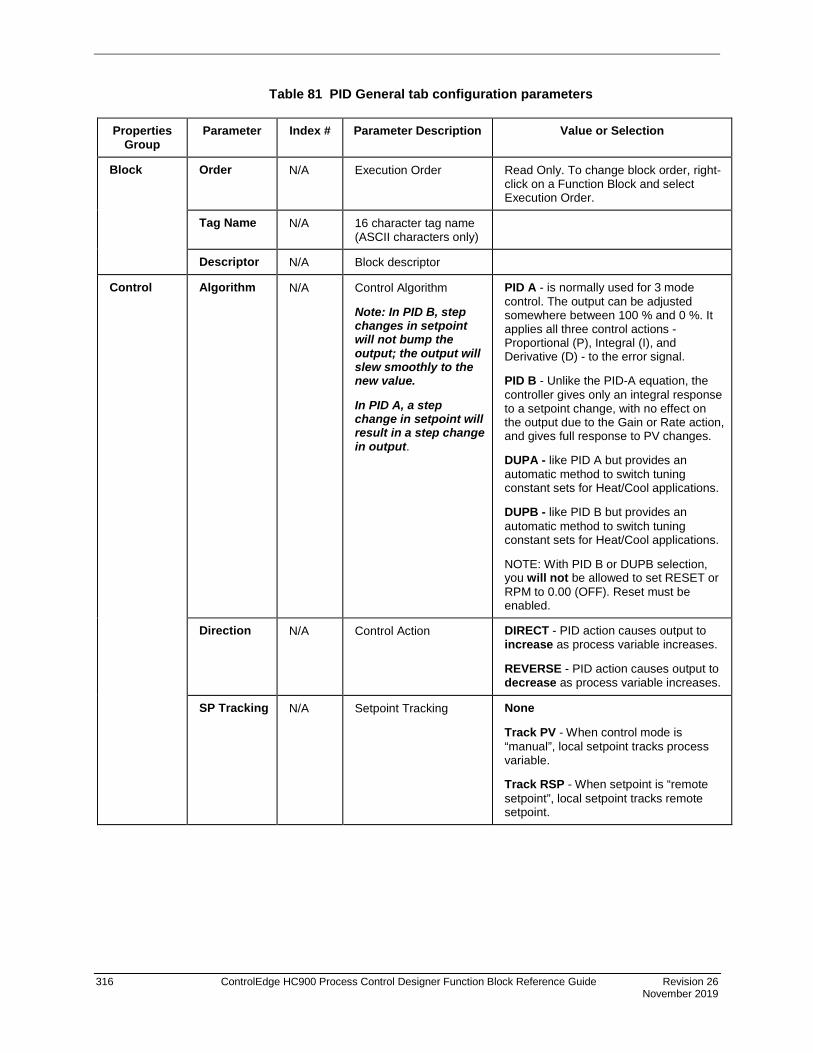
316 ControlEdge HC900 Process Control Designer Function Block Reference Guide Revision 26 November 2019
Table 81 PID General tab configuration parameters
Properties Group
Parameter Index # Parameter Description Value or Selection
Block Order N/A Execution Order Read Only. To change block order, right-click on a Function Block and select Execution Order.
Tag Name N/A 16 character tag name (ASCII characters only)
Descriptor N/A Block descriptor
Control Algorithm N/A Control Algorithm
Note: In PID B, step changes in setpoint will not bump the output; the output will slew smoothly to the new value.
In PID A, a step change in setpoint will result in a step change in output.
PID A - is normally used for 3 mode control. The output can be adjusted somewhere between 100 % and 0 %. It applies all three control actions -Proportional (P), Integral (I), and Derivative (D) - to the error signal.
PID B - Unlike the PID-A equation, the controller gives only an integral response to a setpoint change, with no effect on the output due to the Gain or Rate action, and gives full response to PV changes.
DUPA - like PID A but provides an automatic method to switch tuning constant sets for Heat/Cool applications.
DUPB - like PID B but provides an automatic method to switch tuning constant sets for Heat/Cool applications.
NOTE: With PID B or DUPB selection, you will not be allowed to set RESET or RPM to 0.00 (OFF). Reset must be enabled.
Direction N/A Control Action DIRECT - PID action causes output to increase as process variable increases.
REVERSE - PID action causes output to decrease as process variable increases.
SP Tracking N/A Setpoint Tracking None
Track PV - When control mode is “manual”, local setpoint tracks process variable.
Track RSP - When setpoint is “remote setpoint”, local setpoint tracks remote setpoint.

Revision 26 ControlEdge HC900 Process Control Designer Function Block Reference Guide 317 November 2019
START/RESTART tab
Table 82 PID Start/Restart tab configuration parameter
Modes and Setpoints
Permitted Mode
MAN 8
AUTO 9
Mode permitted for the initial start and power up mode.
Manual Automatic May select both, must select one.
Permitted Setpoint
LSP 10
RSP 11
Setpoint permitted for the initial start and power up mode.
Local Setpoint Remote Setpoint May select both, must select one.
Initial Mode N/A Mode at NEWSTART
Newstart is the first scan cycle following the cold start of the controller
Manual Automatic Select one
Setpoint for Initial Mode
N/A Setpoint at NEWSTART
Newstart is the first scan cycle following the cold start of the controller
Local Setpoint Remote Setpoint Select one
Power up Mode
N/A Mode at power up Manual Retain Last Mode Same mode (auto or manual) Select one
Power up Setpoint
N/A Setpoint at power up Local Setpoint Retain Last LSP/RSP Same Setpoint (LSP or RSP) Select one

318 ControlEdge HC900 Process Control Designer Function Block Reference Guide Revision 26 November 2019
Power Up Out
Power Up Out
N/A Output at Power up LAST OUT - Same as at power down. FAILSAFE - Failsafe output value.
Failsafe Out 16 Failsafe Output Value –5 % to 105 %
Initial Setpoint Value
Use initial LSP
49 Use Initial Local Setpoint
Click on radio button to select
Initial LSP Value
50 Initial Local Setpoint Value
Enter Initial Local Setpoint Value
High Output Limit Select
Use Limit Control -Limit Value
51 High Limit Override
See NOTE 1
Click radio button to select.
Delay Time 52 Delay Time for High Limit Output Select
Enter time in minutes to use TRV as the output high limit. See NOTE 1.
Ramp Rate 53 Ramp Rate for High Limit Output Select
Enter Rate in % per minute to ramp the default output high limit after delay time expires.
Note 1. When ON, the HiLimOvr parameter causes the meaning of TRC and TRV to be redefined for process startup rate control. In this case, TRC set ON causes the algorithm to calculate a value to override the default output high limit.
The initial value of the limit override comes from TRV. This value is held until the configured delay time expires. A delay time of zero means delay indefinitely. In this case, the output high limit will track the value on TRV until such time that TRC returns to OFF.
When the delay time expires, the output limit will ramp to the default configured value and the configured ramp rate. When the ramped output limit equals or exceeds the default configured value, the output limit override status is set OFF and the default value is used. A ramp rate of zero will cause immediate termination of the high output limit override.
A transition of the TRC input to OFF at any time will terminate the output limit override function and restore the limit to the default configured value. The TRC input must transition to OFF before the output limit override function can be started again.
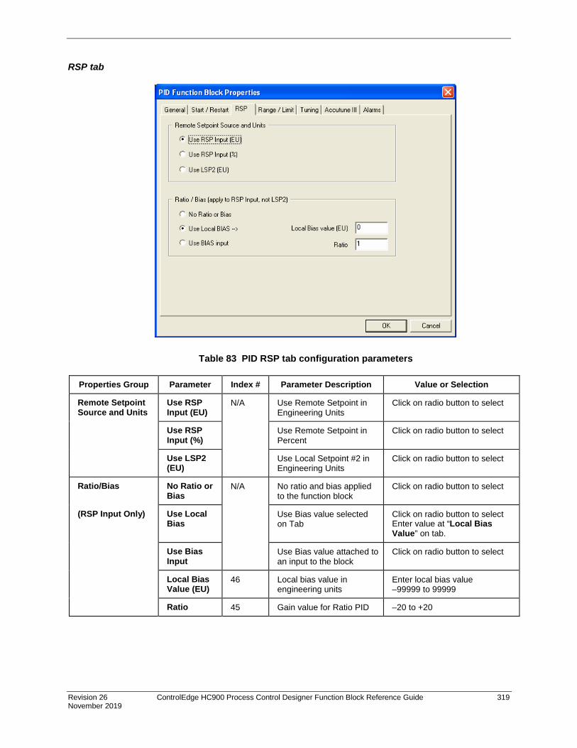
Revision 26 ControlEdge HC900 Process Control Designer Function Block Reference Guide 319 November 2019
RSP tab
Table 83 PID RSP tab configuration parameters
Properties Group Parameter Index # Parameter Description Value or Selection
Remote Setpoint Source and Units
Use RSP Input (EU)
N/A Use Remote Setpoint in Engineering Units
Click on radio button to select
Use RSP Input (%)
Use Remote Setpoint in Percent
Click on radio button to select
Use LSP2 (EU)
Use Local Setpoint #2 in Engineering Units
Click on radio button to select
Ratio/Bias No Ratio or Bias
N/A No ratio and bias applied to the function block
Click on radio button to select
(RSP Input Only) Use Local Bias
Use Bias value selected on Tab
Click on radio button to select Enter value at “Local Bias Value” on tab.
Use Bias Input
Use Bias value attached to an input to the block
Click on radio button to select
Local Bias Value (EU)
46 Local bias value in engineering units
Enter local bias value –99999 to 99999
Ratio 45 Gain value for Ratio PID –20 to +20

320 ControlEdge HC900 Process Control Designer Function Block Reference Guide Revision 26 November 2019
RANGE/LIMIT tab

Revision 26 ControlEdge HC900 Process Control Designer Function Block Reference Guide 321 November 2019
Table 84 PID Range/limit tab configuration parameters
Properties Group Parameter Index # Parameter Description Value or Selection
Ranging PV High Range
4 PV High Range Value –99999 to 99999
PV Low Range
5 PV Low Range Value –99999 to 99999
Display Decimal Places
N/A Number of digits to display after decimal point.
0 to 5
Units N/A Text to display for EU 6 characters
DEV Bar Range (EU)
N/A Deviation Bar Range on the Operator Interface
–99999 to 99999
Limiting SP High Limit
17 Setpoint High Limit Value - prevents the local and remote setpoints from going above the value set here.
–99999 to 99999
SP Low Limit
18 Setpoint Low Limit Value - prevents the local and remote setpoints from going below the value set here.
–99999 to 99999
Out High Limit
20 Output High Limit Value - is the highest value of output beyond which you do not want the automatic output to exceed
–5 % to 105 %
Out Low Limit
21 Output Low Limit Value - is the lowest value of output beyond which you do not want the automatic output to exceed
–5 % to 105 %
SP Rate Down
41 Setpoint Rate Down value - when making a setpoint change, this is the rate at which setpoint will change from the original setpoint down to the new one.
0 (off) to 9999 (eu/min)
SP Rate Up 42 Setpoint Rate Up value - when making a setpoint change, this is the rate at which setpoint will change from the original setpoint up to the new one.
0 (off) to 9999 (eu/min)

322 ControlEdge HC900 Process Control Designer Function Block Reference Guide Revision 26 November 2019
TUNING tab
ATTENTION
Use of Tune SET 1 or 2 can be selected via input (SWI) from the Loop Switch block output (SWO) or, in the case of DUP_A or DUP_B, automatically depending on the value of the previous output (≥ 50 % or < 50 %).
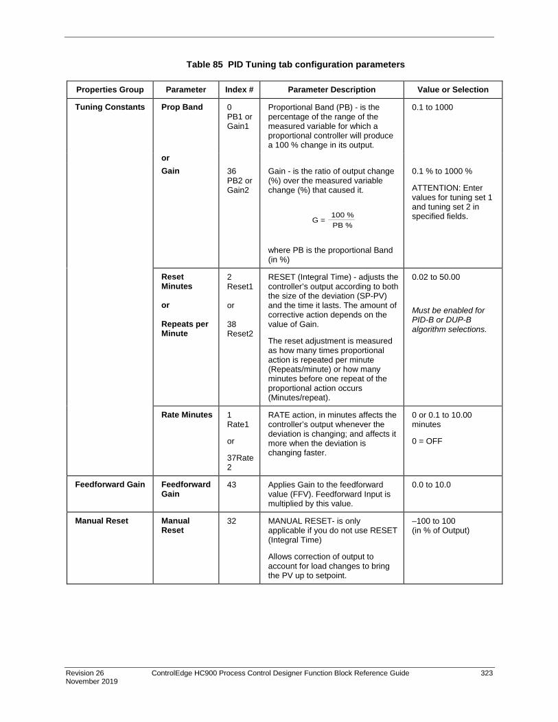
Revision 26 ControlEdge HC900 Process Control Designer Function Block Reference Guide 323 November 2019
Table 85 PID Tuning tab configuration parameters
Properties Group Parameter Index # Parameter Description Value or Selection
Tuning Constants Prop Band 0 PB1 or Gain1
Proportional Band (PB) - is the percentage of the range of the measured variable for which a proportional controller will produce a 100 % change in its output.
0.1 to 1000
or Gain 36
PB2 or Gain2
Gain - is the ratio of output change (%) over the measured variable change (%) that caused it.
G =100 %PB %
where PB is the proportional Band (in %)
0.1 % to 1000 %
ATTENTION: Enter values for tuning set 1 and tuning set 2 in specified fields.
Reset Minutes or Repeats per Minute
2 Reset1 or 38 Reset2
RESET (Integral Time) - adjusts the controller’s output according to both the size of the deviation (SP-PV) and the time it lasts. The amount of corrective action depends on the value of Gain.
The reset adjustment is measured as how many times proportional action is repeated per minute (Repeats/minute) or how many minutes before one repeat of the proportional action occurs (Minutes/repeat).
0.02 to 50.00
Must be enabled for PID-B or DUP-B algorithm selections.
Rate Minutes 1 Rate1
or
37Rate2
RATE action, in minutes affects the controller’s output whenever the deviation is changing; and affects it more when the deviation is changing faster.
0 or 0.1 to 10.00 minutes
0 = OFF
Feedforward Gain Feedforward Gain
43 Applies Gain to the feedforward value (FFV). Feedforward Input is multiplied by this value.
0.0 to 10.0
Manual Reset Manual Reset
32 MANUAL RESET- is only applicable if you do not use RESET (Integral Time)
Allows correction of output to account for load changes to bring the PV up to setpoint.
–100 to 100 (in % of Output)

324 ControlEdge HC900 Process Control Designer Function Block Reference Guide Revision 26 November 2019
ACCUTUNEIII tab
Table 86 PID Accutune III tab configuration parameters
Properties Group Parameter Index # Parameter Description Value or Selection
Accutune III Type Disabled N/A Disables Accutune III Click on radio button to select.
Cycle Tuning
Tuning parameter values are derived from the process response to the resultant action of causing the PV to oscillate about the SP value. (Note 1 - Page 326)
Click on radio button to select.
SP Tuning Tuning based on the process response to a SP change. (Note 2 – Page 326)
Click on radio button to select.
SP Tuning Direction (For SP Tuning selection)
UP
Down N/A The selection of either UP or
DOWN results in the SP Change value added or subtracted from the present SP value.
Click on radio button to select.
SP Process
(For SP Tuning selection)
Process Gain
SPTune Change
16
57
Gain identification value for the process. This value is used to estimate the size of the initial output step for a SP Tune.
This defines the value of the initial output step change that is used as the target for process identification.
Range is 0.10 to 10.0 Normal value is 1.
Range is: 5 to 15 percent.

Revision 26 ControlEdge HC900 Process Control Designer Function Block Reference Guide 325 November 2019
PV Adaptive Tuning
Disable N/A Disables PV Adaptive tune Click on radio button to select.
Enable N/A This method adapts a tuned process to changing system characteristics over time. When the PV deviates from the SP by a certain amount for any reason. (Note 3 – Page 326)
Click on radio button to select.
Tuning Criteria Normal N/A Conservative tuning designed to calculate critically damped tuning parameter values that produce minimal overshoot.
Click on radio button to select.
Fast N/A More aggressive tuning than Normal, designed to calculate under damped parameter values providing faster control to the setpoint but may have some overshot.
Duplex Tuning
(Active for Algorithm DUPA or DUPB on General Tab with Cycle Tuning)
Disable
Manual
Automatic
N/A Disable -Duplex type tuning is disabled and simplex type tuning is used instead.
Manual - Tuning must be initiated manually for each side. The current LSP or RSP value is used as the target SP for the desired heat or cool side tuning. For the heat side, the output cycles between 50 percent and the high output limit and for the cool side the output cycles between 50 percent and the low output limit. Tuning values are calculated and stored only for the side tuned.
Heat and Cool tuning are sequentially performed automatically. During the operation of this tuning the target SP used is the mid point between the high output limit and 50 percent for the heat side and the low output limit and 50 percent for the cool side. During tuning for each side the cycling of the output results in the PV oscillating around the target SP value. From the data gathered during the oscillations, tuning values are calculated and stored for each side. After tuning on both sides is completed, the process SP is returned to the value of the last SP used prior to the initiation of the tuning procedure.
Click on radio button to select.

326 ControlEdge HC900 Process Control Designer Function Block Reference Guide Revision 26 November 2019
Enable Fuzzy Overshoot
Suppression Click on block to select
34 Fuzzy Overshoot Suppression minimizes overshoot after a setpoint change or a process disturbance.
The fuzzy logic observes the speed and direction of the PV signal as it approaches the setpoint and temporarily modifies the internal controller response action as necessary to avoid an overshoot.
There is no change to the PID algorithm, and the fuzzy logic does not alter the PID tuning parameters.
This feature can be independently Enabled or Disabled as required by the application to work with “TUNE” On-Demand tuning.
ATTENTION
Accutune III is an On-demand tune only. You must provide a 0 to 1 transition to start another tuning cycle. The tuning will disturb the output to evaluate the tuning constants required.
Note 1: CYCLE TUNING - This tuning method uses the measured ultimate gain and period to produce tuning parameter values. Cycle tuning does not distinguish between process lags and always results in gain based on PV amplitude and calculates values of Reset and Rate based on time of the SP crossings (The Reset value is always 4x the Rate value.) This method does not require a stable process initially and the process may be moving. Cycle tuning is applicable to Three Position Step control and can be used for integrating processes (level control).
Note 2: SP TUNING - When initiated the control loop is put into an initial temporary manual state until the process characteristics are identified. This period may last up to a minute. During this time the Tune status shows Not Ready, then an initial output step is made using the preconfigured size and direction parameters along with the preset output value. The resultant process action is used to determine the tuning parameters and once the process identification has completed, the loop is returned to automatic control.
Note 3: PV ADAPTIVE TUNING - This method adapts a tuned process to changing system characteristics over time. When the PV deviates from the SP by a certain amount for any reason, the adaptive tuning algorithm becomes active and begins to observe the resulting PV action. If the process becomes unstable and oscillates, PV Adaptive Tuning eventually brings the process into control by retuning parameter values (as needed) using a systematic approach defined by an expert based method of tuning rules. Should the process not oscillate but be observed as too fast or sluggish, a different expert rules set is applied to result in the slowing down or speeding up of the process by adjusting certain tuning parameter values. This method continuously learns the process as PV deviations are observed and adapts the tuning parameters to the process response.

Revision 26 ControlEdge HC900 Process Control Designer Function Block Reference Guide 327 November 2019
ALARMS tab

328 ControlEdge HC900 Process Control Designer Function Block Reference Guide Revision 26 November 2019
Table 87 PID Alarms tab configuration parameters
Properties Group Parameter Index # Parameter Description Value or Selection
Alarm 1 Setpoint 1 23 Alarm 1 Setpoint 1 Value - this is the value at which you want the alarm type chose below to activate
–99999 to 99999 in Engineering Units
Within the PV range when alarm type is PV or SP
Within PV span when alarm type is DEV
–5 % to 105 % when alarm type is output.
Type N/A Alarm 1 Setpoint 1 Type - select what you want Alarm 1 Setpoint 1 to represent.
Selections:
NO ALARM
PV_HIGH High PV Alarm
PV_LOW Low PV Alarm
DEV_HIGH High Deviation alarm
DEV_LOW Low Deviation alarm
SP_HIGH High Setpoint alarm
SP_LOW Low Setpoint alarm
OUT_HIGH High Output alarm
OUT_LOW Low Output alarm
Setpoint 2 24 Alarm 1 Setpoint 2 Value Same as Alarm 1 Setpoint 1
Type N/A Alarm 1 Setpoint 2 Type Same as Alarm 1 Setpoint 1
Alarm 2 Setpoint 1 25 Alarm 2 Setpoint 1 Value Same as Alarm 1 Setpoint 1
Type N/A Alarm 2 Setpoint 1 Type Same as Alarm 1 Setpoint 1
Setpoint 2 26 Alarm 2 Setpoint 2 Value Same as Alarm 1 Setpoint 1
Type N/A Alarm 2 Setpoint 2 Type Same as Alarm 1 Setpoint 1
Alarm Hysteresis
% 31 Alarm Hysteresis in % 0 % to 5 %

Revision 26 ControlEdge HC900 Process Control Designer Function Block Reference Guide 329 November 2019
Example 1 - Basic PID configuration example Figure 74 shows a Function Block Diagram using a simplified PID Configuration (reference only) and its basic Configuration.
Figure 74 PID function block example
Analog Input block
PID Block (Simplified)
Analog Output Block
Analog Variable- used to provide a remote setpoint value.
Remote Setpoint Input
Alarm Outputs (Digital Signal)
FAIL

330 ControlEdge HC900 Process Control Designer Function Block Reference Guide Revision 26 November 2019
Example 2 - Duplex control - PID with heat/cool (duplex) output
Figure 75 Duplex control example

Revision 26 ControlEdge HC900 Process Control Designer Function Block Reference Guide 331 November 2019
Example 3 - Cascade control The Cascade loop uses 2 PID blocks with the Back Calculation pin of the secondary connected to the primary loop. This transfers values back to the primary loop to adjust the PID for changes due to manual control.
Figure 76 Cascade control example

332 ControlEdge HC900 Process Control Designer Function Block Reference Guide Revision 26 November 2019
Example 4 - Ratio control
Figure 77 Ratio control example
The RATIO control loop requires selection of theremote SP of the PID for ratio control. The Ratioand Bias values are available for adjustmentfrom the Control Setup screen of the OperatorInterface. The Bias may be a local value or comefrom an external source such as an O2 analyzertrim arrangement. You may elect to use % forthe ratioed inputs (typically for boilerapplications) or Eng. Units (EU) (for feed flows toa reactor, for example).
External Bias Input
Air (controlled variable)= Ratio x Fuel (RSP, or wild variable) + BIAS

Revision 26 ControlEdge HC900 Process Control Designer Function Block Reference Guide 333 November 2019
Example 5 - Cascade control of a boiler drum level - basic
Figure 78 Cascade control of a boiler drum level - basic
Steam Drum
M
LT 1
Feedwater Flow
FT 2
SteamNote: All physicalconnections are by I/O cards
FAIL FAIL

334 ControlEdge HC900 Process Control Designer Function Block Reference Guide Revision 26 November 2019
Example 6 - Cascade control of a boiler drum level - 3 element feedwater control
Figure 79 Cascade control of a boiler drum level - 3 element feedwater control
M
Feedwater Flow
FT 2
SteamNote: All physicalconnections are by I/O cards
LT 2
LT 1
Steam Drum
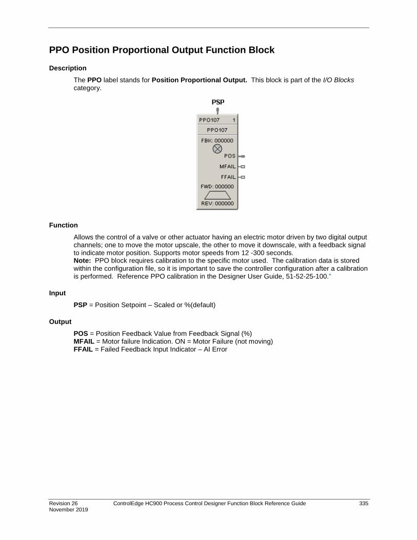
Revision 26 ControlEdge HC900 Process Control Designer Function Block Reference Guide 335 November 2019
PPO Position Proportional Output Function Block
Description The PPO label stands for Position Proportional Output. This block is part of the I/O Blocks category.
Function Allows the control of a valve or other actuator having an electric motor driven by two digital output channels; one to move the motor upscale, the other to move it downscale, with a feedback signal to indicate motor position. Supports motor speeds from 12 -300 seconds. Note: PPO block requires calibration to the specific motor used. The calibration data is stored within the configuration file, so it is important to save the controller configuration after a calibration is performed. Reference PPO calibration in the Designer User Guide, 51-52-25-100.”
Input PSP = Position Setpoint – Scaled or %(default)
Output POS = Position Feedback Value from Feedback Signal (%) MFAIL = Motor failure Indication. ON = Motor Failure (not moving) FFAIL = Failed Feedback Input Indicator – AI Error
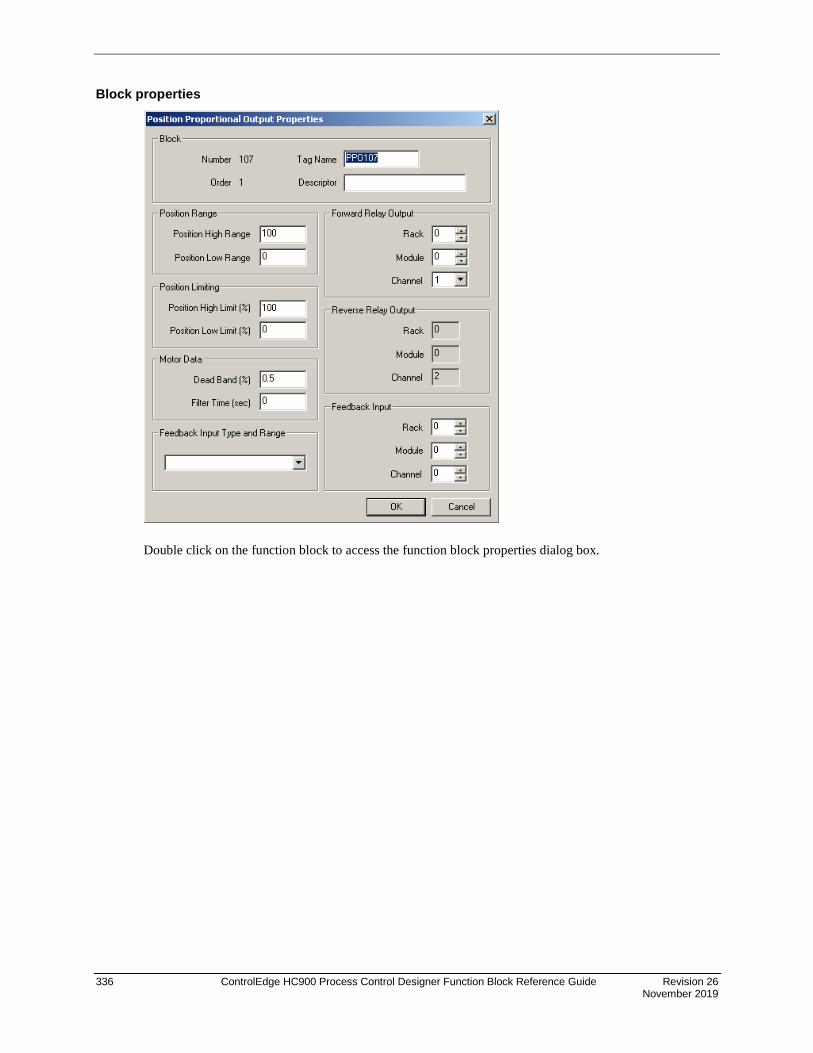
336 ControlEdge HC900 Process Control Designer Function Block Reference Guide Revision 26 November 2019
Block properties
Double click on the function block to access the function block properties dialog box.

Revision 26 ControlEdge HC900 Process Control Designer Function Block Reference Guide 337 November 2019
Configurable Parameters
Table 88 Position Proportional Motor Control
Parameter Index # Parameter Description Value or Selection
Block Order N/A Execution Order for Block Read Only. To change block order, right-click on a Function Block and select Execution Order.
Position Setpoint High Range
4 Position Setpoint High Range Value Engineering Unit - value of input that corresponds to 100 % output value
-99999 to 999999 Default = 100
Position Setpoint Low Range
5 Position Setpoint Low Range Value Engineering Unit - value of input that corresponds to 0 % output value
-99999 to 999999 Default = 0.0
High Position Limit
20 High Position Limit in Percent 0 to 100% Default = 100%
Low Position Limit
21 Low Position Limit in Percent 0 to 100% Default = 0%
Deadband (%)
8 Adjustable gap between forward and reverse motor operation (the range over which the output can change before a relay is energized)
0.5 to 5%
Filter Time (sec)
10 A software digital filter is provided to smooth the slidewire feedback input.
0 to 3 seconds. 0=no filter
Feedback Input type and range
3 Input type choices for the position feedback
4 to 20 mA 0 to 20 mA 0 to 1 V 0 to 5 V Slidewire 250 to 1250 ohms Slidewire < 250 ohms Slidewire 1250 to 4000 ohms* Slidewire 4000 to 6500 ohms* *Version 4.1 or later.
FORWARD RELAY OUTPUT
Parameter Rack # Parameter Description Value or Selection
Rack Address
1
This is the address of the selected Rack.
1 to 12.
I/O Module Address
Address of selected I/O module 1 to 12
Channel Address
Table continued
Channel on selected I/O Module Odd number 1 thru 15.*
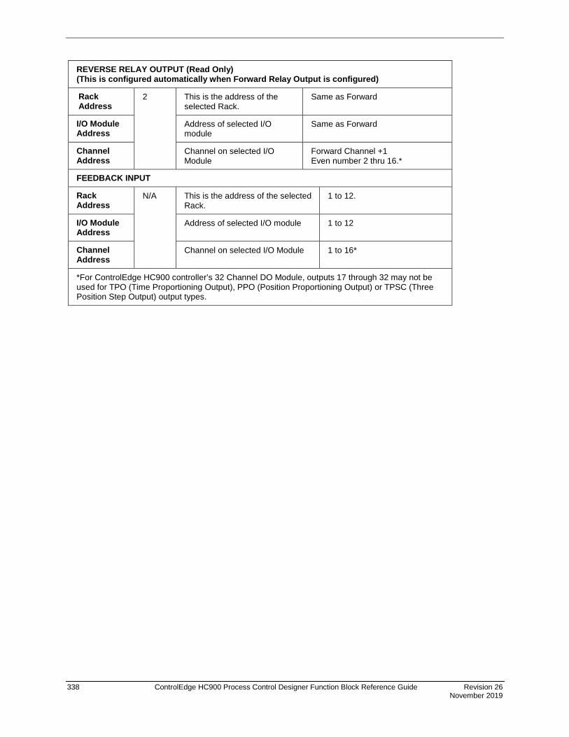
338 ControlEdge HC900 Process Control Designer Function Block Reference Guide Revision 26 November 2019
REVERSE RELAY OUTPUT (Read Only) (This is configured automatically when Forward Relay Output is configured)
Rack Address
2 This is the address of the selected Rack.
Same as Forward
I/O Module Address
Address of selected I/O module
Same as Forward
Channel Address
Channel on selected I/O Module
Forward Channel +1 Even number 2 thru 16.*
FEEDBACK INPUT
Rack Address
N/A
This is the address of the selected Rack.
1 to 12.
I/O Module Address
Address of selected I/O module 1 to 12
Channel Address
Channel on selected I/O Module 1 to 16*
*For ControlEdge HC900 controller’s 32 Channel DO Module, outputs 17 through 32 may not be used for TPO (Time Proportioning Output), PPO (Position Proportioning Output) or TPSC (Three Position Step Output) output types.

Revision 26 ControlEdge HC900 Process Control Designer Function Block Reference Guide 339 November 2019
Example
Figure 80 Position Proportional Motor Control
Analog Input Module AC Output Module
Actuator
R
F
F
R
R
F

340 ControlEdge HC900 Process Control Designer Function Block Reference Guide Revision 26 November 2019
PSYC Psychrometric Calculations Function Block
Description The PSYC label stands for Psychrometric Calculations. This block is part of the HVAC category.
Function This block calculates the Humidity Ratio, Enthalpy, Dew point temperature, Wet bulb temperature and Absolute Moisture based on the input Dry bulb temperature (DRY), Relative Humidity (RH) and Atmospheric Pressure (ATMP). A single configurable parameter specifies if inputs and outputs use metric system units.
ATTENTION
The wet bulb temperature output is updated only once for every three executions of the block.
Inputs DRY = Dry bulb air temperature – Range: -40 – 140 degrees F or -40 – 60 degrees C
RH = Air relative humidity – Range: 1.0 – 99.9% RH.
ATMP = Barometric Pressure – Range: 12.5 – 15.7 psi. or 861.84 – 1082.47 millibars. When this pin is not connected the calculations use a default value of 14.696 psi. or 1,013.25 millibars.
Note: If any of the above inputs are outside of the specified ranges, they are set to the upper or lower range as appropriate.
Outputs HRATIO = Humidity Ratio – lb/lb or kg/kg
ENTH = Enthalpy – btu/lb or kJ/kg
DEWPT = Dew point temperature – degrees F or degrees C
WET = Wet bulb temperature – degrees F or degrees C
ABSM = Absolute moisture – gr/lb or gr/kg
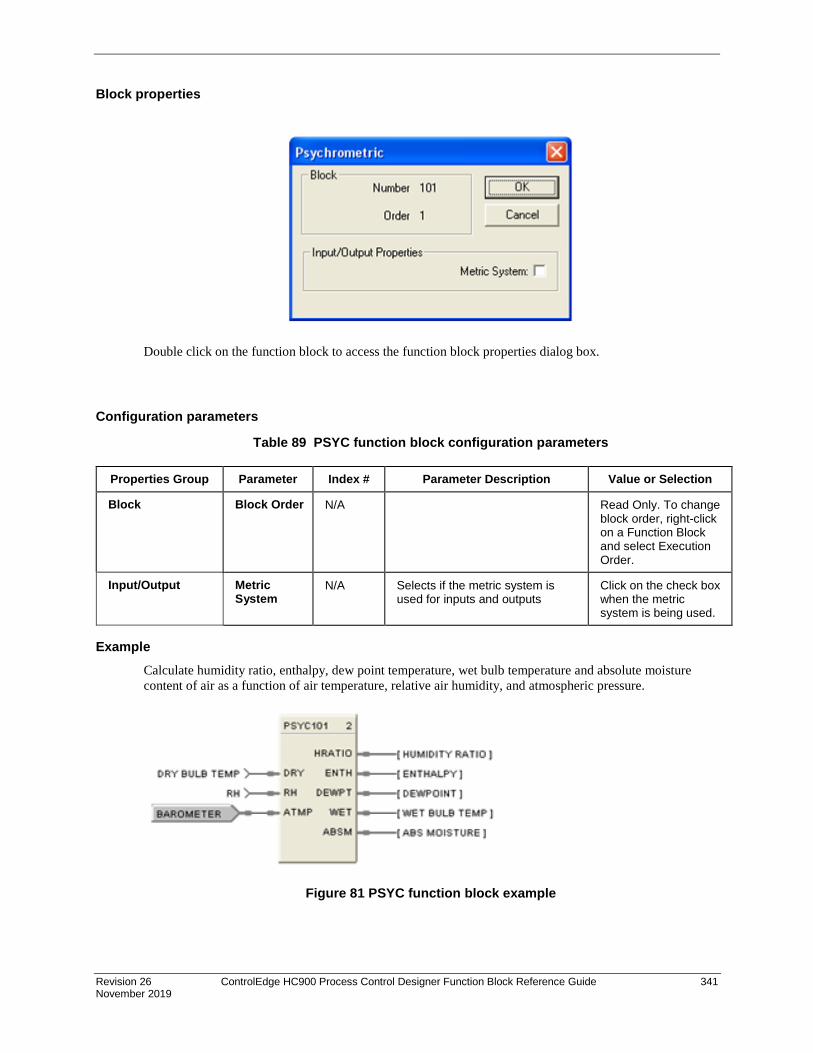
Revision 26 ControlEdge HC900 Process Control Designer Function Block Reference Guide 341 November 2019
Block properties
Double click on the function block to access the function block properties dialog box.
Configuration parameters
Table 89 PSYC function block configuration parameters
Properties Group Parameter Index # Parameter Description Value or Selection
Block Block Order N/A Read Only. To change block order, right-click on a Function Block and select Execution Order.
Input/Output Metric System
N/A Selects if the metric system is used for inputs and outputs
Click on the check box when the metric system is being used.
Example Calculate humidity ratio, enthalpy, dew point temperature, wet bulb temperature and absolute moisture content of air as a function of air temperature, relative air humidity, and atmospheric pressure.
Figure 81 PSYC function block example

342 ControlEdge HC900 Process Control Designer Function Block Reference Guide Revision 26 November 2019
PTMR Periodic Timer Function Block
Description The PTMR label stands for Periodic Timer.
OR
This block is part of Logic and Fast Logic categories.
Function (1 or 2) 4. Time/Cycle: Generates a discrete output pulse at a specified start time based on the real-time clock and at
specified time periods thereafter. Start Times = Month, Day, Hour, Minute, Second Cycle Periods = Monthly, Weekly, Daily Time Cycle Periods Within a Day = Hours (0-23) Minutes (0-59) Seconds (0-59) NOTE: Once started, period repeats until reset.
5. Reset Cycle: Generates a digital output based on a digital input and at regular intervals thereafter. Time Start = ON to OFF transition of reset input. Cycle Time Period = Hours (0-23) Minutes (0-59) Seconds (0-59)
Input RST = Reset/Enable (ON = Output disable, OFF = Output enable)
Output EVENT= OUT Logic State. Output turns ON for one scan cycle when elapsed time matches setpoint time (One-shot).
Block properties
Double click on the function block to access the function block properties dialog box.

Revision 26 ControlEdge HC900 Process Control Designer Function Block Reference Guide 343 November 2019
Configuration parameters
Table 90 PT function block configuration parameters
Properties Group Parameter Index # Parameter Description Value or Selection
Block Block Order N/A Read Only. To change block order, right-click on a Function Block and select Execution Order.
Period Monthly N/A Output turns ON once a month for one scan cycle. If the current month’s last day is less than 31 it will turn ON on the last day of the month.
Reset/Enable: ON = Hold off output OFF = Run
Enter START - Day (Days >31 = 31), Hour, Minute, Seconds
Weekly N/A Output turns ON once a week for one scan cycle.
Reset/Enable: ON = Hold off output OFF = Run
Enter at START - Day (Monday through Sunday), Hour, Minute, Seconds
Daily N/A Output turns ON once a day for one scan cycle.
Reset/Enable: ON = Hold off output OFF = Run
Enter at START - Hour, Minute, Seconds
Time/Cycle N/A Timer starts at a specific time of day then output pulses on/off on a time interval. Once started, start time is ignored until reset.
Reset Input: ON = stops cycle and holds off start OFF = enables start time
Enter at START - Hour, Minute, Seconds
Enter at CYCLE - Hour, Minute, Second
Reset/Cycle N/A Timer starts on an ON (1) to OFF (0) transition of the reset input, then output pulses on/off on a time interval. Once started, the cycle continues until the reset turns on.
Reset Input: ON = stops cycle and holds off start OFF = Output turns ON for one scan cycle at ON to OFF transition and cycle begins.
Enter at CYCLE - Hour, Minute, Second

344 ControlEdge HC900 Process Control Designer Function Block Reference Guide Revision 26 November 2019
Properties Group Parameter Index # Parameter Description Value or Selection
Start Hour N/A Start Hour 0 through 23
Minute N/A Start Minute 0 through 59
Second N/A Start Second 0 through 59
Day N/A Start Day Monthly - 1 - 31 (Days >31 = 31) If the current month’s last day is less than 31 it will turn ON on the last day of the month.
Weekly -Monday through Sunday
Cycle Hour N/A Cycle Hour 0 through 23
Minute N/A Cycle Minutes 0 through 59
Second N/A Cycle Seconds 0 through 59
Example Figure 82 shows a Function Block Diagram using a PT function block. An OFF delay timer block output is ON as long as the RST input is logic HI (ON). It can be used for time duration but must be triggered by an ON to OFF transition on the Reset input. This can be accomplished using Trigger blocks (TRIG) to create one-shot pulses which last one scan cycle. The fast logic trigger pulse will last 100 ms. while the normal logic trigger pulse will last the complete scan cycle for analog blocks. Use according to application need. A Periodic Timer (PT) output pulse may also be used to start the timer for the OFF delay for time duration.
Figure 82 PT function block example
Off delay
AND4 output
TRIG1 output
OFDT2 output
Timing Diagram

Revision 26 ControlEdge HC900 Process Control Designer Function Block Reference Guide 345 November 2019
QDT Quadrature Function Block
Description The QDT stands for Quadrature.
This block is part of the I/O Blocks category.
Function This function block measures/controls movement of an actuated device. A digital encoder connected to the actuated device produces two channels (A and B) of square waves, offset 90 degrees. Quadrature refers to the 4 logic states between these two waves. The rising edge to rising edge (cycle) on channel A or B indicates that one set of bars on the encoder have passed by its optical sensor. By counting these passing rising edges the Quadrature block measures
1) distance (or whatever engineering units are being controlled by the device),
2) position (that is, distance from a marker designated as zero),
3) direction (indicated by the sequence between the two channels; A leads B or B leads A).
More precise measurement/control is done by counting more logic states determined by the two waves. For example, the quadrature state of channels A and B create four unique logic states. When these four unique logic states are decoded, the resolution obtained is 4 times (4X) the resolution of the encoder. So with this in mind 250 cycles would yield 1000 quadrature states.
Inputs BIAS = Value added to the output in EU.
ENBIAS = Enable Bias. When ON the bias is added to the output. Input is ignored if not connected and default state is enabled.
ICLR = Index Clear Enable. When this is ON it enables the module’s Index input so that the first OFF to ON transition of Index input resets the output to zero (plus bias, if enabled).
^RST = OFF to ON transition resets the output to zero (plus bias, if enabled).
^CLFG = OFF to ON transition clears the CNTERR and RNGERR flags to zero.

346 ControlEdge HC900 Process Control Designer Function Block Reference Guide Revision 26 November 2019
Outputs INC = ON when count is incrementing; OFF when count is stopped or decrementing.
DEC = ON when count is decrementing; OFF when count is stopped or incrementing.
INDEX = ON when index pulse is detected and ICLR are asserted.
CNTERR = ON when the count on the module overflows or underflows.
RNGERR = ON when the count on the module surpasses the range limits.
CDIS = ON when the PFQ module detects a cable disconnect.
FAIL = ON when module is failed. Caused by INC and DEC both ON.
OUT = Count in EUs.
Notes To ensure correct counting, the block counts only pulses of a certain wavelength (>2.25 uS); smaller pulses caused by noise are rejected. Additionally only a single transition of Channel A (Input 1) and Channel B (Input 2) may occur; a transition on both channels simultaneously cases an invalid count.
Configuration Parameters
Table 91 QDT parameters
Properties Group Parameter Index # Parameter Description Value or Selection
Block Order N/A Execution Order for Block Read Only. To change block order, right-click on a Function Block and select Execution Order.
Input A Address Rack 0 This is the address of the selected Rack.
Enter a value: from 1 to 5.
Module 0 Slot location of the PFQ module Enter a value: from 1 to 12
Channel 0 Channel A on the PFQ Module 1 (not selectable)
Input B Address Rack 0 This is the address of the selected Rack.
Automatically set to same as Input A.
Module 0 Slot location of the PFQ module Automatically set to same as Input A.
Channel 0 Channel B on the PFQ Module 2 (not selectable)
Encoder Range Pulses per EU
1 Number of pulses per EU of the variable being measured/counted. Be sure to factor in your Quadrature Mode setting (X1, X2, X4).
Enter a value.
Upper Range Limit
3 Upper range limit of EU. Enter a value.
Lower Range Limit
4 Lower range limit of EU. Enter a value.

Revision 26 ControlEdge HC900 Process Control Designer Function Block Reference Guide 347 November 2019
Properties Group Parameter Index # Parameter Description Value or Selection
Control Configuration
Quadrature Mode
2 Resolution of counter. The quadrature code produced by encoders has 4 state changes (edges) per quadrature cycle (one per ¼ cycle). A 250 CPR encoder has 250 cycles, (1000 pulses) per revolution. X1 decoding means that the external electronics pulses once per full cycle. X2 pulses twice per cycle. X4 pulses every quadrature state.
X1: One pulse per cycle
X2: Two pulses per cycle
X4: Four pulses per cycle
Failsafe Use Value 5 When FAIL is ON output is set to this value.
Click to select, enter a value.
Up scale 6 When FAIL is ON output is set to Upper Range Limit.
Click to select.
Down scale 6 When FAIL is ON output is set to Lower Range Limit.
Click to select.
HOLD 6 When FAIL is ON output is held. Click to select.
Example
Figure 83 Quadrature function block example
Quadrature Function used to measure the output of an encoder to determine the position of a traversing process.

348 ControlEdge HC900 Process Control Designer Function Block Reference Guide Revision 26 November 2019
RAI Function Block Description
The RAI label stands for Analog Input with Remote C/J.
This block is part of the I/O Blocks category.
Function This block is used only for Thermocouples when the thermocouple Cold Junction is in a remote location, i.e., NOT connected at the AI module. Cold Junction compensation is performed using the value presented at the RCJ input, which is a temperature value in degrees C of the remote junction and which will come from another AI block. CJ compensation and linearization is performed in the block producing a value in engineering units at the OUT pin. Fail status of the AI block measuring the Remote CJ can be applied to the RSTAT pin. (i.e. if the RCJ measurement Fails, the Thermocouple measurement fails)
Input Analog value from specified real I/O address. DIS = disable the AI channel RCJ = Remote CJ Value - This would come from an AI block Output. RSTAT = Remote CJ Status - This would come from the AI block Fail Pin.
Output OUT = Analog Input value in engineering units. WARN = Warning Input Indication - Sensor failure possibility. If AI input wiring or sensor exceeds 100 ohms of resistance, the WARNing pin will energize. There also will be a warning if the value of RCJ is outside the limits -30 to +90 C FAIL = Digital status of channel Digital Low (0) = OK Digital High (1) = Open sensor or failed input channel or RSTAT input is ON indicating a Failed RCJ AI block

Revision 26 ControlEdge HC900 Process Control Designer Function Block Reference Guide 349 November 2019
Configuration parameters
Table 92 Analog Input with Remote C/J configuration parameters
Parameter Index # Parameter Description Value or Selection Block Order N/A Execution Order for Block Read Only. To
change block order, right-click on a Function Block and select Execution Order.
Rack Address
This is the address of the selected Rack.
Enter a value from 1 to 12.
I/O Module Address
Address of selected I/O module Enter a value: from 1 to 12
Channel Address
Channel on selected I/O Module Enter a value: from 1 to 8 or 16.
T/C Type and Range
N/A Thermocouple Input types
Select an input from list box. See Table 93 for Input Type and Range

350 ControlEdge HC900 Process Control Designer Function Block Reference Guide Revision 26 November 2019
Parameter Index # Parameter Description Value or Selection Bad Channel Detection
N/A Check this to generate a hardware failure diagnostic if a bad AI channel is detected. If unchecked, a diagnostic will not be generated, which may be desirable for inputs used for monitoring only.
Click on block to select or deselect
Remote C/J N/A Set FAIL pin ON if RCJ value outside limits (-30 to 90 ºC)
Click on block to select or deselect
Disable Channel Output Value
8 The output value when the AI channel is disabled. Disable = ON
Enter a value Default = 0
Filter Time (sec)
2 A software digital filter is provided for the input designated to smooth the input. You can configure the first order lag time constant from 1 to 120 seconds. 0=no filter
Enter a value: 0 to 120 seconds
Bias 3 Bias is used to compensate the input for drift of an input value due to deterioration of a sensor, or some other cause.
Enter a value: -9999 to 99999
Failsafe Use Value
N/A Use the User value entered in the appropriate field.
Click on Radio button to select
Failsafe Use Value field
4 The output value to which the output will go to protect against the effects of failure of the equipment, such as, fuel shut-off if there is loss of flame in a furnace, or a sensor break.
Enter a value in Engineering Units -9999 to 99999
Downscale N/A OUT = Value of Low range implied by T/C input type.
Click on Radio button to select
Upscale OUT = Value of High range implied by T/C input type.
Click on Radio button to select
Burnout Check
N/A Burnout check enable
Click on block to select or deselect
Failsafe rules If the controller is unable to access the physical channel or the sensor is faulty, and:
• If Failsafe is “Use Value” Then OUT = Configured Failsafe value • If Failsafe is enabled and downscale Then OUT = Low Range Value of T/C input type • If Failsafe is enabled and upscale Then OUT = High Range Value of T/C input
type

Revision 26 ControlEdge HC900 Process Control Designer Function Block Reference Guide 351 November 2019
Table 93 ControlEdge HC900 Input Types and Ranges for RAI Function Block
Enum Type Range Low Range High EU
0 None
B -18 1815 C
B 0 3300 F
E -270 1000 C
E -454 1832 F
E -129 593 C
E -200 1100 F
J -18 871 C
J 0 1600 F
J -7 410 C
J 20 770 F
K -18 1316 C
K 0 2400 F
K -18 982 C
K 0 1800 F
K -29 538 C
K -20 1000 F
Ni-NiMo 0 1371 C
Ni-NiMo 32 2500 F
Ni-NiMo 0 682 C
Ni-NiMo 32 1260 F
NiMo-NiCo 0 1371 C
NiMo-NiCo 32 2500 F
NiMo-NiCo 0 682 C
NiMo-NiCo 32 1260 F
NiCroSil-NiSil -18 1300 C
NiCroSil-NiSil 0 2372 F
NiCroSil-NiSil -18 800 C
NiCroSil-NiSil 0 1472 F
R -18 1704 C

352 ControlEdge HC900 Process Control Designer Function Block Reference Guide Revision 26 November 2019
Enum Type Range Low Range High EU
R 0 3100 F
S -18 1704 C
S 0 3100 F
T -184 371 C
T -300 700 F
T -129 260 C
T -200 500 F
W_W26 -20 2320 C
W_W26 -4 4200 F
W5W26 -18 2316 C
W5W26 0 4200 F
W5W26 -18 1227 C
W5W26 0 2240 F
Example Figure 84 shows a Function Block Diagram configuration using an RAI function block.
RAI used for work temperature monitoring. Tag descriptors are used to identify the input. A digital tag connected to the fail output can alarm on an open sensor.
Figure 84 RAI function block example

Revision 26 ControlEdge HC900 Process Control Designer Function Block Reference Guide 353 November 2019
RACK Function Block
Description The RACK label stands for IO Rack Monitor.
This block is part of the Alarms/Monitor category.
Function The rack monitor block is a repository for controller/expansion rack I/O module information, including diagnostics.
The Rack function block provides Read/Write access to I/O Rack values. This block is always stored in the reserved block area (96 thru 100), are always in the configuration whether visible in the FBD or not. The total number is dependent on the controller type.
Each Rack monitor block has a unique identification number that is fixed for all configurations. The Rack number appears on the function block. The Number is specified as:
1 = Rack #1 (Main Rack) 2 = Rack #2 (Expansion Rack) 3 = Rack #3 (Expansion Rack) 4 = Rack #4 (Expansion Rack) 5 = Rack #5 (Expansion Rack) Right Click on Block icon to Monitor Block diagnostics.

354 ControlEdge HC900 Process Control Designer Function Block Reference Guide Revision 26 November 2019
Outputs RACK OK = On indicates Rack other than Good (Refer to Rack Diagnostics - Controller Diagnostics Status Indications in the Process Control Designer User Guide for Fault diagnostics)
HITEMP = On indicates High RJ Temperature detected on AI board (Refer to Expansion I/O Comm Diagnostics - Expansion I/O Comm Diagnostics Status Indications in the Process Control Designer User Guide for Fault diagnostics)
MODxx FAIL = On indicates Module other than Good. (I/O Module Diagnostics - I/O Module Diagnostics Status Indications in the Process Control Designer User Guide for Fault diagnostics)
The Status Indications will list the Error Status, possible causes of failure, controller actions, and User action to remove failure.
Example
Figure 85 Rack Monitor function block example

Revision 26 ControlEdge HC900 Process Control Designer Function Block Reference Guide 355 November 2019
RAMP Function Block
Description The RAMP label stands for Ramp.
This block is part of the Auxiliary category.
Function The RAMP function block is typically used for variable speed, valve position, and chemical feed control applications to reduce the output value as more external devices are enabled. For example: If one pump is running at 100 % and a second pump is enabled, the output value may be rescaled to 50 % by the pump 2 enable signal. The ramp block references an analog signal, and using four separate scales multiplexed together, provides a single analog output over a programmed range.
A configurable signal lag [LAG TIME] is applied to the referenced analog input (PV). The highest enabled scale [EN1-EN4] is applied to the lagged PV value. The output of the selected scale is then the output of the function block [OUT].
A bumpless analog transfer over time is applied when switching between the selected scales. If no scales are selected, then the default input value [DFLT] is written to the output.
If the block is disabled, the user configured [Off Value] is written to the output.
Turning ON an override input [OV1-OV4] sets its output (prior to multiplexing) high or low depending on the state of the override input high [OV HI – On or Off].
The general forcing of outputs is permitted within this block. Ramping and Clamping will not apply to the output if it is forced.

356 ControlEdge HC900 Process Control Designer Function Block Reference Guide Revision 26 November 2019
Inputs IN = PV Input (Analog input signal).
DFLT = The Output is set to this value if no ramps are enabled. It typically comes from another Ramp block, thus allowing ramps to be stacked together.
EN [1-4] = Enables or disables the associated scale.
OV [1-4] = When ON, overrides the output of the associated scale to the high or low limit value depending on the state of OV HI.
OV HI = determines the limit value of the selected scale when it is overridden. ON=override high, OFF=override low
DIS = Normally OFF. If ON, then OUT = the configured Off-Value
Output OUT = Enabled = the scale/ramp output, Disabled = the user configured Off-Value
Scale Limits PV input values that are outside of the input low limit and input high limit settings are not processed. The output value is clamped based on the input limits. The input low and high limits may be inverted, (for example: input low limit > input high limit) to reverse scale the output.
Block properties The Ramp properties dialog box is divided into FIVE tab cards:
GENERAL RAMP 1 RAMP 2 RAMP 3 RAMP 4
Click on the tab to access the properties for that tab.

Revision 26 ControlEdge HC900 Process Control Designer Function Block Reference Guide 357 November 2019
GENERAL tab It looks like this graphically.

358 ControlEdge HC900 Process Control Designer Function Block Reference Guide Revision 26 November 2019
Table 94 describes the parameters and the value or selection.

Revision 26 ControlEdge HC900 Process Control Designer Function Block Reference Guide 359 November 2019
Table 94 RAMP general tab parameters
Properties Group Parameter Index # Parameter Description Value or Selection
General Tag Name N/A 16-character tag name (ASCII characters only)
Descriptor N/A Block description 16 characters maximum (ASCII characters only)
Display IN Decimal Places
N/A Parameter Decimal Places shown on the operator Interface for the Input and Input Limit.
Range 0 to 5
Enter selection in field
OUT Decimal Places
N/A Parameter Decimal Places shown on the operator Interface for the Output and Output Scale Limit.
Range 0 to 5
Enter selection in field
IN Engr. Units
N/A PV Engineering Units for Operator Interface. Also applies to Input Limit parameters.
Four characters maximum
Enter characters in field
OUT Engr. Units
N/A Output Engineering Units for Operator Interface. Also applies to Output Scale Limit parameters.
Four characters maximum
Enter characters in field
Settings Off Value 16 Value written to OUT when the scale is disabled. If no scales are selected, then the default Input value [DFLT] is the output.
Within the Output Limits
Lag Time (Sec)
19 Lag Time Constant Range: 0.0 to 120.0 seconds. 0=no lag
Transfer Rate Up (EU sec)
17 Transfer Rate in Engineering Units/second when switching to a higher value (bumpless analog transfer).
Range: 0-99999 EU/sec
Transfer Rate Down (EU sec)
18 Transfer Rate in Engineering Units/second when switching to a lower value (bumpless analog transfer).
Range: 0-99999 EU/sec

360 ControlEdge HC900 Process Control Designer Function Block Reference Guide Revision 26 November 2019
RAMP tabs It looks like this graphically. There are four ramp tabs, each with the same entry fields. Select the tab for each ramp at the top of the dialog box.
Table 95 describes the parameters and the value or selection for each ramp.
Table 95 RAMP tabs parameters
Properties Group Parameter Index # Parameter Description Value or Selection
Detail
(for each Ramp # tab)
Label N/A Unique name for each of the 4 internal Ramp functions.
8 Characters
IN High Limit 8 through
11
Input HIGH Limit value applied to the PV after signal lag.
Within the PV range limits
IN Low Limit 12 through
15
Input LOW Limit value applied to the PV after signal lag.
Within the PV range limits
OUT Scale High Value
0 through
3
High output limit after rescale. Within the PV range limits
OUT Scale Low Value
4 through
7
Low output limit after rescale. Within the PV range limits

Revision 26 ControlEdge HC900 Process Control Designer Function Block Reference Guide 361 November 2019
Example Figure 86 shows a function block diagram using RAMP function blocks. In the example, if Stage 3 is ON and all others are OFF, the output to the device will equal to the third scale of Ramp 1. If Stages 3 and 8 are ON, then the output to the device will equal the fourth scale of Ramp #2.
Figure 86 RAMP function block example
AnalogInput
Request from Stage 1Request from Stage 2Request from Stage 3Request from Stage 4
forcing logicforcing logicforcing logicforcing logic
Constant (1 = high, 0 = low)
Constant = 0
Request from Stage 5Request from Stage 6Request from Stage 7Request from Stage 8
forcing logicforcing logicforcing logicforcing logic
Constant (1 = high, 0 = low)
RAMP #1defaultenable#1enable#2enable#3
force_hidisable
OUT
PV
enable#4force#1force#2force#3force#4
RAMP #2defaultenable#1enable#2enable#3
force_hidisable
OUT
PV
enable#4force#1force#2force#3force#4
AO Analog Output to Variable
Speed Drive

362 ControlEdge HC900 Process Control Designer Function Block Reference Guide Revision 26 November 2019
RCON Read Constant Function Block
Description The RCON label stands for Read Constant Parameter Data. This block is part of the Auxiliary category.
This block is part of the Auxiliary category.
Function Reads the numerical value of selected configuration parameter in a given function block.
Select the index number of the required parameter from the specific function block reference data and enter it in the appropriate field in the “Read Constant Properties” dialog box.
The Block (B: ) number and the Index (I: ) number will appear on the block icon.
Output OUT = Analog value of parameter
Block properties
Double click on the function block to access the function block properties dialog box.

Revision 26 ControlEdge HC900 Process Control Designer Function Block Reference Guide 363 November 2019
Configuration parameters
Table 96 Read constant configuration data
Properties Group Parameter Index # Parameter Description Value or Selection
Read Parameters Block Number
N/A Number of control block that contains desired configuration parameter. Note: In the SIL configuration, if the RCON block is on the Safety worksheet, only the block number is valid for entry for such blocks.
101 to 500(Model C30) 101 to 2100(Model C50) 101 to 5100 (Model C70/C75)
Parameter Index
N/A Index number of configuration parameter to be read.
Select the index number of the required parameter from the specific function block reference data
The block number and parameter index# will appear on the front of the RCON function Block. Example - B:223 I:3
TIP
The main purpose of this control block is to make a block configuration parameter (constant) available for display. To do this, you must enter the corresponding parameter index number for the selected configuration parameter. Select the index number of the required parameter from the specific function block reference data and enter it in the appropriate field in the “Read Constant Properties” dialog box.
RCON Example Figure 87 shows a Function Block Diagram using the RCON function block.
ATTENTION
The process variable High Range Value for a PID block (Index #4) may be displayed at the Operator Panel with the Analog Signal Tag name TC1 PV HI, and/or the process variable may be used as an input to another control block.
Figure 87 RCON function block example

364 ControlEdge HC900 Process Control Designer Function Block Reference Guide Revision 26 November 2019
RCP Recipe Selector Function Block
Description The RCP label stands for Recipe Selector.
This block is part of the Setpoint Program category.
Function Used to initiate loading of recipe values into a chosen set of controller variables. Inputs include recipe number and load command. Loads numbered RECIPE (NUM) when digital signal (LD) is ON into the various blocks of the controller.
• If LD = OFF to ON, then: Recipe numbered (NUM) is loaded in place of the current set of variable values.
Input NUM = Recipe number (1-50).
LD = Load recipe - OFF to ON will load the recipe.
TIP
The recipe is loaded at the time of block execution. If using multiple RECIPE blocks, they may counteract. Also, use the lowest execution numbers.
Block properties Double click on the function block to access the function block properties dialog box.
ATTENTION
The recipe is loaded while the LD signal is on. It is not a one time load, it is a continuous load while the LD signal is on.
If the OI operator attempts to change a variable value (done by means of the Variable Edit display on the OI), the operator’s changes will immediately be overwritten by the loading recipe since it also contains the variable.
To correct this problem, configure a one-shot trigger signal between LD and its signal. This will cause LD to go on for one scan cycle instead of staying on.

Revision 26 ControlEdge HC900 Process Control Designer Function Block Reference Guide 365 November 2019
Example Figure 88 shows a Function Block Diagram using an RCP function block. The BCD block selects a recipe number and the RCP block loads the recipe in place of the current set of recipe variables.
Figure 88 RCP function block example
PROFNUM
Up to 50 Analog/Digital Variables
GAIN-LP2
SP-OUT2
SP-OUT3
SP-OUT4
Recipe Table
RecipeNumber
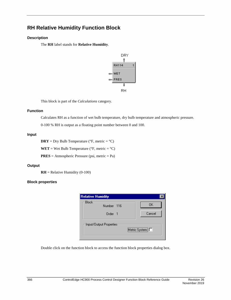
366 ControlEdge HC900 Process Control Designer Function Block Reference Guide Revision 26 November 2019
RH Relative Humidity Function Block
Description The RH label stands for Relative Humidity.
This block is part of the Calculations category.
Function Calculates RH as a function of wet bulb temperature, dry bulb temperature and atmospheric pressure.
0-100 % RH is output as a floating point number between 0 and 100.
Input DRY = Dry Bulb Temperature (°F, metric = °C)
WET = Wet Bulb Temperature (°F, metric = °C)
PRES = Atmospheric Pressure (psi, metric = Pa)
Output RH = Relative Humidity (0-100)
Block properties
Double click on the function block to access the function block properties dialog box.

Revision 26 ControlEdge HC900 Process Control Designer Function Block Reference Guide 367 November 2019
Metric system
Table 97 Metric units
Metric ON OFF
DRY °C °F
WET °C °F
PRES Pa PSI
TIP
It is physically impossible for the wet bulb to be warmer than the dry bulb. If this appears to be the case, it implies a problem with the sensors, and will result in a RH greater than 100 %. Downstream blocks should detect that situation and react promptly.
Example Figure 89 shows an RH function block example.
A setup parameter allows inputs to be in Degrees F or Degrees C. When Degrees F is selected, pressure is assumed to be in PSIA. When Degrees C is selected, pressure is assumed to be in Pa. (101325 Pa = 1 std. Atmosphere.
Figure 89 RH function block example

368 ControlEdge HC900 Process Control Designer Function Block Reference Guide Revision 26 November 2019
ROC Rate of Change Function Block
Description The ROC label stands for Rate of Change.
This block is part of the Auxiliary category.
Function Provides:
• an analog output representing units per minute change of the analog input.
• compare setpoints for high and low rate of change.
• compare selections for increasing, decreasing or both directions of change.
• a logic 1(ON) output when input rate exceeds high rate setpoint
• a logic 1(ON) output when input rate is less than the low rate setpoint.
Inputs IN = Analog Input
Outputs HI_RC = ON if input rate exceeds High Rate setpoint
LO_RC = ON if input rate is less than the Low Rate setpoint
RATE = Analog Output representing Engineering Units per minute of change of the Analog Input
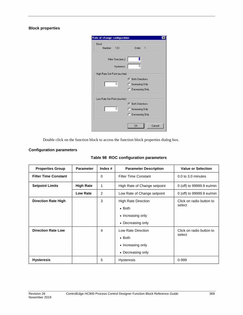
Revision 26 ControlEdge HC900 Process Control Designer Function Block Reference Guide 369 November 2019
Block properties
Double click on the function block to access the function block properties dialog box.
Configuration parameters
Table 98 ROC configuration parameters
Properties Group Parameter Index # Parameter Description Value or Selection
Filter Time Constant 0 Filter Time Constant 0.0 to 3.0 minutes
Setpoint Limits High Rate 1 High Rate of Change setpoint 0 (off) to 99999.9 eu/min
Low Rate 2 Low Rate of Change setpoint 0 (off) to 99999.9 eu/min
Direction Rate High 3 High Rate Direction
• Both
• Increasing only
• Decreasing only
Click on radio button to select
Direction Rate Low 4 Low Rate Direction
• Both
• Increasing only
• Decreasing only
Click on radio button to select
Hysteresis 5 Hysteresis 0-999

370 ControlEdge HC900 Process Control Designer Function Block Reference Guide Revision 26 November 2019
Example Figure 90 illustrates various responses for the Rate Of Change Function Block. You can also use the ROC block to alarm if Rate exceeds the Preset Setpoint Limit.
Figure 90 ROC function block responses
Figure 91 ROC function block example
HI rate SP (INC)
HI RC = ON
HI rate SP (INC)
HI RC = OFF
HI rate SP (DEC)
HI RC = ON
HI rate SP (DEC)
HI RC = OFF
LO rate SP (INC)
LO RC = OFF
LO rate SP (INC)
LO RC = ON
LO rate SP (DEC)
LO RC = OFF
LO rate SP (DEC)
LO RC = ON
High Rate SP (INC ) LOW Rate SP (INC)HI rate SP (INC)
HI RC = OFF
HI rate SP (DEC)
High/Low Rate SP (Both)
LO rate SP (DEC)
High Rate SP (DEC ) LOW Rate SP (DEC)
LO rate SP (INC)
LO RC = OFF
HI rate SP (INC)
HI RC = OFF
HI rate SP (DEC)
LO rate SP (DEC)
LO rate SP (INC)
LO RC = ON
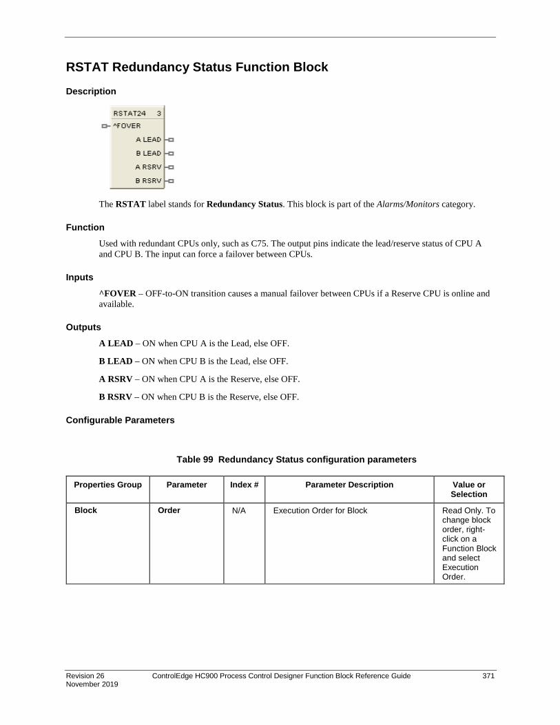
Revision 26 ControlEdge HC900 Process Control Designer Function Block Reference Guide 371 November 2019
RSTAT Redundancy Status Function Block
Description
The RSTAT label stands for Redundancy Status. This block is part of the Alarms/Monitors category.
Function Used with redundant CPUs only, such as C75. The output pins indicate the lead/reserve status of CPU A and CPU B. The input can force a failover between CPUs.
Inputs ^FOVER – OFF-to-ON transition causes a manual failover between CPUs if a Reserve CPU is online and available.
Outputs A LEAD – ON when CPU A is the Lead, else OFF.
B LEAD – ON when CPU B is the Lead, else OFF.
A RSRV – ON when CPU A is the Reserve, else OFF.
B RSRV – ON when CPU B is the Reserve, else OFF.
Configurable Parameters
Table 99 Redundancy Status configuration parameters
Properties Group Parameter Index # Parameter Description Value or Selection
Block Order N/A Execution Order for Block
Read Only. To change block order, right-click on a Function Block and select Execution Order.
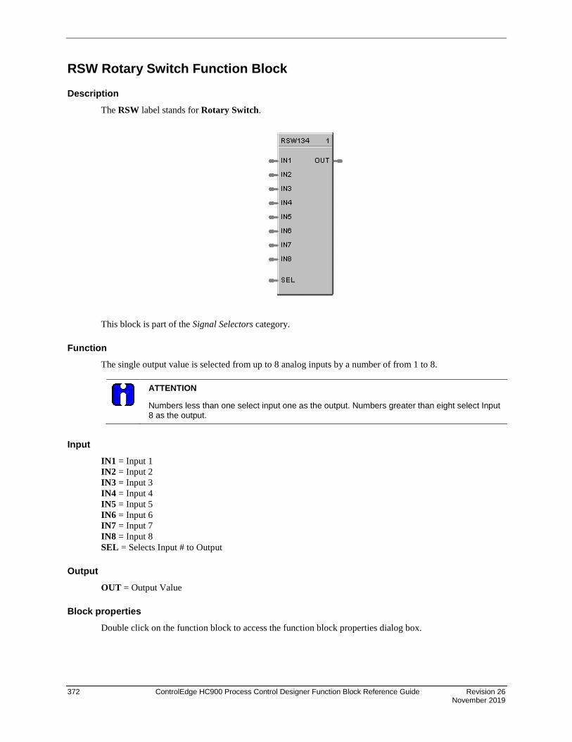
372 ControlEdge HC900 Process Control Designer Function Block Reference Guide Revision 26 November 2019
RSW Rotary Switch Function Block
Description The RSW label stands for Rotary Switch.
This block is part of the Signal Selectors category.
Function The single output value is selected from up to 8 analog inputs by a number of from 1 to 8.
ATTENTION
Numbers less than one select input one as the output. Numbers greater than eight select Input 8 as the output.
Input IN1 = Input 1 IN2 = Input 2 IN3 = Input 3 IN4 = Input 4 IN5 = Input 5 IN6 = Input 6 IN7 = Input 7 IN8 = Input 8 SEL = Selects Input # to Output
Output OUT = Output Value
Block properties Double click on the function block to access the function block properties dialog box.

Revision 26 ControlEdge HC900 Process Control Designer Function Block Reference Guide 373 November 2019
Example Figure 92 shows how a RSW function block works. It selects an output value from up to 8 analog values or number inputs.
Figure 92 RSW function block example
Inputs
Select Input

374 ControlEdge HC900 Process Control Designer Function Block Reference Guide Revision 26 November 2019
RTC Real Time Clock Function Block
Description The RTC label stands for Real Time Clock.
This block is part of the Counters/Timers category.
Function The Real Time Clock block provides outputs pins that you can access in your configuration to make decisions based on the value of the controller’s Real Time Clock value.
The RTC function block has the following dynamic outputs based on the value of the real time clock of the controller:
Seconds, Minutes, Hours, Day of Week, Day of Month, Day of Year, Month, Year.
Example Figure 93 shows a function block diagram using a RTC function block.
Figure 93 RTC function block example
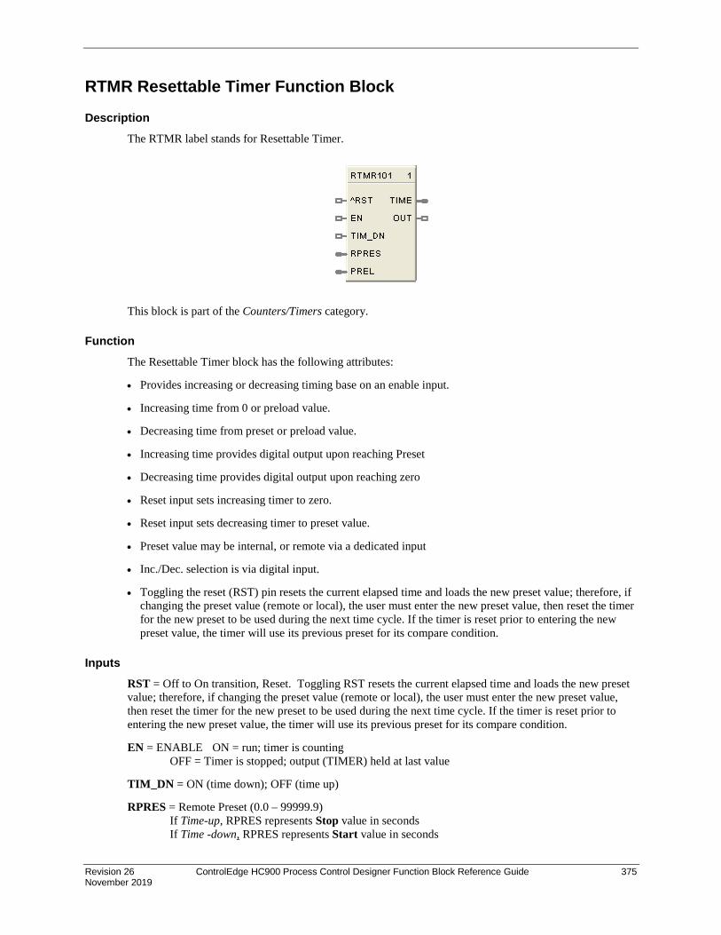
Revision 26 ControlEdge HC900 Process Control Designer Function Block Reference Guide 375 November 2019
RTMR Resettable Timer Function Block
Description The RTMR label stands for Resettable Timer.
This block is part of the Counters/Timers category.
Function The Resettable Timer block has the following attributes:
• Provides increasing or decreasing timing base on an enable input.
• Increasing time from 0 or preload value.
• Decreasing time from preset or preload value.
• Increasing time provides digital output upon reaching Preset
• Decreasing time provides digital output upon reaching zero
• Reset input sets increasing timer to zero.
• Reset input sets decreasing timer to preset value.
• Preset value may be internal, or remote via a dedicated input
• Inc./Dec. selection is via digital input.
• Toggling the reset (RST) pin resets the current elapsed time and loads the new preset value; therefore, if changing the preset value (remote or local), the user must enter the new preset value, then reset the timer for the new preset to be used during the next time cycle. If the timer is reset prior to entering the new preset value, the timer will use its previous preset for its compare condition.
Inputs RST = Off to On transition, Reset. Toggling RST resets the current elapsed time and loads the new preset value; therefore, if changing the preset value (remote or local), the user must enter the new preset value, then reset the timer for the new preset to be used during the next time cycle. If the timer is reset prior to entering the new preset value, the timer will use its previous preset for its compare condition.
EN = ENABLE ON = run; timer is counting OFF = Timer is stopped; output (TIMER) held at last value
TIM_DN = ON (time down); OFF (time up)
RPRES = Remote Preset (0.0 – 99999.9) If Time-up, RPRES represents Stop value in seconds If Time -down, RPRES represents Start value in seconds
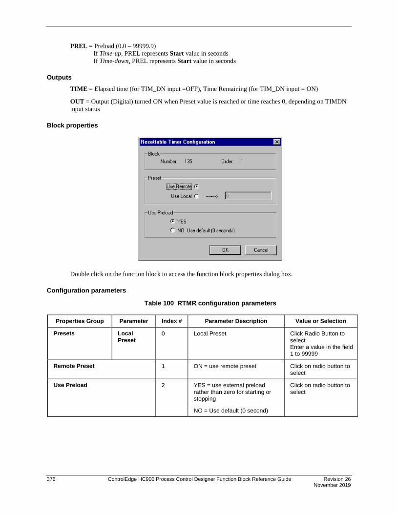
376 ControlEdge HC900 Process Control Designer Function Block Reference Guide Revision 26 November 2019
PREL = Preload (0.0 – 99999.9) If Time-up, PREL represents Start value in seconds If Time-down, PREL represents Start value in seconds
Outputs TIME = Elapsed time (for TIM_DN input =OFF), Time Remaining (for TIM_DN input = ON)
OUT = Output (Digital) turned ON when Preset value is reached or time reaches 0, depending on TIMDN input status
Block properties
Double click on the function block to access the function block properties dialog box.
Configuration parameters
Table 100 RTMR configuration parameters
Properties Group Parameter Index # Parameter Description Value or Selection
Presets Local Preset
0 Local Preset Click Radio Button to select Enter a value in the field 1 to 99999
Remote Preset 1 ON = use remote preset
Click on radio button to select
Use Preload 2 YES = use external preload rather than zero for starting or stopping
NO = Use default (0 second)
Click on radio button to select

Revision 26 ControlEdge HC900 Process Control Designer Function Block Reference Guide 377 November 2019
Timing diagram
Figure 94 Timing diagram for resettable timer
Reset orNewstart
Enable
Timer(If Count-Up)
Timer(If Count-Down)
Out

378 ControlEdge HC900 Process Control Designer Function Block Reference Guide Revision 26 November 2019
RUIO-AI Function Block Description
The RUIO - AI label stands for Redundant Universal IO Analog Input (Supported only with UIO module).
This block is part of the I/O Blocks category.
Function Reads value of an RUIO-Analog Input from a specified real I/O address. Convert analog input value to corresponding output (OUT) in engineering units based on the necessary scaling and conversions performed.
LINEAR - Converts analog input value to corresponding output in units based on a linear 0 % to 100 % scale and specified high and low range values +/-10% over range.
OUT = Scale x Input value + Bias where:
Input value = Analog Value in percent Input
Analog value from specified real I/O address.
^RSTRT = Restart Signal –
When used, a positive (rising) input pulse releases OUT from its failsafe value and FAIL pin from its ON state. Reset to this pin is MUST for clearing this channel fault after repair. This allows for the replacement or repair of the failed AI module or failure condition and operator controlled release.
DIS = disable the RUIO AI channel
Output FAIL = Status of the channel Digital Low (0) = OK Digital High (1) = Both channels (CH-A and CH-B) failed
RDNTFAIL = Status of the channel Digital Low (0) = OK Digital High (1) = Either CH-A or CH-B failed
High range value - Low range value100
Scale =

Revision 26 ControlEdge HC900 Process Control Designer Function Block Reference Guide 379 November 2019
Configuration parameters
Table 101 RUIO-AI configuration parameters
Properties Group
Parameter Index #
Parameter Description Value or Selection
Block Order N/A Execution Order for Block
Read Only.
Address Rack This is the address of the selected Redundant UIO modules rack position (CH-A and CH-B).
Enter a value: from 1 to 12.
I/O Module Address of selected redundant I/O modules (CH-A and CH-B).
Enter a value: from 1 to 12
Channel Channel on selected redundant I/O modules (CH-A and CH-B).
Note: CH-B is Read Only. CH-B value is same as CH-A.
Enter a value: 3 to 16.

380 ControlEdge HC900 Process Control Designer Function Block Reference Guide Revision 26 November 2019
Input Range
Input Range N/A input range 4-20 mA
Range High Range Value
N/A For Linear Inputs Only - output value that corresponds to 100 % input value
For example: Actuation Input = 4-20mA Process variable = Flow Range of Flow = 0 to 250 gal/min High Range Display Value = 250 Low range Display Value = 0 Then 20mA = 250, 4mA = 0
Enter a value:
- 99999 to 99999
Default = 100
Low Range Value
N/A For Linear Inputs Only - output value that corresponds to 0 % input value For example: See "High Range Value"
Enter a value:
- 99999 to 99999
Default = 0
Disable Channel
Output Value 9 The output value when the AI channel is disabled. Disable = ON
Enter a value
Default = 0
Settings Filter Time (sec)
7 A software digital filter is provided for the input designated to smooth the input. You can configure the first order lag time constant from 1 to 120 seconds. 0=no filter
Enter a value:
0 to 120 seconds
Bias 8 Bias is used to compensate the input for drift of an input value due to deterioration of a sensor, or some other cause.
Enter a value:
- 99999 to 99999
Failsafe Failsafe Type 4 Type of Failsafe Use Value - sets the output to the programmed value when failure is detected.
Downscale - Value set at "Low range value" field. Upscale - Value set at "High range value" field.
Line Monitoring
Short circuit Detection
Open Wire Detection
N/A Short circuit detection check enable
Open Wire detection check enable
Read only

Revision 26 ControlEdge HC900 Process Control Designer Function Block Reference Guide 381 November 2019
Example Below diagram shows Function block diagram:
Figure 120 RUIO - AI function block example
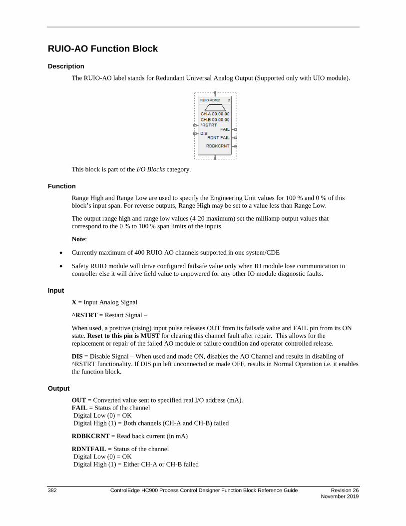
382 ControlEdge HC900 Process Control Designer Function Block Reference Guide Revision 26 November 2019
RUIO-AO Function Block
Description The RUIO-AO label stands for Redundant Universal Analog Output (Supported only with UIO module).
This block is part of the I/O Blocks category.
Function Range High and Range Low are used to specify the Engineering Unit values for 100 % and 0 % of this block’s input span. For reverse outputs, Range High may be set to a value less than Range Low.
The output range high and range low values (4-20 maximum) set the milliamp output values that correspond to the 0 % to 100 % span limits of the inputs.
Note:
• Currently maximum of 400 RUIO AO channels supported in one system/CDE
• Safety RUIO module will drive configured failsafe value only when IO module lose communication to controller else it will drive field value to unpowered for any other IO module diagnostic faults.
Input X = Input Analog Signal
^RSTRT = Restart Signal –
When used, a positive (rising) input pulse releases OUT from its failsafe value and FAIL pin from its ON state. Reset to this pin is MUST for clearing this channel fault after repair. This allows for the replacement or repair of the failed AO module or failure condition and operator controlled release.
DIS = Disable Signal – When used and made ON, disables the AO Channel and results in disabling of ^RSTRT functionality. If DIS pin left unconnected or made OFF, results in Normal Operation i.e. it enables the function block.
Output OUT = Converted value sent to specified real I/O address (mA). FAIL = Status of the channel Digital Low (0) = OK Digital High (1) = Both channels (CH-A and CH-B) failed
RDBKCRNT = Read back current (in mA)
RDNTFAIL = Status of the channel Digital Low (0) = OK Digital High (1) = Either CH-A or CH-B failed
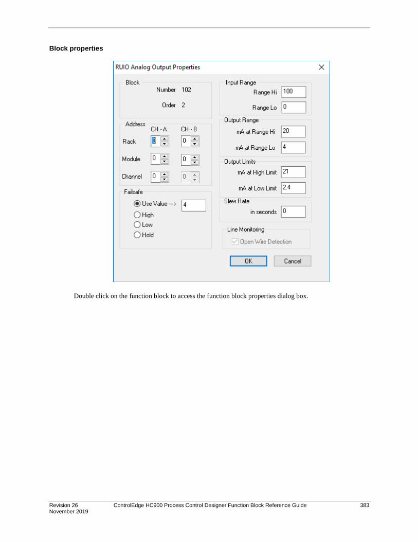
Revision 26 ControlEdge HC900 Process Control Designer Function Block Reference Guide 383 November 2019
Block properties
Double click on the function block to access the function block properties dialog box.

384 ControlEdge HC900 Process Control Designer Function Block Reference Guide Revision 26 November 2019
Configuration parameters
Table 102 Analog output configuration parameters
Parameter Index # Parameter Description Value or Selection
Block Order N/A Execution Order for Block Read Only
Rack Address This is the address of the selected redundant Racks (CH-A and CH-B).
1 to 12
I/O Module Address
Address of selected redundant I/O modules. (CH-A and CH-B).
1 to 12
Channel Address
Channel on selected redundant I/O modules (CH-A and CH-B).
Note: CH-B is Read Only. CH-B value is same as CH-A.
9 to 16
Range Hi 6 High Range Value Engineering Unit - value of input that corresponds to 100 % output value
- 99999 to 99999 Default = 100
Range Low 7 Low Range Value Engineering Unit - value of input that corresponds to 0 % output value
- 99999 to 99999 Default = 0.0
mA at range High
8 Value of mA output that corresponds to 100 % output signal (for example: 20 mA)
3 to 20 Default = 20
mA at Low Range
9 Value of mA output that corresponds to 0 % output signal (for example: 4 mA)
3 to 20 Default = 4
mA at range High Limit
N/A Value of mA that you want to set the High Range Limit
2.4 to 21 Default = 21
mA at Low Range Limit
N/A Value of mA that you want to set the Low Range Limit
2.4 to 21 Default = 2.4
Failsafe Type 4 Type of Failsafe Use Value - sets the output to the programmed value when failure is detected. (2.4 to 21 mA, Default = 4mA)
High - sets the output of the block to the High Output Range Value when failure is detected Low - sets the output of the block to the Low Output Range Value when failure is detected

Revision 26 ControlEdge HC900 Process Control Designer Function Block Reference Guide 385 November 2019
Hold - maintains the last value of the block just prior to the failure being detected Click on Radio Button to select
Slew Rate in seconds
11 Slew Rate is the maximum rate of change required to drive the output from full OFF (0% - typically 4 mA) to full ON (100% - typically 20mA). The block will convert this to a maximum change of the milliamp output per execution cycle of the block.
0.0 to 99
Open Wire Detection
N/A Open Wire detection check enable
Read only
Example Below shows Function Block Diagram using RUIO-AO
Figure 121 RUIO-AO function block example

386 ControlEdge HC900 Process Control Designer Function Block Reference Guide Revision 26 November 2019
RUIO-DI Function Block
Description The RUIO-DI label stands for Redundant Universal IO Digital Input (Supported only with UIO module).
This block is part of the I/O Blocks categories.
Function Provides the digital status of a digital input point and provides interface to other algorithms and functions. The output status may be inverted.
If Digital Point is ON, then OUT = ON
Input ^RSTRT = Restart Signal –
When used, a positive (rising) input pulse releases OUT from its failsafe value and FAIL pin from its ON state. Reset to this pin is MUST for clearing this channel fault after repair. This allows for the replacement or repair of the failed AO module or failure condition and operator controlled release.
DIS = disable the RUIO DI channel
Output OUT = Digital Signal
FAIL = Status of the channel Digital Low (0) = OK Digital High (1) = Both channels (CH-A and CH-B) failed
RDNTFAIL = Status of the channel Digital Low (0) = OK Digital High (1) = Either CH-A or CH-B failed
Block properties
Double click on the function block to access the function block properties dialog box.

Revision 26 ControlEdge HC900 Process Control Designer Function Block Reference Guide 387 November 2019
Configuration parameters
Table 103 RUIO Digital input configuration parameters
Parameter Index # Parameter Description Value or Selection
Rack Address N/A This is the address of the selected redundant Racks (CH-A and CH-B).
From 1 to 12
I/O Module Address
0 Address of selected redundant I/O modules (CH-A and CH-B).
From 1 to 12
Channel Address N/A Channel on selected redundant I/O modules (CH-A and CH-B).
Note: CH-B is Read Only. CH-B value is same as CH-A.
From 3 to 16,
Failsafe Type 4 Type of Failsafe ON - set the output of the block to ON when failure is detected OFF - set the output of the block to OFF when failure is detected Hold - maintains the last value of the block just prior to the failure being detected
Invert 5 If INVERT is selected, OUT = inverse of physical input. The slash will be present in the CONTACT symbol only when the invert box is selected on the dialog box.
Short circuit Detection
Open Wire Detection
N/A Short circuit detection check enable Open Wire detection check enable
Click on Radio to select or deselect
Example
Figure 122 shows a Function Block Diagram using a RUIO-DI function block.
Figure 122 RUIO-DI function block example

388 ControlEdge HC900 Process Control Designer Function Block Reference Guide Revision 26 November 2019
RUIO-DO Function Block
Description The RUIO-DO label stands for Redundant Universal Digital Output (Supported only with UIO module).
This block is part of the I/O Blocks categories.
Function Provides a digital status from the algorithms and functions to a physical logic output. The output status may be inverted.
Note: • Safety RUIO module will drive configured failsafe value only when IO module lose
communication to controller else it will drive field value to unpowered for any other IO module diagnostic faults.
• It is required to reset DO channel to resume from failsafe state for new DO block after hotstart • In the openwire condition, performing reset on RUIO DO, channel status become healthy for 9 sec
and then detects the openwire. During this period output changes as per the input.
Input X = Input Status Signal
^RSTRT = Restart Signal – When used, a positive (rising) input pulse releases OUT from its failsafe value and FAIL pin from its ON state. Reset to this pin is MUST for clearing this channel fault after repair. This allows for the replacement or repair of the failed DO module or failure condition and operator controlled release.
DIS = Disable Signal – When used and made ON, disables the DO Channel and results in disabling of ^RSTRT functionality. If DIS pin left unconnected or made OFF, results in Normal Operation i.e. it enables the function block
Output OUT = Physical Output Value
RDBKCRNT = Read back current (in mA). This values will have deviation of 1 to 20mA as field current goes high.
FAIL = Status of the channel Digital Low (0) = OK Digital High (1) = Both channels (CH-A and CH-B) failed
RDNTFAIL = Status of the channel Digital Low (0) = OK Digital High (1) = Either CH-A or CH-B failed

Revision 26 ControlEdge HC900 Process Control Designer Function Block Reference Guide 389 November 2019
Block properties
Double click on the function block to access the function block properties dialog box.
Table 104: Configurable Parameters RUIO DO
Parameter
Parameter Description Value or Selection
Rack Address N/A This is the address of the selected redundant Racks (CH-A and CH-B).
From 1 to 12
I/O Module Address
0 Address of selected redundant I/O modules (CH-A and CH-B).
From 1 to 12
Channel Address
N/A Channel on selected redundant I/O modules (CH-A and CH-B).
Note: CH-B is Read Only. CH-B value is same as CH-A.
From 3 to 16.
Failsafe Type 4 Type of Failsafe ON - set the output of the block to ON when failure is detected OFF - set the output of the block to OFF when failure is detected Hold - maintains the last value of the block just prior to the failure being detected
Invert 5 If INVERT is selected, OUT = inverse of physical input. The slash will be present in the CONTACT symbol only when the invert box is selected on the dialog box.

390 ControlEdge HC900 Process Control Designer Function Block Reference Guide Revision 26 November 2019
Short circuit Detection
Open Wire Detection
N/A Short circuit detection check
enable Open Wire detection check
enable
Read only
Example Figure 123 shows a Function Block Diagram using a RUIO-DO function block.
Figure 123 RUIO-DO function block example

Revision 26 ControlEdge HC900 Process Control Designer Function Block Reference Guide 391 November 2019
SAFPDE Safety Peer Monitor Function Block
Description
The SAFPDE label is short-hand for the Safety Peer Monitor block.
This block is a member of the Communications category and is only available on SIL devices, such as the C30S, C50S, C70S, and C75S using version 6.3xx and above.
Function
The Safety Peer Monitor block functions similar to the Peer Comm (PDE) block. It is a communication function block that allows interconnecting controllers with Ethernet media and networking devices to communicate with each other.
This allows controller to monitor the safety peer communication status with peer controller. SAFPDE block is required for safety peer communication to work. Also, it is recommended to have failsafe timeout (in block configuration properties) of 5 times the publisher or subscriber Normal Cycle time whichever is higher.
Inputs
DIS = DIS pin disables the communication between the two controllers and NO_SCAN pin will become ON.
RST = RST resets the communication with peer controller selected in the Safety Peer Monitor block
Outputs
NO_SCAN – ON = device has not received updates from peer within the time defined by the failsafe time selected within the block properties. OFF = device is receiving updates from peer.
NO_CONN – ON = cannot connect to peer device. OFF = good connection, Peer found.
Block Properties
Double click on the function block to access the function block properties.

392 ControlEdge HC900 Process Control Designer Function Block Reference Guide Revision 26 November 2019
Configuration Parameters When the properties page is opened after adding the Safety Peer Monitor block to the configuration, the user will be prompted to select the ‘.xml’ from the configuration that corresponds to the controller they would like to monitor. The image below shows what the user will see when opening a Safety Peer Monitor block that has yet to be configured:
After selecting the XML that corresponds with the configuration the user wants, the Peer Name field will be populated, as shown below:
The default ‘Failsafe Timeout’ is set to 3 seconds. The user can choose a new timeout in seconds or franctions of seconds rabged from 1 to 30 seconds, and then press ‘OK’. This failsafe timeout applies to NO_SCAN PIN status of the controller shown in ‘Peer Name’.

Revision 26 ControlEdge HC900 Process Control Designer Function Block Reference Guide 393 November 2019
Parameter Index # Parameter Description
Value Or Selection Default
Peer Name N/A Name of the Peer Controller for this block
Selected thru the xml file selection
NA
Failsafe Timeout N/A Failsafe Timeout in seconds or fractions of seconds
Enter between 1.0 to 30.0
3 sec
Failsafe Action N/A Action to be taken when the failsafe timeout occurs.
No Latch – NO_SCAN status will get reset(OFF) once the peer communication resumes
Latch – NO_SCAN remain ON (latched) even after the peer communication resumes until reset (RST) given
Click on radio button to select
Latch
Related Function Blocks - ANAIMP – Safety Analog Import block
- DIGIMP – Safety Digital Import block

394 ControlEdge HC900 Process Control Designer Function Block Reference Guide Revision 26 November 2019
Example:
Figure 95 SAFPDE function block examples
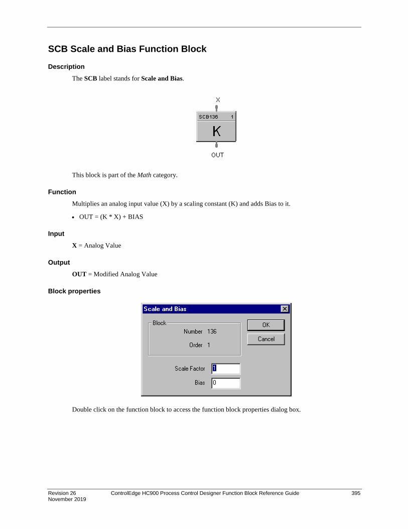
Revision 26 ControlEdge HC900 Process Control Designer Function Block Reference Guide 395 November 2019
SCB Scale and Bias Function Block
Description The SCB label stands for Scale and Bias.
This block is part of the Math category.
Function Multiplies an analog input value (X) by a scaling constant (K) and adds Bias to it.
• OUT = (K * X) + BIAS
Input X = Analog Value
Output OUT = Modified Analog Value
Block properties
Double click on the function block to access the function block properties dialog box.

396 ControlEdge HC900 Process Control Designer Function Block Reference Guide Revision 26 November 2019
Configuration parameters
Table 105 SCB configuration parameters
Properties Group Parameter Index # Parameter Description Value or Selection
Scale Factor 0 K - Multiplier (scaling) constant –99999 to 99999
Bias 1 Bias Constant - is used to compensate the input for drift of an input value due to deterioration of a sensor, or constant offset to an input.
–99999 to 99999
Example Figure 96 shows function block diagrams using a SCB function block.
Figure 96 SCB function block examples

Revision 26 ControlEdge HC900 Process Control Designer Function Block Reference Guide 397 November 2019
SEQ Sequencer Function Block
Description The SEQ label stands for Sequencer.
This block is part of the Fast Logic categories.
Function Each sequencer supports up to 16 digital outputs that may be either on or off in each of 50 states e.g. PURGE, FILL, HEAT, etc, per block The sequencer may have up to 64 sequential steps that activate within the states of the process.
Steps of the sequencer may be configured to advance based on time, on digital event (2 per step), or a manual advance. A separate jog function is also provided.
The function can also configure an analog output on a step basis. The operational sequence for the steps is retained in a separate sequence file in the memory of the controller that may be selected on-demand through a user interface or via a recipe.
Up to 20 sequences may be stored.

398 ControlEdge HC900 Process Control Designer Function Block Reference Guide Revision 26 November 2019
Inputs ENA = Level input to enable the block - only checked in Ready State; input is ignored if not connected.
NSEQ = Sequence Number. See ATTENTION below.
NSTEP = Starting Step Number. See ATTENTION below.
^SET = Pulse input to load NSEQ and NSTEP numbers. See ATTENTION below.
^JOG = Pulse input to jog to step number
^RESET = Pulse input for reset
HOLD = Input for Hold (level trigger)
^RUN = Edge triggered input for run
^ADV = Edge triggered input to advance to the next step defined in the current sequence step
ATTENTION
If either or both NSEQ and NSTEP are connected directly to analog variables, when that analog variable changes (for example: via a recipe load), then the Sequencer block will immediately use the new value internally.
If NSEQ or NSTEP is connected to any other function type then their values are loaded into the Sequencer only when ^SET goes through a positive transition.
Outputs OUT1 thru OUT16 = State Output values
STMR = Time remaining in current step (minutes)
MODE = Sequence Mode [N/A, RESET, RUN, HOLD, STOP]
STATE = Current State number (Output states as configured by the user)
AUX = Auxiliary Output corresponding to the current step
STEP = Current Step number
Configurable Parameters The Sequencer properties dialog box is divided into 3 tab cards

Revision 26 ControlEdge HC900 Process Control Designer Function Block Reference Guide 399 November 2019
General tab
Parameter Index # Parameter Description Value or Selection
Tag Name 0 Tag Name of Sequencer 16 characters maximum (ASCII characters only)
Descriptor Description of Sequence 16 characters maximum (ASCII characters only)
Aux label Auxiliary Output label for OI Display
8 characters maximum
Aux Units Auxiliary Output Engineering Units for OI Display
4 Characters maximum
Aux Decimal Places
Decimal Places for Auxiliary Output Value
0-3
Labels tab
Parameter Index # Parameter Description Value or Selection
Out1 thru Out16
0 Output Labels for OI Display 8 characters maximum
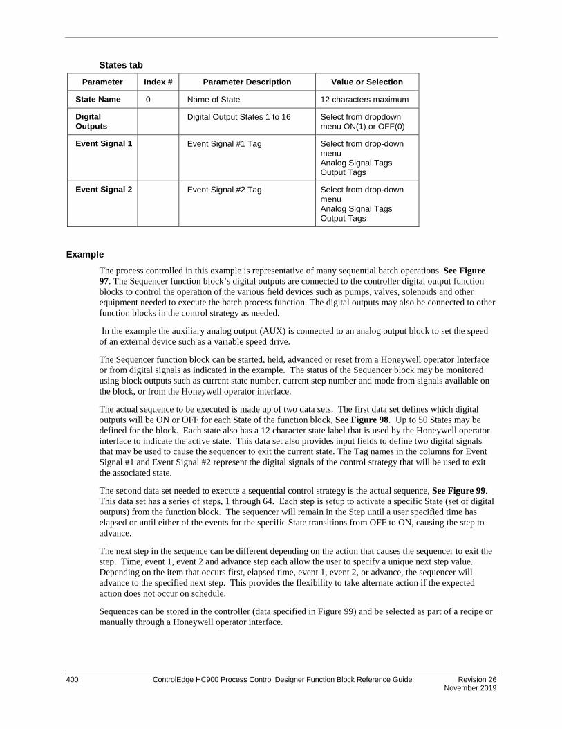
400 ControlEdge HC900 Process Control Designer Function Block Reference Guide Revision 26 November 2019
States tab
Parameter Index # Parameter Description Value or Selection
State Name 0 Name of State 12 characters maximum
Digital Outputs
Digital Output States 1 to 16 Select from dropdown menu ON(1) or OFF(0)
Event Signal 1 Event Signal #1 Tag Select from drop-down menu Analog Signal Tags Output Tags
Event Signal 2 Event Signal #2 Tag Select from drop-down menu Analog Signal Tags Output Tags
Example The process controlled in this example is representative of many sequential batch operations. See Figure 97. The Sequencer function block’s digital outputs are connected to the controller digital output function blocks to control the operation of the various field devices such as pumps, valves, solenoids and other equipment needed to execute the batch process function. The digital outputs may also be connected to other function blocks in the control strategy as needed.
In the example the auxiliary analog output (AUX) is connected to an analog output block to set the speed of an external device such as a variable speed drive.
The Sequencer function block can be started, held, advanced or reset from a Honeywell operator Interface or from digital signals as indicated in the example. The status of the Sequencer block may be monitored using block outputs such as current state number, current step number and mode from signals available on the block, or from the Honeywell operator interface.
The actual sequence to be executed is made up of two data sets. The first data set defines which digital outputs will be ON or OFF for each State of the function block, See Figure 98. Up to 50 States may be defined for the block. Each state also has a 12 character state label that is used by the Honeywell operator interface to indicate the active state. This data set also provides input fields to define two digital signals that may be used to cause the sequencer to exit the current state. The Tag names in the columns for Event Signal #1 and Event Signal #2 represent the digital signals of the control strategy that will be used to exit the associated state.
The second data set needed to execute a sequential control strategy is the actual sequence, See Figure 99. This data set has a series of steps, 1 through 64. Each step is setup to activate a specific State (set of digital outputs) from the function block. The sequencer will remain in the Step until a user specified time has elapsed or until either of the events for the specific State transitions from OFF to ON, causing the step to advance.
The next step in the sequence can be different depending on the action that causes the sequencer to exit the step. Time, event 1, event 2 and advance step each allow the user to specify a unique next step value. Depending on the item that occurs first, elapsed time, event 1, event 2, or advance, the sequencer will advance to the specified next step. This provides the flexibility to take alternate action if the expected action does not occur on schedule.
Sequences can be stored in the controller (data specified in Figure 99) and be selected as part of a recipe or manually through a Honeywell operator interface.

Revision 26 ControlEdge HC900 Process Control Designer Function Block Reference Guide 401 November 2019
Figure 97 Sequencer function block example - Part 1
Figure 98 Sequencer function block example - Part 2

402 ControlEdge HC900 Process Control Designer Function Block Reference Guide Revision 26 November 2019
Figure 99 Sequencer function block example - Part 3

Revision 26 ControlEdge HC900 Process Control Designer Function Block Reference Guide 403 November 2019
SPEV Setpoint Programming Event Decoder Function Block
Description The SPEV label stands for Setpoint Programming Events.
This block is part of the Setpoint Program and Setpoint Scheduler categories.
Function Sets up to sixteen digital event outputs that may be ON or OFF on a per segment basis. Inputs include program number, segment number, and program state (READY, RUN, HOLD, GHOLD, STOP) from setpoint program block or setpoint scheduler block.
• If Program Number (PGM) = 0, Segment Number (SEG) = 0, or Program State (STA) is RESET; then: E1 to E16 = OFF.
• Otherwise, E1 to E16 = as specified in program (PGM), segment (SEG).
Inputs PGM = Profile number For SP Programmer - 99 For SP Scheduler - 20 SEG = Segment number (1 to 50). STA = Program/schedule State (Ready, Run, Hold, Ghold, Stop).

404 ControlEdge HC900 Process Control Designer Function Block Reference Guide Revision 26 November 2019
ATTENTION
SPEV inputs must be connected directly to corresponding outputs of SPP (Setpoint Program) or SPS (Setpoint Scheduler) block. In Stop state, events stay in the state defined in the last segment.
Outputs E1 = Digital signal - segment event 1 E2 = Digital signal - segment event 2 E3 = Digital signal - segment event 3 E4 = Digital signal - segment event 4 E5 = Digital signal - segment event 5 E6 = Digital signal - segment event 6 E7 = Digital signal - segment event 7 E8 = Digital signal - segment event 8 E9 = Digital signal - segment event 9 E10 = Digital signal - segment event 10 E11 = Digital signal - segment event 11 E12 = Digital signal - segment event 12 E13 = Digital signal - segment event 13 E14 = Digital signal - segment event 14 E15 = Digital signal - segment event 15 E16 = Digital signal - segment event 16
Block properties Double click on the function block to access the function block properties dialog box.

Revision 26 ControlEdge HC900 Process Control Designer Function Block Reference Guide 405 November 2019
Example Figure 100 shows a function block diagram using a SPEV function block to provide event outputs for a setpoint programmer.
Figure 100 SPEV function block example
The SP programmer event output status may be directed todigital outputs, part of control logic, or be directed to signaltags for use anywhere within the control configuration.
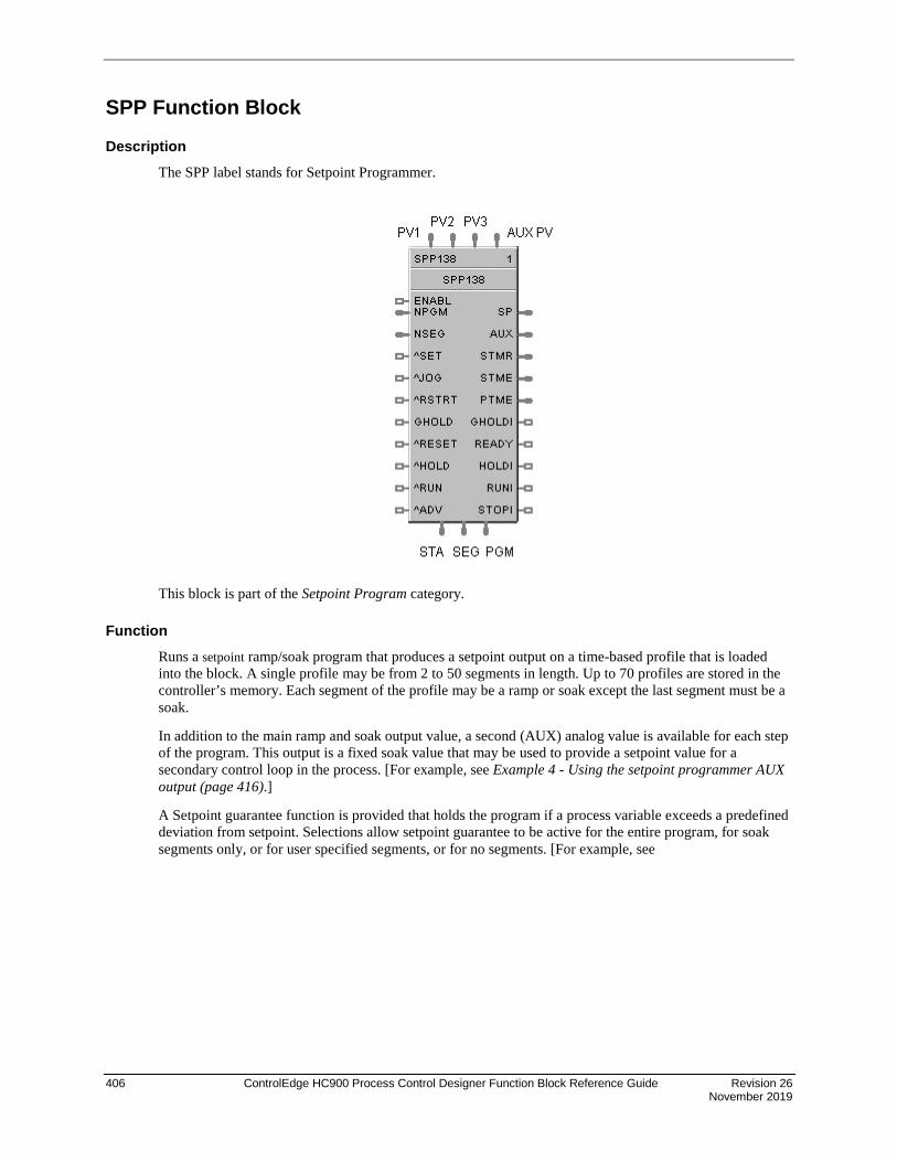
406 ControlEdge HC900 Process Control Designer Function Block Reference Guide Revision 26 November 2019
SPP Function Block
Description The SPP label stands for Setpoint Programmer.
This block is part of the Setpoint Program category.
Function Runs a setpoint ramp/soak program that produces a setpoint output on a time-based profile that is loaded into the block. A single profile may be from 2 to 50 segments in length. Up to 70 profiles are stored in the controller’s memory. Each segment of the profile may be a ramp or soak except the last segment must be a soak.
In addition to the main ramp and soak output value, a second (AUX) analog value is available for each step of the program. This output is a fixed soak value that may be used to provide a setpoint value for a secondary control loop in the process. [For example, see Example 4 - Using the setpoint programmer AUX output (page 416).]
A Setpoint guarantee function is provided that holds the program if a process variable exceeds a predefined deviation from setpoint. Selections allow setpoint guarantee to be active for the entire program, for soak segments only, or for user specified segments, or for no segments. [For example, see

Revision 26 ControlEdge HC900 Process Control Designer Function Block Reference Guide 407 November 2019
Example 1 - PID with setpoint programmer and guaranteed soak (page 413).]
Up to 3 Process Variables may be configured as inputs to the block for setpoint guarantee.

408 ControlEdge HC900 Process Control Designer Function Block Reference Guide Revision 26 November 2019
Input PV1 = Process Variable #1 value in engineering units, for deviation check.
PV2 = Process Variable #2 value in engineering units, for deviation check.
PV3 = Process Variable #3 value in engineering units, for deviation check.
Aux PV = Aux PV for Aux PV Display.
ENABL = Level input to enable the block - only checked in Ready State; input is ignored if not connected.
NPGM = New profile number (1 to 70). See ATTENTION below.
NSEG = New start segment number (1 to 99). When connected, it is used in conjunction with the SET input of the block to set the current segment of the profile to the value of NSEG. See ATTENTION below.
^SET = Pulse input to load NPGM and NSEG numbers. See ATTENTION below.
^JOG = Pulse input to Jog to a predefined segment.
RSTRT = Pulse input for restart action after power interruption [For example, see

Revision 26 ControlEdge HC900 Process Control Designer Function Block Reference Guide 409 November 2019
Example 5 - Controlled Restart after Power Loss (page 417).]
GHOLD = Guaranteed soak hold - changes program state from RUN to GHOLD when turned ON and GHOLD to run when OFF.
^RESET = Pulse input RESETS program, when turned ON.*
^HOLD = Pulse input puts program in HOLD, when turned ON. Run needed to restart.
^RUN = Pulse input puts program in RUN, when turned ON; except when program is in GHOLD state.
^ADV = Pulse Input for advance of segment.
*For example, see Example 3 - Alternate methods for actuating SP programmer START/HOLD/RESET functions (page 415).
ATTENTION
If either or both NPGM and NSEG are connected directly to analog variables, when that analog variable changes (for example: via a recipe load), then the Setpoint Programmer block will immediately use the new value internally.
If NPGM or NSEG is connected to any other function type then their values are loaded into the SP Programmer only when ^SET goes through a positive transition.
Output SP = Programmed setpoint value in engineering units
AUX = Second non-ramping auxiliary setpoint output in engineering units. [For example, see Example 4 - Using the setpoint programmer AUX output (page 416).]
STMR = Time Remaining in current segment - in minutes.
STME = Time Elapsed in current segment - in minutes.
PTME = Time Elapsed in program - in minutes
GHOLDI = Guaranteed soak hold indication - turns on if PV is outside guaranteed soak band and Guaranteed Soak is enabled.
READY = Program Reset state indication
HOLDI = Program Hold state indication
RUNI = Program Run state indication
STOPI = Program Stop indication (Program Complete)
PGM = Current Profile Number (1 to 99) - connect to PGM input on SPEV block.
SEG = Current Segment Number (1 to 50) - connect to SEG input on SPEV block.
STA = Current program state (RESET, HOLD, RUN, GHOLD, STOP). Connected to STA input of the SPEV block
ATTENTION
The program states are:
• 0 = Until block is first executed after power up

410 ControlEdge HC900 Process Control Designer Function Block Reference Guide Revision 26 November 2019
• 1 = Reset
• 2 = Run
• 3 = Hold
• 4 = GHold
• 5 = Stop
• 6 = Disabled
TIP
• If the first step of a profile is a ramp, the program will start the ramp from the value of PV Input 1. If the first step of a profile is a soak, the program will start from the soak value. If consistent starting values are required, begin all profiles with a soak.
• The PV inputs are used to determine PV–SP deviation for guaranteed soak segments.
• Valid program numbers begin with 1. Valid segment numbers begin with 1.
• The GHOLD output is not affected by the status of the GHOLD input.
• The RST, HLD, RUN, JOG, ADV, SET, RESTART inputs are activated only when the respective input changes from OFF to ON. A maintained ON input has no different affect than a pulsed ON input (that is, it has no effect until it turns OFF and then back ON again).
• The program may be changed (with some exceptions) from the current state to a new state by the operator as well as by inputs to the SPP block. Table 106 lists the resulting states.
• Concerning changing program state, if more than one function block input is on in the same execution cycle, RESET has priority over HOLD and RUN, and GHOLD has priority over RUN.
• Also, function block inputs will override inputs from the Operator Panel that occur during the same execution cycle. And finally, state changes from the Operator Panel are processed on the basis of the “last change wins.”
• At the beginning of a segment, STME will be 0 for one execution cycle to permit start of segment detection by other blocks.
• At the end of a segment, STMR will be 0 for one execution cycle to permit end of segment detection by other blocks.
• If RESTART is On, the block will use PV1 as a starting value and ramp at Restart Rate back to the last SP value, then complete the remaining portion of the segment. Restart Rate is a property of the profile (program)
• “Fastforward” (i.e. Verify) is initiated through the operator interface. It is not an input pin. Fastforward is a way to check for proper functioning of the profile’s events and outputs, without having to wait for the profile to execute at its normal speed. When FASTFORWARD is ON, the program will run at a speed 60 times faster. When FASTFORWARD is OFF, the program will run at normal speed.
• You must end with a Soak segment.
• Events remain in their last configured state at program end.
• A Reset will place the SPP in Ready mode and Reset all Event outputs.
• If Restart pin is connected, must enter a value into Profile Restart Rate. If left = 0 profile will not proceed.
Table 106 SPP inputs and current state

Revision 26 ControlEdge HC900 Process Control Designer Function Block Reference Guide 411 November 2019
Input Current State
RESET HOLD RUN GHOLD STOP
RESET RESET RESET RUN RESET RESET
HOLD HOLD HOLD HOLD HOLD STOP
RUN RUN RUN RUN GHOLD STOP
GHOLD RESET HOLD GHOLD GHOLD STOP
Restart scenario options
Table 107 Restart scenario options
1 No Action taken Program will start at the point where it was prior to power down.
2 Use the Restart feature of the Setpoint Programmer with a configurable Ramp Rate.
This feature will use the PV (connected to PV1) as the initial starting point for the Setpoint and will use a configurable ramp rate for the profile. When the temperature gets to the original Setpoint prior to power down, the program will continue. See Figure 105, Scenario A.
3 Use the Restart feature of the Setpoint Programmer with a configurable Ramp Rate and use a compare function so that the restart will apply only after a certain time.
You may gate this Restart input to the programmer to only apply after a certain time off and/or a certain segment if desired using Compare function blocks. See Figure 105, Scenario B.
ATTENTION
Be sure to configure the Restart Ramp Rate when a controlled restart is being configured. If not the default value of 0 will cause the programmer to freeze.

412 ControlEdge HC900 Process Control Designer Function Block Reference Guide Revision 26 November 2019
Block properties
Double click on the function block to access the function block properties dialog box.
Configuration parameters
Table 108 SPP configuration parameters
Properties Group Parameter Index # Parameter Description Value or Selection
Block Tag Name N/A 16 character tag name (ASCII characters only)
Descriptor N/A Block descriptor
Display Decimal Places
N/A Number of places to display after the decimal point
0-5
SP Units N/A Engineering unit descriptor 6 characters
Aux Decimal Places
N/A Number of places to display after the decimal point
4 Characters
Failsafe SP Failsafe Setpoint
0 Failsafe Setpoint Value –9999 to 9999 Engineering Units

Revision 26 ControlEdge HC900 Process Control Designer Function Block Reference Guide 413 November 2019
Example 1 - PID with setpoint programmer and guaranteed soak
Figure 101 PID with setpoint programmer and guaranteed soak

414 ControlEdge HC900 Process Control Designer Function Block Reference Guide Revision 26 November 2019
Example 2 - PID with setpoint programmer and event outputs
Figure 102 PID with setpoint programmer and event outputs
The SP programmer event output status may be directed todigital outputs, part of control logic, or be directed to signaltags for use anywhere within the control configuration.
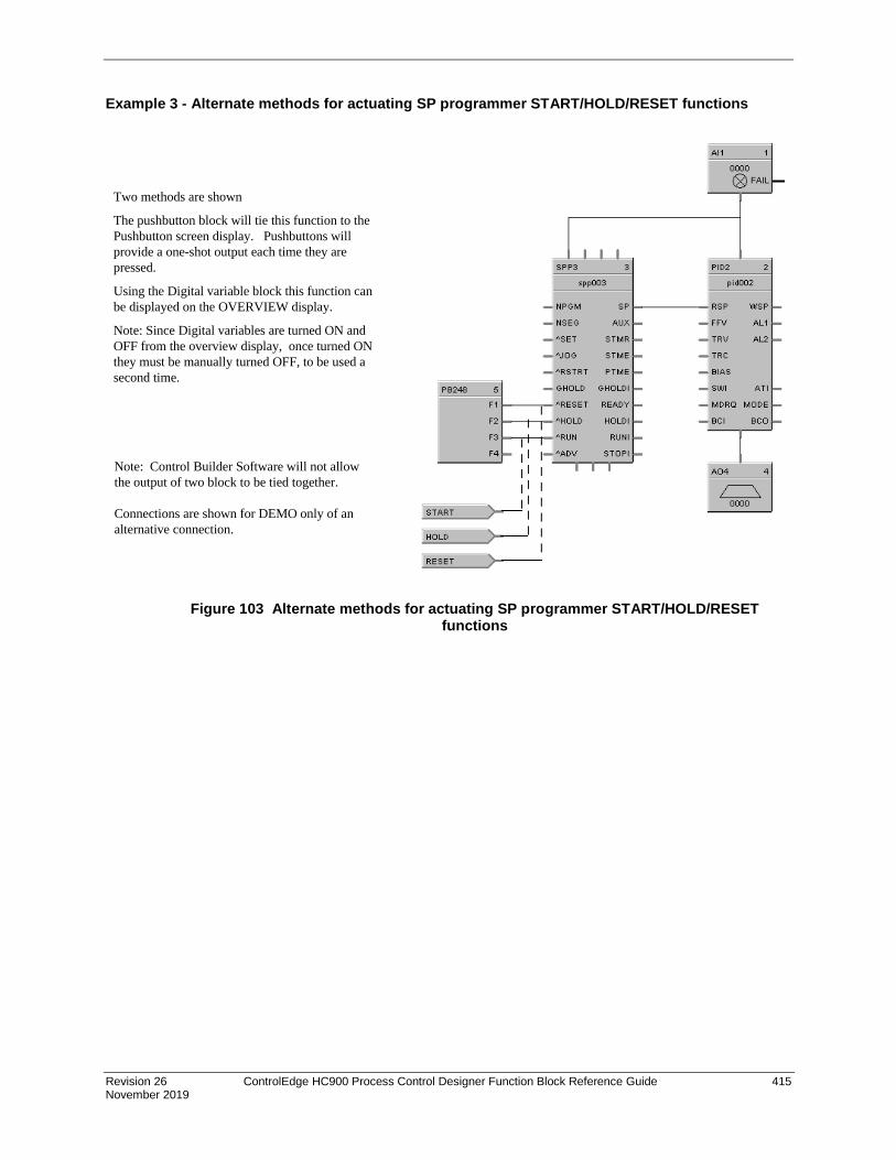
Revision 26 ControlEdge HC900 Process Control Designer Function Block Reference Guide 415 November 2019
Example 3 - Alternate methods for actuating SP programmer START/HOLD/RESET functions
Figure 103 Alternate methods for actuating SP programmer START/HOLD/RESET functions
Two methods are shown
The pushbutton block will tie this function to thePushbutton screen display. Pushbuttons willprovide a one-shot output each time they arepressed.
Using the Digital variable block this function canbe displayed on the OVERVIEW display.
Note: Since Digital variables are turned ON andOFF from the overview display, once turned ONthey must be manually turned OFF, to be used asecond time.
Note: Control Builder Software will not allowthe output of two block to be tied together.
Connections are shown for DEMO only of analternative connection.
FAIL

416 ControlEdge HC900 Process Control Designer Function Block Reference Guide Revision 26 November 2019
Example 4 - Using the setpoint programmer AUX output
Figure 104 Using the setpoint programmer AUX output

Revision 26 ControlEdge HC900 Process Control Designer Function Block Reference Guide 417 November 2019
Example 5 - Controlled Restart after Power Loss SCENARIO A
SCENARIO B
Figure 105 Controlled restart after power loss

418 ControlEdge HC900 Process Control Designer Function Block Reference Guide Revision 26 November 2019
SPS Setpoint Scheduler Function Block
Description The SPS label stands for Master Setpoint Scheduler.
This block is part of the Setpoint Scheduler category.
Overview
The objective of the Setpoint scheduler is to provide a sequence of multiple setpoint outputs (both analog and digital) which are referenced to a common time base. Five setpoint schedule block types will be implemented:
Master Setpoint Scheduler Block (SPS)
Auxiliary Setpoint Block (SPSA)
Digital Event Block (SPEV)
State Switch Block (STSW)
State Flags Block (STFL)
A suite of Setpoint Scheduler blocks is comprised of one master Setpoint Block (required) and optionally, one Digital Event, one Auxiliary Setpoint, one State Switch, and/or one State Flags block.
SPS Block Function
The Master (SPS) block supports up to 8 ramp or soak outputs operating on a common time base. It accepts one PV for each setpoint. Setpoint guarantee is provided for the master (SPS) block setpoints with a single symmetrical value for each setpoint output. You can assign a failsafe value for each setpoint.

Revision 26 ControlEdge HC900 Process Control Designer Function Block Reference Guide 419 November 2019
Inputs ENABL=Level input to enable the block. Only checked in ready state. Input is ignored if not connected.
NPGM = Program Number (when SET is ON). See ATTENTION below.
NSEG = Starting Segment Number (when SET is ON). See ATTENTION below.
^SET = Pulse Input to load NPGM and SEG numbers. See ATTENTION below.
PV1 = 1st Process Variable
PV2 = 2nd Process Variable
PV3 = 3rd Process Variable
PV4 = 4th Process Variable
PV5 = 5th Process Variable
PV6 = 6th Process Variable
PV7 = 7th Process Variable
PV8 = 8th Process Variable
STRQ = for connection to the STQR output of the STSW function block. (See Figure 106.) The STSW block encodes discrete inputs to a form that will convey change mode requests from the STSW block: 0.0 No Change 1.0 Jog State 2.0 Guaranteed Hold State 4.0 Reset State 8.0 Hold State 16.0 Run State 32.0 Advance state
ATTENTION
If either or both NPGM and NSEG are connected directly to analog variables, when that analog variable changes (for example: via a recipe load), then the Setpoint Scheduler block will immediately use the new value internally.
If NPGM or NSEG is connected to any other function type then their values are loaded into the SP Scheduler only when ^SET goes through a positive transition.
Outputs PGM = Current Program Number SEG = Current Segment number STA = Program State (Reset, Run, Hold, Ghold, Stop). SP1 = Setpoint #1 Output (EU) SP2 = Setpoint #2 Output (EU) SP3 = Setpoint #3 Output (EU) SP4 = Setpoint #4 Output (EU) SP5 = Setpoint #5 Output (EU) SP6 = Setpoint #6 Output (EU) SP7 = Setpoint #7 Output (EU) SP8 = Setpoint #8 Output (EU)

420 ControlEdge HC900 Process Control Designer Function Block Reference Guide Revision 26 November 2019
Block properties Double click on the function block to access the function block properties dialog box.
Dialog box structure The SPS properties dialog box is divided into four tab cards
TAG/FAILSAFE MAIN OUTPUT LABELS AUXILIARY OUTPUT LABELS EVENT LABELS
Click on the tab to access the properties for that tab.
TAG/FAILSAFE tab
Double click on the function block to access the function block properties dialog box.
Table 109 Tag/Failsafe configuration parameters
Properties Group Parameter Index # Parameter Description Value or Selection
Block Tag Name N/A 16 character tag name (ASCII characters only)
Descriptor N/A Block descriptor
Failsafe Setpoints SP 0 thru 8 0 Failsafe Setpoint 1 thru 8 Failsafe Value is the initial value when exiting the program mode. Default Failsafe value is 0.0.
Value in EU

Revision 26 ControlEdge HC900 Process Control Designer Function Block Reference Guide 421 November 2019
MAIN OUTPUT LABELS tab It lets you set up labels for Main Outputs in the Setpoint Schedule to be displayed on the Operator Interface. Enter Label names, Units(eu), and Decimal places
Table 110 describes the parameters and the value or selection.
Double click on the function block to access the function block properties dialog box.
Table 110 Main Output labels configuration parameters
Parameter Index # Parameter Description Value or Selection
SP
SP1 thru SP8
Label N/A Label name for Operator Interface 8 characters max.
Units N/A Units for Operator Interface 4 characters max.
Decimal Places
N/A Decimal places for operator Interface
0 - 4
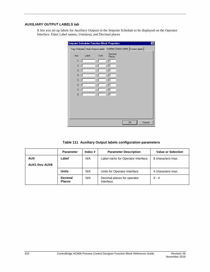
422 ControlEdge HC900 Process Control Designer Function Block Reference Guide Revision 26 November 2019
AUXILIARY OUTPUT LABELS tab It lets you set up labels for Auxiliary Outputs in the Setpoint Schedule to be displayed on the Operator Interface. Enter Label names, Units(eu), and Decimal places
Table 111 Auxiliary Output labels configuration parameters
Parameter Index # Parameter Description Value or Selection
AUX
AUX1 thru AUX8
Label N/A Label name for Operator Interface 8 characters max.
Units N/A Units for Operator Interface 4 characters max.
Decimal Places
N/A Decimal places for operator Interface
0 - 4

Revision 26 ControlEdge HC900 Process Control Designer Function Block Reference Guide 423 November 2019
EVENT LABELS tab It lets you set up labels for Events in the Setpoint Schedule to be displayed on the Operator Interface. Enter a label title in each field
Table 112 Event labels configuration parameters
Parameter Index # Parameter Description Value or Selection
EVENT
EVENT1 thru EVENT 8
Label N/A Label name for Operator Interface 8 characters max.
Units N/A Units for Operator Interface 4 characters max.

424 ControlEdge HC900 Process Control Designer Function Block Reference Guide Revision 26 November 2019
Setpoint scheduler example
Figure 106 Setpoint scheduler function block suite

Revision 26 ControlEdge HC900 Process Control Designer Function Block Reference Guide 425 November 2019
SPSA Setpoint Scheduler Auxiliary Setpoint Function Block
Description The SPSA label stands for Setpoint Scheduler Auxiliary Setpoint Block.
This block is part of the Setpoint Scheduler category.
Function The eight setpoint outputs of the Auxiliary Setpoint block are set to the current step value. The current step is an input to the block and must be connected to the step output of a Master Scheduler block. At the end of a step, the outputs of the slave block go directly to the next step value. That is, Ramps are not supported.
Inputs PGM = Current Program Number
SEG = Current Segment number
STA = Program State (Reset, Run, Hold, Ghold, Stop).
APV1 = 1st Auxiliary Process Variable (EU) APV2 = 2nd Auxiliary Process Variable (EU) APV3 = 3rd Auxiliary Process Variable (EU) APV4 = 4th Auxiliary Process Variable (EU) APV5 = 5th Auxiliary Process Variable (EU) APV6 = 6th Auxiliary Process Variable (EU) APV7 = 7th Auxiliary Process Variable (EU) APV8 = 8th Auxiliary Process Variable (EU)
Outputs AUX 1 = Auxiliary Output #1 AUX 2 = Auxiliary Output #2 AUX 3 = Auxiliary Output #3 AUX 4 = Auxiliary Output #4 AUX 5 = Auxiliary Output #5 AUX 6 = Auxiliary Output #6 AUX 7 = Auxiliary Output #7 AUX 8 = Auxiliary Output #8
Block properties Double click on the function block to access the function block properties dialog box.
Example Figure 106 shows a Function Block Diagram (Setpoint Scheduler Suite) using a SPSA function block.

426 ControlEdge HC900 Process Control Designer Function Block Reference Guide Revision 26 November 2019
SQRT Function Block
Description The SQRT label stands for Square Root.
This block is part of the Calculations category.
Function Extracts the square root of the analog input (X) as long as the input is greater than the configured DROPOFF value.
• If X > DROPOFF, then: OUT = square root of X.
• Otherwise, OUT = 0.
Input X = Analog value for square root extraction
Output OUT = Square Root value
Block properties
Double click on the function block to access the function block properties dialog box.

Revision 26 ControlEdge HC900 Process Control Designer Function Block Reference Guide 427 November 2019
Configuration parameters
Table 113 SQRT configuration parameters
Properties Group Parameter Index # Parameter Description Value or Selection
Set Dropoff Dropoff 0 Minimum Input for Square Root 0 to 99999
Must be set at > = 0
Example Figure 107 shows a Function Block Diagram using a SQRT function block.
Figure 107 SQRT function block example

428 ControlEdge HC900 Process Control Designer Function Block Reference Guide Revision 26 November 2019
STG Stage Function Block
Description The STG label stands for Stage.
This block is part of the Auxiliary category.
Function The Stage (STG) function block provides differential On/Off control and is typically used to monitor pressure and flow for controlling pumps and operating valves.
There are four individual stages grouped together in the function block. The block monitors from one to two analog inputs (PV1, PV2) which are common to all four stages, compares them for each stage by a configurable comparator, and provides On/Off control outputs for the four stages based on configurable setpoints for each stage. Each stage can be individually enabled and forced ON or OFF (OVON/OVOFF).
Interlocking Previous interlocking prevents a stage’s output from turning ON until the previous stage has turned ON. Next interlocking prevents a stage’s output from turning OFF until the output of the next stage in sequence has turned OFF.
Interlocking is provided for stages where the output of the stage is dependent on the state of the previous and next stage. It also works across sequentially connected function blocks. In order for interlocking between function blocks to operate, the interlocking Input/Output pin of a STAGE function block must be directly connected (or with a signal tag) to another STAGE function block interlocking Input/Output pin. An improper connection, such as inserting another function block type between two successive Stage blocks, invalidates the interlock signal.
Each configuration is limited to 8 stage function blocks.
The general forcing of outputs is not permitted within this block.
Revision 26 ControlEdge HC900 Process Control Designer Function Block Reference Guide 429 November 2019
Inputs PV1 = Analog Input #1 - can be pressure or flow – common to all four stages.
PV2 = Analog Input #2 - can be pressure or flow – common to all four stages.
EN1 – EN4 = ON enables the associated stage. OFF causes the associated request output [OUT1-OUT4] to turn OFF. This condition overrides the OVON/OVOFF inputs. When EN [1-4] turns ON the stage algorithm is reevaluated to determine the state of OUT (request).
OVON1 – OVON4 = Overrides the output of the associated stage [1-4] ON = override signal to ON OFF = no override
OVOFF1 – OVOFF4 =. Overrides the output of the associated stage [1-4] ON = override signal to OFF OFF = no override If both OVON and OVOFF are ON, OVOFF takes precedence.
INTRLK IN = Interlocking signal from previous attached stage function block. (note 1)
Outputs OUT1 – OUT4 = ON = Stage [1-4] request is ON
INTRLK OUT = Interlocking signal to interlock the 4th Stage of this block to the first Stage of the next block in sequence. (note 1)
Note 1. In cases where two or more stage blocks are tied together, the sequence order should be programmed in an ascending sequence to match the desired order of operation. Failure to maintain sequence could cause multiple scans to be required for sequential operations.
Block properties The Stage properties dialog box is divided into FIVE tab cards:
GENERAL STAGE 1 STAGE 2 STAGE 3 STAGE 4
Click on the tab to access the properties for that tab.

430 ControlEdge HC900 Process Control Designer Function Block Reference Guide Revision 26 November 2019
GENERAL tab It looks like this graphically.
Table 114 describes the parameters and the value or selection.
Table 114 STG general tab parameters
Properties Group Parameter Index # Parameter Description Value or Selection
General Tag Name N/A 16-character tag name (ASCII characters only)
Descriptor N/A Block description 16 characters maximum (ASCII characters only)
Display PV1 PV2
Decimal Places
N/A Number of decimal places shown on the OI for PV1*
Number of decimal places shown on the OI for PV2*
Range 0 to 5
Enter selection in field
Units N/A Engineering Units for PV1 display
Engineering Units for PV2 display
Four characters maximum
Enter characters in field * Also defines the number of decimal places for the associated SP ON/SP OFF parameter

Revision 26 ControlEdge HC900 Process Control Designer Function Block Reference Guide 431 November 2019
STAGE tabs It looks like this graphically. There are four stage tabs, each with the same entry fields. Select the tab for each stage at the top of the dialog box.
Table 116 describes the parameters and the value or selection for each stage.
Label An 8 character label used to identify the specific stage output on the operate displays of the operator interface.
Stage Types There are four stage types from which to choose:
Pressure/Flow The stage block activates its output as the PV1 pressure input increases above the ON setpoint and deactivates the output as the PV2 flow input increases above its setpoint.
Pump Down The stage block activates its output as the PV1 input rises (activate on rise) above the ON setpoint.
Pump Up The stage block activates its output as the PV1 input falls (activate on fall) below the ON setpoint
User Configured The user can select either PV for ON and OFF compare as well as the compare type for their particular application (no restrictions).

432 ControlEdge HC900 Process Control Designer Function Block Reference Guide Revision 26 November 2019
Presets The Stage type selection pre-assigns inputs and Hi/Lo setpoint comparisons as indicated in Table 115. These cannot be altered. The User-configurable type may be used to custom assign PV inputs and setpoint comparison types.
Table 115 Default PV sources and compare type operators
Stage Type
PV_ON =
PV_OFF =
Compare Operator between
PV ON and SP ON
Compare Operator between
PV OFF and SP OFF
Pressure / Flow PV1* PV2* PV ON > SP ON* PV OFF> SP OFF*
Pump Down PV1* PV1* PV ON > SP ON* PV OFF< SP OFF*
Pump Up PV1* PV1* PV ON < SP ON* PV OFF> SP OFF*
User Configurable PV1 or PV2 PV1 or PV2 Select from: PV ON > SP ON PV ON ≥ SP ON PV ON < SP ON PV ON ≤ SP ON PV ON = SP ON
Select from: PV OFF > SP OFF PV OFF ≥ SP OFF PV OFF < SP OFF PV OFF ≤ SP OFF PV OFF = SP OFF
*Default – cannot be changed

Revision 26 ControlEdge HC900 Process Control Designer Function Block Reference Guide 433 November 2019
Table 116 STG Stage Tabs parameters
Properties Group Parameter Index # Parameter Description Value or Selection
Settings Label N/A Unique name for each of the 4 internal stage functions
8 Characters
Type N/A See “Stage Types” for definitions and Table 115 for associated parameters
Pressure/Flow Pump Down Pump UP User Configured
Default = Pressure/Flow
Interlocking
N/A When set to ON, the current stage is interlocked to the previous stage
ON = Interlock
OFF = No Interlock
Default = OFF
N/A When set to ON, the current stage is interlocked to the next stage
ON = Interlock
OFF = No Interlock
Default = OFF
On Compare PV N/A Defines PV1 or PV2 as the source for the comparison to SP ON.
See Table 115 for defaults.
SP 12 - 15 Setpoint used with ON comparator No range limits
Can be changed from an operator interface
Compare Type
N/A Comparison type operator between PV ON and SP ON.
See Table 115 for defaults.
Latch Delay 28 - 31 Delay prior to latching the output ON
Range: 0 – 9999 seconds
Off Compare PV N/A Defines PV1 or PV2 as the source for the comparison to SP OFF.
See Table 115 for defaults.
SP 16 - 19 Setpoint used with OFF comparator
No range limits
Can be changed from an operator interface
Compare Type
N/A Comparison type operator between PV OFF and SP OFF.
See Table 115 for defaults.
Latch Delay 32 - 35 Delay prior to unlatching the output OFF
Range: 0 – 9999 seconds
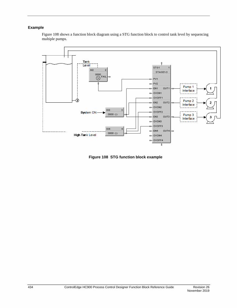
434 ControlEdge HC900 Process Control Designer Function Block Reference Guide Revision 26 November 2019
Example Figure 108 shows a function block diagram using a STG function block to control tank level by sequencing multiple pumps.
Figure 108 STG function block example

Revision 26 ControlEdge HC900 Process Control Designer Function Block Reference Guide 435 November 2019
STFL Setpoint Scheduler Stage Flags Function Block
Description The STFL label stands for the Setpoint Scheduler State Flags.
This block is part of the Setpoint Scheduler category.
Function Connects to Master block (SPS) via dedicated connection and provides logic 1(ON) state digital outputs for Scheduler modes. The State Flags block accepts the encoded master block state as an input and produces digital outputs corresponding to the current value of STFL.
Inputs STFL = this input is connected to the STFL output of the SPS function block. (See Figure 106.)
Outputs GHOLD = ON if state = 1.0, else OFF
READY = ON if state = 2.0, else OFF
HOLD = ON if state = 4.0, else OFF
RUN = ON if state = 8.0, else OFF
STOP = ON if state = 16.0, else OFF
Block properties Double click on the function block to access the function block properties dialog box.
Example Figure 106 shows a Function Block Diagram (Setpoint Scheduler Suite) using a STFL function block.

436 ControlEdge HC900 Process Control Designer Function Block Reference Guide Revision 26 November 2019
STRIG Selectable Trigger Function Block
Description The STRIG label stands for Selectable Trigger.
This block is a part of the Logic category.
Function This block allows you to select one of the following input conditions for triggering the digital output.
- The input state changes from OFF to ON. - The input state changes from ON to OFF. - Both of the above.
When this block is "triggered" its output will be ON for one cycle.
This block will also allow you to select one of the following initial scan behaviors:
- No trigger action following a Cold Start or Warm Start. - Trigger the output on the initial scan following a Cold Start; takes precedence over the input pin conditions. - Trigger the output on the initial scan following a Warm Start; takes precedence over the input pin conditions. - Trigger the output on the initial scan following a Cold Start or Warm Start; takes precedence over the input pin conditions.
Output of the block can be forced.
Inputs IN = Input signal
Outputs OUT = Output signal

Revision 26 ControlEdge HC900 Process Control Designer Function Block Reference Guide 437 November 2019
Configurable Parameters Parameter Index # Parameter Description Value or Selection
Block Order Execution Order for Block Read Only. To change block order, right-click on a Function Block and select Execution Order.
Tag name N/A 16-character tag name (ASCII characters only)
Descriptor N/A Block description
Trigger type 0 Type of input state change that will trigger the output on for one cycle.
On to off Off to on Both (On to off or Off to on)
Initial Scan 1 Type of scan No trigger Cold Start Warm Start Cold Start and Warm Start
Example Use the Selectable Trigger function block in combination with an UP/DN Counter function block to count the number of time a process input changed state from Off to ON or ON to OFF or both.
Figure 109 STRIG function block example

438 ControlEdge HC900 Process Control Designer Function Block Reference Guide Revision 26 November 2019
STSW Setpoint Scheduler State Switch Function Block
Description The STSW label stands for the Setpoint Scheduler State Switch.
This block is part of the Setpoint Scheduler category.
Function Connects to Master block (SPS) via dedicated connection and accepts digital inputs to cause scheduler mode changes. The State Switch block accepts state request digital inputs and produces an encoded output for input to the master (SPS) block.
Inputs ^JOG = OFF to ON requests JOG state
GHOLD = ON = guaranteed Hold State; ON to OFF and previous state was RUN, then return to RUN mode.
^RESET = OFF to ON requests RESET state
^RUN = OFF to ON requests RUN state
^ADV = OFF to ON requests ADVANCE state
Outputs STRQ = for connection to the STQR input of the SPS function block. This block encodes discrete inputs to a form that will convey change mode requests to the SPS block: 0.0 No Change 1.0 Jog State 2.0 Guaranteed Hold State 4.0 Reset State 8.0 Hold State 16.0 Run State 32.0 Advance state
Block properties Double click on the function block to access the function block properties dialog box.
Example Figure 106 shows a Function Block Diagram (Setpoint Scheduler Suite) using a STSW function block.
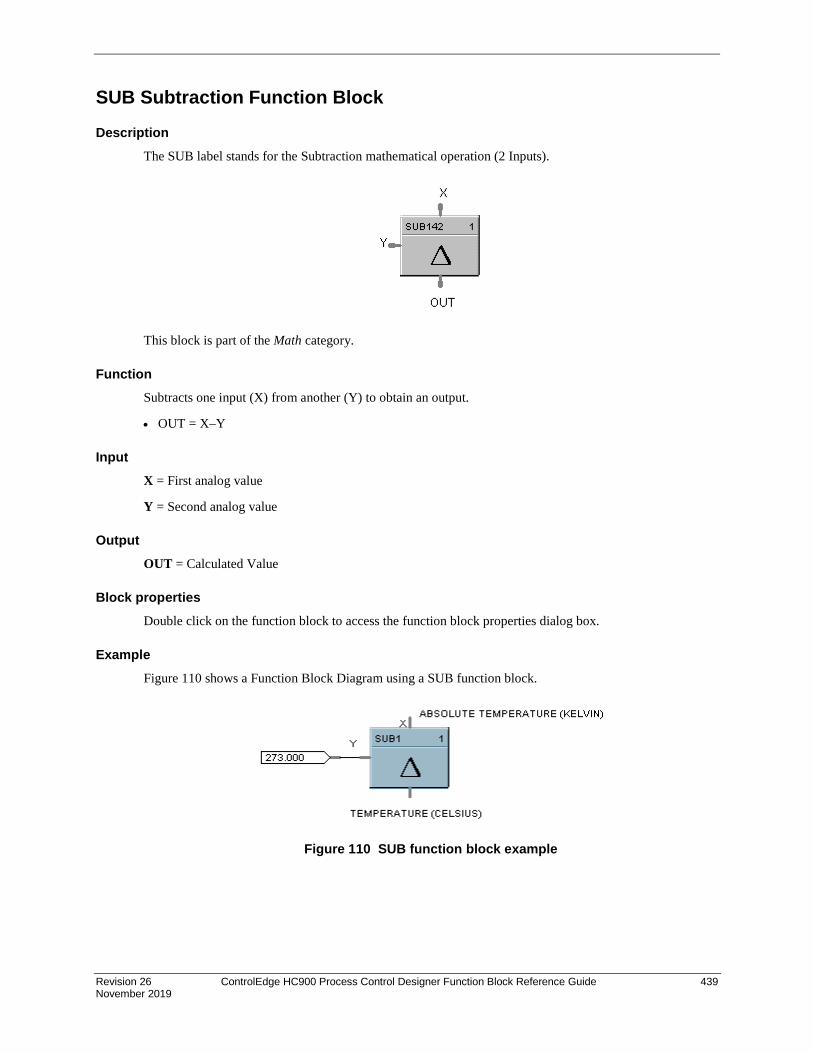
Revision 26 ControlEdge HC900 Process Control Designer Function Block Reference Guide 439 November 2019
SUB Subtraction Function Block
Description The SUB label stands for the Subtraction mathematical operation (2 Inputs).
This block is part of the Math category.
Function Subtracts one input (X) from another (Y) to obtain an output.
• OUT = X–Y
Input X = First analog value
Y = Second analog value
Output OUT = Calculated Value
Block properties Double click on the function block to access the function block properties dialog box.
Example Figure 110 shows a Function Block Diagram using a SUB function block.
Figure 110 SUB function block example

440 ControlEdge HC900 Process Control Designer Function Block Reference Guide Revision 26 November 2019
4SUB Function Block
Description The 4SUB label stands for the Subtraction mathematical operation (4 Inputs).
This block is part of the Math category.
Function Subtracts three analog inputs (X1, X2, X3) from Y input to get an output.
Input X1 = First analog input X2 = Second analog input X3 = Third analog input Y = Fourth analog input (number to subtract from)
ATTENTION
All four inputs must be connected. Unconnected inputs default to zero.
Output OUT = Calculated Value
Block properties Double click on the function block to access the function block properties dialog box.
Example Figure 111 shows a Function Block Diagram using a 4SUB function block. Y – X1 – X2 – X3 = OUT
Figure 111 4SUB function block example
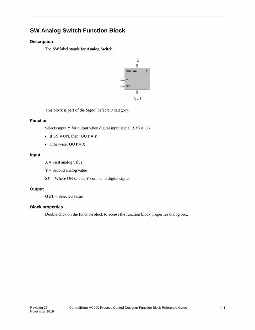
Revision 26 ControlEdge HC900 Process Control Designer Function Block Reference Guide 441 November 2019
SW Analog Switch Function Block
Description The SW label stands for Analog Switch.
This block is part of the Signal Selectors category.
Function Selects input Y for output when digital input signal (SY) is ON.
• If SY = ON, then; OUT = Y
• Otherwise, OUT = X
Input X = First analog value
Y = Second analog value
SY = Where ON selects Y command digital signal.
Output OUT = Selected value
Block properties Double click on the function block to access the function block properties dialog box.
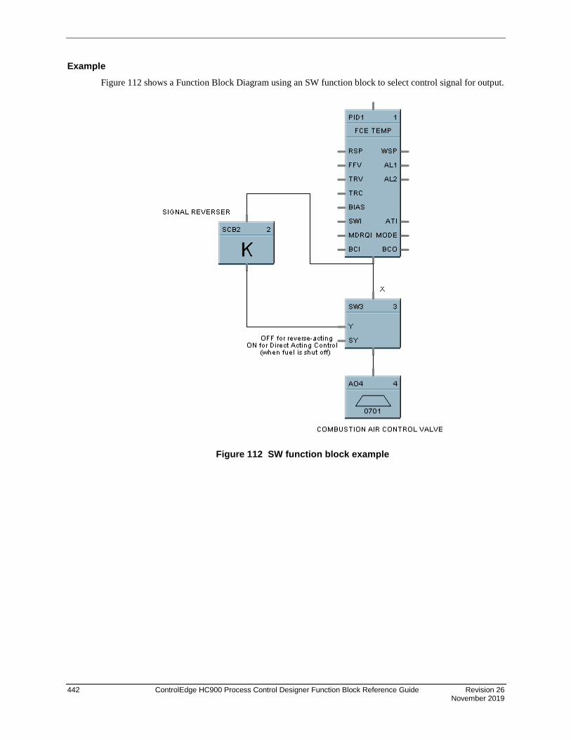
442 ControlEdge HC900 Process Control Designer Function Block Reference Guide Revision 26 November 2019
Example Figure 112 shows a Function Block Diagram using an SW function block to select control signal for output.
Figure 112 SW function block example

Revision 26 ControlEdge HC900 Process Control Designer Function Block Reference Guide 443 November 2019
SYNC Function Block
Description The SYNC label stands for Synchronize.
This block is part of the Setpoint Program category.
Function Used to synchronize the operation of two setpoint programs given the run. Hold and reset signals from each program.
Input (available for logic control of programmer) ^RESET = RESET command, when turned ON.
^HLD = HOLD command, when turned ON.
^RUN = RUN command, when turned ON.
^ADV = ADVANCE command, when turned ON
Output The status of each programmer connected to the output pins of the block are monitored. A change in state of any of the programmers is transferred to the other programmers. This occurs regardless of input pin connections. Use of block inputs is optional.
ATTENTION
Ghold status is not transferred between programmers with this block.
Block properties Double click on the function block to access the function block properties dialog box.

444 ControlEdge HC900 Process Control Designer Function Block Reference Guide Revision 26 November 2019
Example Figure 113 shows a Function Block Diagram using a SYNC function block.
Function: Synchronizes changes in setpoint program state for multiple SPP function blocks when the state of any connected SPP is changed from the Operators Panel or via a remote connection. (Analog and digital I/O blocks required to complete this function are not shown.)
Figure 113 SYNC function block example

Revision 26 ControlEdge HC900 Process Control Designer Function Block Reference Guide 445 November 2019
TAHD Track and Hold Function Block
Description The TAHD label stands for Track and Hold.
This block is part of the Auxiliary category.
Function Provides an output that tracks the value of the input (X), when a digital input signal (TC) is On; or when TC is OFF, holds output at last value of X.
• If TC = ON, then: OUT = X (TRACK)
• If TC = OFF, then: OUT = Last value of X (HOLD)
Input TC = Track command signal, when turned ON. X = Value to be tracked.
Output OUT = track and hold value of X
Block properties Double click on the function block to access the function block properties dialog box.

446 ControlEdge HC900 Process Control Designer Function Block Reference Guide Revision 26 November 2019
Example Figure 114 shows a function block diagram using a TAHD function block to track the Input signal for a PID control loop in conjunction with a digital input.
Figure 114 TAHD function block example

Revision 26 ControlEdge HC900 Process Control Designer Function Block Reference Guide 447 November 2019
TCPR Function Block
Description The TCPR label stands for Modbus/TCP Read. This block is part of the Communications category. It looks like this graphically.
Function A communication function block that expands the read capability of the Modbus/TCP Slave function block to 16 additional data points. Multiple blocks may be connected to the same Modbus/TCP Slave block.
The Modbus/TCP read block has no inputs and 16 outputs. Up to 16 registers can be configured as the source of data for the outputs.
The configuration data for each point will consist of:
• the address of the source device on the Modbus link,
• the register address of the desired data,
• and the register type: Integer, Float, or Bit Packed.
The sixteen outputs can be connected or tagged in the same manner as any other function block output.
Inputs ADDR = Slave address from associated TCPS block. (Must be connected to a TCPS block)
Outputs RD1 through RD16 – Last read value from selected address

448 ControlEdge HC900 Process Control Designer Function Block Reference Guide Revision 26 November 2019
Block properties Double click on the function block to access the function block properties dialog box.
Configuration parameters You must configure the TCPR function Block Output Pins as shown in the “Edit Selected Output Pin” portion of the dialog box. Follow the numbered sequence shown above referring to Table 117.
Table 117 TCPR function block configuration parameters
Sequence Number
Parameter Field
Action Selections Comments
1
Click on an Output Pin from the list of pins in the upper portion of the dialog box.
RD1 through RD16
The selected Output Pin will appear in the Output Pin Field.
2
Click on the “Use Register” field to assign a register to the Output pin.
RD1 through RD16
YES will be indicated in the “Register used” column when you select “Apply
3
Type in the address of the register (in Hex) on the slave device

Revision 26 ControlEdge HC900 Process Control Designer Function Block Reference Guide 449 November 2019
Sequence Number
Parameter Field
Action Selections Comments
4
From the drop down menu, select the Register Data Type
• Float • Unsigned 32 • Signed 32 • Unsigned 16 • Signed 16 • Bit Packed • Single Bit
If read as an integer, the output is converted to a floating point.
5
Select a function code for “Float, Unsigned, Signed, or Bit Packed” register data type
• Read Holding Reg – Function Code 03
• Read Input Registers – Function Code 04
Function code 03 or Function code 04 is used to read the contents of input registers in the slave.
Select a function code for “Single Bit” Register data type.
• Read Coil Status – Function Code 01
• Read Input Status – Function Code 02
Function code 01 is used to read a slave's coil's (discrete output's) ON/OFF status of the slave device in a binary data format.
Function code 02 is used to read a slave's input's (discrete input's) ON/OFF status of the slave device in a binary data format.
Output is floating point equivalent (0.0 or 1.0).
NOTE: Refer to the Communications manual for the function codes supported by the specific device.
6
Select which bit (0-15) to read when Register Data Type = Bit Packed
0 to 15 If read as a bit packed number, you must select which bit to mask (0-15).
The output will be the floating-point equivalent (0.0 or 1.0) of the masked bit.
7 You must press [APPLY] to accept the register changes.

450 ControlEdge HC900 Process Control Designer Function Block Reference Guide Revision 26 November 2019
Example Figure 115 shows a Function Block Diagram using Modbus/TCP function blocks.
Figure 115 TCPR function block example

Revision 26 ControlEdge HC900 Process Control Designer Function Block Reference Guide 451 November 2019
TCPS Function Block
Description The TCPS label stands for Modbus/TCP Slave Status. This block is part of the Communications category. It looks like this.
Function A communication function block allows the controller to act as a master device and communicate with slave devices via the Ethernet port of the controller. Requires one block per slave device, up to 32 devices maximum. Only one block may be assigned to each slave device. It supports 4 read and 4 write parameters plus provides digital indication of communication integrity.
Inputs ENABLE = [ON] Slave device is in scan - If the Enable pin IS connected, then enabling/disabling follows the state of the Enable pin of the block and the enable/disable function on the diagnostic page in the HC Designer is grayed out. If the Enable pin is NOT connected, then the user must be in Monitor mode, Monitoring TCP Modbus Diagnostics in the HC Designer, select the device to be enabled or disabled, and click the Enable (or Disable) button.
EN1 through EN4 = [ON] Data value written once per scan
WR1 through WR4 = Values to be written to the selected register
ATTENTION
• This block does not support bit packing and single bit writing.
• If the register is an integer data type, the floating point input will be rounded up prior to writing to the address register.

452 ControlEdge HC900 Process Control Designer Function Block Reference Guide Revision 26 November 2019
Outputs RD1 through RD4 = Last read value from the selected address
NO_SCAN = Scan Indication ON = Device is “Out of Scan” OFF = Device is “In Scan”.
BAD_COM = Communications Indication ON = Bad quality or device not defined OFF = Good Communications
IP_ADDR = IP Slave Address for use with TCPR and TCPW function blocks
ATTENTION
• Integer values are converted to floating point values prior to output.
• If a Modbus slave device does not respond to a request, the last output value will be maintained.
Block properties Double click on the function block to access the function block properties dialog box.
Configuration parameters The ON/OFF properties dialog box is divided into Three tab cards:
GENERAL READ WRITE
Click on the tab to access the properties for that tab.
GENERAL tab It looks like this graphically. Table 118 describes the parameters and the value or selection.
Table 118 TCPS Block General tab configuration parameters

Revision 26 ControlEdge HC900 Process Control Designer Function Block Reference Guide 453 November 2019
Properties Function Parameter Index # Parameter Description Value or Selection
Configure Modbus Slave
Slave Tag Name
N/A Description of Slave Device
16-character tag name (ASCII characters only)
Slave address and Tag Name must be unique within a control file.
Modbus Address
N/A Unit address of slave Leave at 0 unless manufacturer of the slave device states otherwise.
Modbus/TCP Address
N/A IP Address of Slave device on the link
Enter unique address (Cannot be all 0.0.0.0 or 255.255.255.255)
Default IP address = 0.0.0.0 which means slave will NOT be in scan
Modbus Double Register Format
Each IEEE 32-bit floating point number requires two consecutive registers (four bytes) starting with the register defined as the starting register for the information. The stuffing order of the bytes into the two registers differs among Modbus hosts. The selections are:
Selection Description Byte order
FP B Floating Point Big Endian Format 4, 3, 2, 1
FP BB Floating Point Big Endian with byte-swapped 3, 4, 1, 2
FP L Floating Point Little Endian Format 1, 2, 3, 4
FP LB Floating Point Little Endian with byte-swapped 2, 1, 4, 3

454 ControlEdge HC900 Process Control Designer Function Block Reference Guide Revision 26 November 2019
READ tab It looks like this graphically. Table 119 describes the parameters and the value or selection.
Table 119 TCPS Block Read tab configuration parameters
Properties Function Parameter Index # Parameter Description Value or Selection
Edit Output Pins Output Pin N/A Output pin designation Register request assigned to RD1, RD2, RD3, or RD4 pin
Use Register N/A Register Request Click on the “Use Register” field to assign a register to the Output pin.
Address (hex)
N/A Register Address Type in the address of the Read register (in Hex) on the slave device NOTE: A single configuration may contain up to 256 enabled registers.
Register Data Type
N/A Register data type From the drop down menu, select the Register Data Type
• Float
• Unsigned 32
• Signed 32
• Unsigned 16
• Signed 16
• Bit Packed
• Single Bit
If read as an integer, output is converted to floating point equivalent.

Revision 26 ControlEdge HC900 Process Control Designer Function Block Reference Guide 455 November 2019
Properties Function Parameter Index # Parameter Description Value or Selection
Function Code
N/A Several standard Modbus RTU function codes are supported. These standard function codes provide basic support for IEEE 32-bit floating point numbers and 16-bit integer register representation of instrument’s process data
Function code 03 – Read Holding Registers or Function code 04 – Read Input Registers is used to read the contents of input registers in the slave.
Supported Data Types for Function Codes 03 and 04. From the drop down menu, select a function code for “Float, Unsigned, Signed, or Bit Packed” register data type
Function code 01 – Read Coil Status is used to read the coil’s (discrete output’s) ON/OFF status of the slave device in a binary data format.
Function code 02 – Read Input Status is used to read the input’s (discrete input’s) ON/OFF status of the slave device in a binary data format.
Supported Data Types for Function Codes 01 and 02. Select a function code for “Single Bit” Register data type.
NOTE: Refer to the Communications manual for the function codes supported by the specific device.
Select Bit N/A Bit to read when Read register’s data type = Bit Packed
You must then select which bit to mask (0-15).
The output will be the floating-point equivalent (0.0 or 1.0) of the masked bit.
0-15
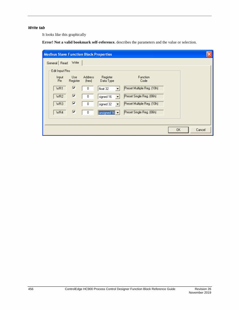
456 ControlEdge HC900 Process Control Designer Function Block Reference Guide Revision 26 November 2019
Write tab It looks like this graphically
Error! Not a valid bookmark self-reference. describes the parameters and the value or selection.

Revision 26 ControlEdge HC900 Process Control Designer Function Block Reference Guide 457 November 2019
Table 120 TCPS Block Write tab configuration parameters
Properties Function Parameter Index # Parameter Description Value or Selection
Edit Input Pins Input Pin N/A Input pin designation Register request assigned to WR1,WR2,WR3, or WR4 pin
Use Register N/A Register Request Click on the “Use Register” field to assign a register to the Input pin.
Address (hex)
N/A Register Address Type in the address of the Write register (in Hex) on the slave device
Register Data Type
N/A Register data type From the drop down menu, select the Register Data Type
• Float
• Unsigned 32
• Signed 32
• Unsigned 16
• Signed 16
• Single bit
Function Code
N/A Several standard Modbus RTU function codes are supported. These standard function codes provide basic support for IEEE 32-bit floating point numbers and 16-bit integer register representation of instrument’s process data
Preset Single Registers – Function Code 06
Preset Multiple Registers – Function Code 10 hex
Preset single bit
– Function Code 05
The function code for “Unsigned 16 or Signed 16,” register data type is 06 – Preset Single Registers* presets integer value into a single register..
The function code for “Float, Unsigned 32 or Signed 32,” register data type is 10 hex – Preset Multiple Registers* presets values into holding registers.
*automatically selected when you select “Register Data Type”
NOTE: Refer to the Communications manual for the function codes supported by the specific device.

458 ControlEdge HC900 Process Control Designer Function Block Reference Guide Revision 26 November 2019
Example Figure 116 shows a Function Block Diagram using Modbus/TCP function blocks.
Figure 116 TCPS function block example

Revision 26 ControlEdge HC900 Process Control Designer Function Block Reference Guide 459 November 2019
TCPW Function Block
Description The TCPW label stands for Modbus/TCP Write. This block is part of the Communications category. It looks like this graphically.
Function This is a communication function block that expands the write capability of the Modbus/TCP Slave function block to 8 additional data points. Multiple blocks may be connected to the same Modbus Slave block.
The Modbus write block has 8 inputs and no outputs. The Modbus destination for each of the eight inputs can be configured. An enable pin lets the data value be written once per scan.
The configuration data for each point will consist of: the address of the destination device on the Modbus link, the register address of the desired data, and the register type: Integer or Float.
Inputs EN1 through EN8 = [ON] Data value is written once per scan
WR1 through WR8 = Value to be written to the selected register address.
ADDR = Slave address from associated TCPS block. (Must be connected to TCPS block)
Outputs None

460 ControlEdge HC900 Process Control Designer Function Block Reference Guide Revision 26 November 2019
Block properties Double click on the function block to access the function block properties dialog box.
Configuration parameters You must configure the TCPW function Block Input Pins as shown in the “Edit Selected Input Pin” portion of the dialog box. Follow the numbered sequence shown above referring to Table 121.
Table 121 TCPW function block configuration parameters
Sequence Number
Parameter Field
Action Selections Comments
1
Click on an Input Pin from the list of pins in the upper portion of the dialog box.
The selected Input Pin will appear in the “Input Pin” Field.
WR1 through WR8
2
Click on the “Use Register” field to assign a register to the Input pin.
YES will be indicated in the “Register Used” column when you select “Apply” .
WR1 through WR8
3
Type in the address of the register (in Hex) on the slave device

Revision 26 ControlEdge HC900 Process Control Designer Function Block Reference Guide 461 November 2019
Sequence Number
Parameter Field
Action Selections Comments
4
From the drop down menu, select the Register Data Type
• Float
• Unsigned 32
• Signed 32
• Unsigned 16
• Signed 16
• Single bit
Several standard Modbus RTU function codes are supported. These standard function codes provide basic support for IEEE 32-bit floating point numbers and 16-bit integer register representation of instrument’s process data. (see Sequence Number 5 below)
5
The function code for “Unsigned 16 or Signed 16 register data type is (06)*
The function code for “Float, Unsigned 32 or Signed 32 register data type is (10 hex)*
*automatically selected when you select “Register Data Type”
• Preset Single Registers – Function Code 06
• Preset Multiple Registers – Function Code 10 hex
• Preset single bit
– Function Code 05
Function code 06 presets integer value into a single register.
Function Code 10 hex presets values into holding registers.
NOTE: Refer to the Communications manual for the function codes supported by the specific device.
6 You must press [APPLY] to accept the register changes.

462 ControlEdge HC900 Process Control Designer Function Block Reference Guide Revision 26 November 2019
Example Figure 117 shows a Function Block Diagram using Modbus/TCP function blocks.
Figure 117 TCPW function block example

Revision 26 ControlEdge HC900 Process Control Designer Function Block Reference Guide 463 November 2019
TGFF Toggle Flip Flop Function Block
Description The TGFF label stands for Toggle Flip-Flop.
This block is part of the Logic and Fast Logic categories.
Function Provides an ON state output when a digital input goes from OFF to ON and the previous state of the output was OFF, and an OFF state output when the digital input goes from OFF to ON and the previous state of the output was ON.
• OUT = ON when ^TOG changes from OFF to ON and the previous state of OUT was OFF.
• OUT = OFF when ^TOG changes from OFF to ON and the previous state of OUT was ON.
• Reset sets output to OFF, regardless of current state.
Input ^TOG = Digital Input RESET = Digital input ON Input = OFF output
Output OUT = Digital Output
Block properties Double click on the function block to access the function block properties dialog box.

464 ControlEdge HC900 Process Control Designer Function Block Reference Guide Revision 26 November 2019
Example Figure 118 shows a Function Block Diagram using a TGFF function block and how to tag the output.
Figure 118 TGFF function block example

Revision 26 ControlEdge HC900 Process Control Designer Function Block Reference Guide 465 November 2019
TMDT Time and Date Function Block Description
The TMDT label stands for Time and Date. This block is part of the Counters/Timers category.
Function
Controls change between Daylight Saving and Standard time. Indicates when controller time is in Daylight Saving. If the controller is using a network time server, indicates if the connection to server has failed.
Inputs
DSTI – When ON the controller will be in Daylight Saving time. When OFF the controller will be in Standard time. Use of this pin requires configuring the controller time to use DSTI.
Outputs
DSTO – ON when controller is in Daylight Saving time. OFF when controller is in Standard time. To set up Daylight Saving time, see Set Controller Time in HC Designer configuration software.
NTFAIL – ON when connection to network time server has failed. Note: controller’s time is synchronized to the time server every few hours, therefore this pin can take a few hours to detect the failure.
Block Properties
Configurable Parameters
Table 122 Time and Date configuration parameters
Properties Group Parameter Index # Parameter Description Value or Selection
Block Order N/A Execution Order for Block
Read Only. To change block order, right-click on a Function Block and select Execution Order.
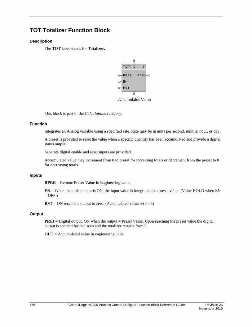
466 ControlEdge HC900 Process Control Designer Function Block Reference Guide Revision 26 November 2019
TOT Totalizer Function Block
Description The TOT label stands for Totalizer.
This block is part of the Calculations category.
Function Integrates an Analog variable using a specified rate. Rate may be in units per second, minute, hour, or day.
A preset is provided to reset the value when a specific quantity has been accumulated and provide a digital status output.
Separate digital enable and reset inputs are provided.
Accumulated value may increment from 0 to preset for increasing totals or decrement from the preset to 0 for decreasing totals.
Inputs RPRE = Remote Preset Value in Engineering Units
EN = When the enable input is ON, the input value is integrated to a preset value. (Value HOLD when EN = OFF.)
RST = ON resets the output to zero. (Accumulated value set to 0.)
Output PREI = Digital output, ON when the output = Preset Value. Upon reaching the preset value the digital output is enabled for one scan and the totalizer restarts from 0.
OUT = Accumulated value in engineering units.

Revision 26 ControlEdge HC900 Process Control Designer Function Block Reference Guide 467 November 2019
Block properties
Double click on the function block to access the function block properties dialog box.
Configuration parameters
Table 123 TOT configuration parameters
Properties Group Parameter Index # Parameter Description Value or Selection
Block Order N/A Execution Order Read Only. To change block order, right-click on a Function Block and select Execution Order.
Input Rate Input Rate N/A Input rate Select: Per Second Per Minute Per Hour Per Day
Use Preset Use Local N/A Local Preset Click on Radio Button to select and enter value in Local Preset field
1 Local Preset Value 1 to 999999
Use Remote N/A Remote Preset Click on Radio Button to select
Preset Trigger Decreasing N/A Select this to decrement from preset down to zero
Click on Radio Button to select
Increasing N/A Select this to accumulate from 0 to preset value
Click on Radio Button to select

468 ControlEdge HC900 Process Control Designer Function Block Reference Guide Revision 26 November 2019
Example Figure 119 shows Function Block Diagrams using a TOT function block.
EXAMPLE 1
EXAMPLE 2 - FLOW TOTALIZATION
Figure 119 TOT function block examples
HC900 ON Delay timers are not retentive - if the RUN input is logic 0, the timer is reset. A retentive timer has an Enable and a Reset input. As long as the timer is not reset, time will be accumulated when the Enable Input is logic 1 (ON). This permits recording the time a device such as a pump has been on.
This example uses a Totalizer function block as a retentive timer. If a fixed input of 1 is provided to the block using a Numeric Constant, the totalizer will time up to 1 at the input rate selected (per sec, per min., per hr, or per day). For example, if the “per hr” rate were selected, the output would be 1.0 after 1 hour, 2.0 after 2 hours, etc, up to the Preset value.
A counter is shown to count the number of pump cycles (On to OFF transitions).
The P4-RESET Digital Variable is used to reset the timer and counter
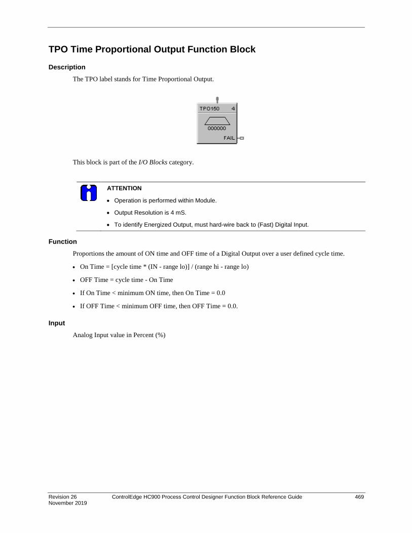
Revision 26 ControlEdge HC900 Process Control Designer Function Block Reference Guide 469 November 2019
TPO Time Proportional Output Function Block
Description The TPO label stands for Time Proportional Output.
This block is part of the I/O Blocks category.
ATTENTION
• Operation is performed within Module.
• Output Resolution is 4 mS.
• To identify Energized Output, must hard-wire back to (Fast) Digital Input.
Function Proportions the amount of ON time and OFF time of a Digital Output over a user defined cycle time.
• On Time = [cycle time * (IN - range lo)] / (range hi - range lo)
• OFF Time = cycle time - On Time
• If On Time < minimum ON time, then On Time = 0.0
• If OFF Time < minimum OFF time, then OFF Time = 0.0.
Input Analog Input value in Percent (%)
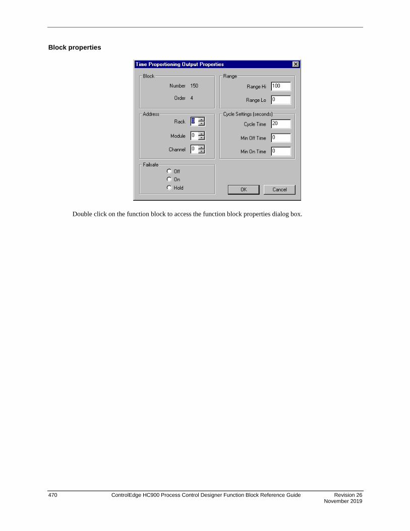
470 ControlEdge HC900 Process Control Designer Function Block Reference Guide Revision 26 November 2019
Block properties
Double click on the function block to access the function block properties dialog box.

Revision 26 ControlEdge HC900 Process Control Designer Function Block Reference Guide 471 November 2019
Configuration parameters
Table 124 TPO configuration parameters
Properties Group Parameter Index # Parameter Description Value or Selection
Address Rack 0 Address of selected Rack Enter a value: from 1 to 5
I/O Module Address of selected I/O module Enter a value: from 1 to 16
Channel Channel on selected I/O Module Enter a value: from 1 to 16*
Range Range Hi 1 High Range Value –9999 to 9999 Default = 100
Range Lo 2 Low Range Value –9999 to 9999 Default = 0
Cycle Settings Cycle Time N/A Output Cycle Time 1 to 120 seconds Default = 20
Min Off Time 4 Minimum OFF time to 15.0 seconds Default = 0.0
Min On Time 5 Minimum ON time to 15.0 seconds Default = 0.0
*For ControlEdge HC900 controller’s 32 Channel DO Module, outputs 17 through 32 may not be used for TPO (Time Proportioning Output), PPO (Position Proportioning Output) or TPSC (Three Position Step Output) output types.
Example Figure 120 shows a Function Block Diagram using a TPO function block. Time Proportioning outputs are commonly used for electrically heated applications where regulating the amount of ON time vs. OFF time of a heater is used to control temperature. In the example the TPO output is used to activate a relay output to control a heater.
Figure 120 TPO function block example

472 ControlEdge HC900 Process Control Designer Function Block Reference Guide Revision 26 November 2019
TPSC (3POS) Function Block
Description The TPSC (3POS) label stands for Three Position Step Control operation.
This block is part of the Loops category.
Function This block combines a PID controller with 3 position step control output functions to provide motor position control without position sensing. Allows the control of a valve or other actuator having an electric motor driven by two digital output channels; one to move the motor upscale, the other to move it downscale, without a feedback slidewire linked to the motor shaft.
WARNING
During Hot-Start, TPSC Outputs turn Off. After Hot-Start complete, TPSC Output resumes to original position.
Inputs PV = Process Variable Analog Input value in Engineering Units RSP = Remote Setpoint Analog Input value in Engineering Units or Percent TRV = Output Track value in Percentage (PID Output = TRV Input when TRC = ON.) TRC = Output Track Command [ON, OFF] (On -Enables TRV) (Mode = Local Override) BIAS = Remote Bias value for Ratio PID SWI = Switch Inputs (from SWO on LPSW function block) 0 = No Change 1 = Initiate Autotuning 2 = Change Control Action 4 = Force Bumpless Transfer 8 = Switch to Tune Set 1 16 = Switch to Tune Set 2

Revision 26 ControlEdge HC900 Process Control Designer Function Block Reference Guide 473 November 2019
MDRQI = External Mode request (typically connected to the MDRQO output of a MDSW function block. 0 = No Change 1 = Manual Mode Request 2 = Auto Mode Request 4 = Local Mode Request 8 = Remote Mode Request
Outputs WSP = Working Setpoint in Engineering Units for monitoring AL1 = Alarm 1 - Digital Signal AL2 = Alarm 2 - Digital Signal DIRECT = ON = Direct; OFF = Reverse ATI = Autotune Indicator (ON = Autotune in Progress) MODE = Loop mode status (typically connected to the Mode Flags block for encoding). Value indicates modes as follows: 0.0 RSP AUTO 1.0 RSP MAN 2.0 RSP Initialization Manual (See ATTENTION) 3.0 RSP Local Override (See ATTENTION) 4.0 LSP AUTO 5.0 LSP MAN 6.0 LSP Initialization Manual (See ATTENTION) 7.0 LSP Local Override (See ATTENTION) BCO - Back Calculation Output (for blocks used as Cascade Secondary). This block can only be used as a cascade secondary; therefore, no BCI input is provided. FAIL = Failed Output Indicator - Module Error
ATTENTION
When a request to change from Auto to manual is received and:
• the request comes from the operator Interface, the request is ignored.
• the request comes from the Mode Switch (MDSW) function block, the request is retained and when leaving the Initialization Mode or Local Override Mode the loop will go to manual.
Block properties Double click on the function block to access the function block properties dialog box.
Dialog box structure The TPCS properties dialog box is divided into 8 tab cards
GENERAL START/RESTART RSP RANGE/LIMIT TUNING ACCUTUNE ALARMS MOTOR
Click on the tab to access the properties for that tab.

474 ControlEdge HC900 Process Control Designer Function Block Reference Guide Revision 26 November 2019
GENERAL tab
Table 125 TPSC General tab configuration parameters
Properties Group Parameter Index # Parameter Description Value or Selection
Block Order N/A Execution Order Read Only. To change block order, right-click on a Function Block and select Execution Order.
Tag Name N/A 16 character tag name (ASCII characters only)
Descriptor N/A Block descriptor
Control Direction N/A Control Action DIRECT - Proportional action causes output to increase as process variable increases. REVERSE - Proportional action causes output to decrease as process variable increases.
SP Tracking N/A Setpoint Tracking None Track PV - When control mode is “manual”, local setpoint tracks process variable. Track RSP - When setpoint is “remote setpoint”, local setpoint tracks remote setpoint.

Revision 26 ControlEdge HC900 Process Control Designer Function Block Reference Guide 475 November 2019
START/RESTART tab

476 ControlEdge HC900 Process Control Designer Function Block Reference Guide Revision 26 November 2019
Table 126 TPSC Start/Restart tab configuration parameter
Modes and Setpoints
Permitted Mode
MAN 7
AUTO 8
Mode permitted for the initial start and power up mode.
Manual
Automatic
May select both, must select one.
Permitted Setpoint
LSP 9
RSP 10
Setpoint permitted for the initial start and power up mode.
Local Setpoint
Remote Setpoint
May select both, must select one.
Initial Mode N/A Mode at NEWSTART
Newstart is the first scan cycle following the cold start of the controller
Manual
Automatic
Select one
Setpoint for Initial Mode
N/A Setpoint at NEWSTART
Newstart is the first scan cycle following the cold start of the controller
Local Setpoint
Remote Setpoint
Select one
Power up Mode
N/A Mode at power up Manual
Retain Last Mode Same mode (auto or manual)
Select one
Power up Setpoint
N/A Setpoint at power up Local Setpoint
Retain Last LSP/RSP Same Setpoint (LSP or RSP)
Select one
Power Up Out
Power Up Out
N/A Output at Power up LAST OUT - Same as at power down.
FAILSAFE - Failsafe output value.
Failsafe Out N/A Failsafe Output Value –5 % to 105 %
Initial Setpoint Value
Use initial LSP
15 Use Initial Local Setpoint
Click on radio button to select
Initial LSP Value
16 Initial Local Setpoint Value
Enter Initial Local Setpoint Value
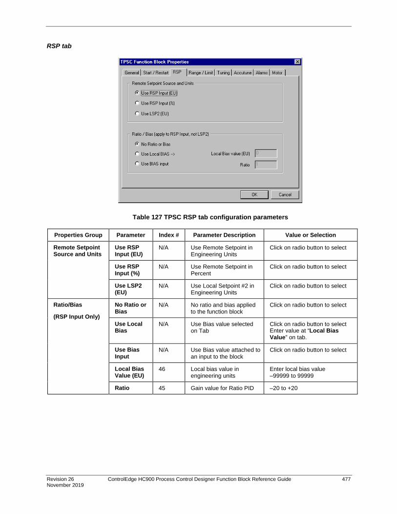
Revision 26 ControlEdge HC900 Process Control Designer Function Block Reference Guide 477 November 2019
RSP tab
Table 127 TPSC RSP tab configuration parameters
Properties Group Parameter Index # Parameter Description Value or Selection
Remote Setpoint Source and Units
Use RSP Input (EU)
N/A Use Remote Setpoint in Engineering Units
Click on radio button to select
Use RSP Input (%)
N/A Use Remote Setpoint in Percent
Click on radio button to select
Use LSP2 (EU)
N/A Use Local Setpoint #2 in Engineering Units
Click on radio button to select
Ratio/Bias
(RSP Input Only)
No Ratio or Bias
N/A No ratio and bias applied to the function block
Click on radio button to select
Use Local Bias
N/A Use Bias value selected on Tab
Click on radio button to select Enter value at “Local Bias Value” on tab.
Use Bias Input
N/A Use Bias value attached to an input to the block
Click on radio button to select
Local Bias Value (EU)
46 Local bias value in engineering units
Enter local bias value –99999 to 99999
Ratio 45 Gain value for Ratio PID –20 to +20

478 ControlEdge HC900 Process Control Designer Function Block Reference Guide Revision 26 November 2019
RANGE/LIMIT tab
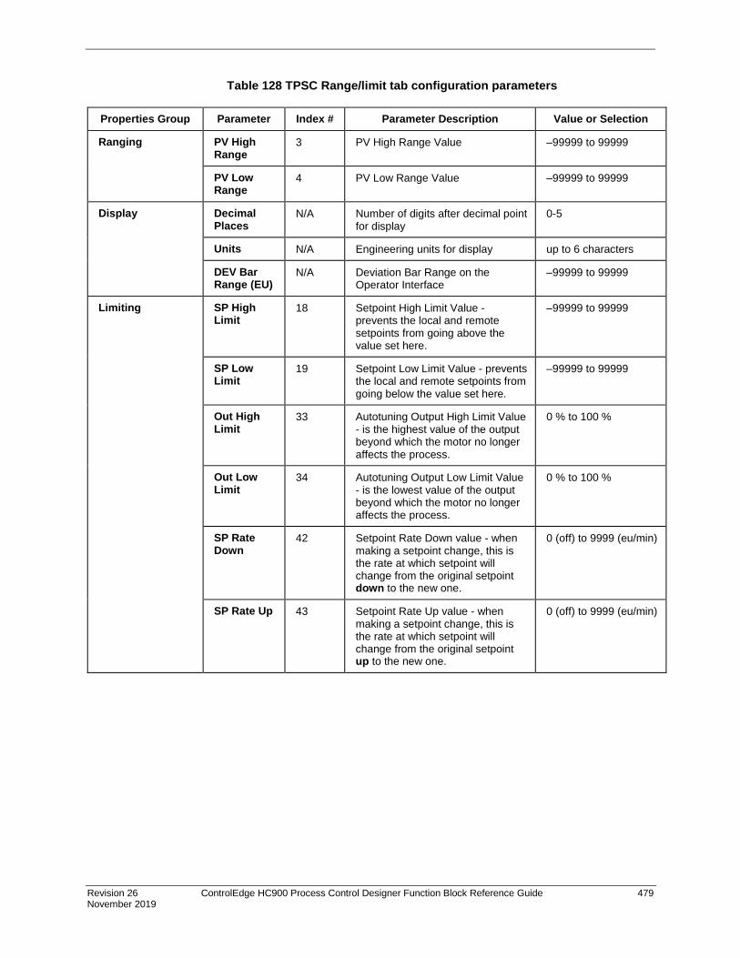
Revision 26 ControlEdge HC900 Process Control Designer Function Block Reference Guide 479 November 2019
Table 128 TPSC Range/limit tab configuration parameters
Properties Group Parameter Index # Parameter Description Value or Selection
Ranging PV High Range
3 PV High Range Value –99999 to 99999
PV Low Range
4 PV Low Range Value –99999 to 99999
Display Decimal Places
N/A Number of digits after decimal point for display
0-5
Units N/A Engineering units for display up to 6 characters
DEV Bar Range (EU)
N/A Deviation Bar Range on the Operator Interface
–99999 to 99999
Limiting SP High Limit
18 Setpoint High Limit Value - prevents the local and remote setpoints from going above the value set here.
–99999 to 99999
SP Low Limit
19 Setpoint Low Limit Value - prevents the local and remote setpoints from going below the value set here.
–99999 to 99999
Out High Limit
33 Autotuning Output High Limit Value - is the highest value of the output beyond which the motor no longer affects the process.
0 % to 100 %
Out Low Limit
34 Autotuning Output Low Limit Value - is the lowest value of the output beyond which the motor no longer affects the process.
0 % to 100 %
SP Rate Down
42 Setpoint Rate Down value - when making a setpoint change, this is the rate at which setpoint will change from the original setpoint down to the new one.
0 (off) to 9999 (eu/min)
SP Rate Up 43 Setpoint Rate Up value - when making a setpoint change, this is the rate at which setpoint will change from the original setpoint up to the new one.
0 (off) to 9999 (eu/min)

480 ControlEdge HC900 Process Control Designer Function Block Reference Guide Revision 26 November 2019
TUNING tab

Revision 26 ControlEdge HC900 Process Control Designer Function Block Reference Guide 481 November 2019
Table 129 TPSC Tuning tab configuration parameters
Properties Group Parameter Index # Parameter Description Value or Selection
Tuning Constants Prop Band 0 PB1 or Gain1
Proportional Band (PB) - is the percentage of the range of the measured variable for which a proportional controller will produce a 100 % change in its output.
0.1 to 1000
or Gain 37
PB2 or Gain2
Gain - is the ratio of output change (%) over the measured variable change (%) that caused it.
where PB is the Proportional Band (in %)
0.1 % to 1000 %
ATTENTION: Enter values for tuning set 1 and tuning set 2 in specified fields.
Reset Minutes or Repeats per Minute
2 Reset1 or 39 Reset2
RESET (Integral Time) - adjusts the controller’s output according to both the size of the deviation (SP-PV) and the time it lasts. The amount of corrective action depends on the value of Gain.
The reset adjustment is measured as how many times proportional action is repeated per minute (Repeats/minute) or how many minutes before one repeat of the proportional action occurs (Minutes/repeat).
0.02 to 50.00
Rate Minutes
1 Rate1 or 38 Rate2
RATE action, in minutes affects the controller’s output whenever the deviation is changing; and affects it more when the deviation is changing faster.
0 or 0.1 to 10.00 minutes 0 = OFF
G = 100 %PB %

482 ControlEdge HC900 Process Control Designer Function Block Reference Guide Revision 26 November 2019
ACCUTUNE tab
Table 130 TPSC Accutune tab configuration parameters
Properties Group Parameter Index # Parameter Description Value or Selection
Accutune Type Disabled N/A Disables Accutune Click on radio button to select
On Demand N/A When initiated, the controller will start controlling to the setpoint while it identifies the process, calculates the tuning constants, and begins TPSC control with the correct tuning parameters.
Click on radio button to select
Enable Fuzzy Overshoot Suppression
Click on block to select
35 Fuzzy Overshoot Suppression minimizes overshoot after a setpoint change or a process disturbance.
The fuzzy logic observes the speed and direction of the PV signal as it approaches the setpoint and temporarily modifies the internal controller response action as necessary to avoid an overshoot.
There is no change to the TPSC algorithm, and the fuzzy logic does not alter the TPSC tuning parameters.
This feature can be independently Enabled or Disabled as required by the application to work with “TUNE” On-Demand tuning.

Revision 26 ControlEdge HC900 Process Control Designer Function Block Reference Guide 483 November 2019
ALARMS tab

484 ControlEdge HC900 Process Control Designer Function Block Reference Guide Revision 26 November 2019
Table 131 TPSC Alarms tab configuration parameters
Properties Group Parameter Index # Parameter Description Value or Selection
Alarm 1 Setpoint 1 22 Alarm 1 Setpoint 1 Value - this is the value at which you want the alarm type chose below to activate
–99999 to 99999 in Engineering Units
Within the PV range when alarm type is PV or SP
Within PV span when alarm type is DEV
–5 % to 105 % when alarm type is output.
Type N/A Alarm 1 Setpoint 1 Type - select what you want Alarm 1 Setpoint 1 to represent.
Selections:
NO ALARM
PV_HIGH High PV Alarm
PV_LOW Low PV Alarm
DEV_HIGH High Deviation alarm
DEV_LOW Low Deviation alarm
SP_HIGH High Setpoint alarm
SP_LOW Low Setpoint alarm
OUT_HIGH High Output alarm
OUT_LOW Low Output alarm
Setpoint 2 23 Alarm 1 Setpoint 2 Value Same as Alarm 1 Setpoint 1
Type N/A Alarm 1 Setpoint 2 Type Same as Alarm 1 Setpoint 1
Alarm 2 Setpoint 1 24 Alarm 2 Setpoint 1 Value Same as Alarm 1 Setpoint 1
Type N/A Alarm 2 Setpoint 1 Type Same as Alarm 1 Setpoint 1
Setpoint 2 25 Alarm 2 Setpoint 2 Value Same as Alarm 1 Setpoint 1
Type N/A Alarm 2 Setpoint 2 Type Same as Alarm 1 Setpoint 1
Alarm Hysteresis
% 30 Alarm Hysteresis in % 0 % to 5 %
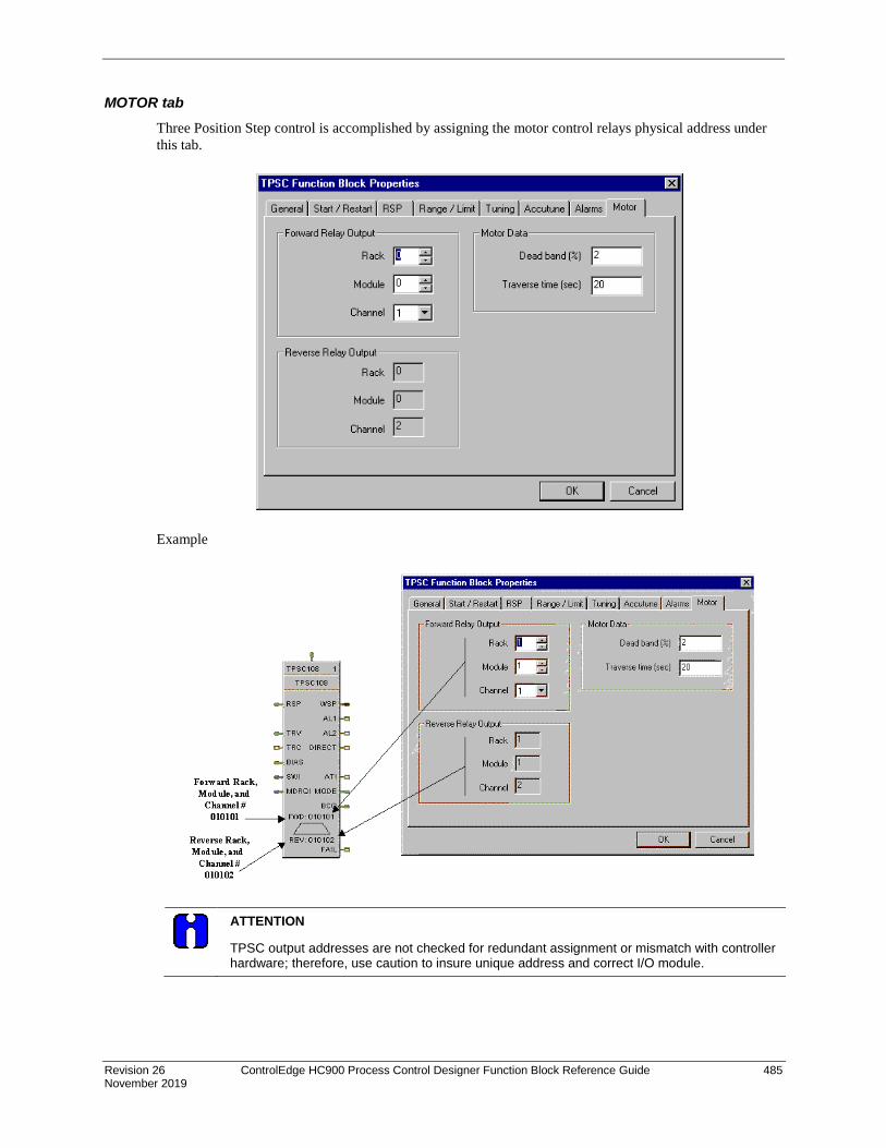
Revision 26 ControlEdge HC900 Process Control Designer Function Block Reference Guide 485 November 2019
MOTOR tab Three Position Step control is accomplished by assigning the motor control relays physical address under this tab.
Example
ATTENTION
TPSC output addresses are not checked for redundant assignment or mismatch with controller hardware; therefore, use caution to insure unique address and correct I/O module.

486 ControlEdge HC900 Process Control Designer Function Block Reference Guide Revision 26 November 2019
Table 132 TPSC Motor tab configuration parameters
Properties Group Parameter Index # Parameter Description Value or Selection
Forward Relay Output
Rack Rack Number for Forward Motor Direction
1 to 5.
Module Module Number for Forward Motor Direction
1 to 16
Channel Channel Number for Forward Motor Direction
Odd number 1 to 15*
Reverse Relay Output
Rack Rack Number for Reverse Motor Direction
1 to 5.
Module Module Number for Reverse Motor Direction
1 to 16
Channel Channel Number for Reverse Motor Direction
Even number 2 to 16*
Motor Data Deadband (%)
51 Deadband is an adjustable gap in which neither output operates
0.5 % to 5 %
Traverse Time (sec)
Motor Travel Time - the time it takes the motor to travel from 0 % to 100 %
0 to 1800 seconds
*For ControlEdge HC900 controller’s 32 Channel DO Module, outputs 17 through 32 may not be used for TPO (Time Proportioning Output), PPO (Position Proportioning Output) or TPSC (Three Position Step Output) output types.
Example
Figure 121 shows a Function Block Diagram using a TPSC function block.
Figure 121 TPSC function block example
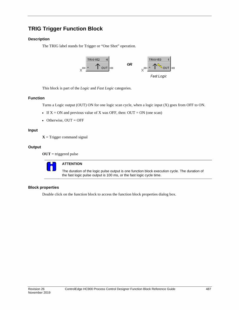
Revision 26 ControlEdge HC900 Process Control Designer Function Block Reference Guide 487 November 2019
TRIG Trigger Function Block
Description The TRIG label stands for Trigger or “One Shot” operation.
This block is part of the Logic and Fast Logic categories.
Function Turns a Logic output (OUT) ON for one logic scan cycle, when a logic input (X) goes from OFF to ON.
• If X = ON and previous value of X was OFF, then: OUT = ON (one scan)
• Otherwise, OUT = OFF
Input X = Trigger command signal
Output OUT = triggered pulse
ATTENTION
The duration of the logic pulse output is one function block execution cycle. The duration of the fast logic pulse output is 100 ms, or the fast logic cycle time.
Block properties Double click on the function block to access the function block properties dialog box.

488 ControlEdge HC900 Process Control Designer Function Block Reference Guide Revision 26 November 2019
Example Figure 122 shows a Function Block Diagram using a TRIG function block. An OFF delay timer block output is ON as long as the RST input is logic HI (ON). It can be used for time duration but must be triggered by an ON to OFF transition on the Reset input. This can be accomplished using Trigger blocks (TRIG) to create one-shot pulses which last one scan cycle. The fast logic trigger pulse will last 100 ms. while the normal logic trigger pulse will last the complete scan cycle for analog blocks. Use according to application need. A Periodic timer output pulse may also be used to start the timer for the OFF delay.
Figure 122 TRIG function block example
Off delay
AND4 output
TRIG1 output
OFDT2 output
Timing Diagram

Revision 26 ControlEdge HC900 Process Control Designer Function Block Reference Guide 489 November 2019
TRND Trend Rate Function Block
Description The TRND label stands for Trend Rate.
This block is part of the Auxiliary category.
Function The trend block is used to configure up to three storage rates for the ControlEdge HC900 trend backfill (historical data collection) feature.
Only one trend block is allowed in a configuration.
Inputs None.
Outputs CAP = storage capacity in hours
RATE1 = time in seconds of the first data storage sample rate
RATE2 = time in seconds of the second data storage sample rate
RATE3 = time in seconds of the third data storage sample rate

490 ControlEdge HC900 Process Control Designer Function Block Reference Guide Revision 26 November 2019
Configuration parameters Double clicking the block will open the dialog to configure the three data storage rates.
For each of the Log Rates click on the change button. This will open another dialog that will enable setting the rate.
Selectable rates are sample every 10 – 59 seconds, or every 1 – 59 minutes, or every 1 – 23 hours or once per day.
Table 133 TRND block configuration parameters
Parameter Index # Parameter Description Value or Selection
Log Rate 1 Sets the first of the 3 trend logging rates
10 – 59 seconds or 1 – 59 minutes or 1 – 23 hours or 1 per day
Log Rate 2 Sets the second of the 3 trend logging rates
10 – 59 seconds or 1 – 59 minutes or 1 – 23 hours or 1 per day
Log Rate 3 Sets the third of the 3 trend logging rates
10 – 59 seconds or 1 – 59 minutes or 1 – 23 hours or 1 per day

Revision 26 ControlEdge HC900 Process Control Designer Function Block Reference Guide 491 November 2019
TRPT Trend Point Function Block
Description The TRPT label stands for Trend Point.
This block is part of the Auxiliary category.
Function The trend point block is used to configure the data points to be stored by the ControlEdge HC900 trend backfill (historical data collection) feature.
The data collection rate for the points configured in the block is determined by the output pin of the TRND block that it is connected to.
Inputs X = time in seconds of the data storage rage for point in this block.
Outputs None
Configuration parameters There is a global parameter found under the HC Designer Edit menu to select whether trend points are to be configured by Modbus address or by Signal Tag. Depending on this choice double clicking the block will open one of the two following dialogs will open to configure the points to be trended by this block.
In either case, points are added by selecting the line and clicking on “Add to list”. Each trend point block can support up to 50 points. The trend function will support up to 250 points.

492 ControlEdge HC900 Process Control Designer Function Block Reference Guide Revision 26 November 2019
Figure 123 TRPT Dialog to configure points by signal tag
Figure 124 TRPT Dialog to configure points by Modbus Address

Revision 26 ControlEdge HC900 Process Control Designer Function Block Reference Guide 493 November 2019
Example
This example shows how multiple trend point blocks are attached to a single trend block to create different trend groups at the three rates.
Figure 125 TRND and TRPT function block example

494 ControlEdge HC900 Process Control Designer Function Block Reference Guide Revision 26 November 2019
UIO-AI Function Block Description
The UIO - AI label stands for Universal IO Analog Input.
This block is part of the I/O Blocks category.
Function Reads value of an UIO-Analog Input from a specified real I/O address. Convert analog input value to corresponding output (OUT) in engineering units based on the necessary scaling and conversions performed.
LINEAR - Converts analog input value to corresponding output in units based on a linear 0 % to 100 % scale and specified high and low range values +/-10% over range.
OUT = Scale x Input value + Bias where:
Input value = Analog Value in percent Input
Analog value from specified real I/O address. DIS = disable the UIO AI channel
Output OUT = Analog Input value in engineering units. FAIL = Digital status of channel Digital Low (0) = OK Digital High (1) = failed input channel
High range value - Low range value100
Scale =

Revision 26 ControlEdge HC900 Process Control Designer Function Block Reference Guide 495 November 2019
Configuration parameters
Table 134 UIO-AI configuration parameters
Properties Group Parameter Index #
Parameter Description Value or Selection
Block Order N/A Execution Order for Block
Read Only.
Address Rack This is the address of the selected Rack.
Enter a value: from 1 to 12.
I/O Module Address of selected I/O module Enter a value: from 1 to 12
Channel Channel on selected I/O Module Enter a value: 1 to 16, depending on module type.
Input Range Input Range N/A input range 4-20 mA

496 ControlEdge HC900 Process Control Designer Function Block Reference Guide Revision 26 November 2019
Range High Range Value
N/A For Linear Inputs Only - output value that corresponds to 100 % input value
For example: Actuation Input = 4-20mA Process variable = Flow Range of Flow = 0 to 250 gal/min High Range Display Value = 250 Low range Display Value = 0 Then 20mA = 250, 4mA = 0
Enter a value:
- 99999 to 99999
Default = 100
Low Range Value
N/A For Linear Inputs Only - output value that corresponds to 0 % input value For example: See "High Range Value"
Enter a value:
- 99999 to 99999
Default = 0
Disable Channel Output Value 8 The output value when the AI channel is disabled. Disable = ON
Enter a value
Default = 0
Settings Filter Time (sec)
N/A A software digital filter is provided for the input designated to smooth the input. You can configure the first order lag time constant from 1 to 120 seconds. 0=no filter
Enter a value:
0 to 120 seconds
Bias 7 Bias is used to compensate the input for drift of an input value due to deterioration of a sensor, or some other cause.
Enter a value:
- 9999 to 99999
Failsafe Use Value field
N/A The output value to which the output will go to protect against the effects of failure of the controller or no communication to IO module.
Enter a value in Engineering Units
- 9999 to 99999
Use Value N/A Use the value entered in the appropriate field.
Click on Radio button to select
Downscale N/A LINEAR OUT = Value set at "Low range value" field.
Click on Radio button to select
Upscale N/A LINEAR OUT = Value set at "High range value" field.
Click on Radio button to select
Line Monitoring Short circuit Detection
Open Wire Detection
N/A Short circuit detection check enable
Open Wire detection check enable
Read only

Revision 26 ControlEdge HC900 Process Control Designer Function Block Reference Guide 497 November 2019
Example The below figure shows Function block diagram:
Figure 126 UIOAI function block example

498 ControlEdge HC900 Process Control Designer Function Block Reference Guide Revision 26 November 2019
UIO-AO Function Block
Description The UIO-AO label stands for Universal Analog Output.
This block is part of the I/O Blocks category.
Function Range High and Range Low are used to specify the Engineering Unit values for 100 % and 0 % of this block’s input span. For reverse outputs, Range High may be set to a value less than Range Low.
The output range high and range low values (4-20 maximum) set the milliamp output values that correspond to the 0 % to 100 % span limits of the inputs.
Note:
• Currently maximum of 400 UIO AO channels supported in one system/CDE
• Safety UIO module will drive configured failsafe value only when IO module lose communication to controller else it will drive field value to unpowered for any other IO module diagnostic faults.
Input X = Input Analog Signal
^RSTRT = Restart Signal –
When used, a positive (rising) input pulse releases OUT from its failsafe value and FAIL pin from its ON state. Reset to this pin is MUST for clearing this channel fault after repair. This allows for the replacement or repair of the failed AO module or failure condition and operator controlled release.
DIS = Disable Signal – When used and made ON, disables the AO Channel and results in disabling of ^RSTRT functionality. If DIS pin left unconnected or made OFF, results in Normal Operation i.e. it enables the function block.
Output OUT = Converted value sent to specified real I/O address (mA). FAIL = Failed Output indication - Channel Error
RDBKCRNT = Read back current (in mA)

Revision 26 ControlEdge HC900 Process Control Designer Function Block Reference Guide 499 November 2019
Block properties
Double click on the function block to access the function block properties dialog box.

500 ControlEdge HC900 Process Control Designer Function Block Reference Guide Revision 26 November 2019
Configuration parameters AO’s Address starts at Module 4.
Table 135 Analog output configuration parameters
Parameter Index # Parameter Description Value or Selection
Block Order N/A Execution Order for Block Read Only
Rack Address This is the address of the selected Rack.
1 to 12
I/O Module Address
Address of selected I/O module 1 to 12
Channel Address
Channel on selected I/O Module
9 to 16
Range Hi 5 High Range Value Engineering Unit - value of input that corresponds to 100 % output value
99999 to 999999 Default = 100
Range Low 6 Low Range Value Engineering Unit - value of input that corresponds to 0 % output value
99999 to 999999 Default = 0.0
mA at range High
7 Value of mA output that corresponds to 100 % output signal (for example: 20 mA)
3 to 20 Default = 20
mA at Low Range
8 Value of mA output that corresponds to 0 % output signal (for example: 4 mA)
3 to 20 Default = 4
mA at range High Limit
N/A Value of mA that you want to set the High Range Limit
2.4 to 21 Default = 21
mA at Low Range Limit
N/A Value of mA that you want to set the Low Range Limit
2.4 to 21 Default = 2.4
Failsafe Value N/A USE VALUE sets the output to the programmed value when failure is detected.
0 to 21 mA Default = 0
Failsafe Type 3 Type of Failsafe High - sets the output of the block to the High Output Range Value when failure is detected Low - sets the output of the block to the Low Output Range Value when failure is detected Hold - maintains the last value of the block just prior to the failure being detected Click on Radio Button to select
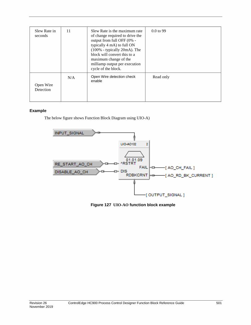
Revision 26 ControlEdge HC900 Process Control Designer Function Block Reference Guide 501 November 2019
Slew Rate in seconds
11 Slew Rate is the maximum rate of change required to drive the output from full OFF (0% - typically 4 mA) to full ON (100% - typically 20mA). The block will convert this to a maximum change of the milliamp output per execution cycle of the block.
0.0 to 99
Open Wire Detection
N/A Open Wire detection check enable
Read only
Example The below figure shows Function Block Diagram using UIO-A)
Figure 127 UIO-AO function block example

502 ControlEdge HC900 Process Control Designer Function Block Reference Guide Revision 26 November 2019
UIO-DI Function Block
Description The UIO-DI label stands for Universal IO Digital Input.
This block is part of the I/O Blocks categories.
Function Provides the digital status of a digital input point and provides interface to other algorithms and functions. The output status may be inverted.
If Digital Point is ON, then OUT = ON
Input DIS = disable the UIO DI channel
Output OUT = Digital Signal
FAIL = Failed Input indication - Module error
Block properties
Double click on the function block to access the function block properties dialog box.

Revision 26 ControlEdge HC900 Process Control Designer Function Block Reference Guide 503 November 2019
Configuration parameters
Table 136 UIO Digital input configuration parameters
Parameter Index # Parameter Description Value or Selection
Rack Address N/A Address of selected I/O rack From 1 to 12
I/O Module Address
0 Address of select I/O Module From 1 to 12
Channel Address N/A Channel on selected I/O Module From 1 to 16,
Failsafe ON N/A set the output of the block to ON when failure is detected
Click on radio button to select
Failsafe OFF N/A set the output of the block to OFF when failure is detected
Click on radio button to select
Failsafe HOLD N/A hold the output at the last value just prior to the failure being detected
Click on radio button to select
Invert 4 If INVERT is selected, OUT = inverse of physical input. The slash will be present in the CONTACT symbol only when the invert box is selected on the dialog box.
Debounce
(msec) N/A DI Debounce time
0= no debounce Enter a value: 0 to 50 milliseconds
SOE Enable N/A Enables Sequence of events (SOE events will be generated even in channel disabled state for field value changes)
Click on check box to enable SOE
Short circuit Detection
Open Wire Detection
N/A Short circuit detection check enable Open Wire detection check enable
Click on Radio to select or deselect

504 ControlEdge HC900 Process Control Designer Function Block Reference Guide Revision 26 November 2019
Example The below figure shows a Function Block Diagram using a UIO-DI function block.
Figure 128 UIODI function block example

Revision 26 ControlEdge HC900 Process Control Designer Function Block Reference Guide 505 November 2019
UIO-DO Function Block
Description The UIO-DO label stands for Universal Digital Output.
This block is part of the I/O Blocks categories.
Function Provides a digital status from the algorithms and functions to a physical logic output. The output status may be inverted.
Note: • Safety UIO module will drive configured failsafe value only when IO module lose communication
to controller else it will drive field value to unpowered for any other IO module diagnostic faults. • It is required to reset DO channel to resume from failsafe state for new DO block after hotstart. • In the openwire condition, performing reset on RUIO DO, channel status become healthy for 9 sec
and then detects the openwire. During this period output changes as per the input.
Input X = Input Status Signal
^RSTRT = Restart Signal – When used, a positive (rising) input pulse releases OUT from its failsafe value and FAIL pin from its ON state. Reset to this pin is MUST for clearing this channel fault after repair. This allows for the replacement or repair of the failed DO module or failure condition and operator controlled release.
DIS = Disable Signal – When used and made ON, disables the DO Channel and results in disabling of ^RSTRT functionality. If DIS pin left unconnected or made OFF, results in Normal Operation i.e. it enables the function block
Output
FAIL = Failed Input indication - Module error
OUT = Physical Output Value
RDBKCRNT = Read back current (in mA). This values will have deviation of 1 to 20mA as field current goes high.

506 ControlEdge HC900 Process Control Designer Function Block Reference Guide Revision 26 November 2019
Block properties
Double click on the function block to access the function block properties dialog box.
Table 137: Configurable Parameters UIO DO
Parameter
Parameter Description Value or Selection
Rack Address N/A Address of selected I/O rack From 1 to 12
I/O Module Address
0 Address of select I/O Module From 1 to 12
Channel Address
N/A Channel on selected I/O Module From 1 to 16.
Failsafe ON N/A set the output of the block to ON when failure is detected
Click on radio button to select
Failsafe OFF N/A set the output of the block to OFF when failure is detected
Click on radio button to select
Failsafe HOLD
N/A hold the output at the last value just prior to the failure being detected
Click on radio button to select
Invert 4 If INVERT is selected, OUT = inverse of physical input. The slash will be present in the CONTACT symbol only when the invert box is selected on the dialog box.

Revision 26 ControlEdge HC900 Process Control Designer Function Block Reference Guide 507 November 2019
Short circuit Detection
Open Wire Detection
N/A Short circuit detection check
enable Open Wire detection check
enable
Read only
Example The below figure shows a Function Block Diagram using a UIO-DO function block.
Figure 129 UIODO function block example
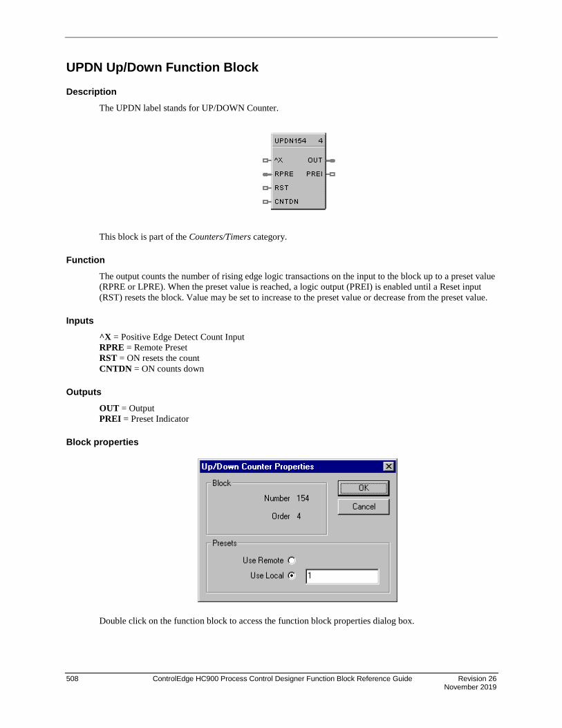
508 ControlEdge HC900 Process Control Designer Function Block Reference Guide Revision 26 November 2019
UPDN Up/Down Function Block
Description The UPDN label stands for UP/DOWN Counter.
This block is part of the Counters/Timers category.
Function The output counts the number of rising edge logic transactions on the input to the block up to a preset value (RPRE or LPRE). When the preset value is reached, a logic output (PREI) is enabled until a Reset input (RST) resets the block. Value may be set to increase to the preset value or decrease from the preset value.
Inputs ^X = Positive Edge Detect Count Input RPRE = Remote Preset RST = ON resets the count CNTDN = ON counts down
Outputs OUT = Output PREI = Preset Indicator
Block properties
Double click on the function block to access the function block properties dialog box.

Revision 26 ControlEdge HC900 Process Control Designer Function Block Reference Guide 509 November 2019
Configuration parameters
Table 138 Up/down configuration parameters
Properties Group Parameter Index # Parameter Description Value or Selection
Presets Local Preset
0 Local Preset 1 to 99999
Use Remote Preset
1 On selects remote preset Click on Box to select
Example Figure 130 shows a Function Block Diagram using a UPDN function block. This example uses a Totalizer function block as a retentive timer. If a fixed input of 1 is provided to the block using a Numeric Constant, the totalizer will time up to 1 at the input rate selected (per sec, per min., per hr, or per day). For example, if the “per hr” rate were selected, the output would be 1.0 after 1 hour, 2.0 after 2 hours, etc, up to the Preset value.
A counter is shown to count the number of pump cycles (On to OFF transitions).
The P4-RESET Digital Variable is used to reset the timer and counter
Figure 130 UPDN function block example

510 ControlEdge HC900 Process Control Designer Function Block Reference Guide Revision 26 November 2019
VLIM Velocity Limiter Function Block
Description The VLIM label stands for Velocity (Rate) Limiter.
This block is part of the Auxiliary category.
Function Limits the rate at which an analog input value (X) can change, when a digital input signal (EN) is ON. Individual rate of change limits are configured for an increasing and a decreasing X, respectively.
Separate digital status outputs indicate when High (H) or Low (L) rate limits are active.
• If EN = OFF or system state = NEWSTART*, then: OUT = X, L = OFF, H = OFF.
• If EN = ON and OUT < X, then: OUT moves toward X at Increasing RATE limit, L = OFF, H = ON until OUT = X.
• If EN = ON and OUT > X, then: OUT moves toward X at Decreasing RATE, L = ON until OUT = X, H = OFF.
* Newstart is the first scan cycle following the cold start of the controller.
Input X = Analog Value (Primary Input)
EN = Enable Input command
Output OUT = Rate Limited Input Value
H = High Rate alarm indication
L = Low Rate alarm indication

Revision 26 ControlEdge HC900 Process Control Designer Function Block Reference Guide 511 November 2019
Block properties
Double click on the function block to access the function block properties dialog box.
Configuration parameters
Table 139 VLIM Configuration Parameters
Properties Group Parameter Index # Parameter Description Value or Selection
Set Limits Increase Rate Limit
0 Limits the increasing rate at which the analog input value can change
0 to 99999 (eu/min)
Decrease Rate Limit
1 Limits the decreasing rate at which the analog input value can change
0 to 99999 (eu/min)
Example Figure 131 shows a VLIM function block that limits the increasing or decreasing rate at which the output can change based on user specified limits when the Enable input is ON (1).
Figure 131 VLIM function block example

512 ControlEdge HC900 Process Control Designer Function Block Reference Guide Revision 26 November 2019
WCON Write Constant Function Block
Description The WCON label stands for Write Constant. This block is part of the Auxiliary category.
Function Writes the numerical value of selected configuration parameter to a given control block. If EN is ON, the selected parameter is changed to the value of X.
ATTENTION
Not valid for all blocks. Also, for SIL-compliant controllers the Write Constant function block may be used on both Process and Safety worksheets, but the selected function block to write to must be located on a Process worksheet. Writing to blocks located on a Safety worksheet is not allowed, unless the Write Constant function block itself is on a Safety worksheet.
Input X = Value to be written (invalid for parameters of type other than BOOL or REAL)
EN = Enable command
Configuration parameters
Parameter Index # Parameter Description
Value or Selection
Block Number N/A Number of control block that contains desired configuration parameter
101 to 500(CPU C30) 101 or 2100(CPU C50) 101 to 5100 (CPU C70/C75)
Parameter Index # N/A Index number of configuration parameter to be modified
Select the index number of the required parameter from the specific function block reference data

Revision 26 ControlEdge HC900 Process Control Designer Function Block Reference Guide 513 November 2019
1. Double-click on the function block to access the "Write Constant" dialog shown below:
2. Select the Block Number of the Target Block from the pull-down list. Note that function blocks located on a Safety worksheet in an SIL-compliant configuration will not be listed, unless the Write Constant block is on a Safety worksheet itself.
3. Enter the Index number of the desired configuration parameter of the Target Block. Check the block’s properties page for details.
4. Click on the OK button to complete the configuration.
The block number and parameter index will appear on the front of the WCON function Block; B:105 I:5 in the above example.

514 ControlEdge HC900 Process Control Designer Function Block Reference Guide Revision 26 November 2019
WTUN Write Tuning Constants Function Block
Description The WTUN label stands for Write Tuning Constants.
This block is part of the Loops category.
Function Writes the numerical value of Gain, Rate, and Reset to a Target PID, TPSC, or CARB block without any operator interaction.
Select the target block number from the specific function block diagram and enter it in the appropriate field in the “Write Tune Constants” dialog box.
• If EN is ON, then the tuning constants are set to the Gain, Rate, and Reset input values..
• WTUN values written to Loop Tuning Set #1 only.
• WTUN will only send values within each Range Limit.
ATTENTION
Invalid for block number whose type is other than PID, CARB, or TPSC.
If the target block is in AUTO mode, tuning parameter change will cause a bump in the output.
If any input value is “out-of-range”, no values will be written.
Value to GAIN/ PB input applies to active Tuning Constant.
Input GAIN = Value for GAIN tuning constant RSET = Value for RESET tuning constant (Integration time) RATE = Value for RATE tuning constant (Derivative time) EN = Enable command
ATTENTION
The three analog inputs can originate as recipe items or be calculated for adaptive control.

Revision 26 ControlEdge HC900 Process Control Designer Function Block Reference Guide 515 November 2019
Target block number
Double click on the function block to access the “Target Block Number” dialog box.
Enter the Target Block number in the appropriate field. Selections are from 101 to 500(Model C30), 101 to 2100 (Model C50), 101 to 5100 (Model C70/C75).
Example Figure 132 shows a Function Block Diagram using a WTUN function block to write Tuning Parameters to a PID function block.
Figure 132 WTUN function block example

516 ControlEdge HC900 Process Control Designer Function Block Reference Guide Revision 26 November 2019
WVAR Write Variable Function Block
Description The WVAR label stands for Write Variable. This block is part of the Auxiliary category.
Function Writes a new value to a selected Variable number.
If EN is ON, then the Variable selected is set to the value of X. (For example: X = a constant value)
For SIL-compliant controllers the Write Variable function block may be used on both Process and Safety worksheets. Writing to Variables located on a Safety worksheet is not allowed, unless the Write Variable function block itself is on a Safety worksheet .
Designer software V6.005 and above provides connections from the process to safety worksheet variables for NON-critical safety functions. The safety variable must be enabled for non-critical safety functions; this variable attribute places the variable into the Select variables list on process worksheets.
Inputs X = Value to be written to the selected variable
EN = Enable command
Configurable Parameter
Target write variable number
1. Double-click on the function block to access the "Write Variable Number" dialog shown below:

Revision 26 ControlEdge HC900 Process Control Designer Function Block Reference Guide 517 November 2019
2. Click on the Select Variable button to access the “Select Variable” dialog shown below:
Once a variable is assigned the "Find Variable" button will change the worksheet focus to the associated variable.
> Selecting the OK button keeps new worksheets focus.
> Selecting the "Cancel" button returns the worksheet focus to the WVAR worksheet.
This functionality allows the configurator designer to verify the associated variable connection.
Note: If the WVAR's variable is deleted from the configuration the WVAR association will be lost/ unassigned.
3. From the pull-down selector select from:
• All WorkSheets
• All Variables
• Analog Variables
• Digital Variables
4. In the All Worksheets list box select the desired worksheets list -"All WorkSheets", "Process WorkSheets", "Safety WorkSheets".
5. In the list box, select the desired Variable. Note that Variables located on a Safety worksheet in an SIL-compliant configuration will only be listed if the associated variables NON-Safety Critical radio button has been enabled or, unless the Write Variable function block is on a Safety worksheet.
NOTE: Setting enabling the NON safety Critical radio button confirms that the variable is not being used in a safety critical function.
6. Click the OK button to return to the “Write Variable Number” dialog.
7. Click the OK button to complete the configuration.
The Target block number will appear on the front of the WVAR function Block.

518 ControlEdge HC900 Process Control Designer Function Block Reference Guide Revision 26 November 2019
XFR Bumpless Analog Transfer Switch Function Block
Description The XFR label stands for Bumpless Analog Transfer Switch.
This block is part of the Signal Selectors category.
Function Provide “bumpless” switching between two analog input values (X, Y) that is triggered by a digital input signal (*SY). When switched, the output ramps to the new value at a specified rate.
The rate at which the output (OUT) changes to a switched value (Y or X) is set by YRATE and XRATE configuration values, respectively.
• If SY is switched to ON, then: OUT changes to Y value at YRATE.
• If SY is switched to OFF, then: OUT changes to X value at XRATE.
• When OUT reaches the selected target input, OUT tracks the selected input (until SY changes).
Input X = First analog value. Y = Second analog value. SY = Switch to Y command digital signal
Output OUT = Selected Value
Block properties
Double click on the function block to access the function block properties dialog box.
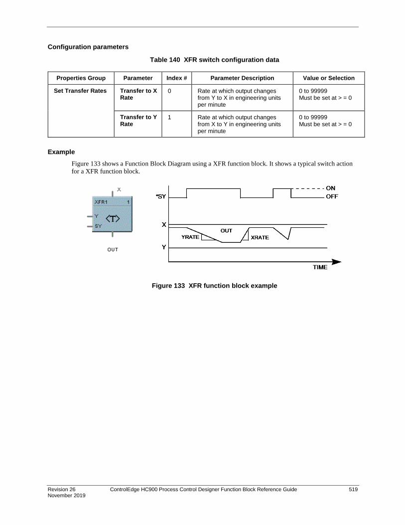
Revision 26 ControlEdge HC900 Process Control Designer Function Block Reference Guide 519 November 2019
Configuration parameters
Table 140 XFR switch configuration data
Properties Group Parameter Index # Parameter Description Value or Selection
Set Transfer Rates Transfer to X Rate
0 Rate at which output changes from Y to X in engineering units per minute
0 to 99999 Must be set at > = 0
Transfer to Y Rate
1 Rate at which output changes from X to Y in engineering units per minute
0 to 99999 Must be set at > = 0
Example Figure 133 shows a Function Block Diagram using a XFR function block. It shows a typical switch action for a XFR function block.
Figure 133 XFR function block example

520 ControlEdge HC900 Process Control Designer Function Block Reference Guide Revision 26 November 2019
XOR Function Block
Description The XOR label stands for the Exclusive OR Boolean operation.
This block is part of the Logic and Fast Logic categories.
Function Turns a digital output signal (OUT) ON if only one of two digital input signals (X, Y) is ON. Otherwise, the output is OFF.
• If X = OFF and Y = ON, then: OUT = ON.
• If X = ON and Y = OFF, then: OUT = ON.
• If X = ON and Y = ON, or X = OFF and Y = OFF, then OUT = OFF.
Input X = First Digital Signal Y = Second Digital Signal
Output OUT = resultant digital signal
Block properties Double click on the function block to access the function block properties dialog box.
Example Figure 134 shows a Function Block Diagram using a XOR function block. In the example, if pressure input 1 or 2 is high or low, flow is disabled. If only one pressure input is ON, flow is enabled.
Figure 134 XOR function block example

Revision 26 ControlEdge HC900 Process Control Designer Function Block Reference Guide 521 November 2019
5XYRB Function Block
Description The 5XYRB label stands for XYR5000 base radio slave status block.
This block is a part of the Communications category.
Function This block allows the ControlEdge HC900 controller to act as a Modbus master device and communicate with XYR5000 base radios via the serial port of the controller. Configuration of the ControlEdge HC900 master requires one block per base radio, up to 32 base radios or 1024 parameters maximum. Only one block may be assigned to each XYR5000 base radio slave device.
The block supports 10 read parameters from the XYR5000 plus it provides digital indication of communication integrity. For attached transmitters there is a separate 5XYRT block which is connected to 5XYRB via the address (ADDR) output of the 5XYRB block. Since all the parameters of 5XYRB block have fixed Modbus register addresses, there is no configuration data associated with addressing of the parameters. All outputs can be tagged in the same manner to any other function block output.
NOTE 1: To read proper values of all transmitter parameters when connecting an ControlEdge HC900 to the XYR5000 system, the XYR5000 base radio must be set to "Register Mapping Mode."
If a XYR5000 base radio slave device does not respond to a request, the last output value will be maintained.
NOTE 2: The output values of the 5XYRB block may be added to the Custom Modbus Map without the need to assign tags to the output pins.
522 ControlEdge HC900 Process Control Designer Function Block Reference Guide Revision 26 November 2019
Input ENABLE = Digital input ON when XYR5000 base station is in scan. Digital input OFF when XYR5000 base station is out of scan.
Output DEV STAT = Last read value of XYR5000 base radio device status. (O = offline, 1 = online)
EXP CNT = Number of Expected Transmitters communicating to the base station.
TX CNT = Number of Transmitters actually communicating with the base radio.
TxS1-16 = Online/Offline status of transmitters 1-16. Connect to Digital Decoder block for transmitter status.
TxS17-32 = Online/Offline status of transmitters 17-32. Connect to Digital Decoder block for transmitter status.
TxS33-48 = Online/Offline status of transmitters 33-48. Connect to Digital Decoder block for transmitter status.
TxS49-64 = Online/Offline status of transmitters 49-64. Connect to Digital Decoder block for transmitter status.
TxS65-80 = Online/Offline status of transmitters 65-80. Connect to Digital Decoder block for transmitter status.
TxS81-96 = Online/Offline status of transmitters 81-96. Connect to Digital Decoder block for transmitter status.
TxS97-100 = Online/Offline status of transmitters 97-100. Connect to Digital Decoder block for transmitter status.
NO_SCAN = Scan Indication. ON = Device is "Out of Scan". OFF = Device is "In Scan".
BAD_COM = Communications Indication. ON = Bad quality or device not defined. OFF = Good Communications.
ADDR = Connection pin used to connect the 5XYRB base radio block to the 5XYRT transmitter block.

Revision 26 ControlEdge HC900 Process Control Designer Function Block Reference Guide 523 November 2019
Configuration parameters Double click on the function block to access the function block properties dialog box.
Properties Group Parameter Index # Parameter Description Value or Selection
Configure Modbus Slave
Slave Tag Name
0 Description of XYR5000 device 16 character tag name (ASCII characters only).
Slave address and Tag Name must be unique within a control file.
Modbus address
1 Address of XYR5000 base radio on the link.
Enter unique address. address, range 1 to 247.
Default address = 255 which means XYR5000 base radio slave will NOT be in scan
Modbus Double Register Format
Each IEEE 32-bit floating point number requires two consecutive registers (four bytes) starting with the register defined as the starting register for the information. The stuffing order of the bytes into the two registers differs among Modbus hosts. The selections are:
Selection Description Byte order
FP B Floating Point Big Endian Format (recommended format) 4, 3, 2, 1
FP BB Floating Point Big Endian with byte-swapped 3, 4, 1, 2
FP L Floating Point Little Endian Format 1, 2, 3, 4
FP LB Floating Point Little Endian with byte-swapped 2, 1, 4, 3

524 ControlEdge HC900 Process Control Designer Function Block Reference Guide Revision 26 November 2019
Example Figure 135 shows a Function Block Diagram using a 5XYRB function block.
Figure 135 5XYRB function block example

Revision 26 ControlEdge HC900 Process Control Designer Function Block Reference Guide 525 November 2019
5XYRT Function Block
Description The 5XYRT label stands for XYR5000 Transmitter slave status block.
This block is a part of the Communications category.
Function This communication function block expands the read capability of the 5XYRB Slave function block to access parameters of XYR5000 Transmitters. 5XYRB block’s ADDR output is connected to the ADDR input of this block to access all the parameters. The 5XYRT block has 12 output parameters which are supplied by 5XYRB block. Since these parameters have fixed Modbus register addresses, there is no configuration data associated with this block. All outputs can be connected or tagged in the same manner as any other function block output.
If communication between the ControlEdge HC900 and the XYR5000 base radio is lost, the last read values will be supplied on the 5XYRT outputs.
Input ADDR = Input pin used to connect the 5XYR transmitter block to the 5XYRB base radio block. Must be connected to 5XYRB block’s ADDR output pin.

526 ControlEdge HC900 Process Control Designer Function Block Reference Guide Revision 26 November 2019
Output PR SENS = Primary Sensor Value.
SC SENS = Secondary Sensor Value.
TR SENS = Tertiary Sensor Value.
ONLINE = Transmitter online status. 1 = online, 0 = offline.
LOW BAT = Low Battery condition. 1 = low battery, 0 = battery ok.
ALARM = Alarm condition. 1 = alarm, 0 = no alarm.
SENS ERR = Sensor error condition. 1 = error, 0 = ok.
SENS OVR = Sensor over range condition. 1 = over range, 0 = ok.
SYS ERR = System error condition. 1 = system error, 0 = ok.
INP1 CLSD = switch input 1 closed. 1 = closed, 0 = open.
INP2 CLSD = switch input 2 closed. 1 = closed, 0 = open.
SQRT FN = square root function. Square root of primary Differential Transmitter output.
Configurable Parameters Parameter Index # Parameter Description Value or Selection
Transmitter Reference Name
0 Description of XYR5000 transmitter
16 character name (ASCII characters only).
Slave address and Tag Name must be unique within a control file.
Node ID 1 ID of transmitter Enter node ID. (Valid Range is 1 to 100).
Default ID = 0 which means data will NOT be read.

Revision 26 ControlEdge HC900 Process Control Designer Function Block Reference Guide 527 November 2019
Example
Figure 136 5XYRT function block example

528 ControlEdge HC900 Process Control Designer Function Block Reference Guide Revision 26 November 2019
6XYRT Function Block The 6XYRT label stands for XYR6000 transmitter status block.
This block is a part of the Communications category.
Function Use this block to read the process variables and device status of any XYR6000 transmitter. To access XYR6000 parameters, connect this block’s ADDR input to the ADDR output of the XYR6000 Gateway (6XYRWG) block.
Five parameters—PV1, PV2, PV3, PV4 and DEV_STAT—are read from the XYR6000 transmitter. DEV_STAT value contains several statuses of the transmitter, and each status from DEV_STAT is assigned its own output pin of this block.
If a 6XYRWG gateway does not respond to a request from the ControlEdge HC900, the last read values will be maintained on the 6XYRT outputs.
Input ADDR = Slave IP Address from associated 6XYRWG block (must be connected to IP address output pin of a 6XYRWG block).

Revision 26 ControlEdge HC900 Process Control Designer Function Block Reference Guide 529 November 2019
Output PV1 = Last read value of process variable 1 from the specified address of PV1 register
PV2 = Last read value of process variable 2 from the specified address of PV2 register
PV3 = Last read value of process variable 3 from the specified address of PV3 register
PV4 = Last read value of process variable 4 from the specified address of PV4 register
ELEC_FAIL = Electronics failure status flag (Decoded bit 0 of DEV_STAT)
MECH_FAIL = Mechanical failure (Decoded bit 1 of DEV_STAT)
IN_FAIL = Input failure (Decoded bit 2 of DEV_STAT)
OUT_FAIL = Output failure (Decoded bit 3 of DEV_STAT)
LOW_BAT = Low battery (Decoded bit 4 of DEV_STAT)
EXT_PWR = External power (Decoded bit 5 of DEV_STAT)
CFG_ERR = Configuration Error (Decoded bit 6 of DEV_STAT)
CAL_ERR = Calibration error (Decoded bit 7 of DEV_STAT)
RADIO_ERR = Radio communication error (Decoded bit 8 of DEV_STAT)
MEM_ERR = Heap memory error (Decoded bit 9 of DEV_STAT)
DFW_ERR = Device firmware error (Decoded bit 10 of DEV_STAT)
WT_ERR = Watchdog timer error (Decoded bit 11 of DEV_STAT)
DIAG = Diagnostics (ON when any of the above status pins are ON)
DEV_STAT = Device Status from the specified address of Device status register. This value is further decoded and individual status bits are displayed as remaining outputs of the block (ELEC_FAIL through DIAG).
Configurable parameters Step 1: Select Load Wireless Data File. This is a file containing the transmitter’s parameters and addresses. This file must first be created and exported from the Wireless Builder application. For details, see How to create an XYR6000 Transmitter export file.
Step 2: Add or remove the DEV-STAT and up to 4 PVs.
Parameter/ Button
Description
Filename Path and name of the XYR6000’s exported .csv file containing the device parameters to be accessed by this block.
Time Stamp Time the .csv file was created. Load Wireless Data File Let’s you select and load the .csv file containing the XYR6000
parameter addresses. This file must first be exported from Wireless Builder application.
Transmitter Reference Name Name of the XYR6000 transmitter.

530 ControlEdge HC900 Process Control Designer Function Block Reference Guide Revision 26 November 2019
Parameter/ Button
Description
XYR Device Name of the device whose parameters you will add or remove to the block.
Register Type of register being accessed (Status or PV). Address Address of the parameter that was added. This field is blank if
you remove the parameter. Add Click this to list the available parameters in the Wireless Data
File loaded above. Highlight the desired parameter and click OK to add it.
Remove Removes the parameter from the block.
How to create an XYR6000 Transmitter export file A .csv file containing the transmitter’s parameters and addresses is required for configuration of the 6XYRT function block. Following are the steps to create this .csv file in Wireless Builder.
1. Using Wireless Builder, complete the network configuration for all devices (transmitters) to be interfaced via the Wireless Gateway. Once a complete database has been created, click on the Gateway name in the Menu Tree of the software to access the MAIN dialog display for the gateway.
2. Click on the Modbus TCP Server tab to register the specific ControlEdge HC900 controller that will be permitted to access the Gateway’s Modbus data. Verify the TCP Port number is 502. Enter the IP address of the ControlEdge HC900 controller’s port that the dialog. The ControlEdge HC900 controller’s IP address can be found using HC Designer software under the Utilities Tab.
3. Click on the Modbus TCP Analog data tab to begin assigning Modbus addresses to transmitter data.

Revision 26 ControlEdge HC900 Process Control Designer Function Block Reference Guide 531 November 2019
4. Scroll down to access the Input Register Entries field for Input Registers (Read FC4) table and specify the quantity of parameters to be read by the ControlEdge HC900 controller. In the figure below, a quantity of 14 has been entered (see circle), thus creating 14 entries with register numbers 0 to 27. (Parameters are floating point and occupy 2 registers each.) Note a minimum of two parameters will be needed for each transmitter, one for the process value and one for the transmitter status. If the specific transmitter has more than one process variable, addition parameter fields will be needed.
5. To add a transmitter parameter, click on a register under the Block column. Next, click on the gray block that appears at the right of the selected cell. (See circle in figure above.) This brings up a list of configured transmitters, each with a Device Status parameter and one to four PVs.
6. Select a parameter to add to the register. Device Status parameters are blank under the Block Names column; PV parameters have block names.
7. Repeat for each parameter you’d like to add.
8. Close the Main Gateway dialog.
9. Access the File menu of Wireless Builder and select Export Modbus Config. See figure below. Select conversion to Generic File Format. Assign a file name, select file type “Delimited Text (.csv)” and save the file. Export a database .csv file. This .csv file contains the transmitter’s parameters and addresses and is required for configuration of the 6XYRT function block.

532 ControlEdge HC900 Process Control Designer Function Block Reference Guide Revision 26 November 2019
Example
Figure 137 6XYRT function block example
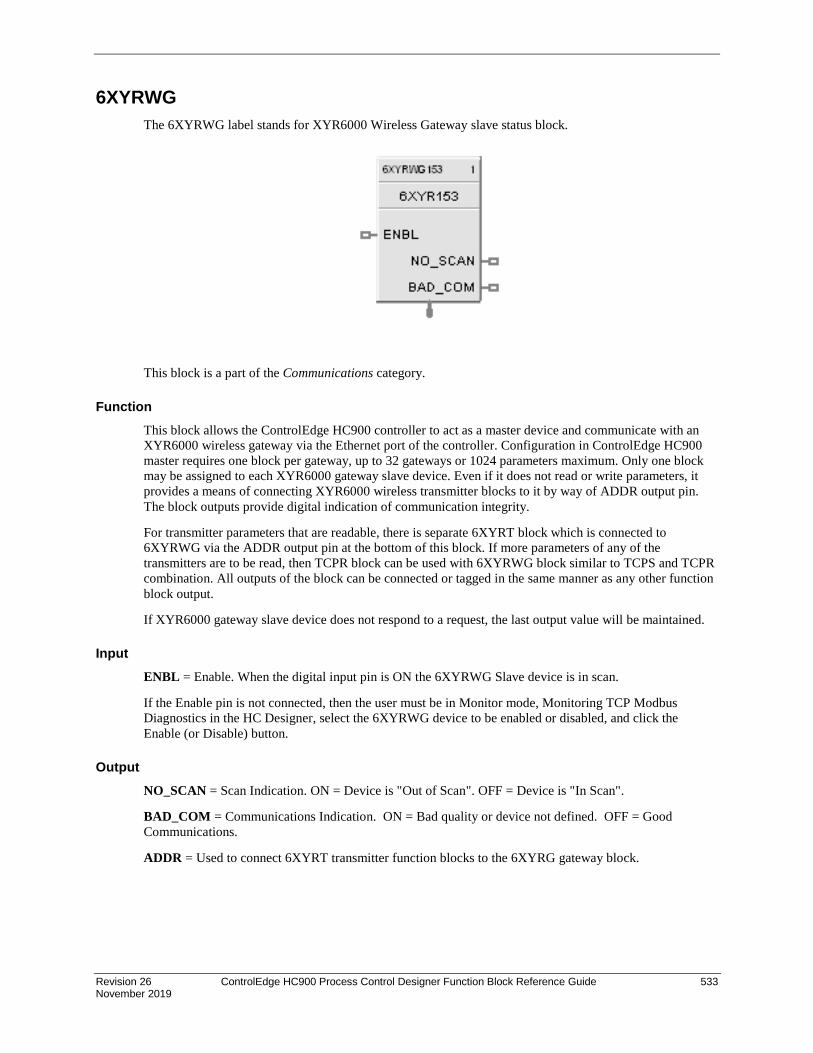
Revision 26 ControlEdge HC900 Process Control Designer Function Block Reference Guide 533 November 2019
6XYRWG The 6XYRWG label stands for XYR6000 Wireless Gateway slave status block.
This block is a part of the Communications category.
Function This block allows the ControlEdge HC900 controller to act as a master device and communicate with an XYR6000 wireless gateway via the Ethernet port of the controller. Configuration in ControlEdge HC900 master requires one block per gateway, up to 32 gateways or 1024 parameters maximum. Only one block may be assigned to each XYR6000 gateway slave device. Even if it does not read or write parameters, it provides a means of connecting XYR6000 wireless transmitter blocks to it by way of ADDR output pin. The block outputs provide digital indication of communication integrity.
For transmitter parameters that are readable, there is separate 6XYRT block which is connected to 6XYRWG via the ADDR output pin at the bottom of this block. If more parameters of any of the transmitters are to be read, then TCPR block can be used with 6XYRWG block similar to TCPS and TCPR combination. All outputs of the block can be connected or tagged in the same manner as any other function block output.
If XYR6000 gateway slave device does not respond to a request, the last output value will be maintained.
Input ENBL = Enable. When the digital input pin is ON the 6XYRWG Slave device is in scan.
If the Enable pin is not connected, then the user must be in Monitor mode, Monitoring TCP Modbus Diagnostics in the HC Designer, select the 6XYRWG device to be enabled or disabled, and click the Enable (or Disable) button.
Output NO_SCAN = Scan Indication. ON = Device is "Out of Scan". OFF = Device is "In Scan".
BAD_COM = Communications Indication. ON = Bad quality or device not defined. OFF = Good Communications.
ADDR = Used to connect 6XYRT transmitter function blocks to the 6XYRG gateway block.

534 ControlEdge HC900 Process Control Designer Function Block Reference Guide Revision 26 November 2019
Configurable Parameters Properties Group Parameter Index # Parameter Description Value or Selection
Configure Modbus Slave Tag Name
0 Description of 6XYRWG slave device
16 character tag name (ASCII characters only).
Slave address and Tag Name must be unique within a control file.
Modbus/TCP address
1 IP Address of XYR6000 Wireless gateway device on the link.
Enter unique address. (Cannot be 0.0.0.0 or 255.255.255.255)
Default IP address = 0.0.0.0 which means 6XYRWG slave will NOT be in scan.
Modbus Double Register Format
Each IEEE 32-bit floating point number requires two consecutive registers (four bytes) starting with the register defined as the starting register for the information. The stuffing order of the bytes into the two registers differs among Modbus hosts. The selections are:
Selection Description Byte order
FP B Floating Point Big Endian Format (recommended format) 4, 3, 2, 1
FP BB Floating Point Big Endian with byte-swapped 3, 4, 1, 2
FP L Floating Point Little Endian Format 1, 2, 3, 4
FP LB Floating Point Little Endian with byte-swapped 2, 1, 4, 3
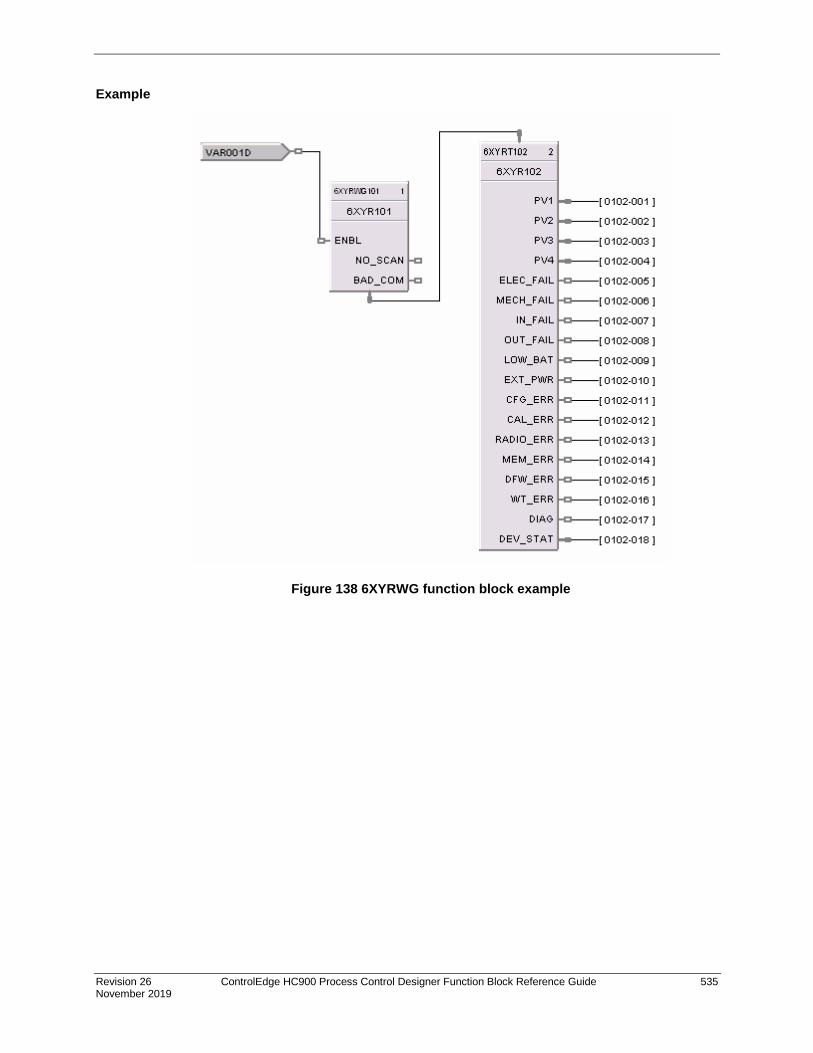
Revision 26 ControlEdge HC900 Process Control Designer Function Block Reference Guide 535 November 2019
Example
Figure 138 6XYRWG function block example

For more information To learn more about ControlEdge HC900, visit www.honeywellprocess.com Or contact your Honeywell Account Manager
Process Solutions Honeywell
1250 W Sam Houston Pkwy S Houston, USA, TX 77042
Honeywell Control Systems Ltd Honeywell House, Skimped Hill Lane Bracknell, England, RG12 1EB
51-52-25-109 Rev.26 November 2019 2019 Honeywell International Inc.
Shanghai City Centre, 100 Jungi Road Shanghai, China 20061
www.honeywellprocess.com
Sales and Service For application assistance, current specifications, ordering, pricing, and name of the nearest Authorized Distributor, contact one of the offices below
ASIA PACIFIC Honeywell Process Solutions, Phone: + 800 12026455 or +44 (0) 1202645583 (TAC) [email protected] Australia Honeywell Limited Phone: +(61) 7-3846 1255 FAX: +(61) 7-3840 6481 Toll Free 1300-36-39-36 Toll Free Fax: 1300-36-04-70 China – PRC - Shanghai Honeywell China Inc. Phone: (86-21) 5257-4568 Fax: (86-21) 6237-2826 Singapore Honeywell Pte Ltd. Phone: +(65) 6580 3278 Fax: +(65) 6445-3033 South Korea Honeywell Korea Co Ltd Phone: +(822) 799 6114 Fax: +(822) 792 9015
EMEA Honeywell Process Solutions, Phone: + 800 12026455 or +44 (0) 1202645583 Email: (Sales) [email protected] or (TAC) [email protected]
AMERICAS Honeywell Process Solutions, Phone: (TAC) (800) 423-9883 or (215) 641-3610 (Sales) 1-800-343-0228 Email: (Sales) [email protected] or (TAC) [email protected]
Specifications are subject to change without notice.