controledge hc900 controller redundancy …...iv controledge hc900 controller redundancy overview...
TRANSCRIPT

Honeywell Process Solutions
ControlEdge HC900 Controller Redundancy
Overview & System Operation
Doc. No.: 51-52-25-133 Revision: 11 Date: November 2019

ii ControlEdge HC900 Controller Redundancy Overview & System Operation Revision 11 November 2019
Notices and Trademarks
Copyright 2019 by Honeywell Revision 11, November 2019
Warranty/Remedy Honeywell warrants goods of its manufacture as being free of defective materials and faulty workmanship. Contact your local sales office for warranty information. If warranted goods are returned to Honeywell during the period of coverage, Honeywell will repair or replace without charge those items it finds defective. The foregoing is Buyer's sole remedy and is in lieu of all other warranties, expressed or implied, including those of merchantability and fitness for a particular purpose. Specifications may change without notice. The information we supply is believed to be accurate and reliable as of this printing. However, we assume no responsibility for its use.
While we provide application assistance personally, through our literature and the Honeywell web site, it is up to the customer to determine the suitability of the product in the application.
Honeywell Process Solutions 1250 W Sam Houston Pkwy S
Houston, TX 77042
Honeywell is a U.S. registered trademark of Honeywell
Other brand or product names are trademarks of their respective owners.

Revision 11 ControlEdge HC900 Controller Redundancy Overview & System Operation iii November 2019
About This Document
Abstract This manual gives an overview of the ControlEdge HC900 Redundancy architecture and products.
References The following list identifies all documents that may be sources of reference material for topics discussed in this publication.
Document Title Doc ID
ControlEdge HC900 Controller Specification 51-52-03-31
ControlEdge HC900 Module Specification 51-52-03-41
Process Control Designer Specification 51-52-03-43
ControlEdge HC900 Controlware Specification 51-52-03-42
ControlEdge HC900 Process & Safety Controller User and Installation Manual
51-52-25-154
ControlEdge HC900 Controller Designer User Guide 51-52-25-110
ControlEdge HC900 Controller Utilities User Guide 51-52-25-126
ControlEdge HC900 Controller Designer Function Block Reference Guide 51-52-25-109
ControlEdge HC900 Controller Communications User Guide 51-52-25-111
900 Control Station User Guide 51-52-25-148
900 Station Designer Software UG 51-52-25-149
ControlEdge HC900 Controller System Safety Manual 51-52-25-153
Revision Information
Document Name
51-52-25-133 ControlEdge HC900 Controller Redundancy Manual
Revision Number Publication Date
Seattle updates 4 December 2013 Redundancy updates 5 June 2014 SafetyWrite updates 6 June 2015
Updated with 12 racks and 100ms cycle support 7 Mar 2015 Updated with fiber optic specification 8 Apr 2017
Updated with function blocks, name change 9 April 2018 Inclusion of Ring topology architecture 10 December 2018
Added Redundant I/O Module Replacement section 11 November 2019

Contents
iv ControlEdge HC900 Controller Redundancy Overview & System Operation Revision 11 November 2019
Support & Contact Information For Europe, Asia Pacific, North and South America contact details, refer to the back page of this manual or the appropriate Honeywell Solution Support web site:
Honeywell Organization WWW Address (URL)
Corporate http://www.honeywell.com
Honeywell Process Solutions http://www.hpsweb.honewell.com/ps
HPS Technical tips http://hpsweb.honeywell.com/Cultures/en-US/Products/Instrumentation/hybrid/hc900/TechnicalTips/documents.htm
Telephone and Email Contacts
Area Organization Phone Number
United States and Canada Honeywell Inc.
1-800-343-0228 Customer Service
1-800-423-9883 Global Technical Support
Global Email Support Honeywell Process Solutions
Email: (Sales) [email protected] or (TAC) [email protected]

Contents
Revision 11 ControlEdge HC900 Controller Redundancy System Operation & Overview Summary v November 2019
Symbol Definitions The following table lists those symbols that may be used in this document to denote certain conditions.
Symbol Definition
This DANGER symbol indicates an imminently hazardous situation, which, if not avoided, will result in death or serious injury.
This WARNING symbol indicates a potentially hazardous situation, which, if not avoided, could result in death or serious injury.
This CAUTION symbol may be present on Control Product instrumentation and literature. If present on a product, the user must consult the appropriate part of the accompanying product literature for more information.
This CAUTION symbol indicates a potentially hazardous situation, which, if not avoided, may result in property damage.
WARNING PERSONAL INJURY: Risk of electrical shock. This symbol warns the user of a potential shock hazard where HAZARDOUS LIVE voltages greater than 30 Vrms, 42.4 Vpeak, or 60 Vdc may be accessible. Failure to comply with these instructions could result in death or serious injury.
ATTENTION, Electrostatic Discharge (ESD) hazards. Observe precautions for handling electrostatic sensitive devices
Protective Earth (PE) terminal. Provided for connection of the protective earth (green or green/yellow) supply system conductor.
Functional earth terminal. Used for non-safety purposes such as noise immunity improvement. NOTE: This connection shall be bonded to protective earth at the source of supply in accordance with national local electrical code requirements.
Earth Ground. Functional earth connection. NOTE: This connection shall be bonded to Protective earth at the source of supply in accordance with national and local electrical code requirements.
Chassis Ground. Identifies a connection to the chassis or frame of the equipment shall be bonded to Protective Earth at the source of supply in accordance with national and local electrical code requirements.

Contents
vi ControlEdge HC900 Controller Redundancy Overview & System Operation Revision 11 November 2019
This page has been intentionally left blank
Contents
Revision 11 ControlEdge HC900 Controller Redundancy System Operation & Overview Summary vii November 2019
Contents
Introduction ..................................................................................................................... 1
Overview ......................................................................................................................... 1
Purpose of this document ................................................................................................ 1
What’s in this document .................................................................................................. 1
Documentation ................................................................................................................ 1
Purpose of the product .................................................................................................... 2
Product architecture ........................................................................................................ 2
Key components ............................................................................................................. 4
Redundant Controller Rack ............................................................................................. 4
CPU ................................................................................................................................. 5
Power .............................................................................................................................. 5
Redundant Switch Module (RSM) ................................................................................... 5
Remote I/O Racks ........................................................................................................... 6
Dual-Port Scanner2 Module ............................................................................................ 6
Power Status Module ...................................................................................................... 6
I/O Modules ..................................................................................................................... 7
Operator Interfaces & Serial Ports .................................................................................. 7
Networking ...................................................................................................................... 8
System Network .............................................................................................................. 8
System Network Supervisory Functions ........................................................................ 11
To PC Applications ........................................................................................................ 11
To Peer ControlEdge HC900 Controllers ...................................................................... 11
Connection options........................................................................................................ 12
I/O Network to Remote Racks ....................................................................................... 14
Device Network (Serial) ................................................................................................. 15
Modbus Master ............................................................................................................. 15
Modbus Slave ............................................................................................................... 15
Modbus Master and/or Slave ........................................................................................ 15
Remote Access ............................................................................................................. 15
Configuration ................................................................................................................. 16
Lead Controller configuration ........................................................................................ 16
Contents
viii ControlEdge HC900 Controller Redundancy Overview & System Operation Revision 11 November 2019
Configuration & Setup Parameters for Redundant Controllers ...................................... 16
Reserve Controller configuration ................................................................................... 16
Software ........................................................................................................................ 17
HC Designer & HC Utilities PC Software ....................................................................... 17
Downloading configuration from PC to controller .......................................................... 17
Configuration storage .................................................................................................... 18
Configuration edits ........................................................................................................ 18
Uploading configuration from controller to PC ............................................................... 18
Downloading to multiple controllers ............................................................................... 18
Configuration backup .................................................................................................... 18
Configuration conversion ............................................................................................... 18
Monitoring configurations .............................................................................................. 19
Operation ...................................................................................................................... 20
Overview ....................................................................................................................... 20
Start-Up ......................................................................................................................... 20
Modes of operation........................................................................................................ 20
RUN Mode (Locked) ...................................................................................................... 21
RUN/PROGRAM Mode (Unlocked) ............................................................................... 21
PROGRAM Mode (Locked) ........................................................................................... 21
Steady State Operations ............................................................................................... 22
Execution time ............................................................................................................... 22
Execution sequence ...................................................................................................... 22
Lead/Reserve controller synchronization ...................................................................... 23
Failover ......................................................................................................................... 24
Automatic Failover......................................................................................................... 24
Manual Failover ............................................................................................................. 24
Failover Performance .................................................................................................... 24
Redundancy Diagnostic Monitoring ............................................................................... 24
IO Module Redundancy ................................................................................................. 25
Overview ....................................................................................................................... 25
Installation ..................................................................................................................... 26
Installing the Redundant Controller Rack ...................................................................... 26

Contents
Revision 11 ControlEdge HC900 Controller Redundancy System Operation & Overview Summary ix November 2019
Installing the I/O Racks ................................................................................................. 26
Installing Networking Equipment ................................................................................... 27
I/O Network ................................................................................................................... 27
Supervisory / Peer Network ........................................................................................... 27
Installing a Panel-Mounted Operator Interface .............................................................. 27
3rd Party Panel-Mounted OI .......................................................................................... 27
Installing PC Hosts ........................................................................................................ 28
Honeywell HC Designer & HC Utilities Software ........................................................... 28
Honeywell Experion Software ....................................................................................... 28
3rd Party PC Application Software ................................................................................ 28
Troubleshooting ............................................................................................................ 29
Diagnostic Indicators ..................................................................................................... 29
Diagnostic Monitoring from HC Designer and HC Utilities PC Software........................ 29
Status data available via Supervisory PC ...................................................................... 29
Troubleshooting ............................................................................................................ 30
Servicing ....................................................................................................................... 33
Module Replacement .................................................................................................... 33
C75 Module Replacement ............................................................................................. 33
Redundancy Switch Module Replacement .................................................................... 33
Scanner2 Module Replacement .................................................................................... 33
C75/C75S Power Supply Replacement ......................................................................... 33
Non-Redundant Power Supply for I/O Rack Replacement ............................................ 34
Optional Redundant Power Supply for I/O Rack Replacement ..................................... 34
Power Status Module Replacement .............................................................................. 34
I/O Module Replacement ............................................................................................... 34
Redundant I/O Module Replacement ............................................................................ 35
UPGRADING FIRMWARE ............................................................................................ 36
Controller Firmware Upgrade ........................................................................................ 36
Getting Started .............................................................................................................. 36
Program Mode .............................................................................................................. 37
Download procedure ..................................................................................................... 37
Failure Modes ............................................................................................................... 38

Contents
x ControlEdge HC900 Controller Redundancy Overview & System Operation Revision 11 November 2019
Error Messages ............................................................................................................. 38
Scanner Firmware Upgrade .......................................................................................... 39
Getting Started .............................................................................................................. 39
Program Mode .............................................................................................................. 39
Utilities Program ............................................................................................................ 40
Download procedure ..................................................................................................... 40
Failure Modes ............................................................................................................... 40
Error Messages ............................................................................................................. 41
Contents
Revision 11 ControlEdge HC900 Controller Redundancy System Operation & Overview Summary xi November 2019
Figures Figure 1 - ControlEdge HC900 Redundant Controller architecture (Star topology) ..................................................... 2 Figure 2 - ControlEdge HC900 Redundant Controller Architecture (Ring topology) ................................................... 3 Figure 3 Redundant controller rack components ........................................................................................................... 4 Figure 4 Ethernet switch with redundant controller....................................................................................................... 9 Figure 5 Ethernet switches with dual networks ........................................................................................................... 10 Figure 6 Peer Data Exchange, Redundant Controllers, Non-Redundant Network ..................................................... 12 Figure 7 Peer Data Exchange, Redundant Controllers, Non-Redundant Network ..................................................... 13 Figure 8 Peer Data Exchange, Redundant Controllers, Dual Networks ..................................................................... 14 Figure 9 Connection from Lead controller to PC ........................................................................................................ 17 Figure 10 Modes of operation on RSM ....................................................................................................................... 21 Figure 11 Lead/Controller synchronization ................................................................................................................. 23 Figure 12 Connecting UIO Terminal to RTP Using Pre-Fabricated Cable ................................................................. 25


Revision 11 ControlEdge HC900 Controller Redundancy Overview & System Operation 1 November 2019
Introduction
Overview
Purpose of this document Provide an overview of the Redundant ControlEdge HC900 product.
What’s in this document • Unless stated otherwise references to process only models C30, C50, C70, C75, S50 & S75 also
apply to process safety models C30S, C50S, C70S, C75S, S50S, S75S. All controllers and their scanner modules in a system must use the same basic model process or safety/process.
Documentation See References on page iii.
Purpose of the product Documentation
Revision 11 ControlEdge HC900 Controller Redundancy Overview & System Operation 2 November 2019
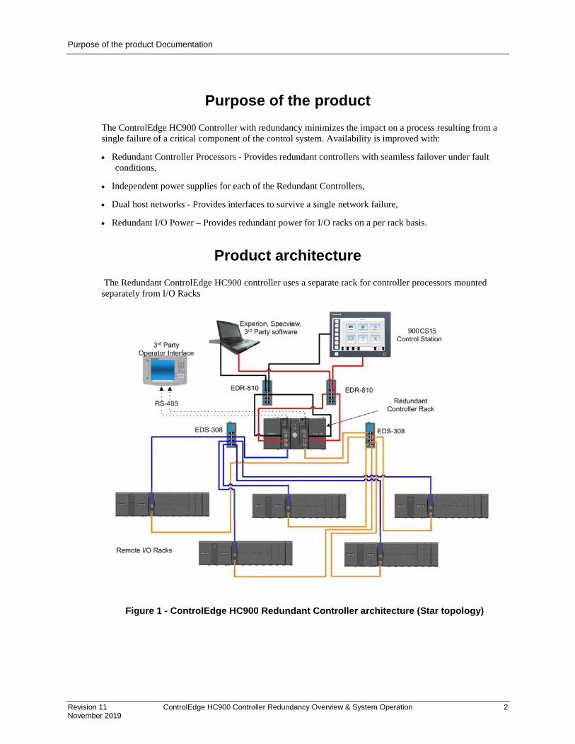
Purpose of the product The ControlEdge HC900 Controller with redundancy minimizes the impact on a process resulting from a single failure of a critical component of the control system. Availability is improved with:
• Redundant Controller Processors - Provides redundant controllers with seamless failover under fault conditions,
• Independent power supplies for each of the Redundant Controllers,
• Dual host networks - Provides interfaces to survive a single network failure,
• Redundant I/O Power – Provides redundant power for I/O racks on a per rack basis.
Product architecture The Redundant ControlEdge HC900 controller uses a separate rack for controller processors mounted separately from I/O Racks
Figure 1 - ControlEdge HC900 Redundant Controller architecture (Star topology)

Product architecture Documentation
Revision 11 ControlEdge HC900 Controller Redundancy Overview & System Operation 3 November 2019
Figure 2 - ControlEdge HC900 Redundant Controller Architecture (Ring topology)
Key components Redundant Controller Rack
4 ControlEdge HC900 Controller Redundancy Overview & System Operation Revision 11
November 2019
Key components
Redundant Controller Rack
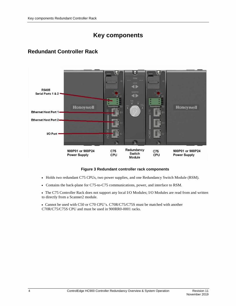
Figure 3 Redundant controller rack components
• Holds two redundant C75 CPUs, two power supplies, and one Redundancy Switch Module (RSM).
• Contains the back-plane for C75-to-C75 communications, power, and interface to RSM.
• The C75 Controller Rack does not support any local I/O Modules; I/O Modules are read from and written to directly from a Scanner2 module.
• Cannot be used with C50 or C70 CPU’s. C70R/C75/C75S must be matched with another C70R/C75/C75S CPU and must be used in 900RR0-0001 racks.

Key components Redundant Controller Rack
Revision 11 ControlEdge HC900 Controller Redundancy Overview & System Operation 5 November 2019
CPU • Requires Scanner2 module(s)
• Reads inputs from I/O Racks through Scanner2 modules
• Executes control strategy (function blocks)
• Writes outputs to I/O Racks through Scanner2 modules
• Dual Ethernet communication ports to host systems. It is good engineering practice to isolate the control network, E1 and E2 ports, from unknown Ethernet traffic to ensure robust reliable communications with a properly configured firewall such as the MOXA EDR-810.
• Each C75 Controller CPU has a dedicated, single Ethernet communication port to I/O racks
• Two RS485 serial ports – Modbus or ELN protocols for interface to OI, Modbus Host, or Modbus Slaves
• Lead Controller CPU – writes to the physical outputs; serves as the single external interface to other devices and systems (i.e., responds to requests from PC Hosts, a local Operator Interface, communicates to ControlEdge HC900 peers, and polls network slave devices)
• Reserve Controller CPU – executes control strategy in sync with Lead but does not write to physical outputs; does not respond to Hosts or OI.
• Reserve Controller CPU receives configuration updates and run-time data (operator entries, supervisory changes) from the Lead CPU with no manual user interaction. Configuration changes to a Reserve CPU are not permitted, except through the Lead CPU where both CPUs receive the change.
• The C75 is not recommended for non-redundant applications.
• C75 non-SIL models MUST BE matched with non-SIL Scanner2s.
• C75S SIL models MUST BE matched with SIL Scanner2s S75.
Power • Each C75 CPU has a dedicated Power Supply (two in the controller rack). Failure of the Lead CPU
power supply will cause a failover condition.
• CPU's prior to Version 6 require 900P02 power supplies for use in the redundant controller rack. If no longer available, use 900P01 with Ferrite Filter (p/n: 51197612-001, Fair Rite p/n: 0443164151 or equal) on incoming power cable
• Each power supply should be powered from a separate circuit protected mains.
Redundant Switch Module (RSM) • One RSM is installed in the redundant controller rack.
• Provides indicators to identify Lead and Reserve Controller CPU’s.
• Provides a key switch to set the controller mode (RUN, PROGRAM, RUN/PROG), and to force a manual failover from the Lead to the Reserve. The Reserve CPU tracks the mode selection of the Lead CPU.
• RSM may be replaced under power.
Key components Remote I/O Racks
6 ControlEdge HC900 Controller Redundancy Overview & System Operation Revision 11
November 2019
Remote I/O Racks • Each CPU has a separate Ethernet 100base T physical connection for up to 12 Remote I/O racks.
• Racks are available in three sizes: 4 I/O modules, 8 I/O modules, 12 I/O modules
• Systems with only one remote rack may have the remote rack connected directly to the CPU without a switching hub.
• Systems with more than one remote rack require a separate switching hub for each CPU connection. The switching hubs used in the I/O network must be Honeywell recommended industrial grade hubs. The I/O network must be considered a private network with no other Ethernet traffic permitted to ensure stable reliable communications.
• Remote racks require a dual-ported Scanner2 module to interface with the Redundant Controllers.
• Remote racks hold one Scanner2 module, one power supply, and up to 4, 8, or 12 I/O modules.
• The 8 and 12 Slot racks are available with a redundant power supply option. A Power Status Module (PSM) provides power supply status when two power supplies are used.
• The PSM monitors the power supply outputs and turns the green status LED off if a fault is detected.
• The load is distributed between the two supplies during normal operation when two power supplies are used.
• Racks with four I/O slots do not support the redundant power option.
Dual-Port Scanner2 Module • Reads inputs from the modules in the rack.
• Writes outputs to the modules in the rack.
• Has two Ethernet ports – one dedicated to each of the redundant C75 Controller CPU’s
• Maintains communications with both Lead and Reserve C75 CPU’s to facilitate failover.
• One Scanner2 Module is installed in each I/O Rack
• Required for the interface to C75 redundant controllers (cannot use non-redundant Scanner modules with C75 CPUs)
• S75 Scanner2s must be used with C75 Controllers. S75S Scanner2s must be used with C75S controllers.
• Scanner2 modules may be replaced under power - User to take proper precautions, Note IO will move to Failsafe values.
Power Status Module • Indicates current status of both Power Supplies
• May be replaced under power

Key components Operator Interfaces & Serial Ports
Revision 11 ControlEdge HC900 Controller Redundancy Overview & System Operation 7 November 2019
I/O Modules
CAUTION: For I/O redundancy, prefabricated cable length from RTP to Redundant UIO modules must be same.
• The full complement of ControlEdge HC900 Analog and Digital I/O modules are available for use in I/O racks using the Scanner2 module connected to redundant C75 Controller CPU’s.
• Any module may be inserted into any rack slot location.
• Redundant UIO modules are supported in the ControlEdge HC900 system.
• I/O modules may be replaced under power- user to take proper precautions (Refer “Redundant I/O Module Replacement”).
Operator Interfaces & Serial Ports • The C75 CPU provides two RS 485 serial ports.
• Only one Honeywell Control Station may be connected to a controller.
• Lead controller communicates with the operator interface.
• Baud rates of 1200 to 115K are supported for communications to the Operator Interfaces for distances up to 2000 feet, 610M.
• The RS 485 twisted pair cable should be connected from the interface to each C75 CPUs of a redundant system to maintain communication following a failover event.
• The same serial port (S1 or S2) must be used on both CPUs of a redundant system to maintain compatibility with the common configuration.
• Failure of a lead CPU will cause the reserve CPU to assume the serial port function.
• Failure of a serial port of the Lead controller will not cause a failure of the CPU.
• The S1 and S2 serial ports may also be used to interface the controller to 3rd party operator interfaces using RS 485 and Modbus RTU slave protocol.

Networking System Network
8 ControlEdge HC900 Controller Redundancy Overview & System Operation Revision 11
November 2019
Networking
System Network Each C75 CPU provides two 10/100base T Ethernet Host ports with Modbus TCP protocol. A total of 10 sockets are available and are shared by the two ports of the CPU for host device interfacing. Either port may be used in a non-redundant connection for host systems that do not support redundant network communications.
Note: It is good engineering practice to isolate the control network, E1 and E2 ports, from unknown Ethernet traffic to ensure robust reliable communications with a properly configured firewall such as the MOXA EDR-810
• Requires Honeywell (PN 50008930-001) or commercially available industrial switches, routers, etc for 10/100-baseT connection to the host/peer network. See Figure 4.
• Supports single or dual network interface to PC Hosts. E1 and E2 ports must be configured for separate subnets.
• Supports single or dual network interface to peer ControlEdge HC900 Redundant Controllers.
• Supports single network interface to peer ControlEdge HC900 Non-Redundant Controllers or other Modbus/TCP devices.
• Network changes such as setting IP addresses must be made with the controller in the Program mode. See Modes of operation on page 20.
• Maximum distance of system network (per 10/100 baseT specification, 100 meters per segment).
• Host devices or Managed switches (if used) must be configured to Auto Negotiate (speed and duplex).

Networking System Network
Revision 11 ControlEdge HC900 Controller Redundancy Overview & System Operation 9 November 2019
Figure 4 Ethernet switch with redundant controller
Networking System Network
10 ControlEdge HC900 Controller Redundancy Overview & System Operation Revision 11
November 2019
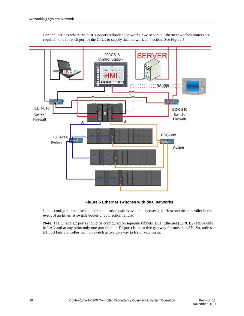
For applications where the host supports redundant networks, two separate Ethernet switches/routers are required, one for each port of the CPUs to supply dual network connection. See Figure 5.
Figure 5 Ethernet switches with dual networks
In this configuration, a second communication path is available between the Host and the controller in the event of an Ethernet switch /router or connection failure.
Note: The E1 and E2 ports should be configured on separate subnets. Dual Ethernet (E1 & E2) active only in LAN and at any point only one port (default E1 port) is the active gateway for outside LAN. So, unless E1 port fails controller will not switch active gateway to E2 or vice versa.

Networking System Network Supervisory Functions
Revision 11 ControlEdge HC900 Controller Redundancy Overview & System Operation 11 November 2019
System Network Supervisory Functions
To PC Applications Network communications of a host system to the controller is directed to the Lead controller. Communication to the Reserve controller is not supported. Following a failover event, the new Lead controller assumes this function.
• Native Applications – HC Designer & HC Utilities
− Communicate to ControlEdge HC900 Controllers over Ethernet
− Applications provide a choice of either a single port to verify proper port operation, or two ports with automatic connection where the PC will use the first available port capable of communicating to the controller.
• OPC Client Applications - Honeywell’s Matrikon OPC server is a PC application with an embedded communication driver to support simplex and dual network communications to ControlEdge HC900 controllers and other Modbus/TCP compatible devices. The database export files generated by Process Control Designer software may be used to transfer the database from the controller to the application, minimizing the amount of user entered data needed to apply the application. The OPC server is used to interface products such as Experion and Specview to ControlEdge HC900 controllers with dual Ethernet capability.
• Supports single or dual network interface to C75 CPUs
• Communicate to Honeywell Experion Software
• Communicate to 3rd Party OPC-Client aware PC applications
− Communicate to ControlEdge HC900 Controllers over Ethernet
− OPC server detects a failure of an Ethernet connection and automatically fails-over to a second port.
• Communication READ from safety worksheet is permitted in the RUN mode.
• Communications WRITES into the safety configuration is NOT permitted in the RUN mode.
• Communication WRITE into the safety worksheet is possible by enabling variables on the Safety worksheet for Non-Critical Safety functions by writing to a WVAR function block on the process worksheet assigned to the non-critical safety variable on the safety worksheet.
• Communication WRITES into the safety worksheet must be restricted to non-safety critical functions only.
To Peer ControlEdge HC900 Controllers • Peer-to-Peer communications to C30, C50, C70 or other C75 Controllers
• All peer controllers must be on same subnet.
• Lead Controller handles all peer communications
• C70 and C75 peers will switch E1/E2 networks to support peer communications (assumes no non-redundant peers)
• Automatic failover of function to the new Lead Controller
• Auto-Discovery of peer network addresses; Easy to configure & set-up
• Peer controllers do not consume Ethernet sockets.
• A controller can support up to 32 peers in its configuration database.
Networking System Network Supervisory Functions
12 ControlEdge HC900 Controller Redundancy Overview & System Operation Revision 11
November 2019
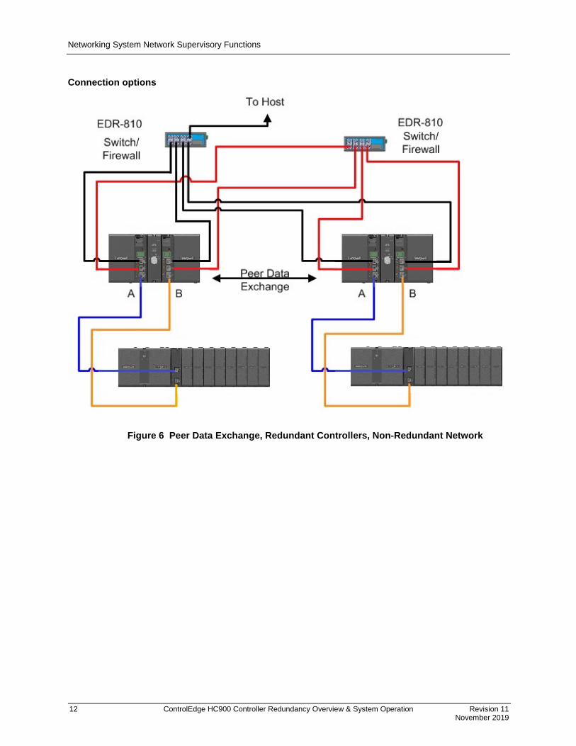
Connection options
Figure 6 Peer Data Exchange, Redundant Controllers, Non-Redundant Network

Networking System Network Supervisory Functions
Revision 11 ControlEdge HC900 Controller Redundancy Overview & System Operation 13 November 2019
Figure 7 Peer Data Exchange, Redundant Controllers, Non-Redundant Network

Networking I/O Network to Remote Racks
14 ControlEdge HC900 Controller Redundancy Overview & System Operation Revision 11
November 2019
Figure 8 Peer Data Exchange, Redundant Controllers, Dual Networks
I/O Network to Remote Racks • IEEE 802.4 Physical Layer Ethernet
• Two networks must be used for the I/O rack connections in a redundant system, one for each C75 CPU. See Figure 1.
• May be direct connected for single I/O rack systems.
• Two Ethernet switches must also be used for installations with 2 or more I/O racks
• Must use Honeywell recommended industrial grade switches (PN 50008930-001). Performance of the system is not warranted if an alternate switch is used for this connection.
• Up to 12 I/O Racks per configuration
• Separate Ethernet switch required for interface from each C75 CPU
• Requires Ethernet cable: Shielded CAT5 cable with RJ-45 connectors.
Networking Device Network (Serial)
Revision 11 ControlEdge HC900 Controller Redundancy Overview & System Operation 15 November 2019
Device Network (Serial)
Modbus Master • RS-485 Serial Interface with Modbus RTU Protocol
• Two ports available, each can be set as a Master or Slave.
• Only one of the two ports may be selected for Modbus RTU Master operation.
− The same port on each CPU must be used for this function to maintain consistency between controller configurations.
− Both CPUs of the redundant controller should be connected to the slave devices.
• Up to 32 Slave Devices supported per configuration.
• Up to 1024 total slave register addresses supported per configuration.
Modbus Slave • The two serial ports of the C75 CPU may each be set to RS-485 and Modbus slave operation.
• Supports data exchange with an external Modbus master such as a local operator panel or PC application.
• Port connections to redundant C75 CPUs should be made to both CPUs in the rack.
• Uses same local Modbus unit address for both RS-485 serial ports of the two C75 CPUs.
• A modem configuration selection extends the 3-character timeout limit of Modbus protocol for remote access.
Modbus Master and/or Slave • Lead Controller transmits on the link.
• Automatic failover of Master/Slave functions to the new Lead Controller.
• Failure of the Modbus Master serial port of the Lead Controller will not cause a failover of the CPU.
• Supports transmission speeds from 1200 to 115200 baud.
• Up to 609 Meters, 2000 feet, total network length
Remote Access • Requires an external modem.
• Available with HC Designer software.
• Lead Controller provides communications.

Configuration Lead Controller configuration
16 ControlEdge HC900 Controller Redundancy Overview & System Operation Revision 11
November 2019
Configuration
Lead Controller configuration • Develop the initial control strategy or convert C30, C50 or C70 configurations.
• Make incremental changes to existing control strategies as required.
• Upload & Download a control strategy from the PC.
Configuration & Setup Parameters for Redundant Controllers • Upon initial power-up, prior to configuration, either CPU may be assigned Lead status by the system.
• Configurations are loaded into a Lead Controller only.
• The PC is connected to the Lead Controller as viewed from the indicators on the Redundant Switch Module (RSM).
• All controller data needed for synchronization between the Lead and Reserve Controllers is automatically transferred; no user-programming required.
• Single or Dual (Supervisory) Network interfaces available, no selection required.
Reserve Controller configuration • Lead and Reserve firmware must be the same revision level.
• Controller configurations loaded into the Lead Controller are automatically transferred to the Reserve Controller.
• The Reserve Controller’s status indicator on the RSM is illuminated when database synchronization exists.
• Powering a Reserve CPU with an on-line Lead Controller will trigger the Lead to reprogram the Reserve.
• If both CPUs of a redundant controller are being powered with valid configurations, but only one has the desired configuration, the CPU with the desired configuration should be powered first.

Configuration Software
Revision 11 ControlEdge HC900 Controller Redundancy Overview & System Operation 17 November 2019
Figure 9 Connection from Lead controller to PC
Software
HC Designer & HC Utilities PC Software • The version number of the software should be equal to or greater than the version number of the
controller CPU being configured.
• The same software is used to configure both redundant and non-redundant ControlEdge HC900 controllers.
• Supports forward migration of existing C30, C50, C70 and C70R configurations to the C75.
Downloading configuration from PC to controller • Downloading configurations to a Lead Controller can be performed using a serial port or a network port.
• The Lead Controller has two Ethernet ports, each supplied with a default IP address from the Honeywell factory.
− Ethernet Port #1 (E1) is supplied with IP address 192.168.1.254 and Ethernet Port #2 (E2) is supplied with IP address 192.168.2.254. Users should change the default addresses to make them compatible with their local network(s). Each port must be configured for a separate subnet.
− IP addresses entered into the Lead Controller are automatically transferred to the Reserve Controller.
• The Reserve Controller does not communicate on a network.
− If the Reserve Controller transitions to become a Lead Controller in a system, it assumes the network communication function for the control system.

Configuration Software
18 ControlEdge HC900 Controller Redundancy Overview & System Operation Revision 11
November 2019
Configuration storage • Controller configurations downloaded to the controller are stored in battery backed RAM memory and
non-volatile Flash memory.
− The controller CPU executes its program from RAM memory. The battery backed RAM memory also stores the controller dynamic status during a loss of power to allow graceful resumption of controller operation following the interruption. If the battery is not available, startup following a power loss will use the configuration stored in Flash memory.
Configuration edits • On-line edits to the configuration may be downloaded to the controller.
− On-line edits made to C75 CPU configurations are stored in both RAM and Flash memory.
− HC Designer software lets you monitor the controller’s live configuration to verify edits. All edits are made to the configuration of the Lead controller. The Reserve controller’s configuration is automatically updated following a change to the Lead controller’s configuration.
Uploading configuration from controller to PC • Controller configurations may be uploaded from the controller’s RAM memory, and may include a
user‘s annotations, eliminating the risk of selecting an inappropriate file from the PC’s memory for editing when making changes to a running controller. Upload requests are serviced by the Lead Controller.
Downloading to multiple controllers • Controller configuration files ending with extension .cde do not include serial port and network port
setups.
− This facilitates downloading the same configuration file to multiple controllers on the same network or serial link without creating network address duplications or bus contention problems.
− Require the port parameters to be manually entered as a separate task while HC Designer is in communication with the controller.
Configuration backup • Controller configurations may be uploaded and saved as Backup Files.
− Backup files contain all of the information needed to restore a CPU to the operating conditions at the time the backup file was created, eliminating the need to for separate manual entries.
− Useful facility to quickly get a controller back on-line following CPU replacement.
− Backup configuration files use file extension .cbk.
Configuration conversion • Configurations built for use with C30, C50, C70 or C70R CPUs may be saved and downloaded into C75
CPUs following a file conversion performed using the appropriate version of HC Designer software.
− To convert C30, C50, C70 or C70R configuration files for used with C75 CPUs, open the files to be converted using HC Designer and perform a “Save As” operation and select a C75 file type.

Configuration Software
Revision 11 ControlEdge HC900 Controller Redundancy Overview & System Operation 19 November 2019
Monitoring configurations • Monitoring the configuration of the Lead Controller may be performed using Process Control Designer
software.
• Controller connection via Ethernet or serial.
• When Ethernet is used, HC Designer consumes one network socket.
• While in the monitor mode, viewing the function block diagram allows the user to view the input and output values for each function block.
• Watch windows allow viewing data by parameter type and in a user specified group.
• System Monitor (ASYS) function blocks provide an output to indicate the Reserve status of the CPU.
• Redundant controller status may be monitored from HC Designer.
• A redundancy icon is provided to allow access to information in the monitor menu.
• Selections under the Utilities Tab allow users to view diagnostic status and perform maintenance level activities.
• Redundancy Status (RSTAT) block provides additional monitoring and failover input pin. Adding the RSTAT block to an existing configuration requires a COLD START.

Operation Overview
20 ControlEdge HC900 Controller Redundancy Overview & System Operation Revision 11
November 2019
Operation
Overview In a redundant ControlEdge HC900 system, the Lead Controller performs all primary tasks including interfacing with remote I/O racks, communicating with a local HMI, exchanging data with peer controllers, interfacing with Modbus slave devices, and communicating with a Host PC application. Detection of a fault or removing power from a Reserve Controller will initiate a diagnostic prompt in the Lead Controller, but will have no impact on the process under control. The detection of a fault or removing power from a Lead Controller will initiate failover, that is, transfer all primary tasks to the available Reserve Controller, establishing this controller as the new Lead. Following a failover, the new Lead Controller will remain the Lead, even if the condition that caused the failover is corrected.
Start-Up • Assignment of Lead and Reserve status is determined at start-up
− First available C75 assumes Lead
− In case of a tie, CPU mounted in the left position of the rack will Lead
− No user configuration or manual operations required to establish Lead / Reserve status
• Lead Controller assumes control of I/O and all external communication interfaces.
• Reserve Controller receives the configuration from the Lead Controller
Modes of operation The modes of operation are:
• Run This is also the SAFE mode for SIL Controllers.
• Run/Program
• Program
You can change modes with:
• key-switch on the redundancy control module
• HC Designer software
• HC Utilities software
• a command from a supervisory host (address 0000h, bit 6)
• with a rising edge on the ^FOVER pin of the RSTAT function block
Both Lead and Reserve Controllers maintain the same mode. Placing the Lead Controller into the Program mode will also place the Reserve Controller in the Program mode.
Operation Modes of operation
Revision 11 ControlEdge HC900 Controller Redundancy Overview & System Operation 21 November 2019
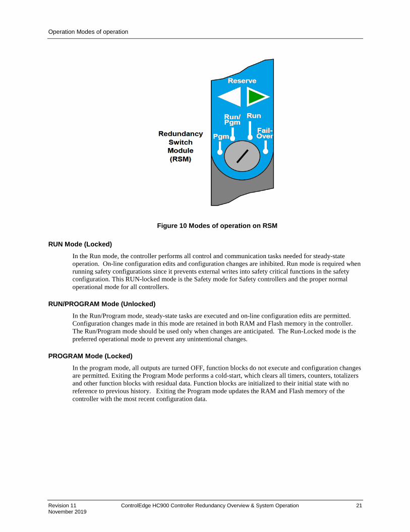
Figure 10 Modes of operation on RSM
RUN Mode (Locked) In the Run mode, the controller performs all control and communication tasks needed for steady-state operation. On-line configuration edits and configuration changes are inhibited. Run mode is required when running safety configurations since it prevents external writes into safety critical functions in the safety configuration. This RUN-locked mode is the Safety mode for Safety controllers and the proper normal operational mode for all controllers.
RUN/PROGRAM Mode (Unlocked) In the Run/Program mode, steady-state tasks are executed and on-line configuration edits are permitted. Configuration changes made in this mode are retained in both RAM and Flash memory in the controller. The Run/Program mode should be used only when changes are anticipated. The Run-Locked mode is the preferred operational mode to prevent any unintentional changes.
PROGRAM Mode (Locked) In the program mode, all outputs are turned OFF, function blocks do not execute and configuration changes are permitted. Exiting the Program Mode performs a cold-start, which clears all timers, counters, totalizers and other function blocks with residual data. Function blocks are initialized to their initial state with no reference to previous history. Exiting the Program mode updates the RAM and Flash memory of the controller with the most recent configuration data.

Operation Steady State Operations
22 ControlEdge HC900 Controller Redundancy Overview & System Operation Revision 11
November 2019
Steady State Operations • Lead Controller issues polls to I/O Racks for inputs
• Both Lead and Reserve read I/O responses from I/O Racks
• Lead and Reserve both execute function blocks in the control strategy
• Only the Lead Controller writes physical outputs to the I/O Racks
• Lead Controller responds to communication messages from host devices on the Supervisory Network and RS-485 interfaces
• Lead Controller handles communications with ControlEdge HC900 peers
• Lead Controller handles communications with Modbus RTU slave devices
• Lead and Reserve exchange system status data to determine conditions for failover.
• I/O Scanners relay system status data between each Controller to determine conditions for failover
Execution time ControlEdge HC900 Controllers are designed to execute control functions within fixed scan cycles for analog data types and logic data types. In redundant controllers, the minimum scan time is 100ms for analog data types and 25ms for logic data types; scan time varies depending on configuration.
Execution sequence • The type of control functions executed during a scan is determined by the system configuration.
− Controller configurations contain a series of algorithms in the form of function blocks that get executed in a fixed sequence. The first 100 function blocks are pre-assigned by the system to handle communication tasks, alarm processing, system monitoring functions, etc. and cannot be changed by the user. Starting with function block number 101, the user may select the type of function to be executed.
• The sequence of function block execution is initially determined by the sequence in which the function blocks are placed on the graphic diagram in HC Designer.
− Final desired sequence must be set by the user to achieve proper and optimum performance.
− Incorrect execution sequences can contribute to delays in processing outputs and/or improper or unexpected operation.
• The ControlEdge HC900 controller samples all inputs before the start of a controller scan.
− Each input being used in the configuration must be assigned to a function block. The sequence order of the function block determines when in time the actual value will be updated. It is important that algorithms that need updated input values for their calculations have the inputs execute first in the sequence.
• Except for Time Proportioning Output (TPO), Three-Position-Step-Control (TPSC) and Position Proportional Output (PPO) function block types that update their physical output values while the function blocks are being executed, all physical outputs are updated at the end of a scan.

Operation Steady State Operations
Revision 11 ControlEdge HC900 Controller Redundancy Overview & System Operation 23 November 2019
Lead/Reserve controller synchronization • Lead Controller automatically synchronizes the Reserve with the configuration database
− During download of a configuration from a Host to the Lead
− During process operation to bring a Reserve Controller from the Unavailable state to the On-Line state
• Lead Controller automatically synchronizes the Reserve with run-time data during each function block execution cycle
• Both the Lead and Reserve Controllers execute the function blocks in the control strategy, but only the Lead Controller writes the physical outputs to the I/O Racks. See Figure 11.
• The Lead and Reserve controllers exchange system status to determine conditions for failover.
Figure 11 Lead/Controller synchronization
Get Inputs
SYNC
Control SYNCExecute Control Strategy
Control SYNCExecute Control Strategy
Write Outputs
Diagnostic Check
Communications
Get Inputs
SYNC
Control SYNCExecute Control Strategy
Control SYNCExecute Control Strategy
Diagnostic Check
Lead Controller Reserve Controller
Operation Failover
24 ControlEdge HC900 Controller Redundancy Overview & System Operation Revision 11
November 2019
Failover
Automatic Failover • Triggered on any of the following conditions of the Lead Controller:
− Loss of communications with I/O Rack(s) than Reserves communication with IO Racks. (i.e. Reserve has greater IO rack communication).
− Processor exception conditions
• Error conditions that occur in the following areas will not cause a failover:
− Loss of communications to a Host on a network
− Loss of communications to Modbus Slave devices
− Loss of communications to Operator Interface
− Loss of communications with a Peer controller
• During the transition from the Lead to the Reserve, analog and digital output status is maintained at the I/O racks.
Manual Failover • Via Key Switch on the Redundancy Switch Module in the Redundant Controller Rack
• Via Software Command from HC Designer & HC Utilities PC Software
• Via Software Command from Modbus / TCP & Serial Modbus RTU Hosts
• Via command from RSTAT Function Block
Failover Performance Failure condition detection and failover from Lead to Reserve CPU executed in 4 analog control cycles or less.
Redundancy Diagnostic Monitoring • From HC Designer and HC Utilities PC Software
− Redundant System Status - current status of Lead/Reserve Controller CPU’s
− On-Line Monitoring, Controller Diagnostics, Communications Loop-Back tests
− Redundant Link Status – status of communications between Lead and Reserve controllers.
− Lead CPU status
− Reserve CPU status
− Scanner status
Operation IO Module Redundancy
Revision 11 ControlEdge HC900 Controller Redundancy Overview & System Operation 25 November 2019
IO Module Redundancy
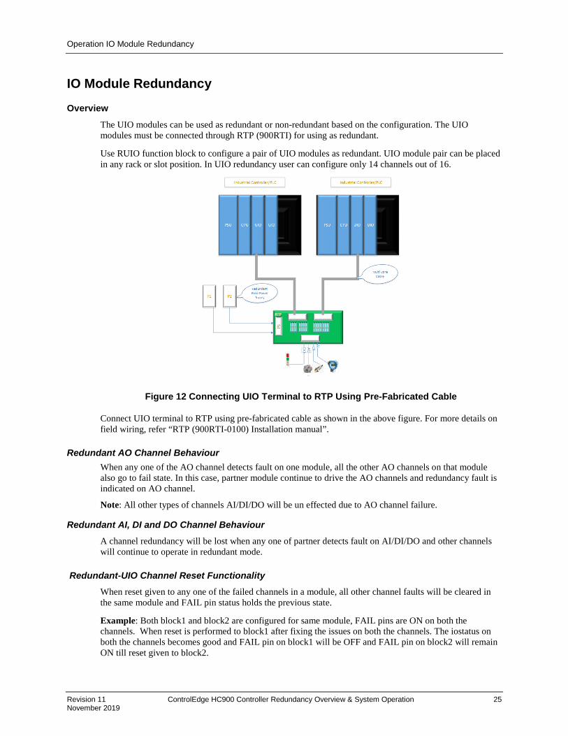
Overview The UIO modules can be used as redundant or non-redundant based on the configuration. The UIO modules must be connected through RTP (900RTI) for using as redundant.
Use RUIO function block to configure a pair of UIO modules as redundant. UIO module pair can be placed in any rack or slot position. In UIO redundancy user can configure only 14 channels out of 16.
Figure 12 Connecting UIO Terminal to RTP Using Pre-Fabricated Cable
Connect UIO terminal to RTP using pre-fabricated cable as shown in the above figure. For more details on field wiring, refer “RTP (900RTI-0100) Installation manual”.
Redundant AO Channel Behaviour When any one of the AO channel detects fault on one module, all the other AO channels on that module also go to fail state. In this case, partner module continue to drive the AO channels and redundancy fault is indicated on AO channel.
Note: All other types of channels AI/DI/DO will be un effected due to AO channel failure.
Redundant AI, DI and DO Channel Behaviour
A channel redundancy will be lost when any one of partner detects fault on AI/DI/DO and other channels will continue to operate in redundant mode.
Redundant-UIO Channel Reset Functionality When reset given to any one of the failed channels in a module, all other channel faults will be cleared in the same module and FAIL pin status holds the previous state.
Example: Both block1 and block2 are configured for same module, FAIL pins are ON on both the channels. When reset is performed to block1 after fixing the issues on both the channels. The iostatus on both the channels becomes good and FAIL pin on block1 will be OFF and FAIL pin on block2 will remain ON till reset given to block2.

Installation Installing the Redundant Controller Rack
26 ControlEdge HC900 Controller Redundancy Overview & System Operation Revision 11
November 2019
Installation
Installing the Redundant Controller Rack • Rack must be installed in an enclosure and oriented for ventilation with mounting holes on top and
bottom
• A Redundancy Switch Module (RSM) mounts in the center slot of the rack
• One Power Supply and C75 Controller mount to the left of the RSM
• One Power Supply and C75 Controller mount to the right of the RSM
• Ethernet ports (E1 & E2) are host network ports
• Ethernet port (labeled I/O) is the dedicated I/O rack port
• Power with over-current protection and separate disconnects should be connected to each Power Supply
• Isolating the C75 controller Ethernet ports with properly configured firewall such as MOXA EDR-810 provides additional network integrity.
Installing the I/O Racks • Rack must be installed in an enclosure and oriented for ventilation with mounting holes at top and
bottom of rack
• When installing a single Power Supply in the rack:
− The Power Supply mounts in the first slot on the left in the rack.
• When installing redundant Power Supplies in the proper rack to support this feature:
− Mount the Power Status Module (PSM) to the left of the first power supply.
− The second Power Supply installs to the left of the PSM.
• A Scanner2 CPU mounts to the right of the Power Supply.
• I/O Modules mount to the right of the Scanner2 module.
• Power with over-current protection and separate disconnects should be connected to each Power Supply.

Installation Installing Networking Equipment
Revision 11 ControlEdge HC900 Controller Redundancy Overview & System Operation 27 November 2019
Installing Networking Equipment
I/O Network • Required for configurations using multiple I/O Racks; Not required for configurations using only one
I/O Rack.
• Must use Honeywell qualified industrial un-managed Ethernet switches between controller rack and I/O Racks
• Follow installation instructions in ControlEdge HC900 Controller Installation and User Guide 51-52-25-154.
• Use a separate un-managed Ethernet switch for each C75 Controller CPU.
• Each Scanner2 connects to both un-managed Ethernet switches using consistent port assignments for each I/O rack.
• Only use Shielded CAT 5 cable for network connections.
Supervisory / Peer Network • Any Ethernet switching device that meets the specifications for the specific site can be used.
• Follow the supplier’s installation instructions
• Each C75 CPU connects to each switching device
• Use consistent C75 port assignments when connecting the CPUs to their respective switching devices.
• Only use shielded CAT5 cable for Supervisory/Peer Network connections.
Installing a Panel-Mounted Operator Interface
3rd Party Panel-Mounted OI • Follow the supplier’s installation instructions
• The RS-485 Serial Interface is Daisy-chained to both C75 Controllers
• Use the same serial port, S1 or S2 on both C75 CPUs.

Installation Installing PC Hosts
28 ControlEdge HC900 Controller Redundancy Overview & System Operation Revision 11
November 2019
Installing PC Hosts
Honeywell HC Designer & HC Utilities Software • Operating Systems supported: Win 7, 8 & 10 Professional (32 and 64 bit)
• PC hardware requirements (minimum):
− Pentium Class 1.2 Ghz with minimum 1 GB of RAM (minimum)
− Screen resolution – SVGA (1024x768 recommended) or better
− CD ROM drive (for loading software)
• Connects to the C75/C75S Controllers using Ethernet, USB to RS-485 converter or Modbus RTU
• Available on CD
Honeywell Experion Software • See document EP03-050-430 Experion HS Specification
• Connects to the C75/C75S Controllers using Ethernet
• Interfaced through Honeywell-supplied OPC Server for redundant networks or embedded drive
• For simplex connections
3rd Party PC Application Software • Interfaced through Honeywell Matrikon OPC Server
• Requires 3rd Party PC Software to be an OPC Client
• Connect to the C75/C75S Controllers using Ethernet
• OPC Server available on CD
Troubleshooting Diagnostic Indicators
Revision 11 ControlEdge HC900 Controller Redundancy Overview & System Operation 29 November 2019
Troubleshooting
Diagnostic Indicators • LEDs on the front of each module are provided to indicate the module’s health. These include:
− C75/C75S Controller Status LEDs
− Scanner2 Status LEDs
− I/O Module Status LEDs
• The ControlEdge HC900 modules use a combination of color and flashing patterns to indicate fault conditions and the type of fault detected. See the ControlEdge HC900 controller manual for a detailed explanation of fault conditions.
• LEDs on the front of the Redundancy Switch Module indicate the Lead/Reserve status of the two redundant C75/C75S controllers
− Reserve indicator will flash while Reserve CPU is being updated by Lead.
− Reserve controller is not available during this flashing period.
• LEDs on the front of the Power Status Module indicate the status of the redundant Power Supplies for an I/O Rack
− ON if the power supply if functioning properly
− Off if either the 5 volt or the 24 volt source of a power supply has a fault.
ATTENTION:
With: Reserve CPU; Unsynchronized database error,
• if current lead shuts down, system will fail to back up CPU and likely see an I/O bump during transition.
• if power to Lead is lost combined with a fault then Lead will not likely failover.
Diagnostic Monitoring from HC Designer and HC Utilities PC Software • Monitor the current status of Lead/Reserve Controller CPU’s
• View a Historical log of controller failover events
• Monitor Lead controller function block execution
• View controller diagnostic status
• Perform communications Loop-Back tests
Status data available via Supervisory PC • Current status of Lead/Reserve Controller CPU’s
• Status of I/O Rack Power, including optional redundant power supplies

Troubleshooting Troubleshooting
30 ControlEdge HC900 Controller Redundancy Overview & System Operation Revision 11
November 2019
Troubleshooting Note: This table assumes the system was properly commissioned and all devices and cabling were proven and only one failure existed prior to the failover occurrence. It also assumes Honeywell recommended I/O Switches are being used and all Ethernet cables are properly shielded.
Fault Condition On Previous Lead
Detection Method / Failover Trigger
Observable Indication after failover Corrective Action
User momentarily moves key RSM key switch to FAILOVER while in RUN or RUN/PROG
Lead detects switch in FAILOVER position
RSM arrow LEDs flip such that prior Reserve indicates it is now the Lead. The prior Lead will go through the transitions to synchronizing with the new Lead (flashing Reserve LED on the RSM) and then to ready Reserve (solid Reserve LED on the RSM).
None required.
Cable between Scanner2 and I/O Ethernet switch fails hard or intermittently
Lead determines that the Reserve can communicate to more scanner2's than it can
If the cable is in a failed state at the time of observation:
1. On Scanner2 module look at the port's upper LED associated with prior Lead. It will be off. This port's lower LED may or may not be off depending on the nature of the cable failure.
2. On the I/O Link Switch associated with the prior Lead look at port associated with the Scanner2. Both of this port's LEDs will be off.
1. Make sure cable is plugged into Scanner2
2. Make sure cable is plugged into network switch
3. Replace the cable
4. Make sure cable is properly shielded
Cable between I/O Ethernet switch and prior Lead fails hard or intermittently
Lead determines that the Reserve can communicate to more scanner2's than it can
If the cable is in a failed state at the time of observation:
1. On prior Lead look at the I/O port. Both of this port's LEDs will be off. If observed during the transition into the cable failure these LEDs will transition over a brief time from on to off.
2. On the I/O Link Switch associated with the prior Lead look at port associated with the C75/C70R. Both of this port's LEDs will be off.
1. Make sure cable is plugged into prior Lead
2. Make sure cable is plugged into network switch
3. Replace the cable
4. Make sure cable is properly shielded

Troubleshooting Troubleshooting
Revision 11 ControlEdge HC900 Controller Redundancy Overview & System Operation 31 November 2019
Lead I/O Ethernet switch power supply is hard-failed
Lead determines that the Reserve can communicate to more scanner2's than it can
On the I/O Link Switch associated with the prior Lead all of its LEDs will be off.
Apply power to this I/O Link Switch
Lead I/O Ethernet switch electronics failure
Lead determines that the Reserve can communicate to more scanner2's than it can
If the switch is in a failed state at the time of observation:
1. On this I/O Switch check the LEDs for abnormal activity
2. On each Scanner2 check the LEDs for abnormal activity
3. On the prior Lead check the LEDs for abnormal activity
1. Replace the Switch with a Honeywell recommended Switch
2. Check for and correct any improper grounding.
Lead I/O Ethernet switch is power cycled.
Lead determines that the Reserve can communicate to more scanner2's than it can
The I/O Link Switch associated with the prior Lead will show all its LEDs off while power is off and then should return to normal operations after power is re-applied (unless the switch was damaged during the power cycle)
1. Investigate why power was temporarily lost
2. Check that the switch is operating properly. Replace if it is not.
3. Check for and correct any improper grounding.
Scanner2's I/O port to prior Lead failed hard or intermittently.
Lead determines that the Reserve can communicate to more scanner2's than it can
If the port is in the failed state at the time of observation:
1. On Scanner2 module look at the port's LEDs associated with prior Lead. One or both should be off.
Replace the Scanner2 module
I/O port on the prior Lead failed hard or intermittently.
Lead determines that the Reserve can communicate to more scanner2's than it can
If the port is in the failed state at the time of observation:
1. On prior Lead look at the port's LEDs associated with prior Lead. One or both should be off.
Replace the prior Lead C75/C70R module
Lead C75/C75S lost power
Reserve is not receiving data messages from the Lead, AND
Reserve is not receiving any replies from any Scanner2's, AND
Reserve is not sensing the physical presence of the Lead
On RSM module both LEDs for the prior Lead Controller will be off and all LEDs will be off on the Lead Controller. The associated power supply module's LED will also be off.
Restore power to prior Lead C75/C75S
Troubleshooting Troubleshooting
32 ControlEdge HC900 Controller Redundancy Overview & System Operation Revision 11
November 2019
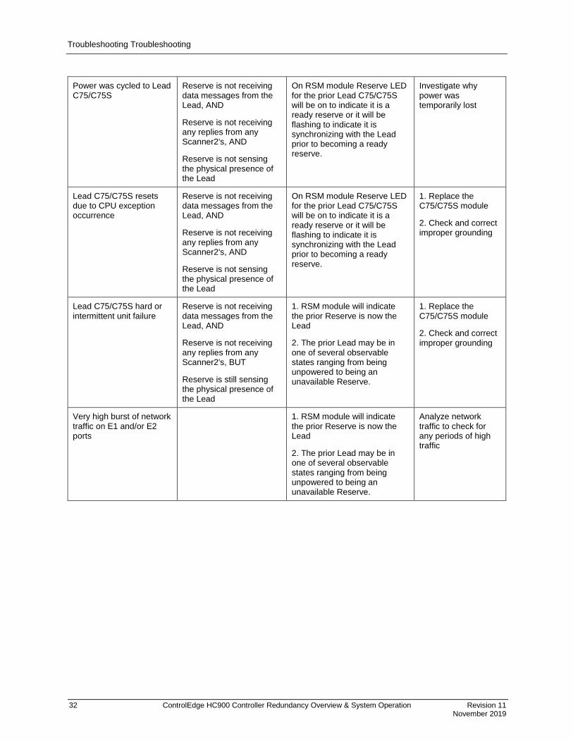
Power was cycled to Lead C75/C75S
Reserve is not receiving data messages from the Lead, AND
Reserve is not receiving any replies from any Scanner2's, AND
Reserve is not sensing the physical presence of the Lead
On RSM module Reserve LED for the prior Lead C75/C75S will be on to indicate it is a ready reserve or it will be flashing to indicate it is synchronizing with the Lead prior to becoming a ready reserve.
Investigate why power was temporarily lost
Lead C75/C75S resets due to CPU exception occurrence
Reserve is not receiving data messages from the Lead, AND
Reserve is not receiving any replies from any Scanner2's, AND
Reserve is not sensing the physical presence of the Lead
On RSM module Reserve LED for the prior Lead C75/C75S will be on to indicate it is a ready reserve or it will be flashing to indicate it is synchronizing with the Lead prior to becoming a ready reserve.
1. Replace the C75/C75S module
2. Check and correct improper grounding
Lead C75/C75S hard or intermittent unit failure
Reserve is not receiving data messages from the Lead, AND
Reserve is not receiving any replies from any Scanner2's, BUT
Reserve is still sensing the physical presence of the Lead
1. RSM module will indicate the prior Reserve is now the Lead
2. The prior Lead may be in one of several observable states ranging from being unpowered to being an unavailable Reserve.
1. Replace the C75/C75S module
2. Check and correct improper grounding
Very high burst of network traffic on E1 and/or E2 ports
1. RSM module will indicate the prior Reserve is now the Lead
2. The prior Lead may be in one of several observable states ranging from being unpowered to being an unavailable Reserve.
Analyze network traffic to check for any periods of high traffic

Servicing Troubleshooting
Revision 11 ControlEdge HC900 Controller Redundancy Overview & System Operation 33 November 2019
Servicing
Module Replacement • Servicing a failed module is accomplished by replacing only that module
C75 Module Replacement • Power for the module should be turned off during replacement.
• C75 model pairs must match C75 with C75 and S75 Scanner2; and C75S with C75S and S75S Scanner2.
• Replacement module must have same firmware revision
• Does not impact the other C75/C75S CPU module, which will continue to control the process
• Contains start-up diagnostics after replacement to verify proper operation
• If there is a Lead Controller, the configuration database is automatically copied from the Lead to the newly replaced C75/C75S CPU module.
• Both C75s must be the same firmware version.
Redundancy Switch Module Replacement • May be removed or inserted under power
• The C75/C75S CPU modules will remain in the last used mode while the Redundancy Switch Module is removed.
• Does not induce a controller failover during replacement
• C75 will not run the application when the RSM has failed and the unit undergoes a cold start.
Scanner2 Module Replacement • Scanner 2 Modules must agree with Controller type C75 with S75 and C75S with S75S.
• Power to the rack may remain on during module replacement when following proper safety and electrical regulations. Loss of communication to the IO rack will result in the IO modules going to the configured fail safe state.
• Caution field power may still be present on the IO modules.
• Redundant controllers will operate with the affected I/O in failsafe state during Scanner2 module replacement
• Does not impact other I/O Racks in the same configuration, unless configured to do so.
• Contains start-up diagnostics after replacement to verify proper operation
C75/C75S Power Supply Replacement • Requires power for the module to be turned off during replacement, which supplies power to a single
C75/C75S CPU
• Does not impact the Lead C75/C75S CPU module, which will continue to control the process
Servicing Troubleshooting
34 ControlEdge HC900 Controller Redundancy Overview & System Operation Revision 11
November 2019
Non-Redundant Power Supply for I/O Rack Replacement • Requires power for the module to be turned off during replacement, which supplies power to a single I/O
Rack
• IO may have power supplied through separate mains. Proper precautions and safety procedures must be followed.
Optional Redundant Power Supply for I/O Rack Replacement • Requires power for the module to be turned off during replacement
• Power is maintained for the I/O Rack by the other Power Supply of the redundant pair
• IO may have power supplied through separate mains. Proper precautions and safety procedures must be followed.
Power Status Module Replacement • May be removed or inserted under power
• No impact on the Scanner2 or I/O modules during replacement
I/O Module Replacement • May be removed or inserted under power
• Removable terminal blocks preserve field wiring during module replacement
• Removal of the module is detected by the Scanner2 and a diagnostic is posted
• Contains start-up diagnostics after replacement to verify proper operation

Servicing Troubleshooting
Revision 11 ControlEdge HC900 Controller Redundancy Overview & System Operation 35 November 2019
Redundant I/O Module Replacement In the redundant UIO configuration, de-energies the active AO channels before attempting to remove any Redundant UIO module, particularly in a system that is actively controlling a process.
De-energies the AO channel by performing the following options:
Option 1: Remove the field power supply from the module I/O terminals. (or)
Option 2: De-energies AO channel from the HCD utilities.
a. Open Designer Software.
b. Click Utilities tab (1).
c. In the Controller Utility Function, select Repair IO (2). The “Repair IO” dialog box appears.
d. Enter “RUIO Address” details in the Rack and Module columns and then click Force Shutdown.
Note: This operation can perform only in the normal mode (not in the monitor mode).
After I/O module replacement, perform RSTRT on channel block to get channel back in operation.

UPGRADING FIRMWARE Controller Firmware Upgrade
36 ControlEdge HC900 Controller Redundancy Overview & System Operation Revision 11
November 2019
UPGRADING FIRMWARE
Controller Firmware Upgrade
Getting Started Before you begin the firmware download there are a few things you need to be aware of:
1. PRIOR TO STARTING THE UPGRADE, THE PROCESS MUST BE TAKEN OFF-LINE. The code download procedure requires that the controller be put into the Program mode using the Keyswitch. In this mode, all outputs are forced to their off state.
2. Disable WI-FI on your PC, as it can interfere with firmware downloads.
3. Honeywell requires that you perform the CPU firmware upgrades individually by having only one of the CPUs powered at a time. Please note, both CPUs must be running the same version of software in order to operate as a redundant pair. A software version mismatch will prevent the reserve CPU from synchronizing with the lead.
4. Code Download can take from approximately 5 minutes using Ethernet; therefore, it is highly recommended that you do not start the code download procedure at a time when the likelihood of a power failure is increased, such as during thunderstorms.
5. The code download function is only available through the Utilities tab of the Hybrid Control Designer program or the Hybrid Control Utilities program. The upgrade is available via the controller Ethernet ports.
6. The controller will not allow the controller firmware download to begin if there is a low battery diagnostic on the CPU module.
7. Code download will clear the configuration database in the controller. Therefore, before code download is started, you must upload it into the Hybrid Control Designer and save it. Save As the appropriate model type and revision for which you are updating the firmware.
8. The upgrade files are distributed as a complete package and must reside in a unique subdirectory separate from any other previously distributed firmware upgrade files. Failure to comply could result in abnormal behavior when performing the upgrade.
9. If you are planning to upgrade the firmware in the Scanner2 Racks, complete the CPU upgrade first; then perform the scanner upgrade with only one of the CPUs powered. Follow the upgrade instructions provided with the new Scanner2 code.
Note: If starting with Firmware < 6.005 consult your vendor for update instructions.

UPGRADING FIRMWARE Controller Firmware Upgrade
Revision 11 ControlEdge HC900 Controller Redundancy Overview & System Operation 37 November 2019
Program Mode Before starting the Controller Firmware Download, make sure the controller is in the "Program Lock" mode or "Program mode". Note: A controller with software prior to version 4.000 must be in the "Program Lock" mode.
To enter "Program Lock" mode, turn the Mode Switch on the Redundancy Switch Module (RSM) counter-clockwise to the position labeled "Pgm".
To enter "Program" mode, use the "Set Controller Mode" function found in "Utilities" tab of the Hybrid Control Designer program or the Hybrid Control Utilities program. (This function no longer supported after firmware revision 6.005). Note: When programming the CPUs individually put the controller in the “Program Lock mode.
Download procedure Step 1: Backup the controller configuration as described in step 6 of GETTING STARTED above.
Step 2: Make sure the controller is in "Program Lock" or "Program" mode.
Step 3: Select the Utilities Worksheet tab on the HC Designer or Utilities.
Step 4: From the "Controller Utility Functions" select "Download to Controller". On the sub-menu, select
"Controller Firmware", then "Controller Module".
Step 5: Use the "Look in:" drop down list in the "Open" dialog box to select the drive and folder you placed
the files in.
Step 6: Select and open the file "C70Rv04_xxx.cpu" (or HC975v06_xxx.cpu or HC975SILv06_xxx.cpu)
displayed in the file list box.
Step 7: Select the "Port" and "Address" on the "Download File" dialog box.
Step 8: Click on the "Start" button in the "Download File" dialog box. The download will start, and
progress is displayed. The download itself will take several minutes.
Step 9: A "Download Succeeded" status will be displayed in the "Download File" dialog box. If a failure is
detected, an error message will appear in the Status section of the "Download File" dialog box. See "Error
Messages" for a list of possible messages and resolutions. Also see “Failure Modes”.
Step 10: Remove power from the CPU you just updated and apply power to the CPU not yet updated.
Leave the Mode switch in the “Program Lock” position. Repeat steps 2 through 9.
Step 11: Apply power to the CPU previously programmed
Step 12: Restore the configuration from the backup copy you previously made.
Step 13: Return the mode switch on the RSM to "Run" or "Run Lock" if "Program Lock" was used to do
the upgrade.
Step 14: Set Real Time Clock (RTC) via HC Designer/ Utilities (Utilities tab).

UPGRADING FIRMWARE Controller Firmware Upgrade
38 ControlEdge HC900 Controller Redundancy Overview & System Operation Revision 11
November 2019
Failure Modes If there is a download failure indication on the "Download File" dialog box:
o DO NOT cycle the controller power and DO NOT remove the battery.
o Check the physical connections.
o Check for power failures.
o Restart the download from the beginning.
Error Messages This is a list of possible error messages that could be displayed as the result of a Download Firmware failure:
Error Message What to do Instrument must be in PROGRAM LOCK mode to perform this operation
Put controller in program-lock mode before starting code download
Instrument's battery missing or dead Replace lead or reserve controller battery starting the code download.
Missing loader binary file Could not open the loader file. Make sure the “loader.s19” file is in the same directory as the firmware file to be downloaded.
Could not open firmware update file Make sure the firmware file is present in the directory selected.
Programming is not required; the downloaded version matches the code in the controller.
The version in the controller matches the version that was downloaded.
The downloaded file is corrupted The firmware file was bad. Replace the firmware file.
Failed to complete file transfer Could be caused by communication loss or controller power failure. Restart code download again.
Controller is not responding, code download failed Could be caused by communication loss or controller power failure. Restart code download again.
Failed to put instrument into loader transfer mode Could be caused by communication loss or controller power failure. Restart code download again.
Failed to get controller status Could be caused by communication| loss or controller power failure. Restart code download again.
Unexpected controller mode. Code download will abort. The controller will now reset
Could be caused by communication| loss or controller power failure. Restart code download again.
FLASH erase failure. Replace the controller card The controller has a hardware problem. Replace the controller card.
FLASH programming failure. Replace the controller card
The controller has a hardware problem. Replace the controller card.
FLASH memory failure. Replace the controller card The controller has a hardware problem. Replace the controller card.
An incomplete code download has been detected. Code download will proceed using the selected file
A previous code download was aborted or failed. Code download will proceed using the selected

UPGRADING FIRMWARE Scanner Firmware Upgrade
Revision 11 ControlEdge HC900 Controller Redundancy Overview & System Operation 39 November 2019
Scanner Firmware Upgrade
Getting Started Before you begin the download, there are a few things you need to be aware of:
1. PRIOR TO STARTING THE UPGRADE, THE PROCESS MUST BE TAKEN OFF-LINE.
The code download procedure requires that the controller be put into the Program mode. In this
mode, all outputs are forced to their off state.
2. Disable WI-FI on your PC, as it can interfere with firmware downloads.
3. All of the scanners in the system are upgraded in a single operation.
4. Code Download can take from approximately 5 minutes plus an additional 5 minutes per scanner
when using Ethernet. Therefore, it is highly recommended that you do not start the code download
procedure at a time when the likelihood of power failure is increased, such as during
thunderstorms.
5. The code download function is only available through the Utilities tab of the Hybrid Control
Designer program or the Hybrid Control Utilities program. The upgrade is available via the
controller Ethernet ports.
6. The controller will not allow the controller firmware download to begin if there is a low battery
diagnostic in either the lead or reserve.
7. Code download will clear the configuration database in the controller. Therefore, before code
download is started, you must upload it into the Hybrid Control Designer and save it. Save As the
appropriate model type and revision for which you are updating the firmware.
8. The upgrade files are distributed as a complete package and must reside in a unique subdirectory
separate from any other previously distributed firmware upgrade files. Failure to comply could
result in abnormal behavior when performing the upgrade.
Program Mode Before starting the Scanner2 Firmware Download, make sure the controller is in the "Program Lock" mode or "Program mode".
To enter "Program Lock" mode, turn the Mode Switch on the Redundancy Switch Module (RSM) counter-clockwise to the position labeled "Pgm".
To enter "Program" mode, use the "Set Controller Mode" function found in "Utilities" tab of the Hybrid Control Designer program or the Hybrid Control
UPGRADING FIRMWARE Utilities Program
40 ControlEdge HC900 Controller Redundancy Overview & System Operation Revision 11
November 2019
Utilities Program
Download procedure
Step 1: Backup the controller configuration as described in step 6 of GETTING STARTED above.
Step 2: Make sure the controller is in "Program Lock" or "Program" mode.
Step 3: Select the Utilities Worksheet tab on the HC Designer or Utilities.
Step 4: From the "Controller Utility Functions" select "Download to Controller". On the sub-menu, select
"Controller Firmware", then scanner Module".
Step 5: Use the "Look in:" drop down list in the "Open" dialog box to select the drive and folder you placed
the files in.
Step 6: Select and open the file "SCAN2v04_xxx.scn" (or SCANNER2v06_xxx.scn or
SCANNER2SILv06_xxx.scn) displayed in the file list box.
Step 7: Select the "Port" and "Address" on the "Download File" dialog box.
Step 8: Click on the "Start" button in the "Download File" dialog box. The download will start, and
progress is displayed. The download itself will take several minutes.
Step 9: "SUCCESS", "FAILED" or "MISSING" status will be displayed in the "Download File" dialog box
for each of the five possible scanners. If status of any of the scanners is "FAILED", see "Error Messages"
for a list of possible messages and resolutions. Also see “Failure Modes”. The same applies for any
scanners that are present but have a status of MISSING".
Step 10: Restore the configuration from the backup copy you previously made.
Step 11: Return the mode switch on the RSM to "Run" or "Run Lock" if "Program Lock" was used to do
the upgrade.
Failure Modes If there is a download failure indication on the "Download File" dialog box:
o DO NOT cycle the controller or scanner power and DO NOT remove the battery.
o Check the physical connections.
o Check for power failures.
o Restart the download from the beginning.

UPGRADING FIRMWARE Utilities Program
Revision 11 ControlEdge HC900 Controller Redundancy Overview & System Operation 41 November 2019
Error Messages This is a list of possible error messages that could be displayed as the result of a Download Firmware failure:
Error Message What to do
Instrument must be in PROGRAM LOCK mode to perform this operation mode before starting code
Put controller in program-lock mode before starting code download
Instrument's battery missing or dead Replace lead or reserve controller battery before starting the code download.
Missing loader binary file Could not open the loader file. Make sure the “loader.s19” file is in the same directory as the firmware file to be downloaded.
Could not open firmware update file Make sure the firmware file is present in the directory selected.
The downloaded file is corrupted The firmware file was bad. Replace the firmware file
Failed to complete file transfer Could be caused by communication loss or controller power failure. Restart code download again.
Controller is not responding, code download failed
Could be caused by communication loss or controller power failure. Restart code download again.
Failed to put instrument into loader transfer mode
Could be caused by communication| loss or controller power failure. Restart code download again.
Failed to get controller status Could be caused by communication loss or controller power failure. Restart code download again
Unexpected controller mode. Code download will abort. The controller will now reset
Could be caused by communication loss or controller power failure. Restart code download again.
An incomplete code download has been detected. Do not remove controller power! Removing controller power could result in damage to the scanner card(s)
A previous code download was aborted or failed. Code download will proceed using the selected file.
No scanner racks detected Most likely cause is no expansion racks connected to the main controller. It can also be caused by a scanner card failure. If a scanner is properly connected to the controller and this message is displayed, replace the scanner card.
“Rack 1: SUCCESS, Rack 2: FAILED" Completion report for scanner code download. There should be a SUCCESS status for each card connected to the main controller rack. A FAILED status could be caused by a communications problem between the main controller rack and the scanner racks or by a failed scanner

For more information To learn more about ControlEdge HC900, visit www.honeywellprocess.com Or contact your Honeywell Account Manager
Process Solutions Honeywell
1250 W Sam Houston Pkwy S Houston, USA, TX 77042
Honeywell Control Systems Ltd Honeywell House, Skimped Hill Lane Bracknell, England, RG12 1EB
51-52-25-133, Rev.11 November 2019 2019 Honeywell International Inc.
Shanghai City Centre, 100 Jungi Road Shanghai, China 20061 www.honeywellprocess.com
Sales and Service For application assistance, current specifications, pricing, or name of the nearest Authorized Distributor, contact one of the offices below.
ASIA PACIFIC Honeywell Process Solutions, (TAC) [email protected] Australia Honeywell Limited Phone: +(61) 7-3846 1255 FAX: +(61) 7-3840 6481 Toll Free 1300-36-39-36 Toll Free Fax: 1300-36-04-70 China – PRC - Shanghai Honeywell China Inc. Phone: (86-21) 5257-4568 Fax: (86-21) 6237-2826 Singapore Honeywell Pte Ltd. Phone: +(65) 6580 3278 Fax: +(65) 6445-3033 South Korea Honeywell Korea Co Ltd Phone: +(822) 799 6114 Fax: +(822) 792 9015
EMEA Honeywell Process Solutions, Phone: + 80012026455 or +44 (0)1344 656000 Email: (Sales) [email protected] or (TAC) [email protected]
Web
Knowledge Base search engine http://bit.ly/2N5Vldi
AMERICA’S Honeywell Process Solutions, Phone: (TAC) 1-800-423-9883 or 215/641-3610 (Sales) 1-800-343-0228 Email: (Sales) [email protected] or (TAC) [email protected] Web
Knowledge Base search engine http://bit.ly/2N5Vldi