hazelmere pyrolysis waste to energy plant
TRANSCRIPT

Hazelmere Pyrolysis Waste to
Energy Plant
Works Approval Application
Supporting Document
DRAFT
Prepared for
Eastern Metropolitan Regional Council
by Strategen December 2013


Hazelmere Pyrolysis Waste
to Energy Plant
Works Approval Application
Supporting Document
DRAFT
Strategen is a trading name of Strategen Environmental Consultants Pty Ltd Level 2, 322 Hay Street Subiaco WA ACN: 056 190 419 December 2013

Limitations
Scope of services
This report (“the report”) has been prepared by Strategen Environmental Consulting Pty Ltd (Strategen) in accordance
with the scope of services set out in the contract, or as otherwise agreed, between the Client and Strategen. In some
circumstances, a range of factors such as time, budget, access and/or site disturbance constraints may have limited the
scope of services. This report is strictly limited to the matters stated in it and is not to be read as extending, by
implication, to any other matter in connection with the matters addressed in it.
Reliance on data
In preparing the report, Strategen has relied upon data and other information provided by the Client and other
individuals and organisations, most of which are referred to in the report (“the data”). Except as otherwise expressly
stated in the report, Strategen has not verified the accuracy or completeness of the data. To the extent that the
statements, opinions, facts, information, conclusions and/or recommendations in the report (“conclusions”) are based in
whole or part on the data, those conclusions are contingent upon the accuracy and completeness of the data.
Strategen has also not attempted to determine whether any material matter has been omitted from the data. Strategen
will not be liable in relation to incorrect conclusions should any data, information or condition be incorrect or have been
concealed, withheld, misrepresented or otherwise not fully disclosed to Strategen. The making of any assumption does
not imply that Strategen has made any enquiry to verify the correctness of that assumption.
The report is based on conditions encountered and information received at the time of preparation of this report or the
time that site investigations were carried out. Strategen disclaims responsibility for any changes that may have
occurred after this time. This report and any legal issues arising from it are governed by and construed in accordance
with the law of Western Australia as at the date of this report.
Environmental conclusions
Within the limitations imposed by the scope of services, the preparation of this report has been undertaken and
performed in a professional manner, in accordance with generally accepted environmental consulting practices. No
other warranty, whether express or implied, is made.
Client: Eastern Metropolitan Regional Council
Report Version Revision
No. Purpose
Strategen author/reviewer
Submitted to Client
Form Date
Preliminary Draft Report A Client Review N. Zago/H. Ventriss electronic 19/12/13
Final Draft Report 0 Regulator review/ submission
N. Zago/P. Forster electronic 24/12/13
Final Report
Filename: EMR12223_01_R001_RevB4 - 24 December 2013

DRAFT Hazelmere Pyrolysis Waste to Energy Plant
EMR12223_01_R001_Rev0
24-Dec-13
Table of contents
1. Introduction 1
1.1 Project summary 1
1.2 Project justification 1
2. Administration 3
2.1 Applicant details 3
2.2 Premises details 3
2.2.1 Zoning 3
2.3 Prescribed premises category 5
2.4 Timing of construction and operation 6
2.5 Stakeholder consultation 6
2.6 Policy/guidance 7
3. Site environmental characteristics 8
3.1 Physical environment 8
3.1.1 Existing infrastructure 8
3.1.2 Climate 8
3.1.3 Topography 8
3.1.4 Soils and geology 8
3.1.5 Hydrology 8
3.1.6 Contaminated sites 9
3.2 Biological environment 9
3.2.1 Flora and vegetation 9
3.2.2 Fauna 10
3.3 Social environment 10
3.3.1 Sensitive receptors 10
3.3.2 Areas of significance 10
4. Design, construction and operation 12
4.1 Proposal characteristics 12
4.2 Process summary 12
4.3 Inputs and outputs 13
4.4 Project development and operations 13
4.5 Feed system 13
4.6 Pyrolysis unit 14
4.7 Gas cleanup 14
4.8 Bio-char output 15
4.9 Wastewater treatment 15
4.10 Thermal oxidiser 15
4.11 Gas engines 15
4.12 Utilities and plant services 16
4.13 Personnel 16
4.14 Procedural controls 16
4.15 Personal protective equipment control 16
5. Environmental management 17
5.1 Noise emissions 17
5.1.1 Sensitive receptors 17
5.1.2 Results 17
5.1.3 Noise monitoring 18
5.2 Dust emissions 19
5.2.1 Potential dust sources 19
5.2.2 Construction emissions 19
5.2.3 Operational emissions 19
5.2.4 Monitoring 19

DRAFT Hazelmere Pyrolysis Waste to Energy Plant
EMR12223_01_R001_Rev0
24-Dec-13
5.3 Air emissions 20
5.3.1 Emissions inventory 20
5.3.2 Emissions scenarios 21
5.3.3 Main stack emissions concentrations and WID limits 22
5.3.4 Gas engine exhaust emissions concentrations and WID limits 24
5.3.5 Background air quality data and assessment criteria 24
5.3.6 Dispersion modelling 28
5.3.7 Commissioning 38
5.3.8 Plume rise assessment 38
5.4 Odour emissions 40
5.5 Wastewater disposal 41
5.6 Groundwater management 41
5.6.1 Acid Sulphate Soils 41
5.6.2 Contamination 41
5.7 Fire risk 42
5.8 Traffic Management 42
5.8.1 Onsite traffic 42
5.8.2 Offsite traffic 42
6. Further information for EPA referral 43
6.1 Alignment with EPA recommendations (EPA Report 1468) 43
6.2 Significance test 46
7. References 48
List of tables
Table 1: Prescribed premises categories 5
Table 2: Schedule of construction 6
Table 3: Community consultation 6
Table 4: Groundwater quality 9
Table 5: Key characteristics table 12
Table 6: Operation specifications 13
Table 7: Wood chip typical analysis 13
Table 8: Kiln specifications 14
Table 9: Kiln products 14
Table 10: SACTO specifications 15
Table 11: Engine specifications 15
Table 12: Service specifications for natural gas 16
Table 13: Results of noise modelling (daytime; Mon-Sat 0700-1900) 17
Table 14: Results of noise modelling (evening; Mon-Sat 1900-2200) 18
Table 15: Emissions data for dispersion modelling 21
Table 16: Operating scenarios for air emissions assessment 21
Table 17: Comparison of emission concentrations and WID limits – bypass operation 23
Table 18: Air quality assessment criteria and background concentrations 26
Table 19: Maximum predicted GLCs at R2 – continuous operations 29
Table 20: Maximum predicted GLCs at R2 – reduced rate operations 31
Table 21: Maximum predicted GLCs at R2 – bypass operations 33
Table 22: Maximum predicted GLCs at R2 – cumulative impact assessment for continuous normal operations 35
Table 23: Maximum predicted GLCs at R2 – cumulative impact assessment for reduced rate operations 36
Table 24: Maximum predicted GLCs at R2 – cumulative impact assessment for bypass operations 37
Table 25: EPA recommendations for waste to energy technologies 43
Table 26: Significance test (EPA referral) 47

DRAFT Hazelmere Pyrolysis Waste to Energy Plant
EMR12223_01_R001_Rev0
24-Dec-13
List of figures
Figure 1: Site location 2
Figure 2: Metropolitan Region Scheme Zoning 4
Figure 3: Sensitive receptors 11
Figure 4: Contour plot of maximum predicted 1-hour average NO2 GLCs for normal operations 30
Figure 5: Contour plot of maximum predicted 1-hour average NO2 GLCs for reduced rate operations 32
Figure 6: Vertical velocity at plume centre vs height above ground level 39
Figure 7: Approach surfaces for Perth Airport runway 06/24 40
List of appendices
Appendix 1: Naturemap database search results
Appendix 2: Environmental Noise Assessment, Lloyd George Acoustics 2013
Appendix 3: Air emissions modelling, ENVIRON 2013


DRAFT Hazelmere Pyrolysis Waste to Energy Plant
EMR12223_01_R001_Rev0
24-Dec-13 1
1. Introduction
Eastern Metropolitan Regional Council (EMRC) proposes to develop the existing Hazelmere Recycling
Centre located approximately 14 km from the Perth, by installing a 3 MW Waste Wood to Energy (WWTE)
plant located on Part Lot 100 and Lot 201 Lakes Road, Hazelmere (Figure 1). The existing operation
recycles untreated timber (such as pallets and crates) into wood chip for sale and used mattresses into
their components for recycling. The WWTE plant would use part of the wood chip as the feed-source for
the plant.
1.1 Project summary
The WWTE plant will be based on pyrolysis technology developed by local company, Ansac, and their
parent company, Anergy, using a proven indirect-fired pyrolysis kiln to produce synthetic gas (syngas) for
use in gas engines for power generation. The process of pyrolysis involves heating organic materials
(wood chip in this case) to greater than 600˚C in the absence of oxygen. The EMRC project will use
shredded wood as the fuel source (such as pallets, crates, cable reels.) that would otherwise be disposed
to landfill. Resulting products are renewable electricity and bio-char (solid char of carbon and ash).
The proposal will result in air and noise emissions, the effects of both of which have been evaluated.
Other potential impacts will be associated with disposal of waste (solid and liquid), traffic management and
other amenity issues such as dust (i.e. from the production of bio-char). Management mechanisms will
include engineering controls, process design and monitoring.
1.2 Project justification
Waste minimisation is a priority for both State and Australian Governments. At Hazelmere, waste timber is
currently recovered and reprocessed into wood chip, wood chip fines, ecoChip mulch and coloured chip.
These products are sold for animal bedding and landscaping.
The 2012/2013 financial year saw 13 000 t of wood waste (untreated softwood timbers, packaging, pallets,
off-cuts and particleboard) diverted from landfill; 40 000 t of wood waste have been diverted from landfill
since the Hazelmere Recycling Centre was opened in 2008 (EMRC 2013a).
Currently, there is a large market for the wood chip fines and a smaller market for the wood chip. The use
of this wood chip as a fuel source for power generation is considered a beneficial way to ensure the wood
chip is utilised. By diverting this waste wood from landfill by using part of the wood chip for energy
generation, EMRC will reduce the greenhouse gas emissions that would otherwise be emitted from landfill,
generate renewable electricity and produce a potentially saleable bio-char product. The proposed WWTE
plant is intended to utilise chip derived from wood waste only; there is no intention to use trees for wood
chip for the purpose of electricity generation.
Reprocessing is ranked third out of seven preferred waste management options in the internationally-
recognised best practice waste management hierarchy, after reuse but above recycling (Waste Authority
2013). Energy recovery is a recognised option at the lower end of the waste hierarchy, being more
favourable than disposal to landfill, but less favourable than waste avoidance, reuse, reprocessing and
recovery options (Waste Authority 2013).
Ansac/Anergy technology has been developed at pilot scale over several years, and construction of the
Hazelmere WWTE plant will provide the opportunity to demonstrate new pyrolysis technology at a
commercial scale (Anergy 2013).
Australian Government endorsement of development of Waste to Energy technology is indicated by
provision of funding through the Clean Technology Innovation Fund, received by Ansac on the basis of
joint funding from the EMRC. This grant was awarded to Ansac in July 2013 and subsequently, a contract
was awarded to Ansac by the EMRC for the design and construction of the plant.

Figure 1 Site locationLegend
Site locationIndicative W TE plant locationRoads
STIR
LING
CR
BUSHMEAD RD
ROE
HWY
LAKES RD
TALBOT RD
GREAT EASTERN HWY BYPA
CLAYTON ST
VALE RD
WEST PDE
ARUM LILY PLMI
LITAR
Y RD
LLOY
D ST
CENT
RAL A
V
MARY
ST
WYNN
E ST
RAILWAY PDE
WATERHALL RD
COWIE CL
MONTREAL RD AMHERST RD
JANE
T ST
ROBE
RTSO
N ST
ELGEE RD
ERIC ST
WINGAT
E AV
HAZELMERE CRCS
CHRISTINA ST
FOUNDRY RDWALLSEND RD
ABER
NETH
Y RD
ANTHEA ST
CENT
ENNI
AL PL
WHITEMAN
RD
BILDJ
AR C
L
COPPERSHOP RD
PITT ST
WHITEHALL RD
KURRAT ELBRo
e Hwy
(Eas
t side
) PSP
GREAT EASTERN HWY BYPA
VALE
RD
ROE
HWY
404500
404500
405000
405000
405500
405500
406000
406000
406500
406500
6468
000
6468
000
6468
500
6468
500
6469
000
6469
000
6469
500
6469
500
6470
000
6470
000
6470
500
6470
500
6471
000
6471
000
Path: \\Gis -01\g is \Consult\2013\EM R\E MR12223_01\A rc M ap_docum ents\W or king\E M R12223_D001_Rev A _F 001.m xd
info@stratege n.co m.auww w.strate gen .c om .au
Sc ale at A4
Sourc e: M os aic:Landgate 2006; Roads : MRW A 2013.
Note that pos itional error s m ay occ ur in s om e areas
0 100 200 300 400 500Meters
1:15,000
Coor dinate S y stem : G DA 1994 MG A Zone 50
Date: 5 /11/2013Author: SF inn ing
¹!
!
!
!
!
!
!
!!
Es per anc eAlbany
Kununur ra
Port Hedland
Gera ld ton
Perth
Newm an
Kalgoorl ie
!
CavershamGuildford
HazelmerePerth Airport
Perth

DRAFT Hazelmere Pyrolysis Waste to Energy Plant
EMR12223_01_R001_Rev0
24-Dec-13 3
2. Administration
2.1 Applicant details
The applicant and occupier of the premises is:
Eastern Metropolitan Regional Council
1st Floor Ascot Place
226 Great Eastern Highway, Belmont, WA, 6104
Ph: (08) 9424 2222
Fax: (08) 9277 7598
Representative: Steve Fitzpatrick
2.2 Premises details
The site is located approximately 14 km north east of Perth, north of the Perth Airport in the suburb of
Hazelmere. Recycling of timber (such as pallets and wooden packaging and crates, off-cuts and cable
reels) and mattresses is undertaken at the site.
EMRC is currently in the process of planning the development of the EMRC Resource Recovery Park
(RRP) at Hazelmere, which is proposed to occupy Lots 201, 100 and potentially Lot 99(2) Lakes Road
bounded by Stirling Crescent and Bushmead Road. The RRP would include other waste management
processes in addition to the existing recycling of timber and mattresses, and the WWTP plant; appropriate
approvals will be sought for other elements of the RRP as planning is finalised.
This application only concerns the WWTE plant, which covers approximately 0.2 ha of the 10 ha RRP.
2.2.1 Zoning
The site is zoned ‘industrial’ under the Metropolitan Region Scheme (Figure 2) and ‘industrial development’
under the current Town Planning Scheme (TPS17). Adjacent lots to the west are zoned ‘rural’ under MRS
and ‘rural residential’ under TPS17. No re-zoning is anticipated for the Proposal; however, EMRC is
negotiating acquisition of Lot 99(2) immediately west of Lot 100 for inclusion of a community reuse,
recycling and drop-off centre for the RRP (approval for which is not being sought in this application).
The Hazelmere Enterprise Area Structure Plan (2011) outlines the potential future zoning changes that are
likely to be implemented; the site would remain an industrial area in the structure plan.

ROE HWY
STIR
LING
CR
BUSHMEAD RD
MIDLAND RDLAKES RD
WEST PDE
KALAMUNDA RD
TALBOT RD
GREAT EASTERN HWY BYPA
MILIT
ARY
RD
WATERHALL RD
ADELAIDE ST
ABER
NETH
Y RD
VALE RD
CLAYTON ST
HELENA VALLEY RD
CENT
RAL A
V
MARY
ST
WYNN
E ST
ADELAIDE ST WEST
IRWIN ST
BENSON WY
PEXTON DR ROBE
RTSO
N ST
WINGAT
E AV
HAZELMERE CRCS
HATCH CT
WUNDU ENT
ANTHEA ST
NOOY
AN CL
WHITEMAN
RD
NIRIMBA CL
LEWIS RD
GENTLE CIR
BOYD CL
TRIGG L
FLEET CIR
KULUNGAR ELB
ROE
HWY
TALBOT RDADELAIDE ST
VALE
RD
Helena River
Roe Highway
Great Eastern Highway Bypass
404000
404000
405000
405000
406000
406000
407000
407000
408000
408000
6467
000
6467
000
6468
000
6468
000
6469
000
6469
000
6470
000
6470
000
LegendSite locationIndicative W TE locationUrbanIndustria lRura lPrim ary reg ional roadRegional RoadParks and RecreationPublic Purpose
Figure 2Metropolitan Region Scheme Zoning
Path: \\Gis -01\g is \Consult\2013\EM R\E MR 12223_01\A rc M ap_docum ents\W or king\E M R12223_D001_RevA _F 002.m x d
info@stratege n.co m.auww w.strate gen .c om .au
Sourc e: Z oning: Landgate 2013; Roads : M RW A 2013
Note that pos itional error s m ay occ ur in s om e ar easCoor dinate S y stem : G DA 1994 MG A Zone 50
Date: 5 /11/2013Author: SF inn ing
at A4
0 0.1 0.2 0.3 0.4 0.5Ki lom eters
1:20,000Sc ale
¹

DRAFT Hazelmere Pyrolysis Waste to Energy Plant
EMR12223_01_R001_Rev0
24-Dec-13 5
2.3 Prescribed premises category
The proposal requires approval to construct and operate under prescribed premises categories as
specified in Schedule 1 of the EP Act Regulations. Table 1 outlines the categories that EMRC considers
applicable for the proposal and the justification for why these are or are not applicable.
Table 1: Prescribed premises categories
Category Description Threshold Considered applicable
Detail/justification
37 Char manufacturing: premises on which wood, carbon material or coal is charred to produce a fuel or material of a carbonaceous nature or of enriched carbon content.
10 tonnes or more per year
Yes Around 1500 tonnes per year of bio-char will be produced at the WWTE plant.
60 Incineration: premises (other than premises within category 59) on which waste, excluding clean paper and cardboard, is incinerated.
100 kg or more per hour
No There is no incineration being undertaken on the site. Incineration is a combustion process as a means of waste disposal (and potentially heat can be recovered from this process), rather than the pyrolysis process which uses indirect heating in the absence of air to produce a fuel, which is then used to produce electricity using gas engines..
62 Solid waste depot: premises on which waste is stored, or sorted, pending final
disposal or re‑use
500 tonnes or more per year
Yes – for the licence
The site currently receives waste wood
and mattresses for recycling. These
processes are already established at
the site and the works approval
application will not describe these
further.
The licence may include provisions for the management of the solid waste depot. An Environmental Management Plan (EMP) which includes groundwater and dust management/monitoring is already established for the site. This EMP will be updated to include noise and air emissions management/monitoring.
67 Fuel burning: premises on which gaseous, liquid or solid fuel is burnt in a boiler for the supply of steam or in power generation equipment.
In aggregate 500 kg or more per hour (fuel with a sulphur content of 0.25% or more) or In aggregate 2000 kg or more per hour (fuel with a sulphur content of less than 0.25%)
Yes The syngas has a sulphur content of
less than 0.01% and the maximum
design capacity of the gas engines is for
2042 kg/hr of syngas.

DRAFT Hazelmere Pyrolysis Waste to Energy Plant
EMR12223_01_R001_Rev0
24-Dec-13 6
2.4 Timing of construction and operation
Current forecasting for construction of the WWTE plant is outlined in Table 2.
Table 2: Schedule of construction
Year Phase
2013 Completion of design and commence regulatory approval
2014 Environmental approval and procurement program
On-site installation and construction
2015 Commissioning of plant
Process operation optimisation, operational handover and training
Develop strategic plan for broad commercialisation
2.5 Stakeholder consultation
EMRC actively involves the community by conducting various groups including a Waste Management
Community Reference Group (WMCRG), a Red hill Community Liaison Group and carrying out community
consultation throughout the course of new projects and developments.
WMCRG members are comprised of local community representatives from each of the six councils that
make up EMRC (Bassendean, Belmont, Kalamunda, Mundaring, Swan and Bayswater). The role of
WMCRG is to assist EMRC with progressing waste education initiatives by way of active involvement in
workshops on resource recovery, guidance, advertising and providing feedback on waste strategies
(EMRC 2013c).
A Community Task Force (CTF) was developed in 2010/2011 with members comprised of community
members and representatives of EMRC. The CTF was formed in the interest of understanding community
values in order to integrate such values into planning processes for the proposed Resource Recovery
Facility at Red Hill.
EMRC hosted a waste to energy information session in April 2010 which was open to members of the
community, with presentations by international practitioners in the area of waste to energy (EMRC 2013).
A similar session was held on anaerobic digestion in 2011.
More recently, the EMRC was invited to a meeting of the Hazelmere Progress Association for a
presentation on the longer-term direction for the Hazelmere Recycling Centre (this is known as the
Resource Recovery Park), incorporating information on the WWTE plant. Concerns raised at this
information session centred on amenity issues (such as a potential increase in traffic and visual amenity of
the plant), expected emissions and groundwater quality.
Another community consultation session was conducted in July 2013 and raised further issues regarding
employment opportunities, disposal versus sale of bio-char, and public access to woodchips.
A consolidated list of community concerns are presented in Table 3. Where a resolution was achieved, it
has been noted, other issues have been noted within this supporting document.
Table 3: Community consultation
Aspect of WWTE pyrolysis plant
Issue Resolution
Bio-char Disposal vs. sale Bio-char can be used for seeds, possible market to Organic Growers Association.
Feedstock Concern for lack of woodchips once needed by WWTE plant as feedstock
Recommend other feedstock material for the timber grinder to allow for maintenance of woodchip supplies.
Alternative use of woodchips Combination with green waste as an end product.

DRAFT Hazelmere Pyrolysis Waste to Energy Plant
EMR12223_01_R001_Rev0
24-Dec-13 7
Aspect of WWTE pyrolysis plant
Issue Resolution
Issue with market for woodchips Potential market to horse stables (Belmont).
Great value of chips once processed into fines None noted.
Fire risk None noted.
Public access to woodchips or mulch None noted.
Green waste processing at Red Hill
Location of processing – possible diversion to Hazelmere
None noted.
Verge collected waste Concern that currently disposed of to landfill. None noted.
Traffic Currently loads of 200 trucks/wk – what is expected volume?
Existing congestion at Stirling St during peak hour illustrates that existing road system is not viable.
Due to congestion, no viable site access for trucks without using residential streets.
Lloyd St extension unlikely within next two years – mentioned within ten year timeframe.
City of Swan part of traffic studies.
Truck access from Lloyd St (from western end of site).
Community input.
City of Swan noted to have completed a traffic study.
Employment opportunities
Local employment. None noted.
WWTE plant Type of process proposed. None noted.
Type of waste to be burnt None noted.
Use of compressed heat and hydrogen. None noted.
Use and storage of explosive gases. None noted.
Risk to surrounding residents. None noted.
Emissions Type expected None noted.
Minimisation of greenhouse gas emissions None noted.
Public availability of monitoring results None noted.
Facility flexibility Changing markets. Appears flexible.
Existing community waste management programs (Suburb Sale)
Synergy. Good opportunity.
Groundwater Local concern about quality None noted.
Amenity Rendering site attractive None noted.
Parking Ensuring sufficient parking for distinct uses of the site (tip shop/ education centre/ material drop-off)
None noted.
Distribution of information
Hazelmere Progress Association noted that some local residents unable to attend seminar.
Recommend basic information is distributed around local area.
2.6 Policy/guidance
State Government position on the application of WTE is provided in a Position Statement issued by the
Waste Authority in May 2013, on the basis of Environmental Protection Act 1986 (EP Act) s 16e advice
provided to the Minister for Environment containing recommendations relating to WTE in Western
Australia.
Western Australian legislation and policy documents outline the State Government commitment to
reducing waste and increasing resource recovery, including the Waste Avoidance and Recovery Act 2007
and the waste strategy ‘Creating the Right Environment’ (Waste Authority 2012). Energy recovery is
ranked sixth out of seven preferred waste management options, after recycling but above disposal (Waste
Authority 2013).

DRAFT Hazelmere Pyrolysis Waste to Energy Plant
EMR12223_01_R001_Rev0
24-Dec-13 8
3. Site environmental characteristics
3.1 Physical environment
The WWTE plant is proposed to be located within the existing Hazelmere Recycling Centre in the suburb
of Hazelmere, bounded by local feeder roads Lakes Road, Stirling Crescent and Bushmead Road. There
is a proposed extension of Lloyd Road along the western boundary of the proposed Resource Recovery
Park. The site is serviced by regional transport routes including Roe Highway and the Great Eastern
Highway bypass. Perth Airport is located approximately 1.5 km to the south-west, across the Great
Eastern Highway bypass.
3.1.1 Existing infrastructure
Some existing pipework and utilities infrastructure is proposed to be retained. Such infrastructure (water
and communications and power services) will need to be protected during earthworks to install new
infrastructure. There is no sewer connection on site.
3.1.2 Climate
Hazelmere experiences a Mediterranean climate of hot, dry summer and cold, wet winters. Summer mean
temperatures are 31˚C, while winter mean temperatures are 17˚C. Annual mean rainfall is 868 mm.
Prevailing winds are from the east during the mornings and from the west southwest during the afternoons
and evenings.
3.1.3 Topography
The proposed site of the WWTE plant is on the Swan Coastal Plain, grading from the east at
approximately 18 mAHD to the west at approximately 15.5 mAHD (JDSi 2013). The site is generally flat,
with higher elevations immediately to the south-east between the Hazelmere Recycling Centre and the
bypass. The Darling Scarp is located approximately 4 km to the east, where elevations rise steeply to
approximately 220 mAHD.
3.1.4 Soils and geology
Soils are listed as Bassendean Sands over Guildford Formation. There is a risk of acid sulphate soils
occurring in the area (JDSi 2013); these are discussed further in Section 5.6.1.
3.1.5 Hydrology
Surface water
An unnamed resource enhancement category sumpland is located within the footprint of the proposed
WWTE plant; however, as drainage has been interrupted by developments around the site.
Hazelmere Lakes are located approximately 400 m west of the proposed location of the WWTE plant. The
lakes are classified as ‘Resource Enhancement’ category wetlands and are subject to protection under
Environmental Protection (Swan Coastal Plain Lakes) Policy 1992. The site is located outside a buffer
protection zone for these wetlands and the development is not expected to have any impact on Hazelmere
Lakes (JDSi 2013).

DRAFT Hazelmere Pyrolysis Waste to Energy Plant
EMR12223_01_R001_Rev0
24-Dec-13 9
Groundwater
Groundwater flow beneath the Hazelmere Recycling Centre appears to be to the north-west, towards the
river. The groundwater is located within 1.5 to 0 m of the natural site surface (JDSi 2013). The site is
within the Swan proclaimed groundwater area, which requires any groundwater abstraction to be
undertaken in accordance with a licence under the Rights in Water and Irrigation Act 1914. There is an
existing bore onsite (for firewater and reticulation); however, if a production bore is required, EMRC will
apply for a licence to abstract water to accommodate the increased use.
3.1.6 Contaminated sites
Approximately 1.8 km upgradient of the proposed WWTE plant location is a site listed on the
Contaminated Sites Database administered by the Department of Environment Regulation (DER) as
Contaminated – Remediation required (Lot 20 Adelaide St, Hazelmere). The quality of the groundwater at
the site is unknown; however, soils are known to be contaminated with heavy metals and polychlorinated
biphenyls (PCB) and asbestos. Where leaching may occur on Lot 20, heavy metals dissolved by rainwater
and transported through the soil profile may intercept groundwater. This may result in a reduction of
quality of down-gradient groundwater quality beneath the existing Hazelmere Recycling Centre.
Groundwater quality on site is outlined in Table 4.
Table 4: Groundwater quality
Analyte Unit Quality
pH pH 6.66–6.75
TDS mg/L 362–411
TSS mg/L <5
Turbidity NTU 1.2–20
Total hardness as CaCO3 mg/L 50
Source: Anergy 2012a
3.2 Biological environment
The Proposal area is situated in a semi-industrial area, neighboured by a paving brick and plasterboard
manufacturing site, animal rendering operation, transport depot, waste water treatment area and rural
residential land use.
3.2.1 Flora and vegetation
The Proposal area is located in a predominantly cleared area with cropped paddocks in the southwest
corner. Boundary trees and shrubs screen the existing woodchip facility and stockpile areas (JDSi 2013).
A search of the Naturemap database (DPaW 2013) displayed two priority-listed flora species within 1 km of
the existing Hazelmere Recycling Centre (Appendix 1):
• Jacksonia sericea (P4)
• Lepyrodia riparia (P2).
As the Hazelmere Recycling Centre is sparsely vegetated and highly degraded, it is a poor quality habitat
for these flora species and this area is not expected to be important for these species.
All scattered trees and vegetation are proposed to be removed prior to undertaking earthworks on the site.
Topsoil will also be removed.

DRAFT Hazelmere Pyrolysis Waste to Energy Plant
EMR12223_01_R001_Rev0
24-Dec-13 10
3.2.2 Fauna
A search of the Naturemap database (DPaW 2013) displayed one priority-listed flora species within 1 km
of the existing Hazelmere Recycling Centre (Appendix 1); Isoodon obesulus subsp. fusciventer, Quenda or
Southern brown bandicoot (P5). As the Hazelmere Recycling Centre is sparsely vegetated and highly
degraded, it is a poor quality habitat for this species and this area is not expected to be is important for this
species.
3.3 Social environment
Various land uses surround the proposed Resource Recovery Park include:
• industrial (warehouses, transport depots, logistics, brickworks)
• rural, rural residential and residential (residential and caravan park)
• environmentally sensitive areas (Hazelmere Lakes, Helena River, remnant vegetation)
• Westralia Airport Corporation (WAC) industrial land
• Department of Defence driver training land (City of Swan 2011).
3.3.1 Sensitive receptors
Residential premises are located adjacent to the current Hazelmere Recycling Centre to the west and
south at 61, 53 and 54 Lakes Rd, Hazelmere. Industrial premises are located to the north and east.
Hazelmere Lakes are the nearest ecological sensitive receptors at 400 m distance from the existing
Hazelmere Recycling Centre location.
Two Bush Forever Areas (BFA) occur within the vicinity of the Proposal area. The nearest, BFA 481:
Stirling Cresent Bushland, Hazelmere, is located 400 m to the south east and the other, BFA 213,
Bushmead Bushland, Swan is located further to the east of BFA 481.
Sensitive receptors are shown in Figure 3.
3.3.2 Areas of significance
A search of the Aboriginal Heritage Enquiry System displayed several registered heritage sites within the
vicinity of the existing Hazelmere Recycling Centre:
• 4387 – Dalgety Holding Paddock – a registered site of artefacts and scatter
• 4388 – Stirling Crescent – an unregistered ‘other heritage place’ site of artefacts and scatter
• 4385 – Bushmead Road complex – a registered site of artefacts and scatter
• 3758 – Helena River – a registered site of ceremonial, mythological, repository.


DRAFT Hazelmere Pyrolysis Waste to Energy Plant
EMR12223_01_R001_Rev0
24-Dec-13 12
4. Design, construction and operation
4.1 Proposal characteristics
The key characteristics are included in Table 5.
Table 5: Key characteristics table
Summary of the proposal
Proposal title Hazelmere waste wood to energy plant
Proponent name Eastern Metropolitan Regional Council
Short description This proposal is to construct and operate a 3 MW pyrolysis plant at the existing timber recycling facility at Part Lot 100 and Lot 201 Lakes Road, Hazelmere. The plant will convert feedstock of waste wood (derived from pallets, crates, cable reels and particle board shredded to <50 mm) to electricity to contribute to the SWIS. There is no proposal to woodchip trees for this purpose. Process waste will take the form of bio-char (for which there is a potential market) and air emissions. The plant has an expected lifespan of 25 years.
Physical elements
Element Location Proposed extent authorised
Pyrolysis plant Figure 1 To be constructed on 0.2 ha in a pre-cleared lot currently zoned for industrial use
Operational elements
Element Location Proposed extent authorised
Feed Waste wood (pallets, packaging and crates, off-cuts and cable reels)
Excluded waste All non-wood waste, medium-density fibreboard (MDF), particleboard/chip board, low pressure laminated board
Wood chips sourced directly from trees will not be used
Quantity of waste to be processed
3.1 tonnes per hour (or 13 000 tpa)
Bio-char production up to 1500 tpa
Wastewater up to 5 ML/day
Power generation Up to 3 MWe energy generated to delivery to SWIS
4.2 Process summary
The WWTE plant is made up of ten components, as listed:
1. Feed (reception for wood chip from the existing shredder).
2. Pyrolysis (continuous and measured feed system for pyrolysis at approximately 800˚C using a
pyrolysis kiln).
3. Gas cleanup (conversion of tar materials in a catalytic reformer and cleaning using a water scrubber).
4. Char output (cooling of remaining solids and transport off-site).
5. Wastewater treatment (filtration, activated carbon adsorption of organic carbon and inorganic salts).
6. Staged Air Cyclonic Thermal Oxidiser (SACTO, combustion of excess syngas) and exhaust (at 10 m
above ground level).
7. Gas engines (combustion of syngas in generator sets).
8. High voltage (transformation of power generated to grid voltage of 22 kV and step down to 415 V for
parasitic load).
9. Utilities (equipment for cooling/process water, oxygen, nitrogen, compressed and instrument air).
10. Other services (control room, switch room, motor control centre, workshop, firewater, drainage).
DRAFT Hazelmere Pyrolysis Waste to Energy Plant
EMR12223_01_R001_Rev0
24-Dec-13 13
4.3 Inputs and outputs
Inputs are listed as follows:
• shredded recycled wood chip
• natural gas (for SACTO)
• process water.
Outputs will comprise:
• electricity
• exhaust air
• wastewater
• solid bio-char.
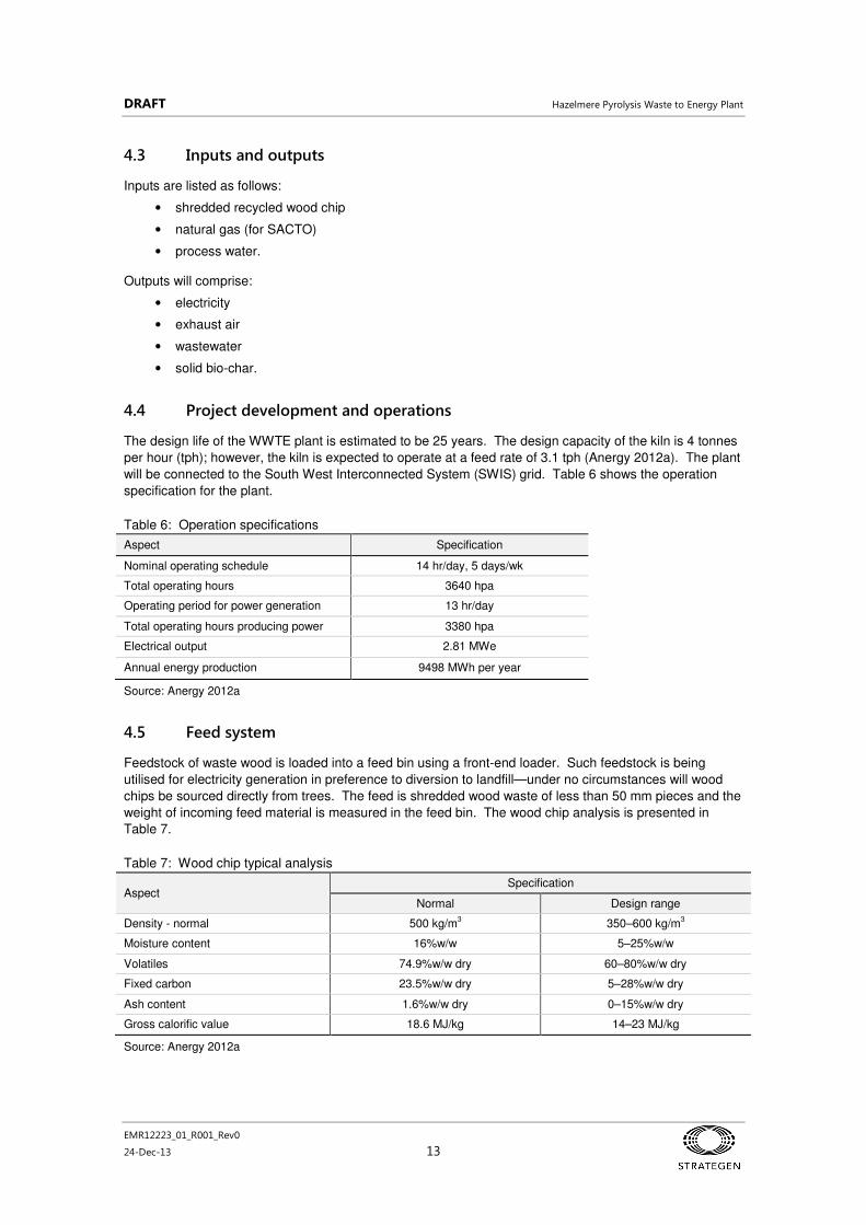
4.4 Project development and operations
The design life of the WWTE plant is estimated to be 25 years. The design capacity of the kiln is 4 tonnes
per hour (tph); however, the kiln is expected to operate at a feed rate of 3.1 tph (Anergy 2012a). The plant
will be connected to the South West Interconnected System (SWIS) grid. Table 6 shows the operation
specification for the plant.
Table 6: Operation specifications
Aspect Specification
Nominal operating schedule 14 hr/day, 5 days/wk
Total operating hours 3640 hpa
Operating period for power generation 13 hr/day
Total operating hours producing power 3380 hpa
Electrical output 2.81 MWe
Annual energy production 9498 MWh per year
Source: Anergy 2012a
4.5 Feed system
Feedstock of waste wood is loaded into a feed bin using a front-end loader. Such feedstock is being
utilised for electricity generation in preference to diversion to landfill—under no circumstances will wood
chips be sourced directly from trees. The feed is shredded wood waste of less than 50 mm pieces and the
weight of incoming feed material is measured in the feed bin. The wood chip analysis is presented in
Table 7.
Table 7: Wood chip typical analysis
Aspect Specification
Normal Design range
Density - normal 500 kg/m3 350–600 kg/m
3
Moisture content 16%w/w 5–25%w/w
Volatiles 74.9%w/w dry 60–80%w/w dry
Fixed carbon 23.5%w/w dry 5–28%w/w dry
Ash content 1.6%w/w dry 0–15%w/w dry
Gross calorific value 18.6 MJ/kg 14–23 MJ/kg
Source: Anergy 2012a

DRAFT Hazelmere Pyrolysis Waste to Energy Plant
EMR12223_01_R001_Rev0
24-Dec-13 14
4.6 Pyrolysis unit
Material is drawn out of the kiln bin at a nominated rate by a conveyor. Excess moisture is removed from
feedstock through exposure to warm flue gases from the kiln combustion chamber and a twin screw is
utilised to feed material into the kiln (Anergy 2012a).
Pyrolysis occurs inside the heat tube of the rotary indirect fired kiln, where moisture and volatile fractions
undergo pyrolysis in the absence of oxygen at approximately 800˚C. Solids (char) separate out at the
base of the discharge chamber and syngas is captured and discharged from the chamber for cleaning.
Table 8: Kiln specifications
Aspect Specification
Normal Design range
Kiln capacity 3.1 t/hr 1.5–4.0 t/hr
Operating tube temperature 750˚C 700–850˚C
Residence time 25 min 20–40 min
Maximum tube temperature 900 ˚C 900 ˚C
Ambient combustion are temperature 20˚C 5–35˚C
Specific energy input 1.25 kW/kg 0.80–1.6 kW/kg
Source: Anergy 2012a
4.7 Gas cleanup
Prior to cleaning, the syngas contains a mixture of compounds summarised in Table 9. Cleaning is
conducted using a char bed. Tar compounds, dust, remaining tars and excess moisture are removed
using a steam reforming catalyst (exact catalyst yet to be determined), with oxygen used to maintain the
necessary heat for the reaction. The cleaned gas is then transported back to the kiln for heating fuel and
used in the gas engines for energy production.
Table 9: Kiln products
Gas Cleaning process Purpose
hydrogen (H2) Resultant syngas component
carbon monoxide (CO) Resultant syngas component
carbon dioxide (CO2) Resultant syngas component
steam Resultant syngas component
light paraffin (methane, ethane, propane)
Resultant syngas component
light olefins (acetylene, ethylene) Resultant syngas component
light aromatics (benzene, toluene) Resultant syngas component
ammonia Condensed at low temperatures
acid gases (hydrogen sulphide, hydrogen chloride)
Condensed at low temperatures
nitrogen and inert gases
light tars - polycyclic aromatic hydrocarbons (PAH)
Reformer and condensed at low temperatures
Recover as much as possible by conversion into H and CO
heavy tars - polycyclic aromatic hydrocarbons (PAH)
Reformer and condensed at low temperatures
Recover as much as possible by conversion into H and CO
Char Removed as a solid Not applicable to energy generation
Dust Condensed at low temperatures Not applicable to energy generation
Source: Anergy 2012a

DRAFT Hazelmere Pyrolysis Waste to Energy Plant
EMR12223_01_R001_Rev0
24-Dec-13 15
4.8 Bio-char output
Bio-char is a by-product of the pyrolysis process. The char exits the kiln at high temperatures and is
placed on a cooling conveyor which both transports the char and cools it to less than 80°C. Water sprays
are also used to ensure the temperature of the product is lowered (which reduces the potential for char
dust). The char is then stored for eventual transport offsite. The use for the bio-char is yet to be
determined; however, bio-char can be used in applications such as agricultural applications in soil and in
brick manufacturing as a fuel substitute. If no market is available for the bio-char, it would report to landfill.
4.9 Wastewater treatment
Once enough wastewater is collected in the holding tank, a batch treatment operation is started. During
this operation, liquor is pumped through an activated carbon column and then discharge into a tank for re-
use in the process. Water is tested by manual sampling to ensure appropriate quality. If the activated
carbon has reached peak loading, the column will be replaced and sent for reprocessing.
4.10 Thermal oxidiser
A SACTO is used to balance the load of syngas between engines and kilns by combusting all excess
gases. The SACTO uses a natural gas pilot burner to establish temperature for a given gas residence
time and is maintained at 850˚C with excess oxygen. It will also have a small diesel generator for
contingency backup. Staged air flow is used to encourage a swirl within the unit to maximise mixing and
temperature to achieve complete combustion. Exhaust from the pyrolysis kiln and the SACTO is delivered
to the exhaust stack, where dilution air is added to achieve lower exhaust temperatures. SACTO
specifications are outlined in Table 10.
Table 10: SACTO specifications
Aspect Specification
Normal Design range
SACTO residence time 1.3 s
SACTO temperature 850˚C 800–1250˚C
Exhaust stack 400˚C 250–425˚C
Source: Anergy 2012a
4.11 Gas engines
Syngas is combusted in eight 500 kW gas engines generator sets, each within an audio enclosure. Gas
engine generating sets are made up of gas engines, alternators and ancillary equipment (safety valves,
pipe-work, coolant system, control panel, ignition system, air-fuel ratio system).
The eight engine sets are controlled using a multiple-generator management system which controls the
start-up and load of each of the eight units. Roof-mounted radiators with electrically-driven fans are used
to cool engines. Specifications for the engines are outlined in Table 11.
Table 11: Engine specifications
Aspect Specification
Normal Design range
Engine syngas de-rate 75% 70–80%
Gas to generation efficiency 34%
Syngas demand 1880 kg/hr 1388–2042 kg/hr
Alternator voltage 415 V
Gas flow requirement per module 235 Nm3/hr
Source: Anergy 2012a

DRAFT Hazelmere Pyrolysis Waste to Energy Plant
EMR12223_01_R001_Rev0
24-Dec-13 16
4.12 Utilities and plant services
The plant will require:
• water
• oxygen
• nitrogen
• natural gas (see specifications in Table 12) and diesel fuel (for contingency backup)
• high voltage power lines.
Table 12: Service specifications for natural gas
Aspect Specification
Natural gas pressure 140 kPag
Natural gas gross calorific value 39 MJ/Nm3
Maximum natural gas rate 4000 MJ/h
Source: Anergy 2012a
The plant requires general utilities including:
• cooling and process water circuit
• plant air and instrument air compressors and drying service
• oxygen plant for 90% oxygen for steam reforming
• nitrogen for plant purging.
Plant services equipment required include:
• fire water tank including diesel engine pump and electrical pump
• control room, low-voltage switch room and high-voltage switch room
• maintenance workshop
• office equipment and support facilities
• effluent consolidation and discharge
• distribution transformer.
4.13 Personnel
Operation of the plant will require skilled staff that has been provided with appropriate training. Plant
maintenance will require regular staff with additional external advice on occasion. The Human Machine
Interface (HMI) to be located in the control room allows for two staff.
4.14 Procedural controls
Procedural controls will include:
• permits to work
• hot work permits
• isolation
• control system override and maintenance
• confined space entry.
4.15 Personal protective equipment control
Compulsory personal protective equipment required on site will comprise hard hats, safety glasses
(darkened and clear), gloves (handling and hot surfaces) and hearing protection (in limited areas).

DRAFT Hazelmere Pyrolysis Waste to Energy Plant
EMR12223_01_R001_Rev0
24-Dec-13 17
5. Environmental management
The environmental factors are considered to be:
• noise emissions
• dust emissions
• air emissions
• odour
• wastewater disposal
• groundwater management
• fire risk
• traffic management.
The listed factors are discussed in this section.
5.1 Noise emissions
Environmental noise can cause disturbance to nearby residents, industrial and commercial operators if
noise is above levels designated in state legislation and regulations. Operational noise is considered an
environmental factor in assessing possible impacts of the WWTE plant.
Noise modelling has been conducted by Lloyd George Acoustics (2013) to assess the proposed noise
levels of the operational WWTE plant. The full report is contained in Appendix 2. Modelling has assumed
the plant runs from 0800–2200 hrs, Monday to Friday.
The design goal for the WWTE is to achieve noise levels at each premises at 5 dB below the assigned
level to compensate for other potential noise sources in the vicinity and provide an allowance for tonality, if
the noise is tonal.
5.1.1 Sensitive receptors
Nine sensitive receptors were identified surrounding the proposed location of the WWTE plant (Figure 3).
Each of these sensitive receptors has an individual influencing factor incorporated into their assigned level
to take into account the proximity of background noise from industrial or commercial sites or road traffic.
The assigned level comprises the criteria of ‘acceptable noise levels’ received by the premises.
Industrial land is located on the northern and eastern boundaries.
5.1.2 Results
Modelling results for daytime hours, summarised in Table 13, shows that noise levels are predicted to
comply with assigned levels at all sensitive premises and to comply with the design goal of 5 dB under the
assigned noise level.
Table 13: Results of noise modelling (daytime; Mon-Sat 0700-1900)
ID Location
Baseline assigned
level
Influencing factor
Assigned noise level
Predicted noise level
Difference between predicted and
assigned noise level
LA10 (dB) (dB) LA10 (dB) LA10 (dB) (dB)
1 Lakes Road 45 6 51 42 9
2 Lakes Road 45 9 54 45 9
3 Lakes Road 45 5 50 41 9
4 Lakes Road 45 3 48 37 11

DRAFT Hazelmere Pyrolysis Waste to Energy Plant
EMR12223_01_R001_Rev0
24-Dec-13 18
ID Location Baseline assigned
level
Influencing factor
Assigned noise level
Predicted noise level
Difference between predicted and
assigned noise level
5 Lakes Road 45 1 46 34 12
6 Lakes Road 45 1 46 33 13
7 Hazelmere Circus 45 1 46 32 14
8 Bushmead Road 45 7 52 35 17
9 Stirling Crescent 45 4 49 37 12
10 BGC – site within 15 m of building
65 0 65 53 12
11 BGC site – near site boundary
65 0 65 57 8
Source: Lloyd George Acoustics 2013
Modelling results for evening hours, summarised in Table 14, shows noise levels are predicted to comply
with assigned levels at all sensitive premises; however, noise levels are within the design goal of 5 dB of
assigned levels at three premises. This will only occur under worst-case meteorological conditions in the
evening.
Table 14: Results of noise modelling (evening; Mon-Sat 1900-2200)
ID Location
Baseline assigned
level
Influencing factor
Assigned noise level
Predicted noise level
Difference between predicted and
assigned noise level
LA10 (dB) (dB) LA10 (dB) LA10 (dB) (dB)
1 Lakes Road 40 6 46 42 4
2 Lakes Road 40 9 49 45 4
3 Lakes Road 40 5 45 41 4
4 Lakes Road 40 3 43 37 6
5 Lakes Road 40 1 41 34 7
6 Lakes Road 40 1 41 33 8
7 Hazelmere Circus 40 1 41 32 9
8 Bushmead Road 40 7 47 35 12
9 Stirling Crescent 40 4 44 37 7
10 BGC – site within 15m of building
65 0 65 53 12
11 BGC site – near site boundary
65 0 65 57 8
Source: Lloyd George Acoustics 2013
In order to achieve the design target of noise levels below 5 dB of the assigned noise level, acoustic
silencers or enclosures will be used on both combustion fans as a form of noise control, with a target of
3 dB reduction in source sound levels.
5.1.3 Noise monitoring
With the inclusion of recommended acoustic silencers or enclosures on combustion fans, no noise
monitoring is considered to be required as predicted noise levels at receiver locations are predicted to be
below assigned level criteria.

DRAFT Hazelmere Pyrolysis Waste to Energy Plant
EMR12223_01_R001_Rev0
24-Dec-13 19
5.2 Dust emissions
5.2.1 Potential dust sources
Dust generation is identified as a potential environmental impact resulting from earthworks carried out to
prepare the site. Dust may arise from ground disturbance (vehicle traffic and excavation) as well as from
errant sources (windblown dust from stockpiled soil).
Once the site is operational, airborne dust may occur as a result of the fuel type (wood chip) as well as the
by-product (bio-char).
5.2.2 Construction emissions
Dust management will be carried out throughout clearing and construction to negate or reduce the
generation of visible dust across site boundaries. Dust suppression methods to be employed may include:
• restriction of traffic to designated haul roads
• use of soil-binders on haul roads
• use of a water cart and/or sprinklers
• application of hydromulch
• covering stockpiles
• restricting operations to low wind conditions (<20 km/h)
• use of site boundary fencing reinforced with shadecloth along western and eastern boundaries to
intercept dust during peak wind conditions
• strict enforcement of speed limits onsite (20 km/h).
5.2.3 Operational emissions
Dust emissions are present currently from the timber grinding operation at the Hazelmere Recycling
Centre; therefore, it is considered that the impact from this proposed plant would be no greater than that is
currently experienced at the site. Dust may also be generated as the bio-char exits the pyrolysis kiln;
however, during transport (by conveyor) and prior to the bio-char being packaged in bulka-bags, the bio-
char is quenched with water; therefore, the generation of dust is limited. Particulates from the stack are
not in excess of NEPM limits (see Section 5.3.6); therefore, particulates are not expected to be an issue
from the stack or the generator sets.
5.2.4 Monitoring
While dust may be present during both construction and operations, it is not envisaged to travel beyond
site boundaries. Onsite management during construction will aim to ameliorate airborne dust, similarly
onsite management measures will ensure airborne dust does not pose a risk to human or environmental
health. The monitoring of levels of airborne particulate matter (whether nuisance dust, respirable or
inhalable dust) is not foreseen to contribute effectively to better dust management at the site. As such, no
dust monitoring is proposed at this stage.

DRAFT Hazelmere Pyrolysis Waste to Energy Plant
EMR12223_01_R001_Rev0
24-Dec-13 20
5.3 Air emissions
An assessment of the impacts of air emissions from point sources within the WWTE plant has been carried
out using dispersion modelling as per guidance notes provided by DER (2006). The assessment has
included direct impacts of emissions as well as cumulative impacts, whereby the background air quality is
considered in conjunction with the additional emissions from the WTE facility. Key elements of the
assessment include:
• construction of an emissions inventory for the two point sources (main stack and gas engine
exhaust stacks)
• development of emissions scenarios that reflect normal plant operations and plant outages
• comparison of emissions concentrations with emission limits from the EU WID (EU 2000)
• collation of background air quality data for the cumulative impact
• assembly of air quality standards (assessment criteria) relevant to impacts from wte projects
• air dispersion modelling to generate predicted ground level concentrations (glcs) of air emissions
• comparison of predicted GLCs with air quality standards for direct and cumulative impact
assessments
• plume rise assessment as per requirements from the Civil Aviation Safety Authority (CASA).
Further details of these activities are provided in the following sections.
5.3.1 Emissions inventory
The air emissions assessment has focussed on parameters detailed in the EPA report on WTE
environmental and health performance (EPA 2013), with these parameters and emission concentration
limits derived from the EU WID. Emissions testing data of sufficient quality and quantity from an operating
facility were not available for all of these parameters for the emissions assessment. As a consequence, a
comprehensive emissions inventory has been developed from consideration of measured compositional
data for the wood feed materials and key process design parameters that influence the formation and fate
of air emissions within the process.
The maximum emission rates calculated in the emissions inventory for each of the WID parameters have
been used for the dispersion modelling. These reflect a conservative position for the combination of all the
potential process operating conditions as envisaged at this stage of the project development. Key process
variables will be optimised in the operating facility, with some of those directly affecting air emissions
outcomes. In particular, three types of catalyst have been proposed for the raw syngas reformer (dolomite,
char and nickel catalyst) which provide different chemistries for some emission parameters or their
precursors. In addition, the scrubber water operating pH may range from acidic to alkaline depending on
the exact composition of the reformed syngas from the three catalyst options. As a consequence, the
impact of the different reformation catalysts and scrubbing at both acidic (pH 4) and alkaline (pH 9)
conditions has been considered in the emissions inventory.
The exact form of heavy metals that report to the dirty syngas from the pyrolysis kiln is not known with
certainty so three metals scenarios have been considered where the physical properties (melting and
boiling points) of metals as the free metal, metal sulfides and metal oxides have been used to predict their
partitioning in the reformation and scrubbing processes. Full details of these considerations and the
emissions inventory are reported in Strategen 2013a.
The emissions data used for the dispersion modelling is presented in Table 15.1
Details of the emission
scenarios for normal and reduced rate operations and emergency bypass conditions (for unplanned plant
outages) are presented in Section 5.3.2.
1
The values have been displayed in the MS Excel scientific format for direct integration into the dispersion model.

DRAFT Hazelmere Pyrolysis Waste to Energy Plant
EMR12223_01_R001_Rev0
24-Dec-13 21
Table 15: Emissions data for dispersion modelling
Emissions Units
Main stack - maximum values Gas engines - maximum values
Normal emissions
Reduced rate emissions
Bypass emissions
Normal emissions
Reduced rate emissions
Bypass emissions
NOx g/s 6.93E-02 1.74E-01 9.05E-01 1.93E+00 9.63E-01 0.00E+00
SO2 g/s 2.90E-02 7.43E-02 1.51E-01 9.47E-02 4.73E-02 0.00E+00
CO g/s 7.60E-02 1.95E-01 4.15E-01 2.97E+00 1.49E+00 0.00E+00
Total VOC g/s 8.19E-03 2.08E-02 4.00E-02 6.19E-02 3.09E-02 0.00E+00
HCl g/s 1.51E-04 3.86E-04 2.10E-02 4.92E-04 2.46E-04 0.00E+00
HF g/s 5.08E-05 1.30E-04 3.94E-04 1.66E-04 8.31E-05 0.00E+00
Hg g/s 8.05E-08 2.07E-07 5.61E-06 2.63E-07 1.32E-07 0.00E+00
Cd g/s 4.20E-08 1.08E-07 2.20E-04 1.37E-07 6.87E-08 0.00E+00
Tl g/s 9.05E-08 2.32E-07 1.89E-04 2.96E-07 1.48E-07 0.00E+00
Sb g/s 5.37E-09 1.38E-08 3.74E-06 1.75E-08 8.77E-09 0.00E+00
As g/s 4.89E-06 1.25E-05 3.41E-03 1.60E-05 7.99E-06 0.00E+00
Cr g/s 1.16E-07 2.97E-07 6.06E-04 3.79E-07 1.89E-07 0.00E+00
Co g/s 7.16E-11 1.84E-10 3.74E-07 2.34E-10 1.17E-10 0.00E+00
Cu g/s 1.45E-07 3.71E-07 7.57E-04 4.73E-07 2.37E-07 0.00E+00
Pb g/s 7.24E-08 1.86E-07 3.79E-04 2.37E-07 1.18E-07 0.00E+00
Mn g/s 1.43E-13 3.67E-13 7.48E-10 4.68E-13 2.34E-13 0.00E+00
Ni g/s 9.05E-08 2.32E-07 1.89E-04 2.96E-07 1.48E-07 0.00E+00
V g/s 3.58E-10 9.18E-10 3.74E-07 1.17E-09 5.85E-10 0.00E+00
Particulates g/s 9.40E-03 3.61E-03 3.32E-01 7.22E-03 3.61E-03 0.00E+00
Dioxins g TEQ/s 6.74E-12 1.74E-11 2.88E-11 2.20E-11 1.10E-11 0.00E+00
Notes: NOx = oxides of nitrogen, includes nitric oxide (NO) and nitrogen dioxide (NO2). Reported as NO2 equivalents
Total VOC = volatile organics as carbon, also known as total organic carbon (TOC)
Particulates = total suspended particulates (TSP), PM10 and PM2.5 (assume PM10 = TSP and PM2.5 = TSP for
air quality impact assessment)
Dioxins = sum of polychlorinated dibenzo-p-dioxins and polychlorinated dibenzofuran congeners factored by
their respective toxic equivalency factors
5.3.2 Emissions scenarios
Five operating scenarios have been considered for the air emissions impact assessment, which give rise
to three emissions scenarios for the modelling as identified in Table 15. An overview of these operating
scenarios is summarised in Table 16.
Table 16: Operating scenarios for air emissions assessment
Operating scenario
Emission scenario
Description Comment
1. Continuous normal operations
Normal emissions
Plant operating continuously at 3100 kg/h wood feed rate
Operations 24 hours per day, 7 days per week
2. High power demand normal operation
Normal emissions
Plant operating at 3100 kg/h wood feed rate for weekdays only
Operations 14 hours per day, 5 days per week from 8 am to 10 pm, with start-up from 7 am to 8 am, feed terminated at 10 pm and standby from 11 pm to 7 am next day

DRAFT Hazelmere Pyrolysis Waste to Energy Plant
EMR12223_01_R001_Rev0
24-Dec-13 22
Operating scenario
Emission scenario
Description Comment
3. Reduced rate operations
Reduced rate emissions
Four of the gas engines on-line and four off-line. Excess syngas incinerated in SACTO. Feed rate adjusted to match engine availability
Scenario assumes continuous emissions for up to 2 hours as a conservative position for emissions impact assessment. Actual duration of this scenario will be < 30 minutes, as the feed rate will be reduced. Scenario terminates when either all engines return to service or process is shutdown to standby mode or full shutdown.
4. Syngas clean-up system outage
Bypass emissions
Raw syngas diverted directly to SACTO for incineration, wood feed shut-down
Scenario covers outage of reformer or syngas scrubber and assumes continuous emissions for up to 1 hour after bypass activated. Actual duration will be < 30 minutes as bypass occurs immediately a failure of the syngas clean-up system is detected and wood feed is terminated to stop production of raw syngas
5. Plant power outage
Bypass emissions
Raw syngas diverted directly to SACTO for incineration, other systems off-line
Scenario covers loss of power supply to the facility. Backup power supply via diesel generator will maintain operation of SACTO and key control systems to ensure syngas in the clean and raw syngas headers is safely diverted to the SACTO for incineration. Actual duration will be <30 minutes as production of raw syngas decays from shut-down of feed and cooling of pyrolysis chamber.
EMRC expects that the initial operation of the facility would be under a peak power demand operating
scenario, which reflects the expected power take-off arrangements that would be negotiated where power
is supplied to customer(s) for peak demand periods only, nominally 14 hours per day for 5 days per week.
The continuous normal operating scenario (continuous operation 24 hours per day, 7 days per week) may
eventuate if demand is identified for power from this facility at all times. The predicted GLCs for the
continuous normal operation were assumed to prevail for the peak power demand (normal) operating
scenario to provide a conservative approach for assessment of impacts in the initial stages of operation.
Emissions from start-up and controlled shut-down operations are covered under the reduced rate scenario,
which provides a worst case estimate of the emissions under those conditions. The actual times required
to reach steady state operations from start-up and shutdown condition are expected to be less than those
assumed in these scenarios, providing a conservative basis for the emissions assessments.
5.3.3 Main stack emissions concentrations and WID limits
The EPA guidance document (EPA 2013) requires emissions from a WTE facility to be compared with the
WID concentration limits. This is appropriate for operation under bypass conditions, when raw syngas is
fed directly to the SACTO for combustion. The raw syngas is not a fuel that can be utilised for production
of electricity due to the presence of tars, particulates, metals and other contaminants that would otherwise
be removed under normal operating conditions in the reformer and scrubber to produce clean syngas.
A comparison of maximum predicted emission concentrations from the main stack with WID limits for
normal operation is shown in Table 17. The short duration expected for operation under this scenario
(<30 minutes) suggests that the 30-minute average limits are more appropriate for comparison with the
predicted stack emissions than the daily average limits.

DRAFT Hazelmere Pyrolysis Waste to Energy Plant
EMR12223_01_R001_Rev0
24-Dec-13 23
Table 17: Comparison of emission concentrations and WID limits – bypass operation
Emission parameter
Maximum concentration (mg/Nm
3 @
11% O2)
EU WID limit (mg/Nm
3 @
11% O2) Averaging period Limit type
Concentration as % of WID
limit
NOX 64
200 daily average maximum 32%
400 30 min average maximum 16%
200 30 min average 97% of observations over 12 months 32%
SO2 10.8
50 daily average maximum 22%
200 30 min average maximum 5.4%
50 30 min average 97% of observations over 12 months 22%
CO 30
50 daily average maximum 59%
100 30 min average maximum 30%
150 30 min average 95% of observations over 12 months 20%
TOC (VOCs) 2.85
10 daily average maximum 28%
20 30 min average maximum 14%
10 30 min average 97% of observations over 12 months 28%
HCl 1.5
10 daily average maximum 15%
60 30 min average maximum 2.5%
10 30 min average 97% of observations over 12 months 15%
HF 0.028
1 daily average maximum 2.8%
4 30 min average maximum 0.70%
2 30 min average 97% of observations over 12 months 1.4%
Hg 0.00025
0.05 30 min to 8 h average maximum 0.49%
0.1 30 min to 8 h average 97% of observations over 12 months
0.25%
Cd + Tl 0.018
0.05 30 min to 8 h average maximum 36%
0.1 30 min to 8 h average 97% of observations over 12 months
18%
Other metals (As, Sb, Co, Cr, Cu, Pb, Mn, Ni, V)
0.23
0.5 30 min to 8 h average maximum 47%
1 30 min to 8 h average 97% of observations over 12 months
24%
Particulates 3.2
10 daily average daily average 32%
30 30 min average maximum 11%
10 30 min average 97% of observations over 12 months 32%
Dioxins 0.00000057 ng TEQ/Nm
3
0.1 ng TEQ/Nm
3
6 to 8 h average maximum 0.00057%
No exceedances of the WID limits are predicted for the emissions under bypass conditions.
A comparison of the stack emissions from normal operating conditions with the WID is considered by the
proponent to be outside the scope of the EPA guidance document. Under those conditions the emissions
result from combustion of clean syngas in the kiln burners and a small amount from combustion of natural
gas in the SACTO under idle conditions. Similarly, a comparison of stack emissions from reduced rate
operating conditions is also considered outside the scope of the EPA guidance document as clean syngas
will also be combusted in the SACTO until the clean syngas production rate is reduced to satisfy the
reduced demand from the engines that remain on-line.

DRAFT Hazelmere Pyrolysis Waste to Energy Plant
EMR12223_01_R001_Rev0
24-Dec-13 24
Emissions from combustion of clean syngas will be predominately CO2 and water, with smaller amounts of
NOx and CO, as the vast majority of contaminants have been removed from the raw syngas in the
reformation and scrubbing processes that generates the clean syngas. The clean syngas is a fuel and not
a waste.
5.3.4 Gas engine exhaust emissions concentrations and WID limits
Recommendation 8 of the WTE guidance document from WA EPA specifies that:
“…waste to energy plants should be required to use best practice technologies and processes. Best
practice technologies should, as a minimum and under both steady state and non-steady state operating
conditions, meet the equivalent of the emissions standards set in the European Union’s Waste Incineration
Directive (2000/76/EC).”
The use of spark ignition engines for generation of electricity from combustion of clean syngas at the scale
of the proposed facility is best practice technology in terms of energy utilisation, availability, reliability,
emissions performance and cost effectiveness. However, there are no emissions standards in the WID
applicable to combustion of clean syngas from WTE facilities using gas engines. Clean syngas from the
proposed Hazelmere WTE facility is a fuel that will be comprised of predominately carbon monoxide,
hydrogen, carbon dioxide and water vapour. Key precursors for air emissions such as acid gases (HCl,
HF and SO2), heavy metals and dioxins will have been removed from the clean syngas in the reformer and
scrubber.
The WID is specifically designed to manage emissions from incineration of waste, whereas syngas is not a
waste material but a fuel with similar combustion emission properties to natural gas. As a consequence, a
comparison of emission concentrations from the gas engines with the WID limits is considered by the
proponent as not applicable to this project.
Support for this position is provided in the judgement from the EU Court in the matter of Lahti Energia Oy
and the combustion of non-purified syngas in a power plant boiler (EU 2010). The judgement states that
“A power plant which uses as an additional fuel, in substitution for fossil fuels used for the most
part in its production activities, gas obtained in a gas plant following thermal treatment of waste is
to be regarded, jointly with that gas plant, as a ‘co-incineration plant’ within the meaning of Article
3(5) of Directive 2000/76/EC of the European Parliament and of the Council of 4 December 2000
on the incineration of waste when the gas in question has not been purified within the gas plant.”
The implication of that judgement is that a facility which does purify the syngas for combustion in a power
plant is not considered a co-incineration plant and as a consequence the WID (and associated emission
limits) is not applicable to the combustion of clean syngas to generate electricity.
An assessment of predicted environmental impacts of emissions from the gas engines using dispersion
modelling is described in Section 5.3.6.
5.3.5 Background air quality data and assessment criteria
EMRC has previously conducted an air emission assessment as part of environmental approvals for a
proposed Resource Recovery Facility (WTE [gasification] or anaerobic digestion technology) at their Red
Hill operations on Toodyay Road which includes ambient air data from monitoring carried out on the Red
Hill site and in the nearby communities (EMRC 2012). In that work, those data were compared with other
public domain data from the Midland area and the DER Rolling Green AQMS and found to be of similar
magnitude in concentrations. The Red Hill data are considered appropriate for use in this assessment to
determine the cumulative impacts of air emissions from the WWTE plant.

DRAFT Hazelmere Pyrolysis Waste to Energy Plant
EMR12223_01_R001_Rev0
24-Dec-13 25
The air quality criteria and standards used in the Red Hill RRF assessment are considered appropriate for
the Hazelmere project. A thorough review of air quality criteria was conducted for the Red Hill project that
included consultation with the Department of Health (DoH) toxicology section. The criteria selected
reflected the view of that agency and were considered at that time as best practice for assessment of air
emission impacts WTE projects in WA. No change in that status has occurred since the submission of
approvals documentation for the Red Hill project.
Included in the criteria is a concentration limit for nitrogen dioxide (NO2), which is the oxide of nitrogen with
the greatest health impact significance. The oxides of nitrogen (NOX) emissions from the WTE have been
estimated as both nitric oxide (NO) and NO2, since these are the dominant forms present in air emissions
from combustion sources, with NO typically constituting 90% and NO2 the remainder of the NOX
emissions.2
A conservative assumption is made for the impact assessment that the NO emissions
immediately contribute to ground level impacts as NO2, even though considerably longer time is required
for conversion of NO to NO2 in the atmosphere.
The assessment criteria include a concentration limit for hexavalent Chromium (CrVI
), which is the most
toxic form of Chromium that potentially can be emitted from thermal processes. A conservative estimate of
the CrVI
concentrations was made using the approach adopted by EMRC for the Red Hill assessment, in
that CrVI
is 10% of the total Cr (EMRC 2012).
Air quality criteria are available for particulate matter (PM) as total suspended particulates (TSP) and the
PM10 and PM2.5 size fractions. The emissions inventory includes predictions of TSP concentrations in the
emissions from the WTE facility which can be compared with the Kwinana Environmental Protection Policy
1992 (TSP Area C) standard (90 µg/m3). Reliable estimates of fine particle emission rates from the facility
cannot be made so a conservative assumption has been made that the TSP is 100% PM10 for the air
quality assessment of that size fraction and similarly, TSP is 100% PM2.5. The concentrations have been
compared with the Ambient Air Quality NEPMs (50 and 25 µg/m3 for PM10 and PM2.5, respectively).
VOC emissions have been estimated as TOC; however, ambient air quality standards are not available for
this parameter.
Details of the assessment criteria and background concentrations used for the Hazelmere WTE
assessment are shown in Table 18.
2
Small amounts of nitrous oxide (N2O) can also be formed

DRAFT Hazelmere Pyrolysis Waste to Energy Plant
EMR12223_01_R001_Rev0
24-Dec-13 26
Table 18: Air quality assessment criteria and background concentrations
Pollutant Assessment criteria
averaging Period Assessment criteria
(µg/m3)
WA relevant guideline Background concentration for impact assessment (µg/m
3)
% of assessment criteria
NO2 1 hour 246 AAQ NEPM (NEPC 2003) 30 12%
Annual 61.6 AAQ NEPM (NEPC 2003) 2 4%
SO2 10 min 500 WHO guidelines for air quality (WHO 2000), WHO AQ guidelines global update (WHO 2005)
18 4%
1 hour 571.8 AAQ NEPM (NEPC 2003) 18 3%
24 h 228.7 AAQ NEPM (NEPC 2003) 19 8%
Annual 57.2 AAQ NEPM (NEPC 2003) 1 3%
CO 15 min 100 000 WHO guidelines for air quality (WHO 2000) 480 0.5%
30 min 60 000 WHO guidelines for air quality (WHO 2000) 460 1%
1 hour 30 000 WHO guidelines for air quality (WHO 2000) 460 2%
8 hour 11 249 AAQ NEPM (NEPC 2003) 380 3%
VOCs (as TOC) N/A No criterion No criterion N/A N/A
HCl 1 hour 100 WA Department of Health - Acid Gases 2007 (DOH 2007) 30 30%
HF 1 hour 100 WA Department of Health - Acid Gases 2007 (DOH 2007) 5 5%
As 1 hour 0.09 Approved methods for the assessment of air pollutants in NSW (DEC NSW 2005)
0.01 14%
Annual 0.003 Air guideline values for selected substances (Toxikos 2010) 0.001 33%
Cd 1 hour 0.018 Approved methods for the assessment of air pollutants in NSW (DEC NSW 2005)
0.006 35%
Annual 0.005 WHO guidelines for air quality (WHO 2000) 0.0005 10%
Co 24 hour 0.1 Ontario’s Ambient Air Quality Criteria (Ontario MOE 2008) 0.01 10%
Cr (VI) Annual 0.0002 Air guideline values for selected substances (Toxikos 2010) 0.00007 35%
Cr(III) 1 hour 10 Air guideline values for selected substances (Toxikos 2010) 0.02 0.2%
Cu 24 hour 1 Air guideline values for selected substances (Toxikos 2010) 0.008 0.8%
Hg 1 hour 1.8 Approved methods for the assessment of air pollutants in NSW (DEC NSW 2005)
0.001 0.1%
Annual 1 WHO guidelines for air quality (WHO 2000) 0.0001 0.01%
Mn 1 hour 18 Approved methods for the assessment of air pollutants in NSW (DEC NSW 2005)
0.04 0.2%
Annual 0.15 WHO guidelines for air quality (WHO 2000), Air guideline values for selected substances (Toxikos 2010)
0.003 2%

DRAFT Hazelmere Pyrolysis Waste to Energy Plant
EMR12223_01_R001_Rev0
24-Dec-13 27
Pollutant Assessment criteria
averaging Period Assessment criteria
(µg/m3)
WA relevant guideline Background concentration for impact assessment (µg/m
3)
% of assessment criteria
Ni 1 hour 0.18 Approved methods for the assessment of air pollutants in NSW (DEC NSW 2005)
0.01 7%
Annual 0.003 DOH Esperance Ni annual guideline (DOH 2011) 0.001 33%
Pb Annual 0.5 AAQ NEPM (NEPC 2003), WHO guidelines for air quality (WHO 2000) 0.02 4%
Sb 1 hour 9 Approved methods for the assessment of air pollutants in NSW (DEC NSW 2005)
0.01 0.1%
Tl 1 hour 1 TCEQ Effect Screening Levels (TCEQ 2011) 0.01 1%
Annual 0.1 TCEQ Effect Screening Levels (TCEQ 2011) 0.001 1%
V 24 hour 1 WHO guidelines for air quality (WHO 2000) 0.008 0.8%
PM as TSP 24 hour 90 Kwinana Environmental Protection Policy 1992 (TSP Area C) (WA Government 1992)
32 36%
PM10 24 hour 50 AAQ NEPM (NEPC 2003), WHO AQ guidelines global update (WHO 2005)
20 40%
PM2.5 24 hour 25 AAQ NEPM (NEPC 2003), WHO AQ guidelines global update (WHO 2005)
6 26%
Annual 8 AAQ NEPM (NEPC 2003) 1 16%
Dioxins
(TEQ)3
1 hour 0.000001 Air guideline values for selected substances (Toxikos 2010) 0.00000048 48%
3
TEQ calculated from WHO 2005 TEFs

DRAFT Hazelmere Pyrolysis Waste to Energy Plant
EMR12223_01_R001_Rev0
24-Dec-13 28
5.3.6 Dispersion modelling
Methodology
Dispersion modelling of emissions from the two point sources (main stack and gas engine exhaust stacks)
was carried out by Environ Australia Pty Ltd (Environ 2013) using the AERMOD atmospheric dispersion
model. Meteorological data were obtained from the Perth Airport station and upper air data generated
using TAPM.4
Full details of the modelling configuration are provided in the report from Environ (2013)
located in Appendix 3.
Three residences to the west of the EMRC Hazelmere site were identified as sensitive receptors for the
emissions impact assessment (Figure 3), with industrial premises surrounding the remainder of the EMRC
site.
Tabulated results are reported in the following sections for predicted ground level concentrations (GLCs) at
receptor R2, which is the nearest sensitive receptor to the proposed WWTE plant and is predicted to
experience the highest impact from the facility. The receptor is located on Lot 99(2), which EMRC is
negotiating acquisition of for inclusion of a community reuse, recycling and drop-off centre for the RRP
(approval for which is not being sought in this application). Therefore, it is likely that this receptor will be
removed in the future.
Results from dispersion modelling – direct impact assessment
The results from the dispersion modelling of Scenarios 1 and 2 (normal operations) are summarised in
Table 19 for the R2. This includes a comparison with the respective assessment criteria to provide a direct
impact assessment for the emissions of interest.
No exceedances of the air quality criteria were observed for these maximum predicted GLCs. The most
significant emission was NO2 (NOX), with a maximum predicted 1-hour average GLC of 26% of the air
quality criterion. A contour plot showing the distribution of maximum predicted 1-hour average NO2 GLCs
is shown in Figure 4. Predicted GLCs for all other emissions parameters were well below their respective
air quality criteria.
The results from the dispersion modelling of Scenario 3 (reduced rate operations) are summarised in
Table 20. This includes a comparison with the respective assessment criteria for the short duration
averaging times (where available) for the emissions of interest since longer averaging time criteria are not
applicable for reduced rate operating conditions which would not prevail for more than 2 hours at a time.
These results show no exceedances of the air quality criteria were predicted for the maximum GLCs under
reduced rate conditions. A contour plot of predicted maximum 1-hour average NO2 GLCs is presented in
Figure 5 for comparison with NO2 impacts for normal operations.
The results from the dispersion modelling of Scenarios 4 and 5 (bypass operations) are summarised in
Table 21. This includes a comparison with the respective assessment criteria for the short duration
averaging times (where available) for the emissions of interest since longer averaging time criteria are not
applicable for bypass conditions which would not prevail for more than 1 hour at a time.
Higher maximum ambient concentrations are predicted for metals and particulates under bypass
conditions compared with normal and reduced rate operating conditions, which reflect the higher emission
rates of these parameters from combustion of raw syngas. However, no exceedances of the air quality
standards were predicted.
4
The same meteorological data were used for the plume rise assessment

DRAFT Hazelmere Pyrolysis Waste to Energy Plant
EMR12223_01_R001_Rev0
24-Dec-13 29
Table 19: Maximum predicted GLCs at R2 – continuous operations
Emission Assessment criteria
(µg/m3)
Average period Predicted maximum
concentration (µg/m
3)
% of assessment criteria
NO2 246.4 1 hour 65 26%
61.6 Annual 2.4 4%
SO2
500 10 min 8.0 1.6%
571.8 1 hour 3.3 0.6%
228.7 24 hour 1.2 0.5%
57.2 Annual 0.13 0.23%
CO
100 000 15 min 200 0.20%
60 000 30 min 141 0.24%
30 000 1 hour 100 0.33%
11 249 8 hour 64 0.6%
VOCs (as TOC) No criterion N/A 2.1 N/A
HCl 100 1 hour 0.017 0.017%
HF 100 1 hour 0.0057 0.006%
As 0.09 1 hour 0.00055 0.6%
0.003 Annual 0.000022 0.7%
Cd 0.018 1 hour 0.0000047 0.0%
0.005 Annual 0.00000019 0.00%
Co 0.1 24 hour 0.0000000030 0.0000030%
CrIII 10 1 hour 0.000013 0.00013%
CrVI
0.0002 Annual 0.000000052 0.026000%
Cu 1 24 hour 0.0000060 0.0006%
Hg 1.8 1 hour 0.0000091 0.0005%
1 Annual 0.00000036 0.000036%
Mn 18 1 hour 0.000000000016 0.00000000009%
0.15 Annual 0.00000000000064 0.0000000004%
Ni 0.18 1 hour 0.000010 0.006%
0.003 Annual 0.00000040 0.013%
Pb 0.5 Annual 0.00000032 0.00006%
Sb 9 1 hour 0.00000060 0.000007%
Tl 1 1 hour 0.000010 0.0010%
0.1 Annual 0.00000040 0.0004%
V 1 24 hour 0.000000015 0.0000015%
TSP 90 24 hour 0.13 0.14%
PM10 50 24 hour 0.13 0.26%
PM 2.5 25 24 hour 0.13 0.5%
8 Annual 0.013 0.17%
Dioxins (TEQ) 0.000001 1 hour 0.00000000076 0.08%
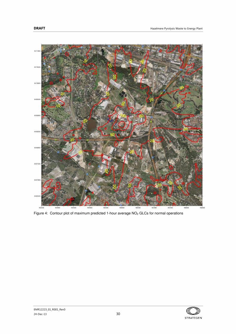
DRAFT Hazelmere Pyrolysis Waste to Energy Plant
EMR12223_01_R001_Rev0
24-Dec-13 30
Figure 4: Contour plot of maximum predicted 1-hour average NO2 GLCs for normal operations

DRAFT Hazelmere Pyrolysis Waste to Energy Plant
EMR12223_01_R001_Rev0
24-Dec-13 31
Table 20: Maximum predicted GLCs at R2 – reduced rate operations
Emission Assessment criteria
(µg/m3)
Average period
Predicted maximum concentration (µg/m
3)
% of assessment criteria
NO2 246.4 1 hour 33 13%
SO2 500 10 min 4.8 1.0%
571.8 1 hour 2.0 0.34%
CO
100000 15 min 101 0.10%
60000 30 min 71 0.12%
30000 1 hour 51 0.17%
VOCs (as TOC)
No criterion N/A 1.1 N/A
HCl 100 1 hour 0.010 0.010%
HF 100 1 hour 0.0034 0.0034%
As 0.09 1 hour 0.00033 0.37%
Cd 0.018 1 hour 0.000003 0.016%
Co No criterion 1 hour 0.0000000049 N/A
CrIII 10 1 hour 0.0000078 0.00008%
CrVI
No criterion 1 hour 0.00000078 N/A
Cu No criterion 1 hour 0.000010 N/A
Hg 1.8 1 hour 0.0000054 0.00030%
Mn 18 1 hour 0.000000000010 0.000000000054%
Ni 0.18 1 hour 0.0000061 0.0034%
Pb No criterion 1 hour 0.000005 N/A
Sb 9 1 hour 0.00000036 0.0000040%
Tl 1 1 hour 0.0000061 0.0006%
V No criterion 1 hour 0.000000024 N/A
TSP No criterion 1 hour 0.14 N/A
PM10 No criterion 1 hour 0.14 N/A
PM 2.5 No criterion 1 hour 0.14 N/A
Dioxins (TEQ)
0.000001 1 hour 0.00000000046 0.046%

DRAFT Hazelmere Pyrolysis Waste to Energy Plant
EMR12223_01_R001_Rev0
24-Dec-13 32
Figure 5: Contour plot of maximum predicted 1-hour average NO2 GLCs for reduced rate operations

DRAFT Hazelmere Pyrolysis Waste to Energy Plant
EMR12223_01_R001_Rev0
24-Dec-13 33
Table 21: Maximum predicted GLCs at R2 – bypass operations
Emission Assessment criteria
(µg/m3)
Average period Predicted maximum
concentration (µg/m3)
Percentage of assessment criteria
NO2 246.4 1 hour 11 4.6%
SO2 500 10 min 6.8 1.4%
571.8 1 hour 1.9 0.33%
CO
100000 15 min 15 0.015%
60000 30 min 11 0.018%
30000 1 hour 5.2 0.017%
VOCs (as TOC) No criterion N/A 0.50 N/A
HCl 100 1 hour 0.0026 0.0026%
HF 100 1 hour 0.0049 0.0049%
As 0.09 1 hour 0.042 47%
Cd 0.018 1 hour 0.0027 15%
Co No criterion 1 hour 0.0000047 N/A
CrIII 10 1 hour 0.0075 0.08%
CrVI No criterion 1 hour 0.00075 N/A
Cu No criterion 1 hour 0.0094 N/A
Hg 1.8 1 hour 0.000070 0.0039%
Mn 18 1 hour 0.0000000093 0.000000052%
Ni 0.18 1 hour 0.0024 1.31%
Pb No criterion 1 hour 0.0047 N/A
Sb 9 1 hour 0.000046 0.00052%
Tl 1 1 hour 0.0024 0.24%
V No criterion 1 hour 0.0000047 N/A
TSP No criterion 1 hour 4.1 N/A
PM10 No criterion 1 hour 4.1 N/A
PM2.5 No criterion 1 hour 4.1 N/A
Dioxins (TEQ) 0.000001 1 hour 0.00000000036 0.036%

DRAFT Hazelmere Pyrolysis Waste to Energy Plant
EMR12223_01_R001_Rev0
24-Dec-13 34
Results from dispersion modelling – cumulative impact assessment
A cumulative impact assessment has been conducted using the background concentration data (Table 18)
and the maximum predicted GLCs for direct impacts of the facility.
The results of the cumulative impact assessment for continuous normal operations (Scenarios 1 and 2) are
presented in Table 22, the reduced rate operations (Scenario 3) is presented in Table 23 and the bypass
operations (Scenarios 4 and 5) is presented in Table 24
No exceedances of the respective air quality criteria are predicted where the emissions from the proposed
WWTE plant operating under any scenario are combined with background concentrations.
Conclusions– direct and cumulative impact assessments
The direct and cumulative air quality impact assessments have shown that acceptable air quality outcomes
are predicted for the proposed WWTE plant at Hazelmere. In particular, no exceedances of air quality
criteria are predicted for direct impacts of air emissions and from cumulative impacts when the emissions
combine with background concentrations of pollutants.
Overall, the assessment has indicated acceptable air emissions impacts can be provided under normal
operations, reduced rate operations (including start-up and controlled shutdown) and bypass conditions
that may accompany rapid shut-down in the event of process outage.

DRAFT Hazelmere Pyrolysis Waste to Energy Plant
EMR12223_01_R001_Rev0
24-Dec-13 35
Table 22: Maximum predicted GLCs at R2 – cumulative impact assessment for continuous normal
operations
Emission Assessment criteria
(µg/m3)
Average period Predicted maximum
concentration (µg/m3)
% of assessment criteria
NO2 246.4 1 hour 95 39%
61.6 Annual 4.4 7%
SO2
500 10 min 26 5.2%
571.8 1 hour 21 3.7%
228.7 24 hour 20 8.8%
57.2 Annual 1.1 2.0%
CO
100000 15 min 680 0.68%
60000 30 min 601 1.0%
30000 1 hour 560 1.9%
11249 8 hour 444 4.0%
VOCs (as TOC) No criterion N/A N/A N/A
HCl 100 1 hour 30 30%
HF 100 1 hour 5.0 5.0%
As 0.09 1 hour 0.011 12%
0.003 Annual 0.0010 34%
Cd 0.018 1 hour 0.0060 33%
0.005 Annual 0.00050 10%
Co 0.1 24 hour 0.010 10%
CrIII 10 1 hour 0.020 0.20%
CrVI
0.0002 Annual 0.000070 35%
Cu 1 24 hour 0.0080 0.80%
Hg 1.8 1 hour 0.0010 0.056%
1 Annual 0.00010 0.010%
Mn 18 1 hour 0.040 0.22%
0.15 Annual 0.0030 2.0%
Ni 0.18 1 hour 0.010 5.6%
0.003 Annual 0.0010 33%
Pb 0.5 Annual 0.020 4.0%
Sb 9 1 hour 0.010 0.11%
Tl 1 1 hour 0.010 1.0%
0.1 Annual 0.0010 1.0%
V 1 24 hour 0.0080 0.80%
TSP 90 24 hour 32 36%
PM10 50 24 hour 20 40%
PM 2.5 25 24 hour 6.1 25%
8 Annual 1.0 13%
Dioxins (TEQ) 0.000001 1 hour 0.00000048 48%

DRAFT Hazelmere Pyrolysis Waste to Energy Plant
EMR12223_01_R001_Rev0
24-Dec-13 36
Table 23: Maximum predicted GLCs at R2 – cumulative impact assessment for reduced rate operations
Emission Assessment criteria
(µg/m3)
Average period Predicted maximum
concentration (µg/m3)
% of assessment criteria
NO2 246.4 1 hour 63 26%
SO2 500 10 min 23 4.6%
571.8 1 hour 20 3.5%
CO
100000 15 min 581 0.58%
60000 30 min 531 0.9%
30000 1 hour 511 1.7%
VOCs (as TOC) No criterion N/A N/A N/A
HCl 100 1 hour 30 30%
HF 100 1 hour 5.0 5.0%
As 0.09 1 hour 0.010 11%
Cd 0.018 1 hour 0.0060 33%
Co No criterion 1 hour 0.010 N/A
CrIII 10 1 hour 0.020 0.20%
CrVI
No criterion 1 hour 0.000071 N/A
Cu No criterion 1 hour 0.0080 N/A
Hg 1.8 1 hour 0.0010 0.056%
Mn 18 1 hour 0.040 0.22%
Ni 0.18 1 hour 0.010 5.6%
Pb No criterion 1 hour 0.020 N/A
Sb 9 1 hour 0.010 0.11%
Tl 1 1 hour 0.010 1.0%
V No criterion 1 hour 0.0080 N/A
TSP No criterion 1 hour 32 N/A
PM10 No criterion 1 hour 20 N/A
PM 2.5 No criterion 1 hour 6.1 N/A
Dioxins (TEQ) 0.000001 1 hour 0.00000048 48%

DRAFT Hazelmere Pyrolysis Waste to Energy Plant
EMR12223_01_R001_Rev0
24-Dec-13 37
Table 24: Maximum predicted GLCs at R2 – cumulative impact assessment for bypass operations
Emission Assessment criteria
(µg/m3)
Average period Predicted maximum
concentration (µg/m3)
% of assessment criteria
NO2 246.4 1 hour 41 17%
SO2 500 10 min 25 5.0%
571.8 1 hour 20 3.5%
CO
100000 15 min 495 0.50%
60000 30 min 471 0.78%
30000 1 hour 465 1.6%
VOCs (as TOC) No criterion N/A N/A N/A
HCl 100 1 hour 30 30%
HF 100 1 hour 5.0 5.0%
As 0.09 1 hour 0.052 58%
Cd 0.018 1 hour 0.0087 49%
Co No criterion 1 hour 0.010 N/A
CrIII 10 1 hour 0.028 0.28%
CrVI
No criterion 1 hour 0.00082 N/A
Cu No criterion 1 hour 0.017 N/A
Hg 1.8 1 hour 0.0011 0.059%
Mn 18 1 hour 0.040 0.22%
Ni 0.18 1 hour 0.012 22%
Pb No criterion 1 hour 0.025 N/A
Sb 9 1 hour 0.010 0.11%
Tl 1 1 hour 0.012 1.24%
V No criterion 1 hour 0.0080 N/A
TSP No criterion 1 hour 36 N/A
PM10 No criterion 1 hour 24 N/A
PM2.5 No criterion 1 hour 10 N/A
Dioxins (TEQ) 0.000001 1 hour 0.00000048 48%

DRAFT Hazelmere Pyrolysis Waste to Energy Plant
EMR12223_01_R001_Rev0
24-Dec-13 38
5.3.7 Commissioning
Commissioning program
A staged commissioning program is planned following completion of construction and individual systems
testing. The program will involve the following activities:
Cold commissioning
This involves operation of all mechanical, electrical and control systems to ensure specified functionality
can be achieved without production of syngas. The kiln burners, SACTO and gas engines would not be
operating during cold commissioning.
Hot commissioning – natural gas fuel
This essentially replicates the first stage of the start-up process, when the pyrolysis kiln burners and the
SACTO are operated on natural gas. The gas engines would also be commissioned on natural gas to
generate electricity for testing of the export systems to the Western Power grid.
Hot commissioning – syngas fuel
This part of the commissioning involves introduction of wood feed to the pyrolysis kiln to generate syngas.
All systems will be on-line during this stage of commissioning that tests the performance of the facility
under normal operating conditions.
Hot commissioning – syngas emergency bypass
At some point during hot commissioning using syngas fuel, a test of the emergency bypass system will be
carried out. A manual bypass event will be initiated to direct raw syngas direct to the SACTO as would
occur during an emergency bypass event. The operation of the SACTO under maximum load conditions
will be assessed during bypass commissioning.
Process optimisation
A program of process optimisation testing will follow successful commissioning of the facility. Key aspects
include optimisation of the syngas production rate with the gas engine demand, optimisation of scrubber
pH and flow rate, and operation of the reformer. Once those processes are optimised, emissions testing
will be carried out from the main stack and gas engine exhausts to confirm the emissions predictions in the
works approval under normal operating conditions. Those emissions data will also be used to support the
application for an environmental licence for commercial operations.
5.3.8 Plume rise assessment
The location of the main stack for the proposed WTE facility at EMRC Hazelmere site is in the flight path to
runway 06/24 at Perth Airport. A plume rise assessment was therefore conducted of the main stack to
assess the potential hazard to aviation posed by a vertical exhaust plume following methodology published
by CASA (2004) and the revised guidelines published in 2012 (CASA 2012).5
A summary of the results of
that assessment is presented below with full details reported elsewhere (Strategen 2013b).
The assessment has shown that plumes from the stack could exceed the Critical Plume Velocity (CPV) of
4.3 m/s at the Obstacle Limiting Surface (OLS) of 60 m with a Critical Plume Height (CPH) of 86 m as
illustrated by the blue plots in Figure 6. However, exceedances of the CPV would only occur under
specific meteorological conditions of fast moving (vertical) air which would transport the stack emissions as
a narrow plume of no more than 3 m in diameter from the point of discharge. The average plume velocity
reaches a maximum of 3.8 m/s at 24 m above ground level (Green plot in Figure 6).
5
The exhaust stacks from the gas engines were not assessed since they will be of lower height than the main stack

DRAFT Hazelmere Pyrolysis Waste to Energy Plant
EMR12223_01_R001_Rev0
24-Dec-13 39
Figure 6: Vertical velocity at plume centre vs height above ground level
Importantly, the probability of the plume vertical velocity exceeding the CPV at and above the OLS height
of 60 m is very low, being 0.0024% which is equivalent to 12.8 minutes per year. Under those conditions,
the maximum velocity predicted at the OLS is 4.9 m/s.
Closer examination of the locations of the stack and runway shows the stack is 3.26 km from the
commencement of the runway, which is 260 m into the second OLS section (Figure 7). That section has a
slope of 2.5% which indicates that the actual OLS commences at an altitude of 66 m at the location of the
stack. This further reduces the likelihood of plume vertical velocities in excess of the CPV and as such the
discharge of air emissions from the 18.3 m main stack at the site is not expected to pose a significant
hazard to aviation.

DRAFT Hazelmere Pyrolysis Waste to Energy Plant
EMR12223_01_R001_Rev0
24-Dec-13 40
Figure 7: Approach surfaces for Perth Airport runway 06/24
5.4 Odour emissions
Significant odour emissions are not expected from the WWTE plant. Air emissions from the main stack
and gas engine exhausts are predominately products of combustion of hydrogen and carbon monoxide,
which are carbon dioxide and water. Other emissions include nitric oxide (NO) which has no odour and
trace levels of sulfur dioxide. The levels of sulfur dioxide in the ambient air are predicted to be well below
the threshold where odour is detected.
A small amount of odour may be present in the air headspace in the scrubber water surge tank from
hydrocarbons which may separate from the water, as well as free ammonia and hydrogen sulfide that will
be released from the ammonium and hydrosulfide ions in solution. The pH of the scrubber water will be
optimised to maximise the solubility of these gases and keep them within solution. In addition, pressure
relief for the tank headspace gases will be via a carbon filter to capture any odours.
The handling and stockpiling practices for the wood feed material for the WWTE plant will not result in the
formation of fugitive odours. In particular, wood stockpiles would be processed at a rate that would
preclude rotting of the wood when wet during the winter months.
The product bio-char material from the pyrolysis kiln will have a similar odour to briquettes used for
domestic BBQs. The char will be stored in covered bins and bagged and exported from the site at regular
intervals such that any odours from char handling would not impact on locations outside the facility.
Runway 06/24
OLS first section
OLS second section

DRAFT Hazelmere Pyrolysis Waste to Energy Plant
EMR12223_01_R001_Rev0
24-Dec-13 41
5.5 Wastewater disposal
The WWTE plant is anticipated to use approximately 5 ML/day of water for cooling the gas engines, to
quench bio-char and for use in the scrubber.
A water balance is being prepared and this will be provided when it has been completed. The water
balance will outline the amount of wastewater expected to be disposed from the site, which in turn will
define the appropriate method of wastewater disposal and allow for the design of the holding tank before
disposal. The holding (storage) tank would be designed to hold the wastewater for up to five days before
requiring disposal.
The process of wastewater disposal may be further refined after the water balance has been undertaken,
but it is expected that water will be recycled in the process and any effluent would be treated as industrial
waste, and disposed of to a licensed facility. Discussions are ongoing relating to the disposal via a
neighbouring Water Corp tradewaste connection point to the reticulated wastewater network.
5.6 Groundwater management
The depth to groundwater at the site is considered to be shallow (within 1.5 m of the ground surface) and
the direction of groundwater flow is north westerly (JDSi 2013).
Dewatering will be required during construction and will have a temporary drawdown effect on the local
groundwater. It is currently envisaged that dewatering will be limited to deep service trenches given the
expectation of imported fill across the site based on the required finished floor levels of building pads.
During operation, groundwater may be used in the process (dependent upon the quality of the abstracted
water) together with scheme water. If groundwater is proposed to be used, a licence under the Rights in
Water and Irrigation Act 1914 will be sought when the amount of water to be abstracted is known (final
water requirement yet to be undertaken).
5.6.1 Acid Sulphate Soils
There is a risk of exposing Acid Sulphate Soils (ASS) as the site has a combination of low to moderate and
moderate to high risk of ASS occurring within 3 m of the natural soil surface, according to DER ASS
mapping.
Geotechnical investigations are yet to be undertaken to understand the extent of excavations required for
construction; however, ASS management are expected to be required for deep service excavations (such
as a sewer). Deep service excavations are not proposed for the WWTE plant.
If deep excavations are required, further detailed ASS studies will be undertaken prior to development to
determine the presence and extent of ASS. From the ASS studies, a management plan would be
developed for both soils and water associated with dewatering.
5.6.2 Contamination
Four sets of nested groundwater monitoring bores were installed at the Hazelmere facility in November
2012 to determine background groundwater quality and obtain baseline data before the expansion of
operations. To date, monitoring data indicates groundwater in the deeper aquifer is uncontaminated but
localised surface contamination has been detected from a source beyond the site boundary. Routine
groundwater monitoring has been implemented to confirm and track these results. Monitoring will continue
through for the WWTE plant.
DRAFT Hazelmere Pyrolysis Waste to Energy Plant
EMR12223_01_R001_Rev0
24-Dec-13 42
5.7 Fire risk
Fire is a hazard to this plant. Dust may pose a fire hazard where an atmosphere arises containing an air-
fuel mix within explosive limits. This may occur with regards to dust from wood waste, dust from bio-char
and from syngas (both prior to cleaning and after cleaning). Explosive limits for dust from wood waste
have not been characterised; however, limits will be influenced by the moisture content of the feed material
(dependant on age) and particle size (Anergy 2012b). Increased moisture content and larger particles
have a diminished risk of ignition.
Hazards posed by wood waste dust will be managed by preventing ignition sources in the area and
selecting appropriate instruments for within the feed bin. Hazards posed by bio-char dust will be managed
via a quenching system proposed as the bio-char exits the kiln.
Fire risks will be managed using a firewater system designed and incorporated into the plant layout. The
firewater system consists of a dedicated firewater tank, two dedicated firewater pumps, each of a different
fuel type (diesel/ electric). Firewater mains will be reticulated around the plant, with hose reels at
appropriate locations and hydrants along plant boundaries.
5.8 Traffic Management
5.8.1 Onsite traffic
The plant employs vehicles in the form of light vehicles, forklifts equipment, trucks and front-end loaders,
as well as requiring pedestrian traffic within the plant boundary.
Traffic within the site will be managed by plant design, whereby the front-end loader movement will be
restricted to a single area near the feed bin, and further engineering controls such as bollards may also be
employed here. Forklift traffic will be restricted to the site perimeter for movement of char and activated
carbon. Light vehicle and truck traffic through the centre of the site will be restricted to maintenance
periods. Procedures and permits shall be employed to managed traffic during these times.
Qualified personnel will be required to employ appropriate PPE as directed by procedures, signage and
plant safety protocols.
5.8.2 Offsite traffic
Stakeholder consultation identified an increase in traffic movements (primarily truck and trailer movements)
as an important factor for the amenity of the area. The proposed route used by trucks and trailers
accessing and leaving the site would be along Lakes Road and Stirling Crescent to the Roe Highway. This
route may be subject to change over the next three years in accordance with an planned upgrade of
Bushmead Road and Lakes Road in conjunction with the extension of Lloyd Street by City of Swan . The
increase in traffic impact has been calculated based on the current proposed road-use.
The WWtE plant is likely to produce around 1500 tonnes of bio-char per year. The bio-char will be trucked
off site either by two 15-tonne trucks or a 30-tonne truck and trailer. This equates to approximately
100 additional trucks per year or 50 additional trucks and trailers per year. On average, two extra truck
movements are anticipated per week from the WtE plant.
Current movements to the Hazelmere facility average around 35 truck movements per day, or
175 movements per week (based on a five day week). Potentially, the count could increase by two trucks
per week, which gives 177 movements per week on average. This is an increase of just over 1% of traffic
from the Hazelmere facility.
Counts from 2008–2009 show that Bushmead Road east of West Parade was used by 6810 vehicles per
weekday on average, having increased from 6060 in 2006–2007 and 5250 in 2004–2005 (Main Roads WA
2009). Around 144 trucks that use Lakes Road on a daily basis, or 720 movements per week (based on a
five day week). The increase of two trucks per week equates to an increase of around 0.3%.

DRAFT Hazelmere Pyrolysis Waste to Energy Plant
EMR12223_01_R001_Rev0
24-Dec-13 43
6. Further information for EPA referral
6.1 Alignment with EPA recommendations (EPA Report 1468)
EMRC has referred the Proposal to the EPA with a view to obtaining a Level of Assessment (LOA) of Not
Assessed, Managed under Part V of the AP Act. EMRC believes that this LOA is appropriate as the
Proposal is anticipated to conform with the recommendations in the EPA (2013) report on Waste to Energy
plants in Western Australia, the Environmental and health performance of waste to energy technologies.
These recommendations are outlined in Table 25. Therefore, a Works Approval and Licence to Operate
under Part V of the EP Act are believed to represent adequate means for assessing and regulating the
potential environmental effects of the Proposal.
Table 25: EPA recommendations for waste to energy technologies
Recommendation Response
Reference within supporting document
1 Given the likely community perception and concern about waste to energy plants, a highly precautionary approach to the introduction of waste to energy plants is recommended.
EMRC is engaging in stakeholder consultation and will use best practice technology, including managing emissions using best practice methods (i.e. continuous monitoring).
EMRC has committed to restricting feedstock to waste wood, with no intention to process trees for wood chipping. Products such as MDF or laminated chip board are not proposed to be used in the process.
Section 2.5
2 As part of the environmental assessment and approval, proposals must address the full waste to energy cycle - from accepting and handling waste to disposing of by-products, not just the processing of waste into energy.
EMRC has accounted for each of the five life-cycle components in feasibility studies.
Waste wood material proposed as feedstock is currently reprocessed as woodchips for a limited market – diversion for electricity production is preferable to disposal to landfill.
Process water can be recycled for reuse onsite.
Solid waste (bio-char) has a potential market as soil and compost additive, and as a solid fuel.
3 Waste to energy proposals must demonstrate that the waste to energy and pollution control technologies chosen are capable of handling and processing the expected waste feedstock and its variability on the scale being proposed. This should be demonstrated through reference to other plants using the same technologies and treating the same waste streams on a similar scale, which have been operating for more than twelve months.
The main comparable plant is the Ansac pilot plant, which has been subjected to extensive trials on the pyrolysis process and gas clean-up system to determine the performance of the proposed technology using several different feedstocks.
Other WTE technologies being implemented or proposed in WA include gasification and anaerobic digestion at Red Hill Resource Recovery Facility (EMRC), and gasification at Boodarie at East Rockingham (NEC).
EMRC have engaged the Centre for Energy at UWA to provide an independent evaluation of proposed engineering designs and drawings to ensure the plant will meet its process and energy generation objectives.
Premier Coal Char Plant is also a comparable plant that uses pyrolysis of coal, other international reference facilities include Canada (110 000 tpa green biomass to fuel oil and syngas) and Malaysia (15 000 tpa biomass to fuel oil and syngas),
Section 1.2

DRAFT Hazelmere Pyrolysis Waste to Energy Plant
EMR12223_01_R001_Rev0
24-Dec-13 44
Recommendation Response
Reference within supporting document
4 Waste to energy proposals must characterise the expected waste feedstock and consideration made to its likely variability over the life of the proposal.
Variability of feedstock has not been extensively investigated; however, the physical processing of other waste materials would be possible using the current technology. EMRC has investigated the suitability of wood chip feedstock from softwood, hardwood and mixtures thereof. Ansac has also trialled other feedstocks including refuse derived fuel (RDF).
Section 4.5
5 The waste hierarchy should be applied and only waste that does not have a viable recycling or reuse alternative should be used as feedstock.
Conditions should be set to require monitoring and reporting of the waste material accepted over the life of a plant.
The Hazelmere site diverts untreated timber from landfill and converts it to useable wood chip and woodfine products. This process will use part of the wood chip to generate renewable power and bio-char.
This document outlines the proposed feed of the
WWTE plant in Table 5 which is in line with the criteria that is already in place at the Hazelmere Recycling Centre (http://www.emrc.org.au/acceptance-criteria.html)
Section 4.1
6 Waste to Energy operators should not rely on a single residual waste stream over the longer term because it may undermine future recovery options.
EMRC has investigated the suitability of woodchip feedstock from softwood, hardwood and mixtures thereof. Ansac has also trialled other feedstocks including refuse derived fuel (RDF). The feasibility of converting greenwaste from member Councils to bio-char will be investigated by the EMRC.
Section 4.5
7 Regulatory controls should be set on the profile of waste that can be treated at a waste to energy plant. Plants must not process hazardous waste.
Hazardous waste will not be processed. This document outlines the proposed feed of the
WWTE plant in Table 5 which is in line with the criteria that is already in place at the Hazelmere Recycling Centre (http://www.emrc.org.au/acceptance-criteria.html)
Section 1.2
8 In order to minimise the discharge of pollutants, and risks to human health and the environment, waste to energy plants should be required to use best practice technologies and processes. Best practice technologies should, as a minimum and under both steady state and non-steady state operating conditions, meet the equivalent of the emissions standards set in the European Union’s Waste Incineration Directive (2000/76/EC).
Air emission investigations have been undertaken and include the provision to meet the emission standards in the European Union’s Waste Incineration Directive (WID) emission criteria (2000/76/EC).
Section 5.3
9 Pollution control equipment must be capable of meeting emissions standards during non-standard operations.
Air emission investigations have been undertaken and have investigated the capability of the pant during non-standard conditions (i.e. reduced rate and bypass conditions.
Section 5.3

DRAFT Hazelmere Pyrolysis Waste to Energy Plant
EMR12223_01_R001_Rev0
24-Dec-13 45
Recommendation Response
Reference within supporting document
10 Continuous Emissions Monitoring must be applied where the technology is feasible to do so (e.g. particulates, TOC, HCl, HF, SO2, NOx, CO). Non-continuous air emission monitoring shall occur for other pollutants (e.g. heavy metals, dioxins and furans) and should be more frequent during the initial operation of the plant (minimum of two years after receipt of Certificate of Practical Completion). This monitoring should capture seasonal variability in waste feedstock and characteristics. Monitoring frequency of non-continuously monitored parameters may be reduced once there is evidence that emissions standards are being consistently met.
As the predicted air emissions are anticipated to be under threshold limits for all operating scenarios, monitoring is not considered to be required.
Emissions testing will be carried out during commissioning from the main stack and gas engine exhausts to confirm the emissions predictions under normal operating conditions.
Section 5.3
11 Background levels of pollutants at sensitive receptors should be determined for the Environmental Impact Assessment process and used in air dispersion modelling. This modelling should include an assessment of the worst, best and most likely case air emissions using appropriate air dispersion modelling techniques to enable comparison of the predicted air quality against the appropriate air quality standards. Background monitoring should continue periodically after commencement of operation.
Air emission investigations have been undertaken and have established background levels that were used in the assessment.
Section 5.3
12 To address community concerns, proponents should document in detail how dioxin and furan emissions will be minimised through process controls, air pollution control equipment and during non-standard operating conditions.
Air emission investigations have been undertaken and have investigated dioxin and furan emissions to establish potential levels and inform project design. Dioxins/furans will have been removed from the clean syngas in the reformer and scrubber, and are not considered to be present at levels of concern.
Section 5.3
13 Proposals must demonstrate that odour emissions can be effectively managed during both operation and shut-down of the plant.
Odour emissions are not expected to be an issue for the WWTE plant as the wood waste is not generally an odorous waste. Also measures to ensure that the feed and any water in holding tanks, etc., will not become odorous will be put in place during operations.
Section 5.4
14 All air pollution control residues must be characterised and disposed of to an appropriate waste facility according to that characterisation.
Cleaning of the syngas is conducted using a char bed. Tar compounds, dust, remaining tars and excess moisture are removed using a steam reforming catalyst (exact catalyst yet to be determined), with oxygen used to maintain the necessary heat for the reaction. The char bed material will be treated or disposed of using an appropriate waste facility.
Section 5.3
15 Bottom ash must be disposed of at an appropriate landfill unless approval has been granted to reuse this product.
Bottom ash (bio-char) will be disposed offsite unless it can be sold as a by-product fuel or soil amendment/carbon farming additive.
16 Any proposed use of process bottom ash must demonstrate the health and environmental safety and integrity of a proposed use, through characterisation of the ash and leachate testing of the by-product. This should include consideration of manufactured nanoparticles.
Extensive research has been undertaken in the bio-char area to establish the health and environmental aspects of this material. As the bio-char is produced from clean wood waste feed and not from incineration or gasification, it is unlikely to contain a high level of contaminants. For example, bio-char can be used as a soil amendment as it improved soil health characteristics such as improving water retention and enhanced earthworm attraction.

DRAFT Hazelmere Pyrolysis Waste to Energy Plant
EMR12223_01_R001_Rev0
24-Dec-13 46
Recommendation Response
Reference within supporting document
17 Long term use and disposal of any by-product must be considered in determining the acceptability of the proposed use.
As above.
18 Standards should be set which specify the permitted composition of ash for further use.
As above.
19 Regular composition testing of the by-products must occur to ensure that the waste is treated appropriately. Waste by-products must be tested whenever a new waste input is introduced.
As above.
20 Waste to energy plants must be sited in appropriate current or future industrial zoned areas with adequate buffer distances to sensitive receptors. Buffer integrity should be maintained over the life of the plant.
The plant is to be located on industrially zoned land which will incorporate sufficient buffering distances from sensitive receptors.
Section 2.2.1
21 For a waste to energy plant to be considered an energy recovery facility, a proposal must demonstrate that it can meet the R1 Efficiency Indicator as defined in WID.
Efficiency is expected to be better than, or similar to, that of the Red Hill Resource Recovery Facility. For that facility, efficiency was expected to be approximately 0.59. Increasing efficiency to the European Union WID standard of 0.65 would have required higher steam pressures which was considered, in EMRC opinion, to be infeasible for Western Australian conditions; the EPA accepted this in its Report and Recommendations (Report 1487) of July 2013 for the facility.
As the Hazelmere pyrolysis plant has a pure feedstock and is true pyrolysis, there is no oxygen or nitrogen present in the syngas and, with direct injection into gas engines, the energy efficiency is expected to be high.
6.2 Significance test
In reaching a decision as to whether a proposal is likely to have a significant effect on the environment,
whether it is likely to meet its objectives for environmental factors and consequently, whether a referred
proposal should be assessed under Part IV of the EP Act, the EPA may have regard to the following:
• values, sensitivity and quality of the environment which is likely to be affected
• extent (intensity, duration, magnitude and geographic footprint) of the likely impacts
• consequence of the likely impacts (or change)
• resilience of the environment to cope with the impacts or changes
• cumulative impact with other projects
• level of confidence in the prediction of impacts and the success of proposed mitigation
• objectives of the Act, policies, guidelines, procedures and standards against which a proposal can
be assessed
• presence of strategic planning framework
• presence of other statutory decision-making processes which regulate the mitigation of the
potential effects on the environment to meet the EPA objectives and principles for EIA
• public concern about the likely effect of the proposal, if implemented, on the environment.
A significance test for the proposal has been undertaken against each of these criteria as outlined in
Table 26

DRAFT Hazelmere Pyrolysis Waste to Energy Plant
EMR12223_01_R001_Rev0
24-Dec-13 47
Table 26: Significance test (EPA referral)
Criteria Assessment
Values, sensitivity and quality of the environment which is likely to be impacted
The main land uses in the area are for industrial purposes. The Proposal will not affect any environmentally significant areas or land features.
There is no vegetation within the Proposal area and therefore, it is not anticipated that any TECs or PECs or Threatened flora would be affected.
The site is not expected to provide habitat for native fauna species, thus it is not anticipated that native fauna would be affected.
Extent (intensity, duration, magnitude and geographic footprint) of the likely impacts
Consequence of the likely impacts (or change)
Resilience of the environment to cope with the impacts or changes
The plant will cover approximately 0.2 ha. The proposal area is located on highly degraded land. Project life is expected to be 25 years.
The overall effects of the Proposal are not expected to be significant at a local or regional level.
Cumulative impact with other projects
Cumulative impacts are not expected as, although other industrial land uses surround the site, this plant is the only one of its type proposed for the area.
Level of confidence in the prediction of impacts and the success of proposed mitigation
The environmental impacts of the Proposal will be addressed through management measures within a proposed EMP which will address air emissions, wastewater disposal, groundwater monitoring and dust monitoring.
Objects of the Act, policies, guidelines, procedures and standards against which a proposal can be assessed
The project can be assessed against the EPA Report 1468 which outlines EPA position on environmental and health performance of waste to energy technologies (EPA 2013).
An analysis of the recommendations in the EPA (2013) report is located in Table 25 of this document.
Presence of strategic planning framework
Hazelmere Enterprise Area Structure Plan (City of Swan 2011).
Presence of other statutory decision-making processes which regulate the mitigation of the potential effects on the environment to meet the EPA objectives and principles for EIA
A number of key regulatory controls can be applied to the Project to ensure appropriate management includes (but is not limited to):
• conditions of a Works Approval issued under Part V of the EP Act for construction of works on prescribed premises
• conditions of Licence to Operate issued under Part V of the EP Act for the operation of activities on prescribed premises.
Public concern about the likely effect of the proposal, if implemented, on the environment
There is some public concern regarding increased traffic around the plant; however, traffic is unlikely to increase significantly for the proposal (two additional trucks per week compared with current conditions).
Stakeholder consultation has been undertaken in July 2013 and will continue as required.

DRAFT Hazelmere Pyrolysis Waste to Energy Plant
EMR12223_01_R001_Rev0
24-Dec-13 48
7. References
Anergy 2012a, Plant design specification - Waste to Energy Plant, unpublished report prepared for EMRC
(commercial in confidence).
Anergy 2012b, Eastern Metropolitan Regional Council Waste-To-Energy Plant Engineering Report,
unpublished report prepared for EMRC (commercial in confidence).
Ansac 2013, Ansac offered clean technology innovation programme grant, [Online], Ansac, Available from:
<http://www.ansac.com.au/2013/07/ansac-offered-clean-technology-innovation-programme-grant/>
[5 December 2013].
City of Swan 2011, Hazelmere Enterprise Area Structure Plan, prepared for City of Swan and the
Department of Planning, September 2011.
City of Swan 2013, City of Swan Local Planning Strategy prepared in conjunction with Local Planning
Scheme No. 17, [Online], Western Australian Planning Commission, Available from:
<http://www.planning.wa.gov.au/localplanningstrategies/3527.asp> [22 October 2013].
Department of Environment and Conservation (DEC) NSW 2005, Approved Methods for modelling and
assessment of air pollutants in New South Wales, New South Wales Department of Environment and
Conservation, Sydney, NSW.
Department of Environmental Regulation (DER) 2006, Air Quality Modelling Guidance Notes, Department
of Environment, March 2006.
Department of Health (DOH) 2007, Acid Gas Criteria, Internal document, Toxicology WA Department of
Health, Shenton Park, WA.
Department of Health (DOH) 2011. Esperance Ni annual guideline value, personal communication from Ms
Mirella Goetzmann, Department of Health. May 2011.DEC WA 2011. Background Air WQUalirt (Air
Toxics) Study, Heavy metals Perth Metropolitan Area. Available from: <
http://portal.environment.wa.gov.au/portal/page?_pageid=54,3558366&_dad=portal&_schema=POR
TAL > [29 September 2011].
Eastern Regional Metropolitan Council (EMRC) 2012, Public Environmental Review. EMRC Resource
Recovery Facility Project, prepared by Cardno (WA) Pty Ltd, West Perth, WA.
Eastern Regional Metropolitan Council (EMRC) 2013a, Annual Report 2012-2013, [Online], EMRC,
Available from: <http://www.emrc.org.au/annual-reports.html> [13 November 2013].
Eastern Regional Metropolitan Council (EMRC) 2013b, Resources – 2010 waste to energy technologies
forum, [Online], EMRC, available from: <http://www.emrc.org.au/resources.html> [14 November
2013].
Eastern Regional Metropolitan Council (EMRC) 2013c, Waste Management Community Reference Group,
[Online], EMRC, Available from: <http://www.emrc.org.au/waste-management-community-reference-
group.html> [14 November 2013].
Eastern Regional Metropolitan Council (EMRC) 2013d, Community Task Force, [Online], EMRC, Available
from: <http://www.emrc.org.au/community-task-force.html> [14 November 2013].
ENVIRON Australia Pty Ltd (Environ) 2013, EMRC Hazelmere Air Dispersion Modelling Assessment,
report prepared for EMRC, Perth, WA.
Environmental Protection Authority (EPA) 2013, Report and recommendations of the Environmental
Protection Authority and the Waste Authority. Environmental and health performance of waste to
energy technologies. Advice of the Environmental Protection Authority to the Minister for Environment
under Section 16(e) of the Environmental Protection Act 1986. Report 1468, April 2013.

DRAFT Hazelmere Pyrolysis Waste to Energy Plant
EMR12223_01_R001_Rev0
24-Dec-13 49
EU 2000. Directive 200/76/EC of the European Parliament and of the council of 4 December 2000 on the
incineration of waste.
EU 2010. Judgement of the Court (Eighth Chamber) of 25 February 2010, Case C-209/09, <http://eur-
lex.europa.eu/LexUriServ/LexUriServ.do?uri=OJ%3AC%3A2010%3A100%3A0009%3A0009%3Aen
%3APDF> [23 December 2013]
JDSi Consulting Engineers (JDSi) 2013, EMRC – Hazelmere Resource Recovery Park, Hazelmere –
Engineering servicing report May 2013, unpublished report prepared for EMRC.
Lloyd George Acoustics 2013, Environmental Noise Assessment, Waste to Energy Facility, Hazelmere,
prepared for EMRC,
Ontario MOE 2008. Ontario’s Ambient Air Quality Criteria, PIBS# 6750e, Standards Development Branch,
Ontario Ministry of the Environment, Toronto, Canada.
NEPC 2003. National Environment Protection (Ambient Air Quality) Measure Variation. National
Environment Protection Council (NEPC). Adelaide, SA.
Strategen Environmental Consultants (Strategen) 2013a. Air emissions inventory - Hazelmere Waste to
Energy project. Draft report, File No. EMR13079_01 R002 Rev B, 18 October 2013.
Strategen Environmental Consultants (Strategen) 2013b. Plume rise assessment - Hazelmere Waste to
Energy project. Draft report, File No. EMR13079_01 R001 Rev B, 22 April 2013.
TCEQ 2011. Texas Commission on Environmental Quality, Effects Screening Levels updated July 2011.
Available from http://www.tceq.texas.gov/agency/data/effectsscreeninglevels.html > August 2011.
Toxikos 2010. Air Guideline Values for Selected Substances, Toxikos for WA Department of Environment
and Conservation, Booragoon, WA.
WA Government 1992. Environmental Protection (Kwinana) (Atmospheric Wastes) Regulations 1992.
Version 01-a0-05, 6 February 2004.
Waste Authority 2012, Western Australian Waste Strategy “Creating the Right Environment”, [Online],
Government of Western Australia, Available from:
<http://www.wasteauthority.wa.gov.au/publications/western-australian-waste-strategy-creating-the-
right-environment> [13 November 2013].
Waste Authority 2013, Waste to Energy Position Statement (Thermal treatment) May 2013, [Online],
Government of Western Australia, Available from:
<http://www.wasteauthority.wa.gov.au/publications/waste-to-energy-statement> [13 November
2013].
Western Australian Planning Commission (WAPC) 2006, Kewdale-Hazelmere integrated masterplan, Final
report August 2006, [Online], State of Western Australia, Available from:
<http://www.planning.wa.gov.au/publications/907.asp> [22 October 2013].
WHO 2000. Air quality guidelines for Europe, Second edition. World Health Organisation – Regional Office
for Europe, Copenhagen, Denmark.
WHO 2005. WHO air quality guidelines for particulate matter, ozone, nitrogen dioxide and sulfur dioxide –
Global update 2005. World Health Organisation, Geneva, Switzerland.

DRAFT Hazelmere Pyrolysis Waste to Energy Plant
EMR12223_01_R001_Rev0
24-Dec-13
Appendices (as attached in CD ROM or in electronic submission in the Industry Licensing System)
Appendix 1: Naturemap database search results
Appendix 2: Environmental Noise Assessment, Lloyd George Acoustics 2013
Appendix 3: Air emissions modelling, ENVIRON 2013