hazardous areas protection techniques · • subject to specific wiring rules to maintain safety...
TRANSCRIPT

HAZARDOUS AREAS
PROTECTION TECHNIQUES
Neil Dennis

Properties of Materials
Flash point & boiling point
Vapour/gas density
Vapour pressure Flammable range
Ignition temperature
Molecular size
Ignition energy +
560
360
310
210
0
100
200
300
400
500
600
Auto Ignition Temperature (Hot Surface)
Deg
rees C
elc
ius
H2 LPG Petrol Kero (Jet)
0
0.5
1
1.5
2
2.5
Ignition Energy mJ
H2 LPG Petrol Kero (Jet)
Less than 2
0.019
Hazardous Area Classification
Electrical Equipment Design

Electrical Equipment – Gas/vapours
Temperature Class
Related to gas/vapour ignition temperature (inversely)
- T1 = 450C
- T2 = 300C
- T3 = 200C
- T4 = 135C
- T5 = 100C
- T6 = 85C
Equipment Group
Factor related to molecular size
Gas/vapour categories:
IIA, IIB and IIC
Sets characteristics for:
- Ability of gas/vapour to pass through small gaps
- Sensitivity to ignition by sparks

Examples: Methane and H2S
Methane H2S
Flash Point: gas gas
Gas density to air: 0.55 1.19
Flammable range: 4.4% – 17% 4% - 44.5%
Ignition Temperature: 600oC 260oC
Temperature class: T1 T3
Safe Flame Gap (MESG) : 1.14mm 0.63mm
Gas Group: IIA IIB

Electrical Ignition
Friction
Chemical reactions
Hot surfaces
Arcs and sparks
Static electricity
Lasers
Used or Created by electrical
equipment
See AS/NZS 60079-14 for requirements

Electrical Equipment - Protection Principles
• Containment (of hot particles)
• Exclusion (of gas/vapour from electrical components)
• Energy limitation (below that required to cause ‘big’ sparks)
• Ignition avoidance (increasing safety factors to avoid conditions that
cause heat or sparks)
• Dilution (capture vapour/gas and remove it)

Flameproof Equipment ‘Ex d’
Oldest technique, Robust equipment but needs to be handled with care.
Flameproof does not mean weatherproof.
Vapour can enter equipment, but if ignited, flames (hot gases) do not leave the enclosure.
Sensitive to ‘gaps’ and surfaces providing controlled release.

Flameproof Equipment - Principles
Gas is cooled below ignition temperature of outside gas
Surfaces cool hot gas on exit Vapour enters
enclosure as it heats up & cools (transpiration)
Electrical equipment may ignite vapour
Explosion forces on lid
Spark
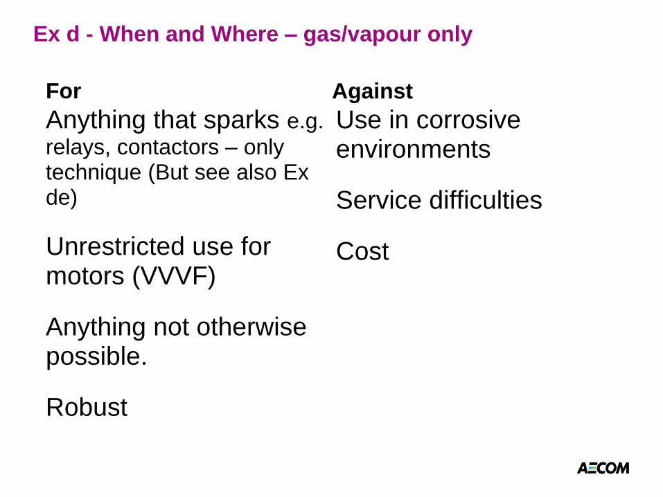
Ex d - When and Where – gas/vapour only
For
Anything that sparks e.g.
relays, contactors – only technique (But see also Ex de)
Unrestricted use for motors (VVVF)
Anything not otherwise possible.
Robust
Against
Use in corrosive environments
Service difficulties
Cost

All bolts in place.
Check cables correctly secured (fully engaged with correct glands)
Ex d - example

Ex d Faults – Surface Finishes
Tolerance to failure for a 25mm flamepath may be as little as 0.01mm (0.4 thousands of an inch)
Calibration label indicates service
technician does not understand flameproof
issues.

Environmental Performance
Equipment should be installed and maintained for environmental performance. (To maintain explosion protection rating)

Increased Safety ‘Ex e’
• ‘Modern’ technique
• Increasing protection factors over conventional industrial equipment for; • Overheating
• Sparks (clearances and creepage distances etc.)
• Not applicable for equipment that creates sparks (e.g. switches)
• Subject to specific wiring rules to maintain safety issues e.g. circuit protection characteristics, derating of cables, termination details.

Ex e Equipment - gas/vapour only
Ex e equipment allows for the use of alternative materials and construction which may be suited to some environments.
OH6/9

Mixed Techniques Ex de
Combinations of explosion protection in one device
Allows for special constructions
Exe Connections
Miniature Exd Switch
OH6/20

Ex e enclosure flexibility

Ex e faults

Ex e - When and Where – gas/vapour only
For
Junction boxes, Lights, Motors
Contactors, circuit breakers etc as Exde)
Style and materials flexibility.
Cost
Against
VVVF and SS rules for motors
Careful selection requirements.
Installation sensitivities
Some limitations

Intrinsic Safety – ‘Ex i’ – Gas/vapour/dust
Low energy technique (too small to create ignition capable sparks).
Three levels of security.
- Exia - Suitable for zone 0/20 (inside tanks)
- Exib - Suitable for zone 1/21
- Exic - Suitable for zone 2/22 only
Secure under recognised fault conditions (Ex ia – 2 faults, Ex ib – 1 fault, Ex ic – no fault tolerance)
Allows freedom in some types of equipment used
Penalty is complex wiring rules and design issues.

Intrinsically Safe Circuit
P=VI E= ½ CV2 E= ½ LI2
All power and energy needs to be accounted for (including wires and electronics).
Calculations need to be recorded
Only certified Intrinsically Safe electronics can be used in I.S. circuits. However switches and LEDs are ‘simple devices’ that do not need certification.
Wire Capacitance
Switch Wire
Inductance I.S. Barrier
Device Inductance & capacitance

‘Zener Barriers’ require special earthing
provisions
‘Transformer Barriers
Safety segregation distances between wiring as part of ‘fault security
I.S. Barriers
Intrinsically Safe ‘Barriers’ allow safe use of equipment in a hazardous area but must be installed outside a hazardous area.

Ex i Faults
Zener Barrier earthing not up to standard
I.S. wiring not segregated from
other wiring.
Labelling and wire numbering required

Ex i - Faults

Ex i - When and Where – gas/vapour/dust
For
Low power devices only (few watts), instruments, LEDs, simple switches and sensors
Zone 0
Style, function and materials flexibility.
Cost
Against
Power limitations
Complex selection and design requirements.
Installation sensitivities

Non Sparking ‘Ex n’ – gas/vapour only
Only allowed for zone 2
Uses increased security, but is close to conventional industrial standards
Can use a number of ‘sub-styles’ for protection
Not preferred for many sites

Ex n - When and Where – gas/vapour only
For
Junction boxes, Lights, Motors, electronics etc.
Style and materials flexibility.
Cost
Against
Zone 2 only
VVVF and SS rules for motors
Careful selection requirements.
Installation sensitivities
Some limitations

Others
Ex td – dust protected; dusts only,
Ex m – encapsulation;
Gas/vapour/dust,
small items only
Ex p – pressurisation;
Gas/vapour/dust
for anything really special or otherwise can’t be done.

Questions or Questionable?