happy snow cruising - elyon school & child care snow cruiser omc eng.pdfyour snow cruiser is...
TRANSCRIPT
l
HAPPY SNOW CRUISING
This Owner's Manual has been prepared to assist you in the operation and maintenance of your new Snow Cruiser. It contain~ information that you should know in order to realize the peak performance and pleasure of operation that has been built into this machine. Read the entire book carefully, then keep it hanny for future reference.
Your Snow Cruiser i s produced umler the finest quality controlled methods and built to give many hours of dependa ble service. Ills our belief that a sale does not complete the transaction between the manufacturer and tile buye1·. It establishes , rather , a new obligation -- an obligation whereby Outboard Ma1·ine Corporation of Canada Ltd. agrees to assist the buyer in obtaining utmost service from his Snow Cruiser .
With this policy uppermost in ou.r minds, we have appointed our most capable Johnson, Evinrude and Lavht- Boy Servi ce Dealers us Snow Cruiser Service Dealers. These p eople are trained and equipped to service your unit. Away from home, authorized 0 . M. C. Service Dealers ' names may be located in the yellow pages of the telephone directory.
Outboard Marine Corporation of Canada L tn., Peterborough, Canana. -
r TABLE OF CONTENTS Page
SPECIF ICATIONS • • • • • • • . . . . • • • • . • • . • 2
ASSEMBLY INSTRUCTIONS -Windshield • • • • • • • • • • . • • • • 3 -Taillight • • • • • • • • • • • . . • • • 3 -:::>kis • • • • • • • • • . . • • . • • . • 3 - Tow Ba:r, Seat Dack & Compartmcn,t : • 3 -Battery. • • • • • . • • • . • • . • . • 3
CONTROLS -Throttle • • • • • 4 -Warm-Up Lever. 1 -Light Switch • • 4 -Neutral Shift • • 4 -Hand Hrake • • 4 - Po.rking Brllltc • 4 - Transmission • 5
HOW TO GR'T' STARTED - B1·eak-In P el'iod . . . . • . . . , • G - Fuel Mixture & Recommendations !'i -Mixing Fuel • . . • 5 -Starting Engine . . 6 -Electric SL<u·Cing 7 -Emergency Starting 7
OP ERATION - Electric Starting Models 7 -Extreme Cold Weather 7 -Uph!ll • • . . • • • 7 -Downhill . • • . • • 7 -Glare Ice . • . . . 7 -Safety Precautions 8
PART No. 404278
GENERAL MAINTENANCE -Ca.rhuretor - Engine Shroud •• ••• . - Battery .•..... .. . . -Chain & Transmission Guard -Gas Tank .......• -Dl'ive Chain Adjustment • - Installi ng Drive Chain . -Brake Adj ustment -Track Tension -Traek AligrunenL
DRIVE BELT REPLACEMENT ••••. • ••••
-Procedure for Installing the Transmission Belt -::>tarter Motor Drive Belt • • -Ski Alignment • • • • • • • • -Off Season Storage • • • . . -After Storing - Before Using
TROTJRT.F. CHECK L IST
SERVICE DIAGNOSIS • •
MAINTENANCE AND LUBRICATIOK
ITEMS OF SPECIAL INTEREST -Repair Service ••••••• -Replacement Parts . . . . . -Owner':; Warranty Certificate • -Where to Find Model & Serial Ntunber
WARRANTY ...••.•.• • . • .• ••
Page
8 9 9 9 9 9
10 10 11 11
12 13 13 11 14 14
14
15-16
16
17 17 17 17
. . ... ~ 18
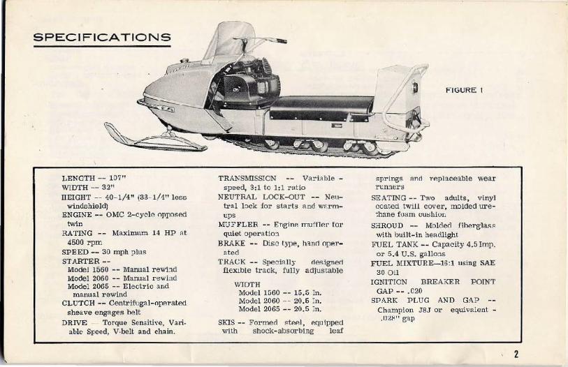
SPECIFICATIONS
LENGTH-- 107" WIDTH-- 32" llEIGHT -- 40-1/4" (33-1/1" less
windshield) ENGINE-- OMC 2-cycle opposed
twin RATING - - Maximum 14 HP A.t
4500 rpm SPEED -- 30 mph plus STARTER--
Model 1560 -- Manual r ewi!ld Model 2060 -- Marrual r ewind Model 2065 -- Elect ric and
manual rewind CLUT CH - - Centrifugal-ope1·ated
sheave engages belt DRIVE - Torque Sensitive, Vari.
able Speed, V-belt and chain.
TRANSMISSION -- Variable -speed, 3:1 to 1:1 ratio
NEUTRAL LOCK-0UT -- Neutral l:)Ck for starts and WP.rmups
MUFFLER -- Engine muffler for quiet opet'atio:~.
BRAKE Disc type, h~JH"l OpAl'-
ated TRACK Speci:l lly rtesigne<i
flexible track, fully adjustable
WIDTH Model 1560 -- 15.5 In. Model 2060 -- 20.6 In. Model 2065 -- 20.5 ln.
SKIS -- Formed steP. I, equipped vnth shock-absorblng leaf
FIGURE I
springs Rnrt replaceable wear run."lers
SEATING-- Two adults , vinyl coated twU! cover, molded urethane foam cu::;hion
SHROUD -- Molded fiherglas~ with built-in headlight
FUEL TANK -- Capacity 4.5 Imp. or 5.4 U.S. gallo:~.s
FUEL MIXTURE-16:1 nsing SAE 30 Oil
IGNITION BREA:<ER POIN1' GAP-- .020
SPARK PLUG AND GAP - Champion JSJ or equivalent -.021'" gap
2

ASSEMBLY
INSTRUCTIONS
All small parts are packed in r e.ar e(}m-er &:tpport of pack.
WINDSHIELD Insert five (5) Rawlnuts (rublJer euveret.l nuts) into screw holes in sh!"oud. Assemt.le i nner llnrl oute:r framP.~ o"\ windshiP.ld, r e d idcntificlltion marks on cide edge o: frames must appear on •.ha left side uf the windshield assembly. Position windshield on shrourl ::lnci align holes. lnsP.l't cP.ntP.r screw f irst, then work to s ides. F ig.1re 2.
FIGURE 2
TAILLIGHT Insent lead on vehicle through hole in se•at hack compartment. Insert split rubber grcmme.t in hole. ConnP.d to taillight le•ad and a-ttach to anchor.
SKIS BlOCk up front end of vehicle. COIUtect both skis as illustrated in Figure 3, using nuts and bolts ?rovided.
FIGURE 3
TOW BAR, SEAT BACK and COMPARTMENT Position Tow Bar and Sea-t Dack Compartmem a-s illus•trat~d i.u Figure 4. F.as.ten in pbace us•ing nuts, Lockwashers and oo·l!>S provided. Fasten ela.stic cord and clamp to sea•t back with screw provided. ·
BATTERY Due to the cxtxcmo wco.ther and temperature conditions under which the JJa ttery must operate, proper battery selection i:s very ir.1.portant. We recommend 8 1 2 volt battery haYing a. 42 ampere hour ro.ting or better, with a minimum of 2.7 rninuLeo cold starting capacity at 150 amperes discharge, zero degrees Fahre:1.he it and 11. !1 second voltage r ating of 8.4 volts.
The following battexies or their equivalent are recommended:
I'rcsto!ite HN-10 Autollte 10-HN Willard 22-NF
IMPORTANT
ln o:rr1P.:r to provide maxim:~m protection from battery acid darmtge in eve:1t of accideutul upset, special spill-proof ba:tery ~aps ll.l'P. supplied with the vehicle. Make certain these special JJa·.tery cuvs a re iuolalled onyouL· battery. See Figure 5.
FIGURE 4
3
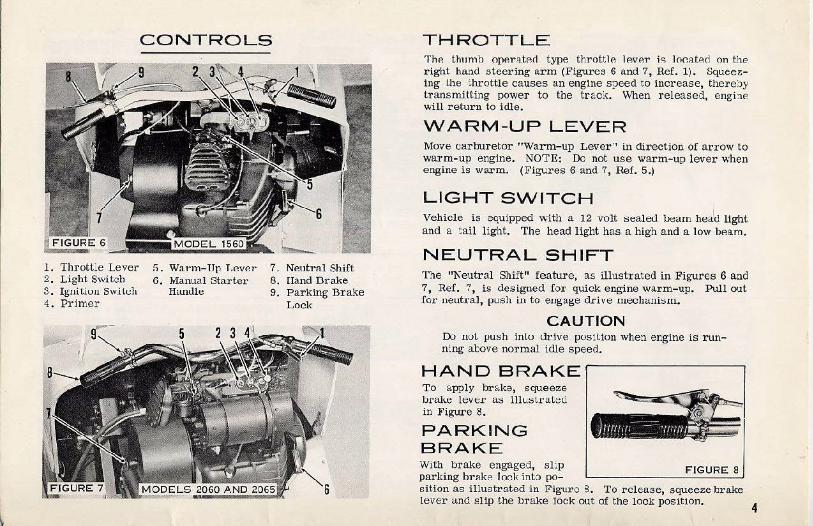
1. Thrott~e Lever 2. Ligh t Switch 3 . Igniliuu Swlich 4. Primer
CONTROLS
5. Warm-Up T.P.ver 6. Manual Starter
Handle
Neutral Shift !land Drake Parking Brake Lock
THROTTLE 'The thumb operat P.ct type throttle lever j,:; lo~fl.ted on the right ha:~.d steering arm (Figures 6 and 7, Ref. 1). Squeez:tng Lhe throttle causes an engine speed to increase, thereby transmitting power to the trac:, . When released, enghe will return to idle.
WARM-UP LEVER Move Cll.r buretor "Warm-up Lever·• in direction of arrow to warm-up engine. NOTE: Do not use warm-up lever when engine is warm. (Figures 6 and 7, Ref. 5.)
LIGHT SWITCH Vehicle i s equipped ''•iith a 12 volt sealed !Jearn heJu light and a tail light. The head light has a high and a low bP.am.
NEUTRAL SHIFT The "Neutral Shift" feature, as illustrated in Figures 6 and 7, Ref. 7, is designed for quick engine warm-up. Pull out for neutral, push in to eugage drive 1!lechani::;m.
CAUTION D:> uoL .fJU::>h inLo drive position when engine is running above normal idle speed.
HAND BRAKE T o apply brake, squeeze b!·ake lever as illustL·ated in Figure 8.
PARKING BRAKE With brake engaged, s l ip FIGURE 8 parking brake lock into po-sition as illustrated in Figure 3. To release, squeeze brake lever and slip the brake lock out of the lock position.
4
CONTROLS CONTINUED TRAN S MISSION The transmission assembly transmits power from the engine t::> the track which propels the Yehicle .
The "Primary Sheave Assembly" atreches directly to the power take off e:1d of the crankshaft. The "~concary Sheave Assemb:y·• has its own mounting base and is larger in diameter than the Prinary Assembly. The two are connected by t.'le ctr:ve belt.
The Pr1mary Sht::L~t:: ill ~.:t::ull'ifugally operated and engages when Fu> P.nginP. !=ipP.ed r eaches approximately 2000 rpm.
As the engine s ;>eed is increased, the Primary 31:eave hnlvcs clo3c forcing the belt to ri::le on the outer diameter of the primary ctrive which increases the belt speed.
At this point the Secondi.i.l'Y ::>hellve halves spread apart, allo·..ving the ·')e lt. to ridG on t.hc ~m::1ll rli.:~.mete:r.
Basically, the vehicle speed increases due to the power being t::-ansruitted fro m lhe primary pulley to the secondary d.L'i ve rnechani Slll.
The secondary drive mechanism incorpor ates a torque sensitive devicl~ that allows automatic s hirting to a lower gear ratlo fur steep lnt:lln~s .
The:: )Jl'lmary a ssembly is equipped with an emergency .starting s hea\'e and a neutral shift mechanism, both of which Rre coVP.l'Arl in othP.r parts of this Manual. As :;talt::tl u11 ~Itt: "•v !U·niu~; label", d:. uot a :ten1pt to disassemble the transmission. (]on tact your dealer.
HOW TO GET STARTED BREAK-IN PERIOD For the first t ank full of fuel, we s ·ctgges t that you oparate yout· vehicle at cecluc~::d s pc::c::d,;. This will all~.:w lbe i:ll~rnal moving parts t.o seat themselves, thus grea~ly prolonging
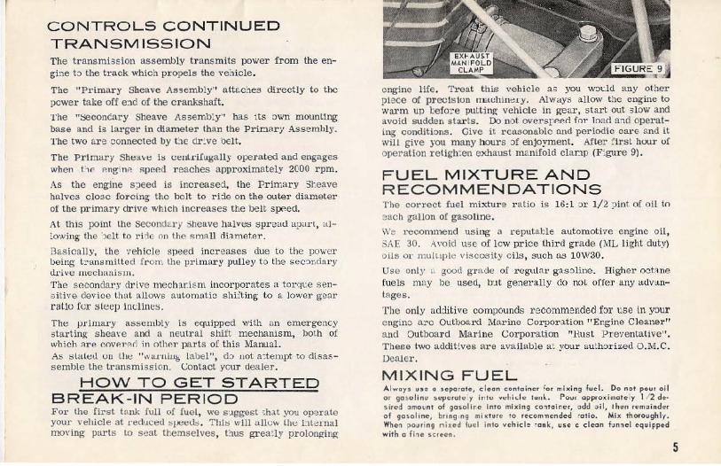
engine life. Treat this vehicle as you wo~:.ld any other place of precision rnachim:a ·y. Always allow the engine to warm up befo:re putting vehicle in gear, start out slow and avoid sudden s tarts. Do not overspP.P.rl for load a:1d operating c onditions. Give it reasonable and periodic care and it will give you many hours :>f enjoyment. After :'1rst hou1· of operation r e tigh:en exhaust m~nifold clanp (F:gure 9) .
FUEL MIXTURE AND RECOMMENDATIONS T he co rre ct fuel mu:ture ratio is 16 :1 ::lr 1/2 pint of oil to each gallon of gasoline. We r ecomme nd using a repulal::le automotiYe engine oil, SAE 30. Avoid use of low price third grade (ML light duty) o ils o r m u iLtplt• vis cos ity oils, such u.s 10W30.
Use only a good grnde of regt\lar gasoline. Higher octAne fuels may lle used, b·Jt generally do not offer any advantHges.
The only additive compounds recommended for use in your e ngine o.rc Outboard Marine Corporation "Engine Cleaner" and Outboard Mariue c.;orporation "Rust Preventative". These two additives are available a: your authorized O.M.C. Dealer.
MIXING FUEL Alwoys u"e o separate, c lcon c:on1oincr for mixi ng fuel. Do nr>t pour oil or go solinll :.vpurutu y in lu vt:l1ide tunl. Pour approxin1otely 1/ 2 des ired ~mount of gasalir.e Into mixing conta iner, add oil, then remoinder of goso l tne, bro ng ng mi ~ture to recom11ended ·otio. Mix thoroughly. Whe1 po uring nixed lucl into vehicle ·ank, use c clean fuMel equipped with o fh c sc reen.
5
STARTING ENGINE (Refer to Fig1lres 6 and 7)
MANUAL STARTI~G MODELS 1560 ·AND 2060
1. Fill tank with corroct fuol miJ<turo (..,o pogo 5).
2. Pull "Neutral-Shift" knob out to neu':ral position and Set Parking Brake in "lock" position.
;j , Move carburetor "Warm~up Lever" in direction of arrow, to warm-up position.
4. Turn ignition key to "ON". 5. Push primer rod three or four times . If engine does
not start immediately, prime once more. The number of times will depend upon the operator becoming familiar with s tarting a cold or warm engine. Do not ove.r ?rime. Priming deliYers solid fuel to the cra:'lkcase bypassing the carburetor.
6. While holding throttle lever partially open, grasp starter handle firmly and pull slowly until starter engages, then pull tu ::;tart. After engine i::; wa.s:·m, move "Warmup Lever" in opposite direction of arrow to operating position. CAU'T'lON: Do not over speed engine when vehicle is stationary and shift knob i; pulled out in neutral posttlon.
7. After engine has warmed up, push "Neutral-Shift" knob in to running position and. release Pllrkjng Bl'ake. Pressittg thro~tle leYer will :;>Ut vehicle in motion. Releasing the throttle lever wlll bring engine back to idle.
8. To stop vehicle, squeeze brake level'. Put in "Lock" positioil when vehicle is not in use.
9. To stop engine, turn ignition switch to "OFF" position. 10. For warm starts, it is not usu>~.lly nP.cP.ss!lry to prime
or use the Warm-up Lever.
ELECTRIC STARTING MODEL 2065
1. Fill tank with corroct fuol mixfure (see poge 5).
2. Pull "Neutral-Shift" !mob ot:t to net:tral pos1tlo:1 anll Set Parking Br ake in " iock" position.
3. MoYe carbur etor "Wa1·m-up Lever" in direction of arrow, to warm-up pos1tion.
4. Turn ignition ~ey to "ON". 5. Push primer rod thrae or four times. If engine does
not start immediately, prime once more. The number o!' tines will depend upon the operator becoming familiar with ;:;tarting a cold or warm engine. Do not over prime. Priming delivers solid fuel to the crankcase b)-passing the carburetor.
6. While holding throttle 1e·1er partially open turn key to "S'T' ART'' position. As soon as engine starts release key. If engine fails to start, don't hold key start switch on for over 10 seconds. Momentarily release and Lhtm Lry agair:. After engine is wru·m, move "Warm-up Le·;er" in opposite direction of arrow to operating position. CAUTION; Do not over s peed engine when vehicle is s cationary and shift knob is out or in neutral position.
7. After engine has w!lrmed up, push "Neutra l-Shift" knob in to running position and release Parldng Brake. Pressing throttle lever wlll put vetlcle ln mmlon. Releasing the throttle lever will bring engine back to idle.
8. To stop vehicle, squeeze bralte lever. Put in "lock" position w:ten vehicle is not in use.
9. To stop engine, turn ignition switch to "OFF" position. 10 . For wa.rm -starts, it is not usuRlly nRcessary to prime
or usc the Wa.rm-up Lever.
6
r EMERGENCY STARTING
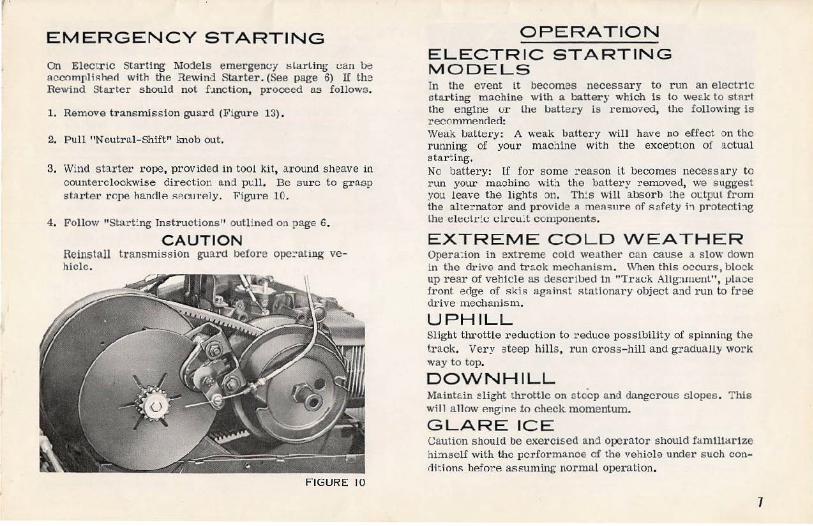
on Electr ic Starting Mojels emergem;y ~larLing uan be ac cnmpl i!':hP.cl with the Rewind Starter. (See page 6) If the Rewind Starter should not f:mction, proceed as follows.
1. Remove transmission guard (Figure 13) .
2. Pull "Neutra.l-Shift" knob out.
3. Wind starter rope, provided in tool kit, around sheave in counterclockwise direc t ion a.nd pdl. Be sure to grnsp sta.rt.e r rope hanrlle !'<er.~n·P.ly. Figure 10.
4 . Follow "Start~ng Instructions" outlined on page 6.
CAUTION Reins tall transmission guard befor e ope:::at ing ve-hiclc.
F IGURE 10
OPERATION ELECTRIC STARTING MODELS In the e·1ent it becomes necessary to run an electric starting machine with a battery which is to weE.k to stAr t the engine or lhe batte1·y ls removed, the following is recnmmenried: Weak batte1·y: A weak battery will have no effect on the running of your machine with the exception of actual starting. No battery: If for some reason it becomes necessary to run your machine wit~ the battery r emoved, we suggest you leave the lights on. Th~s will absorb the ot:.tput :from the alternat·::Jr and provide n mea;;ure of safP.ty ;, protecti:lg the elel:l.J:ic Cil'cu:t components.
EXTREME COLD WEATHER Opera: ion in extreme cold weather can cause a slow down in the drive and track mechanism. When this occurs, block up rear of vehicle as descrtl.>ed in "Tral:k Alig:uw::nL", J:.llace front edge of s kis agA in!':t stationary object and run to free drive mechanism.
UPHILL Slight throttle reduction to r educe possibility of spinning the track. Very .steep hills, run cross-hill and gradually work way to top.
DOWNHILL Mainte.in slight throttle on steep and dangerous slopes . This will a llow P.nginP. fo check momentum.
GLARE ICE c aution should be exercised and ope1'ator should fam111arlze hi:nself with the pcrformnnoe of the vehicle under such conrlitions hefore assuming normal operation.
7
SAFETY PRECAUTIONS 1. uo not attempt to perform repairs on your vehi<.:le while
engine is running.
2. Al ways disconnect spark plug wire's before servicing any part of Lhe engine or· drive unrt .
3. Never use your 'Jehicle withnut thP. l'f!Wind starter or the chain and transmission guard properly secured in plaue.
4. Be certain no one is behind unit. when m2.king A. f.Asf: start, as ice, stones, etc., may be thrown into the air by the lugs on tho:: Lr·acl~.
5. Always 'J!"e two hands for steering.
6. Keep feet on running bourdz at a ll times.
7. Neutral-Shift knob out and .Parking Brake on whenever vehicl·:') is not in us c.
GENERAL MAINTENANCE
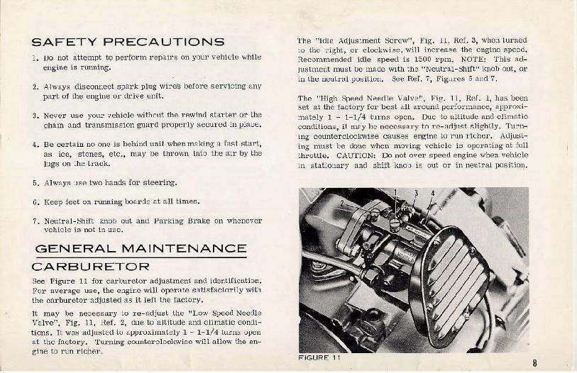
CARBURETOR See Figur e 11 for carburetor adjustment and ider.tification. For average use, the engir.e will operate satisf:wtorily wif1 the carburetor a:ljusted as it left the factor.y.
Jt may be necessary to re-adjust the "Low Speed Needle Valve", Fig. 11, Hef. 2, due to altitude and climatic conditions. n wa!:> auj u!:>Led to approximately 1- 1-1/4 tur ns open ttt t he fl),ctory. Turning countcrolock.vioc will allow the engine to run richer.
The "ldle Adj uscment Screw", Fig. 11, Ref. 3, when turned to the right, or clockwise , will i ncre(tse the engine s peed. ~ecornmended idle speed is 1500 rpm. NOTE: This adjustment must be made with ~he "Neutral-Shift" l<nob out, or in Lhe neulral posit ion. See Ref. 7, Figures 6 and 7.
The "High Speed Nee.clle Valve", Fig. 11, Ref. 1, has bee n set at the factory for best all around performance, approxi:nately 1 - 1-1/4 turns open. Due to a ltitude and climatic conditions, it may be necessary to re-acljuf;t slightly. Tu!'ning counterclocl~'l'ise causes engine to run richer. Adjusling must be done when moving vehicle is operating at full throttle. CAUTION: Do not over speed engine when vehicle in stat:onary and s hift kno:J is out or in neutral posit ion.
FIGURE 11 8

GENERAL MAINTENANCE CONTINUED ENGINE SHROUD- REMOVAL 1. Release latches. 4. D!sconnect wiri:1g (Fig.1re :2) . 2. Remove knurl ell knoi.J . 5. Shroud can new be t<tl<en off unit. 3. Remove gas cap and ring cover. 6.
BATTERY CAUTION : Before disconnectmg <.ny electrical components, di:;con,P.r.t fhP. hMJery cables th·.1s r em:>ving th:} battery from the e:ectrical circuit. When reecnneetir.g ua~tery cables, observe polarity, red cable to positive (-t-) batt::ry terminal an:1 ·)l:lCk cal:le to negatiq~ (-i battery terminal. Reverse ?o:arity will Llarnage the recttner assembly which provides the necessary current to charge the battery.
CHAIN & TRANSMISSION GUARD Metal guards s hield the belt and trans miss ion chain. For chai:l inspection or servicing, remove left foot res t, then screws which hold ~m·cl in place.
GAS TANK To drai n gRR t:1nk for !'>Al 'V iCP. m· off-seJ•son storage 1·e move dro.in plug in fuel line fitting. Be ce:-tain to check for leal<age when refilling gas tank.
DRIVE CHAIN ADJUSTMENT Total s lack must be 1/2", Fig·ure 14. L L ·::lOsen ::ldj' IS' ing sCl'eW lnck nnl. (Fig. 15, Ref. 1) . 2. To tighten cha in, move screw elockwis~ (Ref. 2). 3. T o loosen chain, move screw counterclockwise. 4 . R.?-- tiehtP.n nut (RF:f. 1) .
NOTE: If .t is imposGil:lc to ret:J.in r.djuoting screw in its original :·10:e, remove It and Insert in second hole which has appeared in the sl:>t. Consul t your Dealer when fur ther adjustment is necessary. FIGURE 14
9
GENERAL M A INTENAN CE CONTINUED
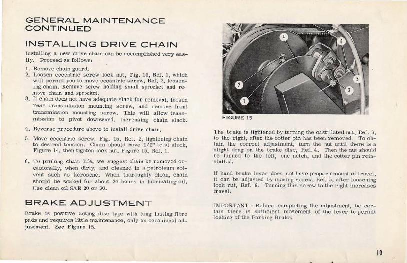
INSTALLING DRIVE C HAIN Installing a new drive chain can be accomplished very easily. Procee:l as follows:
1. Remove chain guc.rd. 2. L oosen eccentric screw lock nut, Fig. 15, Ref. 1, which
will permit you to move eooentric screw, Ref . 2, loosening chain. Remove screw hol:ling small spruck~L and re· move chain and sprocket.
3. If chain does not have adequate slack for removal, loosen rea!" lransmisslun mounting screw, aml n:move I1uul trancmicsion mounting screw. This will allow transmission to p ivot dovmwRrd, increasing cba.in s l ack.
4. Reve1·se procedure aoove to ins tall drive chain.
5. MoYe eccent.ric screw, l<'ig. 15, Ref. 2. tig11tening chain to desired tension. Chain should have 1/2" total slack, Figure 14, then tighten lock nu: , Figure 15, Ref. 1.
6. To prulon~ chail: life , we suggest chain be l' Cmovcd ooc acionally, when dirty, and cleaned in A petJ'olP.um solvent such as kerosene. When tnoroughly cl ean, chain sho:tld be soakeu for about 24 hours in lubricating oil. Use clean oil SAE 20 or 30.
B R A K E A D J USTMENT Brake 1s positive acting disc ly!Jt:: with !ong- lasting flb1·e pads and requires little maintenance, only an occasional adjustment. See FiffllrA 1 fi.
F IGURE 15
The br ake is tightened l)y turning the cast lllatt:tl nul, Ref. 3, to the right, ::.fter the cotter ?i:l has been r emoved. To ohlain the corr ect ajjustment, turn the nut ur.tll ~here i:s a alight drag o n the brake disc, Ref. 4 . Then the nut shoulrl be turned to the left, one nc.:L<..:h, e:-.nu Lhe cotter pin r eins talled.
If hand brake l ever does r.ot have proper 11mnunt of travel, It can be adjus~ed I.Jy moving screw, Ref. 3, aiter loosening lock nut, Ref. 6. 'I\trning this screw to the right incre~:.ses traveL
:MPORTANT - Before completing the adjustment, he r.P.r tain t:J.ere IS sufficient moYemenl of the lt:v~:a· to .~:-ermit locking of tr.e P a rking Brake.
10
GENERAL MAINTENANCE
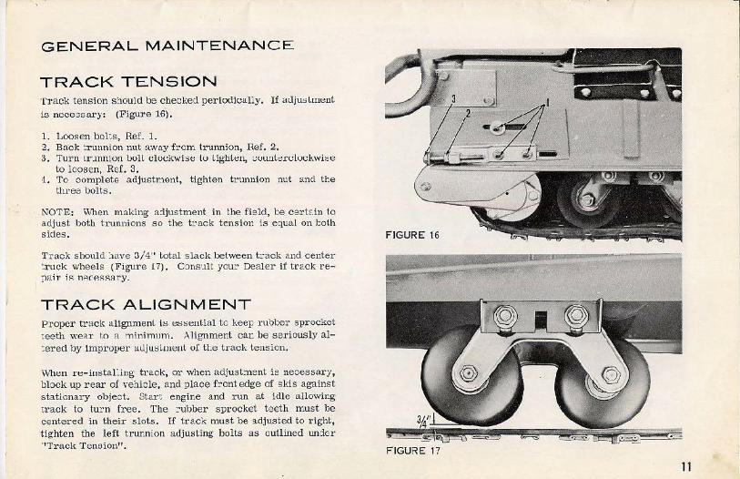
TRACK TENSION Track tension should be chec~:ed periodically. If atljlli>lmenl is necessary: (Figu1•e lS).
1. Loosen boLs, Ref. 1. 2. Back trunnion nut away from trunnion, Ref. 2. 3. Turn ~r.mnton boll clockwise lo lighlen, t;uunl~::rt!lockwi~e
to loosen, Ref. 3. -1. To complete adjustment, tighten trunnion nut and the
three bolts.
NOTE: \Vhen making a:ljustment in the field, be cert~.in to adjust both trunnions so the track tension is equal on J:olh sictes.
Track should :1ave 3/4" total s lack between t rack and center truck wheels (Figure 17). Consult your Dealer if track re
I pai:r iR nRCP.SS::Jry.
TRACK ALIGNMENT Pr oper tracl< aUgnmenL ls essential to keep rubber sprocket teeth we:~r to :1 minimum . Alignment can be se1·iously altered by Improper atljusl ment o! the track tension.
\lv'hen r·e-instaLiug track, or when adjustment is necessary, block up r ear of ve~icle, and place front edge of skis against stationary obje·:::t. Start engine and run at idle allowing track to tu:::n free. The r ubber sprocket teeth must be centered in their slots. If track must be !ldjusted to right, tighten the left trunnion adjusting bolts as outlined tmder ''Track Tension". FIGURE 17
11
GENERAL MAINTENANCE CONTINUED
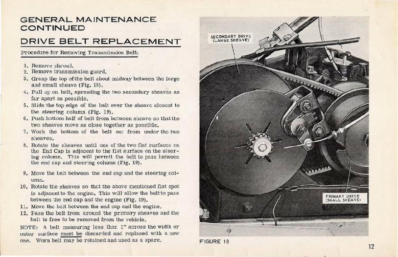
DRIVE BELT REPLAC EMENT Procedure for Removing Tram;mls:sion Belt;
l. Removt:: olu·oud. 2. Remove transmission guard. 3. Grasp the top oftl:e belt about midway between the large
and small sheave (Fig. 18) . ~ . Pull up on belt, spreading the two secondary sheaves as
far apart as possible. li. Slide the top edge of the belt over the sheave closest to
the steering column (Fig. 19). G. Push bottom hal£ of belt from be:wccn sncavc so that the
two sheaves move as close together as po3sible. 7. Work the bottom of the belt ou~ from under the nvo
s:teaves. 8. Rotate the sheaves until one of the two flat surfaces on
the End Cap is adjacent to the flat surface on the steering column. T hi.s will J:lflr.mit the belt to pa3s between the end cap and steering column (Fig, 19).
9. Move the belt between the end cap and the ste~ring col-umn.
10. Rotate the sheaves so ttlG.t the above nentloned flat spot is adjacent to the engine. This will allow the belt to pass between :he end cap and the engine (Fig. 19).
11. Move the belt between the end cap and the engine. 12. Pass the belt from around the primary s heaves and the
belt is free to be removed from the vehicle . NOTE: A belt measuring less thar. 1" across the width or oul~.1· surface must be discarded and rcpboed w:th a. !\ew one. Worn belt may be retained and used as a spare. F IGURE 18
12
GENERAL MAINTENANCE CONTINUED
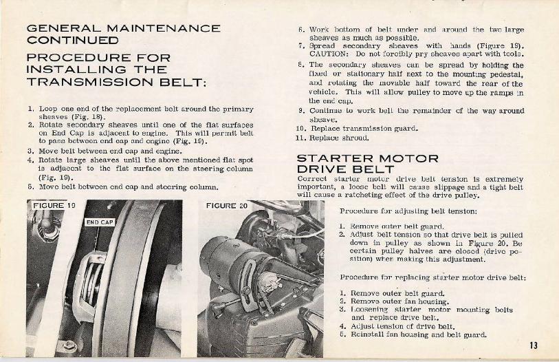
PROCEDURE FOR INSTALLING THE TRANSMISSION BELT:
1. Loop one end of the replo.cement belt around the prima.ry sheaves (Fig. 18).
2. Rotate secondary sheaves until one of the flat surfaces on End Cap is adjacent to engine. This will JJermiL belL to pass bet\veen end cap and engine (Fig. 19).
3. Move belt between end cap and engine. 4. notate large shea-ves until the above mentioned flat spot
is a.dja.ecnt to the flat surface on the steering column (Fig. 19).
5, Move belt between end cap and steering column.
6. Work bottom of belt under and around the two large sheaves as much as possible.
7. Spread secondary sheaves with :tands (Figu1·e 19). CAUTION: Do not forcibly pry sheaves apart with tools.
6. The secoudar·.v sheaves can be spread by holding the fixed or stationary half next to the mounting pedestal, an<.l L'oLa ling the movable half toward the rear of the vehicle. Thi::; will allow pulley to move up the 1·amps in the enc cap.
9. Continue lo work bell the remalndel' of the way around sheave.
10. Replace transmission guard. 11. ReplGt.t:e shroud.
STARTER MOTOR DRIVE BELT Correct sta.L·te.r motor drive IJ~H tension is extremely imp01·t:mt, o. loose belt will cause s lippage and a tight belt will cause a ratcheting effect of the drive pulley.
PL·oueuure fur Gt.ujusling bell tension:
1. RP.movP. ont.e't' belt guard. 2. Ad.1ust belt tension so that drive belt is pulled
down in pulley as shown ln Figur·e 20. Be cert:.in pulley halves are closed (drive posit ion) wten making this adjustment.
Procedurf\ fol' l'P.placing sta'i-ter motor drive belt: . .
1. Remove outer belt guard. 2. Remove outer fan housing. ::L r ,oosP.ning starter motor mounting bolts
and replace drive belt. 4. A<.l.iu~l lensiun of drive belt. 6. Reinstall fan housing and belt guard.
13

SKI ALIGNMENT Ski alignmAnt is necessu·y when the skis are not parallel with each other aml lh~:: vt:hlcle body when the har.dle bar is in the normal stroight- driving position.
To align skis, proceed as follows:
1. "Place handle bar in the no::-mal :;traight-driving pos:tion.
2. Remove shroud. 3. RemovP. nut and washer from
steering arm, Figure 21, Ref. 1. 4. Loosen locki:lg nut, as illus-
trated in F igure 21, Ref. 2. F IGURE 21 5. Turn ball joint clockWise to toe ski out -- t.;Owlterclock
wise to toe ;;ki in. 6. Reassenllle when s kls art: vantllel w:th each other and
vehicle body.
OFF SEASON STORAGE 1. Dlock vel'.iclc off ground to tal~e weight off track and
skis. 2. Drain gas tank. 3. Remove carburetor 1:1tal{e filter screen. 4. Run engine with "warm-up" lever set at point of arrow
and inj~t OI'IIC Rust Preventative Oil (\'lith oil can) rapidly into carburetor until engine stops .
5. Turn off ignition and replace filter screen. 6. Luu:st:Jl track te nsion. 7. Rub bottom of ski a:1d other unprotected surfaces of 'JP.-
hicle with oily cloth. 8. store in dry, well-Yentilnted nren.
AFTER STORINGBEFORE US ING 1. Adjust tra~k for proper tension.
2. LuiJricate:: all points a::; :specified under "Lubrication", 3. Tighten all screws and nuts. 4. Th0rou~h'1Y clean any surfaces th~t need refinishing, and
touch-ul~; Obtain paint from your Dealer.
TROUBLE CHECK LIST Do not immeCiatel y assume you have mechanical ctfflcuttles beiore you ••.
CHECK FUEL SYSTEM FOR .......... .
CHECK IGNITION SYSTEM
Fuel in tank Propel' fuel miXture Fuel flow to carburetor Propt:r carwrewr adjuslmt:nl
Loose spn::k plug lend T oose spark plug (poor compression) Incorrect spark plug gap Spark plug c arboned or
FOR .. .... . . • •• bu:rned
CHECK DRIVE BELT & DRIVE CHAIN FOR ........... .
CHECK TRACK FOR ....... .
Worn belt -- loss of normal speed Drokcn belt Improper r.hain tension Dry chain Broken chain
Improper lension Alignment Broken cleat Loo:;e cleat Missing r ivets Damaged belt
14

TROUBLE
Engine fails to sta1·t.
Rewind starter fails to engage. Engine run::; rough.
EngLne won'~ idle.
Low RPM.
SERVICE DIAGNOS IS
PROBABLE CAUSE
Fuel tank empty. Ignition switch off. Engine starving for fuel. Plugged fuel line or filter. Engine floods. lm!)ruper o r no ignition.
Broken or worn parts internally. Carburetor OUt Of adjustment. Poor ignition.
Idle speed set too low. Carburetor out of adjustment. Poor ignition.
Carburetor air filter dirty
Fill with conect fuel mi..A'ture. Turn on or check for short.
RF.MF.DY
Prime and check carburetor a~ustment. Check for position of warm-up lever. Clean fuel lines and filter.
Check carburetor adjustment, and position of warm-up lever. Check spark. plug lead::; lo ~ :sure lbt!y !lie securely In place. Check for correct spark plug with the recommended gap and in good condition. With spark plug removed, attach high tension lead. and place metal seat of plug against engine . Pull starter. If spark appears across electrodes spark plug and magneto arc in good condition. If no spark appear·s, plac.;e a :small metal object into the end of the high tension lead, and hold the end about 1/8" away from a clean metal surface. Pull starter. If spark appears, r eplace spark plug. If no spark appears, trouble is lo~a.t.eci somewhere i n the intArnB.l mRgneto. Consul t your dealer. Repeat procedure for second cylinder. CAUTION; When checking for spark , grasp the h igh tension leau at least 1'' !Jack ft·om t~::rminal to avoid shock. If engine falls to start after the above checks have been made, consult your dealer. Consult your dealer. Follow procedure outlined for emergency s tarting.
Adjust carburetor,
Follow same check procedure as for "improper or no ignition" under "engine fails to start".
Increase idle speed setting to approximately_ 1500 R~M. Adjust carburetor.
Follow same check procedu:t;'e as for "improper or no ignition'' under •tengine fails to start". Remove and wash in clean gasoline, sha:-~:e dry - DO NOT oil.
15
'T'ROUBLE
Low RPM. (cont. )
Vehicle fails to move when throttle i s dopressed.
Low vehicle speed.
SERVICE D IAGNOSIS CONTINUED
PROBABLE CAUSE
Carburetor ouL uf adj us tment. Excessive engine WP.ar.
Neutral shift ln neutral position. Drive belt worn or broken. Drive chain o ut of adju~'>tment or broken.
Drive b elt worn. Skis out of olignment. 'fight track.
REME DY
Adjust carburetor.
Consult your dealer.
Pu::;h Jlt::Ul!al shift knob into drive posit ion, .f'igure 22. Replace drive bP.lt.
Adjust or replace drive chain.
Replace drive belt. Align skis.
Lights won't light.
T.oose connections. Bo.d switch.
Adjusl t rack tension. Check and tighten. Check or replacP.. F IGURE 22
Bulb burned out .
No apparent output from alternator.
MAINTENANCE
TIME
After 1st 3 hrs.
MAINTENANCE
Adjust Chain Tension (Auju::;t e::ve 1·y 25 hrs. or as require d) Adjust Track Tension Check 'T' rack Alignment
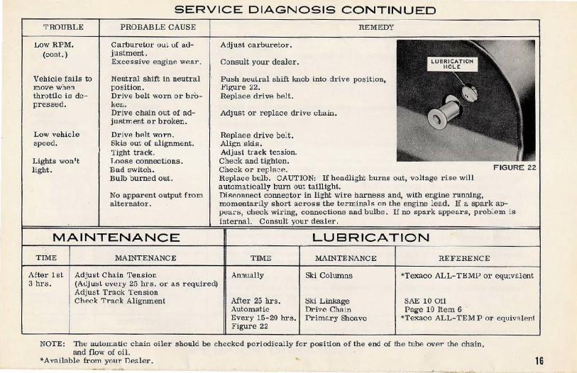
R eplace bulb. CAUTION: If headlight burns out, voltage rise will automatically burn out taillight. DiRconnect connector in light wire harness and, with engine running, momentarily shor t across the ter minals on the engine le ad. If a spark appeat·s, check wiring, connections and bulbs . If no spark appears, prob: em is internal. Consult your dealer.
TIME
Annually
After 25 hrs. Automatic Every 15-20 hrs . Figure 22
LUBRICATION
MAINTENANCE
Ski Columns
Ski Linkage Drive ChR in Prirn.tl.ry Shca.vc
REFERENCE
*Texaco ALL-TEMP or equivalent
SAE 10 011 Page 10 Item 6 ·
*Texaco ALL-TEMP or equivalent
NOTE: The auton:a tic chain oiler should be checked pe r iodically for position of the end of the t ube ovP.r the chain, and flow of oil.
*Available from your Dealer. 16
f
ITEMS OF SPECIAL
INTEREST
REPAIR SERVICE De:~.lers usually carry a complete stock of spare parts. If you need parts, or repair service, consult your dealer, whose name and address can be found in the yellow pages of yo\U· tdt::vhout:: illt·t::clury umlt::r· "OuUJuanl Muwrs".
REPLACEMENT PARTS Be sure that only factot·y approved parts designed for your vehicle are used as r eplacements. Your OMC dealer can be relied on aR 11. source o£ genuine OMC parts. Replacement parts not of ou• manufacture h.av~:: not been approved for use on Snow Cruisers.
Your warranty will be void &; to failures traced to the use of parts not manufactured by OMC .
OWNER ' S WARRANTY CERTIFICATE In order to affo1·d nationwide service to all customeL·s, a:1 "Owner' s Warranty Certificate" is a ttached to the vehicle. THlS CERTIFICATE MUST BE FILLED OUT COMPLETELY BY THE DEALER A:'fD CUSTOMER AT THE
TIME THE SALE IS COMPLETED. The owner may present this certifioa:c to a Johnnon dealer when making claim for wru-ran:y.
•J
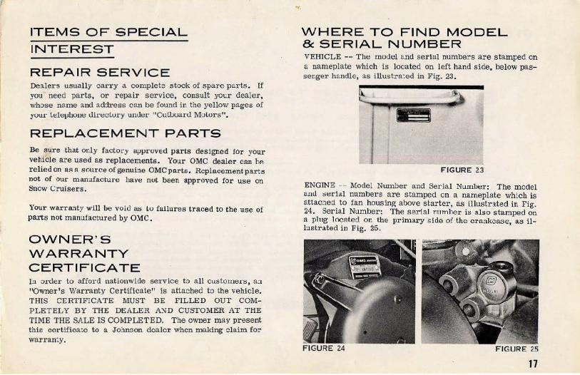
WHERE TO FIND MODEL & SERIAL NUMBER VEHICLE -- Tht:: model and serial numbers are stamped on a nameplate which is located on left hand side, below passenger handle, as illustra:ed in Fig. 23.
FIGURE 23
ENG1NE -- Model Number and Serjal Num!J~::r : The model and t~t::rii:tl numbers are stamped on a nameplate which is attached to fan housing above starter, as illustrated in Fig. 24. Serial Number: The serial numher is also stamped on a plug l ocat.ed on the primary side of the c r ankcMe, as illustrated in Fig. 25.
17
~WARRANTY~ We warrant, to the ·original purchaser, each new snow vehicle of our manufacture to be free from defects In matl:lrho.l and workmanship under normal use and service, our obligation under this warranty being limited to :naking good at the factory any part or parts thereof which stall, within 90 days from date of first use, be returned to us with be transportation· charges prepaid, and which our examir.at:on shall disclose to our satisfaction to :1ave been thus ciefective; this warran:y being expressly in lieu of all other warranties and representations expressed or implied and of n· l other liabili:ies in connection with the sal e or use of any vehicles .
This warranty shall not <~pply to !l.ny vehicle which shall have been repaired or altered outsida the factor y in any way so as to affect its st:abili:y, nor which has been subject to misuse, ne?:ligence or accident, o::- operated in any other way than in acc:>rdance with ou- operating and maintenance instructions . Nor does the warranty extend to repairs made necessary by the li.S e of infRrior parts or accessories . or by the use of types of accessories not recommended by Outboard Marine Corporation of Cana cia Ltd .. nor does it apply to normal wear and tear.
We make no wo.rrnnty in respect Lo trada accessories not of our ml'lnufa.cture. inasmuch as they are usually warranted ocparately by their respective manufacturers .
To make a claim under t'li:; wo.rrnnty, contact the a uthori zed Dealer frcm whom your vehicle was originally purchased or the nearest authorized Dculcr. Vehicles or parts t hereof s hi?ped to 1"11 P. fllctor y for our inspection mu:;L situ" n1odel and serial numbers, and must be shipped transportation c ha rges prepaid.
T!-US WARR'\NTY APPLII:S TO ALL SNOW CR:JISER SNOWMOBILES SCLD IN CANADA.
SNOW CP.UISERS SOLD ELSEWIIEH.E , EXCLUDING THE UNITED STATES OF AMERICA, ARE WA~RANTF.n 3Y EITiiER OUTBOARD MARINE INTERNATIONAL S . A . NASSAU, BAHAMAS OR. OUTBOARD MARINE Bl!:LGIUM $ . A . , BRUGES BELGIUM .
18