hammer knife flail mower shredder - gearmore · operation page 2 the gcf-3w shredderscan be used in...
TRANSCRIPT

HAMMER KNIFEFLAIL MOWER
SHREDDER
Operation & ServiceManual For Models:
GCF61-3W, GCF69-3W &GCF79-3W
May 2007FORM: GCF-3WMwrs.QXD

Installation . . . . . . . . . . . . . . . . . . . . . . . . . . . . . . . . . . . . . . . . . . . . . . . . . . . .1
Operation . . . . . . . . . . . . . . . . . . . . . . . . . . . . . . . . . . . . . . . . . . . . . . . . . . . . .2
Safety Information . . . . . . . . . . . . . . . . . . . . . . . . . . . . . . . . . . . . . . . . . . . . . .3
Lubrication . . . . . . . . . . . . . . . . . . . . . . . . . . . . . . . . . . . . . . . . . . . . . . . . . . . .4
Pre-Operation Check . . . . . . . . . . . . . . . . . . . . . . . . . . . . . . . . . . . . . . . . . . . .5
Mower Adjustments . . . . . . . . . . . . . . . . . . . . . . . . . . . . . . . . . . . . . . . . . .6 - 7
Roller Height Control . . . . . . . . . . . . . . . . . . . . . . . . . . . . . . . . . . . . . . . . . . .8
Drive Belt Tension Adjustment . . . . . . . . . . . . . . . . . . . . . . . . . . . . . . . . . . .9
Troubleshooting . . . . . . . . . . . . . . . . . . . . . . . . . . . . . . . . . . . . . . . . . . . . . . .10
Safety Precautions . . . . . . . . . . . . . . . . . . . . . . . . . . . . . . . . . . . . . . . . . . . . .11
3-Point Hitch Parts . . . . . . . . . . . . . . . . . . . . . . . . . . . . . . . . . . . . . . . . . .12-14
Frame Parts . . . . . . . . . . . . . . . . . . . . . . . . . . . . . . . . . . . . . . . . . . . . . . . .15-17
Transmission Parts . . . . . . . . . . . . . . . . . . . . . . . . . . . . . . . . . . . . . . . . . .18-19
Gearbox . . . . . . . . . . . . . . . . . . . . . . . . . . . . . . . . . . . . . . . . . . . . . . . . . . . . .20
Limited Warranty . . . . . . . . . . . . . . . . . . . . . . . . . . . . . . . . . . . . . . . . . . . . . .21
TABLE OF CONTENTS
Date of Purchase:__________________________
Model Number:____________________________
Serial Number:____________________________

INSTALLATION
Page 1
BEFORE ATTACHING THE MOWER TO THE TRACTOR
1. Make sure that the mower is suitable for your tractor's horsepower.
YOUR TRACTOR'sMODELS MAX. H.P.
All 75
CAUTION: Please note that if these limits are exceeded, it will invalidate your warranty.
2. Make sure the lower links and top link on the 3-point hitch arms of your tractor are the correct size (Cat. II), so that they correspond to the size of the hitch on the mower you have purchased.
3. P.T.O. Installation:
First, connect the P.T.O. shaft to the tractor. With the shaft in its shortest position,there should be about a 2" clearance between the end of the gearbox shaft and the end of the P.T.O. shaft. Should it be necessary to shorten the P.T.O. shaft, shorten both male and female shafts equally, keeping the protective tube covers 1" shorter than the steel tubes.
Particular attention should be given to carefully removing all burrs and to clean and lubricate the steel tubes and protective covers. There must be sufficient telescopic movement so that the two tubes do not touch the end of the P.T.O. shaft.
It is mot important to carefully raise and lower the mower with the tractor hydraulic system, making sure that the P.T.O. shaft does not bottom or disengage the telescopic shaft tubes, otherwise damage may occur.

OPERATION
Page 2
The GCF-3W Shredders can be used in a center, offset or tilt position.
Before starting work, check that the embankment is solid. If the land is unstable, the tractorcould roll over, as the weight of the machine is offset to the side.
Having checked the bank for stability, slowly place the head on the ground and set it in the float-ing position on the tractor distributor. It will then float, following the contour of the land. Thenlock off the float position to preserve the machine angle, raise it 4" off the ground, engage thepower takeoff and then set the head down on the ground again. At this point re-engage the float-ing position so that the machine can float while working.
Before starting any work, check the ground for any foreign bodies not involved in the agriculturalwork; for example, pieces of steel or glass, nylon, steel wires or cables, polluting powders or liq-uids such as; pesticides or poisons, explosives, flammable substances, etc.
Make certain that no one is loitering within the area and if necessary, send them away beforemoving the machine.
HYDRAULIC SIDESHIFT
The GCF-3W Shredder is fitted with hydraulic side shift therefore, a second double actingexternal connection is needed on the tractor. With hydraulic side shift fitted, it is possible to sideshift the machine to any position within the working range while it is on the move. It is advisableto color code the hoses on the machine and the tractor distributor, so that you can always con-nect them quickly and correctly. this ensures that the oil will always circulate in the right direction.
ALIGNING SHREDDER
Lower the machine and note if the full width of the roller reaches the ground at the same time.If it does not, adjust the level box on the drop links of the tractor until it does.
Never load the roller with anything but the weight of the machine.
Never turn corners with the roller on the ground. Before turning, lift the unit off the groundslightly.

SAFETY INFORMATION
Page 3
OPERATIONAL SAFETY:
Guards and safety shields are for your protection. DO NOT operate equipment unless they are in place.
Always operate tractor PTO (power-take-off) at recommended RPM (revolutions per minute).
Disengage tractor PTO and shift into neutral before attempting to start engine.
Read and observe all safety decals on the tractor and mower.
NEVER allow anyone within 25' of machine while it is in operation.
DO NOT stop or start suddenly when going uphill or downhill. Avoid operation on steep slopes.
Be alert for holes in terrain and other hidden hazards. Always drive slowly over rough ground.
Reduce speed on slopes and in sharp turns to prevent tipping or loss of control. Be careful when changing direction on slopes.
Stop mower and tractor immediately upon striking an obstruction. Turn off engine, inspect mower and repair any damage before resuming operation.
Disengage power to mower and stop engine before dismounting from tractor, before making any repairs or adjustments, transporting or unclogging mower.
Take all possible precautions when leaving tractor unattended: Disengage PTO, lower mower,shift into neutral, set parking brake, stop engine and remove key from ignition.
Front tractor weights or front tire ballast should be used to enhance front end stability on small tractors.
Check to make sur PTO is properly connected and that the driveline is correct to prevent bottoming out or pulling apart during the full lift range of the hitch.
This implement is designed for a one-man operation. It is the responsibility of the tractor operator to see that no one is in the proximity of the implement when it is started. DO NOToperate the implement with another person within 25' of the implement.
NEVER operate mower with hatch in the wrong working position.
NEVER run mower with rotorshaft out of balance.

Page 4
LUBRICATION
Grease all fittings according to the following schedule:
1. ROLLER - Grease at both ends after 4 hours of operation, until excess grease is visible (Ref. 1).
2. CUTTING SHAFT - Grease at both ends lightly after 8 hours of operation(Ref. 2). DO NOT over grease.
3. P.T.O. SHAFT - Male and female telescopic tubes and universal joints should be cleaned and greased monthly, or more frequently in extreme operating conditions.

PRE-OPERATION CHECK
Page 5
Check tightness of all bolts and nuts.
Check gearbox oil level (Grade SAE80W-90 gear oil).
Grease all points, on all GCF mowers.
P.T.O. (power take-off) speed should not exceed 540 RPM (revolutions per minute).
Check correct length of P.T.O. shaft. When fitted, there should be 3 3/4" free travel on male and female tubing (check in fully raised and fully lowered positions).
The recommended cutting height, with the hammer or blade in its lowest position, is between 2" and 4" (Ref. 1). Basically, the fine height adjustment is achieved with the top link of the 3-point hitch. For a greater height adjustment, it is necessary to raise or lower the roller (Ref. 2).
Drive belt should flex 3/8" (1 cm.) when pushed firmly with the finger.
If your tractor does not have a double clutch, or has a hydraulic P.T.O., an overrunning P.T.O. shaft is required.
Mower should be completely cleaned after use and before storage.

MOWER ADJUSTMENTS
Page 6
FOR VARIOUS TYPES OF MOWING
There is an adjustable rear hatch (Fig. 3) that can be set in one of seven positions to control the amount of power needed to do the work.
1. Adjustment of the rear hatch can be made by removing the two bolts at the side (Fig. 13, ref. 1). Loosen the nut (Fig. 13, ref. 2) until the hatch can be pivoted around bolt (Fig. 13, ref. 3). To fix the hatch in the desired position, align the hole in the side of the casing of the machine with the appro-priate hole in the hatch. Insert the bolt and tighten the self-locking nut (Fig. 13, ref. 1). Tighten the pivot bolt (Fig. 13, ref. 3) with the self-locking nut (Fig. 13, ref. 2).
2. The rear hatch should be in a completely closed position (Fig. 4) when used for mulching of prunings, or pulverizing debris.
3. The hatch is used in position (Fig. 5) to allow the grass clippings to escape above the roller.
4. The hatch should be in a completely open position when the mower is used for grass,cover crop, weed abatement, vegetables, corn stalk and cotton cutting operations (Fig. 6).An open hatch enables the clippings to be discharged quickly, thus allowing a faster mowing speed and lower H.P. requirements.
DANGER: When the hatch is in the fully open position, objects may be thrownout of the machine. Make sure that NO ONE is in the operation area.

MOWER ADJUSTMENTS (Continued)
Page 7
1. Various rolleradjustments3 positions
2. Used for mulchingof prunings
3. Used with rakes tomulch prunings
4. Used for cuttinggrass
5. Used to mulchcornstalk

ROLLER HEIGHT CONTROL
Page 8
The roller can be adjusted for 2 or 3 cutting heights. By raising the roller, you get a shorter cut,by lowering it, a longer cut is achieved. You can also fine adjust the cutting height with the toplink arm. By shortening the link arm, your cut is further from the ground.
A suggested cutting height is having the hammer tips about 2" from the ground.
You can control the power needed and the amount of wear on the hammers by this adjustment.
ADJUSTING REAR ROLLER:
To adjust roller, loosen (Fig. 1, ref. 1). Completely remove (Fig. 1, ref. 2 & 3). Align the appropriate hole in the supportbracket with the hole in the deck to achieve roller positiondesired.
1. There is also an adjustment that can be made on the roller to control mulch size and power needed. By moving the roller toward the cutting shaft (Fig. 7), a finer mulch is produced, requiring less H.P. In this case, we suggest opening the hatch to cut grass,vegetables, cornstalk, cotton, etc.
2. By moving the roller away from the cutting shaft (Fig. 7), a coarser mulch is produced,requiring more H.P. In this case, we suggest closing the hatch to mulch prunings.
3. The third position, or furthest from the cutting shaft, is used only to allow room for rakes on the mower, if needed. Rakes are used when the prunings are laying close to the ground and have to be drawn out.
4. For more precise work and performance, we recommend spending 5 minutes adjusting your mower for the job, this can be done according to the previous recommendations.
5. The roller scraper can be removed when cutting grass, because close positioning of theroller to the cutting shaft permits the hammers to act as a roller cleaning device.
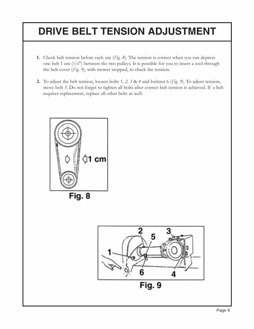
DRIVE BELT TENSION ADJUSTMENT
Page 9
1. Check belt tension before each use (Fig. 8). The tension is correct when you can depress one belt 1 cm (3/8") between the two pulleys. It is possible for you to insert a tool through the belt cover (Fig. 9), with mower stopped, to check the tension.
2. To adjust the belt tension, loosen bolts 1, 2, 3 & 4 and locknut 6 (Fig. 9). To adjust tension,move bolt 5. Do not forget to tighten all bolts after correct belt tension is achieved. If a belt requires replacement, replace all other belts as well.

TROUBLESHOOTING
Page 10
1. Cutting shaft does not rotate properly:
a. Tighten drive belts to correct tension (see page 9).b. Replace belts if they no longer can be adjusted properly.
2. Mower vibrates:
a. Check for loose or missing hammers or bolts.b. Check for hammers that are unevenly worn. If one or more hammers is badly worn,
replace all the hammers the first time. Keep the hammers that are in good shape for future replacement in worn series of hammers. For example: when replacing a worn hammer, replace it with a hammer of similar shape and weight. This will insure a balanced and vibration free cutting.
3. If the cutting shaft becomes jammed, reverse the rotation of the shaft to loosen and release the obstruction.
4. If the hammer mounting ears break off, they must be welded back in their exact position,otherwise the cutting shaft will be unbalanced.
5. If you have any questions or problems, it is always best to contact your dealer immediately.
6. When ordering spare parts, you must contact your authorized Gearmore dealer for original replacement parts. When doing so, please include the following information:
a. Model Numberb. Serial Number

SAFETY PRECAUTIONS
Page 11
1. All adjustments, inspections and repairs must be made with tractor and mower completely stopped.
a. When the mower is in operation, make sure that there is no one near the flying debris from the mower, to prevent the possibility of serious injuries.
b. ALWAYS keep hands and feet away from a mower that is in operation.
c. Check that all guards and safety features are in place and in good operating condition.
2. While mowing, take the necessary precautions to insure operator's and others safety.
3. DO NOT make height adjustment using only the top link. This will cause flying debris to come out the front of the mower and toward the operator. Use the roller adjustment.
We thank you again for your choice of mowers and we remind you that the safety points outlined inthis manual will help you do your work in a safe and efficient manner.

3-POINT HITCH FRAME
Page 12

REF# QTY. PART NO. DESCRIPTION
1 2 96607921 Bolt M10 x 40 UNI 5739 8.8 ZN2 2 97494931 Washer 10.2 x 18.1 x 2.2 ZN3 2 11404031 Fix. Plate Pin4 2 11404039 Bronze Bushing 60 x 70 x 505 2 97036611 Grease Nipple UNI 76636 2 96614721 Bolt M16 x 45 UNI 5739 8.8 ZN7 2 97972521 Lock Nut M16-6S UNI 74748 2 11404024 Revolving Support9 2 97971821 Lock Nut M10-6S UNI 747410 2 13004035 Pin, Short Frame Side11 2 96608321 Bolt M10 x 60 UNI 5737 8.8 ZN12 2 13004037 Nylon Splined Bushing 30 x 38 x 5013 2 11404017 Fix Support f/Variable Displac.14 2 11404004 Joint Arm DX L=90014 2 11404006 Joint Arm DX L=67514 2 11404060 Joint Arm DX L=100015 2 11404003 Joint Arm SX L=90015 2 11404005 Joint Arm SX L=67515 2 11404059 Joint Arm SX L=100016 2 11404013 Support f/Variable Displacement17 2 11404022 3-Point Linkage Cat. 217 1 11404033 3-Point Linkage Cat.117 1 11404086 Attacco A Tre Punti Cat. 117 1 32104044 Linkage 3 for Apple 200218 2 19704013 Cat. 2 Pin 1 & 2 Point Long19 2 16004014 Pin D.1020 2 19704005 Cat. 1 Pin 3 Point + Chain + Pin 1921 2 96610221 Bolt M12 x 45 UNI 5739 8.8 ZN22 2 13004139 Boccola Per P.T.O. Shaft Support23 2 14404021 P.T.O. Shaft Support24 2 97972021 Lock Nut M12-6S UNI 747425 2 96605521 Bolt M8 x 20 UNI 5739 8.8 ZN26 2 97494831 Washer ASA B 27 - 8.2 x 14.8 x 2 ZN27 2 97094911 Smooth Washer UNI 6592 8.4 x 16 x 1.6 ZN28 2 11404043 Pin with Plate D22 x 72 INT=2829 2 11412005 Hyd. Cylinder 60 x 30 x 20029 2 42012047 Hyd. Cylinder 40 x 20 x 160 3/8"30 2 11404041 Pin with Plate D19 x 72 INT=2831 2 97972721 Lock Nut M24-6S UNI 747432 2 96620721 Bolt M24 x 80 UNI 5737 8.8 ZN
3-POINT HITCH FRAME
Page 13

REF# QTY. PART NO. DESCRIPTION
33 2 97973021 Lock Nut M22-6S UNI 747434 2 11404054 CPL Arm DA 25035 2 96629221 Bolt M22 x 150 UNI 5737 8.8 ZN36 2 11404027 Arm 335 x 15 For SMO-AVS37 2 97972821 Lock Nut M20-6S UNI 747438 2 11404065 Spacer 38 x 22 x 8039 2 96618521 Bolt M20 x 160 UNI 5737 8.8 ZN40 2 11412007 Hyd. Cylinder 60 x 30 x 20040 1 42012047 Hyd. Cylinder 40 x 20 x 160 3/8"41 2 17908009 Pin with Plate D19 x 80 INT=4542 2 11404040 Pin F/Joint Support SMWAV-SMLAV43 2 97495034 Washer B-27-12 - 12.2 x 21.2 x 2.5 N44 2 14311010 Pin for Support45 2 13011019 Cap f/Small Support46 2 13011009 Support Foot SMO, SMW/OA, SML47 2 97486611 Bolt 6.3 x 19 UNI 811748 2 97095111 Smooth Washer UNI 6592 10.2 x 21 x 2.0 ZN49 2 97494931 Washer B-27 - 10.2 x 18.1 x 2.2 ZN50 2 96607621 Bolt M10 x 25 UNI 5739 8.8 ZN51 2 48120193 Hose SAE 100R2AT 1/4" x 3000 O-FD52 2 19412002 Hose SAE 100R2ATDN 1/4" x 2200 O/FD
3-POINT HITCH FRAME
Page 14

FRAME
Page 15

REF# QTY. PART NO. DESCRIPTION
1 1 11401006 Cpl Frame SMWAV 951 1 11401007 Cpl Frame SMWAV 1051 1 11401008 Cpl Frame SMWAV 1251 1 11401009 Cpl Frame SMWAV 1551 1 11401010 Cpl Frame SMWAV 1751 1 11401011 Cpl Frame SMWAV 2001 1 11401020 Cpl Frame SMWAV 1352 1 96605721 Bolt M8 x 30 UNI 5739 8.8 ZN3 1 97971721 Lock Nut M8-6S UNI 74744 1 13010033 Side Rubber Protection F.Side5 1 13010034 Blocking Plate Protect Side6 2 96605721 Bolt M8 x 30 UNI 5739 8.8 ZN7 2 11301028 Feather for Upper Side SML8 2 97494834 Washer ASA B - 27 - 8.2 x 14.8 x 2 N10 1 12010002 Belt Protection (H=90_10 1 12010003 Belt Protection SMWA, SML (H 110)11 1 97971721 Lock Nut M8-6S UNI 747412 1 97094921 Smooth Washer M8 9x24x2 ZN13 1 97277980 Oil Seal 9.25x 1.7814 1 96612421 Bolt M14 x 40 UNI 5739 8.8 ZN15 1 97495134 Washer ASA B-27 14.2 x 24.1 x 3 N16 1 97972321 Lock Nut M14-6S UNI 747417 1 97495134 Washer ASA B-27 14.2 x 24.1 x 3N18 1 96612321 Bolt M14 x 35 UNI 5739 8.8 ZN19 1 13008019 Cpl Hatch 17519 1 13008020 Cpl Hatch 20019 1 15008021 Cpl Hatch 09519 1 15008022 Cpl Hatch 10519 1 15008024 Cpl Hatch 12519 1 15008026 Cpl Hatch 15521 1 11010002 Cpl Chain Holder Bar L=9521 1 11010003 Cpl Chain Holder Bar L=10521 1 11010006 Cpl Chain Holder Bar L=15521 1 13010006 Cpl Sh. Stone Guard (L=125)21 1 13010008 Cpl Sh. Stone Guard (L=175)21 1 13010009 Cpl Sh. Stone Guard (L=200)21 1 13010041 Cpl Chain Holder Bar L=12521 1 13010043 Cpl Chain Holder Bar L=17521 1 13010044 Cpl Chain Holder Bar L=20021 1 15010004 Cpl Sh. Stone Guard (L=95)
FRAME
Page 16

REF# QTY. PART NO. DESCRIPTION
21 1 15010005 Cpl Sh. Stone Guard (L=105)21 1 15010008 Cpl Sh. Stone Guard (L=155)22 1 13010038 Stone Guard Model October '9823 1 96610021 Bolt M12 x 35 UNI 5739 8.8 ZN23 1 96612221 Bolt M14 x 30 UNI 5739 8.8 ZN23 1 96612321 Bolt M14 x 35 UNI 5739 8.8 ZN24 1 97495034 Washer ASA B-27 - 12.2 x 21.2 x 2.5 N24 1 97495134 Washer ASA B-27 - 14.2 x 24.1 x 3 N26 1 97972021 Lock Nut M12-6S UNI 747426 1 97972321 Lock Nut M14-6S UNI 747427 1 13010037 Chain Prot. 13 Chains Link 727 1 21010035 Chain Prot. 11 Chains Link 743 1 96964401 Bolt 4.8 x 9.5 UNI 695444 1 97708871 Ext. Galvanized Toothed Washer 5.3 x 1045 1 13010039 Prot. Cover For Greasing Hole46 1 96605621 Bolt M8 x 25 UNI 5739 8.8 ZN47 1 97494831 Washer ASA B-27 - 8.2 x 14.8 x 2 ZN48 1 14008021 Counter Plate F.Rubber (L=125)48 1 14008023 Counter Plate F.Rubber (L=175)48 1 14008024 Counter Plate F.Rubber (L=200)48 1 15008052 Counter Plate F.Rubber (L=95)48 1 15008053 Counter Plate F.Rubber (L=105)48 1 15008053 Counter Plate F.Rubber (L=155)48 1 96605621 Bolt M8 x 25 UNI 5739 8.8 ZN49 1 13008077 Rubber Protection F/Hatch (L=125)49 1 13008079 Rubber Protection F/Hatch (L=175)49 1 13008080 Rubber Protection F/Hatch (L=200)49 1 15008058 Rubber Protection F/Hatch (L=95)49 1 15008059 Rubber Protection F/Hatch (L=105)49 1 15008062 Rubber Protection F/Hatch (L=155)
FRAME
Page 17
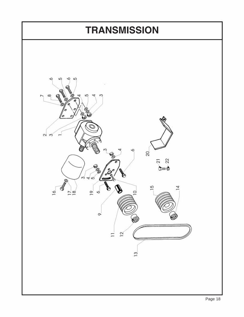
TRANSMISSION
Page 18

REF# QTY. PART NO. DESCRIPTION
1 1 11403006 Gearbox TL311 (9.311.620.00) R=1:31 1 11403007 GEarbox TL311 R=1:1.62 1 11003014 Plate f/Gearbox 6 mm3 1 97972321 Lock Nut -MS UNI 74744 1 97495134 Washer ASA B-27 - 14.2 x 24.1 x 3 N5 1 97093311 Smooth Washer M14 UNI 5714 ZN6 1 96612421 Bolt M14 x 40 UNI 5739 8.8 ZN7 1 97495034 Washer ASA B-27 - 12.2 x 21.2 x 2.5 N8 1 96609821 Bolt M12 x 25 UNI 5739 8.8 ZN9 1 22003062 Splined Bushing f/Taper Lock Seat10 1 97345827 Bolt M12 x 25 UNI 5933 8.8 Black11 1 13003081 Pulley 4 SPB 18011 1 15003055 Pulley 3 SPB 18012 1 13003006 Taper Lock Viblock VK 156 45 x 8012 1 15003054 Taper Lock Viblock VK 156 45 x 80 Std13 1 12003001 Belt BX 4314 1 13003006 Taper Lock Viblock VK 156 45 x 8015 1 15003056 Pulley 3 SPB 14015 1 22003020 Pulley 4 SPB 14016 1 96605321 Bolt M8 x 12 UNI 5739 8.8 ZN17 1 97094921 Smooth Washer M8 9 x 24 x 2 ZN18 1 13010081 Oval Protection 275 x 210 L=21019 1 11403011 Flangia Cpl Attaco Molt.20 1 11410010 Cpl Reinforc.F/Belt Protect.21 1 96610021 Bolt M12 x 35 UNI 5739 8.8 ZN22 1 97038421 Nut M12-6S NI 5588
TRANSMISSION
Page 19

GEARBOX
Page 20

Page 21
LIMITED WARRANTY
The serial number of this product is stored in our computer database, thussubmitting a warranty registration card is not required.
GEARMORE, INC., warrants each new Gearmore product to be free from defects in materi-al and workmanship for a period of twelve (12) months from date of purchase to the originalpurchaser. This warranty shall not apply to implements or parts that have been subject tomisuse, negligence, accident, or that have been altered in any way.
Our obligation shall be limited to repairing or replacement of any part, provided that suchpart is returned within thirty (30) days from date of failure to Gearmore through the dealerfrom whom the purchase was made, transportation charges prepaid.
This warranty shall not be interpreted to render us liable for injury or damages of any kind ornature, direct, consequential or contingent, to person or property. This warranty does notextend to loss of crops, loss because of delay in harvesting or any other expenses, for anyother reasons.
Gearmore in no way warranties engines, tires, or other trade accessories, since these itemsare warranted separately by these respective manufacturers.
Gearmore reserves the right to make improvements in design or changes in specification atany time, without incurring any obligations to owners or units previously sold.
GEARMORE, INC.13477 Benson Ave.
Chino, CA 91710Always refer to and heed machine operating warning decals on machine.