h8508 hydraulic impact wrench - greenlee … · h8508 hydraulic impact wrench greenlee / a textron...
TRANSCRIPT

INSTRUCTION MANUAL
Read and understand all of the instructions andsafety information in this manual before operatingor servicing this tool.
999 1705.0 REV 8 © 2005 Greenlee Textron Inc. 3/05
H8508Hydraulic Impact Wrench
Models 48330 and 48329Serial Code FPB

H8508 Hydraulic Impact Wrench
Greenlee / A Textron Company 2 4455 Boeing Dr. • Rockford, IL 61109-2988 USA • 815-397-7070
Table of Contents
Description ..................................................................... 2
Safety ............................................................................. 2
Purpose of this Manual .................................................. 2
Other Publications .......................................................... 2
Important Safety Information ...................................... 3–4
Identification ................................................................... 5
Specifications ................................................................. 6
Hoses and Fittings ......................................................... 7
Hose Connections .......................................................... 7
Operation ................................................................. 8–10
Maintenance................................................................. 11
Troubleshooting ..................................................... 12–16
Disassembly ........................................................... 17–18
Assembly................................................................ 18–20
Illustrations and Parts Lists .................................... 21–28
Models 48330/48329(effective through serial number 299) ................. 21–24
Models 48330/48329(effective with serial number 300)....................... 25–28
Accessories .................................................................. 29
All specifications are nominal and may change as design improve-ments occur. Greenlee Textron Inc. shall not be liable for damagesresulting from misapplication or misuse of its products.
KEEP THIS MANUAL
Description
Fairmont Hydraulic Impact Wrenches are intended to beused to tighten nuts, install lag screws, or as a wood drillin most any utility or construction application. The triggerspool design contains a center spool that can be rotatedto allow the impact wrench to be used with either anopen-center or closed-center hydraulic system.
The lightweight 48330 Impact Wrench comes equippedwith a standard 7/16" hex quick-change chuck for usewith wood bits, or adapts to 1/2" square drive for usewith sockets. The 48329 uses a standard 1/2" squaredrive.
The 48330 and 48329 also come equipped with areversing spool, allowing the wrench to be operated inforward or reverse. The handle is heat-insulated foroperator comfort and safety.
Safety
Safety is essential in the use and maintenance ofFairmont tools and equipment. This manual and anymarkings on the tool provide information for avoidinghazards and unsafe practices related to the use of thistool. Observe all of the safety information provided.
Purpose of this Manual
This manual is intended to familiarize all personnel withthe safe operation and maintenance procedures for thefollowing Fairmont tool:
H8508 Hydraulic Impact Wrench
Keep this manual available to all personnel.
Replacement manuals are available upon request at nocharge.
Other Publications
Tool Owners/Users
SAE Standard J1273 (Hose and Hose Assemblies):Publication 999 3032.3

H8508 Hydraulic Impact Wrench
Greenlee / A Textron Company 3 4455 Boeing Dr. • Rockford, IL 61109-2988 USA • 815-397-7070
IMPORTANT SAFETY INFORMATION
• Use only impact style bits. Bits not designed forimpact applications can break and cause severeinjury.
• Use only sockets approved for impact use.Accessories not designed for impact applicationscan break and cause severe injury.
• Inspect drill bits and sockets before use. Discarddamaged bits and sockets. Damaged accessoriescan break and cause severe injury.
Wear eye protection when operatingor servicing this tool.
Failure to wear eye protection couldresult in serious eye injury fromflying debris or hydraulic oil.
Skin injection hazard:
Oil under pressure easily puncturesskin, causing serious injury,gangrene, or death. If you are injuredby escaping oil, seek medicalattention immediately.
• Do not use hands to check forleaks.
• Do not hold hose or couplers whilethe hydraulic system is pressurized.
• Depressurize the hydraulic systembefore servicing.
This symbol is used to call your attention to hazardsor unsafe practices which could result in an injury orproperty damage. The signal word, defined below,indicates the severity of the hazard. The messageafter the signal word provides information forpreventing or avoiding the hazard.
Hazards or unsafe practices which, if not avoided,MAY result in injury or property damage.
Hazards which, if not avoided, COULD result insevere injury or death.
Immediate hazards which, if not avoided, WILLresult in severe injury or death.
SAFETYALERTSYMBOL
• Keep all parts of the body away from rotating partswhen the tool is in operation. Contact with movingparts can result in severe injury.
• Do not change accessories, inspect, adjust orclean tool when it is connected to a power source.Accidental start-up can result in serious injury.
• Maintain a firm grip on tool, using both hands at alltimes. Serious injury can result if an operator doesnot control the tool.
• Do not lock trigger in the power-ON position.Operator can not stop tool when trigger is locked.
Failure to observe these warnings could result insevere injury or death.
Read and understand all of theinstructions and safety information inthis manual before operating orservicing this tool.
Failure to observe this warning couldresult in severe injury or death.
Electric shock hazard:
This tool is not insulated. Whenusing this unit near energizedelectrical lines, use only certifiednonconductive hoses and properpersonal protective equipment.
Failure to observe this warning couldresult in severe injury or death.

H8508 Hydraulic Impact Wrench
Greenlee / A Textron Company 4 4455 Boeing Dr. • Rockford, IL 61109-2988 USA • 815-397-7070
IMPORTANT SAFETY INFORMATION
Note: Keep all decals clean and legible, and replacewhen necessary.
Hydraulic oil can cause skin irritation.
• Handle the tool and hoses with care to preventskin contact with hydraulic oil.
• In case of accidental skin contact with hydraulicoil, wash the affected area immediately to removethe oil.
Failure to observe these precautions may result ininjury.
Do not reverse hydraulic flow. Operation withhydraulic flow reversed can cause tool malfunction.Connect the pressure (supply) hose and tank(return) hose to the proper ports.
Failure to observe this warning could result in severeinjury or death.
Do not disconnect tool, hoses, or fittings while thepower source is running or if the hydraulic fluid ishot. Hot hydraulic fluid could cause serious burns.
Do not exceed the following hydraulic power sourcemaximums:
• Hydraulic flow: 37.9 l/min (10 gpm).
• Pressure relief: 138 bar (2000 psi).
• Back pressure: 13.8 bar (200 psi).
Failure to observe this warning could result in severeinjury or death.
Tool and drill bit may be hot duringand after operation. Contact with hotsurfaces could result in seriousinjury.
Emergency stop procedure:
1. Release the trigger.
2. Shut off the hydraulic power source.
Procedure for connecting or disconnecting hydraulichoses, fittings, or components:
1. Move the flow lever on the hydraulic powersource to the off position.
2. Stop the hydraulic power source.
3. Follow the sequence under “Hose Connections”to prevent pressure buildup. In case somepressure has built up, loosen hoses, fittings, orcomponents slowly.
• Wear protective gloves when handling, removingand installing drill bits. Drill bits can cut even whenstationary.
• Inspect tool before use. Replace any worn,damaged, or missing parts. A damaged orimproperly assembled tool can malfunction,injuring nearby personnel.
• Inspect hydraulic hoses and couplings everyoperating day. Repair or replace if leakage,cracking, wear or damage is evident. Damagedhoses or couplings can fail resulting in injury orproperty damage.
• Use this tool for manufacturer’s intended purposeonly. Use other than that which is described in thismanual can result in injury or property damage.
• Make sure all bystanders are clear of the workarea when handling, starting and operating thetool. Nearby personnel can be injured by flying orfalling debris or by flying parts in the event of atool malfunction.

H8508 Hydraulic Impact Wrench
Greenlee / A Textron Company 5 4455 Boeing Dr. • Rockford, IL 61109-2988 USA • 815-397-7070
Identification
1. Serial Number
2. Trigger
3. Reversing Spool
4. Open-Center/Closed-CenterSpool and Indicator
5. Trigger Spool
6. Hydraulic Gear Motor
7. Quick-Change Chuck
8. Adapter, 1/2"
9. Pressure (supply) Port “P”
10. Tank (return) Port “T”
Figure 1Model 48330 Shown
3
7
2
5
9 10
4
1
6
8

H8508 Hydraulic Impact Wrench
Greenlee / A Textron Company 6 4455 Boeing Dr. • Rockford, IL 61109-2988 USA • 815-397-7070
Specifications
Impact Wrench
Type of Hydraulic System ........................Open-center orclosed-center
Hydraulic Ports
Pressure ............................... 3/4–16 UNF SAE O-ring
Return ................................... 3/4–16 UNF SAE O-ring
Mass/Weight
48330 .................................................... 3.2 kg (7.1 lb)
48329 .................................................... 3.1 kg (6.9 lb)
Length ..................................................... 208 mm (8.19")
Width ....................................................... 106 mm (4.19")
Height .................................................... 268 mm (10.56")
RPM Range................................................... 4400–9700
Output Torque .................................... 542 Nm (400 ft-lb)
Drive Size
48330 .......................... 7/16" hex quick-change chuck,1/2" square drive
48329 ............................................... 1/2" square drive
Hydraulic Power Source
Type of Hydraulic System ........................Open-center orclosed-center
Flow
Minimum ........................................ 15.1 l/min (4 gpm)
Recommended ................. 18.9–30.3 l/min (5–8 gpm)
Maximum ..................................... 37.9 l/min (10 gpm)
Operating Pressure
Minimum ....................................... 96.6 bar (1000 psi)
Maximum ....................................... 138 bar (2000 psi)
Filtration ........................................... 10 micron (nominal)
Pressure Relief Setting ...................... 138 bar (2000 psi)
Back Pressure (maximum)* ................ 13.8 bar (200 psi)
* 13.8 bar (200 psi) is the maximum agreed standardback pressure for the HTMA (Hydraulic Tool Manufac-turers Association). Fairmont tools will operate satis-factorily at this standard.
Figure 2Hydraulic Schematic
Use any non-detergent, petroleum-based hydraulic fluidwhich meets the following specifications or HTMAspecifications.S.U.S. @
38 °C (100 °F) ............................................ 140 to 225
99 °C (210 °F) .......................................... 40 minimum
Flash Point .............................. 170 °C (340 °F) minimum
Pour Point ............................... –34 °C (–30 °F) minimum
Do not exceed the following hydraulic power sourcemaximums:
• Hydraulic flow: 37.9 l/min (10 gpm).
• Pressure relief: 138 bar (2000 psi).
• Back pressure: 13.8 bar (200 psi).
Failure to observe this warning could result in severeinjury or death.
FILTER(10 micron)
COOLERRELIEFVALVE138 bar
(2000 psi)
CONTROLVALVE FLOW METER
T
PTOOL
RESERVOIR
PUMP
POWER SOURCE
1. Maximum hydraulic fluid temperature must notexceed 60 °C (140 °F). A sufficient oil coolingcapacity is needed to limit the hydraulic fluidtemperature.
2. Hydraulic flow must not exceed 37.9 l/min (10 gpm).Install a flow meter in the return line to measure therate of hydraulic flow before using the tool.
3. Pressure relief valve setting must not exceed 138bar (2000 psi) at the tool’s maximum flow. Locatethe pressure relief valve in the supply circuit to limitexcessive hydraulic pressure to the tool.
Hydraulic Power Source (cont’d)
Electric shock hazard:
When using this unit near energizedelectrical lines, select and maintainthe hydraulic fluid to meet theminimum dielectric standardsrequired by your safety department.
Failure to observe this warning couldresult in severe injury or death.
Recommended Hydraulic Fluids
H8508 Hydraulic Impact Wrench
Greenlee / A Textron Company 7 4455 Boeing Dr. • Rockford, IL 61109-2988 USA • 815-397-7070
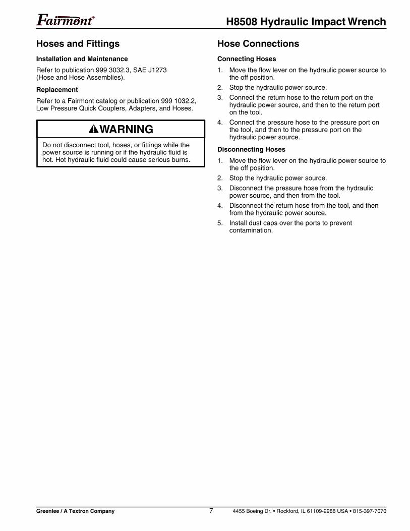
Hoses and Fittings
Installation and Maintenance
Refer to publication 999 3032.3, SAE J1273(Hose and Hose Assemblies).
Replacement
Refer to a Fairmont catalog or publication 999 1032.2,Low Pressure Quick Couplers, Adapters, and Hoses.
Hose Connections
Connecting Hoses
1. Move the flow lever on the hydraulic power source tothe off position.
2. Stop the hydraulic power source.
3. Connect the return hose to the return port on thehydraulic power source, and then to the return porton the tool.
4. Connect the pressure hose to the pressure port onthe tool, and then to the pressure port on thehydraulic power source.
Disconnecting Hoses
1. Move the flow lever on the hydraulic power source tothe off position.
2. Stop the hydraulic power source.
3. Disconnect the pressure hose from the hydraulicpower source, and then from the tool.
4. Disconnect the return hose from the tool, and thenfrom the hydraulic power source.
5. Install dust caps over the ports to preventcontamination.
Do not disconnect tool, hoses, or fittings while thepower source is running or if the hydraulic fluid ishot. Hot hydraulic fluid could cause serious burns.

H8508 Hydraulic Impact Wrench
Greenlee / A Textron Company 8 4455 Boeing Dr. • Rockford, IL 61109-2988 USA • 815-397-7070
Operation
1/2" Socket Drive Adapter and Sockets(See Figure 1)
1. Inspect quick-change chuck (7). Remove any dirt orother contamination that may have accumulated inthe chuck.
2. To insert 1/2" socket drive adapter, slide and holdquick-change chuck (7) away from tool. Insert socketdrive adapter into chuck and release chuck.
3. USE SOCKETS APPROVED FOR IMPACTWRENCH USE ONLY. Inspect 1/2" drive socket tobe installed. DISCARD SOCKET IF CRACKS,CHIPS OR GOUGES ARE EVIDENT. Install socketon socket drive adapter.
4. To remove socket drive adapter, remove socket fromadapter. Slide and hold quick-change chuck (7)away from tool. Remove socket drive adapter.
Setting Tool for Open-Center orClosed-Center Operation
All H8508 models are equipped to allow the tool to beused with either an open-center or closed-center hydrau-lic power system.
Closed-Center Hydraulic System
Hold the tool as you would when operating, observerear of trigger spool, turn center spool in trigger spool(Figure 1, Item 4) clockwise until spool stops. The tool isnow ready for closed-center operation.
Open-Center Hydraulic System
Hold the tool as you would when operating, observe rearof trigger spool (Fig. 1, Item 4), turn center spool intrigger spool counterclockwise until spool backs out tosnap-ring. The tool is now ready for open-center opera-tion.
Open-Center/Closed-Center Hydraulic System(for tools with serial numbers through 199)
Turn center spool in trigger spool (Figure 1, Item 4) sospring pin indicator points upward at the letter “C”. Thetool is now ready for closed-center operations. Turncenter spool in trigger spool so spring pin indicatorpoints downward at the letter “O”. The tool is now readyfor open-center operation.
Impact Bits
Fairmont recommends using Greenlee Impact Style Bits.
Some impact bits with a long spiral or wide flutespacing may not be acceptable to use with thistool. These bits can whip or bend under sideload.Do not use bits exhibiting these characteristicswith the H8508 Impact Wrench.
Failure to observe this warning could result insevere injury or death.
1. Inspect the drill bit to be installed. Discard the bit ifcracks, chips or gouges are evident.
2. Inspect the quick-change chuck (7). Remove any dirtor other contamination that may have accumulatedin the chuck (7).
3. Slide and hold quick-change chuck (7) away fromtool and remove drive shank (8).
4. Insert desired bit into hex socket of tool and releasechuck (7).
5. To remove drill bit, slide and hold quick-changechuck (7) away from tool and remove bit.
UPC No. Hole Dia. Overall Length Hex Shank Weight78-3310- inch mm inch mm inch mm lb g
37868 9/16 14.3 18 457 7/16 11.1 0.9 40937869 11/16 17.5 18 457 7/16 11.1 1.1 49937870 13/16 20.6 18 457 7/16 11.1 1.4 63637871 15/16 23.8 18 457 7/16 11.1 1.5 68137872 1-1/16 27.0 18 457 7/16 11.1 1.7 77237873 9/16 14.3 22 559 7/16 11.1 1.2 54537874 11/16 17.5 22 559 7/16 11.1 1.5 68137875 13/16 20.6 22 559 7/16 11.1 1.8 81737876 15/16 23.8 22 559 7/16 11.1 2.1 95337877 1-1/16 27.0 22 559 7/16 11.1 2.2 998

H8508 Hydraulic Impact Wrench
Greenlee / A Textron Company 9 4455 Boeing Dr. • Rockford, IL 61109-2988 USA • 815-397-7070
Operation (cont’d)
Wear eye protection when operatingor servicing this tool.
Failure to wear eye protection couldresult in serious eye injury fromflying debris or hydraulic oil.
Tool and drill bit may be hot duringand after operation. Contact with hotsurfaces could result in seriousinjury.
Do not reverse hydraulic flow. Operation withhydraulic flow reversed can cause tool malfunction.Connect the pressure (supply) hose and tank(return) hose to the proper ports.
Failure to observe this warning could result in severeinjury or death.
• Wear protective gloves when handling, removingand installing drill bits. Drill bits can cut even whenstationary.
• Inspect tool before use. Replace any worn,damaged, or missing parts. A damaged orimproperly assembled tool can malfunction,injuring nearby personnel.
• Inspect hydraulic hoses and couplings everyoperating day. Repair or replace if leakage,cracking, wear or damage is evident. Damagedhoses or couplings can fail resulting in injury orproperty damage.
• Use this tool for manufacturer’s intended purposeonly. Use other than that which is described in thismanual can result in injury or property damage.
• Make sure all bystanders are clear of the workarea when handling, starting and operating thetool. Nearby personnel can be injured by flying orfalling debris or by flying parts in the event of atool malfunction.
• Use only impact style bits. Bits not designed forimpact applications can break and cause severeinjury.
• Use only sockets approved for impact use.Accessories not designed for impact applicationscan break and cause severe injury.
• Inspect drill bits and sockets before use. Discarddamaged bits and sockets. Damaged accessoriescan break and cause severe injury.
• Keep all parts of the body away from rotating partswhen the tool is in operation. Contact with movingparts can result in severe injury.
• Do not change accessories, inspect, adjust orclean tool when it is connected to a power source.Accidental start-up can result in serious injury.
• Maintain a firm grip on tool, using both hands at alltimes. Serious injury can result if an operator doesnot control the tool.
• Do not lock trigger in the power-ON position.Operator can not stop tool when trigger is locked.
Failure to observe these warnings could result insevere injury or death.
Electric shock hazard:
This tool is not insulated. Whenusing this unit near energizedelectrical lines, use only certifiednonconductive hoses and properpersonal protective equipment.
Failure to observe this warning couldresult in severe injury or death.

H8508 Hydraulic Impact Wrench
Greenlee / A Textron Company 10 4455 Boeing Dr. • Rockford, IL 61109-2988 USA • 815-397-7070
Operation (cont’d)
Setup (See Figure 1)
1. Stop the power source. Disconnect tool from powersource.
2. Set open-center/closed-center spool (4) tocorrespond to the power source hydraulic system,that the tool will be connected to. See Operation—Setting Tool for Open-Center/Closed-CenterOperation.
3. Slide desired 1/2" square drive socket onto 1/2"drive on tool (8) or insert desired bit in quick-changechuck.
4. Connect the hydraulic hoses from the power sourceto the tool. Start the power source.
5. It is recommended that the power source be allowedto run (idle) for a few minutes to warm the hydraulicreservoir fluid. Actuating the tool intermittently willreduce the time required to warm the fluid to anefficient operating temperature.
Operation (See Figure 1)
1. Set reversing spool (3) to desired position(forward or reverse).Note: Never shift the reversing spool (3) while thetool is operating. Always allow the tool to come to acomplete stop before changing drill direction.Shifting the spool while the tool is operating maycause internal tool damage.
2. Grasp the trigger handle. Place your opposite handon the top of the tool. This will allow leverage to beapplied while operating.
3. To start the wrench, squeeze the trigger (2).
4. To stop the wrench, release the trigger (2).
5. After the tool has stopped rotating, lay the wrench ona flat surface.
6. When the tool is not in use, stop the power source toreduce heat and wear on the tool components.

H8508 Hydraulic Impact Wrench
Greenlee / A Textron Company 11 4455 Boeing Dr. • Rockford, IL 61109-2988 USA • 815-397-7070
Maintenance
Use this maintenance schedule to maximize the tool’sservice life.Notes: Keep all decals clean and legible, and replacewhen necessary.
When disposing of any components (hydraulic hoses,hydraulic fluid, worn parts, etc.), do so in accordancewith federal, state, and local laws or ordinances.
• Inspect tool before use. Replace any worn,damaged, or missing parts. A damaged orimproperly assembled tool can malfunction,injuring nearby personnel.
• Inspect hydraulic hoses and couplings everyoperating day. Repair or replace if leakage,cracking, wear or damage is evident. Damagedhoses or couplings can fail resulting in injury orproperty damage.
Daily
1. Wipe all tool surfaces clean.
2. Inspect the hydraulic hoses and fittings for signsof leaks, cracks, wear, or damage. Replace ifnecessary.
3. Install dust caps over the hydraulic ports when thetool is disconnected.
Monthly
Perform a thorough inspection of the hydraulic hosesand fittings as described in publication 999 3032.3,SAE J1273 (Hose and Hose Assemblies).
Quarterly
Remove the hammer case cap, anvil, impact mechanismassembly, spacer, washers and thrust bearing. Cleanthe grease from the inside of the handle cavity and allimpact components. Apply a coat of grease (MobileGrease HP) to thrust washers (48319), thrust bearing(48318), hammers (48345), hammer pins (48346) andanvil (48347) or (48397). Pack the hammer frame centerspace before pushing the anvil into the grease pocket.Reassemble components and tighten hammer case cap(48516) securely. If wrench is used under severeoperating conditions or hard-duty cycle, mechanism mayneed to be greased more often.
Semi-Annually
Drain the hydraulic system fluid. Flush out the hydraulicsystem and fill with new, clean fluid. However, if the fluidturns dark or becomes milky colored, it should bechanged as soon as possible.

H8508 Hydraulic Impact Wrench
Greenlee / A Textron Company 12 4455 Boeing Dr. • Rockford, IL 61109-2988 USA • 815-397-7070
Troubleshooting
Before You Begin
1. Tool must be connected to the correct power sourcesystem. See Tool Specification for type of hydraulicsystem required. Verify the power source hydraulicsystem.
2. Verify that the pressure and return hoses areconnected properly to the tool and power sourceports.
3. Power source reservoir must be filled to FULL levelwith hydraulic fluid.
4. Start the power source. All power source shut-offdevices must be engaged or opened (clutch en-gaged, separate on/off valves open, etc.).
5. After verifying all of the above, check the tool to seeif it operates.
If the tool does not operate, it will be necessary topinpoint the tool, hoses or power source as theproblem area. The following steps will help todetermine the problem area.
Determining the Problem Area
1. Stop the power source. Disconnect the existing toolfrom the hoses and power source.
2. Connect a known, properly operating tool to thehoses and power source. See the tool’s operator’smanual for correct hook-up procedure. Start thepower source.
If the known, properly operating tool operates, theproblem is in the disconnected tool. See the trouble-shooting charts in this operator’s manual.
If the known, properly operating tool does notoperate, the problem is likely to be in the hoses orthe power source. Proceed to Step 3.
3. Stop the power source. Disconnect the existinghoses from the known, properly operating tool andpower source.
4. Connect a different set of hoses to the known,properly operating tool and power source. Start thepower source.
If the known, properly operating tool operates withthe different set of hoses, the problem is in thedisconnected hoses.
If the known, properly operating tool does notoperate, the problem is in the power source.See your power source operator’s manual fortroubleshooting.

H8508 Hydraulic Impact Wrench
Greenlee / A Textron Company 13 4455 Boeing Dr. • Rockford, IL 61109-2988 USA • 815-397-7070
Troubleshooting (cont’d)
PROBABLE CAUSEPROBLEM POSSIBLE REMEDY
Tool inoperative. Tool connected to improper power See Tool Specifications for type ofsource hydraulic system. hydraulic system required. Verify
power source hydraulic system.
No hydraulic fluid in system or Check fluid level. Fill to FULL mark.fluid level low. Check system for leaks.
Incorrect hydraulic fluid viscosity. Use fluid viscosity recommended.See Recommended Hydraulic Fluids.
Tool components loose. Tighten component hardware.
Dirt, contaminants, etc., in tool Disassemble tool and cleancomponents. components.
Tool components worn or damaged. Disassemble tool. Replace worn ordamaged components.
Hose connections to power source Depressurize hydraulic system.reversed. Reverse hose connections.
Tool operates erratically. Hydraulic fluid cold. Viscosity of fluid may be too high atstart of tool operation. Allow fluid towarm to operating temperature.Actuating tool intermittently will reducetime required to warm fluid to anefficient operating temperature.
Air in system. Check pump suction line for damageor loose clamps. Tighten clamps orreplace components, if necessary.Fill reservoir.
Tool components sticking or Check for dirt or gummy deposits.binding. Clean components. Check for worn
or damaged components. Replacecomponents.
Dirt, contaminants, etc., in tool Disassemble tool and cleancomponents. components.

H8508 Hydraulic Impact Wrench
Greenlee / A Textron Company 14 4455 Boeing Dr. • Rockford, IL 61109-2988 USA • 815-397-7070
Troubleshooting (cont’d)
PROBABLE CAUSEPROBLEM POSSIBLE REMEDY
Tool impacts slowly. Power source components not Refer to power source operator’sadjusted correctly. manual for recommended speed,
flow, and pressure settings.
Hydraulic fluid cold. Viscosity of fluid may be too high atstart of tool operation. Allow fluid towarm to operating temperature.Actuating tool intermittently will reducetime required to warm fluid to anefficient operating temperature.
Hydraulic fluid level low. Check fluid level. Fill to FULL mark.Check system for leaks.
Hydraulic fluid viscosity too heavy. Use fluid viscosity recommended.See Recommended Hydraulic Fluids.
Tool components loose. Tighten component hardware.
Dirt, contaminants, etc., in tool Disassemble tool. Cleancomponents. components.
Tool components worn or damaged. Disassemble tool. Replace worn ordamaged components.
Damaged hose couplings. Inspect couplings. Replace ifdamaged.
Tool operates too fast. Power source components not Refer to power source operator’sadjusted correctly. manual for recommended speed,
flow, and pressure settings.
Tool components sticking or binding. Check for dirt or gummy deposits.Clean components. Check for wornor damaged components. Replacecomponents.

H8508 Hydraulic Impact Wrench
Greenlee / A Textron Company 15 4455 Boeing Dr. • Rockford, IL 61109-2988 USA • 815-397-7070
Troubleshooting (cont’d)
PROBABLE CAUSEPROBLEM POSSIBLE REMEDY
Tool feels hot. Hydraulic fluid level low. Check fluid level. Fill to FULL mark.Check system for leaks.
Hydraulic fluid viscosity too light. Use fluid viscosity recommended.See Recommended Hydraulic Fluids.
Hydraulic fluid dirty. Drain reservoir, flush and fill withclean fluid. Change filter.
Tool control valve stuck in partial Free valve so it returns to neutralpower-ON position. position.
Power source components not Refer to power source operator'sadjusted correctly. manual for recommended speed,
flow, and pressure settings.
Dirt, contaminants, etc., in tool Disassemble tool. Cleancomponents. components.
Worn or damaged O-rings or gaskets. Replace worn or damaged O-ringsor gaskets.
Tool components worn or damaged. Disassemble tool. Replace worn ordamaged components.

H8508 Hydraulic Impact Wrench
Greenlee / A Textron Company 16 4455 Boeing Dr. • Rockford, IL 61109-2988 USA • 815-397-7070
Troubleshooting (cont’d)
PROBABLE CAUSEPROBLEM POSSIBLE REMEDY
Tool leaks hydraulic fluid. Tool components loose. Tighten component hardware.
Worn or damaged O-rings or gaskets. Replace worn or damaged O-ringsor gaskets.
Tool components worn or damaged. Disassemble tool. Replace worn ordamaged components.
Tool trigger plunger sticks or Check for dirt or gummy deposits. Clean components.works hard.
Trigger binding (trigger bent, trigger Inspect, adjust trigger where bindingpivot pin too tight, etc.). occurs.
Power source works, but tool Inappropriate hydraulic system. Check type of hydraulic power source.lacks power or does not operate. open-center or closed-center.
Power source works, but tool Relief valve setting in tool not correct. Return tool to factory for service.lacks power and/or impactsslowly.
Tool appears to operate Impact mechanism dry. Grease has Regrease impact mechanism.normally but lacks impact been thrown off. See the Maintenance Schedule sectionpower or does not drill. of this manual.
Incorrect grease or overpacked. Regrease impact mechanism.See the Maintenance Schedule sectionof this manual.
Grease leaks at anvil Heavy duty cycle, heat caused Normal, mechanism may requirebushing, wrench warm. grease to liquify. grease more often, see the
Maintenance Schedule section ofthis manual.

H8508 Hydraulic Impact Wrench
Greenlee / A Textron Company 17 4455 Boeing Dr. • Rockford, IL 61109-2988 USA • 815-397-7070
Disassembly
Complete disassembly of the tool is not recommended.Return the tool to your nearest authorized Fairmontdistributor or to the factory.
The disassembly procedure is divided into sections ofthe tool. Complete disassembly of the tool is seldomnecessary. Disassemble only the areas necessary tocorrect the problem. See Exploded View and Parts Listfor identification of parts as they are removed.
Disassembly should be done on a flat, clean surface.Some parts may fall free during disassembly. To preventpart loss or damage, keep the tool as close to theworking surface as possible.
Inspect all parts as they are disassembled and matingparts in the tool that are not removed for signs of dam-age, wear, cracks, etc. Replace any parts which appearto be damaged.
When disassembling tool for service it is recommendedthat O-rings, back-up rings and gaskets be replaced.
Quick-Change Chuck (See Figure 7)
1. Remove adapter (61) from retaining sleeve (50).
2. Press on thrust ring (52) to expose thrust ring lock(51). Remove thrust ring lock (51) thrust ring (52)and spring (53). Slide retaining sleeve (50) off anvil(49) and remove the two steel balls (54).
3. Remove the second thrust ring lock (51) if anvil (49)needs to be removed from hammer case cap (55).Note: To prevent the loss of any steel balls, it isrecommended to perform this step over a clean,empty container to catch any components that mayfall free.
Note: If either thrust ring (51) becomes sprung orout-of-round during disassembly, discard andreplace with a new ring.
Hammer Case Components
1. Using flats provided on hammer case cap (55)unscrew cap and remove from tool.
The remaining impact mechanism parts can now beremoved from tool (items 46, 47 and 48).
2. Remove spacer (45), thrust bearing (43) and thrustwashers (44) from hammer case cavity.
Motor (See Figures 6, 7, and 9)
1. Remove socket head cap screws (16) and pullmotor cap (6) from handle (1). Remove gasket (15).If necessary, remove dowel pins (14).
2. Pull idler shaft (13) with gear (10) from handle.Remove gear (10) from idler shaft (13). If necessary,remove drive pin (12) and retaining clip (11) fromidler shaft (13).
3. Remove retaining clip (11) gear (10) and Woodruffkey (9) from drive shaft (8). Push drive shaft (8)toward hammer case cavity and remove from handle(1).
Bearing Replacement
Note: If bearings in motor cap (6) or bearings inhandle (1) are damaged or worn, Fairmont recommendsreplacing the component as an assembly with thebearings already pressed in or return it to Fairmontfor repair.
Skin injection hazard:
Oil under pressure easily puncturesskin, causing serious injury,gangrene, or death. If you are injuredby escaping oil, seek medicalattention immediately.
• Do not use hands to check forleaks.
• Do not hold hose or couplers whilethe hydraulic system is pressurized.
• Depressurize the hydraulic systembefore servicing.
Do not disconnect tool, hoses, or fittings while thepower source is running or if the hydraulic fluid ishot. Hot hydraulic fluid could cause serious burns.
Procedure for connecting or disconnecting hydraulichoses, fittings, or components:
1. Move the flow lever on the hydraulic powersource to the off position.
2. Stop the hydraulic power source.
3. Follow the sequence under “Hose Connections”to prevent pressure buildup. In case somepressure has built up, loosen hoses, fittings, orcomponents slowly.

H8508 Hydraulic Impact Wrench
Greenlee / A Textron Company 18 4455 Boeing Dr. • Rockford, IL 61109-2988 USA • 815-397-7070
Disassembly (cont’d)
Trigger and Control Spool—48696(See Figures 7 and 8)
48273 (48330/48329 prior to S/N 300)(See Figures 4 and 7)
1. Remove spring pin (42) from trigger spool (29) bypressing or tapping with a hammer and punch.Note: Support trigger (41) so pressing or tappingdoes not bend trigger spool (29).
2. Remove washer (39), spring (38), snap ring (37),and washer (36). Trigger spool (29) may now bepushed out of handle (1). Push spool toward triggerside of tool.
3. Remove snap ring (33). open-center/closed-centerspool (31) may now be removed to service O-ring(34). (O-ring [30] prior to S/N 300)
4. Ball (32) is loose in this assembly. Take caution tocatch ball when it falls free. (No ball [32] prior toS/N 300)
Reversing Spool
1. Remove reversing spool (19) by loosening andremoving cap (24) on left side of tool and pullingspool (19) out right side of tool.Note: For tool orientation (left and right) grip tool asyou would use it and view tool looking at motor cap(6). See Figure 6.
Note: Attempting to push the reversing spool (19)the opposite way through the bore will causedamage to O-rings (25 and 26) and could allowparticles of O-ring to get into motor.
2. Remove plug (22), spring (21) and poppet (20).
3. Repeat procedure for right side of reversingspool (19).Note: If set screws (23 and 60) have not beendisturbed and internal components are returned tothe same side of spool (19),the relief valve settingmay not have been affected and tool will performproperly when assembled.
Note: Relief valve setting may require checkingwhen tool is reassembled.
Assembly
Inspection
1. Motor Cap (6) and Handle (1). Mating surfaces, gearcavities, oil passageways, etc.; must be smooth andfree of grooves or nicks. If either component hasgrooves or nicks, replace the component as anassembly with the bearings already pressed in.
2. Drive Shaft (8), Idler Shaft (13) and Gears (10). Allsurfaces, including gear teeth, must be smooth andfree of grooves or nicks. If any component isdamaged, replace the component.
3. Bearing (3 and 7). Hold motor cap or handle assem-bly in one hand or place on a flat surface. Insertdrive shaft (8) or idler shaft (13) into bearing. Spinthe shaft. The shaft should turn smoothly. If anyroughness is noted, Fairmont recommends replacingthe component as an assembly with the bearingsalready pressed in.
4. Bearing (56) in hammer case cap (55). Slide anvil(49) into bearing (56). Turn anvil (49). The anvilshould turn smoothly. If any roughness is noted,check anvil surface. If problem is the bearing sur-face, replace hammer case cap assembly as anassembly with the bearing already pressed in.
5. Thrust bearing (43) and thrust washers (44). Turnbearing on washer surfaces. Bearing should rollsmoothly. If any roughness is felt, replace thecomponents.
6. Trigger Spool (29). All surfaces must be free ofgrooves or nicks. If the component has grooves ornicks, replace the component.
7. Reversing Spool (19). All surfaces must be free ofgrooves or nicks. If the component has grooves ornicks, replace the component.
8. Hammer Frame (46), Anvil (49), Hammers (47) andPins (48). All surfaces must be free of grooves,nicks, or cracks. If any component has grooves,nicks, or cracks, replace the component.
9. O-rings. Always replace O-rings in components thathave been disassembled with new O-rings duringassembly. A packing kit is available that includes allO-rings and gaskets.
10. Gasket (15). Always replace gaskets when motorcap or hammer case is removed from handleassembly. Install new gasket (15).

H8508 Hydraulic Impact Wrench
Greenlee / A Textron Company 19 4455 Boeing Dr. • Rockford, IL 61109-2988 USA • 815-397-7070
Figure 3Torque Sequence
When assembling parts, refer to the Illustrations andParts Lists for correct orientation and placement of parts.
Clean grease and oil from all parts (take care to protecteyes), then dry thoroughly. Do not expose O-rings orother packing components to cleaning agent for longperiods of time.
Inspect all parts as they are assembled for signs ofdamage, wear, cracks, etc. Do not install any partswhich appear to be damaged.
Apply hydraulic fluid or O-ring lubricant to all O-rings andall metal surfaces which O-rings must slide over. Wheninstalling an O-ring over a sharp edge, use a rollingaction to avoid damage to O-ring.
Wherever assembled parts cause metal-to-metal con-tact, coat the surfaces with hydraulic fluid or O-ringlubricant.
Motor (See Figures 6, 7 and 9)
1. Install new O-ring (4) and back-up ring (5) into driveshaft opening of handle (1) using an O-ring tool.Be careful, do not damage O-ring during installation.
2. Lubricate drive shaft (8) and slide into opening inhandle (1) through the O-rings and back-up ring fromimpact mechanism side of tool.
3. Install Woodruff key (9) and one gear (10) onto driveshaft (8), guiding keyway in gear (10) over Woodruffkey (9). Fasten gear to drive shaft with retaining clip(11).
4. Install drive pin (12) into idler shaft (13), if removed.Slide remaining gear (10) onto idler shaft (13),guiding keyway in gear (10) over drive pin (12).Install idler shaft and gear into handle (1), meshingthe two gears (10) together. Use retaining clip (11) torestrain lateral movement of idler shaft.
5. Install dowel pins (14) into handle (1) if removed.Install new gasket (15).
6. Install motor cap (6) onto handle (1).
7. Secure motor cap (6) to handle (1) with cap screws(16). Torque cap screws (16) to 80 inch-pounds.Follow torque sequence shown in Figure 3.
Reversing Spool (See Figure 5)
1. Install O-ring (25) onto reversing spool (19).Replace O-ring (26) in handle (1).
2. Install O-ring (30) on plug (22). At O-ring end ofspool (19) install poppet (20), spring (21) and plug(22). Secure assembly with cap (24).
3. Slide reversing spool assembly into handle (1), asshown in Figure 5.
4. Install poppet (20), spring (21) and plug (22) intoopposite end of spool (19). Secure with cap (24).Use two wrenches on cap (24) and tighten to23 foot-pounds.
Trigger, Trigger Spool, andOpen-Center/Closed-Center Spool(See Figures 7 and 8)
48330/48329 prior to S/N 300 (See Figures 4 and 7)
1. Install O-ring (34) (O-ring (30) prior to S/N 300) onopen-center/closed-center spool (31). Install ball (32)in trigger spool (29) cavity. (No ball (32) priorto S/N 300.) Install open-center/closed-center spool(31) into trigger spool (29). Secure with snap-ring(33).
2. Install O-ring (35) onto trigger spool assembly.Replace O-ring (27) and back-up ring (28) inhandle (1).
3. Slide trigger spool assembly as shown in Figure 4or 8 into handle (1) from trigger side of tool.
48330/48329 prior to S/N 300 (See Figures 4 and 7)
Note: Slots in trigger spool (29) must be facing handleend of tool.
1. Slide washer (36) onto trigger spool (29) and securewith snap-ring (37).
2. Slide spring (38) and washer (39) onto triggerspool (29).
3. Secure trigger (41) to trigger spool (29) with springpin (42).
4. Secure link (40) to handle (1) and trigger (41) withspring pins (42).Note: Support trigger (41) so pressing or tapping onspring pins (42) does not bend trigger spool (29).
Assembly (cont’d)
1
3
4
2
5 7
8 6

H8508 Hydraulic Impact Wrench
Greenlee / A Textron Company 20 4455 Boeing Dr. • Rockford, IL 61109-2988 USA • 815-397-7070
Assembly (cont’d)
Hammer Case Components
Note: Grease required for assembly of impactmechanism = Mobil Grease HP.
1. Apply grease to thrust bearing (43) and work intoneedle rollers. Apply light film of grease to thrustwashers (44), stack thrust washers and thrustbearing properly and place over drive shaft (8).
2. Place spacer (45) over drive shaft (8) with flangepart of spacer up.
Impact Mechanism
1. Before assembly, grease surfaces of hammer frame(46), hammers (47) hammer pin (48) and anvil (49).
2. Install the two hammers (47) 180° from each other,into hammer frame (46). Install pins (48) into ham-mer frame and through the hammers, then slideassembly onto spline of drive shaft (8).
3. Pack hammer frame (46) center space with grease.Install anvil (49) into hammer frame (46) and throughhammers (47).
4. Install O-ring (62) over threads on hammer casecap (55).
5. Slide hammer case cap assembly (55 and 56) overanvil (49) and using flats on cap (55) screw intohandle (1), tighten securely.Note: Apply lubrication to threads.
Quick-Change Chuck
1. Slide thrust ring lock (51) over anvil (49) to grooveclosest to hammer case cap (55).
2. Insert two balls (54) into holes in anvil (49). Slideretaining sleeve (50) onto anvil (49) “Open” side up.Insert spring (53) and thrust ring (52) into retainingsleeve (50). Depress thrust ring (52) and installthrust ring lock (51) on anvil (49). This will secureretaining sleeve (50) to anvil (49). Insert drive shank(61) into chuck.Note: If either thrust ring (51) becomes sprung orout-of-round during disassembly, discard andreplace with a new ring.
Figure 4Spool shown in Closed-Center Position
Models 48330/48329(effective through serial number 299)
35
2930
31
33

H8508 Hydraulic Impact Wrench
Greenlee / A Textron Company 21 4455 Boeing Dr. • Rockford, IL 61109-2988 USA • 815-397-7070
58 57
1718
16
5959
C
O
Illustration
Models 48330/48329(effective through serial number 299)
20
24
22
23
19
21
26
60
Install Spool ThisDirection
Remove Spool ThisDirection
2530
Figure 6
Figure 5

H8508 Hydraulic Impact Wrench
Greenlee / A Textron Company 22 4455 Boeing Dr. • Rockford, IL 61109-2988 USA • 815-397-7070
Illustration (cont’d)
Models 48330/48329 (effective through serial number 299)
51
55
52
54
56
62 40
4239
41
1
3837
3635
29
53
54
61
50
49
51
4647
8
4544
43
5 4
15
3 1410
6
9
1211
11
713
1027
28
33
30
31
48
Figure 7

H8508 Hydraulic Impact Wrench
Greenlee / A Textron Company 23 4455 Boeing Dr. • Rockford, IL 61109-2988 USA • 815-397-7070
Key UPC No. Part No. Description Qty.
1 48309 HANDLE ASSEMBLY ....................................................................... 1
Handle, Insulated .............................................................................. 1
Expander Plug................................................................................... 1
3 41591 F016728 Bearing .............................................................................................. 2
4 48707 48706 O-Ring ............................................................................................... 1
5 48306 Back-up Ring..................................................................................... 1
6 48356 MOTOR CAP .................................................................................... 1
7 41591 F016728 Bearing .............................................................................................. 2
8 48279 Drive Shaft ........................................................................................ 1
9 41592 F016729 Key .................................................................................................... 1
10 41630 F017105 11-Tooth Gear ................................................................................... 2
11 41621 F017010 Snap Ring ......................................................................................... 2
12 41593 F016730 Drive Pin............................................................................................ 1
13 40168 104110K Idler Shaft .......................................................................................... 1
14 41624 F017014 Dowel Pin .......................................................................................... 2
15* 48363 Gasket ............................................................................................... 1
16 41889 F021674 Socket Hd Cap Screw ....................................................................... 8
17 48328 Eye .................................................................................................... 1
18 43701 F021676 Socket Hd Cap Screw ....................................................................... 1
48382 REVERSING SPOOL ASSEMBLY ................................................... 1
19 48361 Reversing Spool ................................................................................ 1
20 48515 Poppet ............................................................................................... 2
21 48543 Spring ................................................................................................ 2
22 48621 Plug ................................................................................................... 2
23 905 0765.7 Set Screw .......................................................................................... 2
24 48380 Cap.................................................................................................... 2
60 48622 Set Screw .......................................................................................... 2
25* 41491 F015261 O-Ring ............................................................................................... 1
26* 41426 F013565 O-Ring ............................................................................................... 1
27* 48539 F011743 O-Ring ............................................................................................... 1
28* 43312 F021451 Back-up Ring..................................................................................... 1
48273 TRIGGER, SPOOL ASSEMBLY ....................................................... 1
29 48272 Spool-Trigger .................................................................................... 1
30* 41384 F011060 O-Ring ............................................................................................... 3
31 48275 OC/CC SPOOL ASSEMBLY ............................................................. 1
OC/CC Spool .................................................................................... 1
Spring Pin .......................................................................................... 1
33 48540 F021711 Snap Ring ......................................................................................... 1
35* 41491 F015261 O-Ring ............................................................................................... 1
36 48310 Washer .............................................................................................. 1
37 41648 F017595 Snap Ring ......................................................................................... 1
38 48311 Spring ................................................................................................ 1
39 48312 Washer .............................................................................................. 1
Parts List
Models 48330/48329 (effective through serial number 299)

H8508 Hydraulic Impact Wrench
Greenlee / A Textron Company 24 4455 Boeing Dr. • Rockford, IL 61109-2988 USA • 815-397-7070
40 48313 Link .................................................................................................... 1
41 48360 Trigger ............................................................................................... 1
42 48542 F015810 Spring Pin .......................................................................................... 3
43 48318 Thrust Bearing................................................................................... 1
44 48319 Thrust Washer ................................................................................... 2
45 48364 Spacer ............................................................................................... 1
48516 HAMMER CASE CAP ASSEMBLY
55 48320 Hammer Case Cap ........................................................................... 1
56 48517 Bearing .............................................................................................. 1
57 43550 158055 Decal—Safety ................................................................................... 1
58 48512 Decal—Pressure/Flow ...................................................................... 1
59 48513 Decal—ID .......................................................................................... 2
62* 41803 F020780 O-Ring ............................................................................................... 1
For Model 48330 Only
48343 IMPACT MECHANISM
46 48344 Hammer Frame ................................................................................. 1
47 48345 Hammer ............................................................................................ 2
48 48346 Hammer Pin ...................................................................................... 2
49 48347 Anvil—Quick Change ........................................................................ 1
50 48348 Retaining Sleeve ............................................................................... 1
51 48349 Thrust Ring Lock ............................................................................... 2
52 48350 Thrust Ring ........................................................................................ 1
53 48351 Sleeve Spring .................................................................................... 1
54 48352 Ball .................................................................................................... 2
61 41515 F015321 Adapter .............................................................................................. 1
For Model 48329 Only
48398 IMPACT MECHANISM
46 48344 Hammer Frame ................................................................................. 1
47 48345 Hammer ............................................................................................ 2
48 48346 Hammer Pin ...................................................................................... 2
49 48397 Anvil—1/2" Sq. Drive ......................................................................... 1
Kit
* 48538 Seal Kit
Parts List (cont’d)
Key UPC No. Part No. Description Qty.
Models 48330/48329 (effective through serial number 299)

H8508 Hydraulic Impact Wrench
Greenlee / A Textron Company 25 4455 Boeing Dr. • Rockford, IL 61109-2988 USA • 815-397-7070
Illustration
Models 48330/48329 (effective with serial number 300)
Figure 9
58 57
1718
16
5959
C
O
Figure 8Spool shown in Open-Center Position
35
29
34
31
32
33

H8508 Hydraulic Impact Wrench
Greenlee / A Textron Company 26 4455 Boeing Dr. • Rockford, IL 61109-2988 USA • 815-397-7070
Illustration (cont’d)
Models 48330/48329 (effective with serial number 300)
51
55
52
54
56
62 40
4239
41
1
3837
3635
29
53
54
61
50
49
51
4647
8
4544
43
5 4
15
3 1410
6
9
1211
11
713
1027
28
33
34
31
32
48
Figure 10

H8508 Hydraulic Impact Wrench
Greenlee / A Textron Company 27 4455 Boeing Dr. • Rockford, IL 61109-2988 USA • 815-397-7070
Key UPC No. Part No. Description Qty.
1 48309 HANDLE ASSEmbly ......................................................................... 1
41591 F016728 Bearing .............................................................................................. 2
4 48706 O-Ring ............................................................................................... 1
5 48306 Back-up Ring..................................................................................... 1
6 48307 MOTOR CAP .................................................................................... 1
7 41591 F016728 Bearing .............................................................................................. 2
8 48279 Drive Shaft ........................................................................................ 1
9 41592 F016729 Key .................................................................................................... 1
10 41630 F017105 11-Tooth Gear ................................................................................... 2
11 41621 F017010 Snap Ring ......................................................................................... 2
12 41593 F016730 Drive Pin ............................................................................................ 1
13 40168 104110K Idler Shaft .......................................................................................... 1
14 41624 F017014 Dowel Pin .......................................................................................... 2
15* 48363 Gasket ............................................................................................... 1
16 41889 F021674 Socket Hd Cap Screw ....................................................................... 8
17 48328 Eye .................................................................................................... 1
18 43701 F021676 Socket Hd Cap Screw ....................................................................... 1
48382 REVERSING SPOOL ASSEmbly ..................................................... 1
19 48361 Reversing Spool ................................................................................ 1
20 48515 Poppet ............................................................................................... 2
21 48543 Spring ................................................................................................ 2
22 48621 Plug ................................................................................................... 2
23 905 0765.7 Set Screw .......................................................................................... 2
24 48380 Cap.................................................................................................... 2
60 48622 Set Screw .......................................................................................... 2
25* 42050 F023449 O-Ring ............................................................................................... 1
26* 48889 O-Ring ............................................................................................... 1
27* 48539 F011743 O-Ring ............................................................................................... 1
28* 43312 F021451 Back-up Ring..................................................................................... 1
29 48696 Spool-Trigger .................................................................................... 1
30* 42047 F023379 O-Ring ............................................................................................... 2
31 48697 OC/CC Spool .................................................................................... 1
32 43829 F021411 Ball .................................................................................................... 1
33 48540 F021711 Snap Ring ......................................................................................... 1
34* 41331 F010777 O-Ring ............................................................................................... 1
35* 41491 F015261 O-Ring ............................................................................................... 1
36 48310 Washer .............................................................................................. 1
37 41648 F017595 Snap Ring ......................................................................................... 1
38 48311 Spring ................................................................................................ 1
39 48312 Washer .............................................................................................. 1
40 48313 Link.................................................................................................... 1
41 48360 Trigger ............................................................................................... 1
42 48542 F015810 Spring Pin .......................................................................................... 3
43 48318 Thrust Bearing................................................................................... 1
Parts List
Models 48330/48329 (effective with serial number 300)

H8508 Hydraulic Impact Wrench
Greenlee / A Textron Company 28 4455 Boeing Dr. • Rockford, IL 61109-2988 USA • 815-397-7070
Parts List (cont’d)
Key UPC No. Part No. Description Qty.
44 48319 Thrust Washer ................................................................................... 2
45 48364 Spacer ............................................................................................... 1
48516 HAMMER CASE CAP ASSEMBLY
55 48320 Hammer Case Cap ........................................................................... 1
56 48517 Bearing .............................................................................................. 1
57 43550 158055 Decal—Safety ................................................................................... 1
58 48512 Decal—Pressure/Flow ...................................................................... 1
59 48513 Decal—ID .......................................................................................... 2
62* 41803 F020780 O-Ring ............................................................................................... 1
For Model 48330 Only
48343 IMPACT MECHANISM
46 48344 Hammer Frame ................................................................................. 1
47 48345 Hammer ............................................................................................ 2
48 48346 Hammer Pin ...................................................................................... 2
49 48347 Anvil—Quick-Change ........................................................................ 1
50 48348 Retaining Sleeve ............................................................................... 1
51 48349 Thrust Ring Lock ............................................................................... 2
52 48350 Thrust Ring ........................................................................................ 1
53 48351 Sleeve Spring .................................................................................... 1
54 48352 Ball .................................................................................................... 2
61 41515 F015321 Adapter .............................................................................................. 1
For Model 48329 Only
48398 IMPACT MECHANISM
46 48344 Hammer Frame ................................................................................. 1
47 48345 Hammer ............................................................................................ 2
48 48346 Hammer Pin ...................................................................................... 2
49 48397 Anvil—1/2" Sq. Drive ......................................................................... 1
Kit
* 48538 Seal Kit
Models 48330/48329 (effective with serial number 300)
H8508 Hydraulic Impact Wrench
Greenlee / A Textron Company 29 4455 Boeing Dr. • Rockford, IL 61109-2988 USA • 815-397-7070
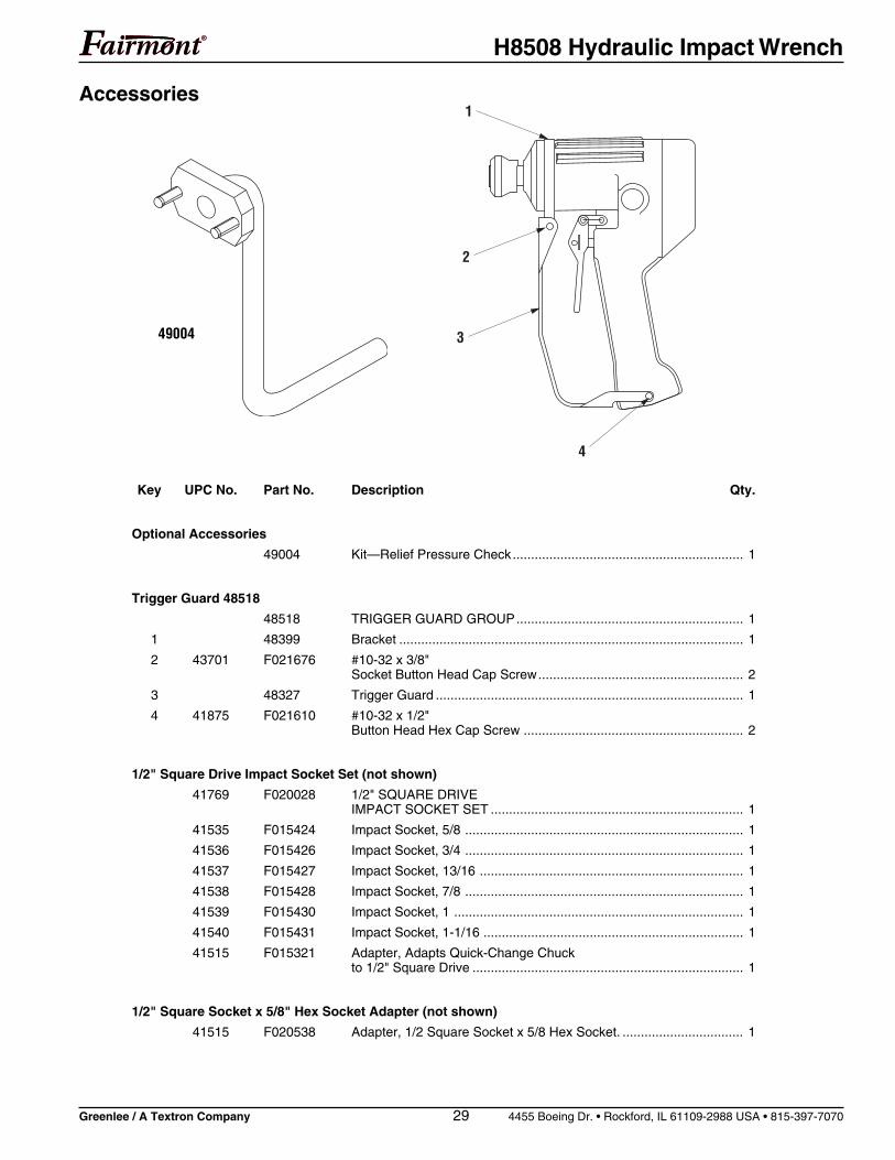
Accessories
Key UPC No. Part No. Description Qty.
Optional Accessories
49004 Kit—Relief Pressure Check............................................................... 1
Trigger Guard 48518
48518 TRIGGER GUARD GROUP.............................................................. 1
1 48399 Bracket .............................................................................................. 1
2 43701 F021676 #10-32 x 3/8"Socket Button Head Cap Screw........................................................ 2
3 48327 Trigger Guard .................................................................................... 1
4 41875 F021610 #10-32 x 1/2"Button Head Hex Cap Screw ............................................................ 2
1/2" Square Drive Impact Socket Set (not shown)
41769 F020028 1/2" SQUARE DRIVEIMPACT SOCKET SET ..................................................................... 1
41535 F015424 Impact Socket, 5/8 ............................................................................ 1
41536 F015426 Impact Socket, 3/4 ............................................................................ 1
41537 F015427 Impact Socket, 13/16 ........................................................................ 1
41538 F015428 Impact Socket, 7/8 ............................................................................ 1
41539 F015430 Impact Socket, 1 ............................................................................... 1
41540 F015431 Impact Socket, 1-1/16 ....................................................................... 1
41515 F015321 Adapter, Adapts Quick-Change Chuckto 1/2" Square Drive .......................................................................... 1
1/2" Square Socket x 5/8" Hex Socket Adapter (not shown)
41515 F020538 Adapter, 1/2 Square Socket x 5/8 Hex Socket. ................................. 1
1
2
3
4
49004

USA 800-435-0786 Fax: 800-451-2632 815-397-7070 Fax: 815-397-1865Canada 800-435-0786 Fax: 800-524-2853International +1-815-397-7070 Fax: +1-815-397-9247
4455 Boeing Drive • Rockford, IL 61109-2988 • USA • 815-397-7070An ISO 9001 Company • Greenlee Textron Inc. is a subsidiary of Textron Inc.
www.greenlee.com Printed in USA