h-h1h%h h$h!h. nsr series h*h/h.h%>Ì??%? ? … · - 2 - do not bend, alter or damage the rail....
TRANSCRIPT
NSIR MAE01
QUICHERNSRI Type
Automatic Screw Feeder
www.ohtake-root.co.jp HP
www.ohtake-root.co.jp
ATTENTION : www.ohtake-root.co.jp is the only web site associated with our company. We do not have any branches in China.
Operation Manual
Read these instructions for the proper use of this machine.
After having read these instructions,
keep them in a convenient place so you
or the operator can refer to them whenever necessary.
自動ネジ供給機
NSR Series
Automatic Screw Feeder
NSR1MA01
(Maintenance)
02M
- 1 -
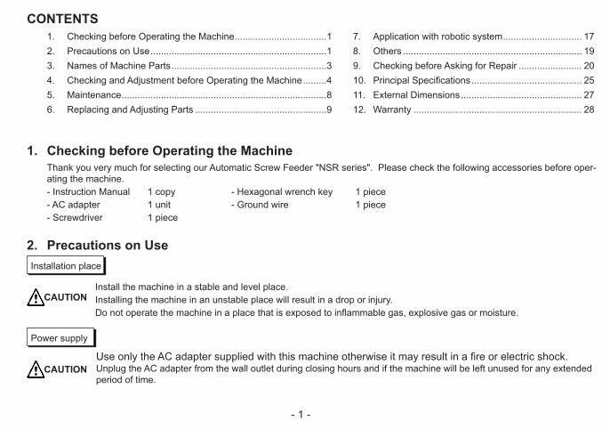
1. Checking before Operating the MachineThank you very much for selecting our Automatic Screw Feeder "NSR series". Please check the following accessories before oper-ating the machine.- Instruction Manual 1 copy - Hexagonal wrench key 1 piece- AC adapter 1 unit - Ground wire 1 piece- Screwdriver 1 piece
2. Precautions on Use
Install the machine in a stable and level place. Installing the machine in an unstable place will result in a drop or injury. Do not operate the machine in a place that is exposed to inflammable gas, explosive gas or moisture.
Installation place
CAUTION
Use only the AC adapter supplied with this machine otherwise it may result in a fire or electric shock.Unplug the AC adapter from the wall outlet during closing hours and if the machine will be left unused for any extended period of time.
Power supply
CAUTION
1. Checking before Operating the Machine ...................................12. Precautions on Use ...................................................................13. Names of Machine Parts ...........................................................34. Checking and Adjustment before Operating the Machine .........45. Maintenance ..............................................................................86. Replacing and Adjusting Parts ..................................................9
CONTENTS7. Application with robotic system .............................. 178. Others .................................................................... 199. Checking before Asking for Repair ........................ 2010. Principal Specifications .......................................... 2511. External Dimensions .............................................. 2712. Warranty ................................................................ 28
- 2 -
Do not bend, alter or damage the rail. Do not apply any oil. We recommend the user to clean the rail periodically.
Rail
Do not use any screw that is out of the specified range or any screw that is stained with oil or dust.
Screws that must not be used
When picking up screws, do not exert excessive force or shock to the screws.
Precautions on picking up screws
Do not attempt to repair, disassemble or modify this machine except where specified by this manual. Consult your dealer for service of this machine.
Repair
Do not allow any foreign material to enter into the machine while it is in operation. Do not put fingers into the machine while it is in operation, otherwise an injury will result.
Handling during operation
CAUTION
When any abnormality is found while the machine is in operation, pull out the AC adapter from the plug socket. If the machine operation is continued in the abnormal status, it will cause a fire, electric shock, or injury. When an ab-normality is detected, consult your dealer.
Abnormality during operation
CAUTION
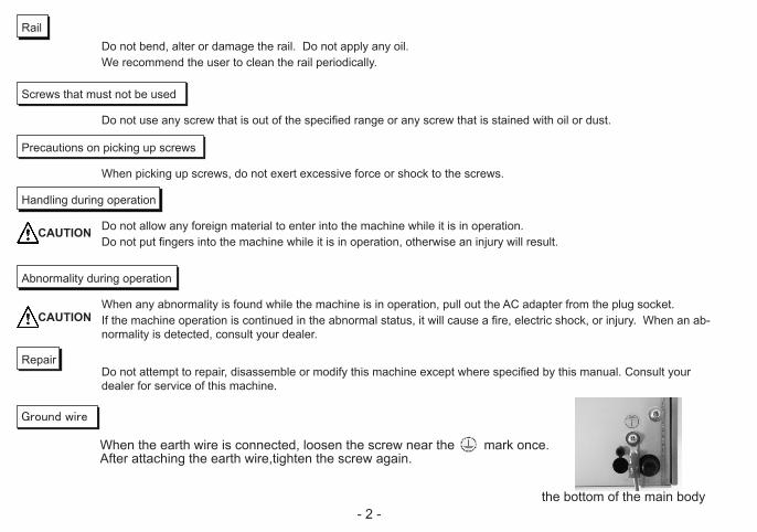
Ground wire
When the earth wire is connected, loosen the screw near the mark once.After attaching the earth wire,tighten the screw again.
the bottom of the main body
- 3 -
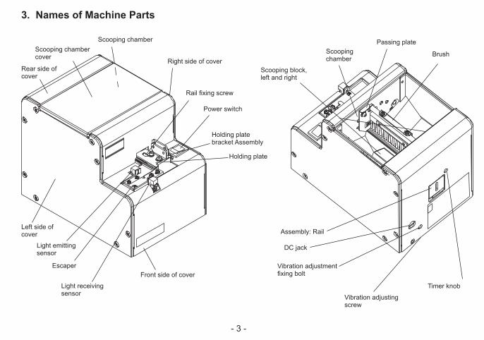
3. Names of Machine Parts
Scooping chamber cover
Scooping chamber
Rail fixing screw
Holding plate bracket Assembly
Holding plate
Light emitting sensor
Light receiving sensor
Power switch
Front side of cover
Rear side of cover
Left side of cover
Right side of cover
Assembly: Rail
Escaper
Passing plate
Brush
DC jack
Timer knob
Vibration adjusting screw
Scooping chamber
Scooping block, left and right
Vibration adjustment fixing bolt
- 4 -
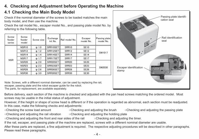
4.1 Checking the Main Body ModelCheck if the nominal diameter of the screws to be loaded matches the main body model, and then use the machine.Check the rail model No., escaper model No., and passing plate model No. by referring to the following table.
Before delivery, each section of the machine is checked and adjusted with the pan head screws matching the ordered model. Most screws may be usable in the initial status of adjustment.However, if the height or shape of screw head is different or if the operation is regarded as abnormal, each section must be readjusted. In this case, make the following checks and adjustments:○Checking the screw load amount ○Checking and adjusting the brush ○Checking and adjusting the passing plate○Checking and adjusting the rail vibration ○Checking and adjusting the holdiing plate○Checking and adjusting the front and rear sides of the rail ○Checking and adjusting the timer.If the rail, escaper, and passing plate of the machine are replaced, screws with a different nominal diameter are usable.After these parts are replaced, a fine adjustment is required. The respective adjusting procedures will be described in other paragraphs. Please read these paragraphs.
Passing plate identifi-cation seal
Rail identification seal
Escaper identification stamp
4. Checking and Adjustment before Operating the Machine
Reference table of the specified screws
Screwfeederseries
Screwfeedermodel
Screw sizeExchange
kit No.Rail model No.
Escapermodel No.
Passing platemodel No.
Screwsize
Screw shaftdiameter(φ )
Screwhead
diameter(φ )
Screwhead
thickness(mm)
Screwshaftlength(mm)
SemsDoublesems
Washerhead
NSR10 φ 1.0 SRR10SET SRR10 SE10 φ 1.0 0.9~0.95 1.2~4.5 0.35~1.0 1.6~10 ○
NSR12 φ 1.2 SRR12SET SRR12 SE12 φ 1.2 1.1~1.15 1.4~4.5 0.35~1.0 1.8~10 ○
NSR14 φ 1.4 SRR14SET SRR14 SE14 φ 1.4 1.3~1.4 1.7~4.5 0.35~1.0 2.0~10 ○
NSR17 φ 1.7 SRR17SET SRR17 SE17 φ 1.7 1.6~1.7 2.0~4.5 0.35~1.0 2.3~10 ○
NSR20 φ 2.0 SRR20SET SRR20 SE20 φ 2.0 1.9~2.1 2.4~6 0.35~4.5 2.6~20 ○ ○ ○ ○ ○ ○ ○
NSR23 φ 2.3 SRR23SET SRR23 SE23 φ 2.3 2.2~2.4 2.7~6 0.35~4.5 2.9~20 ○ ○ ○ ○ ○ ○ ○
NSR26 φ 2.6 SRR26SET SRR26 SE26 φ 2.6 2.5~2.7 3.0~6 0.35~4.5 3.2~20 ○ ○ ○ ○ ○ ○ ○
NSR30 φ 3.0 SRR30SET SRR30 SE30 φ 3.0 2.9~3.2 3.5~6 0.35~4.5 3.6~20 ○ ○ ○ ○ ○ ○ ○
NSR
SW1017
SW2030
Shape of screw headPan head
bind Flat headCountersunk head
hexagonflangebolt
Note: Screws, with a different nominal diameter, can be used by replacing the rail,escaper, passing plate and the robot escaper guide for the robot.The parts, for replacement, are available separately.
- 5 -
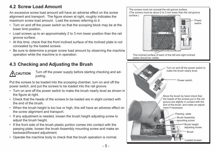
4.2 Screw Load AmountAn excessive screw load amount will have an adverse effect on the screw alignment and transport. The figure shown at right, roughly indicates the maximum screw load amount. Load the screws referring to it.• Turn on and off the power switch so that the scooping block may be at the
lower limit position.• Load screws up to an approximately 2 to 3 mm lower position than the rail
groove surface.• At this time, check that the front inclined surface of the inclined plate is not
concealed by the loaded screws.• Be sure to determine a proper screw load amount by observing the machine
operation while the machine is in operation.
4.3 Checking and Adjusting the BrushTurn off the power supply before starting checking and ad-justing.
Put the screws to be loaded into the scooping chamber, turn on and off the power switch, and put the screws to be loaded into the rail groove.• Turn on and off the power switch to make the brush nearly level as shown in
the figure at right.• Check that the heads of the screws to be loaded are in slight contact with
the end of the brush.• When the brush height is too low or high, this will have an adverse effect on
the screw alignment and transport.• If any adjustment is needed, loosen the brush height adjusting screw to
adjust the brush height.• If the front side of the brush plastic portion comes into contact with the
passing plate, loosen the brush Assembly mounting screw and make an backward/forward adjustment.
• Operate the machine body to check that the brush operation is normal.
CAUTION
The screws must not conceal the rail groove surface.(The screws must be about 2 to 3 mm lower than the rail groove surface.)
Power switch
This inclined surface of each of the left and right inclined plates should be visible.
Turn on and off the power switch to make the brush nearly level.
Power switch
Move the brush by hand check that the heads of the screws put in the rail groove are slightly in contact with the end of the brush, and make an adjust-ment if necessary.
Passing plateBrush Assembly mounting screw
Brush height adjusting screw
Brush
Loaded screws
- 6 -
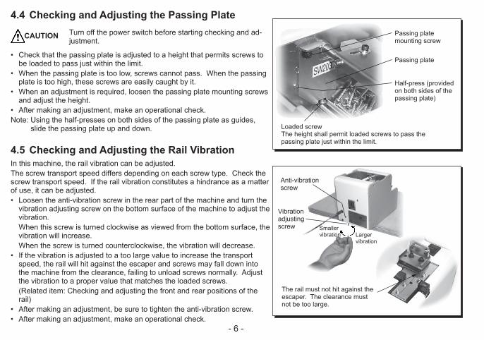
4.4 Checking and Adjusting the Passing PlateTurn off the power switch before starting checking and ad-justment.
• Check that the passing plate is adjusted to a height that permits screws to be loaded to pass just within the limit.
• When the passing plate is too low, screws cannot pass. When the passing plate is too high, these screws are easily caught by it.
• When an adjustment is required, loosen the passing plate mounting screws and adjust the height.
• After making an adjustment, make an operational check.Note: Using the half-presses on both sides of the passing plate as guides,
slide the passing plate up and down.
4.5 Checking and Adjusting the Rail VibrationIn this machine, the rail vibration can be adjusted.The screw transport speed differs depending on each screw type. Check the screw transport speed. If the rail vibration constitutes a hindrance as a matter of use, it can be adjusted.• Loosen the anti-vibration screw in the rear part of the machine and turn the
vibration adjusting screw on the bottom surface of the machine to adjust the vibration.
When this screw is turned clockwise as viewed from the bottom surface, the vibration will increase.
When the screw is turned counterclockwise, the vibration will decrease.• If the vibration is adjusted to a too large value to increase the transport
speed, the rail will hit against the escaper and screws may fall down into the machine from the clearance, failing to unload screws normally. Adjust the vibration to a proper value that matches the loaded screws.
(Related item: Checking and adjusting the front and rear positions of the rail)
• After making an adjustment, be sure to tighten the anti-vibration screw.• After making an adjustment, make an operational check.
CAUTION Passing plate mounting screw
Passing plate
Half-press (provided on both sides of the passing plate)
Loaded screwThe height shall permit loaded screws to pass the passing plate just within the limit.
Anti-vibration screw
Vibration adjusting screw Smaller
vibration Larger vibration
The rail must not hit against the escaper. The clearance must not be too large.
- 7 -
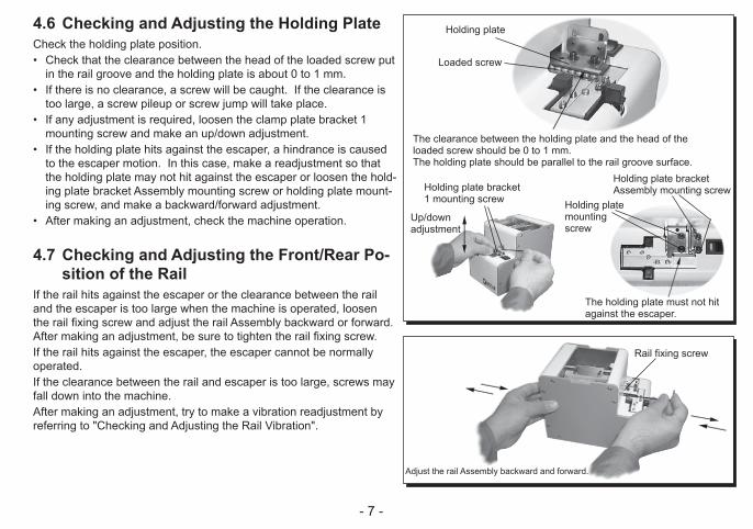
4.6 Checking and Adjusting the Holding PlateCheck the holding plate position.• Check that the clearance between the head of the loaded screw put
in the rail groove and the holding plate is about 0 to 1 mm.• If there is no clearance, a screw will be caught. If the clearance is
too large, a screw pileup or screw jump will take place.• If any adjustment is required, loosen the clamp plate bracket 1
mounting screw and make an up/down adjustment.• If the holding plate hits against the escaper, a hindrance is caused
to the escaper motion. In this case, make a readjustment so that the holding plate may not hit against the escaper or loosen the hold-ing plate bracket Assembly mounting screw or holding plate mount-ing screw, and make a backward/forward adjustment.
• After making an adjustment, check the machine operation.
4.7 Checking and Adjusting the Front/Rear Po-sition of the Rail
If the rail hits against the escaper or the clearance between the rail and the escaper is too large when the machine is operated, loosen the rail fixing screw and adjust the rail Assembly backward or forward. After making an adjustment, be sure to tighten the rail fixing screw.If the rail hits against the escaper, the escaper cannot be normally operated. If the clearance between the rail and escaper is too large, screws may fall down into the machine.After making an adjustment, try to make a vibration readjustment by referring to "Checking and Adjusting the Rail Vibration".
Holding plate
Loaded screw
The clearance between the holding plate and the head of the loaded screw should be 0 to 1 mm. The holding plate should be parallel to the rail groove surface.
Holding plate bracket 1 mounting screw
Up/down adjustment
Holding plate bracket Assembly mounting screw
Holding plate mounting screw
The holding plate must not hit against the escaper.
Rail fixing screw
Adjust the rail Assembly backward and forward.

- 8 -
4.8 Checking and Adjusting the TimerThe screw transport speed differs depending on each screw type.This machine can make screw unloading smooth through timer adjustment. For screws with a low transport speed, set the timer long. For screws with a high transport speed, set the timer short.• This machine continues its operation when no screw is found at the screw
unloading position, and holds a screw at the screw unloading position, and stops its operation after the lapse of a certain time. When the screw at the screw unloading position is taken out, the machine restarts its operation. This time can be varied by adjusting the timer.
• Check the operation by intercepting the optical axis of the sensor.• Make an adjustment with the timer knob at the rear of the machine body as
shown in the figure at right.• When the timer knob is turned clockwise as viewed from the rear side, the
time becomes shorter. When this knob is turned counterclockwise, the time becomes longer.• Make this adjustment within the allowable turning range without giving ex-
cessive force.• Make an operational check by using loaded screws and set the timer prop-
erly.
5. MaintenanceIf the rail groove becomes dirty, the loaded screw transport speed may be slow. In case the rail groove is very dirty, clean it with a thin and clean cloth dipped in alcohol. If cleaning is difficult, detach the rail from the main body and clean the rail groove. If the rail is detached from the main body, be sure to turn off the power supply and take out loaded screws in the scooping chamber before-hand.If there is any dirt or a flaw in the rail groove that may cause an impediment to use, we recommend the user to replace the rail.
Loosen the rail fixing screw, and the rail can be detached from the rear side of the main body.
Clean the rail groove.
Rail fixing screw
Adjust the timer with the timer knob.
Longer
Shorter
When the optical axis of the sensor is inter-cepted, the timer will function to stop the operation of the main body.
Timer knob

- 9 -
6. Replacing and Adjusting PartsThe brush, main motor, and escaper motor are consumables. The replacement rail, passing plate required after a change of nominal diameter of loaded screw, rail, and escaper must be ordered separately. The replacing and adjusting procedures are described below.When replacing parts after changing the nominal diameter, especially, a fine adjustment is required. Make this fine adjustment by read-ing the corresponding contents carefully.Take out all the loaded screws put in the main body before starting the parts replacement work.
6.1 Replacing and Adjusting the BrushTurn off the power switch before starting replacement and adjustment.
If the end of the brush is too worn out to sweep out the screws of abnormal posture, replace the brush with a new one.A more bristly brush than the standard brush is available as an option. Make use of it when necessary.• Turn on and off the power switch of the main body. Set the brush at the
position shown in the figure at right and detach the brush Assembly. (Set the brush Assembly mounting screw to an easy-to-detach position.)• The brush Assembly can be disassembled as shown in the figure at right.• For assembly, reverse the disassembling procedure.• After completion of assembly, check that when the brush Assembly is
operated, the front side of the brush plastic portion may not hit against the passing plate. The ideal clearance is zero.
• For adjustment, refer to "Checking and Adjusting before Operating the Machine".
Part number of brush assembly: − NSB 02053 #01 (standard part) − NSB 02053 #02 (option: a more bristly brush)
CAUTIONBrush Assembly mounting screw
Passing plate
Brush Assembly
Passing plate Brush
When the brush is operated, it should not hit against the passing plate.
(exploded view)

- 10 -
6.2 Replacing the Main Motor
Turn off the power switch before starting to replace and adjust the main motor.
When the motor is damaged, please replace it with a new one.
• Remove the cover from the main body. (In the case of the front cover with the power switch, disconnect the con-
nector of the power switch and then detach this front cover from the main body.)
• Disconnect the motor junction connector.• Remove the motor mounting screws on the bottom of the main body.• Pull out the motor from the rear side of the main body. (At this time, if the motor is hard to pull out, insert a hexagonal wrench key
into the oblong hole of the main body base and push the motor mounting bracket backward.)
• For assembly into the main body, reverse the disassembling procedure. However, the relation with the operation timing is shown on the next page.
Note: To avoid wire breakage, do not use excessive force with the motor wir-ing.
Welding: Part No. of main motor unit NSB 03056
CAUTION
a. Remove the cover. b. Disconnect the junction connector.
c. Remove the motor bracket mounting screws.
d. Pull out the motor.
Main motor unit

- 11 -
Operation Timing in Replacing the Main MotorTurn off the power switch before starting to replace and adjust the main motor.
• To adjust the scooping block to the brush in respect of operation timing, it is necessary to adjust the gear engagement.
• When the motor has been removed from the main body, adjust the gear engagement of the motor as shown in the figure at right, and the operation timing can be adjusted.
• When it is hard to engage the driving gear of the motor with the driven gear, remove the escaper Assembly mounting screws and put it on the left side.
After that, when the installed driving shaft bracket (right) is loosened, this will facilitate the assembly work. (Refer to the figure at right.)
After installing the motor, be sure to tighten the loosened screws once again. Readjust the escaper Assembly.
• After installing the motor, energize the motor and check the operation tim-ing.
(Check that both left and right scooping blocks can be operated almost simultaneously.)
• After making an operation check, return the wire arrangement to its original status.
When installing the cover, take care not to cause the wire to be caught. Give consideration so that the wiring may not be a hindrance to the opera-
tion of this machine. The wiring should not be a hindrance when adjustments are made from the
outside.
Note: To avoid wire breakage, do not use excessive force with the motor wir-ing.
CAUTION The left and right scooping blocks should be at the low-est position.
When the right pin is vertical, the left pin should be inclined about 46°.
Escaper Assembly mounting screw (2 pieces each on the left and right sides)
In the status where the left and right scooping blocks are at the lowest position, install the motor.
If it is hard to obtain proper gear engagement, loosen only the right driving shaft bracket.
Put the escaper Assembly on the left side.
Right driving shaft bracket
Mounting screws at 4 positions

- 12 -
6.3 Replacing the Escaper MotorTurn off the power switch before starting to replace and adjust the escaper motor.
When the motor is damaged, replace it with a new one.• Remove the cover from the main body. (In the case of the front cover with power switch, remove the connector of
the power switch and detach it from the main body.)• Disconnect the motor junction connector.• Remove the 4 escaper Assembly mounting screws and detach the escaper
Assembly from the main body.• Remove three escaper mounting screws, and remove the escaper retainer. • Remove two escaper motor mounting screws. The escaper is moved to
right-hand side, and a left-hand side screw removes it. • Attach a new escaper motor. Backlash is adjusted and it fixes so that the
escaper may return smoothly by means of a spring. • For assembly into the main body, reverse the disassembling procedure. At
installation, the escaper must be adjusted.• After making an operation check, return the wire arrangement into its origi-
nal status. When installing the cover, take care not to cause the wire to be caught by it. Give consideration so that the wiring may not be a hindrance to the operation of this machine.
Note: To avoid wire breakage, do not use excessive force with the motor wir-ing.
Welding: Part No. of escaper motor NSR 08653
CAUTION
a. Remove the cover.
c. Remove the escaper Assembly.
b. Disconnect the junction connector.
Junction connector
Mounting screw (2 pieces each on the left and right side)
Escaper Assembly
d. Remove the escaper retainer
In order to remove a screw, a escaper is brought near by right-hand side.
e.Remove the escaper motor.

- 13 -
6.4 Replacing the Rail AssemblyTurn off the power supply before starting to replace and adjust the rail Assembly.
The rail Assembly of this machine can be easily replaced.When there is any dirt or a flaw on the rail groove that may constitute a hin-drance to the operation, we recommend the user to replace the rail.When using screws with a different nominal diameter, replace the rail Assem-bly as well as the escaper and passing window as a means.Before replacement and adjustment, take out the loaded screws in the ma-chine. Loosen the rail fixing screws and pull out the rail Assembly from the rear side of this machine.After replacing the rail, each portion must be adjusted.
6.5 Replacing the Passing PlateTurn off the power supply before starting to replace and adjust the passing plate.
For using screws with a different nominal diameter, replace the passing plate as well as the rail and escaper as a means.Remove the passing plate mounting screws, then remove the passing plate. Take care not to loosen the mounting screws.At installation, use the half-press on each of both sides of the passing plate as a guide.
After replacement, it is necessary to make an adjustment in accordance with loaded screws.
CAUTION
CAUTION
Loosen the rail fixing screws, and the rail can be removed from the rear side of the main body.
Rail fixing screw
Passing plate Mounting screwHalf-press (provided on each of both sides of the passing plate)

- 14 -
6.6 Replacing and Adjusting the EscaperTurn off the power supply before starting to replace and adjust the escaper.
For using screws with a different nominal diameter, replace the escaper as well as the rail and passing plate as a means.
Replace and adjust the escaper after removing the cover.Replace the escaper after removing the escaper mounting screws. After replacement, be sure to adjust and check the parts related to the es-caper.
Adjust the escaper on the basis of the rail. In the direction of height, the rail groove surface should be lower than the escaper surface and counter-screw surface should be lower than the escaper surface.In the direction of width, the rail groove should be adjusted to the escaper groove in operation and also the rail side surface should not make contact with the counter-screw end surface.In addition, adjust the sensor level in the status where no screws are loaded.
① Adjust the height of the escaper surface.
Install the escaper. At this time, the mounting screw should be positioned in the center of the oblong hole.
Adjust the height of the escaper retainer so that the escaper surface may be equal to or a little lower than to the rail groove surface. At this time, move the escaper to right so that the escaper surface may slide in parallel to the rail groove surface.
CAUTION Names of main partsCounter-screw
Counter-screw mounting screw
Escaper
Light receiv-ing sensor
Counter-screw bracket mounting screw
Light receiving sensor mounting screw
Escaper retainer mounting screw
Driving gear
Escaper Assembly mounting screw
Escaper mount-ing screw
Rail fixing screwRail
The mounting screw should be positioned in the center of the oblong hole.
The escaper surface should be lower than the rail groove surface.
Make an adjustment so that the escaper surface may slide in parallel to the rail groove surface.
When the escaper is moved right, the escaper surface should be lower than the rail groove surface.

- 15 -
② Adjust the escaper groove position.
Adjust the escaper groove position so that when the escaper is moved to the right side until it hits against the stopper, the rail groove may be aligned with the escaper groove.
For a rough adjustment, loosen the 2 escaper Assembly mounting screws on each of both left and right sides. For a fine adjustment, loosen the 2 escaper mounting screws.
After completion of the above adjustments, move the escaper to the right side until it hits against the stopper and check the groove position once again.
③ Adjust the counter-screw surface position
Loosen the counter-screw mounting screws and adjust the clearance between the rail side surface and the counter-screw end face. This clearance should be such that does not cause a collision when the rail is vibrated.
Loosen the counter-screw bracket mounting screws and adjust the height of the counter-screw surface.
This height should be equal to or a little lower than to the escaper surface.
When the escaper is moved and hits against the stopper, the rail groove should be aligned with the escaper groove.
Rough adjustment
Fine adjustment Move the escaper
Adjust the clearance between the rail and the counter-screw.
Adjust the height of the counter-screw surface.
The ideal clearance between the rail and the counter-screw is about 0.1. This clearance may be larger if the nominal diameter of screw is large.
Rail groove surface height > Escaper surface height > Counter-screw surface height

- 16 -
④ Adjust the sensor voltage level.
Adjust the sensor voltage level for the case where no loaded screws are in the escaper unloading section.
For the voltage level,measure the pin No.7 of IC4050 on the main board.
Be sure to ground the metal portion of the main body.
Adjust the sensor voltage level to 0.25 V to 1.5 V in the status where no loaded screws are in the escaper unloading section.
Note: When no loaded screws are: 0.25 V to 1.5 V When loaded screws are: 3.5 V or more Electrically, it is judged by using 2.5 V as a boundary whether loaded
with screws or not.
After checking and adjusting each portion, make an operational check of the machine actually with loaded screws.
If any abnormality is found, make the said adjustment once again in addition to the rail vibration and front/rear position adjustments.
After completion of the operational check, return the wiring arrangement to its original status.
When installing the cover, take care not to cause the wire to be caught by it.
Give consideration so that the wiring may not be a hindrance to the operation of this machine.
When there are no loaded screws, the voltage value should be 0.25 V to 1.5 V.
Loosen the light receiving sensor mounting screw (at 2 positions) and adjust the light receiving sensor up and down.
Check the voltage level of pin No.7 of IC4050

- 17 -
7- 1. External output signalsThe wires coming out from the back of the machine serves as the detection of presence of screws on the rotational escaper, which shall be used with automatic assembly machines or external screw coun-ters. Signal line
7. Application with Robotic System
CN10
Purple line
Gray line
Example of connection[Function]: Screw present: signal high (ON) Incoming current: shall be limited to less than 100mA **CAUTION: Additional resistor is required on external circuit for regulating current **[Capacity]: Max DC current: 100mA External supply voltage: 5 ~24VDC (Max: 27VDC)[caution]: Please keep the length of output signal wire less than 3m;* The purple wire functions as signal output high (Collector end), with the gray wire as common (Emitter end)
Purple line--->Signal line (OFF when no screw is present) (On when a screw is present)Gray line --->Common line
Inseide of the feeder
Outseide of the feeder

- 18 -
7- 3. Robotic OperationsWhen the screw feeder is used with an automatic assembly system, in order to avoid contacts between screw driver and screw feeder , please set the lowest point of the bit at least 0.3mm above the screw, so that contact or collision of the driver bit and screw feeder can be avoided.
7- 2. Installation with Robotic System
When installed with a robotic assembly, the screw feeder shall be fastened by lower edges of the cover. (Please refer to diagram on the right side) Fastening screws on bottom edge of the cover can be used for this purpose as well.In addition, if the rubber supports shall be replaced with fastening assemblies by the user, please keep length of the screws less than 5mm going inside the machine, in order to prevent damage to inter-nal mechanism of the screw feeder.
Fixing method
Fixing screws (M2.6)
マウスピース
ビット
ネジ
ネジの頭の高さ
+ 0.3mm
供給機の破損防止の
ための隙間
0.3
Bit cover
Driver bit
Screw
0 . 3 m m a b o v e s c r e w head to prevent collision or damage to the screw feeder

- 19 -
8. Others8.1 Overload Protective CircuitThis machine is provided with an overload protective circuit.Usually, the driving motor rotates forward (normal rotation) to feed loaded screws to the escaper continuously, thus picking up screws one after another. However, if an overload is applied to the driving section, the driving motor rotates backward for a certain time and then returns to the normal rotation. When the cause of the overload is removed at the reverse rotation, the driving motor returns to the ordinary normal rotation and can pick up screws.If the cause of the overload is not removed during the reverse rotation, the driving motor repeats the sequence of reverse rotation - normal rotation - reverse rotation - normal rotation for a certain time to shut off the power to the driving motor. At this time, the escaper operation is not stopped.When the power to the driving motor is shut off, turn off the power switch and remove the cause of the overload. For example, when too many screws are put into the scooping chamber, reduce the quantity of loaded screws to a proper level. If any screw is caught by the driving section, remove it. After removing the cause of the overload, turn on the power switch to operate this machine. (Power reset)
Fixing screws (M2.6)

- 20 -
9. Checking before Asking for RepairFor safety, always unplug the AC adapter from the wall outlet before making any adjustments.
Cause Corrective Measures
- Power is not supplied.
- The machine has not unloaded screws from the unloading section for a certain time.
- Too many screws were put into the scoop-ing chamber.
- A foreign material (for example, screw) was put in the main body.
- The AC adapter is faulty.
- Screws with a larger nominal diameter than the specified nominal rail size were loaded or screws with a different diameter were mixed in together.
- An insufficient quantity of screws are in the scooping chamber.
- Check the connection of the power supply of the AC power adapter.
- Take out the screws from the unloading section.
- Adjust the timer setting knob.
- Reduce the quantity of screws in the scooping chamber to a proper level.
- Remove the foreign material.
- Please contact your dealer.
- Use screws with the specified nominal diameter.
- Remove the mixed screws.
- Add a proper quantity of screws into the scooping chamber.
CAUTION
9.1 The machine does not oper-ate though the power switch is turned on.
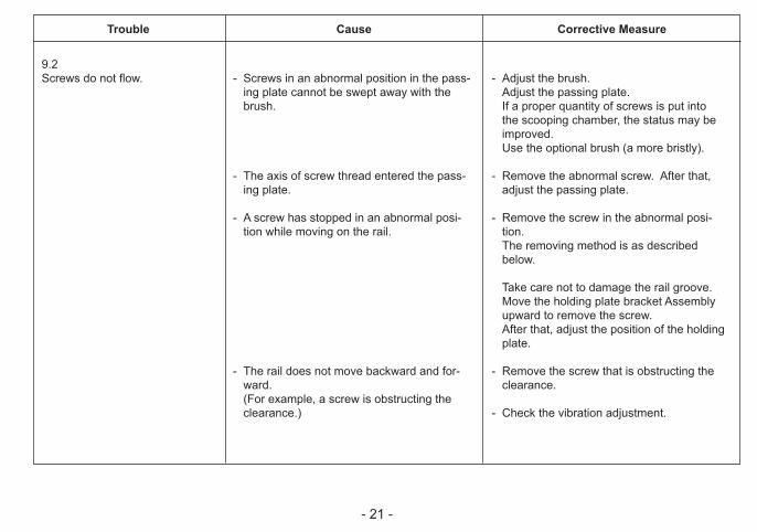
9.2 Screws do not flow.
Trouble
- 21 -
Cause Corrective Measure
- Screws in an abnormal position in the pass-ing plate cannot be swept away with the brush.
- The axis of screw thread entered the pass-ing plate.
- A screw has stopped in an abnormal posi-tion while moving on the rail.
- The rail does not move backward and for-ward.
(For example, a screw is obstructing the clearance.)
- Adjust the brush. Adjust the passing plate. If a proper quantity of screws is put into
the scooping chamber, the status may be improved.
Use the optional brush (a more bristly).
- Remove the abnormal screw. After that, adjust the passing plate.
- Remove the screw in the abnormal posi-tion.
The removing method is as described below.
Take care not to damage the rail groove. Move the holding plate bracket Assembly
upward to remove the screw. After that, adjust the position of the holding
plate.
- Remove the screw that is obstructing the clearance.
- Check the vibration adjustment.
9.2 Screws do not flow.
Trouble

- 22 -
Cause Corrective Measure
- Screws with a smaller nominal diameter than the specified nominal rail size were loaded.
- Screws with a smaller total length than the rail groove width were loaded.
- The clearance between the holding plate and the head of the loaded screw is narrow.
- Screws with spring washer having one-step smaller than the specified nominal rail size were loaded.
- Dust or oil is stuck on the rail.
- The rail does not vibrate. (A screw is caught in the clearance.)
- The motor is exhausted.
- Use screws with the specified nominal diameter.
- No corrective measure is available. Consult our service section.
- Adjust the holding plate bracket Assembly. (Adjust the hplding plate.) Adjust the vibration. Operate this machine in an inclined status.
- Clean the rail.
- Remove the screws caught in the clear-ance.
- Check that the vibration is properly ad-justed.
- Replace the motor.
9.3A screw has fallen down into the rail groove.
9.4 The screw flow on the rail is improper.
Trouble

- 23 -
Cause Corrective Measure
- The passing plate is not adjusted properly.
- Too many screws are in the scooping cham-ber.
- Screws are stopped while still on the rail.- Screws cannot be transferred smoothly
from the rail to the escaper.
- The overload protective circuit was actu-ated.
- Too many screws are in the scooping cham-ber.
- A screw is caught in the clearance.
- Screws in the unloading section could not be unloaded for a certain time.
- Adjust the passing plate.
- Reduce the quantity of screws into a proper level.
- Adjust the position of the holding plate.
- Adjust the positional relation between the end of the rail and the escaper.
- Turn the machine off and on once again.- Remove the cause of overload.
- Reduce the quantity of screws to a proper level.
- Remove the caught screw.
- Take out screws.
9.5 Screws tend to pass the passing plate in an abnormal position.The axis of screw thread tends to enter the passing plate.
9.6 No screw comes to the unload-ing section.
9.7 This machine stops its operation suddenly.
Trouble
- 24 -
Cause Corrective Measure
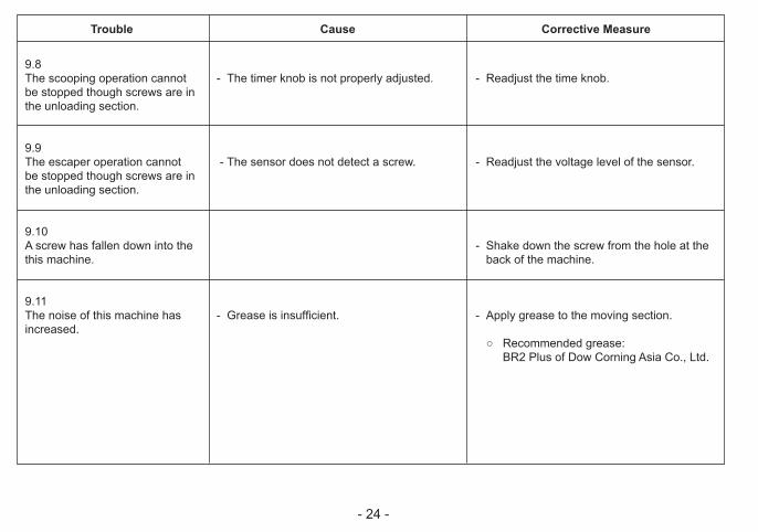
- The timer knob is not properly adjusted.
- The sensor does not detect a screw.
- Grease is insufficient.
- Readjust the time knob.
- Readjust the voltage level of the sensor.
- Shake down the screw from the hole at the back of the machine.
- Apply grease to the moving section.
○ Recommended grease: BR2 Plus of Dow Corning Asia Co., Ltd.
9.8 The scooping operation cannot be stopped though screws are in the unloading section.
9.9 The escaper operation cannot be stopped though screws are in the unloading section.
9.10 A screw has fallen down into the this machine.
9.11 The noise of this machine has increased.
Trouble

- 25 -
※ Conpatible wth washer diameter up to 9 mm, thickness 0.35 to 1.0mm.
10.SpecificationsNotes:- Check if the axis diameter of the loaded screw matches the above rail
groove width.- In the main body type, the main body model can be changed.- To change the nominal diameter of loaded screw, replace it with a part
that is mentioned in the above table.- The rail, escaper, and passing plate for replacement are separately
available.- The design, performance, and specifications are subject to change
without prior notice for the sake of improvement.
Reference table of the specified screws
Screwfeederseries
Screwfeedermodel
Screw sizeExchange
kit No.Rail model No.
Escapermodel No.
Passing platemodel No.
Screwsize
Screw shaftdiameter(φ )
Screwhead
diameter(φ )
Screwhead
thickness(mm)
Screwshaftlength(mm)
SemsDoublesems
Washerhead
NSR10 φ 1.0 SRR10SET SRR10 SE10 φ 1.0 0.9~0.95 1.2~4.5 0.35~1.0 1.6~10 ○
NSR12 φ 1.2 SRR12SET SRR12 SE12 φ 1.2 1.1~1.15 1.4~4.5 0.35~1.0 1.8~10 ○
NSR14 φ 1.4 SRR14SET SRR14 SE14 φ 1.4 1.3~1.4 1.7~4.5 0.35~1.0 2.0~10 ○
NSR17 φ 1.7 SRR17SET SRR17 SE17 φ 1.7 1.6~1.7 2.0~4.5 0.35~1.0 2.3~10 ○
NSR20 φ 2.0 SRR20SET SRR20 SE20 φ 2.0 1.9~2.1 2.4~6 0.35~4.5 2.6~20 ○ ○ ○ ○ ○ ○ ○
NSR23 φ 2.3 SRR23SET SRR23 SE23 φ 2.3 2.2~2.4 2.7~6 0.35~4.5 2.9~20 ○ ○ ○ ○ ○ ○ ○
NSR26 φ 2.6 SRR26SET SRR26 SE26 φ 2.6 2.5~2.7 3.0~6 0.35~4.5 3.2~20 ○ ○ ○ ○ ○ ○ ○
NSR30 φ 3.0 SRR30SET SRR30 SE30 φ 3.0 2.9~3.2 3.5~6 0.35~4.5 3.6~20 ○ ○ ○ ○ ○ ○ ○
NSR
SW1017
SW2030
Shape of screw headPan head
bind Flat headCountersunk head
hexagonflangebolt
Input:AC100~240V 50/60Hz
Output:DC15V 1A
Dimensions 123(W) × 181(D) × 145(H) (mm)
Weight Approx. 3.0Kg (including rail)
Screw capacity Approx. 80cc
Followingaccessories
Operation Manual 1 copyAC Adapter 1 unitHexagonal Wrench 1 pieceScrewdriver 1 pieceGround wire 1 piece
PowerAC adapter
(switching type)
- 26 -
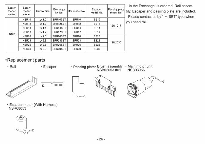
・ Escaper motor (With Harness) NSR08053
Reference table of the specified screws
Screwfeederseries
Screwfeedermodel
Screw sizeExchange
kit No.Rail model No.
Escapermodel No.
Passing platemodel No.
Screwsize
Screw shaftdiameter(φ )
Screwhead
diameter(φ )
Screwhead
thickness(mm)
Screwshaftlength(mm)
SemsDoublesems
Washerhead
NSR10 φ 1.0 SRR10SET SRR10 SE10 φ 1.0 0.9~0.95 1.2~4.5 0.35~1.0 1.6~10 ○
NSR12 φ 1.2 SRR12SET SRR12 SE12 φ 1.2 1.1~1.15 1.4~4.5 0.35~1.0 1.8~10 ○
NSR14 φ 1.4 SRR14SET SRR14 SE14 φ 1.4 1.3~1.4 1.7~4.5 0.35~1.0 2.0~10 ○
NSR17 φ 1.7 SRR17SET SRR17 SE17 φ 1.7 1.6~1.7 2.0~4.5 0.35~1.0 2.3~10 ○
NSR20 φ 2.0 SRR20SET SRR20 SE20 φ 2.0 1.9~2.1 2.4~6 0.35~4.5 2.6~20 ○ ○ ○ ○ ○ ○ ○
NSR23 φ 2.3 SRR23SET SRR23 SE23 φ 2.3 2.2~2.4 2.7~6 0.35~4.5 2.9~20 ○ ○ ○ ○ ○ ○ ○
NSR26 φ 2.6 SRR26SET SRR26 SE26 φ 2.6 2.5~2.7 3.0~6 0.35~4.5 3.2~20 ○ ○ ○ ○ ○ ○ ○
NSR30 φ 3.0 SRR30SET SRR30 SE30 φ 3.0 2.9~3.2 3.5~6 0.35~4.5 3.6~20 ○ ○ ○ ○ ○ ○ ○
NSR
SW1017
SW2030
Shape of screw headPan head
bind Flat headCountersunk head
hexagonflangebolt
○Replacement parts・ Rail ・ Passing plate・ Brush assembly
NSB02053 #01・ Main motor unit NSB03056
・ Escaper
- In the Exchange kit ordered, Rail assem-bly, Escaper and passing plate are included.- Please contact us by “ ~ SET” type when you need rail.

- 27 -
11. External Dimensions
Unit : mm※ Height till top of esscaper
※85
.4
A
ネジ呼び径A寸法の目安
φ 1.0 22.6φ 1.2 22.5φ 1.4 22.4φ 1.7 22.2φ 2.0 22.1φ 2.3 21.9φ 2.6 21.8φ 3.0 21.6
Screw sizeApproximatemeasurement
of Aφ 1.0 22.6φ 1.2 22.5φ 1.4 22.4φ 1.7 22.2φ 2.0 22.1φ 2.3 21.9φ 2.6 21.8φ 3.0 21.6
- 28 -
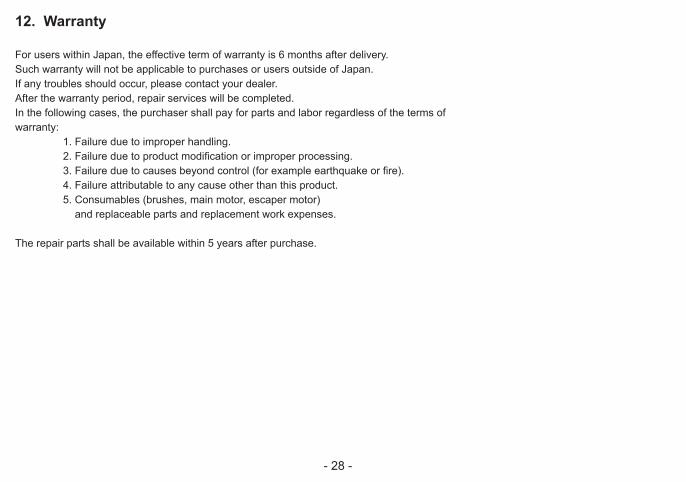
12. Warranty
For users within Japan, the effective term of warranty is 6 months after delivery.Such warranty will not be applicable to purchases or users outside of Japan.If any troubles should occur, please contact your dealer.After the warranty period, repair services will be completed.In the following cases, the purchaser shall pay for parts and labor regardless of the terms ofwarranty: 1. Failure due to improper handling. 2. Failure due to product modification or improper processing. 3. Failure due to causes beyond control (for example earthquake or fire). 4. Failure attributable to any cause other than this product. 5. Consumables (brushes, main motor, escaper motor) and replaceable parts and replacement work expenses.
The repair parts shall be available within 5 years after purchase.

- 29 -
「Quicher」 「OHTAKE」 「OHTAKE ・ ROOT KOGYO」 are trademarks or/and registered trademarks of OHTAKE ・ ROOT KOGYO CO.LTD.]「Quicher( クイッチャー)」 「OHTAKE」 「OHTAKE ・ ROOT KOGYO」 は、 株式会社 大武 ・ ルート工業の商標又は登録商標です。
The specifications and/or design may be altered, without notice, whenever there are changes or improvements. 改良のため、 予告なくデザイン、 性能、 仕様等を変更することがあります。
Photocopying, reproduction or publication, in whole or in part, of this manual, without permission, is strictly prohibited by copyright law.この取扱説明書の一部または全部の無断転載、 複製を禁じます。© Copyright OHTAKE ・ ROOT KOGYO CO.,LTD.
岩手県一関市萩荘字金ヶ崎27 〒021-0902Tel 0191-24-3144Fax 0191-24-3145
27 Kangasaki Hagisyou IchinosekiIwate, 021-0902 JAPANTel +81-191-24-3144Fax +81-191-24-3145
http://www.ohtake-root.co.jp
(as of November, 2014)(2014 年 11 月現在 )
27 Kanegasaki Hagisho IchinosekiIwate, 021-0902 JAPANTel +81-191-24-3144Fax +81-191-24-3145
岩手県一関市萩荘字金ヶ崎 27 〒 021-0902Tel +81-191-24-3144Fax +81-191-24-3145
(as of Oct.2017)
(2017 年 10 月現在 )