gyroscopic stabilization for uniaxial rotational …gyroscope to precess along a single axis...
TRANSCRIPT
GYROSCOPIC STABILIZA T ION FOR
UNIAXIA L ROTATIONAL HAND
TREMORS
A Major Qualifying Project submitted to the faculty of
Worcester Polytechnic Institute
In partial fulfilment of the requirements for the
Degree of Bachelor of Science in Mechanical Engineering
Submitted by:
_______________________ _______________________ _______________________
David Muse Ian Sun Alec Wehse
Project Advisors:
_________________________ _________________________
Professor David Planchard Professor John Hall
April, 2019
i
ABSTRACT
The goal of this project was to create a device to reduce the magnitude of hand tremors in
individuals with Parkinson’s disease or Essential Tremor. We focused primarily on tremors that
caused the hand to rotate about a central oscillator parallel to the forearm. We utilized the
physical properties of a spinning gyroscope to act as the stabilization mechanism and dampen the
tremor effects experienced by the individual. Our final prototype uses a small electric motor to
spin a gyroscope on a swinging cradle. This allows for natural precession of the gyroscope due to
an input torque and generates a counter torque along the axis of the hand’s rotation. To monitor
the device, we incorporated an RPM sensor in conjunction with an Arduino to receive sensory
information about the gyroscope. Through testing, the device achieved an 83% reduction in
tremor amplitude.
ii
EXECUTIVE SUMMARY
The major goal of this project was to create a device that reduces the magnitude of hand
tremors in individuals with Parkinson’s disease or Essential Tremor. At the beginning of the
project, the team created design goals to set optimal parameters to strive for. Included in these
specifications was to eliminate hand tremors by 70%, while keeping the device under 1 lb. and
comfortable for the user. The design of each of the components went through several design
iterations and rounds of prototyping, resulting in a single final design. Along with the design of
these components, a mathematical model was also developed to describe the forces acting within
the system. This aided the team’s overall design and demonstrates potential to improve the
device.
To develop a mathematical model, the team based some of the work on a thesis paper
from Brigham Young University that described the forces at work for a theoretical gyroscopic
stabilizer acting on a hand tremor. By summing the torque vectors of the hand, system, and those
created by the gyroscope, the model generates an overall torque vector. With different input
conditions including RPM and hand rotation, the model showed a theoretical maximum tremor
reduction of up to 87%.
At the heart of the device is the gyroscope and driving motor. The gyroscope is a
cylindrical brass piece that fits over the motor. This is to both allow for the highest possible
angular momentum as well as allow the motor to sit within the gyroscope to make the system
more compact. The motor is a small DC electric motor that can spin the gyroscope from 4,400
RPM to a maximum of 26,400 RPM to give the gyroscope a range of angular momentums.
The body and cradle hold the motor and gyroscope assembly while also allowing the
gyroscope to precess along a single axis perpendicular to the oscillatory motion of the tremor.
iii
This precession generates a counter torque due to the tremor input torque and thereby creates the
gyroscopic stabilization.
Using a model of a hand, the team was able to create an ergonomic mount for the device.
By extruding the bottom of the test mount attachment to the surface of the hand, the team created
an ergonomic surface to match the surface geometry of an average adult male’s hand. The
method of creation makes it easily customizable for 95% of hands.
The electrical system provides power and control over the speed at which the gyroscope
spins. Using a lithium polymer battery for maximum power output, the speed of the gyroscope is
controlled by a speed controller in conjunction with a servo tester. To monitor RPM, an RPM
sensor is installed in the cradle and is wired to an Arduino for data processing.
To test the effectiveness of the device, the team developed and conducted a lever arm
test. The test operates by mounting the device to the end of a lever arm and measuring the swing
times across different angular displacements and different RPMs. Based on this testing, the
device was capable of reducing the motion of the lever arm by up to 83%.

iv
ACKNOWLEDGEMENTS
We would like to thank our advisors, Professors David Planchard and John Hall, for their
continuous support and guidance throughout the duration of this project. We would like to thank Ian
Anderson and James Loiselle of the WPI machine shop for their help and expertise in manufacturing. In
addition, we would like to thank the members of the Audrey K. and William A. Fitzgerald III ‘83
Prototyping Lab for their 3D printing services. Finally, we would like to thank Laura Robinson of the
WPI Gordon Library for her help in research strategies and organizing our references.
v
TABLE OF CONTENTS
Abstract ................................................................................................................................. i
Executive Summary ............................................................................................................... ii
Acknowledgements .............................................................................................................. iv
Table of Figures ................................................................................................................... vii
Table of Tables ..................................................................................................................... ix
Nomenclature........................................................................................................................ x
1.0 Introduction ..................................................................................................................... 1
2.0 Background ..................................................................................................................... 3
2.1 Tremor Classification: Resting vs. Action ....................................................................... 3
2.2 Categories of Tremor Types .......................................................................................... 4 2.2.1 Cerebellar Tremor ........................................................................................................................................ 5 2.2.2 Dystonic Tremor ........................................................................................................................................... 5 2.2.3 Essential Tremor ........................................................................................................................................... 5 2.2.4 Orthostatic Tremor ....................................................................................................................................... 6 2.2.5 Parkinsonian Tremor .................................................................................................................................... 7 2.2.6 Physiologic Tremor ....................................................................................................................................... 7 2.2.7 Psychogenic Tremor ..................................................................................................................................... 8
2.3 Current Treatments ...................................................................................................... 8 2.3.1 Medications .................................................................................................................................................. 9 2.3.2 Surgery........................................................................................................................................................ 13 2.3.3 Focused Wave Treatments ......................................................................................................................... 16
2.4 Products for Hand Tremors ......................................................................................... 17 2.4.1 Passive Assistive Devices ............................................................................................................................ 18 2.4.2 Active Assistive Devices .............................................................................................................................. 21
2.5 Physics of A Gyroscope ............................................................................................... 24
3.0 Goal Statement and Product Specifications..................................................................... 27
4.0 Prototype 1 .................................................................................................................... 28
4.1 Electronics .................................................................................................................. 28 4.1.1 Power System ............................................................................................................................................. 28 4.1.2 Control System ........................................................................................................................................... 32 4.1.3 Sensor System ............................................................................................................................................ 33 4.1.4 Data Processing System ............................................................................................................................. 35
4.2 Design of the Gyroscope ............................................................................................. 36
4.3 Design of the Casing ................................................................................................... 40
4.4 Attaching the Gyroscope onto the Motor Shaft ........................................................... 45 4.4.2 Interference & Flywheel Stress .................................................................................................................. 46

vi
5.0 Final Prototype .............................................................................................................. 47
5.1 Cradle ......................................................................................................................... 47
5.2 Base ........................................................................................................................... 51
5.3 Hand Mount ............................................................................................................... 55
5.4 Gyroscope .................................................................................................................. 58
5.5 Cover .......................................................................................................................... 59
5.6 Final Design ................................................................................................................ 61
6.0 Results ........................................................................................................................... 64
6.1 Lever Arm Test Design ................................................................................................ 64
6.2 Full Cradle Rotation Test ............................................................................................. 65
6.3 Half Cradle Rotation Test ............................................................................................ 68
6.4 Discussion .................................................................................................................. 72
6.5 Simulation Test Design................................................................................................ 73
7.0 Recommendations & Conclusions ................................................................................... 75
Works Cited ......................................................................................................................... 77
Appendix A: Thermal Expansion Calculations for Shrink Fit ................................................... 81
Appendix B: Interference Stress and Flywheel Hoop Stress .................................................... 83
Appendix C: Shrink Fit Process .............................................................................................. 85
Appendix D: Lever Arm Test Procedure ................................................................................. 89
Appendix E: Mathematical Model ........................................................................................ 90
Appendix f: RPM Test Data .................................................................................................. 94
Appendix G: Lever Arm Test Data ......................................................................................... 95
Appendix H: Simulator Test Procedure ................................................................................. 97
Appendix I: Arduino RPM COde ............................................................................................ 98
vii
TABLE OF FIGURES
Figure 1: Mechanisms of Parkinson’s Medication in the Body (Burblla, 2017) .......................... 12
Figure 2: Deep Brain Stimulation (Business, 2018) ..................................................................... 15
Figure 3: S’up Spoon Basic Design (S’up, 2018) ......................................................................... 19
Figure 4: Rocker Knife (Rocker, 2018) ........................................................................................ 20
Figure 5: SteadyRest in the Two Holding Configurations (Steadyrest, 2018) ............................. 21
Figure 6: Liftware Steady (Liftware, 2018) .................................................................................. 22
Figure 7: Steadiwear Glove (Steadiwear, 2018) ........................................................................... 23
Figure 8: Hobby R3 2207 2400kV Brushless Motor (Brotherhobby, 2018) ................................ 30
Figure 9: YEP 60A (2~6S) SBEC Brushless Speed Controller (YEP, 2018) .............................. 31
Figure 10: Turnigy 5000mAh 5S 30C Lipo battery (Turnigy, 2018) ........................................... 32
Figure 11: Sensor Wiring Diagram ............................................................................................... 35
Figure 12: Moment of Inertia for Common objects ...................................................................... 37
Figure 13: Gyroscope in SolidWorks View From Top ................................................................. 38
Figure 14: Gyroscope in SolidWorks View of Bottom ................................................................ 38
Figure 15: Initial Base Model ....................................................................................................... 41
Figure 16: Base Model Underside ................................................................................................ 42
Figure 17: Base Model with Sensor Cutout .................................................................................. 43
Figure 18: Initial Cover Model ..................................................................................................... 44
Figure 19: Cover Model with RPM Sensor Mount ....................................................................... 45
Figure 20: Cradle version 1........................................................................................................... 48
Figure 21: Cradle Side View Sketch ............................................................................................. 49
Figure 22: Cradle Version 2 .......................................................................................................... 50
Figure 23: Cradle Final Version ................................................................................................... 51
Figure 24: Base Version 2.1.......................................................................................................... 52
Figure 25: Base Version 2.2.......................................................................................................... 53
Figure 26: Base Version 2.2 – Underside ..................................................................................... 54
Figure 27: Base Final Version ...................................................................................................... 55
Figure 28: Base Mount.................................................................................................................. 56
Figure 29: Base Mount and Hand Model Alignment.................................................................... 57
viii
Figure 30: Final Ergonomic Hand Mount ..................................................................................... 57
Figure 31: Gyroscope Final Version ............................................................................................. 58
Figure 32: Cover Version 2.2........................................................................................................ 59
Figure 33: Cover Version 2.2 – Underside ................................................................................... 60
Figure 34: Cover Final Version .................................................................................................... 60
Figure 35: Exploded View of Final Assembly ............................................................................. 61
Figure 36: Assembly Without Cover and Hand Mount ................................................................ 62
Figure 37: Assembly on Hand Without Cover ............................................................................. 63
Figure 38: Full Assembly on Hand ............................................................................................... 63
Figure 39: Lever Arm Swing Duration vs. Gyroscope RPM for 180 Deg. of Cradle Rotation ... 66
Figure 40: Lever Arm Swing Duration vs. Gyroscope RPM for 90 Degrees Cradle Rotation .... 69
Figure 41: 5 Degree Test Data with Line of Best Fit .................................................................... 71
Figure 42: Slope of RPM Effectiveness vs. Angular Displacement of Lever Arm ...................... 72
Figure 43: Simulator Test Rig Design .......................................................................................... 74
Figure 44: Aluminum Tubes Supporting the Brass Gyroscope Disk ........................................... 85
Figure 45:Cross Section of the Disk Placement ........................................................................... 86
Figure 46: Motor Screwed to a Plate and Aligned with the Disk Bore ........................................ 87
Figure 47: Motor Shaft Inserted into the Disk Bore ..................................................................... 87
Figure 48: Cross Section Depicting the Complete Assembly ....................................................... 88
ix
TABLE OF TABLES
Table 1: Specifications of top five motor canDidates ................................................................... 29
Table 2: Nomenclature for ThermAl Expansion Calculations ..................................................... 81
Table 3: Nomenclature for Stress Calculations ............................................................................ 83
Table 4: RPM Test Data ............................................................................................................... 94
Table 5: Test Data with 180 Degrees of Cradle Rotation ............................................................. 95
Table 6: Test Data with 90 Degrees of Cradle Rotation ............................................................... 96
x
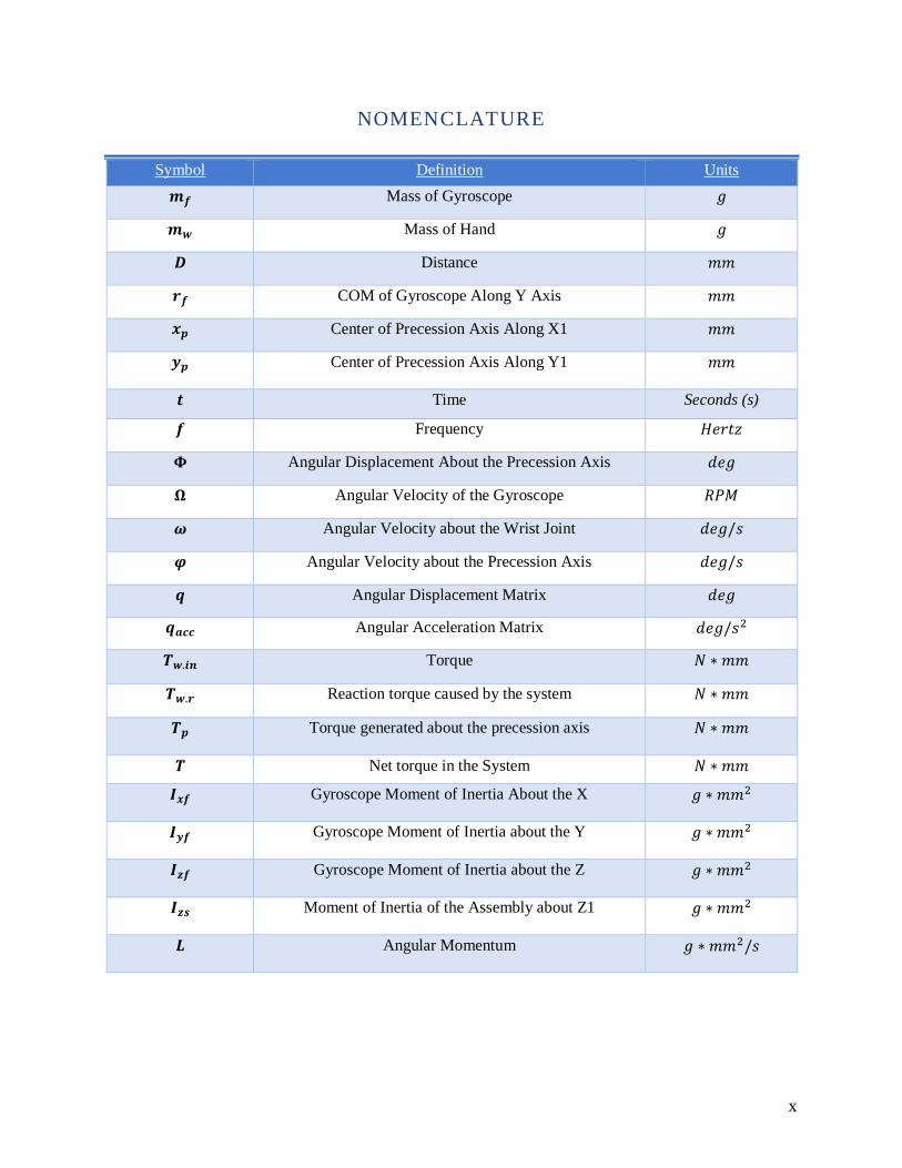
NOMENCLATURE
Symbol Definition Units
𝒎𝒇 Mass of Gyroscope 𝑔
𝒎𝒘 Mass of Hand 𝑔
𝑫 Distance 𝑚𝑚
𝒓𝒇 COM of Gyroscope Along Y Axis 𝑚𝑚
𝒙𝒑 Center of Precession Axis Along X1 𝑚𝑚
𝒚𝒑 Center of Precession Axis Along Y1 𝑚𝑚
𝒕 Time Seconds (s)
𝒇 Frequency 𝐻𝑒𝑟𝑡𝑧
𝚽 Angular Displacement About the Precession Axis 𝑑𝑒𝑔
𝛀 Angular Velocity of the Gyroscope 𝑅𝑃𝑀
𝝎 Angular Velocity about the Wrist Joint 𝑑𝑒𝑔/𝑠
𝝋 Angular Velocity about the Precession Axis 𝑑𝑒𝑔/𝑠
𝒒 Angular Displacement Matrix 𝑑𝑒𝑔
𝒒𝒂𝒄𝒄 Angular Acceleration Matrix 𝑑𝑒𝑔/𝑠2
𝑻𝒘.𝒊𝒏 Torque 𝑁 ∗ 𝑚𝑚
𝑻𝒘.𝒓 Reaction torque caused by the system 𝑁 ∗ 𝑚𝑚
𝑻𝒑 Torque generated about the precession axis 𝑁 ∗ 𝑚𝑚
𝑻 Net torque in the System 𝑁 ∗ 𝑚𝑚
𝑰𝒙𝒇 Gyroscope Moment of Inertia About the X 𝑔 ∗ 𝑚𝑚2
𝑰𝒚𝒇 Gyroscope Moment of Inertia about the Y 𝑔 ∗ 𝑚𝑚2
𝑰𝒛𝒇 Gyroscope Moment of Inertia about the Z 𝑔 ∗ 𝑚𝑚2
𝑰𝒛𝒔 Moment of Inertia of the Assembly about Z1 𝑔 ∗ 𝑚𝑚2
𝑳 Angular Momentum 𝑔 ∗ 𝑚𝑚2/𝑠
1
1.0 INTRODUCTION
Hand tremors are a condition that impact approximately 7 million people in the United
States each year and are caused by a number of underlying conditions. The severity of hand
tremors ranges from being a mild irritation to a large disability that dramatically impacts
people’s daily lives. Activities like eating, dressing, chores, etc., all become sufficiently more
difficult with the inability to keep one’s arms and hands steady. In order to improve the quality
of life for individuals with these conditions, it is imperative to find ways to reduce and eliminate
hand tremors.
Due to the fact that there are several underlying conditions that cause hand tremors, there
is no single solution that is effective. As previously stated, hand tremors can stem from many
different origins within the body. The most common of these are Parkinson’s Disease and
Essential Tremor. Parkinson’s Disease, along with other symptoms, limits the brain’s ability to
create dopamine, which in turn manifests as a tremor. Essential Tremor is a disorder that is not
yet fully understood. It has been observed to be passed down genetically and causes individuals
to have tremors in various locations and severities. The current treatments for these conditions,
such as beta-blockers for Essential Tremor and Levodopa for Parkinson’s can be effective,
however they are not permanent solutions. To help alleviate the impact of tremors, there have
been a number of devices and products made to either reduce the effect of the tremor during a
specific activity, or to reduce the tremor entirely.
These devices can be very helpful in allowing people with hand tremors complete
everyday tasks that would otherwise be difficult. Enhanced utensils make eating and cooking
easier and self-adjusting mug handles can make drinking easier. However, the issue with these

2
devices is that they are limited to the specific task they were designed for. Currently, there are
few products on the market that eliminate or reduce tremors from the hand itself. The only one
currently available is the ReadiSteadi, which uses a system of weights to reduce tremors. There
are several systems in development, such as the Steadywear, which uses earthquake dampening
technology to eliminate tremors, and the Emma watch, which counteracts tremors with a
vibration counter frequency to break the feedback loop in the brain causing tremors. Another
product in development is the Gyroglove, which uses a gyroscope mounted on top of the hand to
resist the rapid movements of tremors.
The goal of this project is to incorporate the principles of gyroscopic stability to create a
device that actively reduces the tremors experienced by the hand. Rotating objects naturally
resist motions that attempt to move them out their plane of rotation. The larger the impulse, the
larger the resistance force that the rotating object exerts. This means that while it will resist the
high frequency movements of tremors, it will allow the motion of steady, deliberate movement.
This will allow individuals to experience life without the disablement of hand tremors, and can
be universally applied to multiple tasks, rather than one specific function.
3
2.0 BACKGROUND
This chapter presents background information on hand tremors and current treatment
methods. First is an examination of different hand tremor conditions and biological factors that
go into a diagnosis. Discussed next are modern treatments for various tremors types. After,
products and orthotics are introduced to provide insight on solutions to relieve tremor symptom.
Finally, the physics behind the use of gyroscopes to reduce tremors.
2.1 TREMOR CLASSIFICATION: RESTING VS. ACTION
There are two primary classifications of tremor: resting tremor and action tremor. The
American Academy of Family Physicians defines resting tremor as occurring “... in a body part
that is relaxed and completely supported against gravity” (Crawford, 2011). Resting tremor is
diagnosed when the appendage in question is not intentionally stimulated by the individual, yet
the body part continues to tremor regardless. Resting tremor can be typically enhanced by things
like mental stress, or movement of other body parts, while deliberate actions can cause resting
tremor to temporarily subside. Resting tremor is also often referred to as “pill rolling” tremor.
This is due to the movement of the hands and fingers resembling the circular movements of
rolling small objects, such as pills, in the hands. Resting tremor is most often diagnosed in
individuals with Parkinson’s Disease (NINDS, 2017).
Action tremor is therefore defined as occurring during voluntary or deliberate movement by
the individual of a muscle or appendage. Most tremors types are considered to be classified as
action tremors and can be further separated into the following tremor subcategories, some of
which overlap.
4
• Postural tremor occurs when the individual is attempting to maintain a specific position
against the force gravity, such as holding the arms in an outstretched position.
• Kinetic tremor is connected with any deliberate movement, such as opening and closing
hands.
• Intention tremor is generated with purposeful movement towards and intended target,
such as touching the nose with a finger. In most situations, the tremor will get more
pronounced as the individual gets closer to their target.
• Task-specific tremor is generally reserved for when the individual is performing a
skilled, goal-oriented task, such as handwriting or drawing shapes.
• Isometric tremor occurs during a voluntary muscle contraction, which is not
accompanied by other movement, such as holding a weight in a still position. (NINDS,
2017)
2.2 CATEGORIES OF TREMOR TYPES
Tremors are often categorized by their appearance and where they originate from within
the body. When a physician diagnoses a patient, they take into consideration a number of
different observations to determine the nature of the tremor. The key elements include whether
the tremor is active when the muscle is at rest or contracted, the location of the tremor, and if it is
mirrored on both sides of the body. Certain tremor characteristics, such as frequency and
amplitude, are also taken into account when diagnosing a tremor. There are over twenty different
types of tremors that have been identified; the most common of which are included in this
section. It is important to note that many tremor manifestations may be similar, but they are
categorized by their root cause.
5
2.2.1 CEREBELLAR TREMOR
Cerebellar tremor can appear as many other forms of tremor, and manifests itself as a
high amplitude, low frequency tremor. This means that it is easily visible and noticeable.
Cerebellar tremor causes agitation at the end of extremities, typically at the end of an intentional
movement, such as reaching for an object (NINDS, 2017). Cerebellar tremor is a tremor that is
caused by damage to the cerebellum and its pathways to other regions of the brain. This damage
can be caused by things like heart attacks or stroke. The cerebellum is located at the base of the
skull where the brain meets the spinal cord and contributes to the coordination and precision of
muscle movements. It is not responsible for initiating movements (Britannica).
2.2.2 DYSTONIC TREMOR
Dystonic tremor is a symptom of the movement disorder dystonia. Dystonic tremor
occurs due to incorrect message transfer from the brain to the corresponding muscle, causing
them to be overactive. Dystonic tremor occurs where the dystonia is located. For example,
dystonia in the head or neck and cause the head and neck to rotate or bob back and forth.
Dystonic tremor can cause in an individual having abnormal posture or sustained and unwanted
movements. It is also more common for dystonic tremor to affect the head and neck, along with
other areas, compared to other movement disorders (Elble, 2012).
2.2.3 ESSENTIAL TREMOR
Essential tremor is one the most common movement disorders. Essential tremor primarily
affects the hands, and can expand to the head, which can cause stuttering of the voice. Both sides

6
of the body are typically affected equally, though it can be more pronounced on the individual’s
dominant side due to essential tremor being an action tremor. For many affected people, the
tremor remains mild and constant for many years (NINDS, 2017). The shaking frequency will
often decay with age, but the severity or magnitude of the tremor may increase. Individuals
affected by essential tremor will often start noticing symptoms during adolescence (10-19), or as
middle-aged adults (35-50). At this time, it is unknown what causes essential tremor. Things like
heightened stress, fever, and exhaustion can increase its severity, while meditation and small
amounts of alcohol can help decrease its severity. There is a fair amount of evidence to support a
genetic link, but researchers are currently unsure as to what the specific connection is at this time
(Burke, 2018).
2.2.4 ORTHOSTATIC TREMOR
Orthostatic tremor is a rare disorder of erratic and rapid contractions of the legs that tend
to occur when the individual is standing. These irregular movements tend to make the individual
feel imbalance and unsteady when standing still. When the individual is in a seated position or
walking, the tremor will often disappear partially or completely, depending on the severity.
Orthostatic tremor is also sometimes referred to as “shaky legs”. At this time, it is unknown
where orthostatic tremor originates within the body. Current theories presented indicated that it is
an offset of essential tremor, genetic causes, or developmental issues experienced by the
individual. However, at this time it is unclear as to where orthostatic tremor is caused, and more
research is being conducted to understand its origins (Jankovic, 2017).
7
2.2.5 PARKINSONIAN TREMOR
Unlike most other tremors, parkinsonian tremor is a resting tremor, that can affect any
part of the body, including the fingers, hands, jaw, and feet. As defined above, resting tremors
primarily affect an individual’s appendages when they are at rest. However, Parkinsonian tremor
is also very apparent in isometric and task specific situations as well. This makes common tasks
like eating soup with a spoon particularly difficult because parkinsonian tremor inhibits the
body’s ability to make the smooth and precise motions necessary to keep the spoon steady and
level. Parkinsonian tremor is also an asymmetric condition, meaning that both sides of the body
are independent of the other’s condition. Although once one side is affected, it will always
remain the more affected side (APDA).
Parkinsonian tremor is a very common side effect of the well-known Parkinson’s disease.
Parkinson’s disease is a degenerative nervous system disorder that affects the movements of the
body. Parkinson’s is most commonly caused by failed nerve cells within the brain, various
genetic mutations that can increase the risk of Parkinson’s, or to environmental contaminants,
such as exposure to damaging toxins, that can trigger its presence. Along with tremors,
Parkinson’s disease can also cause slowed movement, rigid posture, impaired balance, and
speech impediments (Mayo, 2018).
2.2.6 PHYSIOLOGIC TREMOR
Physiologic tremor is not considered to a be a disease, but merely a normal experience.
Physiologic tremor is usually for fine tremors that includes partial shaking of an appendage that
experiences rhythmic activities. Things like cutting hair and pressing a sewing pedal over time
can create a slight repetitive tremor based on those actions (NINDS, 2017). In these examples,
8
cutting hair could lead to a slight tremor of restless fingers, and depressing sewing machine pedal
may lead to a restless leg when sitting down.
2.2.7 PSYCHOGENIC TREMOR
Psychogenic tremor is not considered to be a disease, but more a side effect of other life
conditions or mental disorders, such as stress, post-traumatic stress disorder (PTSD) or
depression (NINDS, 2017). Psychogenic tremor manifests as very fine and shaking of any parts
of the body. It can appear and disappear abruptly and is much more “responsive” to external
input. For instance, it will often disappear when the individual becomes distracted or focused on
something else (Crawford, 2011).
2.3 CURRENT TREATMENTS
The nature of tremors has been studied for a long time. In that time, a broad range of
treatments have been developed. These treatment styles can be broken down into three main
categories: medication, focused ultrasound/radio waves, and surgery. Each have several options
that are designed to counteract the effects of specific conditions and have their own advantages
and disadvantages. For instance, medications can be very effective at reducing tremors, but often
come with unwanted side effects, and can run the risk of individuals developing an immunity to
them over time. Magnetic Resonance Guided Focused Ultrasound (MRGFUS) is a rapidly
developing field that has recently been implemented to treat a wide variety of tremor disorders.
Another effective new surgery is deep brain stimulation, or DBS, in which electrodes are
9
implanted inside the brain. This section will explain in greater detail the different treatment
options that are available to people with tremor disorders.
2.3.1 MEDICATIONS
Medication is often the first option doctors will prescribe. There are an abundance of
medications for each disorder, and the one selected depends on a variety of factors, such as:
effectiveness, tolerance, health risks and tremor type. Below are details about the various
medications for individuals with two of the most common tremor causing conditions: Essential
Tremor and Parkinson’s Disease.
2.3.1.1 ESSENTIAL TREMOR MEDICATIONS
Essential Tremor (ET) is the most common tremor-causing disorder, however there are
currently no specific prescription drugs for the treatment of essential tremor (IETF, 2018).
Medications are instead used are for dealing with ET symptoms. These are pre-existing
medications developed for other conditions, including seizures and convulsions. While these
medications can be effective, they share several large issues that prevent them from being
definitive solutions. The primary problems are that there is a significant lack of understanding of
how these drugs reduce tremors, and as mentioned above, patients can become resistant to the
treatments overtime. The medications are only temporary solutions to symptoms that can be
long-lasting. As of today, the two most prescribed medications fall into two forms: beta blockers
and anti-seizure medications (WebMD, 2018).
Beta blockers are generally used as the first option of medication for essential tremor. It
is speculated that beta blockers, such as propranolol (Inderal), atenolol, metoprolol, and sotalol,
10
block nerve impulses that cause the tremors (WebMD, 2018). Although the result of taking the
medication can be an improvement, this line of medication is effective in 50-60% of patients
(Neurology Reviews, 2015). Inderal is the other commonly used beta blockers, and is effective in
reducing overall tremors, though does not completely eliminate them. Studies have shown that
around 10% of patients who take Inderal for tremors stop benefiting from it after a year of
treatment. It is currently unknown why this occurs because it is still not fully understood how it
works to treat tremor yet (WebMD, 2018). People taking Inderal have also been found to be
unable to tolerate it. This is typical when the other forms of the beta blockers are used. Although
in some cases, patients do not respond to these new medications, and/or cannot tolerate their
effects either. Inderal and other beta blockers are taken once or twice a day and have relatively
minor potential side effects. These typically include drops in blood pressure, fatigue, and erectile
dysfunction. If these side-effects occur, they may also require an anti-seizure medication.
If beta blockers are rendered to be ineffective, the next level of medication for essential
tremor is primidone, or mysoline. Primidone is an anticonvulsant drug that is prescribed off-label
to treat patients with ET. Primidone is effective in approximately 60% of patients, and in some
cases can be more effective than beta-blockers. In multiple placebo-controlled trials, primidone
was proven to reduce the amplitude of upper limb tremors by 60-66%. However, the reduction of
tremors in other areas of the body were not as consistent or conclusive (Lyons, 2015). Primidone
is most effective at reducing hand tremors, though in some cases it created worse tremors for
certain individuals. It also bears the potential undesired side effects of dizziness, nausea, and
fatigue. Primidone also has the potential, although rare, to create a complication with blood cells
and bone marrow. It also runs a similar risk to beta-blockers of patients developing an immunity
to it after a year or so of treatment (WebMD, 2018).
11
2.3.1.2 PARKINSONIAN TREMOR MEDICATIONS
Unlike Essential Tremor, Parkinson’s Disease does have several medications that are
made to directly treat the underlying disease. One of the most popular prescriptions is Levodopa,
which has been in use for over 40 years. Levodopa works by entering the brain and turning into
dopamine. Parkinson’s Disease creates a deficiency of dopamine in the brain, and this lack of
dopamine is what causes the tremors to occur. By feeding Levodopa as a supplemental source of
dopamine, the tremors are then reduced. It is considered to be largely effective, especially when
dopa-decarboxylase inhibitors (DDCI) are taken in conjunction with it.
DDCI drugs, such as Cardidopa, slow Levodopa’s peripheral conversion to dopamine,
which reduces side effects and increases its half-life, allowing it to be more effective for longer
periods of time (Salat, 2013). The treatment is considered to be one of the most effective forms
of treatment, however it is not without side effects. These include: somnolence (intense
drowsiness), mood changes, nausea, hypotension, vomiting, and in rare cases worsening in their
condition and depression (Salat, 2013). Long term Levodopa treatment has been shown to
potentially lead to motor complications and dyskinesia. Despite these side effects, its
effectiveness in reducing symptoms makes it a preferable option. This may especially appeal to
young patients as they typically want to remain employable and physically active for as long as
possible (Salat, 2013).
12
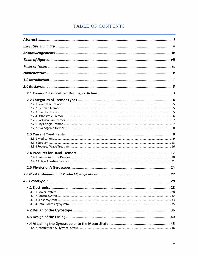
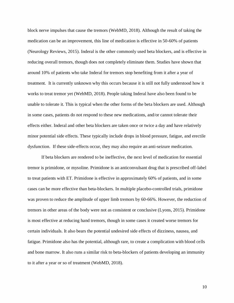
FIGURE 1: MECHANISMS OF PARKINSON’S MEDICATION IN THE BODY (BURBLLA, 2017)
Another common medication is dopamine agonists. This medication works by acting
similarly to dopamine in the brain (WebMD, 2018). This line of medication is often tried before
Levodopa, as it has a lower risk of causing the development of motor complications. However,
after 2 years, around 50% of patients that began treatment using dopamine agonists needed to
take Levodopa to supplement their treatment to achieve the same level of symptom reduction
they previously experienced with dopamine agonists (Salat, 2013).
It has also been shown in long-term follow ups that initiating treatment with dopamine
agonists does not lower patients’ risk of developing severe motor complications (Salat, 2013).
This treatment is often considered the first option for individuals who develop Parkinson’s,
especially those with early onset Parkinson’s. Individuals with early onset Parkinson’s are much
more likely to develop motor complications later in life, and so dopamine agonists, which are
considered to lower the chances of developing these complications than Levodopa, are generally
the first recommendation by a physician. However, this treatment comes with certain behavioral
13
side effects. These can include impulse control disorder and postural hypotension, which can
make it hard to remain active and employable (Salat, 2013).
2.3.1.3 BOTULINUM TOXIN
For a more general form of tremor reduction, injections of Botulinum Toxin, also known
as “Botox”, have been proven to reduce tremors for up to 3 months at a time (Niemann, 2018). It
is naturally produced by the bacteria Clostridium botulinum. Botulinum Toxin causes flaccid
paralysis in muscles by preventing the release of acetylcholine, which is the chemical released by
motor neurons to signal muscle movement (Arnon, 2001). Use of this toxin has significantly
reduced the tremors in muscles suffering due to a fault in these signals. Patients receiving this
treatment have been reported to have noticeable improvement in their tremors with limited side
effects. This is due to the fact that the treatment is not a general body medication, but a targeted
muscle treatment. However, the downside of this treatment is that the targeted and surrounding
muscles are left feeling weak. In the case of head and neck treatments, this can cause the
individual’s voice to become hoarse, and difficulty swallowing.
2.3.2 SURGERY
For tremor causing conditions, there are two main surgical procedures. They are different
in their objectives, and the conditions for which one is selected over the other. The first method,
thalamotomy, removes part of the thalamus that is causing tremors. It executes the same function
as radiofrequency ablation but comes with more risks and is considered less effective, so it is not
used as frequently anymore. The second method is deep brain stimulation (DBS). This method
14
implants electrodes in the patient's brain that send signals to correct the signals causing tremors.
This is becoming more popular as testing shows its high level of effectiveness.
2.3.2.1 THALAMOTOMY
Thalamotomy is a procedure that is being used less and less, as it is an inherently
invasive procedure which can be done with new developing technologies previously mentioned,
such as radiofrequency ablation and MRgFUS. During this procedure a probe is inserted into the
patient’s brain, and it is used to destroy targeted tissue in the thalamus that is causing tremors to
occur. This is done by either circulating liquid nitrogen in the probe or using an electrode to heat
it up and denature the defective cells. Thalamotomy can be effective at removing tremors,
however it does not help with any other symptoms from the underlying condition (Healthwise,
2017). It also comes with certain risks, such as stroke, numbness around mouth causing drooling,
seizures, impaired speech, and cognitive impairment. These serious side effects and the nature of
the procedure only fixing tremors and no other symptoms that other developed treatments can
address, are large factors into why thalamotomy is not seen in practice as frequently in modern
treatment.
2.3.2.2 DEEP BRAIN STIMULATION
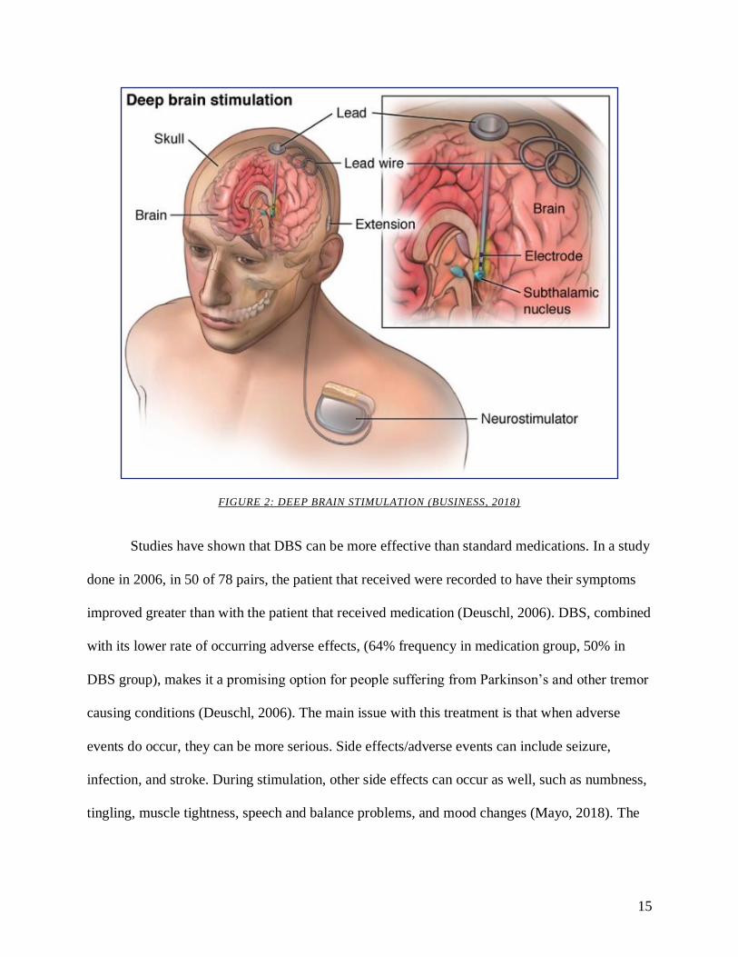
Deep brain stimulation, or DBS, is a developing treatment that uses implanted electrodes
to eliminate tremors from jumbled signals within the brain. The electrodes are connected to a
main hub that is implanted in the chest of the patient, similar to a pacemaker (Mayo, 2018).
15
FIGURE 2: DEEP BRAIN STIMULATION (BUSINESS, 2018)
Studies have shown that DBS can be more effective than standard medications. In a study
done in 2006, in 50 of 78 pairs, the patient that received were recorded to have their symptoms
improved greater than with the patient that received medication (Deuschl, 2006). DBS, combined
with its lower rate of occurring adverse effects, (64% frequency in medication group, 50% in
DBS group), makes it a promising option for people suffering from Parkinson’s and other tremor
causing conditions (Deuschl, 2006). The main issue with this treatment is that when adverse
events do occur, they can be more serious. Side effects/adverse events can include seizure,
infection, and stroke. During stimulation, other side effects can occur as well, such as numbness,
tingling, muscle tightness, speech and balance problems, and mood changes (Mayo, 2018). The
16
treatment is continuously being developed and with improvements to reduce these effects, deep
brain stimulation can be a viable option for patients with tremors.
2.3.3 FOCUSED WAVE TREATMENTS
Focused wave treatments are a developing form of treatment that is sought after as an
alternative to surgery. Both forms, Focus Ultrasound (magnetic resonance guided focused
ultrasound or MRgFUS), and Radiofrequency Ablation, use a treatment method called ablation
(Jung, 2018). Ablation is when diseased or malfunctioning tissue is purposely destroyed in order
to alleviate a condition. For example, purposely destroying faulty tissue in the heart causing
irregular electrical signals to restore proper signal transfer (Joseph, 2012). Both have seen many
positive results and are being researched and developed further to bring them more into the
mainstream of treatment.
2.3.3.1 FOCUSED ULTRASOUND
Focused ultrasound uses ultrasonic waves to destroy tissue in the ventral intermediate
(Vim), nucleus thalamus, and posterior subthalamic regions of the brain. These are the most
common areas of the brain that when dysfunctional, typically result in the manifestation of a
tremor (Jung, Na Young, 2018). The ultrasonic waves resonate the targeted parts of the thalamus,
causing heat energy to build and degenerate of proteins, cause blood to coagulate, and cell
necrosis (Jung, Na Young, 2018). Focused ultrasound also causes cavitation. Cavitation is the
formation and oscillation of microbubbles within the blood and cell cytoplasm. This in turn
damages and destroys the malfunctioning cells in the targeted area (Jung, Na Young, 2018).
17
Based on a study 2016, the results of the treatments have been largely successful. Tremor
scores across clinic decreased from a point average of 18.1 to 9.6 within three months after the
procedure. These scores also remained level after follow-up appointments held 12 months after
the surgery (Jeffery, 2016). This was said to come with an “acceptable” amount of side effects,
which included dizziness, nausea/vomiting, ataxia, and paresthesia. Despite these potential side
effects, most patients reported a favorable reduction in tremors and a “much improved daily life
and quality of living” (Jeffery, 2016).
2.3.3.2 RADIOFREQUENCY ABLATION
Radiofrequency ablation is similar to focused ultrasound in that it uses resonating
frequencies to destroy targeted tissue. This method is an adapted version of a surgery called a
thalamotomy. During the procedure, a radio frequency is sent into the brain to create an electrical
current to heat up a nerve inside the thalamus. This disrupts its ability to function for at least 6
months and alleviates the symptoms of certain conditions such as essential tremor and
Parkinson’s (Elble, 2018).
2.4 PRODUCTS FOR HAND TREMORS
This section presents a selection of products that are on the market, or currently in
development. Assistive products are categorized into two main categories: passive and active. A
passive device resists a tremor without moving parts. These designs utilize intentional design
features to aid the individual with a specific task. Active devices counteract tremors in real time.
They utilize sensory or motion input from the body to generate a counteractive response to the
18
tremor. From here, products can be further separated into tools and wearables. Tools are defined
as products that are intended for the individual to use to carry out a particular function. A
wearable refers to a product that an individual mounts or straps to their body to reduce tremors.
Wearables may also be referred to as an orthosis or orthotic, which is defined as an externally
applied device used to modify the structural and functional characteristics of the neuromuscular
and skeletal system.
2.4.1 PASSIVE ASSISTIVE DEVICES
Passive devices for hand tremors are usually an ergonomic improvement or a weighted
object designed to aid the movement of the user. One of the most challenging tasks for
individuals with hand tremors is dexterity, which is required for conducting simple, everyday
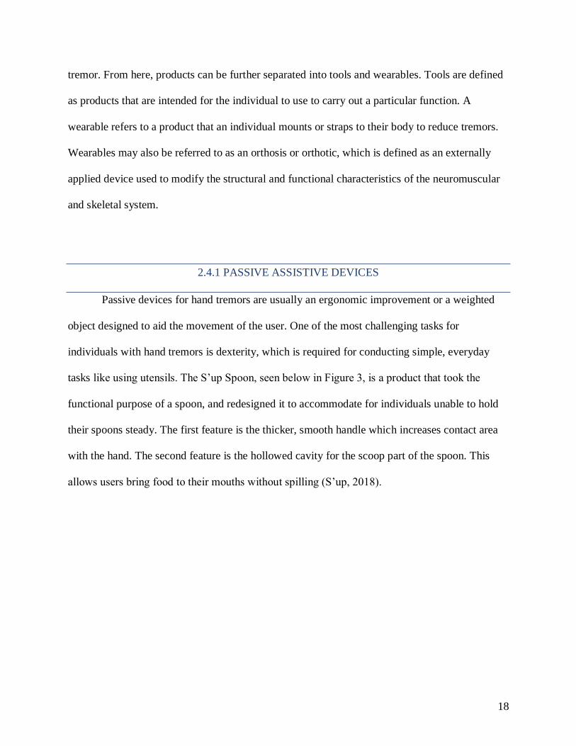
tasks like using utensils. The S’up Spoon, seen below in Figure 3, is a product that took the
functional purpose of a spoon, and redesigned it to accommodate for individuals unable to hold
their spoons steady. The first feature is the thicker, smooth handle which increases contact area
with the hand. The second feature is the hollowed cavity for the scoop part of the spoon. This
allows users bring food to their mouths without spilling (S’up, 2018).
19
FIGURE 3: S’UP SPOON BASIC DESIGN (S’UP, 2018)
Another feature is increasing the mass. The idea is that through conservation of
momentum, increasing the mass of a system will decrease the velocity. In this case, solutions
like those of Keatlery Weighted Utensils, have altered the weight of their utensils to about 8
ounces. The added weight slows hand movements, thus dampening the effects of the individual’s
tremors when eating (Keatlery Weighted Dining Utensil, 2018).
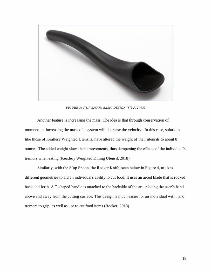
Similarly, with the S’up Spoon, the Rocker Knife, seen below in Figure 4, utilizes
different geometries to aid an individual's ability to cut food. It uses an arced blade that is rocked
back and forth. A T-shaped handle is attached to the backside of the arc, placing the user’s hand
above and away from the cutting surface. This design is much easier for an individual with hand
tremors to grip, as well as use to cut food items (Rocker, 2018).
20
FIGURE 4: ROCKER KNIFE (ROCKER, 2018)
Other eating solutions include the Eatwell Assistive Tableware Set and the Stay Bowl.
The two products utilize slip-resistant and anti-tip features to improve their stability. The
tableware set has weighted and slanted bottoms with deep cavities to naturally congregate food.
Their spoons are designed to match the contour of the bowls to ease scooping (Eatwell, 2018).
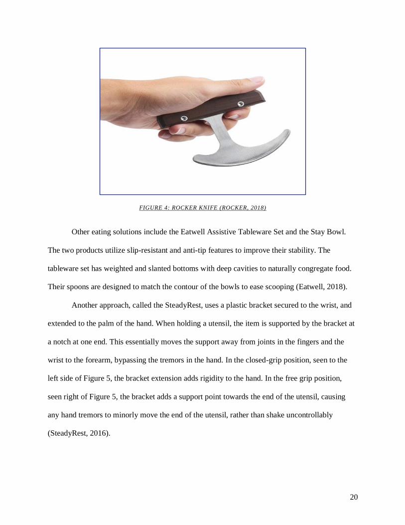
Another approach, called the SteadyRest, uses a plastic bracket secured to the wrist, and
extended to the palm of the hand. When holding a utensil, the item is supported by the bracket at
a notch at one end. This essentially moves the support away from joints in the fingers and the
wrist to the forearm, bypassing the tremors in the hand. In the closed-grip position, seen to the
left side of Figure 5, the bracket extension adds rigidity to the hand. In the free grip position,
seen right of Figure 5, the bracket adds a support point towards the end of the utensil, causing
any hand tremors to minorly move the end of the utensil, rather than shake uncontrollably
(SteadyRest, 2016).

21
FIGURE 5: STEADYREST IN THE TWO HOLDING CONFIGURATIONS (STEADYREST, 2018)
Similar to how weighted utensils dampen tremor, the Readi-Steadi is a wearable orthotic
that straps weights to the hand, wrist, and up to the elbow if desired. The Readi-Steadi system
uses custom weights to reduce undesired tremor movements. Meant to reduce mild to severe
tremors, the weights effectively reduce the magnitude of the tremor by slowing down the arm
(Readi-Steadi, 2016).
2.4.2 ACTIVE ASSISTIVE DEVICES
Active products resist or reduce tremors by producing a counter movement or force.
Products in this category contain moving parts and/or electronics that control the device’s
reaction to a tremor.
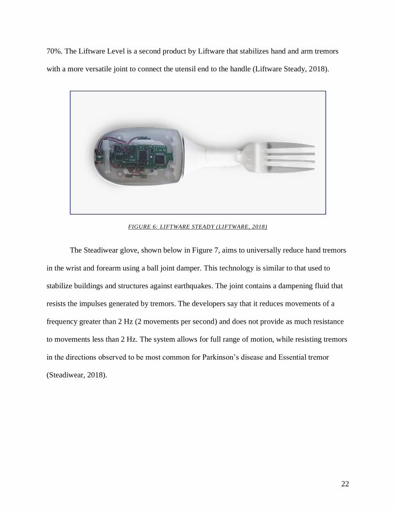
Liftware Steady is a smart modular utensil with a variety of utensil attachments for eating.
The device, seen below in Figure 6, uses active stabilization on the utensil end using advanced
sensor and motor-based cancellation technology. Sensors within the handle measure the
magnitude and direction of the motion generated and adjust the utensil end appropriately to keep
it as level as possible. The highly sophisticated system is able to reduce tremors to the utensil by
22
70%. The Liftware Level is a second product by Liftware that stabilizes hand and arm tremors
with a more versatile joint to connect the utensil end to the handle (Liftware Steady, 2018).
FIGURE 6: LIFTWARE STEADY (LIFTWARE, 2018)
The Steadiwear glove, shown below in Figure 7, aims to universally reduce hand tremors
in the wrist and forearm using a ball joint damper. This technology is similar to that used to
stabilize buildings and structures against earthquakes. The joint contains a dampening fluid that
resists the impulses generated by tremors. The developers say that it reduces movements of a
frequency greater than 2 Hz (2 movements per second) and does not provide as much resistance
to movements less than 2 Hz. The system allows for full range of motion, while resisting tremors
in the directions observed to be most common for Parkinson’s disease and Essential tremor
(Steadiwear, 2018).
23
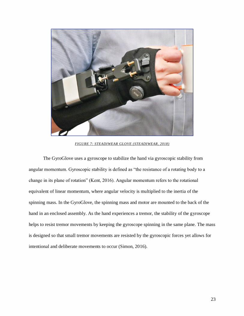
FIGURE 7: STEADIWEAR GLOVE (STEADIWEAR, 2018)
The GyroGlove uses a gyroscope to stabilize the hand via gyroscopic stability from
angular momentum. Gyroscopic stability is defined as “the resistance of a rotating body to a
change in its plane of rotation” (Kent, 2016). Angular momentum refers to the rotational
equivalent of linear momentum, where angular velocity is multiplied to the inertia of the
spinning mass. In the GyroGlove, the spinning mass and motor are mounted to the back of the
hand in an enclosed assembly. As the hand experiences a tremor, the stability of the gyroscope
helps to resist tremor movements by keeping the gyroscope spinning in the same plane. The mass
is designed so that small tremor movements are resisted by the gyroscopic forces yet allows for
intentional and deliberate movements to occur (Simon, 2016).
24
2.5 PHYSICS OF A GYROSCOPE
Gyroscopic stabilization works by responding to an input torque with an equal and
opposite reaction torque. When a torque acts on a gyroscope and attempts to move it off of its
spin axis, the spinning of the gyroscope generates another torque that acts orthogonally to this
input torque. This motion is known as precession. Precession generates an additional torque that
resists the original input torque. It is the generation of this resistance torque that is opposite and
proportional to the input torque that is the basis of the final design.
To understand the capabilities of the design, it is important to review the physics of the
system. One of the fundamental properties of how gyroscopes operate is angular momentum.
That is the product of an object’s moment of inertia and angular velocity. This is displayed in
Equation 1 below.
�̅� = 𝐼𝑔 ∗ �̅�
This equation follows Newton’s First Law; a gyroscope maintains its angular momentum
unless an external force acts upon it. This means that a gyroscope will naturally maintain its
angular velocity and by extension, its plane of rotation. In order to change the angular velocity of
the gyroscope, an external moment must be applied, as seen in Equation 2.
Σ𝑀𝑔̅̅ ̅̅ =
𝑑(𝐼𝑔 ∗ �̅�)
𝑑𝑡
The moment of inertia (I) is the tendency for a rotating object to maintain its angular
velocity based on its geometric properties. The equation for moment of inertia is shown below as
Equation 3, in which c is the geometric coefficient:
𝐼 = 𝑐 ∗ 𝑚 ∗ 𝑟2
By determining the moments of inertia, the acting torques in the system can be
calculated. This is because torque is equal to the change in angular momentum with respect to

25
time. This relationship can be seen below as Equation 4, which is derived by simplifying
Equation 2 by replacing the moment variable (mg) with torque (𝜏) and converting the moment of
inertia and angular velocity to the change in angular momentum.
�̅� = ∆(𝑐 ∗ 𝑚𝑔 ∗ 𝑟2 ∗ 𝑎)
∆𝑡
To determine the direction and magnitude of the output torque in the gyroscopic system,
the team adapted a model developed by Brendon Allen at Brigham Young University. Allen
conducted analyses on different gyroscope configurations to determine a theoretical optimal
design of a gyroscopic tremor suppression device. The basis of his model is shown in Equation 5,
(Allen, 2018).
𝐻 ∗ 𝑞𝑎𝑐𝑐 + 𝐶 = 𝐹
In this equation, H represents the moments of inertia of the gyroscope about different
axes. The qacc signifies the angular acceleration of the hand caused by the tremor and the
gyroscope due to the subsequent precession. Multiplied together, H*qacc equals the torques
caused by the motion of the hand. C represents the torques created by the movement of the
system. The resultant torques about the axis of rotation and precession axis are represented by F.
The expanded version of the H and C components are shown here:
26
The variables were determined based on a combination of research, hand calculations,
and Solidworks analysis based on the final design. A study by Calzetti et al. measured these
values for Essential Tremor, one of the most common forms of tremor that act about a central
oscillator, in the form of displacement from the vertical plane. The average and extreme angular
displacement of the hand is 3.2 and 32 degrees respectfully. The frequency range is from 3-6
hertz (Calzetti, 1987). This value was then used to determine the angular velocity of the hand.
Angular displacement of the tremor is divided by its corresponding frequency, shown in
Equation 6.
𝜔 =𝜃
𝑓
For the angular acceleration of the hand, rather than finding the average acceleration by
using the change in velocity over time, the team solved for the hand’s instantaneous acceleration.
This is more accurate to the motions occurring in a real tremor given the nature of a tremor to
cause sudden small movements. Rearranging Equation 1 solves for the acceleration based on the
input torque, Τw.in, shown as Equation 7.
𝑞(𝜃) =𝑇𝑤.𝑖𝑛
𝐼𝑧𝑠
A similar reconfiguration of Equation 1 solves the angular velocity of the gyroscope as it
is rotated about the precession axis, shown below as Equation 8.
𝜑 =𝑇𝑤.𝑖𝑛
𝐼𝑦𝑓 ∗ Ω

27
3.0 GOAL STATEMENT AND PRODUCT SPECIFICATIONS
The goal of this project was to create an assistive system that uses a gyroscope to
stabilize hand tremors for use in multiple applications. Listed below are the design goal
specifications set by the team at the start of this project.
• Hand Mount:
o Weigh under 1 lb. (453.6 grams)
o Allow for full flexible wrist movement
• Sound:
o Under 80 decibels from 6 inches away
• Dimensions:
o Height: Under 50 mm - Aim to keep the height as short as possible.
o Length: Under 70mm - Contained between the knuckles and the wrist
o Width: Under 70 mm - Contained between the pinky and forefingers knuckles on
the average female's hand,
• Effectiveness:
o Reduce hand tremor magnitude by 70%
• Sensors
o Successfully identify “hand tremor” patterns

28
4.0 PROTOTYPE 1
This chapter describes the design of the team’s first prototype. The pages below describe
the design ideas behind each aspect of the design, including how it is powered, controlled,
assembled, and shaped.
4.1 ELECTRONICS
This section discusses all of the electronic systems and components used to control and
power the gyroscope. The different subsystems are broken down into power, control, sensory,
and data processing.
4.1.1 POWER SYSTEM
The role of the power system is to supply energy to the motor to spin the gyroscope. The
power system is essential in creating the rotation needed to counteract the torque generated by
hand tremors. The three components of the power system are: the power supply, the speed
controller, and the motor. Each component was carefully selected using a decision matrix to
compare competing products, and to ensure compatibility to avoid damaging other components.
The motor is the primary component that underwent an arduous selection process. The
team began with selecting the motor before anything else, as it would influence other aspects of
the system. Factors such as motor type, size, revolutions per minute per volt (kV) all affect the
performance of the motor. The decision was first made to select a brushless motor instead of a
brushed motor type. Brushless motors have significant advantages over brushed which include
higher efficiency, longer lifespan, and little to no maintenance. They do not have components
29
that contact each other during rotation, whereas brushed motors use brushes inside the motor that
can wear and create friction, and therefore heat. The team went to scout for brushless motors in
online hobbyist drone markets. With the rise of the drone industry in the past few years, the
abundance and competition of the motors in the drone market provided a wide variety of options.
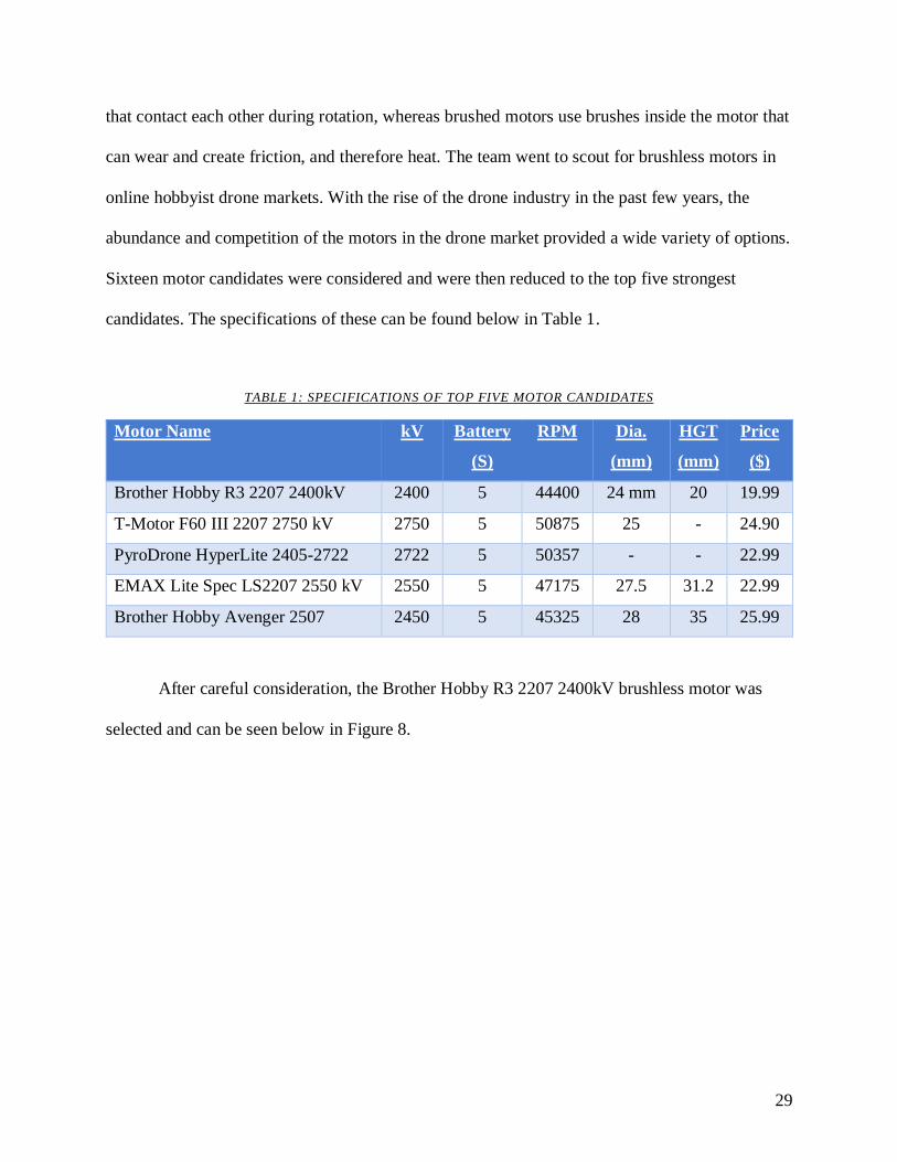
Sixteen motor candidates were considered and were then reduced to the top five strongest
candidates. The specifications of these can be found below in Table 1.
TABLE 1: SPECIFICATIONS OF TOP FIVE MOTOR CANDIDATES
Motor Name kV Battery
(S)
RPM Dia.
(mm)
HGT
(mm)
Price
($)
Brother Hobby R3 2207 2400kV 2400 5 44400 24 mm 20 19.99
T-Motor F60 III 2207 2750 kV 2750 5 50875 25 - 24.90
PyroDrone HyperLite 2405-2722 2722 5 50357 - - 22.99
EMAX Lite Spec LS2207 2550 kV 2550 5 47175 27.5 31.2 22.99
Brother Hobby Avenger 2507 2450 5 45325 28 35 25.99
After careful consideration, the Brother Hobby R3 2207 2400kV brushless motor was
selected and can be seen below in Figure 8.
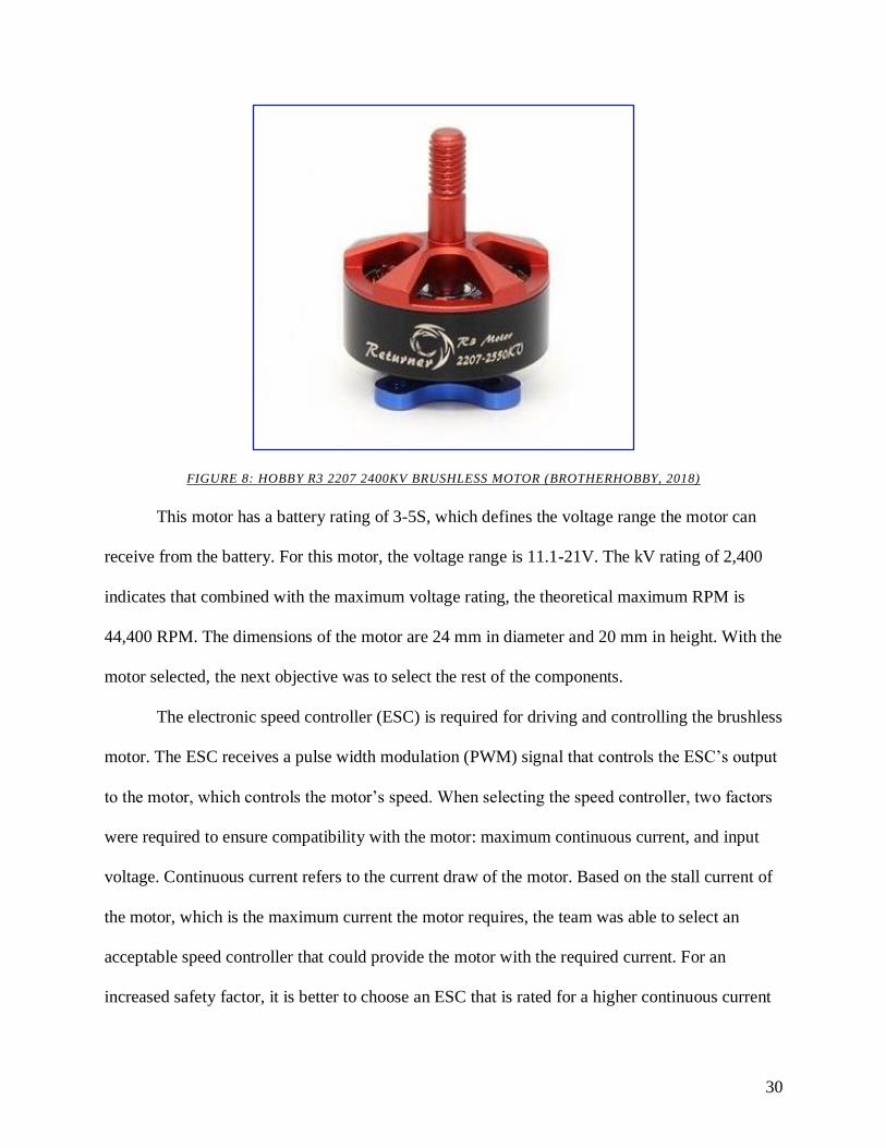
30
FIGURE 8: HOBBY R3 2207 2400KV BRUSHLESS MOTOR (BROTHERHOBBY, 2018)
This motor has a battery rating of 3-5S, which defines the voltage range the motor can
receive from the battery. For this motor, the voltage range is 11.1-21V. The kV rating of 2,400
indicates that combined with the maximum voltage rating, the theoretical maximum RPM is
44,400 RPM. The dimensions of the motor are 24 mm in diameter and 20 mm in height. With the
motor selected, the next objective was to select the rest of the components.
The electronic speed controller (ESC) is required for driving and controlling the brushless
motor. The ESC receives a pulse width modulation (PWM) signal that controls the ESC’s output
to the motor, which controls the motor’s speed. When selecting the speed controller, two factors
were required to ensure compatibility with the motor: maximum continuous current, and input
voltage. Continuous current refers to the current draw of the motor. Based on the stall current of
the motor, which is the maximum current the motor requires, the team was able to select an
acceptable speed controller that could provide the motor with the required current. For an
increased safety factor, it is better to choose an ESC that is rated for a higher continuous current
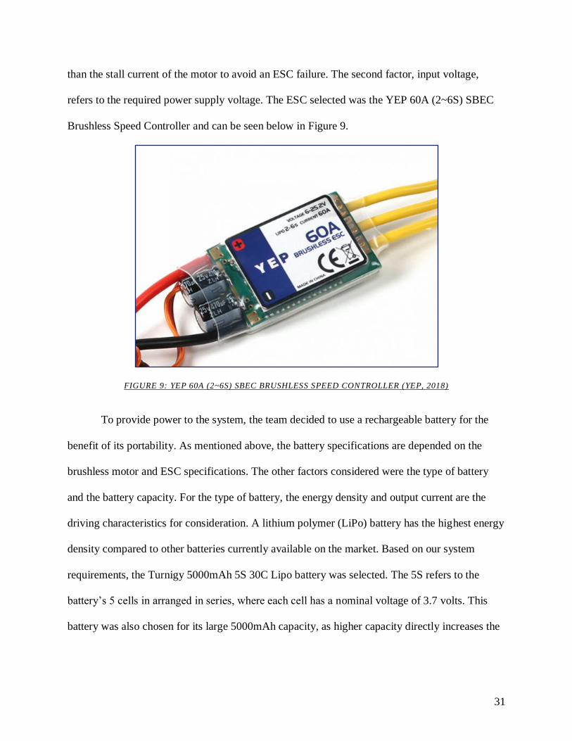
31
than the stall current of the motor to avoid an ESC failure. The second factor, input voltage,
refers to the required power supply voltage. The ESC selected was the YEP 60A (2~6S) SBEC
Brushless Speed Controller and can be seen below in Figure 9.
FIGURE 9: YEP 60A (2~6S) SBEC BRUSHLESS SPEED CONTROLLER (YEP, 2018)
To provide power to the system, the team decided to use a rechargeable battery for the
benefit of its portability. As mentioned above, the battery specifications are depended on the
brushless motor and ESC specifications. The other factors considered were the type of battery
and the battery capacity. For the type of battery, the energy density and output current are the
driving characteristics for consideration. A lithium polymer (LiPo) battery has the highest energy
density compared to other batteries currently available on the market. Based on our system
requirements, the Turnigy 5000mAh 5S 30C Lipo battery was selected. The 5S refers to the
battery’s 5 cells in arranged in series, where each cell has a nominal voltage of 3.7 volts. This
battery was also chosen for its large 5000mAh capacity, as higher capacity directly increases the
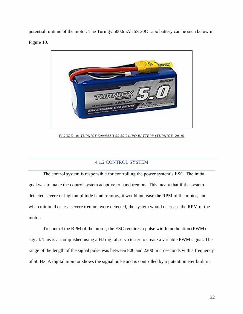
32
potential runtime of the motor. The Turnigy 5000mAh 5S 30C Lipo battery can be seen below in
Figure 10.
FIGURE 10: TURNIGY 5000MAH 5S 30C LIPO BATTERY (TURNIGY, 2018)
4.1.2 CONTROL SYSTEM
The control system is responsible for controlling the power system’s ESC. The initial
goal was to make the control system adaptive to hand tremors. This meant that if the system
detected severe or high amplitude hand tremors, it would increase the RPM of the motor, and
when minimal or less severe tremors were detected, the system would decrease the RPM of the
motor.
To control the RPM of the motor, the ESC requires a pulse width modulation (PWM)
signal. This is accomplished using a HJ digital servo tester to create a variable PWM signal. The
range of the length of the signal pulse was between 800 and 2200 microseconds with a frequency
of 50 Hz. A digital monitor shows the signal pulse and is controlled by a potentiometer built in.
33
4.1.3 SENSOR SYSTEM
To create an adaptive control system, sensors are required to provide input data. As
mentioned above, an Arduino microcontroller was used to interface with the sensors. Listed
below are the sensors that were selected for this project and their capabilities.
Gyroscopic stability is generated through the angular velocity and moment of inertia of
the gyroscope. However, the moment of inertia remains constant, whereas the RPM of the disk
can be manipulated. Three main types of tachometers to measure the RPM of a spinning object
were found currently available on the market: mechanical, optical, and stroboscopic. The optical
tachometer, which uses an infrared (IR) emitter and receiver unit wired to an integrated chip, was
selected for the purposes of this project. For the IR sensor to detect speed, a reflective tape or
surface is required over a portion of the rotating surface. When the emitter produces an IR signal,
the tape reflects the signal to be read by the receiver. Each time a reading is made, one revolution
has passed.
Hand tremors are motions that are rotating about the center of the hand. An inertial
measurement unit (IMU) was used to effectively measure that motion. An IMU contains a micro-
electromechanical system (MEMS) accelerometer and gyroscope transducer to measure
translational and rotational motion. There are many factors to consider when selecting a
transducer relevant to measuring hand tremors. The primary factors are axis, range, and
resolution. The axial parameter refers to the number of directions in which translational and
angular acceleration can be measured. Range refers to the upper and lower limits of what each
sensor can measure. For the purposes of this project, the average frequency for hand tremors
occur at 3Hz or greater (Elble, 2016). Resolution refers to the detail of a measurement when

34
converting an analog voltage to a digital value. For this project, the six axis MPU 6050 was
selected. It has a range of +/16g on the accelerometer and +/- 2000 deg./sec on the gyroscope.
It is also important to mention because the motor speed also depends on the input voltage
of the power source, a voltage sensor was connected to the battery. This measures the battery
voltage and informs the system on the capacity of the battery in real time
Figure 11 below shows the wiring diagram for the sensor system. The microcontroller is
the Arduino in the center left. The voltage sensor is in the top left of the diagram. The RPM
sensor is in the top right corner of the diagram. Finally, the MPU 6050 accelerometer and
gyroscope is in the right side of the diagram. The voltage is measured by the Arduino in the
analog input using the yellow wire. The RPM sensor is powered from the 5-volt rail and
connected to ground. The digital signal is connected by the white wire to digital input (DI) 2
which is uses the timer interrupt on the Arduino. The MPU 6050 utilized the 3.3V rail to power
the chip and is connected to ground. The purple wire connects SCL on the MPU 6050 to the
analog in (AI) port 5 and the orange wire connects SDA to AI port 4. The blue wire connects
INT to DI 3. The pink wire is connected to the ESC, which is not shown for PWM control of the
motor.
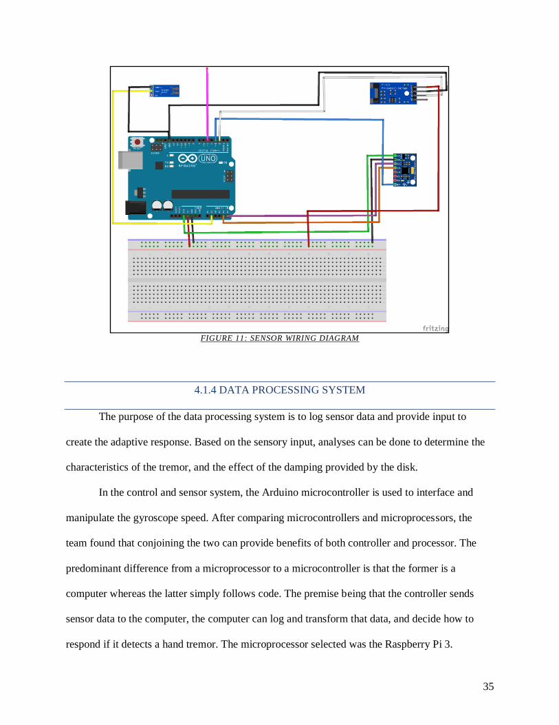
35
FIGURE 11: SENSOR WIRING DIAGRAM
4.1.4 DATA PROCESSING SYSTEM
The purpose of the data processing system is to log sensor data and provide input to
create the adaptive response. Based on the sensory input, analyses can be done to determine the
characteristics of the tremor, and the effect of the damping provided by the disk.
In the control and sensor system, the Arduino microcontroller is used to interface and
manipulate the gyroscope speed. After comparing microcontrollers and microprocessors, the
team found that conjoining the two can provide benefits of both controller and processor. The
predominant difference from a microprocessor to a microcontroller is that the former is a
computer whereas the latter simply follows code. The premise being that the controller sends
sensor data to the computer, the computer can log and transform that data, and decide how to
respond if it detects a hand tremor. The microprocessor selected was the Raspberry Pi 3.
36
The idea is to filter data from the accelerometer and gyroscope using a Fast Fourier
Transform (FFT). Fourier’s theorem states that almost any continuous sinusoidal signal can be
represented by weighted sum of sines and cosines. Since tremor is an oscillatory motion that is
roughly sinusoidal, the tremor can be mathematically decomposed into sine and cosine waves. A
plot can then be created featuring amplitude as a function of frequency, creating an amplitude
frequency spectrum. In this spectrum, the frequency and amplitude of the tremor can be
computed, and the program can automatically draw conclusions from that information.
4.2 DESIGN OF THE GYROSCOPE
Another part of the system to design was the gyroscope itself. This component is very
important, because its properties determine many factors of the final design such as weight,
comfort, noise, and effectiveness. In order for the device to be effective, the gyroscope had to
have a large enough moment of inertia so that it could generate a stabilization force. However, it
had to be as small and lightweight as possible as to minimize its bulkiness and weight. Special
consideration was needed when the gyroscope was being manufactured as well. Due to the high
operating RPMs, small deformities in the gyroscope could cause the gyroscope to oscillate at a
high frequency. This could create prominent vibrations that make the device loud,
uncomfortable, and less effective.
The design of the gyroscope uses the principles of moments of inertia to maximize its
angular momentum while being as small and lightweight as possible. The moment of inertia of
an object is determined by its shape and mass, as discussed earlier in Section 2.5. Figure 12
shows the geometric constants, c, for various geometries as they spin on a central axis. In order
to maximize the moment of inertia while keeping the weight to a minimum, the team designed
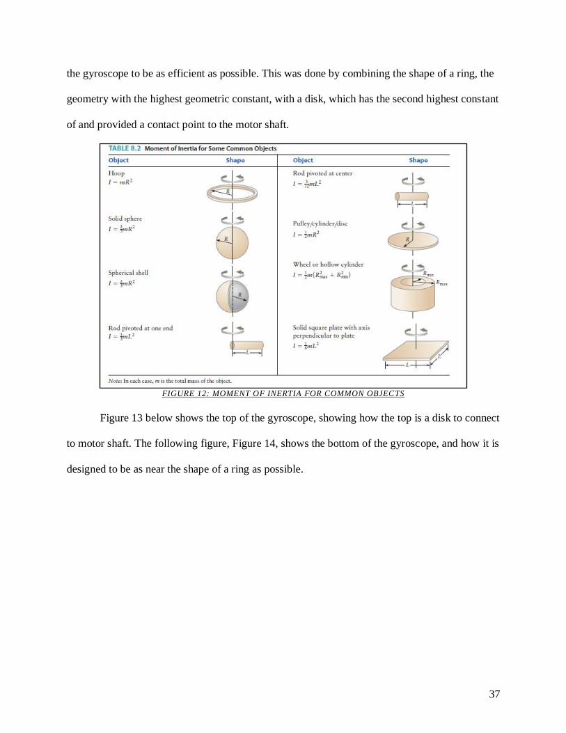
37
the gyroscope to be as efficient as possible. This was done by combining the shape of a ring, the
geometry with the highest geometric constant, with a disk, which has the second highest constant
of and provided a contact point to the motor shaft.
FIGURE 12: MOMENT OF INERTIA FOR COMMON OBJECTS
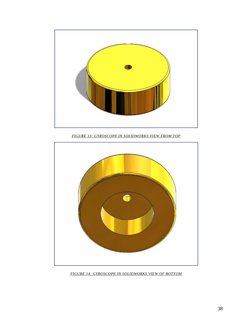
Figure 13 below shows the top of the gyroscope, showing how the top is a disk to connect
to motor shaft. The following figure, Figure 14, shows the bottom of the gyroscope, and how it is
designed to be as near the shape of a ring as possible.
38
FIGURE 13: GYROSCOPE IN SOLIDWORKS VIEW FROM TOP
FIGURE 14: GYROSCOPE IN SOLIDWORKS VIEW OF BOTTOM
39
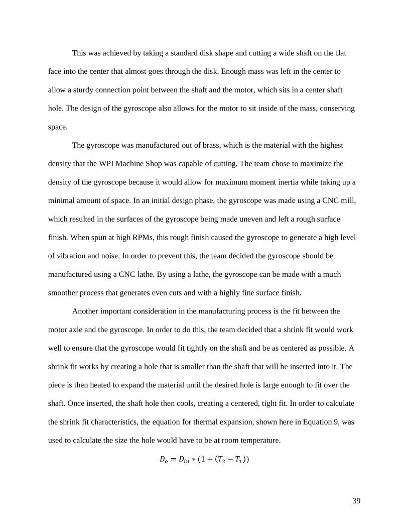
This was achieved by taking a standard disk shape and cutting a wide shaft on the flat
face into the center that almost goes through the disk. Enough mass was left in the center to
allow a sturdy connection point between the shaft and the motor, which sits in a center shaft
hole. The design of the gyroscope also allows for the motor to sit inside of the mass, conserving
space.
The gyroscope was manufactured out of brass, which is the material with the highest
density that the WPI Machine Shop was capable of cutting. The team chose to maximize the
density of the gyroscope because it would allow for maximum moment inertia while taking up a
minimal amount of space. In an initial design phase, the gyroscope was made using a CNC mill,
which resulted in the surfaces of the gyroscope being made uneven and left a rough surface
finish. When spun at high RPMs, this rough finish caused the gyroscope to generate a high level
of vibration and noise. In order to prevent this, the team decided the gyroscope should be
manufactured using a CNC lathe. By using a lathe, the gyroscope can be made with a much
smoother process that generates even cuts and with a highly fine surface finish.
Another important consideration in the manufacturing process is the fit between the
motor axle and the gyroscope. In order to do this, the team decided that a shrink fit would work
well to ensure that the gyroscope would fit tightly on the shaft and be as centered as possible. A
shrink fit works by creating a hole that is smaller than the shaft that will be inserted into it. The
piece is then heated to expand the material until the desired hole is large enough to fit over the
shaft. Once inserted, the shaft hole then cools, creating a centered, tight fit. In order to calculate
the shrink fit characteristics, the equation for thermal expansion, shown here in Equation 9, was
used to calculate the size the hole would have to be at room temperature.
𝐷𝑜 = 𝐷𝑖𝑛 ∗ (1 + (𝑇2 − 𝑇1))
40
After taking measurements with a micrometer we determined the shaft of the motor to be
4.953 mm. A MathCAD file was coded to determine the size the hole needed to be in order to
create a proper shrink fit. These calculations can be seen in Appendix A. During the calculations,
the team also took into account the various tolerances of the tools that were used to make
measurements, as well as of the manufacturing tools themselves. This is highly important
considering the size of the dimensions involved. With these calculations, it was determined that
the shaft hole needed to be 4.93 mm. In order to achieve such an exact hole size, a custom
carbide reaming tool was ordered from Walter Titek. A reamer is a tool that can be used to create
an accurate hole size after an undersized initial hole is drilled out. The reamer is capable of
creating a hole that is toleranced to +.0004mm of 4.93. Given the various tolerances, a 4.93mm
reamer would create a hole that would expand to be + .0012 mm in the best case and -.0008mm,
in the worst case, which was determined to be acceptable as that level of interference fits into the
“sliding fit” category so the shaft would still fit.
4.3 DESIGN OF THE CASING
The functionality of the casing is to act as a way to house the vital components in an
enclosed body, and to secure the mechanism to the individual’s hand. The team first began our
designing of a casing with a set of functional requirements that the case had to meet. Firstly, the
case had to be a rigid structure to house all of the necessary components that would be located on
the hand. This included the gyroscope, motor, and various electrical sensors and components.
The case had to appropriately fit on top of the hand. The team wanted to make the case large
enough to house the necessary components, but to not make it bulky so that it would be
cumbersome and unnecessarily large. Based from measurements of the team’s own hands, it was
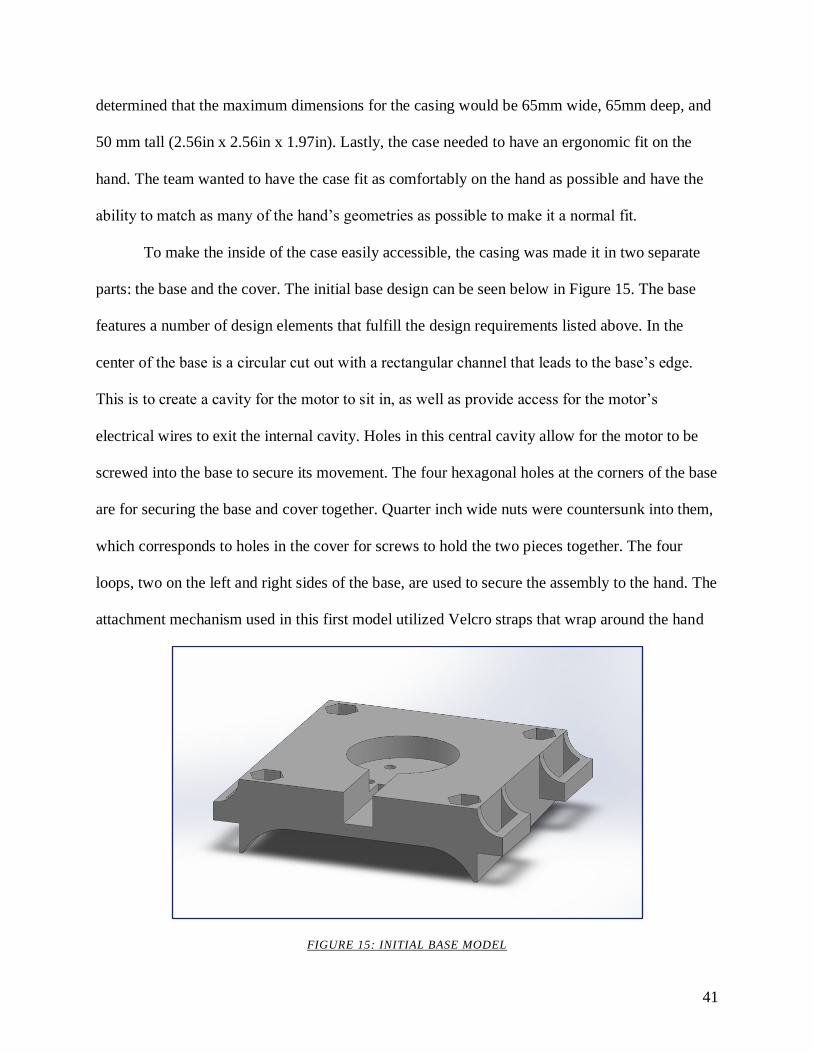
41
determined that the maximum dimensions for the casing would be 65mm wide, 65mm deep, and
50 mm tall (2.56in x 2.56in x 1.97in). Lastly, the case needed to have an ergonomic fit on the
hand. The team wanted to have the case fit as comfortably on the hand as possible and have the
ability to match as many of the hand’s geometries as possible to make it a normal fit.
To make the inside of the case easily accessible, the casing was made it in two separate
parts: the base and the cover. The initial base design can be seen below in Figure 15. The base
features a number of design elements that fulfill the design requirements listed above. In the
center of the base is a circular cut out with a rectangular channel that leads to the base’s edge.
This is to create a cavity for the motor to sit in, as well as provide access for the motor’s
electrical wires to exit the internal cavity. Holes in this central cavity allow for the motor to be
screwed into the base to secure its movement. The four hexagonal holes at the corners of the base
are for securing the base and cover together. Quarter inch wide nuts were countersunk into them,
which corresponds to holes in the cover for screws to hold the two pieces together. The four
loops, two on the left and right sides of the base, are used to secure the assembly to the hand. The
attachment mechanism used in this first model utilized Velcro straps that wrap around the hand
FIGURE 15: INITIAL BASE MODEL
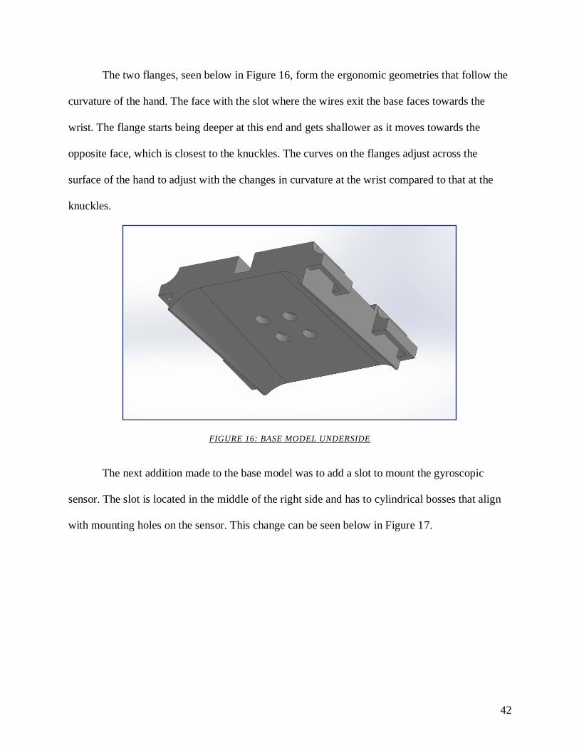
42
The two flanges, seen below in Figure 16, form the ergonomic geometries that follow the
curvature of the hand. The face with the slot where the wires exit the base faces towards the
wrist. The flange starts being deeper at this end and gets shallower as it moves towards the
opposite face, which is closest to the knuckles. The curves on the flanges adjust across the
surface of the hand to adjust with the changes in curvature at the wrist compared to that at the
knuckles.
FIGURE 16: BASE MODEL UNDERSIDE
The next addition made to the base model was to add a slot to mount the gyroscopic
sensor. The slot is located in the middle of the right side and has to cylindrical bosses that align
with mounting holes on the sensor. This change can be seen below in Figure 17.
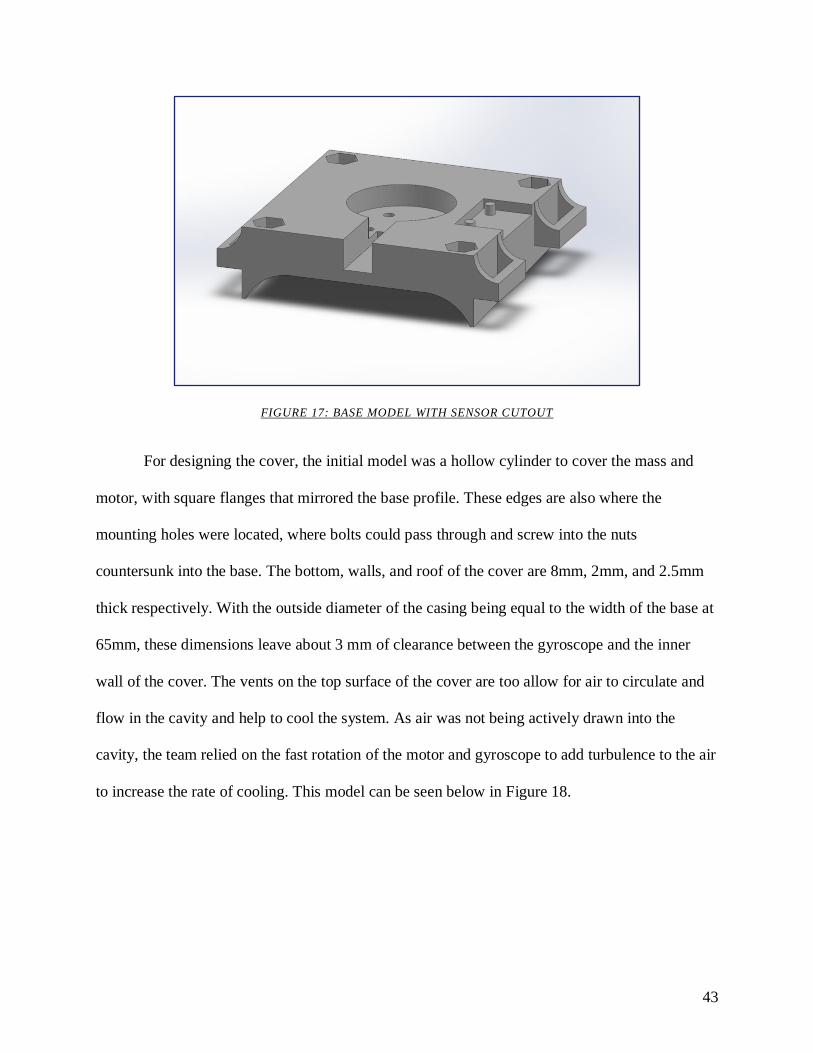
43
FIGURE 17: BASE MODEL WITH SENSOR CUTOUT
For designing the cover, the initial model was a hollow cylinder to cover the mass and
motor, with square flanges that mirrored the base profile. These edges are also where the
mounting holes were located, where bolts could pass through and screw into the nuts
countersunk into the base. The bottom, walls, and roof of the cover are 8mm, 2mm, and 2.5mm
thick respectively. With the outside diameter of the casing being equal to the width of the base at
65mm, these dimensions leave about 3 mm of clearance between the gyroscope and the inner
wall of the cover. The vents on the top surface of the cover are too allow for air to circulate and
flow in the cavity and help to cool the system. As air was not being actively drawn into the
cavity, the team relied on the fast rotation of the motor and gyroscope to add turbulence to the air
to increase the rate of cooling. This model can be seen below in Figure 18.

44
FIGURE 18: INITIAL COVER MODEL
Similar to the base, some adjustments had to be made to the cover to accommodate an
infrared RPM sensor. The sensor came mounted on a small 32mm x 14mm electrical chip, with
the sensor mounted at one end. When attempting to mount the chip to the cover, there was no
good orientation that would securely hold the chip in place without adding a large geometric
feature. The solution was to snip the connections from the chip to the infrared emitter and
receiver, which was contained within a 5.64mm x 10.14mm x 9.76mm casing. This was a much
more manageable size to mount to the motor. As seen below in Figure 19 below, the small sensor
end can easily fit onto the side of the cover, without creating any extensive geometries.
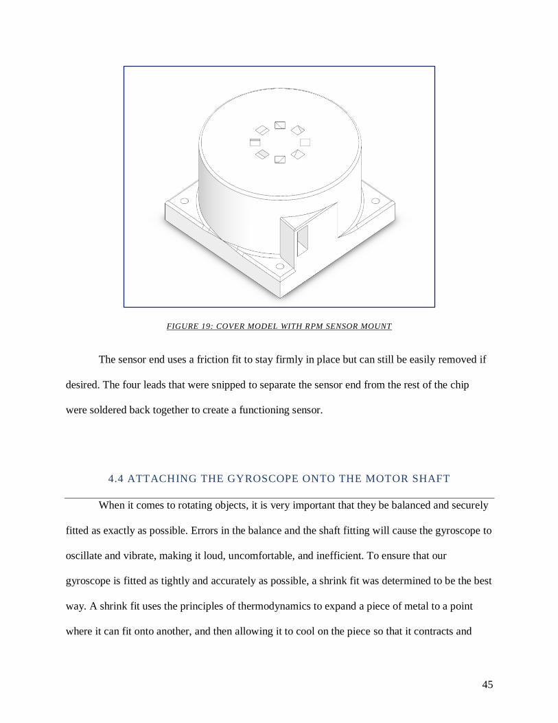
45
FIGURE 19: COVER MODEL WITH RPM SENSOR MOUNT
The sensor end uses a friction fit to stay firmly in place but can still be easily removed if
desired. The four leads that were snipped to separate the sensor end from the rest of the chip
were soldered back together to create a functioning sensor.
4.4 ATTACHING THE GYROSCOPE ONTO THE MOTOR SHAFT
When it comes to rotating objects, it is very important that they be balanced and securely
fitted as exactly as possible. Errors in the balance and the shaft fitting will cause the gyroscope to
oscillate and vibrate, making it loud, uncomfortable, and inefficient. To ensure that our
gyroscope is fitted as tightly and accurately as possible, a shrink fit was determined to be the best
way. A shrink fit uses the principles of thermodynamics to expand a piece of metal to a point
where it can fit onto another, and then allowing it to cool on the piece so that it contracts and
46
creates an exact, tight fit. In order to do this, we did calculations on the thermal expansion of
gyroscope with various shaft hole sizes based off of our motors shaft.
4.4.2 INTERFERENCE & FLYWHEEL STRESS
The team calculated the stress based off the shrink fit characteristics. For this calculation,
the worst-case tolerance scenario used the maximum shaft diameter and the minimum bore
diameter. As shown in the calculations in Appendix B, the interface pressure between the shaft
and the bore in the disk was found to be 0.172MPA. From there, the stress of the bore on the disk
and the shaft stress could be calculated. The bore stress is 337 MPa and the shaft stress is 0.172
MPa. This does not exceed the ultimate tensile nor the yield strength of the brass. The strain of
the shaft was calculated and considered to be insignificant, whereas the strain on the bore was
calculated to be about 0.008mm.
To ensure the brass disk did not fail under high rotation, the tensile stress of the outer rim
was calculated using the density of the brass, the radius of the disk, and the maximum RPM of
the motor. The tensile stress at the outside of the disk is 135 MPa. See Appendix B for full
calculations.
47
5.0 FINAL PROTOTYPE
This chapter describes the final design after testing on the preliminary model was
conducted. Each of the following subsections describe the main design iterations and
adjustments each component underwent. At the end of this section, there will be a summary of
the prototype in its final state.
5.1 CRADLE
The most important component that was added to the design is the cradle. The cradle is a
component that rotates within the base and allows the gyroscope to precess. Initially, the cradle
was designed as a simple swing with two support pillars. At the top of each of the pillar’s holes
were created to connect to rotating pins to allow the cradle to swing with the gyroscope’s
precession. The teamed then placed holes located in the center of the cradle to allow the motor to
be mounted to the system by screws through the bottom. In this arrangement, the holes are
aligned such that the wires for the motor exit out of the front of the cradle through the small
rectangular channel. This can be seen in Figure 20 shown below.
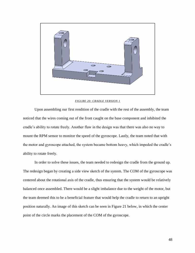
48
FIGURE 20: CRADLE VERSION 1
Upon assembling our first rendition of the cradle with the rest of the assembly, the team
noticed that the wires coming out of the front caught on the base component and inhibited the
cradle’s ability to rotate freely. Another flaw in the design was that there was also no way to
mount the RPM sensor to monitor the speed of the gyroscope. Lastly, the team noted that with
the motor and gyroscope attached, the system became bottom heavy, which impeded the cradle’s
ability to rotate freely.
In order to solve these issues, the team needed to redesign the cradle from the ground up.
The redesign began by creating a side view sketch of the system. The COM of the gyroscope was
centered about the rotational axis of the cradle, thus ensuring that the system would be relatively
balanced once assembled. There would be a slight imbalance due to the weight of the motor, but
the team deemed this to be a beneficial feature that would help the cradle to return to an upright
position naturally. An image of this sketch can be seen in Figure 21 below, in which the center
point of the circle marks the placement of the COM of the gyroscope.
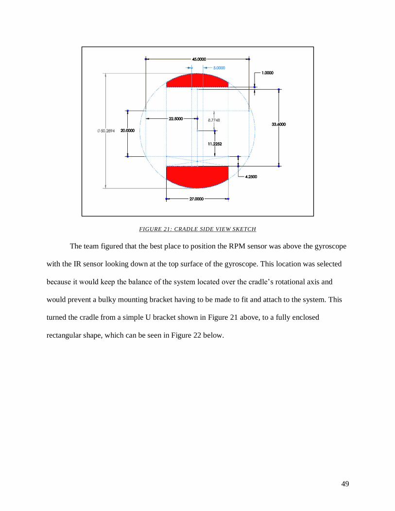
49
FIGURE 21: CRADLE SIDE VIEW SKETCH
The team figured that the best place to position the RPM sensor was above the gyroscope
with the IR sensor looking down at the top surface of the gyroscope. This location was selected
because it would keep the balance of the system located over the cradle’s rotational axis and
would prevent a bulky mounting bracket having to be made to fit and attach to the system. This
turned the cradle from a simple U bracket shown in Figure 21 above, to a fully enclosed
rectangular shape, which can be seen in Figure 22 below.
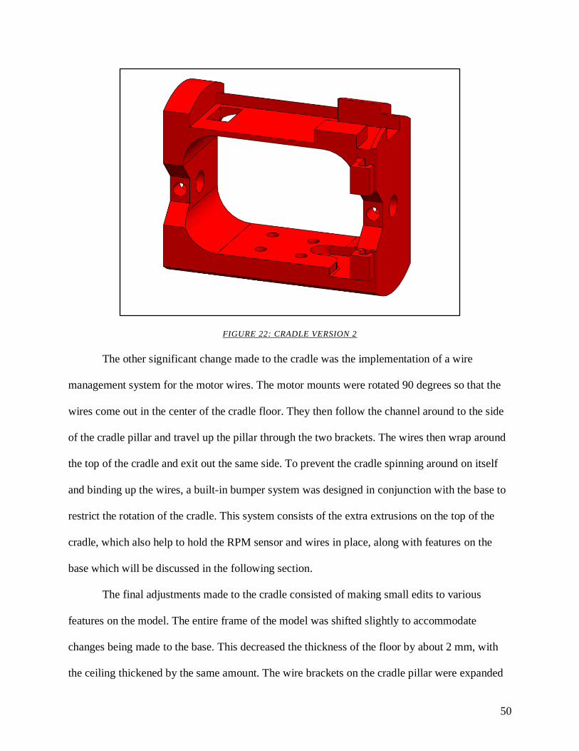
50
FIGURE 22: CRADLE VERSION 2
The other significant change made to the cradle was the implementation of a wire
management system for the motor wires. The motor mounts were rotated 90 degrees so that the
wires come out in the center of the cradle floor. They then follow the channel around to the side
of the cradle pillar and travel up the pillar through the two brackets. The wires then wrap around
the top of the cradle and exit out the same side. To prevent the cradle spinning around on itself
and binding up the wires, a built-in bumper system was designed in conjunction with the base to
restrict the rotation of the cradle. This system consists of the extra extrusions on the top of the
cradle, which also help to hold the RPM sensor and wires in place, along with features on the
base which will be discussed in the following section.
The final adjustments made to the cradle consisted of making small edits to various
features on the model. The entire frame of the model was shifted slightly to accommodate
changes being made to the base. This decreased the thickness of the floor by about 2 mm, with
the ceiling thickened by the same amount. The wire brackets on the cradle pillar were expanded

51
to allow for the motor wires to pack in more easily, as the previous ones were not wide enough.
The final model of the cradle can be seen in Figure 23 below.
FIGURE 23: CRADLE FINAL VERSION
5.2 BASE
With the introduction of the cradle, the base also had to go through a series of design
changes as well. We started by adding posts to the left and right sides of the wearer’s hand to
hold the cradle. The posts had spaces placed in the sides to hold a set of ball bearings in place via
a press a fit. The ball bearings selected had an outer diameter of 0.625 inches, purchased from
McMaster Carr (Item #: 60355K503). For each of these bearings, a pin was set through them to
act pair of inline axles to allow the cradle to rotate freely. Since this was the first iteration
introducing the cradle, the team was not yet concerned with an attachment method for a potential
cover. The first design for the base in this design series can be found below in Figure 24.
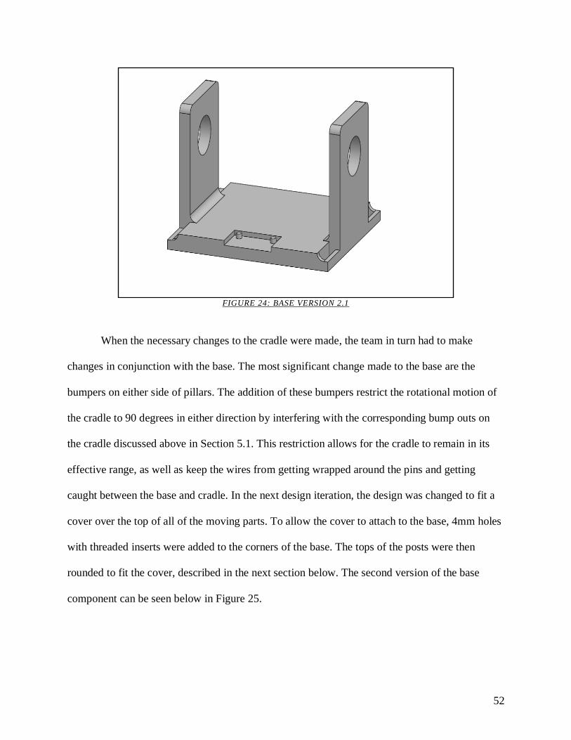
52
FIGURE 24: BASE VERSION 2.1
When the necessary changes to the cradle were made, the team in turn had to make
changes in conjunction with the base. The most significant change made to the base are the
bumpers on either side of pillars. The addition of these bumpers restrict the rotational motion of
the cradle to 90 degrees in either direction by interfering with the corresponding bump outs on
the cradle discussed above in Section 5.1. This restriction allows for the cradle to remain in its
effective range, as well as keep the wires from getting wrapped around the pins and getting
caught between the base and cradle. In the next design iteration, the design was changed to fit a
cover over the top of all of the moving parts. To allow the cover to attach to the base, 4mm holes
with threaded inserts were added to the corners of the base. The tops of the posts were then
rounded to fit the cover, described in the next section below. The second version of the base
component can be seen below in Figure 25.
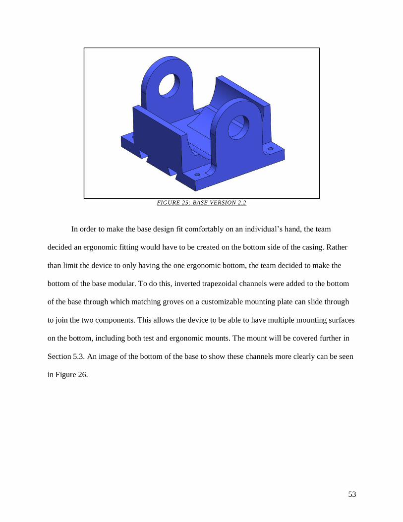
53
FIGURE 25: BASE VERSION 2.2
In order to make the base design fit comfortably on an individual’s hand, the team
decided an ergonomic fitting would have to be created on the bottom side of the casing. Rather
than limit the device to only having the one ergonomic bottom, the team decided to make the
bottom of the base modular. To do this, inverted trapezoidal channels were added to the bottom
of the base through which matching groves on a customizable mounting plate can slide through
to join the two components. This allows the device to be able to have multiple mounting surfaces
on the bottom, including both test and ergonomic mounts. The mount will be covered further in
Section 5.3. An image of the bottom of the base to show these channels more clearly can be seen
in Figure 26.
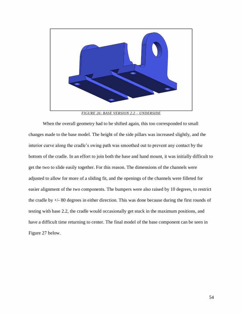
54
FIGURE 26: BASE VERSION 2.2 – UNDERSIDE
When the overall geometry had to be shifted again, this too corresponded to small
changes made to the base model. The height of the side pillars was increased slightly, and the
interior curve along the cradle’s swing path was smoothed out to prevent any contact by the
bottom of the cradle. In an effort to join both the base and hand mount, it was initially difficult to
get the two to slide easily together. For this reason. The dimensions of the channels were
adjusted to allow for more of a sliding fit, and the openings of the channels were filleted for
easier alignment of the two components. The bumpers were also raised by 10 degrees, to restrict
the cradle by +/- 80 degrees in either direction. This was done because during the first rounds of
testing with base 2.2, the cradle would occasionally get stuck in the maximum positions, and
have a difficult time returning to center. The final model of the base component can be seen in
Figure 27 below.
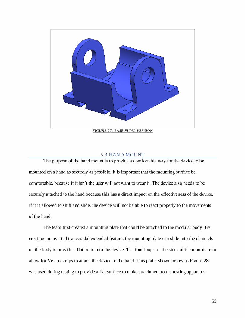
55
FIGURE 27: BASE FINAL VERSION
5.3 HAND MOUNT
The purpose of the hand mount is to provide a comfortable way for the device to be
mounted on a hand as securely as possible. It is important that the mounting surface be
comfortable, because if it isn’t the user will not want to wear it. The device also needs to be
securely attached to the hand because this has a direct impact on the effectiveness of the device.
If it is allowed to shift and slide, the device will not be able to react properly to the movements
of the hand.
The team first created a mounting plate that could be attached to the modular body. By
creating an inverted trapezoidal extended feature, the mounting plate can slide into the channels
on the body to provide a flat bottom to the device. The four loops on the sides of the mount are to
allow for Velcro straps to attach the device to the hand. This plate, shown below as Figure 28,
was used during testing to provide a flat surface to make attachment to the testing apparatus

56
more effective. This mounting plate was then used as a base model for the ergonomic hand
mount.
FIGURE 28: BASE MOUNT
When designing the hand mount, the team decided that the most effective method would
be a design that fits the surface of the average hand as accurately as possible. A 3D model of a
male’s left hand was found on the design community page “GrabCAD” and used as a surface
geometry reference. The hand was inserted into the base mount file and located to a reference
position below the base mount, as can be seen in Figure 29 below.
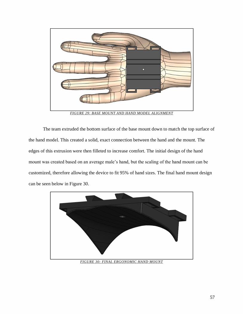
57
FIGURE 29: BASE MOUNT AND HAND MODEL ALIGNMENT
The team extruded the bottom surface of the base mount down to match the top surface of
the hand model. This created a solid, exact connection between the hand and the mount. The
edges of this extrusion were then filleted to increase comfort. The initial design of the hand
mount was created based on an average male’s hand, but the scaling of the hand mount can be
customized, therefore allowing the device to fit 95% of hand sizes. The final hand mount design
can be seen below in Figure 30.
FIGURE 30: FINAL ERGONOMIC HAND MOUNT

58
5.4 GYROSCOPE
With the new base and cradle system in place, there was now less room in between the
pillars of the cradle for the original gyroscope to fit. With these new constraints, the dimensions
of the gyroscope had to be altered to fit the new arrangement. The overall diameter of the
gyroscope was decreased to 45 mm across, thereby creating 2 mm on either side between the
gyroscope and cradle pillars. A model of the gyroscope can be seen in Figure 31 below.
FIGURE 31: GYROSCOPE FINAL VERSION
Using the procedure lined out in Section 4.4.1, the team was unable to achieve the desired
shrink fit due to the gyroscope not fitting over the shaft. Two attempts were conducted using a
gyroscope with a shaft hole size of 4.93 mm. After conducting our procedure, the team
discovered that either the measured the dimensions of the motor were incorrect, or there was not
enough clearance between the motor shaft and gyroscope, because once the gyroscope was
heated, it did not slide onto the motor as intended. These attempts resulted in the bending of the
motor shaft, making it unusable. For the final disk, the hole was expanded to 4.95 mm to match
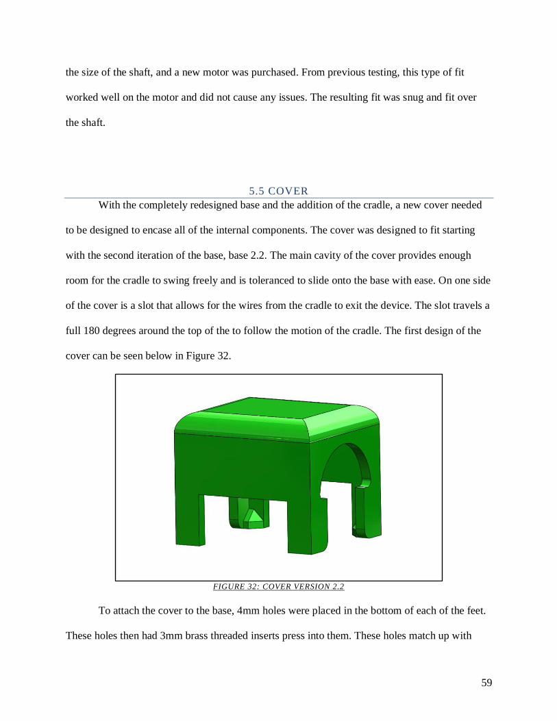
59
the size of the shaft, and a new motor was purchased. From previous testing, this type of fit
worked well on the motor and did not cause any issues. The resulting fit was snug and fit over
the shaft.
5.5 COVER
With the completely redesigned base and the addition of the cradle, a new cover needed
to be designed to encase all of the internal components. The cover was designed to fit starting
with the second iteration of the base, base 2.2. The main cavity of the cover provides enough
room for the cradle to swing freely and is toleranced to slide onto the base with ease. On one side
of the cover is a slot that allows for the wires from the cradle to exit the device. The slot travels a
full 180 degrees around the top of the to follow the motion of the cradle. The first design of the
cover can be seen below in Figure 32.
FIGURE 32: COVER VERSION 2.2
To attach the cover to the base, 4mm holes were placed in the bottom of each of the feet.
These holes then had 3mm brass threaded inserts press into them. These holes match up with
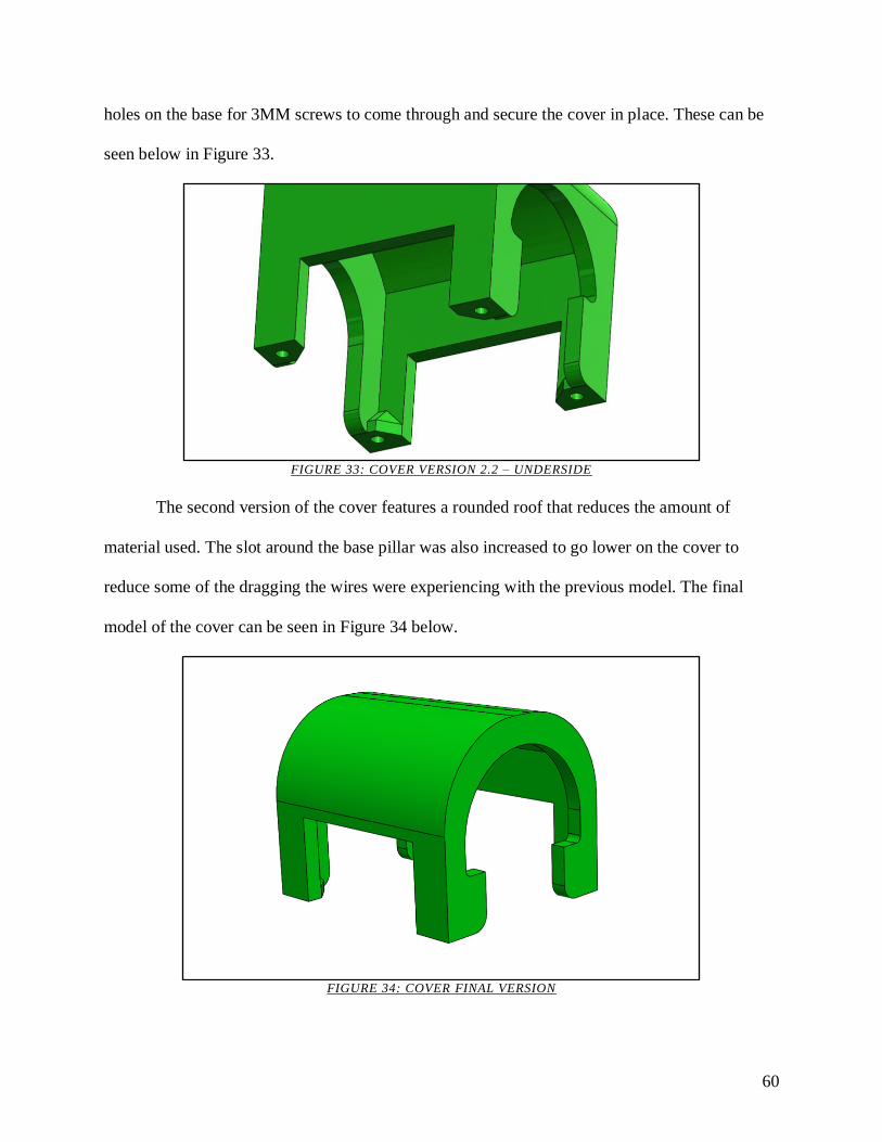
60
holes on the base for 3MM screws to come through and secure the cover in place. These can be
seen below in Figure 33.
FIGURE 33: COVER VERSION 2.2 – UNDERSIDE
The second version of the cover features a rounded roof that reduces the amount of
material used. The slot around the base pillar was also increased to go lower on the cover to
reduce some of the dragging the wires were experiencing with the previous model. The final
model of the cover can be seen in Figure 34 below.
FIGURE 34: COVER FINAL VERSION
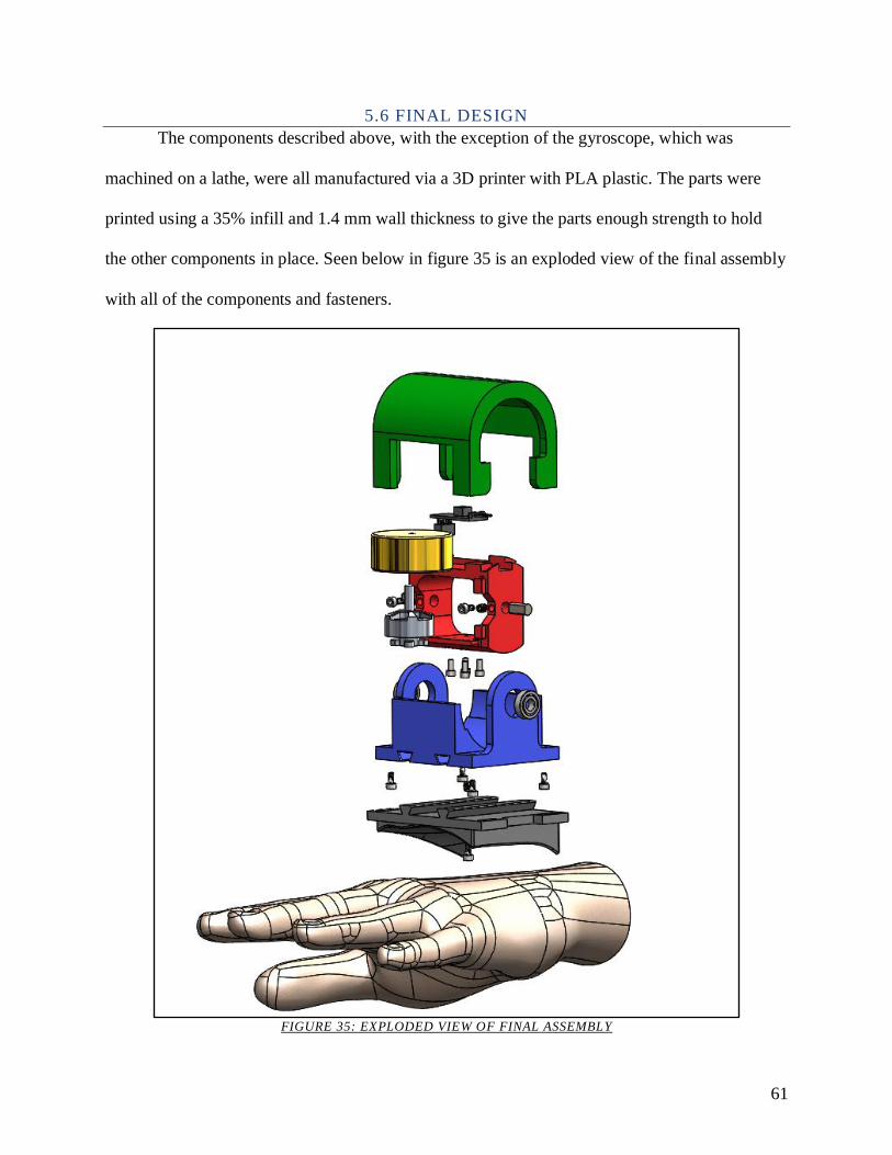
61
5.6 FINAL DESIGN
The components described above, with the exception of the gyroscope, which was
machined on a lathe, were all manufactured via a 3D printer with PLA plastic. The parts were
printed using a 35% infill and 1.4 mm wall thickness to give the parts enough strength to hold
the other components in place. Seen below in figure 35 is an exploded view of the final assembly
with all of the components and fasteners.
FIGURE 35: EXPLODED VIEW OF FINAL ASSEMBLY
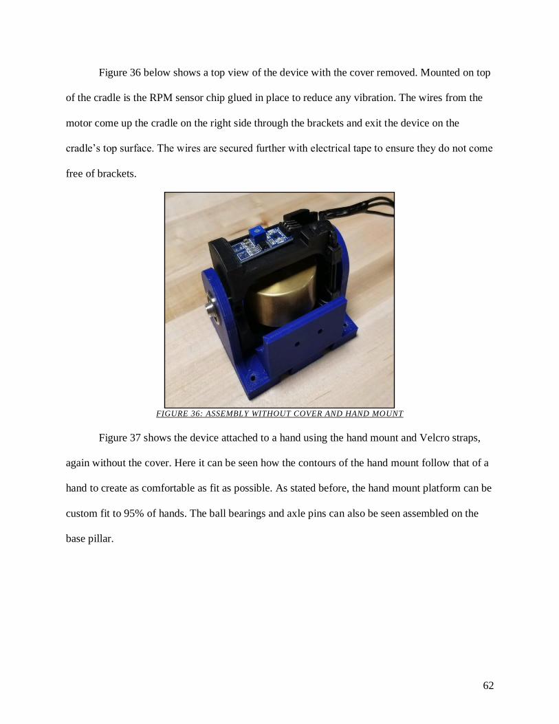
62
Figure 36 below shows a top view of the device with the cover removed. Mounted on top
of the cradle is the RPM sensor chip glued in place to reduce any vibration. The wires from the
motor come up the cradle on the right side through the brackets and exit the device on the
cradle’s top surface. The wires are secured further with electrical tape to ensure they do not come
free of brackets.
FIGURE 36: ASSEMBLY WITHOUT COVER AND HAND MOUNT
Figure 37 shows the device attached to a hand using the hand mount and Velcro straps,
again without the cover. Here it can be seen how the contours of the hand mount follow that of a
hand to create as comfortable as fit as possible. As stated before, the hand mount platform can be
custom fit to 95% of hands. The ball bearings and axle pins can also be seen assembled on the
base pillar.
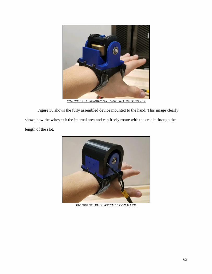
63
FIGURE 37: ASSEMBLY ON HAND WITHOUT COVER
Figure 38 shows the fully assembled device mounted to the hand. This image clearly
shows how the wires exit the internal area and can freely rotate with the cradle through the
length of the slot.
FIGURE 38: FULL ASSEMBLY ON HAND
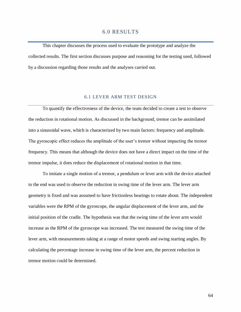
64
6.0 RESULTS
This chapter discusses the process used to evaluate the prototype and analyze the
collected results. The first section discusses purpose and reasoning for the testing used, followed
by a discussion regarding those results and the analyses carried out.
6.1 LEVER ARM TEST DESIGN
To quantify the effectiveness of the device, the team decided to create a test to observe
the reduction in rotational motion. As discussed in the background, tremor can be assimilated
into a sinusoidal wave, which is characterized by two main factors: frequency and amplitude.
The gyroscopic effect reduces the amplitude of the user’s tremor without impacting the tremor
frequency. This means that although the device does not have a direct impact on the time of the
tremor impulse, it does reduce the displacement of rotational motion in that time.
To imitate a single motion of a tremor, a pendulum or lever arm with the device attached
to the end was used to observe the reduction in swing time of the lever arm. The lever arm
geometry is fixed and was assumed to have frictionless bearings to rotate about. The independent
variables were the RPM of the gyroscope, the angular displacement of the lever arm, and the
initial position of the cradle. The hypothesis was that the swing time of the lever arm would
increase as the RPM of the gyroscope was increased. The test measured the swing time of the
lever arm, with measurements taking at a range of motor speeds and swing starting angles. By
calculating the percentage increase in swing time of the lever arm, the percent reduction in
tremor motion could be determined.
65
To do this, the team conducted testing and analysis in both theory and practice. Using
information on the amplitude and frequency of Essential Tremor, the most common tremor
disorder, the team determined important numerical factors such as the degrees of rotation caused
by tremor motion, angular velocity and acceleration of the tremor, and frequency of motion.
These numbers were referenced for creating an accurate model that described the summation of
the forces during the use of the team’s device. The mathematical model shown in Section 2.6
was used for these calculations. The complete model can also be seen in Appendix E. For the
practical testing, the team used the lever arm experiment stated above.
In the lever arm test, a high-speed camera was used to capture the swing duration of the
lever arm at various angular displacements. For displacements of 5, 10 and 15 degrees, three
trials were conducted with the gyroscope at a constant speed of 0, 6000, 10000, 140000, and
18000 RPM. The footage was then analyzed to determine the time the lever arm took to fall from
its set angular displacement to 0 degrees. The average of these times were then used to compare
the time of the freefall swing and determine the percent increase in swing time. A step by step
procedure of the lever arm experiment is located in Appendix D.
6.2 FULL CRADLE ROTATION TEST
The initial testing conducted had the cradle positioned to the left in a maximum -90-
degree rotation. This allowed the cradle to have a full 180 degrees to rotate. For this test, the
Casio EXILIM high speed camera was used to capture the motion of the lever arm. Due to the
hardware limitation of the camera, the 239.76 frame per second footage was converted to a
playback speed of 29.97 frame per second (fps). Therefore, a time conversion was required to
convert the playback speed to real time. The proportion was calculated to be one second of

66
239.76 fps video was equivalent to 8 seconds of playback in 29.97 fps footage. The Movavi
video editor was used to obtain the timestamp of the initial and final angle of the lever arm.
Below in Figure 39 are the results of the full rotation test.
FIGURE 39: LEVER ARM SWING DURATION VS. GYROSCOPE RPM FOR 180 DEG. OF CRADLE ROTATION
The raw data can be found in the Appendix G. For the first set of data at 5 degrees, the
time of freefall of the lever arm is the shortest at 0.2 seconds. When the gyroscope was spun to
6000 RPM, a 50% increase in swing time was computed. At 10,000 RPM, the increase in time of
swing was approximately 143%. However, at 14,000 and 18,000 RPM, the percent increase is
16% and 21% respectively. In the second set of data of 10 degrees, the freefall time was 0.24
seconds. The percent increase in time was 40% at 6000 RPM, 90% at 10,000 RPM, 4% at 14,000
RPM, and 69% at 18,000 RPM. In the third set of data at 15 degrees, the freefall time was 0.3
0
0.1
0.2
0.3
0.4
0.5
0.6
5 Degrees 10 Degrees 15 Degrees
Leve
r A
rm S
win
g D
ura
tio
n (
Sec.
)
Lever Arm Swing Duration vs. Gyroscope RPM for 180 Degrees of Cradle Rotation
0 RPM 6000 RPM 10000 RPM 14000 RPM 18000 RPM
67
seconds. The percent increase at 6000 RPM was 10%, at 10,000 RPM was 33%, at 14,000 RPM
was 3%, and at 18,000 RPM was 12%.
It is evident in this relationship that the increase in RPM increased the swing time of the
lever arm. This is visible for all initial angle sets at 6000 and 10,000 RPM. This proved our
hypothesis and the simulation in the mathematical model. Additionally, it was also observed the
percent increase diminishes as the angular displacement of the lever arm grew from 5 to 15
degrees. However, a point of error was denoted in the data sets at an RPM of 14,000 and 18,000.
The team observed that the gyroscope had an effect on the period of the lever arm, but this effect
occurred after the lever arm had passed through the determined end point of 0 degrees. The
gyroscope was also observed to not react instantly to the motion of the swing. In the footage of
14,000 and 18,000 RPM, the cradle was seen to rotate after the lever arm passed 0 degrees. The
results show the error as swing times were similar to the original freefall time where the
gyroscope was disabled.
The team believes that the reasoning as to why the gyroscope did not react in time was
due to the initial angle of the cradle. With the cradle set at the -90 degrees to allow for the full
180 degrees of rotation, the gyroscope was taken out of its effective range, where the motion of
the lever arm would not have a real effect on the motion of the cradle. The team then
hypothesized the device would react immediately if the cradle’s starting angle was set to 0
degrees. This decreases the overall allowed rotation of the cradle, however, would allow the
gyroscope to rotate instantly at the start of the swing. This second test is discussed further below
in Section 6.3.

68
6.3 HALF CRADLE ROTATION TEST
Following through on the team’s reviews from the first lever arm test, the test was
repeated in full, this time with the cradle oriented at 0 degrees at the start of the swing. The
cradle oriented in this position, the prototype’s resistive effects would be taking place
instantaneously, compared to the previous test. For this test, the team switched to the GoPro 7
video camera to capture the lever arm motion. The advantage of the GoPro over the Casio
EXILIM was the higher resolution of 1080p at the same frame rate. Additionally, the footage
was saved in real time, so no time conversion was needed as in first experiment. Adobe Premiere
Pro was used to view the footage because it was successfully able to open the video files and had
the ability to scrub through the timeline accurately. The swing time was calculated using the
reciprocal of 239.76 fps to find the time displayed per frame and multiplied by the number of
frames. Assuming a constant framerate, one frame displays for 0.00417 seconds. The swing time
results for the second test are shown below in Figure 40.
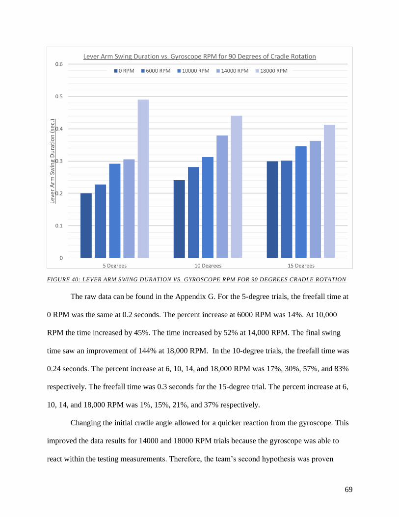
69
FIGURE 40: LEVER ARM SWING DURATION VS. GYROSCOPE RPM FOR 90 DEGREES CRADLE ROTATION
The raw data can be found in the Appendix G. For the 5-degree trials, the freefall time at
0 RPM was the same at 0.2 seconds. The percent increase at 6000 RPM was 14%. At 10,000
RPM the time increased by 45%. The time increased by 52% at 14,000 RPM. The final swing
time saw an improvement of 144% at 18,000 RPM. In the 10-degree trials, the freefall time was
0.24 seconds. The percent increase at 6, 10, 14, and 18,000 RPM was 17%, 30%, 57%, and 83%
respectively. The freefall time was 0.3 seconds for the 15-degree trial. The percent increase at 6,
10, 14, and 18,000 RPM was 1%, 15%, 21%, and 37% respectively.
Changing the initial cradle angle allowed for a quicker reaction from the gyroscope. This
improved the data results for 14000 and 18000 RPM trials because the gyroscope was able to
react within the testing measurements. Therefore, the team’s second hypothesis was proven
0
0.1
0.2
0.3
0.4
0.5
0.6
5 Degrees 10 Degrees 15 Degrees
Leve
r A
rm S
win
g D
ura
tio
n (
sec.
)Lever Arm Swing Duration vs. Gyroscope RPM for 90 Degrees of Cradle Rotation
0 RPM 6000 RPM 10000 RPM 14000 RPM 18000 RPM
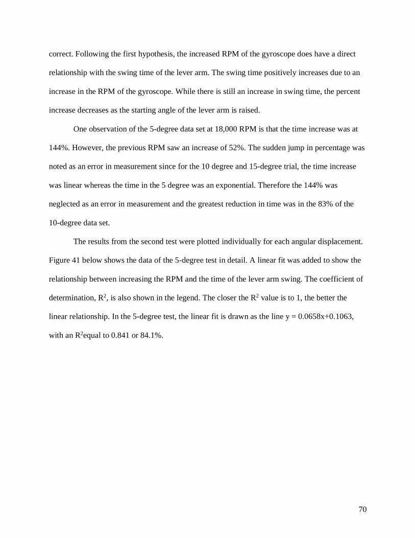
70
correct. Following the first hypothesis, the increased RPM of the gyroscope does have a direct
relationship with the swing time of the lever arm. The swing time positively increases due to an
increase in the RPM of the gyroscope. While there is still an increase in swing time, the percent
increase decreases as the starting angle of the lever arm is raised.
One observation of the 5-degree data set at 18,000 RPM is that the time increase was at
144%. However, the previous RPM saw an increase of 52%. The sudden jump in percentage was
noted as an error in measurement since for the 10 degree and 15-degree trial, the time increase
was linear whereas the time in the 5 degree was an exponential. Therefore the 144% was
neglected as an error in measurement and the greatest reduction in time was in the 83% of the
10-degree data set.
The results from the second test were plotted individually for each angular displacement.
Figure 41 below shows the data of the 5-degree test in detail. A linear fit was added to show the
relationship between increasing the RPM and the time of the lever arm swing. The coefficient of
determination, R2, is also shown in the legend. The closer the R2 value is to 1, the better the
linear relationship. In the 5-degree test, the linear fit is drawn as the line y = 0.0658x+0.1063,
with an R2equal to 0.841 or 84.1%.

71
FIGURE 41: 5 DEGREE TEST DATA WITH LINE OF BEST FIT
This process was repeated for the 10 degree and 15-degree trials. The 10-degree angular
displacement has an equation of y = 0.0496x + 0.232, with an R2 value of 0.979 (98%). The 15-
degree angular displacement has an equation of y = 0.0287x + 0.287, with an R2 value of 0.933
(93%). The slope of the relationship between RPM and time was taken and plotted against the
angular displacement.
An observation from the results was that increasing the angular displacement decreased
the effect of the gyroscope acting on the lever arm. In Figure 42 below, the slope of the RPM
relationship was plotted against the displacement angle in degrees. As the slope decreases to
zero, the effectiveness of the gyroscope would fail to affect the time of the swing regardless of
the gyroscope speed. The equation of the linear fit is y = -3.71*10^-3 x + 0.0851. Extrapolating
y = 0.0658x + 0.1063R² = 0.8407
0
0.1
0.2
0.3
0.4
0.5
0.6
0 RPM 6000 RPM 10000 RPM 14000 RPM 18000 RPM
Leve
r A
rm S
win
g D
ura
tio
n (
sec.
)Gyroscope Effectiveness vs. RPM at 5 Degrees of Lever Arm Swing
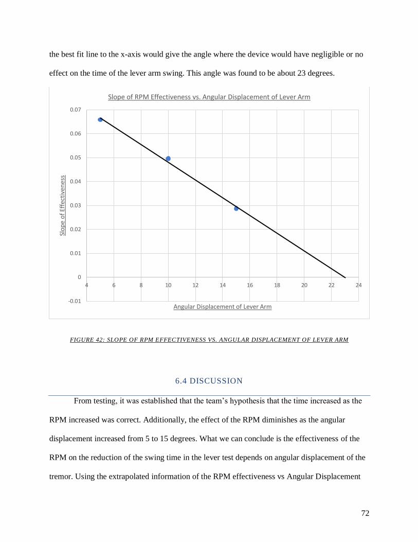
72
the best fit line to the x-axis would give the angle where the device would have negligible or no
effect on the time of the lever arm swing. This angle was found to be about 23 degrees.
FIGURE 42: SLOPE OF RPM EFFECTIVENESS VS. ANGULAR DISPLACEMENT OF LEVER ARM
6.4 DISCUSSION
From testing, it was established that the team’s hypothesis that the time increased as the
RPM increased was correct. Additionally, the effect of the RPM diminishes as the angular
displacement increased from 5 to 15 degrees. What we can conclude is the effectiveness of the
RPM on the reduction of the swing time in the lever test depends on angular displacement of the
tremor. Using the extrapolated information of the RPM effectiveness vs Angular Displacement
-0.01
0
0.01
0.02
0.03
0.04
0.05
0.06
0.07
4 6 8 10 12 14 16 18 20 22 24
Slo
pe
of
Effe
ctiv
enes
s
Angular Displacement of Lever Arm
Slope of RPM Effectiveness vs. Angular Displacement of Lever Arm
73
in Figure #2, we can conclude that for our lever arm setup, the maximum RPM effectiveness is at
very small angles and the angle when the RPM has no effect on the swing of the is at 23 degrees.
What this means for a tremor is that the device is very efficient in reducing tremor amplitude in
rotational angles of 0 to 10 degrees. However, at 10 to 23 degrees, the efficiency decreases. To
increase the effectiveness, a higher RPM is required, however that may be exponentially higher
to achieve the same effect.
6.5 SIMULATION TEST DESIGN
During the course of testing, the team came up with a second method that could be used
to test the effectiveness of the device. Using a linear actuator that acted at the same amplitude
and frequency of a hand tremor, the team speculated a device that could actively recreate the
conditions of a tremor. The device would consist of a flat piece of wood, the width of which
being the average width of a male’s hand, would be suspended along its length about 6 inches
from the ground between two posts, each with an axle and bearing to connect them and allow the
wood platform to pivot. A linear actuator, tuned to produce the same frequency, force, and
displacement of a hand tremor (based on angular displacement and the width of the wood),
would then be mounted below the platform and attached to one of the edges. When the linear
actuator is activated, it would cause the wood platform to oscillate at the same frequency and
amplitude of a hand tremor. The team would then be able to attach the prototype to the platform
and observe how the device interacted with the tremor. Figure 43 below shows a model of what
the device would look like, and a full procedure for this can be seen in Appendix H.
Unfortunately, due to time constraints, this second device could not be built.
74
FIGURE 43: SIMULATOR TEST RIG DESIGN
75
7.0 RECOMMENDATIONS & CONCLUSIONS
Upon completion of this project, there are a number of recommendations that the group
would recommend be taken given more time to continue development of the prototype.
1. Shrink components: Currently, the device is bulky to wear, and the electrical components
are contained within a large acrylic box. Since the structure was manufactured out of 3D printed
PLA plastic, a certain thickness had to be incorporated to ensure structural rigidity of the
components, and thus increasing the dimensions. If the base, cradle and cover were to be
manufactured using plastic injection molding, the size could be reduced. Additionally, the
electronics can be arranged to be wearable, say in a fanny pack of sorts.
2. More dense material for the gyroscope: Increasing the effectiveness of the gyroscope
comes at the cost of high angular velocity and mass. Brass was chosen for its density and ease of
machinability for the device. However, using denser materials than brass is recommended
because this can increase the effectiveness of the gyroscope without impacting the size of the
disk.
3. Balancing of the gyroscope: One avenue of research not pursued due to its complexity
was the dynamic balancing of the gyroscope. Balancing the gyroscope would reduce the
vibration, as well as noise being generated within the system.
4. Incorporate more sensing equipment and code: The team considered having the prototype
be smart sensing. Using an array of sensors such as the accelerometer and gyroscope, the idea
was to create a self-sensing device that when a tremor was detected, would adjust the motor
RPM accordingly. A combination of an Arduino and Raspberry PI was considered to allow for
interconnectivity between the sensors and the PI to store the sensor data and return a signal to
76
adjust the motor speed. Research had been done to study the relationship between levels of
tremor and transducer readings, however due to the complexity of this feature, it was dropped.
5. Improve hand attachment mechanism: The team would like to recommend improving the
comfort of the device by constructing a new hand attachment mechanism. The 3D printed mount
plate allows a customization to a variety of hand sizes, yet the attachment method of Velcro
straps had room for improvement. The team considered the possibility of using a fingerless glove
and the mount would be either glued, sewn or slotted into the glove.
6. Hand tremor simulation: In testing the device, the team brainstormed an alternative
experiment that would simulate a tremor on a test platform. As discussed above in Section 6.5,
the team was unable to successful build and conduct this test. However, the team believes that
this test would be the next step in determining the effectiveness of the prototype.
Overall, the prototype proved to be successful in both theory and practice. The device
comfortably fits on a hand and reduces the magnitude of hand tremors. As can be seen in our
results, testing demonstrated an 80% reduction in tremors. The team believes that further testing
with the tremor simulation device outlined above has the potential to yield more enlightening
results. From the mathematical model, we concluded that our design is theoretically capable of
increasing the reduction in tremors up to 87%.
77
WORKS CITED
Allen, Brendon Connor. "Effect of Gyroscope Parameters on Gyroscopic Tremor Suppression in a
Single Degree of Freedom." Brigham Young University, 2018. Print.
APDA. "Tremor in Parkinson's." American Parkinson Disease Association (APDA). Web. Nov 12,
2018 <https://www.apdaparkinson.org/what-is-parkinsons/symptoms/tremor/>.
Arnon, Stephen S., et al. "Botulinum Toxin as a Biological Weapon: Medical and Public Health
Management." JAMA 285.8 (2001): 1059-70. Web. Nov 20, 2018.
Britannica. "Cerebellum." Encyclopaedia Britannica. Web. Nov 12, 2018
<https://www.britannica.com/science/cerebellum>.
"Brotherhobby Returner R3 2207 2550kv Brushless Motor." getfpv.com. Web. Dec 14, 2018
<https://www.getfpv.com/brotherhobby-returner-r3-2207-2550kv-brushless-
motor.html?gclid=Cj0KCQiAxs3gBRDGARIsAO4tqq2F7kjW_5LxBgdEc12poV4A_KejaYzYN
bTCacM-Rdlb7TczZ2ofZcEaApYsEALw_wcB>.
Brozek, J. L., et al. "Original Article." Allergy 63.1 (2008): 38. Toxicology Abstracts. Web.
Burblla, L. F., et al. "The Science of Parkinson's." Sept 7, 2017. Web. Dec 10, 2018
<https://scienceofparkinsons.com/tag/l-dopa/>.
Burke, Deborah A., Robert A. Hauser, and Theresa A. McClain. "Essential Tremor." Medscape. Oct
22, 2018. Web. 12/6/2018 <https://emedicine.medscape.com/article/1150290-overview>.
Business Industry Reports. "World Deep Brain Stimulation Market Double Digit Growth Rate
Forecasts To 2025." Medium.com. Dec 10, 2017. Web. Dec 14, 2018
<https://medium.com/@Precisemarketre/world-deep-brain-stimulation-market-double-digit-
growth-rate-forecasts-to-2025-a196c37aa357>.
78
Calzetti, Stefano, et al. "Frequency/Amplitude Characteristics of Postural Tremor of the Hands in a
Population of Patients with Bilateral Essential Tremor: Implications for the Classification and
Mechanism of Essential Tremor." Journal of Neurology, Neurosurgery & Psychiatry
(1987)Web.
Crawford, Paul, and Ethan E. Zimmerman. "Differentiation and Diagnosis of Tremor." American
Academy of Family Physicians (AAFP). Mar 15, 2011. Web. Nov 11, 2018
<https://www.aafp.org/afp/2011/0315/p697.html>.
Deuschl, Günther, et al. "A Randomized Trial of Deep-Brain Stimulation for Parkinson's Disease."
New England Journal of Medicine 355.9 (2006): 896-908. Web. Nov 28, 2018.
"Drug Treatments for Essential Tremor." WebMD. Web. Nov 20, 2018
<https://www.webmd.com/epilepsy/guide/essential-tremor-drug>.
"Eatwell Assistive Tableware Set." Web. December 4, 2018 <https://www.eatwellset.com/product-
page/copy-of-8-piece-eatwell-assistive-tableware-set>.
Elble, Rodger J., and James McNames. "Using Portable Transducers to Measure Tremor Severity."
(2016)Web.
Elble, Rodger J., Ludy Shih, and Jeffrey W. Cozzens. "Surgical Treatments for Essential Tremor."
Expert Review of Neurotherapeutics 18.4 (2018): 303-21. Web. Dec 4, 2018.
Elble, Rodger J. "Defining Dystonic Tremor." PMC (2012)Web.
Elias, W. Jeffrey, et al. "A Randomized Trial of Focused Ultrasound Thalamotomy for Essential
Tremor." The New England Journal of Medicine 375.8 (2016): 730-9. Web. Dec 2, 2018.
Essential Tremor: Common Medications.Web. Nov 26, 2018.
"GyroGlove." Web. 12/4/18 <https://gyrogear.co/gyroglove>.
79
Healthwise Staff. "Thalamotomy for Parkinson's Disease." UW Health. Oct 9, 2017. Web. Nov 20,
2018 <https://www.uwhealth.org/health/topic/surgicaldetail/thalamotomy-for-parkinson-s-
disease/aa140809.html>.
Hedera, Peter. "What Is the Best Treatment for Essential Tremor?" MDedge. Nov 23, 2015. Web.
Nov 28, 2018 <https://www.mdedge.com/neurologyreviews/article/104128/movement-
disorders/what-best-treatment-essential-tremor>.
Jankovic, Joseph, and NORD. "Primary Orthostatic Tremor." National Organization for Rare
Diseases (Nord). 2017. Web. Nov 12, 2018 <https://rarediseases.org/rare-diseases/primary-
orthostatic-tremor/>.
Joseph, J. P., and K. Rajappan. "Radiofrequency Ablation of Cardiac Arrhythmias: Past, Present and
Future." (2012)Web.
Jung, Na Young, and Jin Woo Chang. "Magnetic Resonance-Guided Focused Ultrasound in
Neurosurgery: Taking Lessons from the Past to Inform the Future." Journal of Korean
Medical Science 33.44 (2018)CrossRef. Web.
"Keatlery Weighted Utensils." Web. December 4, 2018 <http://www.elderstore.net/keatlery.aspx>.
Kent, Michael. The Oxford Dictionary of Sports Science & Medicine. 3rd ed. Oxford University
Press, 2016. Print.
"Liftware Steady." Web. December 4, 2018 <https://www.liftware.com/steady/>.
Mayo Clinic. "Parkinson's Disease." Mayo Clinic. Jun 30, 2018. Web. Nov 12, 2018
<https://www.mayoclinic.org/diseases-conditions/parkinsons-disease/symptoms-causes/syc-
20376055>.
Niemann, Nicki, and Joseph Jankovic. "Botulinum Toxin for the Treatment of Hand Tremor." Toxins
10.7 (2018): 299. PubMed. Web.

80
NINDS, and National Institutes of Health. "Tremor Fact Sheet." National Institute of Neurological
Disorders and Stroke (NINDS). May, 2017. Web. Nov 11, 2018
<https://www.ninds.nih.gov/Disorders/Patient-Caregiver-Education/Fact-Sheets/Tremor-Fact-
Sheet>.
Parkin, Simon. "Hope in a Glove for Parkinson's Patients." Technologyreviews.com. Jan 14, 2016.
Web. <https://www.technologyreview.com/s/545456/hope-in-a-glove-for-parkinsons-
patients/>.
"Readi Steadi." 2016. Web. December 4, 2018 <https://www.readi-steadi.com/details.html>.
"Rocker Knife with T-handle." Web. December 4, 2018 <https://www.caregiverproducts.com/rocker-
knife-t-handle.html>.
"S'up Spoon Black." Sup-products.com. Web. December 4, 2018 <https://www.sup-
products.com/product/sup-spoon-black/>.
Salat, David, and Eduardo Tolosa. "Levodopa in the Treatment of Parkinson's Disease: Current
Status and New Developments." Journal of Parkinson's disease 3.3 (2013): 255. MEDLINE.
Web.
"Steadiwear." 2018. Web. <https://www.steadiwear.com/>.
"SteadyRest." 2016. Web. December 4, 2018 <https://www.steadyrest.org/>.
"Turnigy 5000mAh 5S 30C Lipo Pack w/XT-90." HobbyKing. Web. Dec 14, 2018
<https://hobbyking.com/en_us/turnigy-5000mah-5s-30c-lipo-pack-xt-90.html>.
"YEP 60A (2~6S) SBEC Brushless Speed Controller." HobbyKing. Web. Dec 14, 2018
<https://hobbyking.com/en_us/hobbyking-yep-60a-2-6s-sbec-brushless-speed-
controller.html>.

81
APPENDIX A: THERMAL EXPANSION CALCULATIONS FOR
SHRINK FIT
TABLE 2: NOMENCLATURE FOR THERMAL EXPANSION CALCULATIONS
Variable Units
D = Distance Millimeters
T = Temperature Degrees Celsius
α = Thermal Conductivity 10−6ᵒ𝐶
Calculation Parameters:
These calculations will be based off of 3 scenarios: Worst case, Measured Case, and Best
Case. The worst case displays what will happen if the reaming tool is exactly 4.93mm (or
4.95mm) and the shaft is on the highest end of its tolerance. Measured case will display what
will happen if the items are the actual size they were measured to and in the case of the reamer
being 4.93mm (or 4.95mm). The best case will be if the shaft diameter is at the low side of the
tolerance and the reaming tool is oversized. For purposes of the design, the worst-case scenario
will be the basis the design.
Given:
Variables/Values Description/Reasoning
𝐷𝑚𝑒𝑎𝑠 = 4.963 𝑚𝑚 The expected diameter of the shaft
𝐷𝑚𝑎𝑥 = 4.964 𝑚𝑚 The diameter on the upper end of the tolerance
𝐷𝑏𝑒𝑠𝑡 = 4.962 𝑚𝑚 The diameter on the lower end of the tolerance
𝑇1 = 21ᵒ𝐶 Room temperature
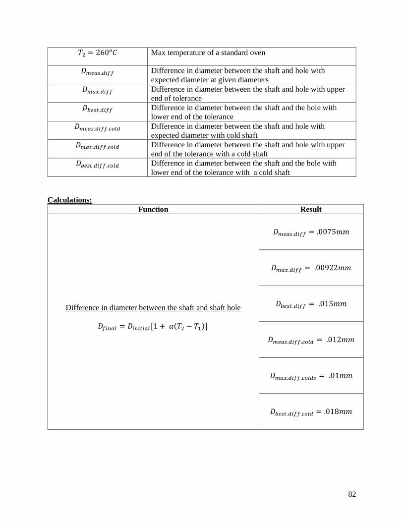
82
𝑇2 = 260ᵒ𝐶 Max temperature of a standard oven
𝐷𝑚𝑒𝑎𝑠.𝑑𝑖𝑓𝑓 Difference in diameter between the shaft and hole with
expected diameter at given diameters
𝐷𝑚𝑎𝑥.𝑑𝑖𝑓𝑓 Difference in diameter between the shaft and hole with upper
end of tolerance
𝐷𝑏𝑒𝑠𝑡.𝑑𝑖𝑓𝑓 Difference in diameter between the shaft and the hole with
lower end of the tolerance
𝐷𝑚𝑒𝑎𝑠.𝑑𝑖𝑓𝑓.𝑐𝑜𝑙𝑑 Difference in diameter between the shaft and hole with
expected diameter with cold shaft
𝐷𝑚𝑎𝑥.𝑑𝑖𝑓𝑓.𝑐𝑜𝑙𝑑 Difference in diameter between the shaft and hole with upper
end of the tolerance with a cold shaft
𝐷𝑏𝑒𝑠𝑡.𝑑𝑖𝑓𝑓.𝑐𝑜𝑙𝑑 Difference in diameter between the shaft and the hole with
lower end of the tolerance with a cold shaft
Calculations:
Function Result
Difference in diameter between the shaft and shaft hole
𝐷𝑓𝑖𝑛𝑎𝑙 = 𝐷𝑖𝑛𝑖𝑡𝑖𝑎𝑙[1 + 𝛼(𝑇2 − 𝑇1)]
𝐷𝑚𝑒𝑎𝑠.𝑑𝑖𝑓𝑓 = .0075𝑚𝑚
𝐷𝑚𝑎𝑥.𝑑𝑖𝑓𝑓 = .00922𝑚𝑚
𝐷𝑏𝑒𝑠𝑡.𝑑𝑖𝑓𝑓 = .015𝑚𝑚
𝐷𝑚𝑒𝑎𝑠.𝑑𝑖𝑓𝑓.𝑐𝑜𝑙𝑑 = .012𝑚𝑚
𝐷𝑚𝑎𝑥.𝑑𝑖𝑓𝑓.𝑐𝑜𝑙𝑑𝑠 = .01𝑚𝑚
𝐷𝑏𝑒𝑠𝑡.𝑑𝑖𝑓𝑓.𝑐𝑜𝑙𝑑 = .018𝑚𝑚
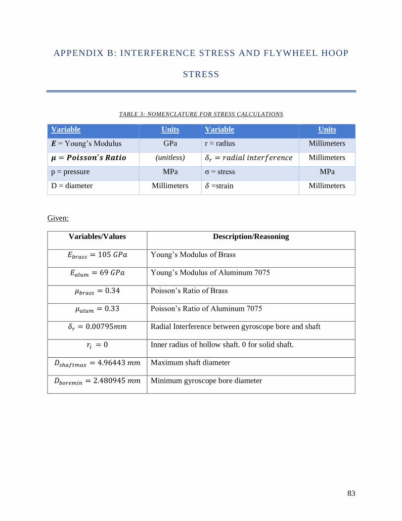
83
APPENDIX B: INTERFERENCE STRESS AND FLYWHEEL HOOP
STRESS
TABLE 3: NOMENCLATURE FOR STRESS CALCULATIONS
Variable Units Variable Units
𝑬 = Young’s Modulus GPa r = radius Millimeters
𝝁 = 𝑷𝒐𝒊𝒔𝒔𝒐𝒏′𝒔 𝑹𝒂𝒕𝒊𝒐 (unitless) 𝛿𝑟 = 𝑟𝑎𝑑𝑖𝑎𝑙 𝑖𝑛𝑡𝑒𝑟𝑓𝑒𝑟𝑒𝑛𝑐𝑒 Millimeters
p = pressure MPa σ = stress MPa
D = diameter Millimeters 𝛿 =strain Millimeters
Given:
Variables/Values Description/Reasoning
𝐸𝑏𝑟𝑎𝑠𝑠 = 105 𝐺𝑃𝑎 Young’s Modulus of Brass
𝐸𝑎𝑙𝑢𝑚 = 69 𝐺𝑃𝑎 Young’s Modulus of Aluminum 7075
𝜇𝑏𝑟𝑎𝑠𝑠 = 0.34 Poisson’s Ratio of Brass
𝜇𝑎𝑙𝑢𝑚 = 0.33 Poisson’s Ratio of Aluminum 7075
𝛿𝑟 = 0.00795𝑚𝑚 Radial Interference between gyroscope bore and shaft
𝑟𝑖 = 0 Inner radius of hollow shaft. 0 for solid shaft.
𝐷𝑠ℎ𝑎𝑓𝑡𝑚𝑎𝑥 = 4.96443 𝑚𝑚 Maximum shaft diameter
𝐷𝑏𝑜𝑟𝑒𝑚𝑖𝑛 = 2.480945 𝑚𝑚 Minimum gyroscope bore diameter
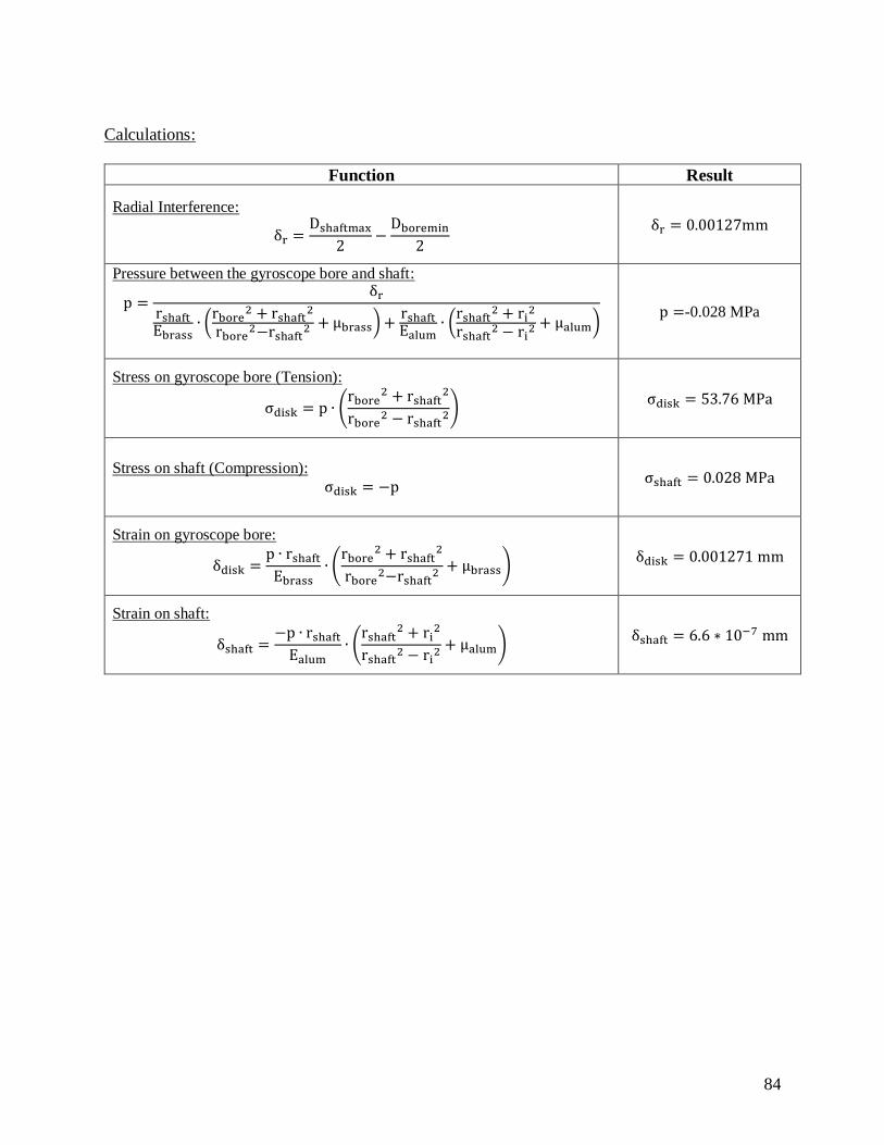
84
Calculations:
Function Result
Radial Interference:
δr =Dshaftmax
2−
Dboremin
2
δr = 0.00127mm
Pressure between the gyroscope bore and shaft:
p =δr
rshaftEbrass
∙ (rbore
2 + rshaft2
rbore2−rshaft
2 + μbrass) +rshaftEalum
∙ (rshaft
2 + ri2
rshaft2 − ri
2 + μalum)
p =-0.028 MPa
Stress on gyroscope bore (Tension):
σdisk = p ∙ (rbore
2 + rshaft2
rbore2 − rshaft
2) σdisk = 53.76 MPa
Stress on shaft (Compression):
σdisk = −p σshaft = 0.028 MPa
Strain on gyroscope bore:
δdisk =p ∙ rshaft
Ebrass∙ (
rbore2 + rshaft
2
rbore2−rshaft
2 + μbrass) δdisk = 0.001271 mm
Strain on shaft:
δshaft =−p ∙ rshaft
Ealum∙ (
rshaft2 + ri
2
rshaft2 − ri
2 + μalum) δshaft = 6.6 ∗ 10−7 mm
85
APPENDIX C: SHRINK FIT PROCESS
The gyroscope disk is uniformly heated in a convection oven to a temperature of 260 C
(500 F) for at least two hours. At the same time, the motor shaft is cooled in a freezer to at least
below 0 C (32 F). A plastic bag with a desiccant is used to contain the motor to prevent moisture
from entering the internal windings. Two tubes of 1 in aluminum tubing in parallel act as a
platform. Aluminum is used because it is a low-cost sturdy material. The objective is to insert the
motor shaft into the bore, rather than vice versa. The reason behind this is it is easier to control
the assembly with a lighter component than hold a hot brass disk. Once the hot disk is removed
from the oven, it is inverted and placed on top of the aluminum tubing as shown in Figure 44.
FIGURE 44: ALUMINUM TUBES SUPPORTING THE BRASS GYROSCOPE DISK
The bore is aligned with the spacing between the tubing and the cavity of the disk faces
up as shown in Figure 45.

86
FIGURE 45:CROSS SECTION OF THE DISK PLACEMENT
The spacing between the tubing is equal if not larger than the diameter of the shaft.
Therefore, when the shaft is inserted, the shaft will not contact the platform. The motor is
removed from the freezer and mounted to a platform using screws. This platform is be
maneuverable as once the motor is mounted, the platform will be held upside down. The bore
and the shafts are aligned and holding the inverted motor platform, the interference is made by
pushing the motor shaft down into the bore as positioned in Figure 46 and completed in Figure
47.
87
FIGURE 46: MOTOR SCREWED TO A PLATE AND ALIGNED WITH THE DISK BORE
FIGURE 47: MOTOR SHAFT INSERTED INTO THE DISK BORE
Figure 48 shows the cross section of the complete assembly. Should there be resistance,
the motor platform is lightly tapped down until the shaft is completely in. There may be some
steam and smoke during contact, possibly due to the coating on the motor. Ideally, levels should
be used on the aluminum platform and the motor platform to ensure the disk is axially aligned to
the shaft and not at an angle. Once the shaft is in its desired position, the assembly is let to

88
acclimate to room temperature, or is safe to touch. The disk has been successfully mounted to the
shaft.
FIGURE 48: CROSS SECTION DEPICTING THE COMPLETE ASSEMBLY

89
APPENDIX D: LEVER ARM TEST PROCEDURE
The theory behind this test is that a gyroscope has resistance to its changes in motion. By
mounting the gyroscope to a pivoting lever arm or pendulum, we can analyze the changes in
motion caused by the gyroscope at different angular speeds. This test requires a test contraption
that allows for the gyroscope assembly to be attached to a pendulum.
Required Materials:
• Pendulum Rig
• Gyroscope Prototype
• GoPro 7 (High Speed Camera)
• DSC-4783 Tripod
• Adobe Premiere Pro
• Poster with Marked Angles of Rotation
Setup:
1. Attach the gyroscope hand assembly to the end of the lever arm.
2. Position poster behind the pendulum and sketch angles of rotation for visualization
3. Set camera to record at 240 frames per second (fps)
Procedure:
1. Position the pendulum at a 5 degrees with the gyroscope turned off.
2. Record the rotation of the pendulum with the camera.
3. After the pendulum swings, stop the recording.
4. Repeat steps 1-3, running different trials with different angles, the gyroscope at various
motor speeds with at least 3 trials per each change in independent variable.
• Angles 5, 10, 15, 20 degrees
• Effect of gyroscope enabled on pendulum, disabled on pendulum
i. 6000 rpm
ii. 10000 rpm
iii. 14000 rpm
iv. 18000 rpm
5. Compile this data in a spreadsheet and create a relationship of “Swing Time of the
Pendulum as a Function of Motor RPM”
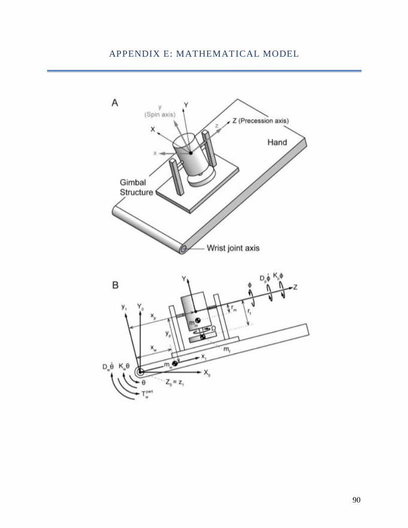
90
APPENDIX E: MATHEMATICAL MODEL

91
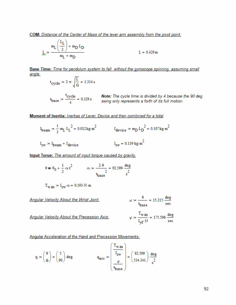
92
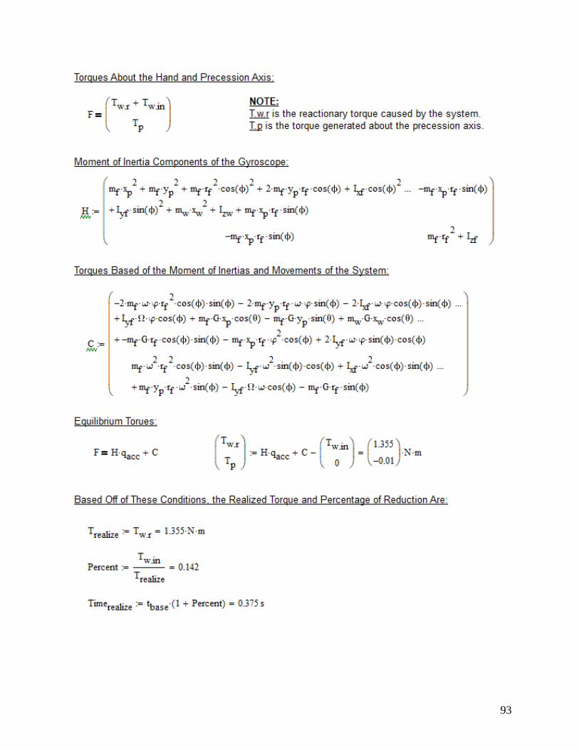
93
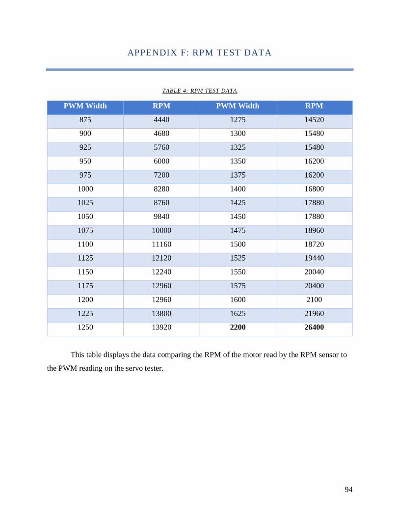
94
APPENDIX F: RPM TEST DATA
TABLE 4: RPM TEST DATA
PWM Width RPM PWM Width RPM
875 4440 1275 14520
900 4680 1300 15480
925 5760 1325 15480
950 6000 1350 16200
975 7200 1375 16200
1000 8280 1400 16800
1025 8760 1425 17880
1050 9840 1450 17880
1075 10000 1475 18960
1100 11160 1500 18720
1125 12120 1525 19440
1150 12240 1550 20040
1175 12960 1575 20400
1200 12960 1600 2100
1225 13800 1625 21960
1250 13920 2200 26400
This table displays the data comparing the RPM of the motor read by the RPM sensor to
the PWM reading on the servo tester.
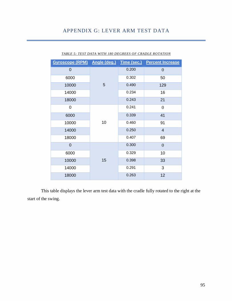
95
APPENDIX G: LEVER ARM TEST DATA
TABLE 5: TEST DATA WITH 180 DEGREES OF CRADLE ROTATION
Gyroscope (RPM) Angle (deg.) Time (sec.) Percent Increase
0
5
0.200 0
6000 0.302 50
10000 0.490 129
14000 0.234 16
18000 0.243 21
0
10
0.241 0
6000 0.339 41
10000 0.460 91
14000 0.250 4
18000 0.407 69
0
15
0.300 0
6000 0.329 10
10000 0.398 33
14000 0.291 3
18000 0.263 12
This table displays the lever arm test data with the cradle fully rotated to the right at the
start of the swing.
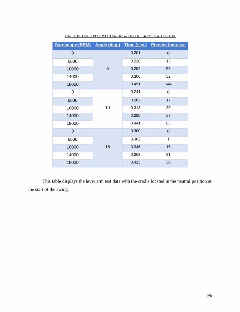
96
TABLE 6: TEST DATA WITH 90 DEGREES OF CRADLE ROTATION
Gyroscope (RPM) Angle (deg.) Time (sec.) Percent Increase
0
5
0.201 0
6000 0.228 13
10000 0.292 56
14000 0.306 52
18000 0.491 144
0
10
0.241 0
6000 0.282 17
10000 0.313 30
14000 0.380 57
18000 0.441 83
0
15
0.300 0
6000 0.302 1
10000 0.346 15
14000 0.363 21
18000 0.413 38
This table displays the lever arm test data with the cradle located in the neutral position at
the start of the swing.
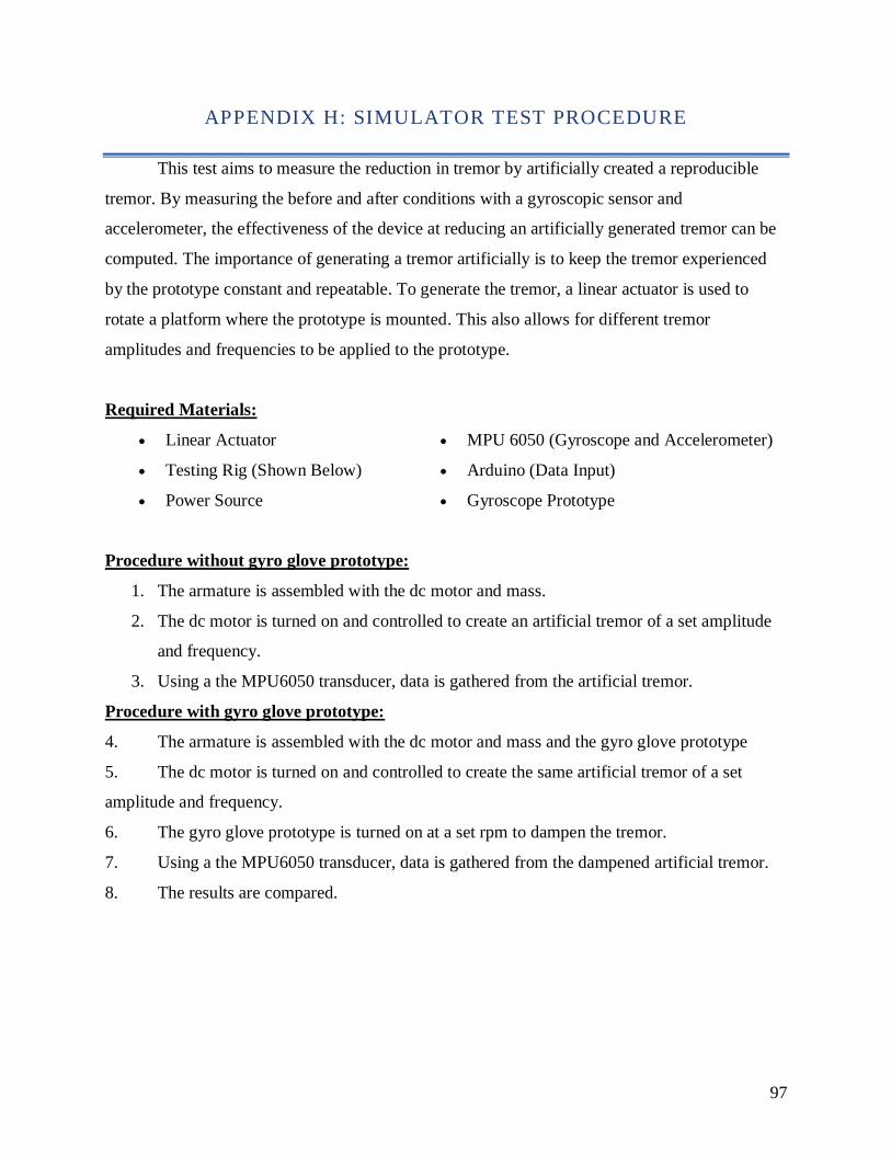
97
APPENDIX H: SIMULATOR TEST PROCEDURE
This test aims to measure the reduction in tremor by artificially created a reproducible
tremor. By measuring the before and after conditions with a gyroscopic sensor and
accelerometer, the effectiveness of the device at reducing an artificially generated tremor can be
computed. The importance of generating a tremor artificially is to keep the tremor experienced
by the prototype constant and repeatable. To generate the tremor, a linear actuator is used to
rotate a platform where the prototype is mounted. This also allows for different tremor
amplitudes and frequencies to be applied to the prototype.
Required Materials:
• Linear Actuator
• Testing Rig (Shown Below)
• Power Source
• MPU 6050 (Gyroscope and Accelerometer)
• Arduino (Data Input)
• Gyroscope Prototype
Procedure without gyro glove prototype:
1. The armature is assembled with the dc motor and mass.
2. The dc motor is turned on and controlled to create an artificial tremor of a set amplitude
and frequency.
3. Using a the MPU6050 transducer, data is gathered from the artificial tremor.
Procedure with gyro glove prototype:
4. The armature is assembled with the dc motor and mass and the gyro glove prototype
5. The dc motor is turned on and controlled to create the same artificial tremor of a set
amplitude and frequency.
6. The gyro glove prototype is turned on at a set rpm to dampen the tremor.
7. Using a the MPU6050 transducer, data is gathered from the dampened artificial tremor.
8. The results are compared.
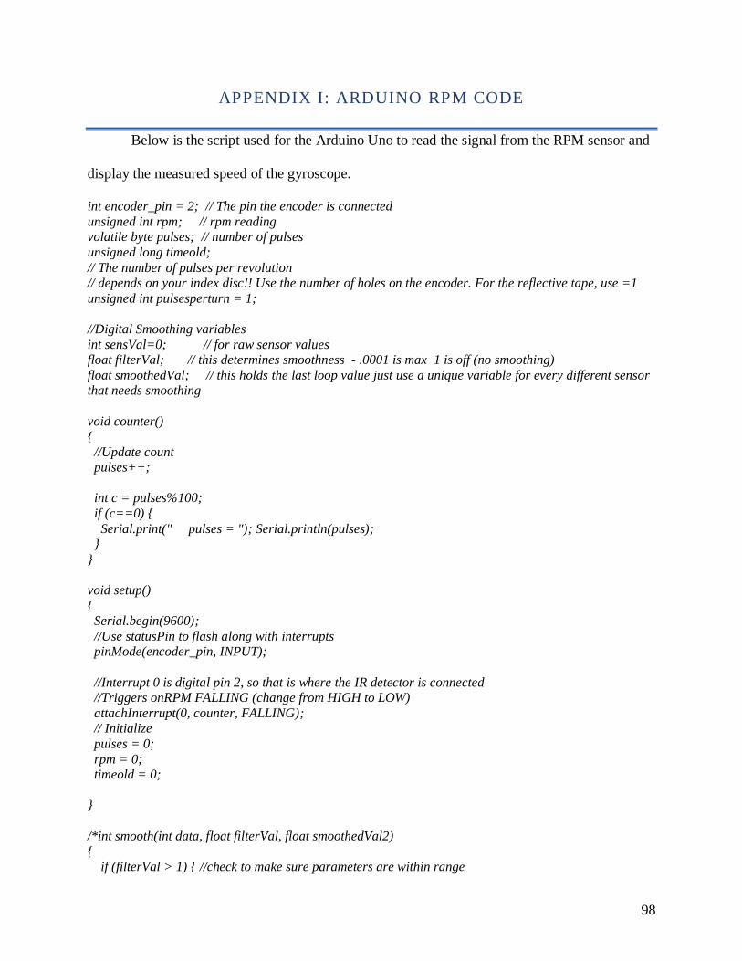
98
APPENDIX I: ARDUINO RPM CODE
Below is the script used for the Arduino Uno to read the signal from the RPM sensor and
display the measured speed of the gyroscope.
int encoder_pin = 2; // The pin the encoder is connected
unsigned int rpm; // rpm reading volatile byte pulses; // number of pulses
unsigned long timeold;
// The number of pulses per revolution // depends on your index disc!! Use the number of holes on the encoder. For the reflective tape, use =1
unsigned int pulsesperturn = 1;
//Digital Smoothing variables
int sensVal=0; // for raw sensor values float filterVal; // this determines smoothness - .0001 is max 1 is off (no smoothing)
float smoothedVal; // this holds the last loop value just use a unique variable for every different sensor that needs smoothing
void counter()
{
//Update count pulses++;
int c = pulses%100;
if (c==0) {
Serial.print(" pulses = "); Serial.println(pulses); }
}
void setup()
{ Serial.begin(9600);
//Use statusPin to flash along with interrupts pinMode(encoder_pin, INPUT);
//Interrupt 0 is digital pin 2, so that is where the IR detector is connected //Triggers onRPM FALLING (change from HIGH to LOW)
attachInterrupt(0, counter, FALLING);
// Initialize
pulses = 0;
rpm = 0; timeold = 0;
}
/*int smooth(int data, float filterVal, float smoothedVal2) {
if (filterVal > 1) { //check to make sure parameters are within range
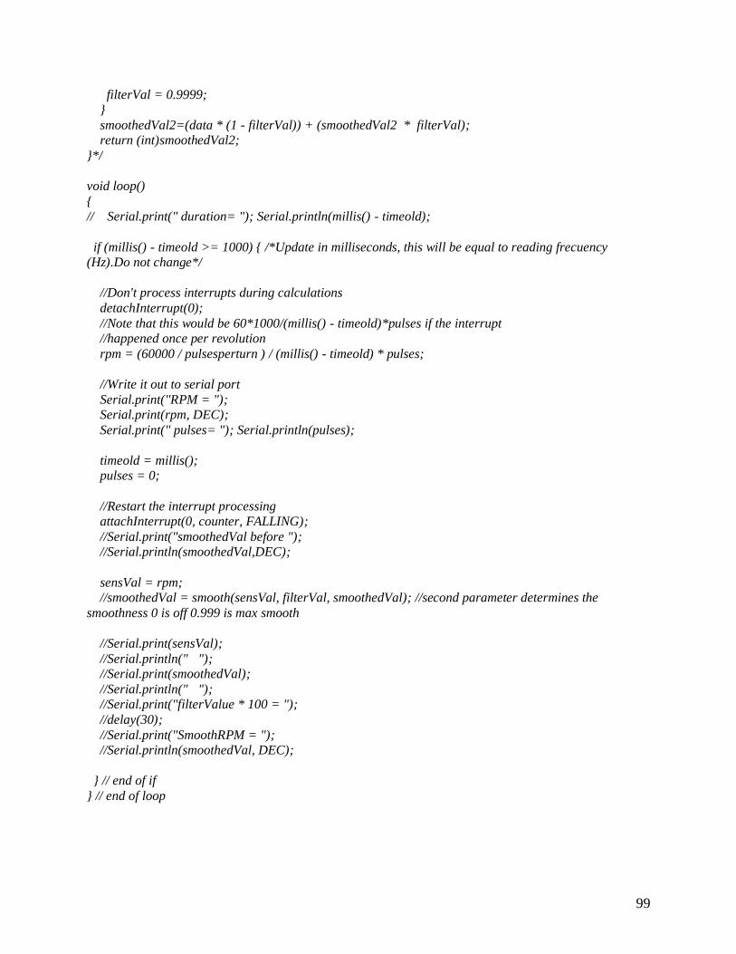
99
filterVal = 0.9999; }
smoothedVal2=(data * (1 - filterVal)) + (smoothedVal2 * filterVal);
return (int)smoothedVal2;
}*/
void loop()
{ // Serial.print(" duration= "); Serial.println(millis() - timeold);
if (millis() - timeold >= 1000) { /*Update in milliseconds, this will be equal to reading frecuency (Hz).Do not change*/
//Don't process interrupts during calculations
detachInterrupt(0);
//Note that this would be 60*1000/(millis() - timeold)*pulses if the interrupt
//happened once per revolution
rpm = (60000 / pulsesperturn ) / (millis() - timeold) * pulses;
//Write it out to serial port
Serial.print("RPM = "); Serial.print(rpm, DEC);
Serial.print(" pulses= "); Serial.println(pulses);
timeold = millis(); pulses = 0;
//Restart the interrupt processing attachInterrupt(0, counter, FALLING);
//Serial.print("smoothedVal before "); //Serial.println(smoothedVal,DEC);
sensVal = rpm; //smoothedVal = smooth(sensVal, filterVal, smoothedVal); //second parameter determines the
smoothness 0 is off 0.999 is max smooth
//Serial.print(sensVal);
//Serial.println(" "); //Serial.print(smoothedVal);
//Serial.println(" "); //Serial.print("filterValue * 100 = ");
//delay(30);
//Serial.print("SmoothRPM = "); //Serial.println(smoothedVal, DEC);
} // end of if
} // end of loop