gyroscope angular rate sensor three main types -...
TRANSCRIPT

Inertial SensorsInertial SensorsGyroscopes
• Gyroscope ⇔ Angular Rate Sensor• Three main types
Spinning Mass
Optical
• Ring Laser Gyros• Ring Laser Gyros
• Fiber Optic Gyros
Vibratory
• Coriolis Effect devices
– MEMS
4 March 2011 EE 570: Location and Navigation: Theory & Practice Lecture 6: Slide 1
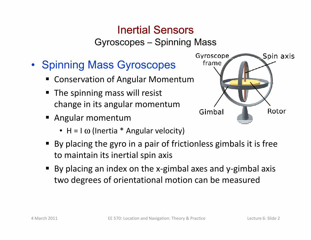
Inertial SensorsInertial SensorsGyroscopes – Spinning Mass
• Spinning Mass Gyroscopes Conservation of Angular Momentum
The spinning mass will resist
change in its angular momentum
Angular momentum Angular momentum
• H = I ω (Inertia * Angular velocity)
By placing the gyro in a pair of frictionless gimbals it is free
to maintain its inertial spin axis
By placing an index on the x-gimbal axes and y-gimbal axis
two degrees of orientational motion can be measured
4 March 2011 EE 570: Location and Navigation: Theory & Practice Lecture 6: Slide 2

Inertial SensorsInertial SensorsGyroscopes – Spinning Mass
• Precession Disk is spinning about z-axis
Apply a torque about the x-axis
Results in precession about the y-axis
• τ = ω × H
Hδ
H(t
)
ωdt
4 March 2011 EE 570: Location and Navigation: Theory & Practice Lecture 6: Slide 3
x
y
z
x
y
z
Precession
rate (ω)
ωdt

Inertial SensorsInertial SensorsGyroscopes - Optical
• Fiber Optical Gyro (FOG) Basic idea is that light travels at a
constant speed
If rotated (orthogonal to the plane)
one path length becomes longer and R
ω
one path length becomes longer and
the other shorter
This is known as the Sagnac effect
Measuring path length change (over
a dt) allows ω to be measured
4 March 2011 EE 570: Location and Navigation: Theory & Practice Lecture 6: Slide 4

Inertial SensorsInertial SensorsGyroscopes - Optical
• Fiber Optical Gyro (FOG) Measure the time difference betw
the CW and CCW paths
CW transit time = tCW
CCW transit time = tCCW
L = 2πR+Rωt = ct
Rω
LCW = 2πR+RωtCW = ctCW
LCCW = 2πR-RωtCCW = ctCCW
tCW = 2πR/(c-R ω)
tCCW= 2πR/(c+R ω)
With N turns
Phase
4 March 2011 EE 570: Location and Navigation: Theory & Practice Lecture 6: Slide 5
2
2
4 Rt
c
π ω⇒ ∆
2
4N At
c
ω∆
Splitter
0
0
82 2 /
c c
NAtf tc
c
π ωφ π π λ
λ≈ ∆ = ∆ =

Inertial SensorsInertial SensorsGyroscopes - Optical
• Ring Laser Gyro A helium-neon laser produces two
light beams, one traveling in the
CW direction and the other in the
CCW direction
When rotating
• The wavelength in dir of rotation
increases (decrease in freq)
• The wavelength in opposite dir
decreases (decrease in freq)
• Similarly, it can be shown that
4 March 2011 EE 570: Location and Navigation: Theory & Practice Lecture 6: Slide 6
0
4Af
ω
λ∆

Inertial SensorsInertial SensorsGyroscopes - Vibratory
• Vibratory Coriolis Angular Rate Sensor Virtually all MEMS gyros are based on this effect
ωω
4 March 2011 EE 570: Location and Navigation: Theory & Practice Lecture 6: Slide 7
2Corolis
a vω= × 2Corolis
a vω= ×

Inertial SensorsInertial SensorsGyroscopes - Vibratory
• Basic Planar Vibratory Gyro
Ω
4 March 2011 EE 570: Location and Navigation: Theory & Practice Lecture 6: Slide 8
Ω

Inertial SensorsInertial SensorsGyroscopes - Vibratory
• In plane sensing (left)• Out of plane sensing (right)
4 March 2011 EE 570: Location and Navigation: Theory & Practice Lecture 6: Slide 9
www.ett.bme.hu/memsedu

Inertial SensorsInertial SensorsSummarySummary
• Accelerometers Measure specific force of the body frame wrt the inertial
frame in the body frame coordinates
• Need to subtract the acceleration due to
gravity to obtain the motion induced quantity
b
ibf
In general, all points on a rigid body do NOT experience
the same linear velocity
• Gyroscopes Measure the inertial angular velocity
• Essentially, the rate of change of orientation
All points on a rigid body experience the
same angular velocity
4 March 2011 EE 570: Location and Navigation: Theory & Practice Lecture 6: Slide 10
b
ibω
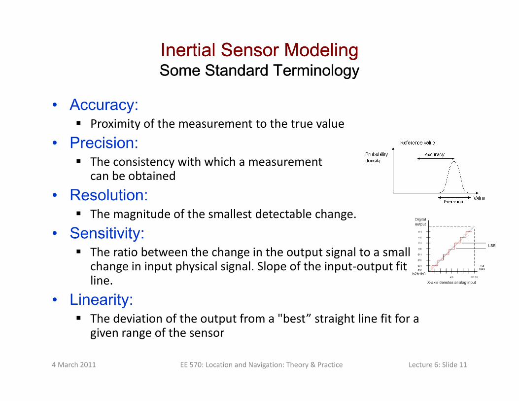
Inertial Sensor ModelingInertial Sensor ModelingSome Standard TerminologySome Standard Terminology
• Accuracy: Proximity of the measurement to the true value
• Precision: The consistency with which a measurement
can be obtained
• Resolution: • Resolution: The magnitude of the smallest detectable change.
• Sensitivity: The ratio between the change in the output signal to a small
change in input physical signal. Slope of the input-output fit line.
• Linearity: The deviation of the output from a "best” straight line fit for a
given range of the sensor
4 March 2011 EE 570: Location and Navigation: Theory & Practice Lecture 6: Slide 11

Inertial Sensor ModelingInertial Sensor ModelingAccuracy Accuracy vsvs PrecisionPrecision
Neither accurate nor precise
Accurate but not precise
4 March 2011 EE 570: Location and Navigation: Theory & Practice Lecture 6: Slide 12
Precise but not accurate Both accurate and precise

Inertial SensorsInertial SensorsInertial Sensor Error SourcesInertial Sensor Error Sources
• Bias – Often the most critical error source Fixed Bias
• Deterministic in nature and can be addressed by calibration
• Often modeled as a function of temperature
Bias Stability
FBb
BSb s FB BSb b b= + Bias Stability
• Varies from run-to-run as a random constant
Bias Instability
• In-run bias drift – Typically modeled as a random walk
4 March 2011 EE 570: Location and Navigation: Theory & Practice Lecture 6: Slide 13
Gyro bias errors are a major INS error source
BSb
BIb d BIb b=
, , ,a BI a FB a BS af b b b bδ = + + =
, , ,g BI g FB g BS gb b b bδω = + + =

Inertial SensorsInertial SensorsInertial Sensor Error SourcesInertial Sensor Error Sources
• Scale Factor Fixed Scale Factor Error
• Deterministic in nature and can be
addressed by calibration
• Often modeled as a function of temperature
Ref: Park, 04
Scale Factor Stability
• Varies from run-to-run as a random constant
• Typically given in parts-per-million (ppm)
4 March 2011 EE 570: Location and Navigation: Theory & Practice Lecture 6: Slide 14
The scale factor represents a linear approximation to the
steady-state sensor response over a given input range – True
sensor response may have some non-linear characteristics
Input
Ou
tpu
t
Scale Factor Error
af s fδ = asδω ω=

Inertial SensorsInertial SensorsInertial Sensor Error SourcesInertial Sensor Error Sources
• Misalignment Refers to the angular difference between the ideal sense
axis alignment and true sense axis vector
• A deterministic quantity typically given in milliradians
f m f m fδ = + m mδω ω ω= +
Combining Misalignment & Scale Factor
4 March 2011 EE 570: Location and Navigation: Theory & Practice Lecture 6: Slide 15
zxm
bx
by
bz
zym
Normalized z-sense axis, ,z a zx x a zy yf m f m fδ = +
, ,z g zx x g zy ym mδω ω ω= +
, , ,
, , ,
, , ,
a x a xy a xz x
b
a yx a y a yz y a ib
a zx a zy a z z
s m m f
f m s m f M f
m m s f
δ
= =

Inertial SensorsInertial SensorsInertial Sensor Error SourcesInertial Sensor Error Sources
• Cross-Axis Response Refers to the sensor output which occurs when the device
is presented with a stimulus which is vectorially orthogonal
to the sense axis
4 March 2011 EE 570: Location and Navigation: Theory & Practice Lecture 6: Slide 16
Misalignment and cross-axis response
are often difficult to distinguish –
Particularly during testing and
calibration activities

Inertial SensorsInertial SensorsInertial Sensor Error SourcesInertial Sensor Error Sources
• Other noise sources Typically characterized as additive in nature
• May have a compound form
– White noise
» Gyros: White noise in rate ⇒ Angle random walk
⇒» Accels: White noise in accel ⇒ Velocity random walk
– Quantization noise
» May be due to LSB resolution in ADC’s
– Flicker noise
– Colored noise
4 March 2011 EE 570: Location and Navigation: Theory & Practice Lecture 6: Slide 17
A more detailed discussion of noise
will be given at a later date (25 March)
Inertial SensorsInertial SensorsInertial Sensor Error SourcesInertial Sensor Error Sources
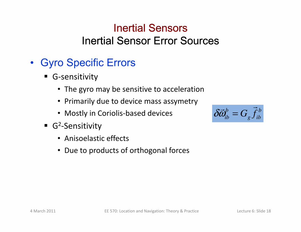
• Gyro Specific Errors G-sensitivity
• The gyro may be sensitive to acceleration
• Primarily due to device mass assymetry
• Mostly in Coriolis-based devicesb b
ib g ibG fδω =
• Mostly in Coriolis-based devices
G2-Sensitivity
• Anisoelastic effects
• Due to products of orthogonal forces
4 March 2011 EE 570: Location and Navigation: Theory & Practice Lecture 6: Slide 18
ib g ibG fδω =
Inertial SensorsInertial SensorsInertial Sensor Error SourcesInertial Sensor Error Sources
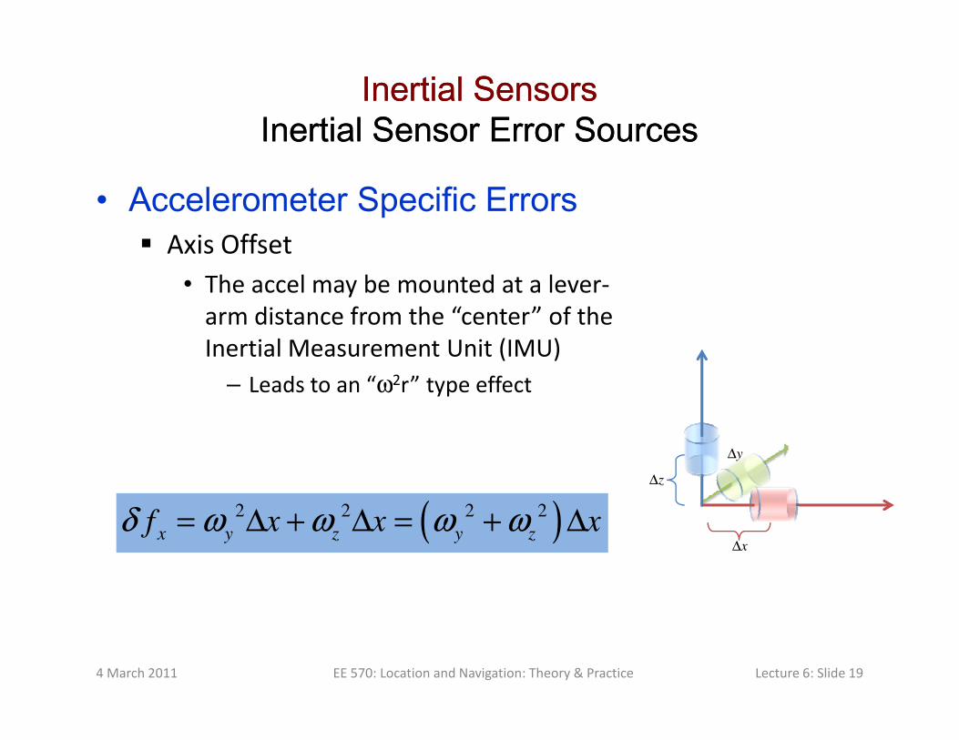
• Accelerometer Specific Errors Axis Offset
• The accel may be mounted at a lever-
arm distance from the “center” of the
Inertial Measurement Unit (IMU)
Leads to an “ω2r” type effect– Leads to an “ω2r” type effect
4 March 2011 EE 570: Location and Navigation: Theory & Practice Lecture 6: Slide 19
x∆
y∆
z∆
( )2 2 2 2
x y z y zf x x xδ ω ω ω ω= ∆ + ∆ = + ∆
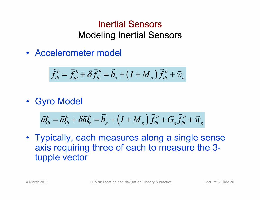
Inertial SensorsInertial SensorsModeling Inertial SensorsModeling Inertial Sensors
• Accelerometer model
• Gyro Model
( )b b b b
ib ib ib a a ib af f f b I M f wδ= + = + + +
• Gyro Model
• Typically, each measures along a single sense axis requiring three of each to measure the 3-tupple vector
4 March 2011 EE 570: Location and Navigation: Theory & Practice Lecture 6: Slide 20
( )b b b b b
ib ib ib g g ib g ib gb I M f G f wω ω δω= + = + + + +

Inertial SensorsInertial Sensors
• Current Accelerometer Application Areas
4 March 2011 EE 570: Location and Navigation: Theory & Practice Lecture 6: Slide 21
Ref: “INS/GPS Technology Trends“ by
George T. Schmidt RTO-EN-SET-116(2010)

Inertial SensorsInertial Sensors
• Current Gyro Application AreasEarth Rate
4 March 2011 EE 570: Location and Navigation: Theory & Practice Lecture 6: Slide 22
Ref: “INS/GPS Technology Trends“ by
George T. Schmidt RTO-EN-SET-116(2010)

Inertial SensorsInertial Sensors
Cost as a function of Performance and
technologyDifferent “Grades” of Inertial Sensors
4 March 2011 EE 570: Location and Navigation: Theory & Practice Lecture 6: Slide 23
Ref: INS Tutorial, Norwegian Space Centre, 2008.06.09