gujarat technological universitymytoolbag.in/media/gtupapers/1/2/civil/s3/som.pdf · concept of...
TRANSCRIPT


GUJARAT TECHNOLOGICAL UNIVERSITY STRENGTH of MATERIALS (Harmonized - PAI)
SUBJECT CODE: 2130608
B.E. 3RD SEMESTER (Harmonized - PAI)
Type of course: Applied Physics
Prerequisite: System of units
Laws of motion
Basic idea of force
Concept of centroid & Moment of Inertia
Fundamentals of stress, strain and their relationships
Rationale: This subject is conceptual applications of principles of mechanics of rigid and deformable
bodies in Engineering.
Teaching and Examination Scheme:
Teaching Scheme Credits Examination Marks
Total
Marks L T P C
Theory Marks Practical Marks
ESE
(E)
PA(M) PA(V) PA (I)
PA ALA ESE OEP
4 0 2 6 70 20 10 20 10 20 150
Sr.
No. Topics
Teaching
Hrs. Weightage
1 Statically Determinate Structures: Analysis of support reactions, Internal forces in trusses, beams;
Consideration of concentrated loads, moments/couples, Uniformly
Distributed Loads (UDL), Uniformly Varying Loads (UVL); Shear
Force and Bending Moment Diagrams for Beams, Point of
Contraflexures, Point and magnitude of Maximum bending moment
and maximum shear force,
08 20
2 Friction:
Theory of friction, Types of friction, Static and kinetic friction, Cone
of friction, Angle of repose, Coefficient of friction, Laws of friction,
Application of theory of friction: Friction on inclined plane, ladder
friction, wedge friction, belt and rope friction.
06 15
3 Stresses in Beams:
Flexural stresses – Theory of simple bending, Assumptions, derivation
of equation of bending, neutral axis, determination of bending stresses,
section modulus of rectangular & circular (solid & hollow), I,T,Angle,
channel sections
Shear stresses – Derivation of formula, shear stress distribution across
various beam sections like rectangular, circular, triangular, I, T, angle
sections.
08 20
4 Torsion: 06 15

Derivation of equation of torsion, Assumptions, application of theory
of torsion equation to solid & hollow circular shaft, torsional rigidity,
Power Transmitted by shaft.
5 Principal Stresses:
Two dimensional system, stress at a point on a plane, principal stresses
and principal planes, Mohr’s circle of stress 06 15
6 Physical & Mechanical properties of materials:
Elastic, homogeneous, isotropic materials; Stress –Strain relationships
for ductile and brittle materials, limits of elasticity and proportionality,
yield limit, ultimate strength, strain hardening, proof stress, factor of
safety, working stress, load factor, Properties related to axial, bending,
and torsional & shear loading, Toughness, hardness, Ductility,
Brittleness
06 15
Course Outcome: After learning the course the students should be able to:
1. Apply fundamental principles of mechanics & principles of equilibrium to simple and practical
problems of engineering.
2. Apply principles of statics to determine reactions & internal forces in statically determinate beams.
3. Determine centroid and moment of inertia of a different geometrical shape and able to understand its
importance.
4. Know basics of friction and its importance through simple applications.
5. Understand the different types of stresses and strains developed in the member subjected to axial,
bending, shear & torsional effects.
6. Know behaviour & properties of engineering materials.
List of Experiments: The students will have to solve at least five examples and related theory from each topic as an
assignment/tutorial. Students will have to perform following experiments in laboratory and prepare the
laboratory manual.
1. Verification of principle of moment: Bell crank lever
2. Determination of member force in a triangular truss
3. Determination of hardness of metals: Brinell /Vicker/Rockwell hardness test
4. Determination of impact of metals: Izod/Charpy impact test
5. Determination of Transverse strength and Modulus of Elasticity for Metals/Timber
6. Determination of Torsional strength and Modulus of Rigidity for Metals

Design based Problems (DP): (any two)
1. For a real industrial building having roof truss arrangement, (a) take photograph & identify type of
truss, (b) draw sketch of truss with all geometrical dimension, cross sections details, type of joints, type of
support conditions (c) prepare a model of truss (d) identify & determine types of load acts on it (d)
determine support reactions & member forces due to dead load & live load only.
2. Take a case of the Mery-Go-Round used in the fun park. Draw its sketch showing radius of wheel, no
of seats, capacity of each seats and other related information. Determine the amount of resultant produced
at the center of wheel during rest position, when (i) it is fully loaded (2) it is 30% loaded with symmetric
arrangement. Draw support arrangement and determine support reactions. Also determine amount of
torque required to start its operation.
3. Prepare working models for various types of beams with different shape of cross section, supporting
conditions and study the effect of cross section on the deflection of beams.
Major Equipment:
1. Truss set up
2. Bell crank lever
3. Hardness testing machine
4. Impact testing machine
5. Universal testing machine / Compression Testing Machine with Flexure Testing Arrangement
6. Torsion Testing Machine
List of Open Source Software/learning website:
www.nptel.iitm.ac.in/courses/
Active learning Assignments (AL) : Preparation of power-point slides, which include videos,
animations, pictures, graphics for better understanding theory and practical work – The faculty will
allocate chapters/ parts of chapters to groups of students so that the entire syllabus to be covered. The
Power-point slides should be put up on the web-site of the College/ Institute, along with the names of the
students of the group, the name of the faculty, Department and College on the first slide. The best three
works should submit to GTU.

1
Seat No.: ________ Enrolment No.___________
GUJARAT TECHNOLOGICAL UNIVERSITY BE - SEMESTER–III (NEW) - EXAMINATION – SUMMER 2017
Subject Code: 2130608 Date: 02/06/2017 Subject Name: Strength of Materials Time: 10:30 AM to 01:00 PM Total Marks: 70 Instructions:
1. Attempt all questions. 2. Make suitable assumptions wherever necessary. 3. Figures to the right indicate full marks.
MARKS
Q.1 Short Questions 14
1 Define Hardness of material. 01
2 Define Ultimate Strength of material. 01
3 Differentiate between ductility and malleability of
material.
01
4 Rupture Strength is a ratio of …………..to ………area.
01
5 According to Hook’s Law, Stress is directly proportional
to …………….
01
6 Load factor = (…………./………..) 01
7 Write the flexural formula of stress. 01
8 Coefficient of Static Friction µs =(… / Normal Reaction) 01
9 A simply supported beam subjected to udl ‘w’ in span
‘L’ , the maximum bending moment will be ……..
01
10 The stress in beam is lesser if its section modulus is….. 01
11 Shear Stresses on Principal Planes are……… 01
12 Distinguish between Static Friction and Kinetic Friction. 01
13 Method of Joint is used when forces in ……members are
required.
01
14 At neutral axis, the bending stress in beam is …….. 01
Q.2 (a) Explain different types of beam. 03
(b) Find reactions at supports A & B in fig(i). 04
(c) A block of mass 100 kg is placed on an incline plane as
shown in fig (ii). If µs = 0.35 and µk = 0.25 . determine
the force P required to (i) start the block to move up the
plane, (ii) to keep it moving up the plane , and
(iii) to prevent it from sliding down.
07
OR
(c) Determine the required diameter of the solid circular
shaft Subjected to torque of 10 kN m . The yield stress in
shear of the shaft material is 170MPa. Use a factor of
safety of 2.5.
07
Q.3 (a) What is Point of Contraflexure ? What is its significance? 03
(b) Draw a shear stress distribution over a Triangular
section.
04

2
(c) Draw the Shear Force and Bending Moment Diagram of
beam shown in fig (iii). 07
OR
Q.3 (a) A uniform steel rod, 6 mm diameter ( φ ) and 0.5 mm
long, is subjected to a tensile force of 3 KN. Find the
stress in the bar and its elongation. E = 200 GPa
03
(b) A hollow circular section, of the external diameter 200
mm and thickness 20mm, is to be used as beam. If the
maximum stress permissible in the material is 120MPa,
Find the maximum Bending Moment that this section can
carry.
04
(c) A bar of uniform cross section 20mm diameter is
subjected to loads as shown in fig (iv). Find the total
elongation of the bar and the maximum stress in the bar.
E=200GPa,( All lengths are in mm)
07
Q.4 (a) Write the assumption for Theory of torsion. 03
(b) If the maximum shear stress in material is limited to
60N/mm2 , Find the dimensions of as square section
subjected to an axial force of 200 KN.
04
(c) If compressive stress of 30MPa and tensile stress of 20
MPa are acting on an element. Determine the normal,
tangential and resultant stresses on a plane inclined at 25o
with the axis. Fig (v)
07
OR
Q.4 (a) Explain different types of Supports used in Structures. 03
(b) Draw a shear stress distribution over a Rectangular
section. 04
(c) Explain the Stress- Strain curve of Mild Steel. 07
Q.5 (a) State the Laws of Friction. 03
(b) Derive the equation for shear stress for beam in bending. 04
(c) A solid steel shaft of 60mm diameter is subjected to
torque of 5 KN-m at the free end as shown in fig (vi).
Determine the (i) Maximum shear stress developed in the
shaft (ii) the angular twist for 1 m length of shaft. Take
G= 80GPa.
07
OR
Q.5 (a) Define section modulus and its importance in bending. 03
(b) What are the assumptions made while derive the equation
of bending. 04
(c) A mild steel bar having cross section of 20mm X 40mm
and length of 400mm is subjected to an axial tensile load
of 100KN. Calculate the change in its dimensions and the
volumetric strain. Take E= 200 GPa and poisson ratio of
the material , µ = 0.3
07

3

Seat No.: ________ Enrolment No.___________
GUJARAT TECHNOLOGICAL UNIVERSITY BE - SEMESTER–III(New) • EXAMINATION – WINTER 2016
Subject Code:2130608 Date:04/01/2017
Subject Name:Strength of Materials
Time: 10:30 AM to 01:00 PM Total Marks: 70 Instructions:
1. Attempt all questions.
2. Make suitable assumptions wherever necessary.
3. Figures to the right indicate full marks.
Q.1 (a) Short Questions 07
1 Shear stress in surface fiber of a circular shaft in torsion is:
(a) Minimum (b) Zero (c) Maximum (d) none of these.
2 Maximum stress on a principle plane is :
(a) Tangential stress (b) shear stress (c) normal stress (d) none of these.
3 A beam/cantilever is simple (pure) bending has:
(a) No bending moment (b) No shear force (c) Varying bending moment
(d) Varying shear force.
4 The number of principal planes in any combination of applied stress always is:
(a) 1 (b) 2 (c) 3 (d) 4.
5 Strength of beam is more if its section modulus is:
(a) Decreased (b) Zero (c) Increased (d) None of these.
6 At the point of inflexion (contra flexure) we have:
(a) Zero shear force (b) zero bending moment (c) Maximum bending moment
(d) Maximum shear moment.
7 A material having identical properties in all directions, is called,
(a) Elastic (b) homogeneous (c) isotropic (d) all the above.
(b) Define:
(1) Hardness (2) Toughness (3) Ductility (4) Brittleness (5) Factor of safety
(6) Ultimate strength (7) Working stress.
07
Q.2 (a) Explain the sign convention taken to compute Shear force and Bending moment 03
(a) Draw shear stress distribution diagram for the following section,
(1) Rectangular section (2)Circular section (3) I section (4) T section. 04
(b) What power can be transmitted by a hollow circular shaft of 10cm outer diameter
and 8cm inside diameter while rotating at 150 rpm if the maximum permissible
shear stress is 60MN/m2 and the maximum torque is 1.3 times the mean torque?
07
OR
(b) A circular log of timber has diameter D. find the dimensions of the strongest
rectangular section to resist moment, one can cut from this log. 07
Q.3 (a) Explain the principal planes, principal stresses and natural axis. 03
(b) A simply supported beam is shown in fig Q-3(b) of span 5m has a cross-section
150mm ×250mm .if the permissible stress is10N/mm2,find(a) Maximum intensity of
u.d.l it can carry.
04
(c) Derive the Torsion equation with usual notations.
07
OR
Q.3 (a) Explain in simple theory of bending. 03
(b) Write short note on (i) working stress (ii) load factor (iii) strain hardening.
04
(c) At a point in a strained material there is tensile stress of 80N/mm2 upon a horizontal
plane and a compressive stress of 40N/mm2 upon a vertical plane There is also a
shear stress of 48N/mm2 upon each of these planes in fig Q-3 ©Determine the
07

planes of maximum shear stress at the point. Determine also the resultant stress on
the planes of maximum shear stress.
Q.4 (a) Write short note on Torsion rigidity. 03
(b) Explain MOHR’S circle of stress? 04
(c) Draw the bending moment and shear force diagrams for the cantilever beam shown
in fig.Q-4©. 07
OR
Q.4 (a) Define: Friction and also explain ladder& wedge friction. 03
(b) Explain static and kinetic friction. 04
(c) A hollow propeller shaft of a steam ship is to transmit 3750kW at 240rpm.if thee
internal diameter is 0.8times the external diameter and if the maximum shear stress
developed is to be limited to 160 N/mm2,determine the size of the shaft.
07
Q.5 (a) Explain : (i) cone of friction (ii) coefficient of friction (iii) Laws of friction 03
(b) Prove with usual notations T1/T2=eµᶿ for belt friction. 04
(c) The cross-section of a beam is shown in fig Q-5© if permissible stress is 150
N/mm2, find its moment of resistance. Compare it with equivalent section of same
but (a) square section (b) rectangular section with depth twice the width and (c) a
circular section.
07
OR
Q.5 (a) Explain element subjected to general two dimensional stress system. 03
(b) Prove with usual notation the maximum shear stress for a rectangular section is 1.5
times the average shear stress. 04
(c) State assumptions made in the theory of pure bending. Derive the equation of
bending stress distribution across the cross section in a beam subjected to general
loading.
07
*************

Seat No.: ________ Enrolment No.___________
GUJARAT TECHNOLOGICAL UNIVERSITY
BE - SEMESTER–III(New) EXAMINATION – SUMMER 2016
Subject Code:2130608 Date:09/06/2016
Subject Name:Strength of Materials Time:10:30 AM to 01:00 PM Total Marks: 70 Instructions:
1. Attempt all questions.
2. Make suitable assumptions wherever necessary. 3. Figures to the right indicate full marks.
Q.1 (a) Short Questions 07
1 The ratio of limiting friction and normal reaction is known as (a)coefficient of friction (b)angle of friction (c)angle of repose (d)slidingfriction
2 The necessary condition for forces to be in equilibrium is that these should be
(a)coplanar (b) meet at onepoint; (c) both (a) and (b) above (d) all be equal
3 A body moves, from rest with a constant acceleration of 5 m per sec. The distance covered in 5 sec is most nearly (a)38m (b)62.5m (C)96m (d)124m
4 A heavy ladder resting on floor and against a vertical wall may not be in
equilibrium, if (a)the floor is smooth,the wall rough (b) the floor is rough, the wall is smooth (c)the floor and wall both are smooth surfaces (d) the floor and wall both are rough sur-faces
5 According to principle of transmissibility of forces,the effect of a force upon a body is (a)maximum when it act at the center of gravity of a body (b)different at different points in its line of action (c)the same at every point in its line of action (d)minimum when it acts at the C.G. of the body
6 The units of moment of inertia of an area are (a)kgm2 (b) m4 (c) kg/m2 (d) m3
7 In actual machines (a)mechanical advantage is greater than velocity ratio (b)mechanical advantage is equal to velocity ratio (c)mechanical advantage is less than velocity ratio (d) mechanical advantage is unity
(b) Define: (i) elastic body(ii) plastic body(iii)rigid body (iv) deformation (v)Hardness (vi)Toughness (vii) Ductility
07
Q.2 (a) Explain the sign convention taken to compute Shear force and Bending moment 03
(b) Draw shear stress distribution diagram for the following section,
(1) Rectangular section (2)Circular section (3) I section (4) T section. 04
(c) What power can be transmitted by a hollow circular shaft of 10cm outer diameter
and 8cm inside diameter while rotating at 150 rpm if the maximum permissible
shear stress is 60MN/m2 and the maximum torque is 1.3 times the mean torque?
07
OR
(c) A circular log of timber has diameter D. find the dimensions of the strongest
rectangular section to resist moment, one can cut from this log. 07
Q.3 (a) Explain the principal planes, principal stresses and natural axis. 03
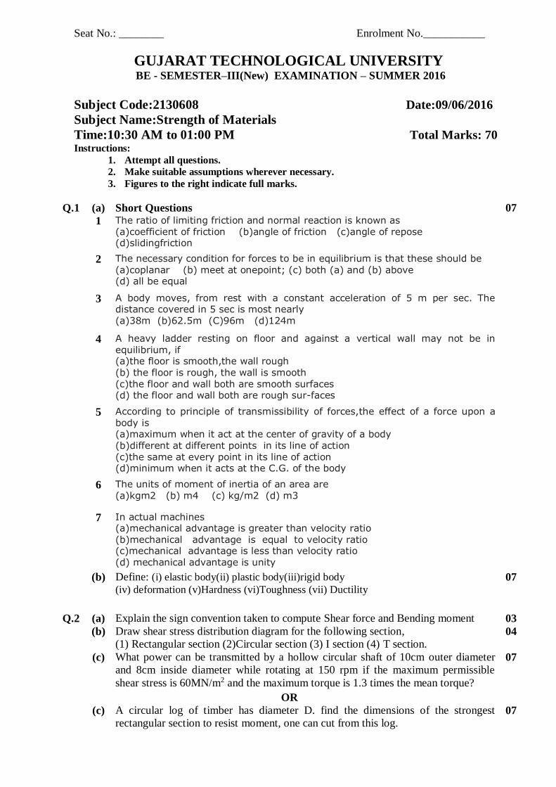
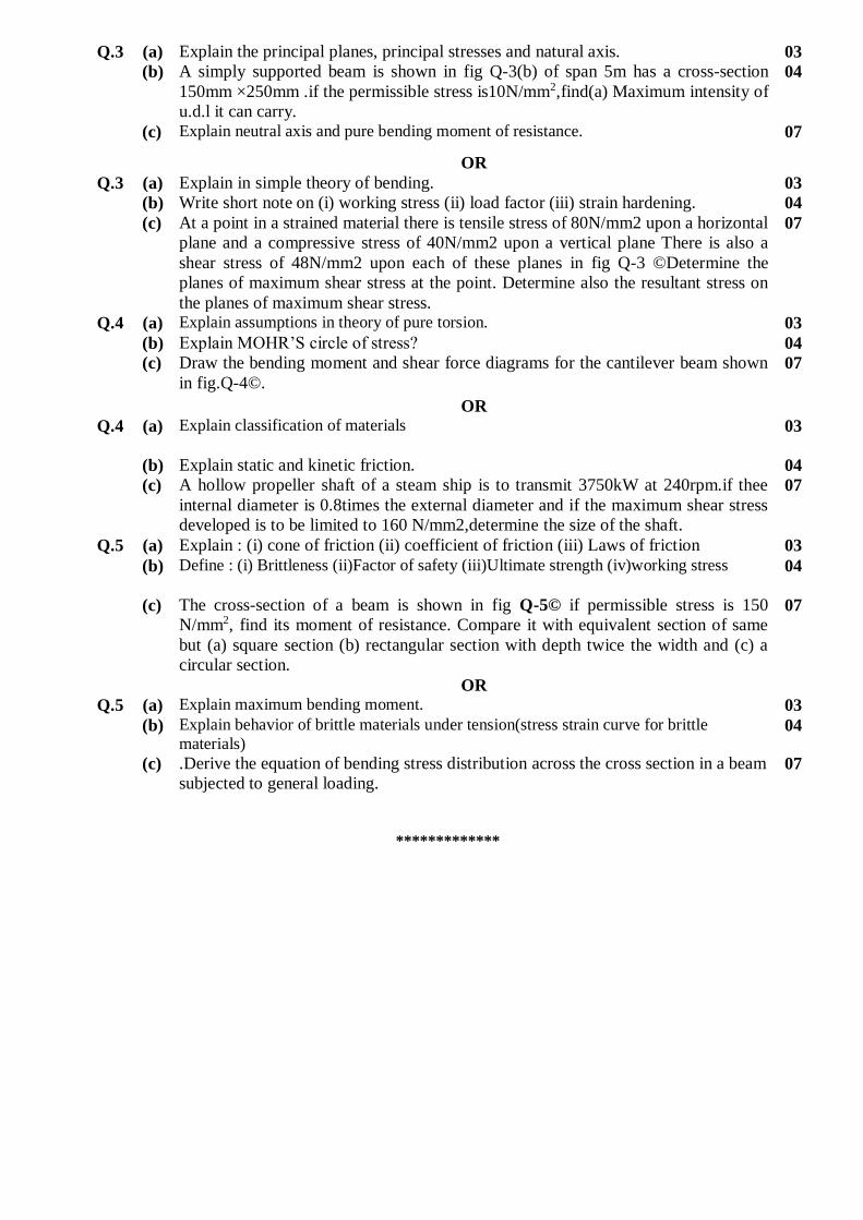
(b) A simply supported beam is shown in fig Q-3(b) of span 5m has a cross-section
150mm ×250mm .if the permissible stress is10N/mm2,find(a) Maximum intensity of
u.d.l it can carry.
04
(c) Explain neutral axis and pure bending moment of resistance. 07
OR
Q.3 (a) Explain in simple theory of bending. 03
(b) Write short note on (i) working stress (ii) load factor (iii) strain hardening. 04
(c) At a point in a strained material there is tensile stress of 80N/mm2 upon a horizontal
plane and a compressive stress of 40N/mm2 upon a vertical plane There is also a
shear stress of 48N/mm2 upon each of these planes in fig Q-3 ©Determine the
planes of maximum shear stress at the point. Determine also the resultant stress on
the planes of maximum shear stress.
07
Q.4 (a) Explain assumptions in theory of pure torsion. 03
(b) Explain MOHR’S circle of stress? 04
(c) Draw the bending moment and shear force diagrams for the cantilever beam shown
in fig.Q-4©.
07
OR
Q.4 (a) Explain classification of materials
03
(b) Explain static and kinetic friction. 04
(c) A hollow propeller shaft of a steam ship is to transmit 3750kW at 240rpm.if thee
internal diameter is 0.8times the external diameter and if the maximum shear stress
developed is to be limited to 160 N/mm2,determine the size of the shaft.
07
Q.5 (a) Explain : (i) cone of friction (ii) coefficient of friction (iii) Laws of friction 03
(b) Define : (i) Brittleness (ii)Factor of safety (iii)Ultimate strength (iv)working stress
04
(c) The cross-section of a beam is shown in fig Q-5© if permissible stress is 150
N/mm2, find its moment of resistance. Compare it with equivalent section of same
but (a) square section (b) rectangular section with depth twice the width and (c) a
circular section.
07
OR
Q.5 (a) Explain maximum bending moment. 03
(b) Explain behavior of brittle materials under tension(stress strain curve for brittle
materials) 04
(c) .Derive the equation of bending stress distribution across the cross section in a beam
subjected to general loading.
07
*************


1
Seat No.: ________ Enrolment No.___________
GUJARAT TECHNOLOGICAL UNIVERSITY BE - SEMESTER–III (New) EXAMINATION – WINTER 2015
Subject Code:2130608 Date:02/01/2016
Subject Name: STRENGTH OF MATERIAL
Time: 2:30pm to 5:00pm Total Marks: 70 Instructions:
1. Attempt all questions.
2. Make suitable assumptions wherever necessary.
3. Figures to the right indicate full marks.
MARKS
Q.1 Short Questions 14
1 The friction always acts in the direction.
(a) Of the force
(b) Opposite to the force
(c) Opposite to that in which the body tends to move
(d) Perpendicular to the force
2 The magnitude of the force of friction between two bodies, one
laying above the other depends upon the roughness of the
magnitude of the force of friction between two bodies, one laying
above the bodies, one laying above the
(a) Upper body (b) Lower body (c) Both the bodies
(d) The body having more roughness 3 A circular section shaft of dia. D(m) is used to transmit H
(kw) of power at N r.p.m. The maximum tensile stress(Mpa)
induced on the surface of the shaft is K.H/d³ N.K is for circular
shaft following
(a) 0.48 (b) 0.48π² (c) 0.48π (d) 0.48/π² 4 Two shafts of 20 mm dia. Each are connected by flange coupling
bolted by four bolts of 10 mm dia. Each and subjected to shearing
stress of 15 N/mm². The maximum shearing stress induced in shaft
is
(a) 15 N/mm² (b) 45 N/mm² (c) 60 N/mm² (d) 75 N/mm² 5 On a principal plane the magnitude of shear stress will be equal to
(a) Maximum (b) Minimum (c) Zero (d) Infinity

2
6 When a body is subjected to two tensile stresses of equal
magnitude on two mutually perpendicular planes, the radius of
Mohr circle will be
(a) Maximum (b) minimum (c) zero (d) infinity 7 If a body does not regain its original size and shape on removal of
an externally applied load and gets permanently deformed, it is
called a
(a) Elastic body (b) Plastic body (c) Rigid body (d) None of above 8 A material can not undergo any deformation under the action of
external loads and it fails by rapture , it is called
(a) Elastic material (b) Plastic material (c) Ductile material (d) Brittle material 9 As the elastic limit reaches, tensile strain
(a) Increases more rapidly
(b) Decreases more rapidly
(c) Increases in proportion to the stress
(d) Decreases in proportion to the stress
(e)
10 The materials which have the same elastic properties in all
directions, are called
(a) Isotropic
(b)
(b) Brittle
(c) Homogeneous
(d) Hard
11 When equal and opposite forces applied to a body, tend to
elongate , the stress so produced, is called
(a) shear stress
(e)
(b) compressive stress
(c) tensile stress
(d) transverse stress
12 A simply supported beam of span L carries a uniformly distributed
load W. The maximum bending moment M is
(a) WL/2
(f)
(b) WL/4
(c) WL/8
(d) WL/12
13 For a simply supported beam with a central load, the bending
moment is
(a) least at the centre
(g)
(b) least at the support
(c) maximum at the support
(d) maximum at the support
14 Simple bending equation is
(a) M/I=R/E=F/Y
(b) I/M=E/R=Y/F
(c) M/I=E/R=F/Y
(d) M/I=R/E=Y/F
(e)

3
Q.2 (a) Explain the sign convention taken to compute shear force and
bending moment.
03
(b) Derive relation between S.F. and B.M. in a beam subjected to
general loadind
04
(c) A cantilever of length 2m carries a UDL of 1.5KN/m run over the
whole length and a point load of 2 KN at a distance of 0.5m from
the free end. Calculate shear force and bending moments and plot
the S.F. and B.M. diagrams.
07
OR
(c) Draw shear force and bending moment diagram for the beam as
shown in figure 1.
07
Q.3 (a) Explain neutral axis and pure bending moment of resistance. 03
(b) Explain assumptions made in theory of pure bending. 04
(c) A simply supported beam of 4m span has a cross section
200mmX300mm. if the permissible stress in the material of the
beam is 20 N/mm². determine maximum udl it can carry.
07
OR
Q.3 (a) Explain maximum bending moment. 03
(b) Explain theory of pure bending 04
(c) A beam having an I section with top flange 80mX40m, web
120mX20mm and bottom flange 160mmX40mm, simply
supported over a span of 6m, is subjected to uniformly distributed
load over entire span. If bending stress is limited to 40
N/mm²tensile and 120 N/mm² compressive, find max. value of
U.D.L. the beam can carry if the larger flange is in tension.
07
Q.4 (a) Explain angle of friction. 03
(b) Define(i) elastic body(ii) plastic body(iii)rigid body
(iv) deformation
04
(c) A ladder 6m long rests on horizontal ground and leans
Against a smooth vertical wall at an angle of 20° with the vertical.
Its weight is 100N acting at its middle. It ison the point of sliding
when a man weighing 500N stands on it at a distance 2.2m along
the ladder from foot of ladder.
Calculate coefficient of friction.
07
OR
Q.4 (a) Explain classification of materials. 03
(b) Explain behavior of brittle materials under tension(stress strain
curve for brittle materials)
04
(c) A 4m long ladder has to carry a person of 75kg weight at 3.5 m
distance from floor, along the length of ladder. The self weight of
ladder is of 150N. find the maximum distance of lower end of
ladder from vertical wall so that it does not slide. The coefficient of
friction between floor and ladder is 0.3 and that between vertical
wall and ladder is 0.2.
07
Q.5 (a) Explain principal plane and principal stress and neutral axis. 03
(b) Explain assumptions in theory of pure torsion. 04
(c) A hollow circular shaft of 150mm external diameter and 100mm
internal diameter is subjected to a torque of 5 kN.m. find maximum
shear stress and shear stress at the internal surface of the shaft.
07

4
Also, calculate the angle of twist for 2.0 m long shaft, if modulus
of rigidity is 100GPa.
OR
Q.5 (a) Explain torsional stiffness and power transmitted. 03
(b) Explain polar modulus. 04
(c) The shear and normal stresses on a cross section of a beam as
shown in figure 2. Find the principal stresses and direction of
principal planes.
07
Figure 1
Figure 2

Seat No.: ________ Enrolment No.___________
GUJARAT TECHNOLOGICAL UNIVERSITY BE - SEMESTER– III EXAMINATION – SUMMER 2015
Subject Code:2130608 Date:09/06/2015 Subject Name: Strength of materials Time: 02:30pm to 05:00 pm Total Marks: 70 Instructions:
1. Attempt all questions. 2. Make suitable assumptions wherever necessary. 3. Figures to the right indicate full marks.
Q 1(a) State assumptions made in the theory of pure bending. Derive the equation of bending stress distribution across the cross section in a beam subjected to general loading.
07
(b) Calculate shear force and bending moment at salient points of the beam as shown in figure 1and also draw shear force and bending moment diagram for the beam .
07
Q 2 (a) A rolled I section has the dimension as shown in Figure 2 .This beam of I section
carries a UDL of 40 KN/m run on a span of 10 m,Calculate the maximum stress produced due to bending.
07
(b) Derive the Torsion Equation. 07 OR (b) A cantilever of length 2 m carries a UDL of 1.5 KN/m run over the whole length
and a point load of 2 KN at a distance of 0.5 m from the free end. Calculate shear force and bending moments and plot the S.F and B.M diagrams.
07
Q 3 (a) Derive the relation between S.F and B.M in a beam subjected to general loading. 04 (b) Explain the sign convention taken to compute Shear force and Bending moment. 03 (c) Obtain an expression for the major and minor principal stresses on a plane, when
the body is subjected to direct stresses in two mutually perpendicular directions accompanied by a shear stress.
07
OR Q 3 (a) A block of 10 N weight rest on a rough inclined plane. The inclination of plane
with horizontal is 30°.If coefficient of friction is 0.25. Calculate the force that is to be applied parallel to move the block upwards.
07
(b) A solid shaft of 120 mm diameter is required to transmit 200 KW at 100 rpm.If the angle of twist not to exceed 2°.Find the length of the shaft .Take modulus of rigidity for the shaft material as 90 GPa.
07
Q 4 (a) A simply supported wooden beam of span 1.3 m having a cross section 150 mm
wide by 250 mm deep carries a point load of W at the centre. The permissible stress are 7 N/ mm2 in bending and 1 N/ mm2 in shearing. Calculate the safe load W.
07
(b) Explain the law of static friction and law of dynamic friction. Also define (1) angle of friction (2) angle of repose (3) coefficient of friction.
07
OR Q 4 (a) Determine the diameter of shaft which will transmit 100 KW at 150 rpm.If 07

maximum shearing stress is limited to 50 N/ mm2. (b) Draw shear stress distribution diagram for the following section
(1)Rectangular section (2)Circular section (3) I section (4)T section 04
(c) Explain the principal planes principal stresses and natural axis. 03
Q 5 (a) A simply supported beam of 4 m span carries a point load of W at 1 m from one support. Find the value of this load so that maximum bending stress in tension and compression are limited to 100 MPa and 80 MPa respectively. The cross section of the beam is a Tee section as shown in figure 3 with top flange in compression.
07
(b) Define (1)Hardness (2)Toughness (3) Ductility (4) Brittleness (5)Factor of safety (6)Ultimate strength (7)working stress
07
OR Q 5 (a) Draw the shear force and bending moment diagrams for the beam as shown in
figure 4. 07
(b) The stresses at a point in a bar are 200 MPa (tensile) and 100 MPa (compressive).Determine the resultant stress in magnitude and Direction on a plane inclined at 60°. to the axis of the major stress.
07
Figure 1 Oue 1 (a) Figure 2 Que 2 (a) (web thickness is 10 mm)
Figure 3 Que 5 (a) Figure 4 Que 5 (a)or *************

1
Seat No.: ________ Enrolment No.___________
GUJARAT TECHNOLOGICAL UNIVERSITY BE - SEMESTER–III • EXAMINATION – WINTER • 2014
Subject Code: 2130608 Date: 26-12-2014
Subject Name: Strength of Materials
Time: 02.30 pm - 05.00 pm Total Marks: 70 Instructions:
1. Attempt all questions.
2. Make suitable assumptions wherever necessary.
3. Figures to the right indicate full marks.
Q.1 (a) Select the appropriate answer from given options and rewrite the complete sentence.
(1)When shear force at a point is zero,then bending moment at that point will be
(a)Zero
(b)Maximum
(c) Minimum
(d)Infinity
(2)At fixed support, the possible reactions are
(a)Vertical (V) only
(b)Horizontal (H) only
(c) Moment (M) only
(d) V,H,M all
(3)The force of friction between two bodies in contact
(a)Depends on the area of their contact
(b)Depends on the roughness of the surfaces
(c) Depends on the relative velocity between them
(d) All of the above
(4)At neutral axis bending stress is
(a)Minimum
(b)Maximum
(c) Zero
(d)Infinity
(5)For any section shear stress at the top edge is
(a)Maximum
(b)Minimum
(c) Zero
(d)Infinity
(6)When a body is subjected to two tensile stresses of equal magnitude on two
mutually perpendicular planes, the radius of Mohr’s circle will be
(a)Zero
(b)Maximum
(c) Minimum
(d) Infinity
(7) The materials which have the same elastic properties in all directions are
(a)Isotropic
(b)Brittle
(c) Homogeneous
(d) Hard.
07
(b) Define the following terms.
(1) Hardness (2) Brittleness (3) Ductility (4) Malleability
(5) Elasticity (6) Strength (7) Toughness.
07
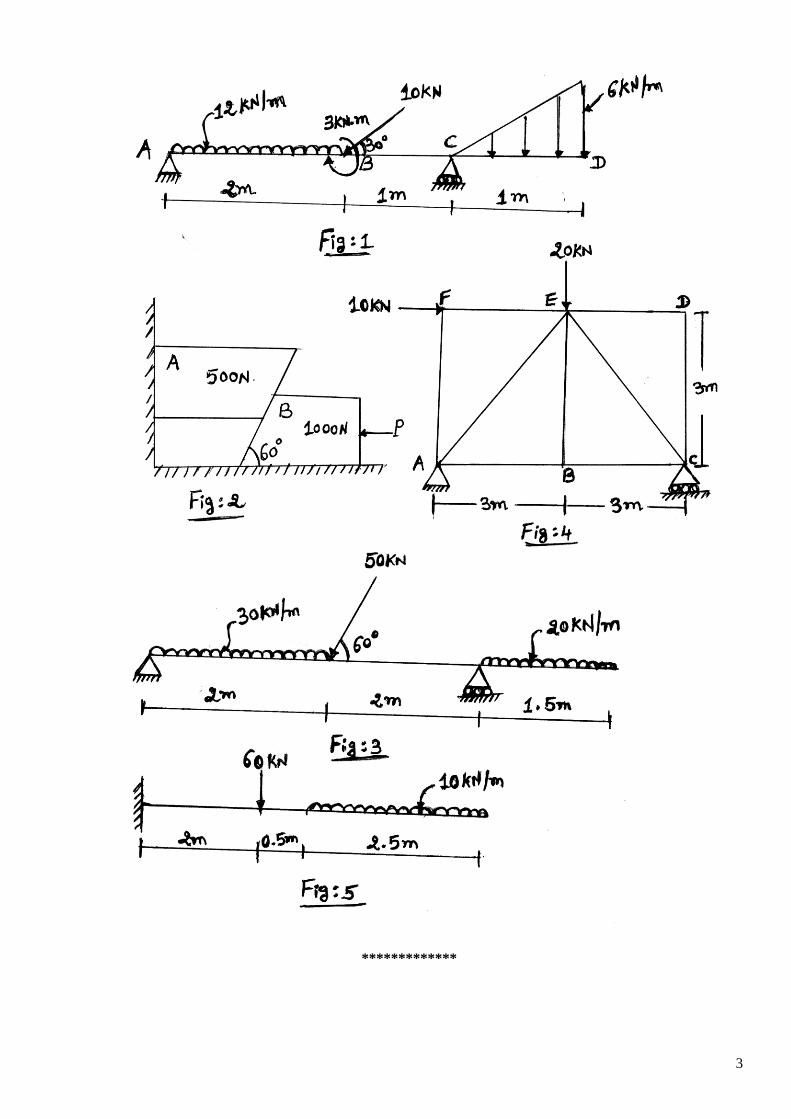
Q.2 (a) A simply supported overhanging beam ABCD is loaded as shown in Fig:1. Calculate 07

2
shear force and bending moments at salient points and plot shear force and bending
moment diagrams. Also locate point of contraflexure from support A.
(b) A ladder 7 m long rests against a vertical wall with which it makes an angle of 450
and resting on a floor. If a man whose weight is one half of that the ladder, climbs it.
At what distance along the ladder will he be when ladder is about to slip?µs = 1/3 at
wall and 1/2 at floor.
07
OR
(b) Two blocks A and B are resting against a wall and the floor as shown in Fig:2. Find
horizontal force P applied to the lower block that will hold the system in equilibrium.
Take µ = 0.25 at floor, µ = 0.3 at wall and µ = 0.2 between the blocks.
07
Q.3 (a) Find support reactions for the beam shown in Fig:3. 07
(b) Prove with usual notations = for belt friction.
07
OR
Q.3 (a) Calculate member forces in simply supported truss shown in Fig:4. 07
(b) Draw shear force and bending moment diagrams for the beam shown in Fig:5. 07
Q.4 (a)
Prove with usual notations . 07
(b) A circular pipe of external diameter 70 mm and thickness 8 mm is used as a simply
supported beam over an effective span of 2.5 m. Find the maximum concentrated load
that can be applied at the centre of the span if permissible stress in the tube is 150
MPa.
07
OR
Q.4 (a) Prove with usual notation the maximum shear stress for a rectangular section is 1.5
times the average shear stress.
07
(b) A beam of I section, 50 cm deep and 20 cm wide, has equal flanges 2 cm thick and
web 1 cm thick. It carries a shear force of 100 kN at its cross section. Determine the
shear stress distribution in the beam and the ratio of maximum shear to mean shear.
Show the values with the help of neat sketch.
07
Q.5 (a) Derive the Torsion equation with usual notations. 07
(b) A hollow shaft of internal diameter 150 mm and external diameter 250 mm is
subjected to a torque of 200 kN.m. Determine the maximum shear stress developed.
Determine the power transmitted by this shaft if it runs at 200 rpm. If the modulus of
rigidity is 80 GPa, find the shear stress developed at a point on the internal (diameter)
periphery of the shaft.
07
OR
Q.5 (a) At a point in a strained material the principal stresses are 100 N/mm2
(tensile) and 60
N/mm2 (compressive). Determine analytically normal stress, shear stress and resultant
stress on a plane inclined at 500 to the axis of major principal stress.
07
(b) At a point in a strained material the normal tensile stress are 60 N/mm2 and 30
N/mm2. Determine by Mohr's circle, the resultant intensity of stress on a plane
inclined at 400 to the axis of the minor stress.
07
3
*************
