guidosimplex 912 clutch conversion
DESCRIPTION
Guidosimplex Vacuum Servo Cluth 912 Manual. Istallaton and Fault Finding.TRANSCRIPT

DEVICE 912/PLM-5 B
The 912/PLM-5 B device (vacuum operated servo clutch), has the purpose of controlling electronically and mechanically all the functions of the clutch, without the use of the clutch pedal and without altering the basic functions of the vehicle.The procedure for assembling and adjusting the device varies according to the vehicle on which it is destined to be mounted on and therefore, for the respective specifications, refer to the various accompanying kits.
1/28

2/28
Components1. Electronic central control unit with switch for system operation.2. Fuses box.3. Power switch.4. Battery.5. Intake manifold.6. Vacuum box.7. Plenum chamber.8. Three-ways electrovalve (EV3).9. One-way electrovalve (EV1).10. Unidirectional Mechanical Valve (VUM).11. Mechanical release Valve (VMR).12. Servo clutch cable.13. Cable connected to accelerator controlling the Mechanical Release Valve VMR.14. Microswitch connected to the pedal or accelerator wheel.15. Servo clutch cable connected to the specific support on the clutch pedal.16. Optical photodiode sensor connected to the shift lever knob.17. Speedometer (PLM).18. Connector and blocker for the components of the central control unit. 19. Unidirectional Mechanical Valve.
OperationThe system operating principle is based on the vacuum generated in the motor intake manifold, which then is transmitted to the vacuum box, which in turn stabilises and stores it; the vacuum acts on the mobile part of the plenum chamber, which by its movements controls the clutch pedal. -With motor running, when the system is activated, it automatically disengages the clutch.-When first or reverse gear is shifted, the vehicle moves only by acting on the accelerator pedal/wheel.-The control of the clutch occurs in proportion to the pressure exercised on the accelera-tor pedal/wheel.-At speeds lower than 25 Km/h and pedal/wheel released (at rest) the control of the clutch happens automatically. -At speeds higher than about 25 Km/h, therefore during acceleration, the fast disengage-ment of the clutch occurs by blacking-out the LED on the shift lever knob; after shifting gear and through the release of the shift lever knob the clutch is then re-engaged.-During acceleration, the exhaust brake is utilised, because the clutch release operates automatically only at speeds lower than about 25 Km/h.

PHASE 1: SYSTEM IDLED decoupled (with motor running)
With the motor running, a vacuum is generated in the intake manifold and in all the compo-nents connected to the same: vacuum box, hoses/connectors and three ways electrovalve EV3 (8).Because the central control unit (1) is not activated, the EV3 prevents the vacuum from acting on the rear plenum chamber thus the clutch pedal is completely raised.
3/28

PHASE 2: SYSTEM ACTIVATED (clutch release)
With the system activated, the central control unit (1) activates the electrovalve EV3 (8). The vacuum acts on the rear part of the plenum chamber by re-sucking the mobile part of the same; this action is also helped-out by the unidirectional valve (VUM (10), which allows external air to enter the front side of the plenum chamber.Through the connecting cable (12) is commanded the lowering of the clutch pedal.
4/28

PHASE 3: SEMI-ENGAGEMENT (skidding)By acting on the accelerator pedal/wheel, the microswitch (14) sends a signal to the central control unit (1), which in turn activates the electrovalve EV3 (8), preventing the passage of vacuum and allowing external air to enter the plenum chamber. The excited (closed) electrovalve EV1 (9) on the front side of the plenum chamber, forces the discharged of air trough the release valve VMR (11); this allows the first shifting of the clutch pedal. By continuing to act on the accelerator through the cable (13), the action, besides being trans-ferred on the throttle housing, is also transmitted on the release valve VMR (11), allowing the air to be discharged through the gauged hole and starting the skidding phase.
5/28

Operation of the “Mechanical release valve VMR” (Figures 2-3)
The accelerator pull cable moves the piston (D) and relative gasket (C) up to freeing the hole (B) and thus allowing air to exit. This allows to set in motion the plenum chamber
6/28
shaft (I) which, in turn, shifts the pipe (A) toward the piston (D) and gain preventing the outflow of air from the hole (B), thus stopping the run of the clutch pedal. This way is possible to control the skidding of the clutch.
Mechanical release valve VMR (figure 1)
A - Brass pipe connecting the front of the plenum chamber to the outside.B - Hole for air passing from the front of the plenum chamber to outside.C - Rubber gasket for insulating the Hole B from the outside.D - Gasket for piston holder.E - Support for the pipe A and internal contrasting spring fixed on the servo clutch shaft.F - Support that holds the accelerator cable.G F support holder fixed on the servo clutch structure.H - Contrast spring and adjusting mechanism for the accelerator cable sheath.I - Servo clutch shaft.
Fig.1
Fig.2
Fig.3

PHASE 4: ENGAGEMENTContinuing the acceleration, the air present in the frontal part of the plenum chamber exits totally from the release valve VMR (11) thus allowing the spring in the plenum chamber to stretch and bring the group shaft-piston back into the rest position and thus achieving the release of the clutch pedal.
7/28

PHASE 5: DISENGAGEMENT AND ENGAGEMENT AT SPEED EXCEDING 25 km/hAt speed exceeding about 25 Km/h, the signal to the central control unit is handled by the PLM (17) sensor, located at the front wheel, which deactivates the electrovalves EV1 and EV3. When the photo-diode (16) located on the shift lever knob is blacked out and in order to perform a shift, the central control unit (1) activates the electrovalve EV3 (8), which in turn releases the clutch as described in Phase 2. By removing the hand from the shift lever, the re-engagement of the clutch is achieved, because the central control unit, deactivates the electrovalve EV3 (8), thus allowing the external air to act on the plenum chamber mobile part; besides through the mechanical valve VMR (11) and electrovalve EV1 (9), air is also expelled in a fast and continuous way through the frontal part of the plenum chamber. NOTE: Every photodiode (16) black-out is signalled through the lighting of the red LED located on the front side of the central control unit (1). (Figure 4)
8/

PHASE 6. REDUCING SPEED TRHOUGH THE EXHAUST BRAKEThe speed sensor (PLM) or speedometer sends information on the real speed to the central control unit of the motor vehicle; let us examine further the two different situations:
9/28
1.With speed higher than about 25 Km/h:The exhaust brake may be increased through the use of the gears.2.With speed lower than about 25 Km/h:The automatic clutch disengagement is the guarantee that when the vehicle is stopped the motor remains running.
INSTALLATIONFor the specifications refer to the assembling diagram included in the accompanying kits.
Figura 4

1. 1. Installation of the attachment to the pedal (Figures 1-2)Install the attachment to the pedal so that it develops a run of about 40 mm (servo clutch useful run). Lower completely the clutch pedal and through a drift, mark the hole on the body, in line with the swivelling pin for the passage of the cable. Depending on the charac-teristics of the vehicle, the hole may be punched with:Φ of 12 if the body is utilised as cable stopper (Figure 1).Φ 16 if the sheath is made to pass through completely and if a whole cable stopper is utilised (Figure 2).
10/28
In some cases is not possible to position the attachment for the clutch pedal, therefore, as an alternative the original engaging -disengaging lever may be utilised (Figure 3)
Fig. 1 Fig. 2
Fig. 3

2. Assembling the plenum chamber (Figures 4-5)Before proceeding to the installation of the plenum chamber, is necessary to fix the follow-ing parts on the same: Pulling valve support on the plenum chamber shaft One way electrovalve EV1 (2)Unidirectional valve VUM (3)Sheath and LH/RH clutch cable connector
11/28
3. Installation of the plenum chamber (Figure 6)Install the plenum chamber in the engine compartment utilising the supplied brackets. The fastening must be positioned on the body, (never utilise the motor as the fastening points). Make sure that it is stable and does not interfere with the original mechanical parts. Avoid places of the vehicle body strongly exposed to atmospheric agents or sources of direct heat; in addition, verify that the clutch cable makes a wide turn within the engine compart-ment, in order to avoid deformation of the sheath with consequential crimping of the cable passage, and therefore a higher strain to the ple-num chamber and great-er wear of its parts. In the example shown on the side, P – P1 are the fastening points on the body.
Fig. 4 Fig. 5
Fig. 6

4. Installation of the electrovalve (Figure 7)Install the three way electrovalve (EV3) in a vertical position
12/28
5. Installation of vacuum boxInstall the vacuum box in the vehicle’s engine compartment (fig. 7) or under the bumper (Fig.
Fig. 7
8), making sure it does not interfere with the original mechanical parts of the vehicle.NOTE: Close installation of the vacuum box, three way electrovalve and plenum chamber, improves the performance of the device
Fig. 8

6. Installation vacuum intake (Figure 9)Drill a hole of 8 mm on the motor’s intake manifold near the first or four cylinders to install the vacuum intake. Thread the M10x1 hole; install the threaded pipe holder by applying on the thread some loctite.
13/28
Whenever possible, remove the intake manifold before drilling the hole; otherwise pay particular attention for possible metal shavings that may be left inside the mani-fold after the drilling.
7. Installation of the transmission control (Figure 10)Install the transmission control on the throttle housing and on the same the cable stopper. This procedure may change depending on the characteristics of the vehicle, therefore refer to the specific kits. Connect the pull sheath between the plenum chamber and the cable stopper by inserting the threaded part of the same on cable stopper. Insert the pulling cable inside the sheath and connecting the plenum chamber to the pull cable, at about 40 mm of distance from the latter insert the register pawl.
Fig. 9
Fig. 10

8.Carrying out the piping (Fig. 11)With the hoses supplied, connect the various installed components making sure that they do not to interfere with the vehicle’s original mechanical parts and not to bend them too sharply in order to avoid the collapse of their inner walls. Install the unidirectional valve to two pipe holders with the arrow pointing toward the intake mani-folds.
14/28
9.Installation of the speed sensor PLM (Figures 12-13)Fasten the speed sensor utilising the supplied clamp near a set point inside the front wheel (brakes clamp bolt or shock-absorber bolt). Fasten the two signal detecting pads in the wheel rim at 180° between each other by utilising, after thorough cleaning the concerned part, a cyanoacrylic glue (or similar). The distance between the plates and sensor must be about 1 -1,5 mm.
Fig. 11
Fig. 12
Fig. 13

9.1 Connections with the speedometer Guidosimplex
15/28
Connect the wires coming from the central control unit (number 6, number 7 and number 8) to the speedometer Guidosimplex following the diagram reported in figure 14:Number 7 - BLACKNumber 6 - BROWNNumber 8 - BLUE
NOTE: To utilise the sensor supplied by us, the Dip-switch 6 of J4 must be positioned ON.
9.2 Connections with the original speedometer.
From the electric wiring there are still three wires present for the original proximity sensor. The wires number 6 and 8 are not to be utilised and therefore must be insulated. Utilise the wire number 7 for the connec-tion to the original speedometer signal. The colours of the wires of the original speedometer depend from the auto maker to whom the speedometer belongs. Always refer to the drawings and tables supplied (Figure 15).
WITH THE IGNITION KEYS TURNED OFF
Identify the ground wire of the sensor: (Reading O Ω identi-fies the ground wire) figure 16.
Fig. 14
Fig. 15
Fig. 16
PROCEDURE FOR IDENTIFYING THE SIGNAL WIRE FROM THE SPEEDOMETER

16/28
WITH IGNITION KEYS TURNED ONidentify the signal wire. The voltage present on the wire is lower than the voltage supplied to the sensor, figure 17.
Position the tester on VOLT.•The highest reading (i.e.: 13 v) identifies the power supply wire to the sensor.•The lowest reading (i.e.: 0 v) identifies the sensor grounding.An intermediate reading (i.e.: 10 v) identifies the signal wire to which connect the wire number 7 of the central control unit cable.
SETTING THE IMPULSES FOR WHEEL-TURNING:: The central control unit is equipped with a series of 12 microswitches (dip-switch to adapt the type of signal to the central control unit. With the traditional signal of proximity and with 2 pads glued on the wheel we only obtained 2 impulses per wheel turn, while now, based on the type of motor vehicle, it is possible to vary their number from 4 to 30.
We are now supplying an example for a FIAT Bravo S.X. 1.6 (28 impulses per wheel turn) (Figure 18)
J3 = Dip 2-4 ONJ4 = Dip 1 ON
The table on figure 19 shows the setting of the DIP/SWITCHES based on the Wheel/Turn. 10. Installation of photodiode (Figure 20)

17/28
11. Installation of the electronic central control unit (Figure 21)Install the electronic central control unit in the housing by utilising the bracket supplied, in a posi-tion such to allow an easy use and access by the driver.
Drill the shift lever knob with a Φ 6,5 pass through and insert the photodiode inside with the LED on the outside fron-tal part of the knob.

18/28
11B. ELECTRONIC CENTRAL CONTROL UNIT
A) Safety fuse for the central control unit protectionB) Switch for activating the deviceON: Device activated OFF: Device deactivatedC) Lighting of the indicator remains ON if the switch B is positioned OND) Indicator shift lever sensor comes ON at every blacking-out of the photodiode.E) Indicator control test of PLM (it is utilised exclusively by the installer for testing the cor-rect operation of the PLM,) F) Register for the clutch engagement: by rotating clockwise, the automatic disengage-ment of the clutch is advanced, by rotating it counter clockwise it is delayed

19/28
12. Electrical connections (Figure 22)carry out the electrical connections by following the diagram shown further:
Fig. 22

20/28
In case of installation combined with accelerator and mechanical brake instead of the micro-switch on the accelerator pedal, figure 23, the microswitch located on the accelerator pole must be utilised, if instead is combined with the electronic accelerator, follow the connec-tions shown in figure 25.
Fig. 23 Fig. 24
Fig. 25

21/28
ADJUSTMENTSAdjustments to be made after completing assemblage.
1. Adjustment of the pull cable on the pedal or on the clutch lever (Figure 1):1.Adjustment of the pull cable on the pedal or on the clutch lever (Figure 1):With the central control deactivated (turned OFF), act on the clutch pedal until the first or reverse gear are easily engageable. Activate (turn ON) the system through the switch until the cable is pulled back; approach the registry pawl then tighten the lock-nut.
2.Cable for the mechanical release valve- Adjust the vehicle start by varying the distance between the pawl and the mechanical valve control, by increasing it if it is too fast and decreasing if too slow.- By acting on the registry A, it is pos-sible to optimise the registry of start described above.
3. Cable for the mechanical valve release (skidding), figure 3: By varying the position of the mechanical valve control cable B, it is possible to determine: POSITION A- Lower opening of the mechanical valve, greater skidding.POSITION B- Greater opening of the mechanical valve, lesser skidding.To verify the correct registration perform a test drive on a road with a hilly pickup.
NOTE: For every change in height of the cable, is necessary to verify again the start registry. (See point 2)
Fig. 1
Fig. 2
Fig. 3

22/28
Whenever it is not possible to utilise the universal mechanical valve control, it must be replaced by a custom made one, figure 4.figura 4.
4. Adjustment of the clutch reengagement after change of gear at a speed higher than 25 Km/h (Figure 5).After changing the gear and the clutch reengagement shows to be too sudden or too slow, act on the registry located on the elec-trovalve of release (EV1).Rotate it clockwise to lower it and counter clockwise to increase it.
5. Registering the disengage-ment of the clutch at about 25 Km/h (Figure 6).Act on the potentiometer located on the front side of the central con-trol unit to adjust the optimal speed of engagement. Rotate clockwise to advance the disengagement and counter clockwise to delay it
Fig. 4
Fig.5
Fig. 6

23/28
5. Verifying the power supply to the electrovalves EV3 – EV 1 (Figures 7-8)With the clutch activated, the power supply voltage on the electrovalve (EV3) should be about 12 v. After few seconds the voltage halves at about 6V in order to avoid its over-heating. Verify, if necessary and with an appropriate instrument, the above voltage by act-ing on the trimmer located inside the central control unit. Rotate it clockwise to increase the voltage and counter clockwise to decrease it. For the various connections refer to the diagram shown further.
Fig. 7
Fig. 8

24/28
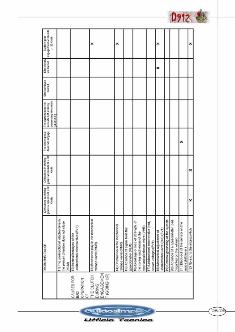
25/28

26/28

27/28
SINTPOMS OF BAD OPERATION