guidelines for mason training corrected -...
TRANSCRIPT
i
Acknowledgement
Earthquake Risk Reduction and Recovery Preparedness Programme for Nepal (ERRRP Project) with the financial support of Government of Japan and UNDP- Nepal is engaged in carrying out various activities related to Earthquake safety and recovery preparedness in five municipalities identified and located in 5 different development region of Nepal. This program helped to strengthen the institutional and community level capacity to plan and implement earthquake risk reduction and disaster recovery preparedness in the country through capacity building, public education and awareness, retrofitting demonstration and preparation of study reports on building safety against seismic risk.
More than 90 % of the houses in Nepal are owner built. The owners' efforts in building production are characterized by a high degree of informality. As the involvement of engineers or professionals in building construction is very limited, after obtaining building permit from the municipality, the owner-builder takes own decisions supported by advise from friends, neighbors and occasionally from professionals. Most of the residential buildings are constructed at the guidance and with the involvement of a head-mason. Thus the necessity to conduct training to the masons to enhance or develop their knowledge on earthquake resistant construction is quite obvious. Though activities relevant to mason training have been undertaken by different agencies since last decade, this book is prepared to address the felt need for having consistent guidelines and training manuals for conducting such mason training programs on earthquake-resistant construction technology.
This Guideline focuses on earthquake safer construction on the most prevailing non-engineered buildings made with stone, brick and block in mud mortar or cement mortar and covers some practical aspects of RCC construction.
I appreciate and acknowledge the efforts of the project officials and professionals' team in preparing this book. I encourage the users of these guidelines for providing creative comments and suggestions to further improve the content and context to make this book more user-friendly.
Purna Kadariya Secretary, Ministry of Physical Panning and Works
ii
Preface
Studies reveal that structural failure of buildings has been the single largest cause of casualties and economic losses resulting from earthquakes. in Nepal number of non engineered buildings significantly outweighs the number of engineered building where their role becomes the most important. Since masons are the key actors in 90% of the buildings production, mason training is the key for promoting safer construction in Nepal. With the realization of such need, many agencies have been involved in conducting training programs on earthquake-resistant construction technologies for masons and local petty contractors during the past 10 years or so. While conducting the training programs, the curricula developed by Department of Urban Development and Building Construction (DUDBC) and National Society of Earthquake Technology - Nepal (NSET) have been in use. However, during such training program it was realized that there should be one harmonized training curricula acceptable to all major stakeholders. In this regard, this is the initiative taken by DUDBC under the Earthquake Risk Reduction and Recovery Preparedness Program for Nepal (ERRRP) program to prepare and standardize the mason training guideline to make it common curriculum throughout the country for all stakeholders. Series of discussion/interaction sessions was organized among concerned stakeholders to invite their comments, inputs and suggestions and this final version incorporates all appropriate inputs.
This guideline is prepared for enhancing the seismic safety of non-engineered buildings in Nepal. Though this book is basically a technical guideline for training local construction workers, I hope social motivators and even common people can make advantage of this book towards earthquake-resistant construction of houses.
Ashok Nath Uprety Director General Department of Urban Development and Building Construction
iii
Foreword
Nepal is a country that stands at 11th rank in the world with respect to vulnerability to earthquake hazards. In this context UNDP/BCPR (Bureau of Crisis Prevention and Recovery) with the support of Government of Japan initiated an Earthquake Risk Reduction and Recovery Preparedness (ERRRP) program in five high risk South Asian countries: Nepal, Bhutan, Bangladesh, India and Pakistan. ERRRP Project is being implemented by the Ministry of Physical Planning and Works (MPPW) in close coordination with other line ministries and Programme Municipalities. ERRRP project is engaged in carrying out various activities related to Earthquake safe constructions, Earthquake preparedness and recovery planning in five municipalities of Nepal located in different development regions. They are Biratnagar, Hetauda, Pokhara, Birendranagar and Dhangadhi.
A study on Risk Perception conducted in 2007 depicts that the number of buildings constructed by only local masons was much greater as compared to the buildings with the involvement of professionals or engineers. Role of Mason is vital in every type of construction even in engineered construction as they are the real implementers. Masons are the ones who recommend house owner on materials selection and construction process. Each mason constructs at least 3/4 houses every year. Masons are thus the key actors in building construction in Nepal but they are not much aware of earthquake technology. Hence earthquake risk reduction can be mainstreamed by training the masons.
In response to the needs of training to the masons, many agencies have been involved in conducting training programs on earthquake-resistant construction technologies for mason including local petty contractors over the last 10 years. Different curricula developed by these agencies are in use which somehow created inconsistency in the quality of the training. The need was urgently felt to have one standard training curriculum.
This guideline is prepared mainly for enhancing the seismic safety of residential houses and does not cover more important and public buildings like schools, health centers etc.
We are thankful to the project officials and professionals' team including NSET in preparing this book.
Sagar Krishna Joshi Suresh Prakash Acharya
National Project Manager, ERRRP National Project Director, ERRRP and
Joint Secretary Ministry of Physical Planning and Works
iv
Table of Content
1 INTRODUCTION ........................................................................................... 1 1.1 Background ................................................................................................. 1
1.2 Goal ............................................................................................................. 1
1.3 Objectives ................................................................................................... 1
1.4 Approach and Methodology ....................................................................... 2
1.5 Scope and Limitation .................................................................................. 4
1.6 Targeted Users ............................................................................................ 5
2 HAZARD AND RISK IN NEPAL .................................................................... 7 2.1 Hazard In General ....................................................................................... 7
2.2 Seismic Hazard and Risk ............................................................................ 7
2.3 Risk Assessment ......................................................................................... 9
3 OVERVIEW OF PAST EARTHQUAKES .................................................... 12
4 PREVAILING BUILDING CONSTRUCTION PRACTICE............................ 14
5 THE NEED FOR MASON TRAINING ......................................................... 18 5.1 Need for Training Guidelines and Training Manual ................................. 18
6 COURSE STRATEGY AND STRUCTURE ................................................. 19 6.1 Understanding and Reaching Mason ........................................................ 19
6.2 Preparing masons for Convincing House Owners .................................... 20
6.3 Providing comprehensive course content and the structure ...................... 21
7 BASIC CONCEPTS OF EARTHQUAKE-RESISTANT CONSTRUCTION . 24 7.1 Basic Factors contributing to seismic safety of buildings ........................ 24
7.2 Earthquake-Resisting Features for Rural Masonry Houses ...................... 24
7.3 Appropriate Construction Materials ......................................................... 25
8 SITE SELECTION ....................................................................................... 26 8.1 Considerations for site selection ............................................................... 26
8.2 Appropriate site for construction .............................................................. 28

v
8.3 Improvement of site .................................................................................. 28
8.4 Improvement in foundation....................................................................... 31
9 APPROPRIATE CONFIGURATION ............................................................ 32 9.1 Plan shape ................................................................................................. 32
9.2 Short walls ................................................................................................ 32
9.3 L-shaped building ..................................................................................... 33
9.4 Box Effect ................................................................................................. 33
9.5 Close building ........................................................................................... 34
10 STONE MASONRY HOUSE ....................................................................... 35 10.1 Different Types of Stone Masonry Houses ............................................... 35
10.2 Main factors for achieving seismic safety in stone masonry houses ........ 35
10.3 Construction of Stone Masonry House ..................................................... 35
11 TIMBER HOUSE ......................................................................................... 52 11.1 Different Types of Wooden wall construction .......................................... 52
11.2 Joints in Wood Frames.............................................................................. 54
11.3 Foundation of Wooden House .................................................................. 54
12 BRICK AND BLOCK MASONRY HOUSE .................................................. 56 12.1 Main factors for achieving seismic safety in Brick/Block masonry houses
................................................................................................................... 56
12.2 Construction of Brick Masonry House in Mud or Cement Mortar ........... 57
12.3 Construction of Block Masonry Buildings ............................................... 70
12.4 Floor/Roof Construction for masonry houses ........................................... 73
13 REINFORCED CONCRETE BUILDINGS ................................................... 78 13.1 Foundation ................................................................................................ 78
13.2 Beam ......................................................................................................... 79
13.3 Column ...................................................................................................... 81
13.4 Beam Column Joint................................................................................... 82
13.5 RC Slab ..................................................................................................... 83
13.6 Quality of concrete .................................................................................... 84

vi
14 REPAIR AND STRENGTHENING OF EXISTING BUILDINGS .................. 86 14.1 Assessment of building damage ................................................................ 86
14.2 Repair and Strengthening .......................................................................... 86
REFERENCES ................................................................................................... 95

1
1 INTRODUCTION
1.1 BACKGROUND
Nepal is located in seismically active area and had experienced several destructive earthquakes in the past causing casualties and economic loss. Earthquake of 1934 was the most devastating one. The seismic records of the country and around the world suggest that a major earthquake on par with the 1934 earthquake occurs approximately every 75 years, indicating that such big earthquake is inevitable in the long run and is likely in the near future.
Studies reveal that collapse of buildings and houses has been the single largest cause of human death and economic losses resulting in from earthquakes. Collapse of the buildings is the result of poor construction practice with many other reasons. Masons are the key actors in 90% of the buildings production in Nepal. Hence mason training program is the key for promoting safer construction in Nepal. With the realization of such need, many agencies have been involved in conducting training programs on earthquake-resistant construction technologies for mason and local petty contractors during the past 10 years or so. While conducting the training programs, the curricula developed by Department of Urban Development and Building Construction (DUDBC) and National Society of Earthquake Technology - Nepal (NSET) have been in use. However, during such training program it was realized that there should be one harmonized training curricula acceptable to all major stakeholders. Hence there is a need to have a common guideline for conducting mason training programs on earthquake-resistant construction technology.
In this regard, this is the initiative taken by DUDBC under the Earthquake Risk Reduction and Recovery Preparedness Program for Nepal (ERRRP) program to prepare and standardize the mason training guideline to make it common curriculum throughout the country for all stakeholders.
1.2 GOAL
The goal is to promote safer construction by providing standard guidelines for mason training in achieving earthquake risk reduction.
1.3 OBJECTIVES
The main objective of this guideline to achieve the above goal; to promote and facilitate earthquake-resistant construction practices in Nepal by providing necessary concept and know-how suitable for local construction workers and communities. The sub-objectives of the guidelines are:
• To provide basic concept as well as construction details for earthquake-resistant construction of the most prevailing building typologies in Nepal.
2
• To promote earthquake-resistant construction using locally available materials.
• To identify and promote local wisdom and indigenous knowledge for earthquake safer construction, if any.
• To provide technical reference to the technicians as well as to the authorities for promoting earthquake safer construction for mason training and awareness programs.
• To provide a basis for mason training and capacity building programs in earthquake-resistant construction.
• To prepare a roadmap for the manuals on earthquake-resistant construction of buildings
• To set the standard course plan for mason training
1.4 APPROACH AND METHODOLOGY
Main Approaches The following approaches have been adopted for preparation of the mason training guidelines:
• Incorporation of experiences of recent earthquakes - Recent earthquake disasters around the world and region have shown that there are several common deficiencies and typical failure patterns in the commonly available building typologies in the developing countries which could be mitigated by some simple improvements in the existing building construction practices. The observations, lessons and experiences of such recent earthquake disasters have been referred.
• Consideration of national building code (NBC) and other similar documents - NBC is regarded as one of the very practical codes in outlining the provisions for earthquake-resistant design and construction of different types of buildings. The provision outlined in different pertinent volumes of NBC has also been the basis. Further, the other best applicable documents and codes such as Indian Seismic Code and codes of Latin American countries have also been considered.
• Inclusion of lessons learnt of the past trainings - Several mason training course including the on-the-job trainings have been conducted in the past by various agencies since 1999. There has been a huge accumulation of lessons and experiences while conducting such mason training programs. The lessons and experiences together with many feedbacks from different training programs have been included.
• Use of pictures and video clips – Pictures and video clips captured by various agencies have been used to the maximum possible level.
3
• Reference of earthquake resistant construction publication – The consolidated experiences in the form of a publication by the World Bank, UN-Habitat, ADPC, NSET, and ERRA also have been referred.
Methodologies The various methodologies carried out in the preparation of this mason training guidelines are as follows.
• Review of the Literature – The existing guidelines and materials of masons training on earthquake-resistant construction technologies were thoroughly reviewed. The review covered the materials published/available within Nepal and outside. The review was carried out with the perspective of evaluating the following:
- Relevance of earthquake-resistant construction technologies in the context of Nepal i.e. suitability and appropriateness for the building typologies available in Nepal
- Suggested techniques of earthquake-resistance to the level of general understanding of common masons
- Compatibility with the commonly used and available tools and equipment
- Training modes, teaching methods and reference materials suggested in the documents to be suitable for common masons
• Analysis - The analysis was focused on three aspects; the overview of the existing building construction practices in various building typologies of Nepal, defects in it and finally consolidation and development of suitable earthquake-resistant techniques. In fact, the review of the several documents was a great source to identify the typical defects in commonly available building typologies and suggested ways of mitigating such defects so as to make them earthquake-resistant.
• Needs Assessment For Training Of Masons - Several mason training courses have been conducted in the past. Now it’s a time to follow-up the effectiveness of those training in the field in imparting earthquake resistant technology to further assess the training needs for masons. The needs analyses in the past were mainly done through informal discussions and interactions. A formal need assessment using structures questionnaire is being conducted for trained and untrained masons with other stakeholders such as instructors of the trainings, practicing engineers and architects who are involved in design and construction supervision etc. to have an in put in the preparation of the guidelines.
• Development Of Draft Guidelines - Based on the above reviews, analysis and needs assessment, draft of the guidelines on earthquake-resistant construction have been developed. The guidelines covers main

4
building typologies and techniques for their earthquake-resistance and strategy for mason training course including key objectives, expected outcomes, outline of course content, duration of the course, methods of training and teaching The draft guideline also presents a broad roadmap for preparation of detailed mason training manual.
• Interaction and Finalization of the Guidelines - The draft guideline was presented to ERRRPP/UNDP. Series of discussion/interaction sessions was organized among concern stakeholders to invite their comments, inputs and suggestions on the draft guidelines. The guideline was finalized incorporating pertinent feedbacks from the discussion/ interaction sessions.
Though the methodology of preparing the Mason Training Guidelines completes here, but this guideline itself forms a basis for the development of Mason Training Manual which is another component of the ERRRP. The methodologies adopted for the Manual includes Development of Draft Mason Training Manual, Interaction of the Manual, Field Testing and Feedback, Finalization of Mason Training Manual and Standardization of Making of Training Guidelines and Manual. These are explained in the Manual itself.
1.5 SCOPE AND LIMITATION
This Guideline focuses on earthquake safer construction on the most prevailing non-engineered buildings made with stone, brick and block in mud mortar or cement mortar and also covers the RCC construction that are prevailing in Nepal. This guideline is mainly for enhancing the seismic safety of residential houses and does not cover more important and public buildings like schools, health centers etc. It is advised to construct schools and other important buildings with higher level of seismic safety using the suitable standards for such structures. The guidelines suggest such strengthening schemes that deliberately minimize the use of more expensive materials in order to keep the cost of earthquake resistance to a minimum. Moreover, the advise and recommendations presented here can be used as good practice for other than residential houses also, although, special attention should be paid to the need of some variation in details that may be required by the importance of such buildings and specifics of the designs.
Further, this guideline is prepared for enhancing the seismic safety of non-engineered buildings located in the seismic prone areas. The concepts and construction details suggested in this guideline are meant for improving the seismic safety of such buildings which lie under the moderate to high seismic areas. In the areas where the seismicity is lower, some of the suggested measures could be omitted as mentioned in each of the corresponding sections. However, it is strongly advised that providing all the measures mentioned in this guideline will enhance seismic performance of buildings significantly.
5
1.6 TARGETED USERS
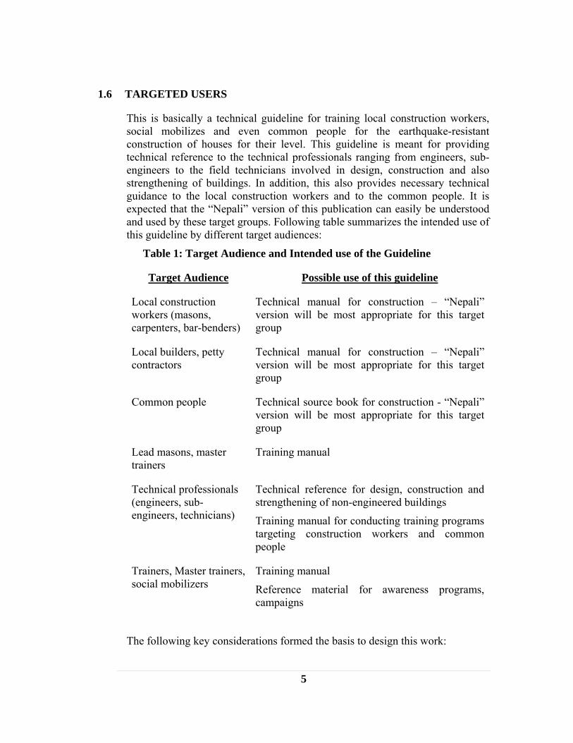
This is basically a technical guideline for training local construction workers, social mobilizes and even common people for the earthquake-resistant construction of houses for their level. This guideline is meant for providing technical reference to the technical professionals ranging from engineers, sub-engineers to the field technicians involved in design, construction and also strengthening of buildings. In addition, this also provides necessary technical guidance to the local construction workers and to the common people. It is expected that the “Nepali” version of this publication can easily be understood and used by these target groups. Following table summarizes the intended use of this guideline by different target audiences:
Table 1: Target Audience and Intended use of the Guideline
Target Audience Possible use of this guideline
Local construction workers (masons, carpenters, bar-benders)
Technical manual for construction – “Nepali” version will be most appropriate for this target group
Local builders, petty contractors
Technical manual for construction – “Nepali” version will be most appropriate for this target group
Common people Technical source book for construction - “Nepali” version will be most appropriate for this target group
Lead masons, master trainers
Training manual
Technical professionals (engineers, sub-engineers, technicians)
Technical reference for design, construction and strengthening of non-engineered buildings
Training manual for conducting training programs targeting construction workers and common people
Trainers, Master trainers, social mobilizers
Training manual
Reference material for awareness programs, campaigns
The following key considerations formed the basis to design this work:

6
• Primary focus is community-initiated building • Focus is to follow simple methods/techniques to build earthquake
resistant houses • Priority is on non-engineered construction practice
7
2 HAZARD AND RISK IN NEPAL
2.1 HAZARD IN GENERAL
Nepal has one of the highest risk profiles in the world, in terms of natural disasters. Complex geology with active tectonic processes, rugged and fragile geophysical structure, very high peaks, high angle of slopes and variable climatic conditions combined with existing poor socio-economic condition, unplanned settlement, rapidly increasing population and low level of awareness make the country including Kathmandu Valley, the capital, prone to almost all types of hazards such as earthquake, floods, landslides, droughts, windstorms, avalanches, debris flow, Glacial Lake Outburst Flood (GLOF), cloudburst, hailstorms, fires, and epidemics. An average of 2 human lives is lost every day due to natural disasters. Although floods and landslides are the most recurrent, earthquakes remain a major concern.
2.2 SEISMIC HAZARD AND RISK
Nepal is very active seismically primarily by its two reasons namely geological and geographical conditions
Geological Condition Nepal is located in a seismically active area. In fact, Nepal Himalayas are a product of the continental collision of the Eurasian and Indian plates, initiated about 40-55 million years ago. The collision resulted in the subduction of the Indian plate underneath Tibet, which continues today at an estimated rate of about 3 cm per year. The subduction produces tectonic stresses along a series of faults parallel to the Himalayan arc. This pressure forces the Himalaya to rise and move horizontally southward along major thrusts. A relative shear strain of about 2 cm per year has been estimated. So the existence of the Himalayan Range with the world's highest peaks is evidence of the continued tectonic activities beneath the country.
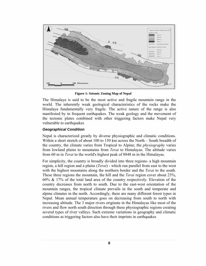
Moreover, the seismic zoning map of Nepal (Figure 2), which depicts the primary (shaking hazard), divides the country into three zones from south to north separated by major thrusts and faults. These zones are elongated in a general east-west direction; the middle part of the country is slightly higher than the northern and the southern parts. A study has identified 92 such faults in Nepal.
8
Figure 1: Seismic Zoning Map of Nepal
The Himalaya is said to be the most active and fragile mountain range in the world. The inherently weak geological characteristics of the rocks make the Himalaya fundamentally very fragile. The active nature of the range is also manifested by in frequent earthquakes. The weak geology and the movement of the tectonic plates combined with other triggering factors make Nepal very vulnerable to earthquakes Geographical Condition
Nepal is characterized greatly by diverse physiographic and climatic conditions. Within a short stretch of about 100 to 150 km across the North – South breadth of the country, the climate varies from Tropical to Alpine; the physiography varies from lowland plains to mountains from Terai to Himalayas. The altitude varies from 60 m in Terai to the world's highest peak of 8848 m in the Himalayas.
For simplicity, the country is broadly divided into three regions- a high mountain region, a hill region and a plains (Terai) - which run parallel from east to the west with the highest mountains along the northern border and the Terai to the south. These three regions the mountain, the hill and the Terai region cover about 23%, 60% & 17% of the total land area of the country respectively. Elevation of the country decreases from north to south. Due to the east-west orientation of the mountain ranges, the tropical climate prevails in the south and temperate and alpine climates in the north. Accordingly, there are many different forest types in Nepal. Mean annual temperature goes on decreasing from south to north with increasing altitude. The 3 major rivers originate in the Himalayas like most of the rivers and flow north south direction through these physiographic regions creating several types of river valleys. Such extreme variations in geography and climatic conditions as triggering factors also have their imprints in earthquakes

9
Other Factors
Besides geological and geographical factors the other socio-economic and cultural factors that put Nepal in the highly seismic risk country include, inadequate preparedness, weak emergency response mechanism, and lack of awareness.
Lack of awareness at all levels; lack of education, lack of integration of disaster concern in development planning and lack of emergency response mechanisms suitable for managing disasters are the principal causes of growing natural hazard risk. Besides, rapid urbanization, poor construction practices and qualities of buildings and lack of preparedness are taken as major causes behind this.
The entire community of the valley including schools and hospitals is at risk to earthquakes. Poor building practices and insufficient emergency and hospital preparedness elevate the risk of mass mortality and injuries from collapsed structures during an earthquake. Moreover, schools buildings are generally constructed without the input of engineers trained in earthquake resistant design or construction. Low budgets increase the likelihood of using poor materials or workmanship. The 1998 Udayapur earthquake in eastern Nepal, illustrated the high vulnerability of these types of structures; approximately 6,000 schools were destroyed, fortunately during non-school hours. This has eventually put particularly, children, the elderly and the infirm at high risk.
2.3 RISK ASSESSMENT
The seismic records of the country suggest that a major earthquake on par with the 1934 earthquake occurs approximately every 75 years, indicating that a devastating earthquake is inevitable in the long run and likely in the near future.
The figure below shows the high level earthquake risk in Nepal
Figure 2: Earthquake Hazard Map of Nepal (modified from World of Natural Hazards, Munich Re
Group, 2000)
There have been number of studies conducted for earthquake risk assessment for Nepal and Kathmandu Valley. Comparative vulnerability studies of countries and

10
cities in earthquake prone areas undertaken by the UN system (Reducing Disaster Risk: A Challenge for Development, UNDP/Bureau for Crisis Prevention and Recovery, 2004) revealed that Nepal is in 11th position in the world in terms of relative vulnerability of the earthquake among 200 countries around the world. Another study conducted in 2000 puts Kathmandu Valley as performing worst among 21 cities around the world in terms of potential risk to earthquake measured in terms of potential death due to earthquake (Global Earthquake Safety Initiative (GESI), UNCRD/Geo-Hazards International, 2001).
Earthquake risk assessment for Kathmandu by the Kathmandu Valley Earthquake Risk Management Project (KVERMP) for a scenario earthquake of IX MMI, level of shaking similar to that due to the 1934 Earthquake, has resulted in the following damage estimates:
• About 60 percent of building stock are likely to be damaged heavily, many beyond repair.
• Almost half of the bridges in the valley could be impassable, and 10 percent of paved roads will have moderate damage; the country’s only international airport may be inaccessible. The prevalence of extremely narrow roads, which could easily be blocked by debris, will exacerbate access problems.
• Approximately 95 percent of water pipes and 50 percent of other water system components (pumping stations, treatment plants, etc.) could be damaged seriously. Almost all telephone exchange buildings and 60 percent of telephone lines are likely to be damaged, requiring significant to moderate repair to be operational. Approximately 40 percent of electric lines and all electric substations are likely to be damaged.
• Estimated casualty figure are approximately 40,000 deaths and about 90,000 injuries requiring hospitalization.
Incorporation of Earthquake Risk Reduction Measures and Risk
A comparative study was carried out by the Kathmandu Metropolitan City (KMC) with technical support from NSET under the UNESCO RADIUS Project to assess the earthquake casualties and damage in two scenarios; one as it is scenario if the existing trend continues and the other by incorporating earthquake risk reduction elements with the implementation of National Building Code. The study finds that the risk has been reduced in the later case as shown in the following table.
Table 2: Earthquake Casualties and Damages in Two Scenarios for Kathmandu Metropolitan City (KMC)
Year Total Buildings
Total damaged
Bldg
Average Bldg Damage
Ratio
Total Population
Day
Total Population
Night
Total Injury
Total Death
Damage estimation in existing situation (No DRR situation, Building Code not implemented) 2001 79,475 40,869 51.4 989,291 671,846 130,516 14,042 2006 98,234 49,575 50.5 1,147,732 777,795 147,446 15,752
11
2011 116,063 58,095 50.1 1,362,609 915,071 174,188 18,348 2021 144,406 71,493 49.5 1,989,075 1,319,597 251,673 26,209
Damage estimation in improved situation (with DRR, Building Code implemented)) 2006 98,234 44,117 44.9 929,063 777,795 103,477 10,917 2011 116,063 48,217 41.5 1,007,118 915,071 103,153 10,656 2021 144,406 54,596 37.8 1,344,148 1,319,597 126,155 12,671
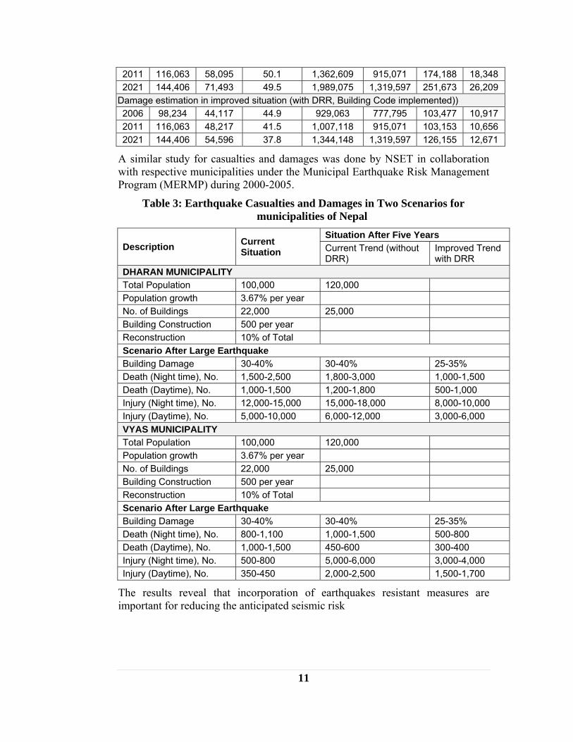
A similar study for casualties and damages was done by NSET in collaboration with respective municipalities under the Municipal Earthquake Risk Management Program (MERMP) during 2000-2005.
Table 3: Earthquake Casualties and Damages in Two Scenarios for municipalities of Nepal
Description Current Situation
Situation After Five Years Current Trend (without DRR)
Improved Trend with DRR
DHARAN MUNICIPALITY Total Population 100,000 120,000 Population growth 3.67% per year No. of Buildings 22,000 25,000 Building Construction 500 per year Reconstruction 10% of Total Scenario After Large Earthquake Building Damage 30-40% 30-40% 25-35% Death (Night time), No. 1,500-2,500 1,800-3,000 1,000-1,500 Death (Daytime), No. 1,000-1,500 1,200-1,800 500-1,000 Injury (Night time), No. 12,000-15,000 15,000-18,000 8,000-10,000 Injury (Daytime), No. 5,000-10,000 6,000-12,000 3,000-6,000 VYAS MUNICIPALITY Total Population 100,000 120,000 Population growth 3.67% per year No. of Buildings 22,000 25,000 Building Construction 500 per year Reconstruction 10% of Total Scenario After Large Earthquake Building Damage 30-40% 30-40% 25-35% Death (Night time), No. 800-1,100 1,000-1,500 500-800 Death (Daytime), No. 1,000-1,500 450-600 300-400 Injury (Night time), No. 500-800 5,000-6,000 3,000-4,000 Injury (Daytime), No. 350-450 2,000-2,500 1,500-1,700
The results reveal that incorporation of earthquakes resistant measures are important for reducing the anticipated seismic risk

12
3 OVERVIEW OF PAST EARTHQUAKES History of Earthquakes
Nepal has a long history of destructive earthquakes which extends back to 1255 AD. After that, there are records of several devastating earthquakes. Major are in 1408, 1681, 1810, 1833, 1866, 1934, 1980 and 1988 AD. According to the seismological center of Nepal medium and small size earthquakes occur frequently in different part of the country.
Three earthquakes produced intensities of IX-X in Kathmandu Valley in the 19th Century, in 1810, 1833 and 1866. There have been a number of devastating earthquakes within living memory such as those in 1934, 1960 and 1988. Among the earthquakes recorded in the past, earthquake of 1934 A.D. also known as Great Bihar Earthquake was most destructing. Casualties and Damage
The damage and casualties due to the earthquake events have been great. In the past century alone, over 11,000 people have lost their lives in four major earthquakes. The 1934 earthquake produced an intensity of IX-X on the Modified Mercalli Intensity (MMI) scale in Kathmandu Valley, and destroyed 20% and damaged 40% of the valley’s building stock. In Kathmandu itself, 12,397 houses collapsed, 43,342 houses partially damaged and the death toll were 4,296 (Rana, 1935). Many of the temples in Bhaktapur were destroyed as well. This earthquake is not an isolated event. There are frequent small to medium-sized earthquakes in different parts of the country with localized effects. Nepal continues to face a high level of earthquake hazard and risk.
Table 4: Casualties and Damage made by past earthquakes in the Kathmandu Valley
Year Date EarthquakeEpicenter
Casualties Buildings / Temples Death Injuries Collapsed Damage
1988 21 Aug. Udayapur 8 71 650 1814 1934 15 Jan. Bihar/Nepal 4,296 - 12,397 43,342 1837 17 Jan. - - - - - 1833 26 Aug. - 43 30 18,000 - 1823 - - - - - -
1810 May - Moderate casualties Many buildings and temples collapsed
1767 June - - - - -
1681 - - - - Many buildings and temples collapsed
1408 - - Heavy casualties Many buildings and temples collapsed
1260 - - Heavy,
Widespread famine and epidemic
- -
1255 7 June - 1/3 of total population including King Abhaya
Malla Killed
Many buildings and temples collapsed
13
Source: JICA, 2002, NSET, 2002 and Rana, 1935
Economic Loss
In terms of economic loss, the total direct loss alone due to disasters in the last 37 years is estimated to be more than US$ 177 million. It should be noted that the country’s total annual budget is around US$ 1.8 billion. Causes of Casualties and Loss
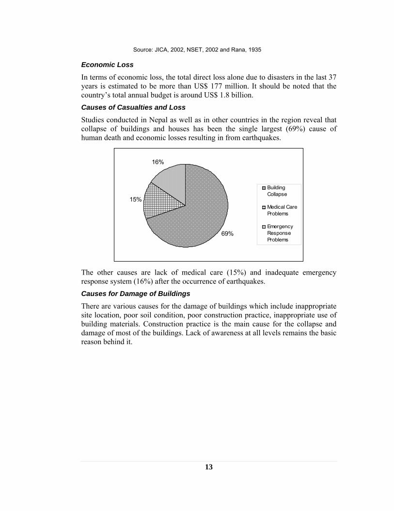
Studies conducted in Nepal as well as in other countries in the region reveal that collapse of buildings and houses has been the single largest (69%) cause of human death and economic losses resulting in from earthquakes.
69%
15%
16%
BuildingCollapse
Medical CareProblems
EmergencyResponseProblems
The other causes are lack of medical care (15%) and inadequate emergency response system (16%) after the occurrence of earthquakes. Causes for Damage of Buildings
There are various causes for the damage of buildings which include inappropriate site location, poor soil condition, poor construction practice, inappropriate use of building materials. Construction practice is the main cause for the collapse and damage of most of the buildings. Lack of awareness at all levels remains the basic reason behind it.

14
4 PREVAILING BUILDING CONSTRUCTION PRACTICE
Building Producers
The government has adopted a role of a facilitator /enabler rather than a provider in housing sector as stated in the National Shelter Policy 1996. Firstly it does not have enough land of its own to provide social housing schemes as the land is privately owned and very expensive. Furthermore, housing does not fall in the priority sector as health and education. So the government does not produce buildings for social housing schemes.
Recently private sector has emerged professionally and commercially in producing buildings for housing in urban areas. However, they are far behind in meeting the demand. Hence housing is still solely the responsibility of an individual.
Construction of a house falls in the domain of owner builder as housing as a whole is the responsibility of an individual. More than 90 % of the houses are built by this process and popularly known as Owner-Build. This process normally takes years and even decades. The owner builders' efforts in building production are characterized by a high degree of informality. After registering the plot, getting design and drawings done and obtaining building permit from the municipality, the owner builder makes own decisions supported by advise from friends, neighbors and occasionally from professionals. S/he deals with the building material suppliers and small contractors on personal basis. S/he manages to do as much as to keep the cost down by organizing most activities himself.
As the involvement of engineers or professionals in building construction is very limited for various reasons, most of the residential buildings are constructed at the guidance and with the involvement of a head-mason or a contractor who generally do not have any modern knowledge on earthquake resistant construction. Such type of buildings prevails throughout the country including the urban areas. Key Actors in Construction Practice
Primarily two types of actors are found to be involved in the construction process from technological perspective. They are the engineers or professionals and the masons. The levels of involvement of these key actors in the various stages of construction process that are practiced in Nepal are of three types.
Engineered Constructions
There are many buildings designed, supervised and constructed as per standard engineered practices. In such buildings the involvement of engineers or professionals remains throughout the whole process right from the design, construction and completion. The masons simply follow the instructions given to them.
Semi-Engineered Constructions

15
In this type of buildings involvement of the engineers or the professions is limited to design stage only and occasionally at some critical points such as foundation laying, plinth level and slab casting. Masons with the contractors take the rest of the responsibility. Non-engineered Constructions
A large percentage of the building stock even in Kathmandu Valley is non-engineered where there is no involvement of any professional at any stage. Only Masons are the all in all. It is estimated that in Kathmandu approximately more than 5000 of such buildings are added every year. Most of them lie outside the jurisdiction of municipal boundary.
A study on Risk Perception done in 2007 also depicts this fact as shown in the following figure. About 800 households in 2 communities of Kathmandu Valley were surveyed. The number of the buildings constructed by only local masons was much greater as compared to the buildings with the involvement of professionals or engineers.
Figure 3: Who constructed your house?
Process of Technology Transfer
The knowledge and technology required by the engineers and professionals for the construction is acquired through the formal training in the academic institutions while by the masons, it is basically learning by doing. The transfer of knowledge and technology takes place in a very informal way. Generally, a labor working in association with masons for a long period of time turns into a mason, then head mason. Sometimes a younger generation seeing the elder generation working as carpenter or mason gets inspired to follow the same occupation. This is still the case in various parts of the country. However, particularly in
16
Kathmandu, the traditional system of “occupational castes” for example, “Sikarmi” (carpenter), “Dakarmi” (mason), “Lohakarmi” (blacksmith) etc was the basis for continuation of the traditional skills and wisdom and their continued application and integration into the building construction process, by passing the knowledge from generation to generation. The construction technologies have transferred from one generation to another generation through a specific group of people who were specialized in the field of building houses. In this process several traditional wisdom and technology that were earthquake resistant were wrongly used or misinterpreted and some were lost. Role of Mason in Building Construction
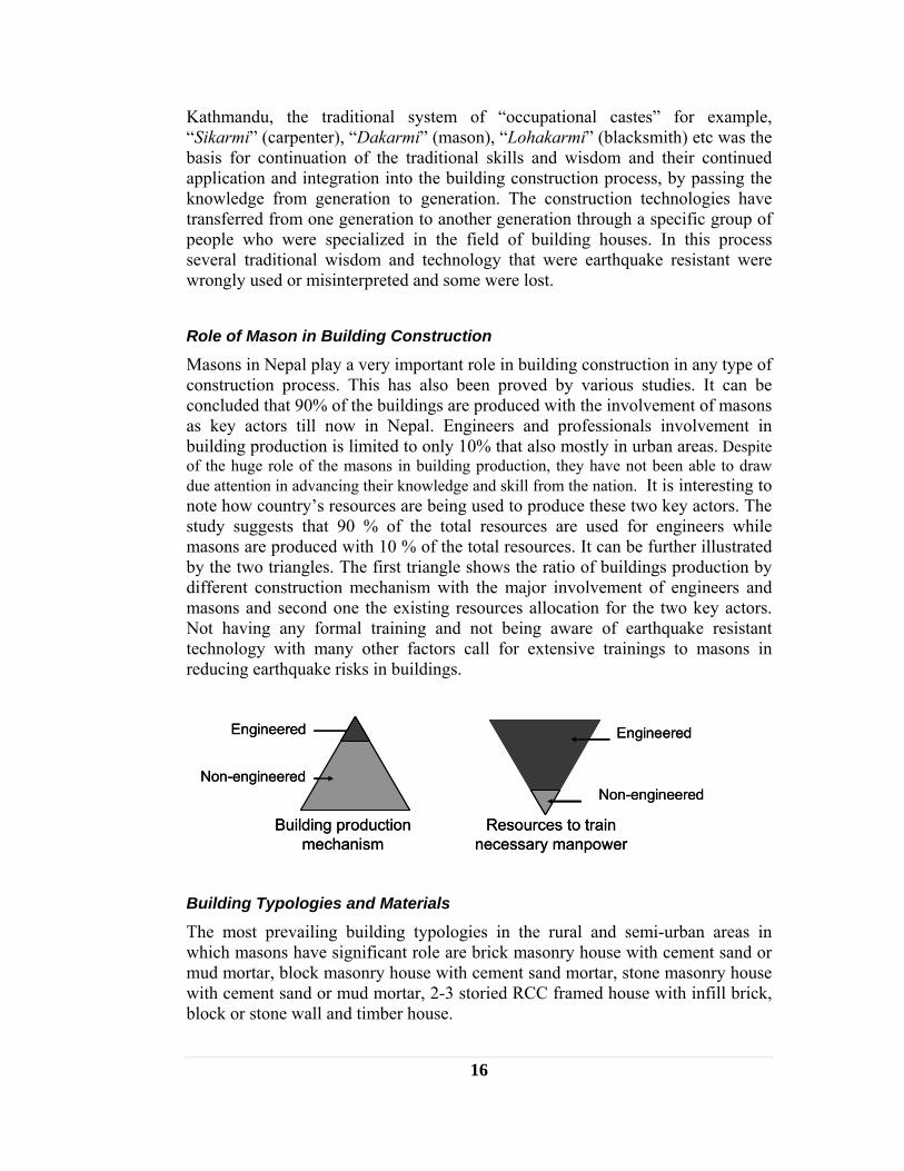
Masons in Nepal play a very important role in building construction in any type of construction process. This has also been proved by various studies. It can be concluded that 90% of the buildings are produced with the involvement of masons as key actors till now in Nepal. Engineers and professionals involvement in building production is limited to only 10% that also mostly in urban areas. Despite of the huge role of the masons in building production, they have not been able to draw due attention in advancing their knowledge and skill from the nation. It is interesting to note how country’s resources are being used to produce these two key actors. The study suggests that 90 % of the total resources are used for engineers while masons are produced with 10 % of the total resources. It can be further illustrated by the two triangles. The first triangle shows the ratio of buildings production by different construction mechanism with the major involvement of engineers and masons and second one the existing resources allocation for the two key actors. Not having any formal training and not being aware of earthquake resistant technology with many other factors call for extensive trainings to masons in reducing earthquake risks in buildings.
Building production mechanism
Engineered
Non-engineered
Resources to train necessary manpower
Non-engineered
Engineered
Building production mechanism
Engineered
Non-engineered
Resources to train necessary manpower
Non-engineered
Engineered
Building Typologies and Materials
The most prevailing building typologies in the rural and semi-urban areas in which masons have significant role are brick masonry house with cement sand or mud mortar, block masonry house with cement sand mortar, stone masonry house with cement sand or mud mortar, 2-3 storied RCC framed house with infill brick, block or stone wall and timber house.

17
The most common building materials that the masons are dealing with for wall are bricks, stones and tree branches and for roofing C. G. I. Sheet, R.C.C., tiles/slates and straw/thatch. 48 % of the housing units are walled by mud-bonded bricks/stones. Other materials include wood and tree branches (19 %), cement bonded bricks/stones and concrete (18 %) and others (16 %). Various types of building blocks for wall such as stone-crete block, hollow block have emerged as an alternative to walling material. Timber building though not in much practice due to the unavailability of timber for environmental reason combined with high cost, but still find in some areas. Existing Legislations in Construction
The two construction control systems namely Building By-Laws and National Building Code are being practiced in Nepal in urban centers.
Collapse of buildings and houses has been the single largest cause of human death and economic losses resulting in from earthquakes in Nepal also. Effective enforcement of earthquake resistant building codes and control system can reduce the loss significantly. Realizing this fact, the National Building Code (NBC) has been developed in 1992 to improve the structural safety of buildings, to reduce impact of earthquakes in life and livelihood of the people.
It is almost 12 years since the code is developed but implementation has not been as effective. Only 2 municipalities Kathmandu and Lalitpur out of 58 have implemented it and 2 more municipalities (Dharan and Byas ) have just started. Implementation of NBC is not only a technical issue. It also includes social, legal and institutional aspect such as lack of awareness, lack of institutional mechanism for implementation and inadequate capacity of implementing authorities. Despite of many constraints and challenges implementation of NBC is a key factor in reducing the disaster risk and hence is very important. Therefore there is a need to go ahead about implementing NBC with various pragmatic and innovative ideas.

18
5 THE NEED FOR MASON TRAINING Masons are the key actors in building construction in Nepal. However, they are not aware of earthquake technology and other knowledge that can reduce the earthquake risk. Hence earthquake risk reduction can be mainstreamed by giving the training to the masons. There are ample of reasons for the need of training for the masons. Role of Mason is vital in every type of construction even in engineered construction as they are the real implementer. If they do not understand, they can not perform accordingly and the quality does not improve. The engineers and professionals only work on papers and can tell verbally. Furthermore, the number of non engineered buildings outweighs the engineered building where their role becomes the most important. Masons are the ones who recommend house owner on materials selection and construction process, House owners also listen more to mason than engineers. Mason have greater role in building production in terms of quantity as well. Each mason constructs at least 3/4 houses every year. So giving a training to mason has a multiplier effect. In addition, engineered buildings are mostly in urban area, so in order to reach to greater area throughout the country, masons need to be trained. Realizing this fact some such trainings have been initiated in the recent past. A total number of 800 masons have been trained in Kathmandu valley in earthquake resistant building construction till July 2008 which is still nominal as compared to the 9000 buildings constructed per year in municipal areas of Kathmandu valley.
5.1 NEED FOR TRAINING GUIDELINES AND TRAINING MANUAL
In response to the needs of training for the masons, many agencies have been involved in conducting training programs on earthquake-resistant construction technologies for mason including local petty contractors over the last 5 years. Different curricula developed by these agencies are in use which somehow created inconsistency in the quality of the training. The need was urgently felt to have one standard training curriculum acceptable to all major stakeholders. Hence there is a need for having common guidelines and training manuals for conducting mason training programs on earthquake-resistant construction technology.

19
6 COURSE STRATEGY AND STRUCTURE Seismic risk in buildings can be reduced by making buildings earthquake resistant. Earthquake resistant buildings can be made only by enhancing the knowledge and skill of the people involved in the construction process. There are two distinct groups of people in it and they are the construction workforce and house owners. The workforce in the construction includes masons, carpenter and bar-benders. Effective transfer of knowledge and skill depends on the course strategy and course structure. What to be included and how that is delivered to the targeted audience are the important aspects of the training. The following three course strategies have been adopted for this mason training to reach the masons as well as the house owners in reducing the seismic risk of the buildings.
6.1 UNDERSTANDING AND REACHING MASON
This is a training for mason and it is important to understand the mason first to achieve the very objective of the training effectively. Understanding mason means knowing their educational level, working experiences, local construction terminologies, capacity to understand drawings, their relationship with engineers and house owners, the language they speak, their assertiveness and many other socio-cultural aspects. Information on these factors helps the trainer to understand the areas to be focused so that necessary adjustment can be made easily in delivery as well as field exercise without deviating from the main objective of the training.
Most of the times, the training group is diverse in nature in terms of age, working experience, language, educational level and geographic area. Majority of the masons are literate in Nepal and hence can read and write. However, there are few who are illiterate. There are some who have even attained the college education. But a best way is to focus more on pictures and practical knowledge with lots of examples rather than theory.
Though Nepali language is spoken and understood by all, local accent makes it slightly different in different areas. When it comes to local construction terminologies, it is always better to use those words. Moreover, there is also considerable workforce from India in construction. In such situation special attention is to be given to this group.
As the targeted audience is the workforce from construction sector, the group may become quite heterogeneous. The group may have bar-benders, mason and petty contractors having various types of work experience. Some of them may be good at reinforcement works and some in wall construction details. Some can understand and make drawings and some may not. Special care is to be given on how drawing is to be read while dealing with plan or section of the construction details. Furthermore, trainer needs to explain the calculation aspect in a simple way.
It is also quite natural to have trainees of different age groups. Young have little experience and older have more. Young were found more eager to learn new
20
concepts while it is more difficult for older to make them de-learn what they have learnt already. But at the same time, older masons may know many indigenous earthquake technologies which they have been practicing knowingly or unknowingly for years. These technologies need to be explored in the training.
With few exceptions, most of the masons are hesitant to speak of what they know. This may be the first type of training that masons are participating. Sometimes, presence of petty contractors makes them think that they know less than the contractors and remain silent. It becomes necessary for the trainer to encourage them all to interact and ensure all participate equally.
The trainer needs to understand all these factors to reach the mason in promoting safer construction practice.
6.2 PREPARING MASONS FOR CONVINCING HOUSE OWNERS
Masons in Nepal play very important role in building construction as 90% of the buildings are produced at the guidance and with the involvement of a head-mason or a petty-contractor as key actors till now. Masons are the ones who recommend house owner on materials selection and construction process. Each mason constructs at least 3/4 houses every year. There is a strong linkage between the masons and house owner.
Since masons are the key actors in building construction, they can also be the key actors in convincing the house owner in promoting safer construction practice and eventually reducing the seismic risk. Hence preparing mason for convincing the house owners has also been adopted as one of the strategies.
Various research studies reveal that earthquake risk of the building can be reduced greatly by incorporating certain elements and correcting some techniques in the conventional construction practices. The general perception of the people is that making building earthquake resistant is very costly. This is a great challenge for professionals to convince the people in adopting safer construction practice. It is even more difficult for mason to make people understand the importance of earthquake resistant buildings. Incorporating earthquake resistant elements in the building requires some additional cost and people are obviously very much concerned about this. It definitely adds cost to the building, however, not as much as it is perceived. This perception needs to be clarified. The mason needs to be well prepared in this aspect.
Changing the perception of the people on the seismic risk of the buildings is not an easy task. However, it is possible. It takes some time to break the ice and needs a lot of passion and it will pay in a long run. The following few points help to clarify the misconception regarding the cost and make understand the importance of incorporation of earthquake resistant elements in the building. It will be easier for mason to convince the house owner by telling these points.
21
• Making buildings earthquake resistant costs only 5-10% of the building cost for civil works. Structural cost alone, which means the cost of walls, columns, slabs and beams, is estimated to exceed by only 25% as compared to the same without incorporation of earthquake resistant features. Though the cost of finishing varies widely depending upon the level of finishing, the structural cost generally comes to be less than 50 % of the total cost of civil works. So, if a building is completed for Rupees 50 lakhs without seismic considerations, inclusion of it will cost extra 5 % i.e. Rs.2.5 lakhs only.
• If a building is damaged in an earthquake, the cost of reconstruction is
much higher than the additional cost that is needed for new construction for making it earthquake resistant.
• Even in a situation when only building is damaged, economic loss and
functional disability of services is quite significant to affect the life of the people adversely. For example, people may face very hard time for several months if the water tank is destroyed during earthquake.
• Safety of the people living in the building can not be compared with any
cost. If a person is killed due to collapsed of building, the pain lasts for life of other family members. Most of the human casualties in the past earthquakes had been caused due to collapse of the building. No one would like to build such buildings and go through such pain.
• In many instances it is not the matter of money. We spend lot of money in
the finishing which can be done later. We can put fixtures later, have marble floor in the nest phase. But incorporation of vertical reinforcement at corners and junctions and putting sill band at the window level can not be done after completion of the building.
In addition, preparing a small booklet with photographs of collapsed and damaged buildings caused by earthquakes in neighboring countries or in the region and showing to the house owners can be very effective in convincing them. They also need to be complemented by pictures with solutions to be more effective. In most of the time such photographs speak themselves.
6.3 PROVIDING COMPREHENSIVE COURSE CONTENT AND THE STRUCTURE
Another strategy of the course is to provide a comprehensive content for mason training. It is important to understand all the aspects of safer construction practice to have a complete picture as they are often interlinked with each other. Comprehensive course gives a broader perspective.

22
Though this is a basic course for masons who are engaged in construction practice, this course is not limited to construction details alone, but also provides other information to complement the construction practice. The course covers basic concept of earthquake, cause and effect, overview of seismic risk in Nepal, site selection and configuration of buildings and building construction control mechanism. In addition to the earthquake resistant construction details for the new construction, it also covers the technologies for strengthening of the existing buildings. This is a complete package on earthquake resistant building construction technology. The structure of the course is based on this strategy.
Course Content The following are the topics provided by the course covering most prevailing building typologies and other general information.
• Brick masonry house with cement sand or mud mortar • Block masonry houses with cement sand mortar • Stone masonry houses with cement sand or mud mortar • 2-3 storied RCC framed houses with infill wall of brick, block or stone • Timber houses • Cause and effects of earthquakes and seismicity of Nepal • Consideration for good site selection and appropriate configuration of
houses • Repair and strengthening of existing houses • Introduction to National Building Code of Nepal (NBC) •
Course Structure Covering the comprehensive content, the course has been structured into 4 modules based on the themes of the topics and each module has been sub-divided into sessions. Following are the modules and sessions:
A. Module 1: Basic Concepts
• Earthquake Basics and Effects of Earthquake • Consideration for Site Selection • Appropriate shape and size of buildings
B. Module 2: Earthquake-Resistant Construction
• Earthquake-Resistant Construction of Masonry House • Earthquake-Resistant Construction of RCC building • Earthquake-Resistant Construction of Timber House • Quality of Materials and Construction Process
C. Module 3: Strengthening of Existing House

23
• Repair and Strengthening of existing buildings – general idea
D. Module 4: Considerations for Promoting Safer Construction Practice
• Role of Masons in promoting safer construction practice (tips for awareness of people)
• Introduction to National Building Code of Nepal (NBC)

24
7 BASIC CONCEPTS OF EARTHQUAKE-RESISTANT CONSTRUCTION
7.1 BASIC FACTORS CONTRIBUTING TO SEISMIC SAFETY OF BUILDINGS
7.2 EARTHQUAKE-RESISTING FEATURES FOR RURAL MASONRY HOUSES
Following are the main elements to be incorporated in a house to make it stronger and more resistant to earthquakes:
1. Horizontal Bands at different levels
2. Corner strengthening with stitches
3. Vertical Reinforcement
4. Tying floor/roof rigidly with lateral load resisting elements (walls / columns)
5. Diagonal Bracing
►Proper site selection: The proper site selection is very important for stable and disaster safe construction.
►Appropriate planning: The shape, size and proportion of a building are important for its seismic safety.
►Good foundation resting on a Firm Base: The quality of foundation and the base on which the foundation rests are equally important for the safety of a building.
►The building has to act as a single unit for a good earthquake resistance: This can be achieved by incorporating following elements in the construction of a building:
− Vertical reinforcement: − Horizontal bands well connected to the vertical reinforcements and embedded in
masonry − Diagonal bracing (horizontal and vertical) − Lateral restraints
►Better bonding within masonry: The type and quality of bond within the walling units is the main contributor to the integrity and strength of the walls.
►Controlled size and location of openings: Large un-stiffened openings create soft story effect leading to a deformation of building during an earthquake. To prevent such effects the opening size and location has to be controlled.
►Light construction: The lighter structures absorbs less earthquake force and hence less effect. Lighter materials like timber, bamboo, straw is preferred provided they are available.

25
7.3 APPROPRIATE CONSTRUCTION MATERIALS
The following should be used as general guidelines for selecting appropriate construction materials for different building construction types. More detailed guidelines for selecting appropriate materials are given in the corresponding sections for different building construction types.
Brick: Over-burnt, under-burnt and deformed bricks should be avoided.
Boulder stone: Round boulders, unlike angular ones, do not provide uniform binding when used in wall construction, resulting in movement of individual boulders and ultimate failure of the wall during earthquake shaking. Therefore, round boulders should be avoided, or broken into angular pieces before being laid.
Quarry stones: Easily breakable soft stones should be avoided. Only solid and strong quarry stones with no obvious fractures should be used.
Mud Mortar: Mud for mortar should be free from organic materials. It should also be free from pebbles and other hard materials which will upset the mortar thickness. Dry mud should be thoroughly kneaded with water to prepare a dense paste. Property of mud is discussed in the following sections.
Wood: Wood is used in door/window, for corner strengthening, and also for the roof. Treated wood should be preferred to the untreated ones.

26
8 SITE SELECTION Site for building construction should be selected carefully. Site should be stable and safe enough to withstand the building load. Hazardous areas should be avoided for building construction to minimize risks against natural disasters. Site Investigations help in identifying existence of any potential hazard such as sliding, erosion, land subsidence or liquefaction. However, detail investigation of each site in rural and sub-urban areas is not feasible and affordable. Therefore, general site investigation is recommended and the local practice for addressing any local hazard should also be identified, judged and applied. Following points are considered to be helpful for selecting appropriate site for buildings construction.
8.1 CONSIDERATIONS FOR SITE SELECTION
8.1.1 Steep and unstable slopes Building should not be constructed near or on steep and unstable slopes. Steep slopes made of soft or crumbly rock, clayey loam or deposits materials are not stable and may easily fall down during earthquake shaking or even in normal time or during rainfalls. Also, higher damages to buildings have been observed near or on steep slopes during earthquakes due to shaking amplification. Therefore, such steep slopes should be avoided.
Figure 4: Potential hazard at steep slopes (Source: Anti-seismic construction handbook,
CRATerre)
8.1.2 Areas susceptible to landslides and rock fall Landslides or rock fall areas should be avoided while selecting a site for building construction. In normal times, the slopes may look stable, but slope failure could be triggered by an earthquake. Landslides can completely wash out the building. Rock fall (Figure 5) can damage buildings partially or completely. However, building in these areas can be constructed after providing proper precaution by retaining walls and green barriers. Simple indication of sustained stability of a slope is the existence of upright standing trees on it. Abnormally inclined trees on a slope indicate instability of the hill slope.

27
Figure 5: A rock fall area
8.1.3 Filled area: Building should not be constructed on un-compacted filled ground. In a filled ground, the bearing capacity of foundation sub-soil would be very low and settlement of foundation may occur. Also, foundation may be exposed in due course of time due to easy scouring of the filled up soil. If a building has to be constructed on a filled ground, its foundation should be deep enough so as to rest on firm ground surface below the fill.
8.1.4 River banks: River banks are susceptible to frequent flooding (Figure 6), scouring and also susceptible to liquefaction during earthquakes. Buildings should be far enough from the flooding zone of river. Construction in such areas should be undertaken only after carrying out necessary river protection works.
Figure 6: Flood Hazard due to proximity to River

28
8.1.5 Water logged area: In water logged areas, building may face a variety of problems such as flooding, foundation settlement and liquefaction. Construction of buildings on loose sand and soft clay should be avoided. In case the building is to be constructed in a water logged area, sufficient drainage should be provided by constructing drainage-ditches; or the ground level of the building should be raised by making a plinth of compacted earth, or the house should be built on stilt.
8.1.6 Geological fault and Ruptured areas Buildings should not be constructed within 500 m of the surface trace of an active fault or any ruptured areas in order to avoid fault-rupture hazard. The area on either side of the fault trace could be developed as recreational park, farm, orchard etc
8.1.7 Trees Buildings should not be constructed close to any big tree. Roots of the tree may penetrate into the foundation and damage the whole building. Also, if a building is near to a big tree, there is a possibility of falling of the tree in strong winds and storms on the building.
8.2 APPROPRIATE SITE FOR CONSTRUCTION
Considering above mentioned hazardous sites, a proper site for building construction will be of following features:
• Compact soil and stable ground • Nearly flat terrain or ground with low slopes • Far from river • Far from big trees • Far from geological fault and ruptured area • Far from unstable and steep slope • Far from landslide and rock fall
8.3 IMPROVEMENT OF SITE
Whenever it becomes necessary to construct building on a weak or inappropriate ground, it is advised to construct after the improvement of site. But in general, improving site is an expensive option and may not be feasible for residential
Figure 7: Geological fault (Source: CRA TERRE - Anti-seismic construction handbook)

29
building construction. Following are some methods to improve site for building construction:
8.3.1 Construction in damp or water-logged site Since saturation of foundation soil is dangerous from liquefaction and landslide, the site should be kept well drained. A waterproof apron may be provided all round the building to prevent seepage of water under the foundations. Water drains should be constructed away from the buildings at the edges of the apron. In the area where it is impossible to avoid selection of a site with saturated soil, pile foundations going to depths of 8 to 10 m will generally be adequate.
8.3.2 Construction in sloping ground Building should not be constructed on a steep slope ground. Building should be far enough from the toe of the slope as shown in the figure.
However, whenever it becomes unavoidable to construct a building on a steep sloping ground, stepped strip footing can be made for foundation as shown in the figure. The minimum depth of a foundation should be measured from the existing ground level on the filled part and from the finished ground level on the cut part, and this should not be less than 750 mm (2.5 ft). Each step should not be narrower than two times the wall thickness at the base of the superstructure, as shown in figure 9.
Figure 8: Preparing a site in sloping area

30
Distance of two walls
T
X = Minimum 2T or 3 ft whichever is more
H = Not more than 1 ft.
V = Not more than 3 ft. without provision of retaining wall
T = Thickness of wall
Floor finish + 1 ft.
Finished Ground Level +00
4 ft. (min.)
4 ft. (min.)
4 ft. (min.)
4 ft.
(min
.)
ORIGINAL GROUND LEVEL
Distance of two walls
T
X = Minimum 2T or 3 ft whichever is more
H = Not more than 1 ft.
V = Not more than 3 ft. without provision of retaining wall
T = Thickness of wall
Floor finish + 1 ft.
Finished Ground Level +00
4 ft. (min.)
4 ft. (min.)
4 ft. (min.)
4 ft.
(min
.)
ORIGINAL GROUND LEVEL
Figure 9: Foundations at different levels in sloping area
8.3.3 Protection of Slopes A. Retaining Wall
Providing retaining walls is a most commonly used solution for maintaining steeper slopes in position, providing them stability, and for preventing those from falling down Retaining walls are widely used in hilly areas. Commonly used material for constructing retaining walls is stone either in dry masonry or in cement mortar; RCC retaining walls being more modern and advanced form of retaining structure.
Retaining walls can be used to solve problems where there is limited right of way and confine ground slopes within practical limits and to stabilize steep cut and embankment slopes.
Figure 10: Safe distance from retaining wall
It is necessary to have a security space between the downstream retaining wall and the house and the retaining wall should not be used as the structural wall for a house. An ideal distance between retaining wall and the house wall should be equal to the height of the retaining wall.

31
B. Gabion Wall
Gabion walls are another common technology used for protection of steep slopes and also protection of river backs and embankments. A gabion is a heavy duty, galvanized steel welded wire or twisted wire mesh basket, in the shape of a box, which is divided by wire diaphragms into cells and filled with heavy material (typically rocks, or broken concrete) that cannot escape through the mesh openings. It generally is used as a construction block, becoming part of a larger unit of several gabions tied together to form a structure. Main features of the gabion as a construction material are:
• Good Strength • Permeability • Flexibility • Easy Installation • Durability • Low Cost • Aesthetics • Low Environmental Impact
These features are especially advantageous in constructing a range of retaining walls for general earth retention, bridge abutments (for short or light duty bridges), as well as wing walls and end protection for culvert structures.
8.4 IMPROVEMENT IN FOUNDATION
As stated, improvement of site is an expensive option. However, in place, improvement in foundation structure may be an optimal solution for common residential houses. Tying up whole foundation structure with a foundation band or a beam is one of the appropriate solutions. Normally, in foundation of residential buildings, no bands or beams with reinforcing bars are provided; and whenever there is ground shaking building may start disintegrating from the foundation or building may fall down when there is slight movement of the ground. But if foundation band is provided, this band will help the building to act as a one unit and prevent disintegrating. A typical layout of foundation band for isolated footing of frame structure is shown in the figure. A band similar to plinth or lintel band as will be discussed on the following chapters can be provided in strap footing of masonry structures.
Figure 11: Typical system of Gabion walls
Figure 12: Typical layout of foundation beam for frame structure (view inside ground)
32
9 APPROPRIATE CONFIGURATION The behavior of a building during earthquakes depends not only on the strength and quality of different structural members but the behavior depends critically on its overall shape, size and geometry. Constructions with asymmetrical plan and elevation are more vulnerable to earthquake than those having symmetrical plans and elevation because of the fact that non-uniformity in building shape and geometry will lead to the unequal distribution of seismic forces in different parts and structural members of the building leading to the excessive forces in some critical locations only which will cause damage to that part only and finally collapse starting from that location. Hence, at the planning stage itself, good shape, and appropriate size and geometry should be chosen for ensured seismic safety of buildings. Following sections will describe appropriate configuration for buildings.
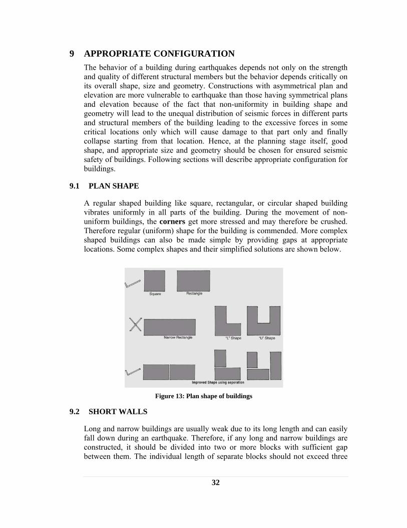
9.1 PLAN SHAPE
A regular shaped building like square, rectangular, or circular shaped building vibrates uniformly in all parts of the building. During the movement of non-uniform buildings, the corners get more stressed and may therefore be crushed. Therefore regular (uniform) shape for the building is commended. More complex shaped buildings can also be made simple by providing gaps at appropriate locations. Some complex shapes and their simplified solutions are shown below.
9.2 SHORT WALLS
Long and narrow buildings are usually weak due to its long length and can easily fall down during an earthquake. Therefore, if any long and narrow buildings are constructed, it should be divided into two or more blocks with sufficient gap between them. The individual length of separate blocks should not exceed three
Figure 13: Plan shape of buildings

33
times its width. The foundation of these blocks may be connected to each other and separation can be made only in the superstructure.
9.3 L-SHAPED BUILDING
‘L’ shaped buildings are irregular and inappropriate. However, small projection can be allowed, if the projection is less than one-sixth of the width of the building.
9.4 BOX EFFECT
One of the essential principal of earthquake-resistant construction is to use a compact, box-type layout. Furthermore, all the components of the building such as walls, floor and roof structure, should be well tied up with each other, so the building could act as a box during earthquake vibration.
Figure 14: Strengthening of long walls
Avoid Reinforcement of long wall
Figure 15: Effect on L-shaped building

34
Figure 16: Creating box effect in a building
9.5 CLOSE BUILDING
Building should not be constructed close to another building: there might be possibility of falling of building during earthquake. The distance between two houses should be at least equal to two height of house.
Figure 17: Distance between two buildings
a) Hammering by one building to another
hh
b) Required distance between two buildings

35
10 STONE MASONRY HOUSE
10.1 DIFFERENT TYPES OF STONE MASONRY HOUSES
Different types of stone masonry walls are as mentioned in the table below. The economy and the relative safety in these houses are also indicated. Appropriate stone masonry should be selected; however it is advised that in any case, if possible, masonry wall with higher level of safety should be chosen for making houses.
Table 5 : Different types of stone walls
S. No. Stone Masonry Type Relative Safety
Relative Economy
1. Random Rubble Masonry in Mud Mortar 6 1
2. Coursed Rubble Masonry in Mud Mortar 5 2
3. Dressed Stone Masonry in Mud Mortar 4 5
4. Random Rubble Masonry in Cement Mortar 3 3
5. Coursed Rubble Masonry in Cement Mortar 2 4
6. Dressed Stone Masonry in Cement Mortar 1 6
10.2 MAIN FACTORS FOR ACHIEVING SEISMIC SAFETY IN STONE MASONRY HOUSES
Following are main factors for making a stone house stronger and safer against earthquakes:
1) Limited length and height of walls and appropriate thickness of walls
2) Appropriate size and location of openings
3) Good quality of construction
4) Seismic bands at plinth, sill, lintel and eaves level and at gable
5) Well strengthened corners and T-junctions with stitches and dowels
6) Vertical reinforcement at corners, junctions and sides of openings
7) Bracing of floor and roof structure made of wooden beams and rafters
10.3 CONSTRUCTION OF STONE MASONRY HOUSE
10.3.1 Foundation Principles - The purpose of the foundations is to transfer the load of the construction onto the ground. The weight of the structure must be suited to the load capacity of the ground which must furthermore be stable. The structure must also be correctly joined and anchored to the foundations.
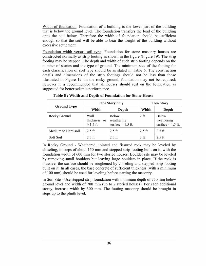
36
Width of foundation: Foundation of a building is the lower part of the building that is below the ground level. The foundation transfers the load of the building onto the soil below. Therefore the width of foundation should be sufficient enough so that the soil will be able to bear the weight of the building without excessive settlement.
Foundation width versus soil type: Foundation for stone masonry houses are constructed normally as strip footing as shown in the figure (Figure 19). The strip footing may be stepped. The depth and width of such strip footing depends on the number of stories and the type of ground. The minimum size of the footing for each classification of soil type should be as stated in Table 6. The construction details and dimensions of the strip footings should not be less than those illustrated in Figure 19. In the rocky ground, foundation may not be required; however it is recommended that all houses should rest on the foundation as suggested for better seismic performance.
Table 6 : Width and Depth of Foundation for Stone House
Ground Type One Story only Two Story
Width Depth Width Depth
Rocky Ground Wall thickness or ≥ 1.5 ft
Below weathering surface ≈ 1.5 ft.
2 ft Below weathering surface ≈ 1.5 ft.
Medium to Hard soil 2.5 ft 2.5 ft 2.5 ft 2.5 ft
Soft Soil 2.5 ft 2.5 ft 3 ft 2.5 ft
In Rocky Ground - Weathered, jointed and fissured rock may be leveled by chiseling, in steps of about 150 mm and stepped strip footing built on it, with the foundation width of 600 mm for two storied houses. Boulder site may be leveled by removing small boulders but leaving large boulders in place. If the rock is massive, the surface should be roughened by chiseling and stepped-strip footing built on it. In all cases, the base concrete of sufficient thickness (with a minimum of 100 mm) should be used for leveling before starting the masonry.
In Soil Site - Use stepped-strip foundation with minimum depth of 750 mm below ground level and width of 700 mm (up to 2 storied houses). For each additional storey, increase width by 300 mm. The footing masonry should be brought in steps up to the plinth level.
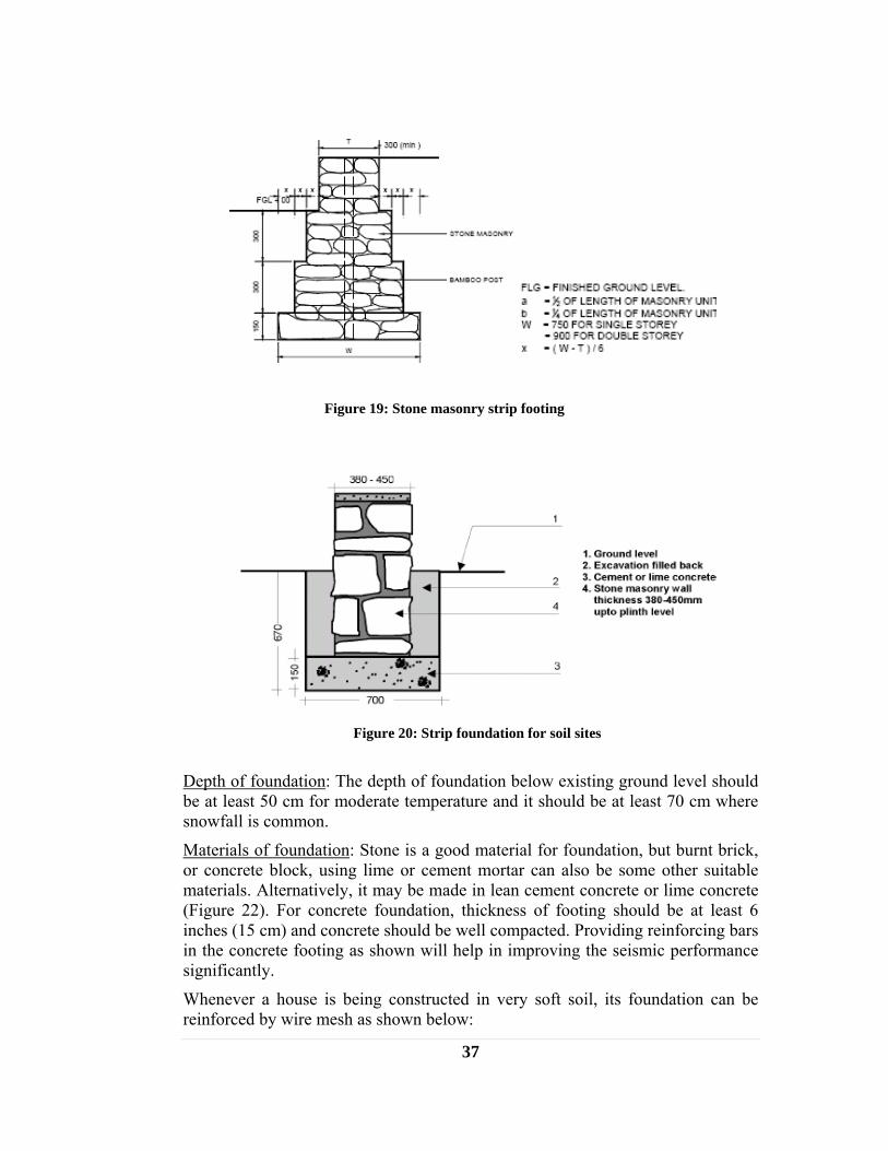
37
Figure 19: Stone masonry strip footing
Depth of foundation: The depth of foundation below existing ground level should be at least 50 cm for moderate temperature and it should be at least 70 cm where snowfall is common.
Materials of foundation: Stone is a good material for foundation, but burnt brick, or concrete block, using lime or cement mortar can also be some other suitable materials. Alternatively, it may be made in lean cement concrete or lime concrete (Figure 22). For concrete foundation, thickness of footing should be at least 6 inches (15 cm) and concrete should be well compacted. Providing reinforcing bars in the concrete footing as shown will help in improving the seismic performance significantly.
Whenever a house is being constructed in very soft soil, its foundation can be reinforced by wire mesh as shown below:
Figure 20: Strip foundation for soil sites

38
Use of Existing Old Foundation If there is possibility of using existing old foundation, it will be economically feasible to use such existing foundation. Houses of pre-damage dimensions and heights could be built on existing foundation constructed in stone laid in compacted sand or mud mortar. However, the existing foundation need to be excavated foundation may be excavated to about 230 mm below ground level where base concrete of 150 mm thick in 1:4:8 mix is to be cast on the existing lower part of the footing (Figure 32).
10.3.2 Plinth Masonry
The plinth masonry should also be constructed using stone. Cement mortar or lime mortar is stronger than mud mortar in binding the stones or bricks in the wall together to resist earthquake forces.
Height of plinth: The height of the plinth should be above the flood water line or a minimum of 1 ft (30 cm) above ground level.
10.3.3 Waterproofing and Drainage Water makes the foundation soil weak. In an area that experiences rainfall or snowfall, it is recommended to use a waterproofing layer at the plinth level before starting the construction of wall above the plinth and provide an apron and drain
Figure 23: Strip footing on existing foundation
Figure 21: Reinforcement of stone foundation
by wire mesh
Figure 22: Concrete Foundation

39
around the house to prevent runoff water that might wet walls or enter the foundation.
Figure 24: Drainage for protection of foundation
Apron and water drain: 90 to 120 cm wide aprons and a water drain should be constructed around the house to keep runoff water away from the walls and foundation. The walls can also be protected from rain by constructing roof projection and waterproof plastering on walls.
10.3.4 Treatment at plinth Treatment at plinth level is necessary to prevent the raise of moisture from the soil below to the superstructure walls. Treatment at plinth can be done by providing a band of concrete or by providing timber bands. Concrete band with reinforcement bars inside (Figure 25) will help in improving the seismic performance significantly. In rocky ground area reinforcement band may not be necessary but in soil site area reinforcement band should be provided. However, it is recommended to provide reinforced concrete band in all the areas for better seismic capacity.
10.3.5 Stone Masonry Walls in Mud Mortar A. Thickness, length and height of wall / building
• Thickness of stone masonry wall should be around 1.5 ft.
• Height of the coursed rubble masonry walls in mud mortar should be restricted with storey height to be kept maximum 2.7m, span of walls between
Figure 25: Reinforced Concrete Band as DPC Band

40
cross walls to be limited to 5.0 m and the number of stories preferably one story but not more than two stories in any case.
• If walls longer than 5m are needed, pilasters or buttresses may be used at intermediate points not farther apart than 3.5m. The size of the pilaster or buttress are to be kept of uniform thickness with top width equal to the thickness of main wall `t’ and the base width equal to t or one sixth of wall height (Figure 26).
Figure 26: Unsupported length of stone walls
B. Appropriate size and location of openings
For the stone masonry wall built in mud mortar, door and window openings may be located in the walls as follows:
• Total length of openings in a wall = 0.33 of wall length or one third (1/3) of the total wall length
• Distance of opening from inside corner: b5 > 2 ft. (600 mm)
• Pier width between consecutive openings > 2 ft. (600mm)
Figure 27: Size and location of door and window openings

41
C. Good Quality of Stone masonry laying
• The thickness of walls should preferably be 1.5 ft (450mm). The stones of the inner and outer wythes should be interlocked with each other as far as possible.
• The masonry should preferably be brought to courses at not more than 2 ft. (600 mm) lift so as to achieve `coursed rubble masonry’.
• `Through’ stones of full length equal to wall thickness should be used in every 2 ft. (600 mm) lift at not more than 4 ft (1.2m) apart horizontally (Figure 37).
• In place of `through’ stones, `bonding elements’ of concrete bars of 50mm x 50mm section with an 8mm dia. rod placed centrally or solid concrete blocks of 150 x 150 x `wall thickness size’ may be used. (Figure 37). Alternatively, tree branches of 60 mm dia, or seasoned wooden battens of 50 mm x 50 mm size may be used as bonding element.
• Long stones of 2 ft (600 mm) length or solid concrete blocks of 150 x 150 x 600 mm size should be used at wall corners and T-junctions every 600 mm height to connect the perpendicular walls effectively (Figure 37 and 38). Alternatively, branches of 65 mm dia., or seasoned wooden batten of 60 mm x 60 mm size may be used.
• The mortar should be clay mud of good quality.
Figure 28: Layout of thorough stones in stone walls

42
D. Horizontal seismic bands
To improve integrity, strength, and ductility of masonry house, its walls have to be reinforced horizontally and vertically. Vertical reinforcement helps to tie the walls to the foundation, and horizontal reinforcements help restrain out-of-plane bending and improve in-plane shear. Horizontal reinforcement helps to transmit the bending and inertia forces of transverse walls (out-of-plane) to the supporting shear walls (in-plane), as well as restraining the shear stresses between adjoining walls and minimizing vertical crack propagation. The horizontal and vertical reinforcement should be tied together and to the other structural elements (foundations, ring beam, roof). Placement of reinforcement must be carefully planned. Any ductile material such as bamboo, reeds, cane, vines, rope, timber, chicken wire, welded steel mesh, or steel bars can be used for reinforcement. Out of such strengthening measures horizontal seismic bands are discussed below.
A seismic band is a continuous beam that binds and reinforces orthogonal walls together. The seismic bands should be provided at the levels of plinth, lintel, floor and eaves. If possible, one seismic band should be provided at sill level also. The overall arrangement of seismic reinforcing of masonry buildings is shown in Figure 30. The seismic bands at various critical sections should be as follows:
1. Seismic bands at plinth, lintel, ceiling levels in buildings with flat roof will be provided in all internal and external walls continuously without break in all stories.
2. In case of sloping roofs, triangular gable walls must also be enclosed within eave level band and a band at the top of the gable wall.
3. The bands can be made of reinforced concrete sections as mentioned in the following section “stone masonry in cement mortar” or in case of stone
Figure 29: Construction details of stone masonry wall
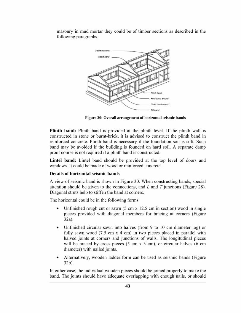
43
masonry in mud mortar they could be of timber sections as described in the following paragraphs.
Plinth band: Plinth band is provided at the plinth level. If the plinth wall is constructed in stone or burnt-brick, it is advised to construct the plinth band in reinforced concrete. Plinth band is necessary if the foundation soil is soft. Such band may be avoided if the building is founded on hard soil. A separate damp proof course is not required if a plinth band is constructed.
Lintel band: Lintel band should be provided at the top level of doors and windows. It could be made of wood or reinforced concrete.
Details of horizontal seismic bands A view of seismic band is shown in Figure 30. When constructing bands, special attention should be given to the connections, and L and T junctions (Figure 28). Diagonal struts help to stiffen the band at corners.
The horizontal could be in the following forms:
• Unfinished rough cut or sawn (5 cm x 12.5 cm in section) wood in single pieces provided with diagonal members for bracing at corners (Figure 32a).
• Unfinished circular sawn into halves (from 9 to 10 cm diameter log) or fully sawn wood (7.5 cm x 4 cm) in two pieces placed in parallel with halved joints at corners and junctions of walls. The longitudinal pieces will be braced by cross pieces (5 cm x 3 cm), or circular halves (6 cm diameter) with nailed joints.
• Alternatively, wooden ladder form can be used as seismic bands (Figure 32b).
In either case, the individual wooden pieces should be joined properly to make the band. The joints should have adequate overlapping with enough nails, or should
Figure 30: Overall arrangement of horizontal seismic bands

44
be connected with iron-straps with sufficient nails/ screws to ensure the strength of the original wood at the joint. For enhancing durability, it is desirable to use seasoned wood. Chemical treatment against termite attack further enhances durability of the wood.
Figure 31: Isometric view of wooden seismic band in stone wall
Figure 32: Details of timber band
a) Rough cut lumber in single piece
b) Rough cut lumber in two parallel
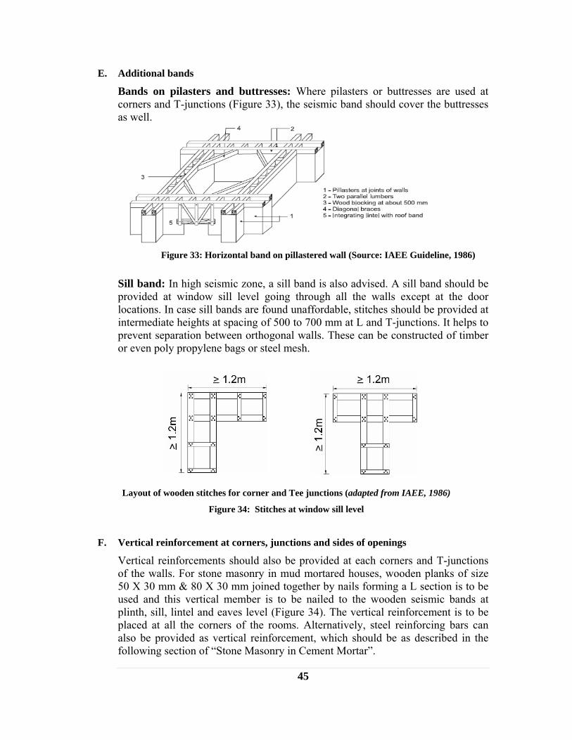
45
E. Additional bands
Bands on pilasters and buttresses: Where pilasters or buttresses are used at corners and T-junctions (Figure 33), the seismic band should cover the buttresses as well.
Sill band: In high seismic zone, a sill band is also advised. A sill band should be provided at window sill level going through all the walls except at the door locations. In case sill bands are found unaffordable, stitches should be provided at intermediate heights at spacing of 500 to 700 mm at L and T-junctions. It helps to prevent separation between orthogonal walls. These can be constructed of timber or even poly propylene bags or steel mesh.
Layout of wooden stitches for corner and Tee junctions (adapted from IAEE, 1986)
Figure 34: Stitches at window sill level
F. Vertical reinforcement at corners, junctions and sides of openings
Vertical reinforcements should also be provided at each corners and T-junctions of the walls. For stone masonry in mud mortared houses, wooden planks of size 50 X 30 mm & 80 X 30 mm joined together by nails forming a L section is to be used and this vertical member is to be nailed to the wooden seismic bands at plinth, sill, lintel and eaves level (Figure 34). The vertical reinforcement is to be placed at all the corners of the rooms. Alternatively, steel reinforcing bars can also be provided as vertical reinforcement, which should be as described in the following section of “Stone Masonry in Cement Mortar”.
Figure 33: Horizontal band on pillastered wall (Source: IAEE Guideline, 1986)

46
Figure 35: Vertical reinforcement of stone wall
10.3.6 Stone Masonry Walls in Cement Mortar A. Thickness, length and height of wall / building
• The height of the stone masonry walls in cement mortar should be restricted to two stories with flat roof or one story plus attic for pitched roof.
• The storey height to be kept 3.2m maximum, and span of walls between cross walls to be limited to 7.0m. If rooms longer than 7m are needed, buttresses may be used at intermediate points not farther apart than 5.0m. The size of the buttress be kept of uniform thickness with top width equal to the thickness of main wall and the base width equal to one sixth of wall height.
B. Appropriate size and location of openings
For stone masonry built in cement mortar and brought to courses, the door and window openings should be controlled as follows (Figure 45):
Ratio of total length of openings in a wall to length of the wall in a room should not exceed 0.5 in single storied, 0.42 in 2-storeyed and 0.33 in 3 storied buildings.
• Distance of opening from inside corner ≥ 450mm
• Pier width between consecutive openings ≥ 600mm
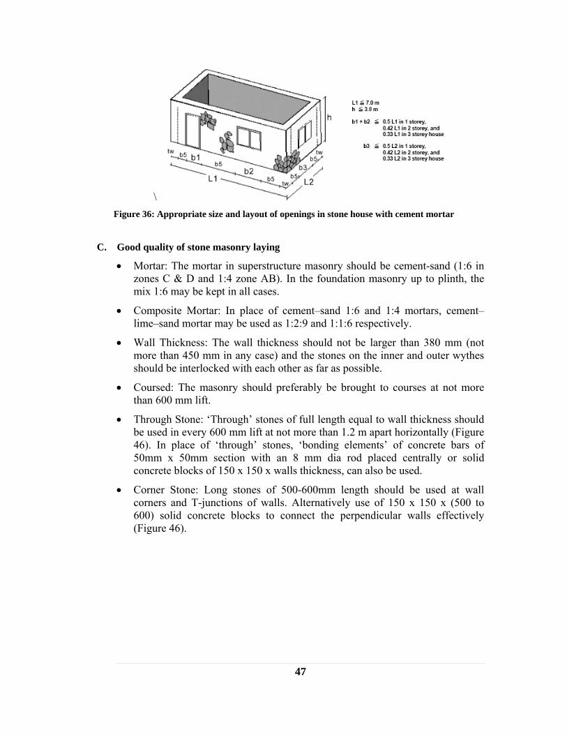
47
\ Figure 36: Appropriate size and layout of openings in stone house with cement mortar
C. Good quality of stone masonry laying
• Mortar: The mortar in superstructure masonry should be cement-sand (1:6 in zones C & D and 1:4 zone AB). In the foundation masonry up to plinth, the mix 1:6 may be kept in all cases.
• Composite Mortar: In place of cement–sand 1:6 and 1:4 mortars, cement–lime–sand mortar may be used as 1:2:9 and 1:1:6 respectively.
• Wall Thickness: The wall thickness should not be larger than 380 mm (not more than 450 mm in any case) and the stones on the inner and outer wythes should be interlocked with each other as far as possible.
• Coursed: The masonry should preferably be brought to courses at not more than 600 mm lift.
• Through Stone: ‘Through’ stones of full length equal to wall thickness should be used in every 600 mm lift at not more than 1.2 m apart horizontally (Figure 46). In place of ‘through’ stones, ‘bonding elements’ of concrete bars of 50mm x 50mm section with an 8 mm dia rod placed centrally or solid concrete blocks of 150 x 150 x walls thickness, can also be used.
• Corner Stone: Long stones of 500-600mm length should be used at wall corners and T-junctions of walls. Alternatively use of 150 x 150 x (500 to 600) solid concrete blocks to connect the perpendicular walls effectively (Figure 46).

48
Figure 37: Through stones and bond blocks for stone in cement walls
D. Seismic bands at different locations
The overall arrangement of seismic bands will be same as that mentioned earlier in the stone masonry on mud mortar. However, in cement mortar building, the seismic bands should be reinforced concrete sections as shown in detail below:
For achieving good bond with masonry, the bands should be cast directly on the masonry and its top surface should be made rough. In the case of plinth and lintel band, stones may be cast in the concrete to project out of the concrete by 50 to 75mm.
Figure 38: Section details of RCC band
Figure 39: RC Band Reinforcement detail at corners and junctions
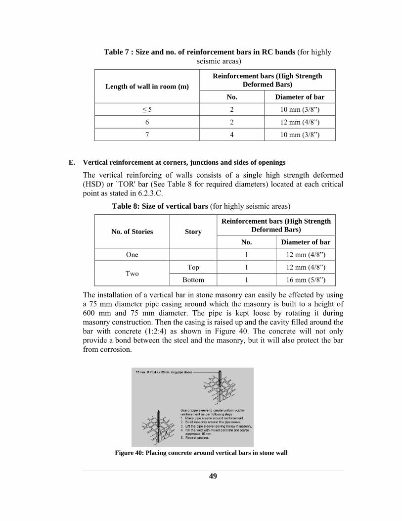
49
Table 7 : Size and no. of reinforcement bars in RC bands (for highly seismic areas)
Length of wall in room (m) Reinforcement bars (High Strength
Deformed Bars)
No. Diameter of bar
≤ 5 2 10 mm (3/8”)
6 2 12 mm (4/8”)
7 4 10 mm (3/8”)
E. Vertical reinforcement at corners, junctions and sides of openings
The vertical reinforcing of walls consists of a single high strength deformed (HSD) or `TOR' bar (See Table 8 for required diameters) located at each critical point as stated in 6.2.3.C.
Table 8: Size of vertical bars (for highly seismic areas)
No. of Stories Story Reinforcement bars (High Strength
Deformed Bars)
No. Diameter of bar
One 1 12 mm (4/8”)
Two Top 1 12 mm (4/8”)
Bottom 1 16 mm (5/8”)
The installation of a vertical bar in stone masonry can easily be effected by using a 75 mm diameter pipe casing around which the masonry is built to a height of 600 mm and 75 mm diameter. The pipe is kept loose by rotating it during masonry construction. Then the casing is raised up and the cavity filled around the bar with concrete (1:2:4) as shown in Figure 40. The concrete will not only provide a bond between the steel and the masonry, but it will also protect the bar from corrosion.
Figure 40: Placing concrete around vertical bars in stone wall
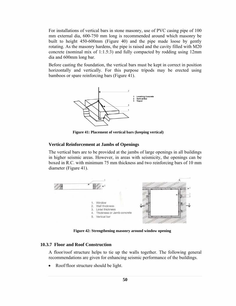
50
For installations of vertical bars in stone masonry, use of PVC casing pipe of 100 mm external dia, 600-750 mm long is recommended around which masonry be built to height 450-600mm (Figure 40) and the pipe made loose by gently rotating. As the masonry hardens, the pipe is raised and the cavity filled with M20 concrete (nominal mix of 1:1.5:3) and fully compacted by rodding using 12mm dia and 600mm long bar.
Before casting the foundation, the vertical bars must be kept in correct in position horizontally and vertically. For this purpose tripods may be erected using bamboos or spare reinforcing bars (Figure 41).
Vertical Reinforcement at Jambs of Openings The vertical bars are to be provided at the jambs of large openings in all buildings in higher seismic areas. However, in areas with seismicity, the openings can be boxed in R.C. with minimum 75 mm thickness and two reinforcing bars of 10 mm diameter (Figure 41).
10.3.7 Floor and Roof Construction A floor/roof structure helps to tie up the walls together. The following general recommendations are given for enhancing seismic performance of the buildings.
• Roof/floor structure should be light.
Figure 41: Placement of vertical bars (keeping vertical)
Figure 42: Strengthening masonry around window opening
51
• The floor joist, or roof beams or rafters should rest on a wall plate, preferably on the seismic bands at floor or eaves level. The joists and rafters should be well tied to the bands with nails or galvanized wire.
• Care should be taken to avoid placement of the floor joist, or roof beams or rafters just above door or window openings. Otherwise, the lintel band should be additionally reinforced as mentioned in Chapter 8.
• The floor/ roof structure should be braced to improve integrity and stiffness.
• In high rainfall areas, large roof overhang should be provided to protect walls from wetting.

52
11 TIMBER HOUSE Wooden construction has been regarded as one of the most suitable earthquake-resistant construction for residential houses since timber has higher strength per unit weight. However, its earthquake performance highly depends on the joints between different structural elements and the type and quality of infill between wooden elements. Hence, while constructing timber houses the joints should be made properly. Timber houses should be less than two storied.
11.1 DIFFERENT TYPES OF WOODEN WALL CONSTRUCTION
11.1.1 Stud Wall Construction The stud-wall construction consists of timber studs and corner posts framed into sills, top plates and wall plates. Horizontal struts and diagonal braces are used to stiffen the frame against lateral loads due to earthquake and wind. The wall covering may consist of matting made from bamboo, reeds, and timber boarding or the like. Typical details of stud walls are shown in Figure 43. If the sheathing boards are properly nailed to the timber frame, the diagonal bracing may be omitted. The diagonal bracing may be framed into the verticals, or nailed to the surface. Other details are given below:
11.1.2 Details of stud wall construction Sill
The dimension of sill is kept 40 × 90, 90 × 90 (mm units) or larger. The sill is connected to the foundation by anchor bolts whose minimum diameter is 12 mm and length 35 cm. The anchor bolts are installed at both sides of joints of sills and at the maximum spacing is 2 m.
Figure 43: View of stud wall construction

53
Studs
The minimum dimension of studs is 40 mm × 90 mm. If 90 mm × 90 mm studs are used the spacing may be doubled. Storey height should not be more than 2.70 m. Top plates
The top of studs is connected to top plates whose dimension is not less than the dimension of the stud.
Bearing walls Wall framing consisting of sills, studs and top plates should have diagonal braces, or sheathing boards so that the framings acts as bearing walls. In case no sheathing boards are attached, all studs should be connected to the adjacent studs by horizontal blockings at least every 1.5 m in height, Figure 44. The minimum dimension of braces is 20 mm × 60 mm. The brace is fastened at both ends and at middle portion by more than two nails whose minimum length is 50 mm to the framing members. The sheathing board is connected to the framing members by nails whose minimum length is 50 mm and maximum spacing is 150 mm at the fringe of the board and 300 mm at other parts.
11.1.3 Brick or Stone Nogged Timber Frame Construction The brick nogged timber frame consists of intermediate verticals, columns, sills, wall plates, horizontal nogging members framed into each other. Diagonal braces may also be framed with the verticals or nailed or bolted on the faces. The space between framing members is filled with tight fitting brick or dressed stone masonry in stretcher bond.
Typical details of brick nogged timber frame construction are shown in Figure 44.
Figure 44: Brick nogged timber frame construction
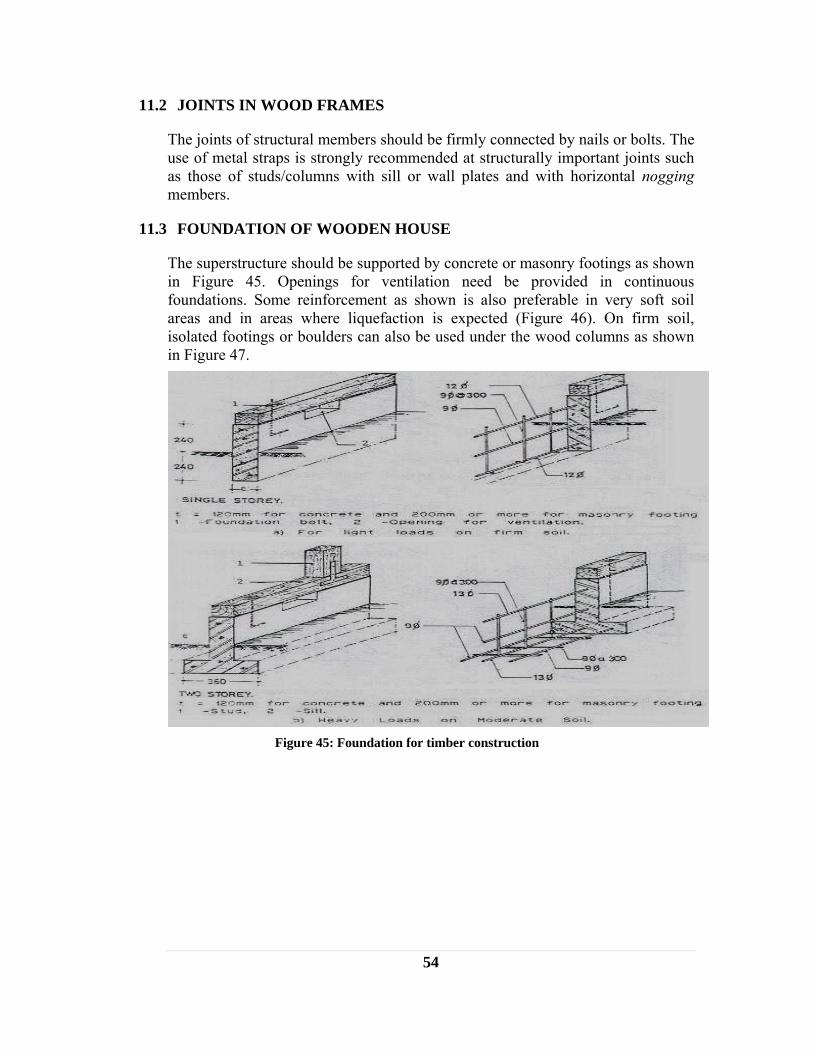
54
11.2 JOINTS IN WOOD FRAMES
The joints of structural members should be firmly connected by nails or bolts. The use of metal straps is strongly recommended at structurally important joints such as those of studs/columns with sill or wall plates and with horizontal nogging members.
11.3 FOUNDATION OF WOODEN HOUSE
The superstructure should be supported by concrete or masonry footings as shown in Figure 45. Openings for ventilation need be provided in continuous foundations. Some reinforcement as shown is also preferable in very soft soil areas and in areas where liquefaction is expected (Figure 46). On firm soil, isolated footings or boulders can also be used under the wood columns as shown in Figure 47.
Figure 45: Foundation for timber construction
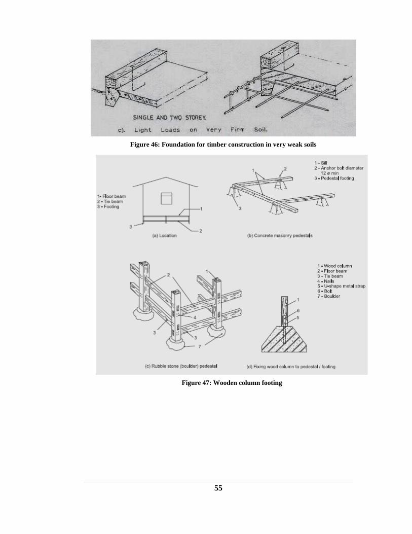
55
Figure 46: Foundation for timber construction in very weak soils
Figure 47: Wooden column footing
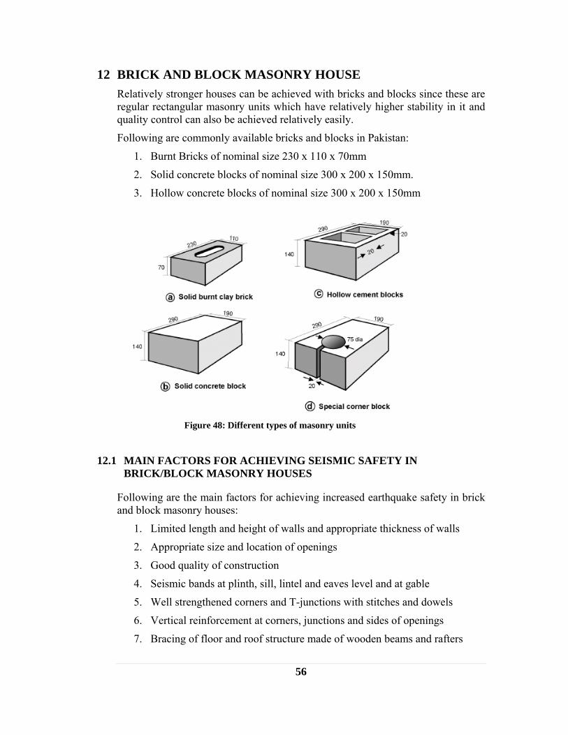
56
12 BRICK AND BLOCK MASONRY HOUSE Relatively stronger houses can be achieved with bricks and blocks since these are regular rectangular masonry units which have relatively higher stability in it and quality control can also be achieved relatively easily.
Following are commonly available bricks and blocks in Pakistan:
1. Burnt Bricks of nominal size 230 x 110 x 70mm
2. Solid concrete blocks of nominal size 300 x 200 x 150mm.
3. Hollow concrete blocks of nominal size 300 x 200 x 150mm
12.1 MAIN FACTORS FOR ACHIEVING SEISMIC SAFETY IN BRICK/BLOCK MASONRY HOUSES
Following are the main factors for achieving increased earthquake safety in brick and block masonry houses:
1. Limited length and height of walls and appropriate thickness of walls
2. Appropriate size and location of openings
3. Good quality of construction
4. Seismic bands at plinth, sill, lintel and eaves level and at gable
5. Well strengthened corners and T-junctions with stitches and dowels
6. Vertical reinforcement at corners, junctions and sides of openings
7. Bracing of floor and roof structure made of wooden beams and rafters
Figure 48: Different types of masonry units

57
12.2 CONSTRUCTION OF BRICK MASONRY HOUSE IN MUD OR CEMENT MORTAR
Main features for making brick masonry buildings whether they are in mud mortar or are in cement mortar are same. However, relative seismic safety of these buildings differ, the cement mortared building being much safer one. Therefore, the permissible height of these two types of buildings as well as heights, thickness, length of individual walls differs. Following table gives the length and height of walls and the building:
Table 8: Thickness and height of brick masonry walls
Type of wall construction
Max. no. of stories
Story Min. Thickness of
wall (mm)
Height if individual wall (m)
Brick Masonry in Mud Mortar
2 Ground 350 3.2
First 350 3.0
Brick Masonry in Cement Mortar
3 Ground 350 3.2
First 230 3.0
Second 230 2.8
12.2.1 Foundation Foundation for masonry building should be of strip footing as shown in Figure 58.
Footing for Brick masonry in cement mortar
Figure 49: Foundation for one story building

58
Following size of foundation is recommended for different cases:
Table 9 : Size of foundation footing
Type of Building For one story only
For Storied (or upto 3 storied for brick in
cement)
Width Height Width Height
Brick masonry in mud mortar
900 mm (3 ft)
800 mm (2.5 ft)
1000mm (3.3 ft)
1000mm (3.3 ft)
Brick Masonry in Cement mortar
900 mm (3 ft)
800 mm (2.5 ft)
900 mm (3 ft)
900 mm (3 ft)
All other construction details and treatment for brick masonry foundation are similar to those for foundation of stone masonry houses. Further, the foundation for brick masonry building may be of stone masonry footing as detailed in chapter 7.
12.2.2 Wall Construction A. Length and Height of Walls
• When cement mortar is used with masonry units, the wall height from floor to ceiling should not exceed 15 times the wall thickness, and the length between cross-walls in a room should be less than 35 times the wall thickness but not larger than 8.0m.
• For houses, room height and length should preferably be restricted to 2.7m and 5.0m respectively in hilly areas and 3.2m and 6.0mm in plain areas.
• If above constraints are not met, either the wall thickness should be increased or appropriately designed intermediate columns, pilasters or buttresses should be provided to take care of the lateral seismic force.
B. Appropriate size and location of openings
Any opening in the wall should be small in size and centrally located. Following are the guidelines for size and position of openings (Figure 50).
• Openings are to be located away from inside corners by a clear distance equal to at least 1/4 of the height of the opening, but not less than 600 mm.
• The total length of openings in a wall are not to exceed 50 % of the length of the wall between consecutive cross-walls in single-story construction, 42 % in two-story construction, and 33 % in three-story buildings.
• The horizontal distance (pier width) between two openings is to be not less than one half of the height of the shorter opening, but not less than 600 mm.
• The vertical distance from one opening to another opening directly above it should not be less than 600 mm, nor less than one half the width of the smaller opening.

59
• When an opening does not comply with above, it should be boxed in reinforced jambs through the masonry as shown in Figure 51.
• If the vertical opening of the wall is more than 50 % of the wall height, vertical bars should be provided in the jambs.
Figure 51: Strengthening of masonry around openings
Figure 50: Size and location of openings in brick wall with cement mortar

60
If the wall is constructed with mud mortar the recommendation for openings is different than that with cement mortar. The openings should be as shown in Figure 52.
12.2.3 Good quality of construction A. Good quality materials and brick laying
Good quality of materials and construction is the key to strength and durability of masonry as well as safer seismic performance. The following control measures will be significant for selection of good materials and good quality construction:
Bricks: The bricks should be of a standard rectangular shape, burnt red, hand-formed or machine-made. The higher the density and the strength, the better they will be. The standard brick size of 240 × 115 x 57 mm with 10 mm thick horizontal and vertical mortar joints is preferable. Tolerances of -10 mm on length, -5 mm on width and ± 3 mm on thickness are acceptable for the purpose of walls of the thickness specified in this Standard.
Wall Thickness: A minimum thickness of one half-brick (115 mm) and a maximum thickness of one brick (240 mm) should be used for the walls constructed as non load-bearing walls in these buildings.
Mortar: Cement-sand mixes of 1:6 and 1:4 should be adopted for one-brick and half-brick thick walls, respectively. The addition of small quantities of freshly hydrated lime to the mortar in a lime-cement ratio of ¼:1 to ½:1 will increase its plasticity greatly without reducing its strength.
Figure 52: Openings in brick wall with mud mortar
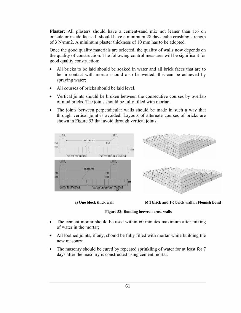
61
Plaster: All plasters should have a cement-sand mix not leaner than 1:6 on outside or inside faces. It should have a minimum 28 days cube crushing strength of 3 N/mm2. A minimum plaster thickness of 10 mm has to be adopted.
Once the good quality materials are selected, the quality of walls now depends on the quality of construction. The following control measures will be significant for good quality construction:
• All bricks to be laid should be soaked in water and all brick faces that are to be in contact with mortar should also be wetted; this can be achieved by spraying water;
• All courses of bricks should be laid level.
• Vertical joints should be broken between the consecutive courses by overlap of mud bricks. The joints should be fully filled with mortar.
• The joints between perpendicular walls should be made in such a way that through vertical joint is avoided. Layouts of alternate courses of bricks are shown in Figure 53 that avoid through vertical joints.
a) One block thick wall b) 1 brick and 1½ brick wall in Flemish Bond
Figure 53: Bonding between cross walls
• The cement mortar should be used within 60 minutes maximum after mixing of water in the mortar;
• All toothed joints, if any, should be fully filled with mortar while building the new masonry;
• The masonry should be cured by repeated sprinkling of water for at least for 7 days after the masonry is constructed using cement mortar.

62
B. Masonry Bond
In order to achieve the full strength of masonry, the usual bonds specified for masonry should be followed so that the vertical joints are broken properly from course to course.
Burnt bricks are normally used in English bond (Figure 54a) giving wall thickness of 100 - 114 mm for partition walls to be built in 1:4 cement-sand mortar; and 200 - 230 or 300 - 340 mm for load bearing walls.
For one storied lower cost houses, walls may be built using Rat-trap bond (Figure 54b) with Mortar of 1:4 mix. This will save about 25% of bricks and provide better thermal insulation also.
Figure 54: Bonds in brick masonry wall construction

63
C. Joints between orthogonal walls
For convenience of construction, builders prefer to make a toothed joint which is many times left hollow and weak. To obtain full bond it is necessary to make a sloping (stepped) joint by making the corners first to a height of 600 mm and then building the wall in between them (Figure 55). Otherwise, the toothed joint should be made in both the walls alternately in lifts of about 45 cm (Figure 56).
To further strengthen the connection between transverse walls, steel dowel bars as described in section 8.2.5 may be used at corners and T-junctions to enhance the box action of walls.
12.2.4 Horizontal seismic bands at different levels A continuous band, also called 'ring beam' or ‘collar beam’ is a RC band or runner provided at different levels in all walls of the building for tying walls together to enhance box action. It improves horizontal bending resistance thereby preventing out-of-plane collapse of walls.
Figure 56: Alternate toothing joints in wall corners
Figure 55: Stepped joint construction
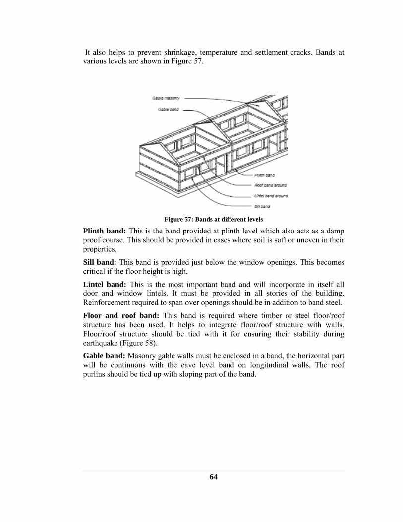
64
It also helps to prevent shrinkage, temperature and settlement cracks. Bands at various levels are shown in Figure 57.
Plinth band: This is the band provided at plinth level which also acts as a damp proof course. This should be provided in cases where soil is soft or uneven in their properties.
Sill band: This band is provided just below the window openings. This becomes critical if the floor height is high.
Lintel band: This is the most important band and will incorporate in itself all door and window lintels. It must be provided in all stories of the building. Reinforcement required to span over openings should be in addition to band steel.
Floor and roof band: This band is required where timber or steel floor/roof structure has been used. It helps to integrate floor/roof structure with walls. Floor/roof structure should be tied with it for ensuring their stability during earthquake (Figure 58).
Gable band: Masonry gable walls must be enclosed in a band, the horizontal part will be continuous with the eave level band on longitudinal walls. The roof purlins should be tied up with sloping part of the band.
Figure 57: Bands at different levels
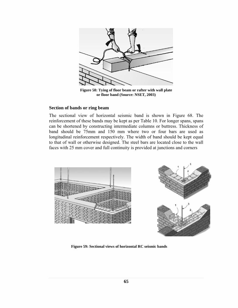
65
Section of bands or ring beam The sectional view of horizontal seismic band is shown in Figure 68. The reinforcement of these bands may be kept as per Table 10. For longer spans, spans can be shortened by constructing intermediate columns or buttress. Thickness of band should be 75mm and 150 mm where two or four bars are used as longitudinal reinforcement respectively. The width of band should be kept equal to that of wall or otherwise designed. The steel bars are located close to the wall faces with 25 mm cover and full continuity is provided at junctions and corners
Figure 59: Sectional views of horizontal RC seismic bands
Figure 58: Tying of floor beam or rafter with wall plate
or floor band (Source: NSET, 2003)
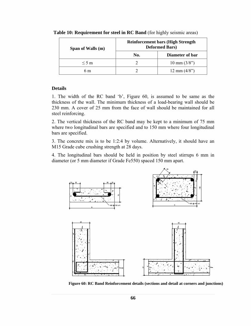
66
Table 10: Requirement for steel in RC Band (for highly seismic areas)
Span of Walls (m) Reinforcement bars (High Strength
Deformed Bars)
No. Diameter of bar
≤ 5 m 2 10 mm (3/8”)
6 m 2 12 mm (4/8”)
Details 1. The width of the RC band ‘b’, Figure 60, is assumed to be same as the thickness of the wall. The minimum thickness of a load-bearing wall should be 230 mm. A cover of 25 mm from the face of wall should be maintained for all steel reinforcing.
2. The vertical thickness of the RC band may be kept to a minimum of 75 mm where two longitudinal bars are specified and to 150 mm where four longitudinal bars are specified.
3. The concrete mix is to be 1:2:4 by volume. Alternatively, it should have an M15 Grade cube crushing strength at 28 days.
4. The longitudinal bars should be held in position by steel stirrups 6 mm in diameter (or 5 mm diameter if Grade Fe550) spaced 150 mm apart.
Figure 60: RC Band Reinforcement details (sections and detail at corners and junctions)

67
In case of brick masonry in mud mortar the seismic bands could be of timber sections as mentioned in the construction of stone masonry buildings.
The lintel band can be avoided if the height of the wall is less than 2.5 m, however, in such cases; the individual lintels should be connected to the ceiling band at the levels of floor, eaves, or roof, as shown in Figure 61.
When individual lintels are provided above doors or windows, the bearing length of the lintel should not be less than 50cm in order to transfer the load to the wall without unduly stressing it.
Placement of floor/roof beam directly above the lintel should be avoided. If it is not possible, the lintel should be strengthened by providing an additional reinforcing lintel (Figure 62).
12.2.5 Well strengthened corners and T-junctions with stitches and dowels As a supplement to the bands described above, steel dowel bars may be used at corners and T-junctions to integrate the box action of walls (Figure 63, 64 and 65). Dowels are placed in every fourth course or at about 50 cm intervals and taken into the walls to sufficient length so as to provide the full bond strength. Wooden dowels can also be used instead of steel. However, the dowels do not serve to reinforce the walls in horizontal bending except near the junctions.
Figure 62: Strengthening of Lintel Band (adapted from IAEE, 1986)
Figure 61: Connection of isolated lintel to eaves or roof
level band

68
Figure 64: Strengthening with dowel reinforcement and welded wire
Figure 63: Corner strengthening by dowel reinforcement
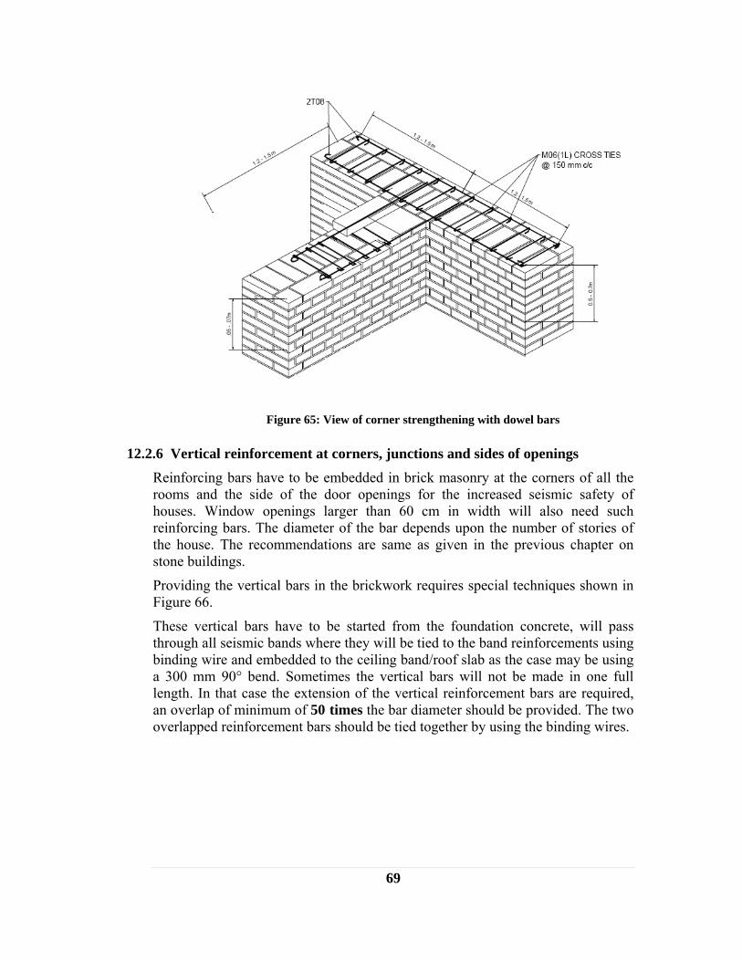
69
12.2.6 Vertical reinforcement at corners, junctions and sides of openings Reinforcing bars have to be embedded in brick masonry at the corners of all the rooms and the side of the door openings for the increased seismic safety of houses. Window openings larger than 60 cm in width will also need such reinforcing bars. The diameter of the bar depends upon the number of stories of the house. The recommendations are same as given in the previous chapter on stone buildings.
Providing the vertical bars in the brickwork requires special techniques shown in Figure 66.
These vertical bars have to be started from the foundation concrete, will pass through all seismic bands where they will be tied to the band reinforcements using binding wire and embedded to the ceiling band/roof slab as the case may be using a 300 mm 90° bend. Sometimes the vertical bars will not be made in one full length. In that case the extension of the vertical reinforcement bars are required, an overlap of minimum of 50 times the bar diameter should be provided. The two overlapped reinforcement bars should be tied together by using the binding wires.
Figure 65: View of corner strengthening with dowel bars

70
12.3 CONSTRUCTION OF BLOCK MASONRY BUILDINGS
12.3.1 Types of concrete blocks Two types of cement concrete blocks are commonly used:
1. Solid concrete blocks of nominal size 300 X 200 X 150 mm (actual size 290 X 190 X or 200 X 140 mm)
2. Hollow concrete blocks of nominal size 300 X 200 X 150 mm
A. Use of solid concrete block
1. Using the concrete blocks of 300 X 200 X 150 mm nominal size, non-load bearing walls of 150 mm thickness and bearing walls of 200 mm thickness could be built. The bearing surfaces of the blocks should be made rough by the casting procedure to develop good bond with the mortar.
Figure 66: Vertical reinforcement bars at corners and junctions
(a) – Hollow Concrete block (b) – Solid Concrete Block
Figure 67: Types of concrete blocks
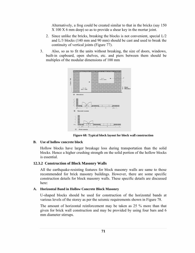
71
Alternatively, a frog could be created similar to that in the bricks (say 150 X 100 X 6 mm deep) so as to provide a shear key in the mortar joint.
2. Since unlike the bricks, breaking the blocks is not convenient, special L/2 and L/3 blocks (140 mm and 90 mm) should be cast and used to break the continuity of vertical joints (Figure 77).
3. Also, so as to fit the units without breaking, the size of doors, windows, built-in cupboard, open shelves, etc. and piers between them should be multiples of the modular dimensions of 100 mm
B. Use of hollow concrete block
Hollow blocks have larger breakage loss during transportation than the solid blocks. Hence a higher crushing strength on the solid portion of the hollow blocks is essential.
12.3.2 Construction of Block Masonry Walls All the earthquake-resisting features for block masonry walls are same to those recommended for brick masonry buildings. However, there are some specific construction details for block masonry walls. These specific details are discussed here:
A. Horizontal Band in Hollow Concrete Block Masonry
U-shaped blocks should be used for construction of the horizontal bands at various levels of the storey as per the seismic requirements shown in Figure 78.
The amount of horizontal reinforcement may be taken as 25 % more than that given for brick wall construction and may be provided by using four bars and 6 mm diameter stirrups.
Figure 68: Typical block layout for block wall construction
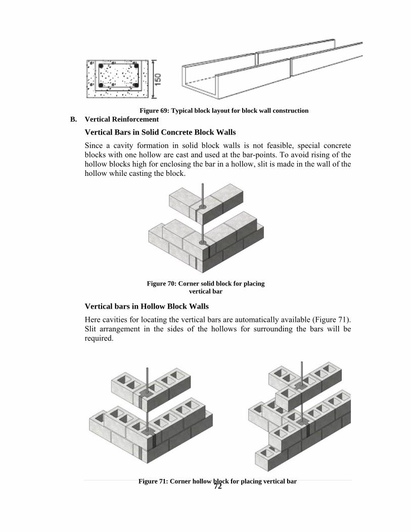
72
B. Vertical Reinforcement
Vertical Bars in Solid Concrete Block Walls Since a cavity formation in solid block walls is not feasible, special concrete blocks with one hollow are cast and used at the bar-points. To avoid rising of the hollow blocks high for enclosing the bar in a hollow, slit is made in the wall of the hollow while casting the block.
Vertical bars in Hollow Block Walls Here cavities for locating the vertical bars are automatically available (Figure 71). Slit arrangement in the sides of the hollows for surrounding the bars will be required.
Figure 69: Typical block layout for block wall construction
Figure 70: Corner solid block for placing
vertical bar
Figure 71: Corner hollow block for placing vertical bar
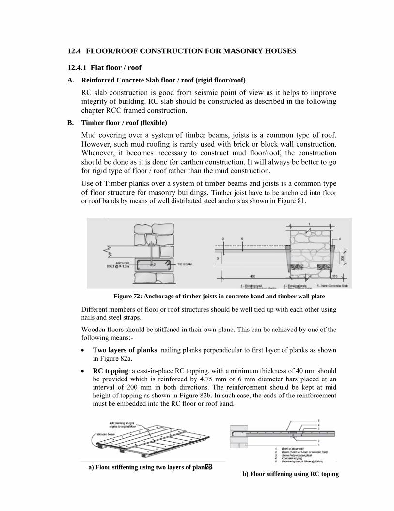
73
12.4 FLOOR/ROOF CONSTRUCTION FOR MASONRY HOUSES
12.4.1 Flat floor / roof A. Reinforced Concrete Slab floor / roof (rigid floor/roof)
RC slab construction is good from seismic point of view as it helps to improve integrity of building. RC slab should be constructed as described in the following chapter RCC framed construction.
B. Timber floor / roof (flexible)
Mud covering over a system of timber beams, joists is a common type of roof. However, such mud roofing is rarely used with brick or block wall construction. Whenever, it becomes necessary to construct mud floor/roof, the construction should be done as it is done for earthen construction. It will always be better to go for rigid type of floor / roof rather than the mud construction.
Use of Timber planks over a system of timber beams and joists is a common type of floor structure for masonry buildings. Timber joist have to be anchored into floor or roof bands by means of well distributed steel anchors as shown in Figure 81.
Different members of floor or roof structures should be well tied up with each other using nails and steel straps.
Wooden floors should be stiffened in their own plane. This can be achieved by one of the following means:-
• Two layers of planks: nailing planks perpendicular to first layer of planks as shown in Figure 82a.
• RC topping: a cast-in-place RC topping, with a minimum thickness of 40 mm should be provided which is reinforced by 4.75 mm or 6 mm diameter bars placed at an interval of 200 mm in both directions. The reinforcement should be kept at mid height of topping as shown in Figure 82b. In such case, the ends of the reinforcement must be embedded into the RC floor or roof band.
Figure 72: Anchorage of timber joists in concrete band and timber wall plate
a) Floor stiffening using two layers of planks
b) Floor stiffening using RC toping

74
Figure 73: Floor stiffening using two layers of planks and using RC toping
• Bracing: floors or flat roof can be stiffened by nailing diagonal wooden or steel straps or angles from underside of joist or rafter as shown in Figure 74.
12.4.2 Sloped roof with timber /steel structure and CGI sheet covering (flexible) Pitched/sloped roofs may be trussed, with the top of the walls generally at one level - except for the masonry gables at the ends of the building. Alternatively, the longitudinal and cross-walls may be raised to varying heights up to the roof slope and the rooms spanned by rafters and purlins. From a seismic design point of view, the trussed arrangement is preferable, particularly for school buildings.
A. Trussed Roof with cement wall construction
In trussed roofs, all trusses should be supported on the eave or roof-band. Where a trussed roof adjoins a masonry gable, the ends of the purlins should be carried on and secured to a plate securely bolted to the band at the top of gable-end masonry (Figure 75 and 76).
Figure 74: Floor stiffening using bracing
Figure 75: Roof fixing detail at gables for cement mortared wall

75
Figure 76: Details for fixing roof to wall
B. Slope roof for mud mortared wall
Various details of roofs for mud mortared walls are shown in the figures below:
Figure 77: Roof support detail at lintel and wall

76
A-type truss are preferred to portal truss (Figure 78) to eliminate thrust on wall from roof.
Timber rafters or steel truss have to be anchored into roof bands by means of well distributed steel anchors as shown in Figure 78 or using wedges as shown in Figure 79.
Figure 77: Lintel and roof joint detail
Figure 78: Use of A-type truss

77
Roof truss and rafter should be braced by nailing or welding wooden members or steel straps/angles in horizontal as well as sloping planes of rafters as shown in Figure 80. Purlins should be well anchored into walls.
Figure 79: Anchorage of timber joists with wall using wedges
Figure 80: Roof bracing
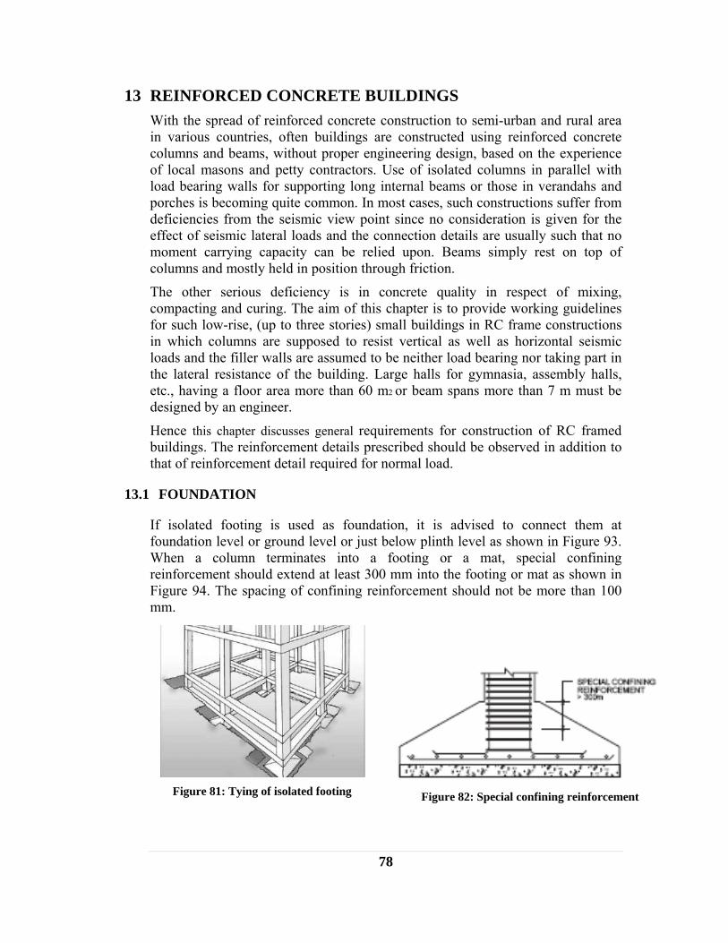
78
13 REINFORCED CONCRETE BUILDINGS With the spread of reinforced concrete construction to semi-urban and rural area in various countries, often buildings are constructed using reinforced concrete columns and beams, without proper engineering design, based on the experience of local masons and petty contractors. Use of isolated columns in parallel with load bearing walls for supporting long internal beams or those in verandahs and porches is becoming quite common. In most cases, such constructions suffer from deficiencies from the seismic view point since no consideration is given for the effect of seismic lateral loads and the connection details are usually such that no moment carrying capacity can be relied upon. Beams simply rest on top of columns and mostly held in position through friction.
The other serious deficiency is in concrete quality in respect of mixing, compacting and curing. The aim of this chapter is to provide working guidelines for such low-rise, (up to three stories) small buildings in RC frame constructions in which columns are supposed to resist vertical as well as horizontal seismic loads and the filler walls are assumed to be neither load bearing nor taking part in the lateral resistance of the building. Large halls for gymnasia, assembly halls, etc., having a floor area more than 60 m2 or beam spans more than 7 m must be designed by an engineer.
Hence this chapter discusses general requirements for construction of RC framed buildings. The reinforcement details prescribed should be observed in addition to that of reinforcement detail required for normal load.
13.1 FOUNDATION
If isolated footing is used as foundation, it is advised to connect them at foundation level or ground level or just below plinth level as shown in Figure 93. When a column terminates into a footing or a mat, special confining reinforcement should extend at least 300 mm into the footing or mat as shown in Figure 94. The spacing of confining reinforcement should not be more than 100 mm.
Figure 81: Tying of isolated footing
Figure 82: Special confining reinforcement
79
13.2 BEAM
13.2.1 Dimensions
• Beams should preferably have a width to depth ratio of more than 0.3.
• The width of the beam should not be less than 200 mm.
• The depth of the beam should preferably be not more than 1/4 of the clear span.
13.2.2 Longitudinal Reinforcement
• Top as well as bottom reinforcement should consist of at least two bars, of not less than 12 mm, throughout the member length.
• The tension steel in any face, at any section, should not be less than 0.3% (for concrete grade M15 or mix 1:2:4 and steel yield strength 415 MPa).
• The positive steel at a joint must be at least equal to half the negative steel at that section, subject to minimum of 0.2%.
• The maximum steel percentage on any face at any section should not exceed 2.5%.
• The steel provided at each of the top and bottom face of the member at any section along its length should at least equal to 1/4 of the maximum negative moment steel provided at the face of either joint.
• In an external joint, both the top and bottom bars of the beam should be provided with anchorage length, beyond the inner face of the column, equal to the development length in tension plus 10 times bar diameter minus allowance for 90 degree band (58xdiameter of bar for concrete grade M15 or mix 1:2:4) as shown in Figure 95.
• Splicing of bars by overlapping should be done using full development length (i.e. 56 x diameter of bar for concrete grade M15),
• Spliced length should be enclosed in stirrups spaced not more than 150 mm apart as shown in Figure 95.
• Not more than 50% of the bars should be spliced at any section. If the spacing between centers of splicing is more than 1.3 x lap length, staggered splicing should be considered.
• Splice position for bottom bars should be restricted to a region at least 2d (2x depth of beam) away from face of column but excluding the middle quarter length of effective span as shown in Figure 96.
• Top bars should be spliced in middle 1/3 of effective span as shown in Figure 96.
• All longitudinal bars of beam should pass through longitudinal bars of the column as shown in Figure 97.
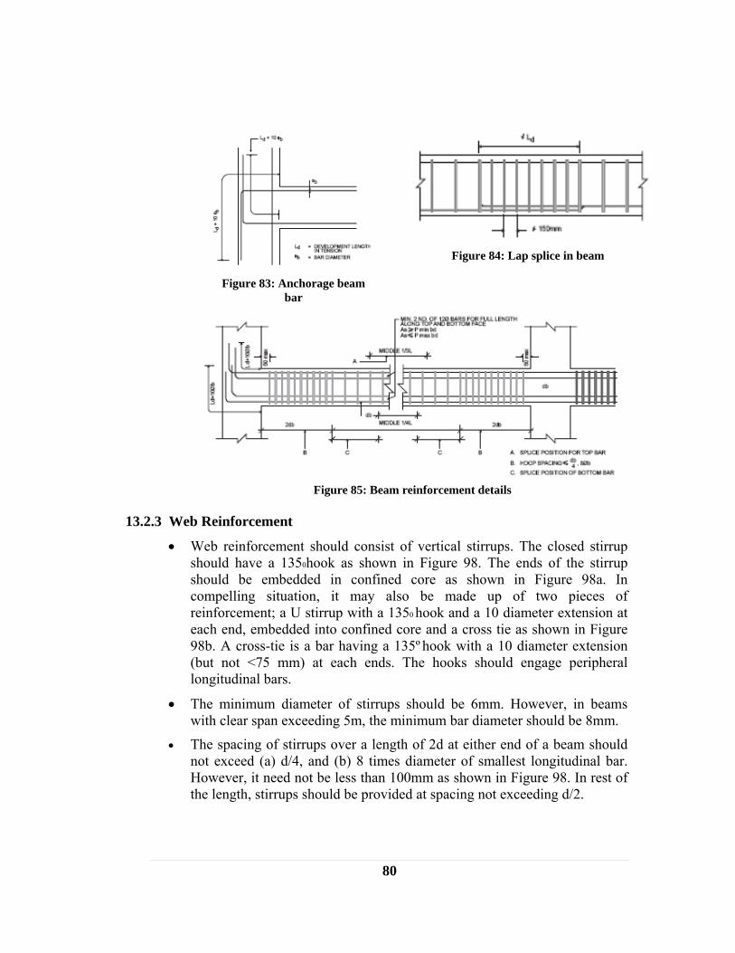
80
13.2.3 Web Reinforcement
• Web reinforcement should consist of vertical stirrups. The closed stirrup should have a 1350hook as shown in Figure 98. The ends of the stirrup should be embedded in confined core as shown in Figure 98a. In compelling situation, it may also be made up of two pieces of reinforcement; a U stirrup with a 1350 hook and a 10 diameter extension at each end, embedded into confined core and a cross tie as shown in Figure 98b. A cross-tie is a bar having a 135º hook with a 10 diameter extension (but not <75 mm) at each ends. The hooks should engage peripheral longitudinal bars.
• The minimum diameter of stirrups should be 6mm. However, in beams with clear span exceeding 5m, the minimum bar diameter should be 8mm.
• The spacing of stirrups over a length of 2d at either end of a beam should not exceed (a) d/4, and (b) 8 times diameter of smallest longitudinal bar. However, it need not be less than 100mm as shown in Figure 98. In rest of the length, stirrups should be provided at spacing not exceeding d/2.
Figure 83: Anchorage beam
bar
Figure 84: Lap splice in beam
Figure 85: Beam reinforcement details
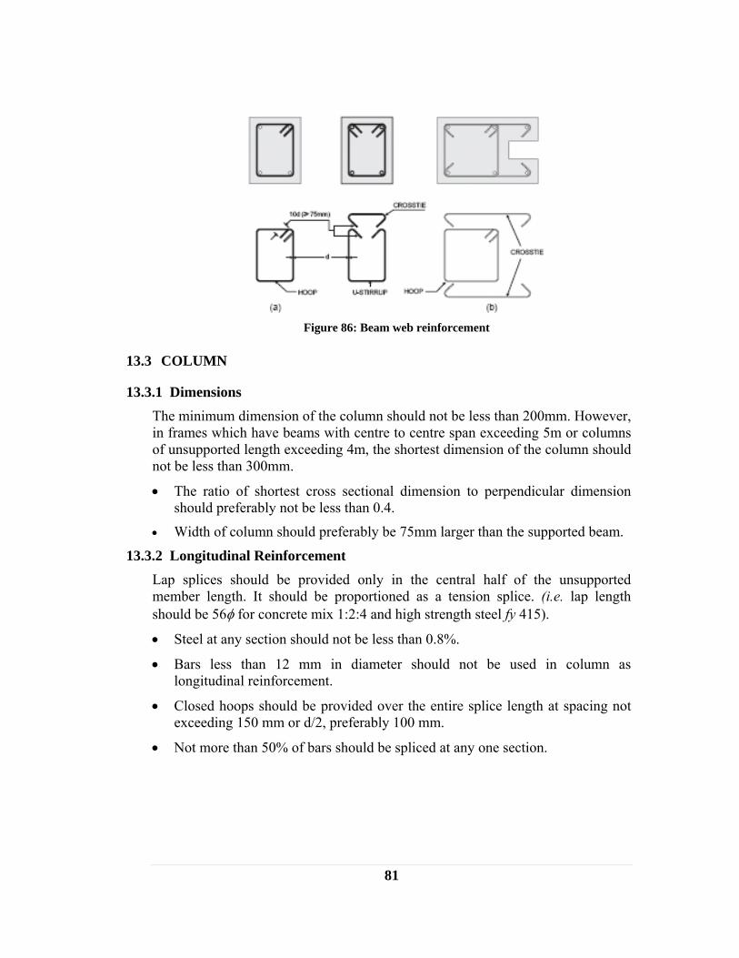
81
13.3 COLUMN
13.3.1 Dimensions The minimum dimension of the column should not be less than 200mm. However, in frames which have beams with centre to centre span exceeding 5m or columns of unsupported length exceeding 4m, the shortest dimension of the column should not be less than 300mm.
• The ratio of shortest cross sectional dimension to perpendicular dimension should preferably not be less than 0.4.
• Width of column should preferably be 75mm larger than the supported beam.
13.3.2 Longitudinal Reinforcement Lap splices should be provided only in the central half of the unsupported member length. It should be proportioned as a tension splice. (i.e. lap length should be 56φ for concrete mix 1:2:4 and high strength steel fy 415).
• Steel at any section should not be less than 0.8%.
• Bars less than 12 mm in diameter should not be used in column as longitudinal reinforcement.
• Closed hoops should be provided over the entire splice length at spacing not exceeding 150 mm or d/2, preferably 100 mm.
• Not more than 50% of bars should be spliced at any one section.
Figure 86: Beam web reinforcement
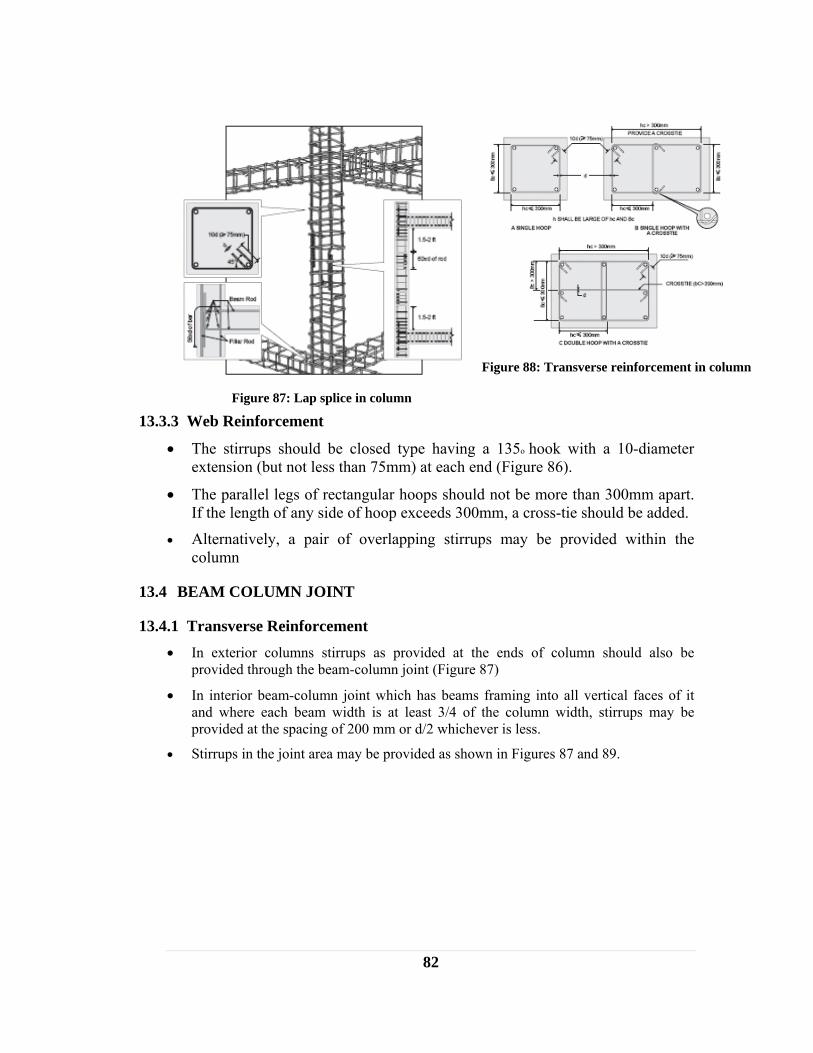
82
13.3.3 Web Reinforcement
• The stirrups should be closed type having a 135o hook with a 10-diameter extension (but not less than 75mm) at each end (Figure 86).
• The parallel legs of rectangular hoops should not be more than 300mm apart. If the length of any side of hoop exceeds 300mm, a cross-tie should be added.
• Alternatively, a pair of overlapping stirrups may be provided within the column
13.4 BEAM COLUMN JOINT
13.4.1 Transverse Reinforcement • In exterior columns stirrups as provided at the ends of column should also be
provided through the beam-column joint (Figure 87)
• In interior beam-column joint which has beams framing into all vertical faces of it and where each beam width is at least 3/4 of the column width, stirrups may be provided at the spacing of 200 mm or d/2 whichever is less.
• Stirrups in the joint area may be provided as shown in Figures 87 and 89.
Figure 87: Lap splice in column
Figure 88: Transverse reinforcement in column

83
13.5 RC SLAB
RC slab construction is good from seismic point of view as it helps to improve integrity of building. The following types of floor and roof are recommended:
• Cast-in-place RC floors or roofs: Two–way floor or roof slab are preferred to one way.
• Floor or roof made of precast elements must be well connected to the tie-beam (seismic band) reinforcement. RC topping screed having minimum thickness of 40mm should be provided. A reinforcing mesh of 4.75mm or 6mm diameter bars at the 200 mm interval in both the orthogonal directions has to be placed at the mid-depth of topping as shown in Figure 92. These bars should be well integrated with tie beam.
• Span of cantilever structural elements, such as balconies and overhangs should be limited to 1.2 m as shown in Figure 93.
Figure 89: Column and joint detailing
Figure 90: Hoop stirrups for joint
Figure 91: Stirrups for joint
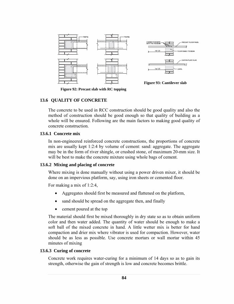
84
13.6 QUALITY OF CONCRETE
The concrete to be used in RCC construction should be good quality and also the method of construction should be good enough so that quality of building as a whole will be ensured. Following are the main factors to making good quality of concrete construction.
13.6.1 Concrete mix In non-engineered reinforced concrete constructions, the proportions of concrete mix are usually kept 1:2:4 by volume of cement: sand: aggregate. The aggregate may be in the form of river shingle, or crushed stone, of maximum 20-mm size. It will be best to make the concrete mixture using whole bags of cement.
13.6.2 Mixing and placing of concrete Where mixing is done manually without using a power driven mixer, it should be done on an impervious platform, say, using iron sheets or cemented floor.
For making a mix of 1:2:4,
• Aggregates should first be measured and flattened on the platform,
• sand should be spread on the aggregate then, and finally
• cement poured at the top
The material should first be mixed thoroughly in dry state so as to obtain uniform color and then water added. The quantity of water should be enough to make a soft ball of the mixed concrete in hand. A little wetter mix is better for hand compaction and drier mix where vibrator is used for compaction. However, water should be as less as possible. Use concrete mortars or wall mortar within 45 minutes of mixing
13.6.3 Curing of concrete Concrete work requires water-curing for a minimum of 14 days so as to gain its strength, otherwise the gain of strength is low and concrete becomes brittle.
Figure 92: Precast slab with RC topping
Figure 93: Cantilever slab
85
Concrete slabs may be kept under water by ponding of water over it by making earthen barriers around the edges.
Columns should be kept covered with wet empty gunny bags. Keeping the side forms intact on the beam webs will prevent the evaporation of water from the concrete and help in curing.
Covering any concrete surface with polyethylene sheets after wetting the surface will help retain the moisture.
13.6.4 Construction joints Where a joint is to be made, the surface of the concrete should be thoroughly cleaned and all laitance removed. The surface should be thoroughly wetted, and covered with a coat of neat cement slurry immediately before placing of new concrete. Construction joints in floors should be located near the middle of the spans of slabs, beams or girders, unless a beam intersects a girder at this point, in which case the joints in the girders should be offset a distance equal to twice the width of the beam. Provision of keys should be made for transfer of shear through the construction joint.

86
14 REPAIR AND STRENGTHENING OF EXISTING BUILDINGS The retrofitting is the actions taken to upgrade the seismic resistance of an existing building so that it becomes safer under future earthquakes.
This can be in the form of providing seismic bands, eliminating sources of weakness or concentrations of large mass and openings in walls, adding shear walls or strong column points in walls, bracing roofs and floors to be able to act as horizontal diaphragms, adequately connecting roofs to walls and columns and also connecting between walls and foundations.
14.1 ASSESSMENT OF BUILDING DAMAGE
The assessment of building damage must be done before carrying out repairs or strengthening
Before commencing any repairs it is important to
• Determine the materials which have been used in the damaged building
• Carry out a detailed foundation check;
• Carry out a detailed structural assessment of the damaged building with particular attention to vulnerable elements of the structure.
This should be assessed by a qualified structural engineer. It should be noted that both nonstructural and structural repairs might be required to a building. The priority repairs should be to the structural components before embarking on any non- structural repairs (cracked slabs, falling plaster from walls and ceilings, rebuilding of parapets etc).
There is absolutely no point carrying out repairs to a building if the foundations have failed or the ground can no longer support the damaged building. Repairs to damaged foundations can be costly and difficult to instigate and hence a fine line may exist between demolishing the building or continuing with the repair.
Moreover, the site can become dangerous. In fact, earthquakes may cause failure of soft or loose ground whilst hillsides or sloping ground may become unstable. Whole towns and villages may be affected and although a building may appear safe for repair, near the foot of the slope or on it, further slope failures could be triggered by relatively small aftershocks or another future earthquake. Buildings in such terrain will require specialist advice of the stability of the whole area. No repairs to buildings should take place until this advice has been obtained
14.2 REPAIR AND STRENGTHENING
14.2.1 Foundations One of the most frequent causes of deterioration of the walls of a house is their direct contact with the ground humid thus making them vulnerable in the event of an earthquake.

87
Example: ground sloping towards the wall, unstable and poor quality foundations and wall bases, prone to settling due to the effect of humidity and the inferior quality of the ground.
A. Alternative 1: Cleaning & Drainage
If after an earthquake the wall has cracks in certain sections and the adobe bricks are in a satisfactory state we must eliminate the earth which covers the wall base, and level out the ground a minimum of 10cm below the wall base.
B. Alternative 2: Demolition & Reconstruction
If after an earthquake the base of the wall has become loose, if there are cracks in the entire wall and sinking which make the wall unstable and dangerous we must then: Dismantle it after propping it up and build a new wall from the foundations.
Figure 94: Defects in foundation
Figure 95: Cleaning and drainage of
foundation

88
14.2.2 Walls After an earthquake, if a wall has become out of plumb by more than 2% per meter, then it will need to be dismantled or completely demolished since this deformation makes the wall lose its carrying capacity. To do this you will need to dismantle the wall after having checked the stability of the roof as described above.
If the out of plumb is less than 1% and the walls do not show any signs of damage or diagonal cracks which cross it completely, the affected parts can be repaired.
Figure 96: Demolition and reconstruction of
foundation
Figure 97: Deflection of existing walls
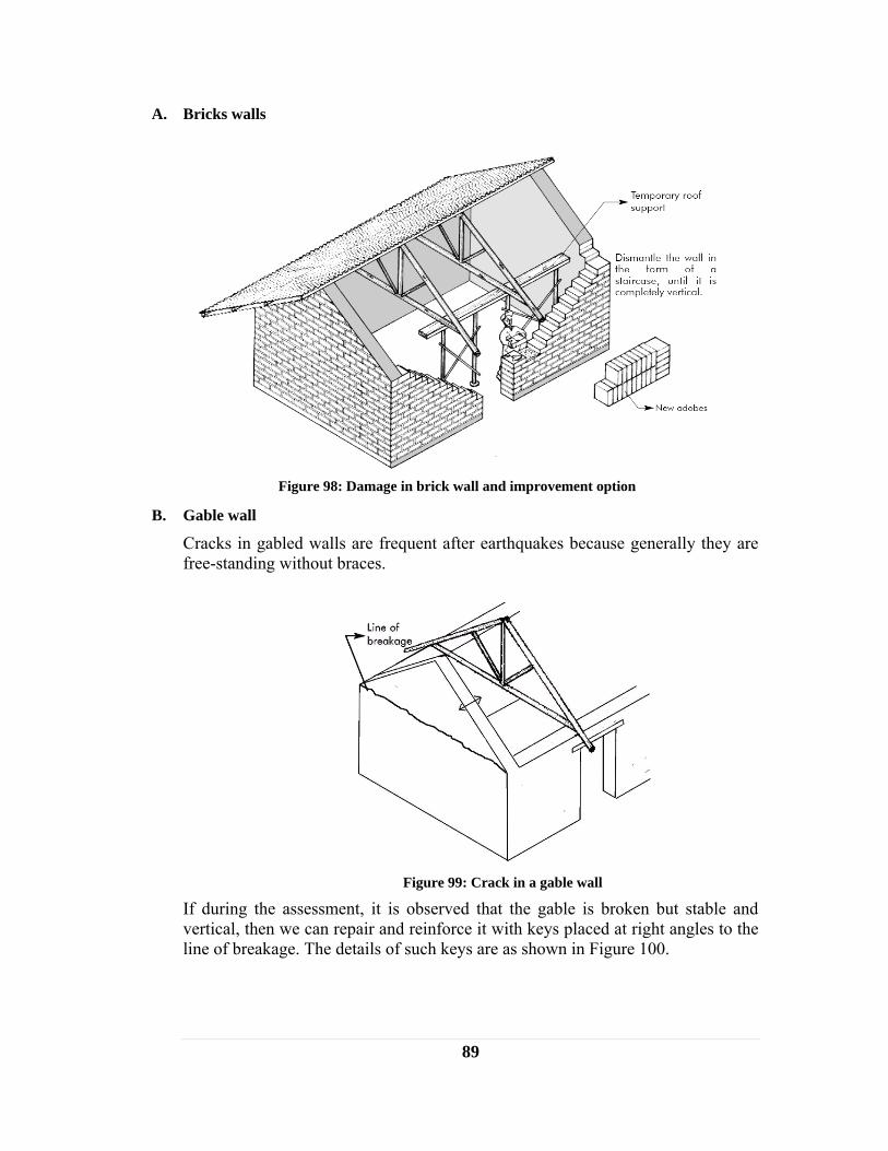
89
A. Bricks walls
B. Gable wall
Cracks in gabled walls are frequent after earthquakes because generally they are free-standing without braces.
If during the assessment, it is observed that the gable is broken but stable and vertical, then we can repair and reinforce it with keys placed at right angles to the line of breakage. The details of such keys are as shown in Figure 100.
Figure 98: Damage in brick wall and improvement option
Figure 99: Crack in a gable wall
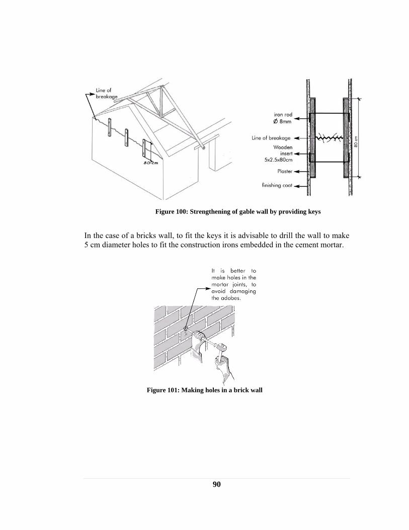
90
In the case of a bricks wall, to fit the keys it is advisable to drill the wall to make 5 cm diameter holes to fit the construction irons embedded in the cement mortar.
Figure 100: Strengthening of gable wall by providing keys
Figure 101: Making holes in a brick wall

91
Lightened Gable If the earthquake has caused serious damage in the gabled wall and part of it has collapsed, then it is advisable to dismantle it and change it for a frame or a weatherboard which will be much lighter and more resistant in the event of an earthquake.
Using the "wattle and daub" technique consists of making a frame with cane, poles or made from a similar material, covered with clay mortar.
Figure 102 shows in detail the solution with cane or poles tied with galvanized wire and covered with earth mortar.
Figure 102: Making gable wall lighter using wattle and daub technique
C. Wall corner
Reinforcement with keys
Corner joints tend to be weak areas in the event of an earthquake, especially when they do not have correct bonding.
If the cracks are not serious and there is no loosening, then they can be repaired by fitting keys. It is advisable to fit them at 5 row intervals taking advantage of the mortar joints. Take great care when cutting the wall to fit the wooden parts
Figure 103: Cracks at corner

92
which make up the key so as to cause as little damage as possible to the adobe. Afterwards cover any remaining spaces between the key and the wall with clay and straw mortar.
Figure 104: Corner strengthening with key
Dismantling and Reconstruction When the walls have suffered greater damage, like collapsed sections, a more delicate operation is needed. First dismantle the wall in the form of a "staircase" on both sides, and then rebuild the wall with new bricks or stones. In order to avoid this happening again, fit supports at 4 row intervals (keys), these will be embedded in the wall. Another possibility is to rebuild with buttresses, in which case you will need to start from the foundations.
Figure 105: Dismantling damaged portion and reconstructing new wall

93
The figure below shows an alternative option to insert "keys". This solution uses wooden sticks or canes, and is equally efficient, in the event of an earthquake. Other materials and techniques can also be used: wood, bamboo or wire mesh with concrete.
14.2.3 Roof After an earthquake, there may be cracks in the part which supports the load of the roof, mainly when the ring beam which distributes the load horizontally is missing. In such case, the cracked portion of wall can be replaced.
For this first of all, the roof structure above needs to be supported at the place where the replacement is being. Once the roof has been supported, the damaged adobes are eliminated and replaced. The topmost layer of the wall is removed and replaced with a ring beam or a wall plate (made from wood, cement, bamboo or a similar material). Afterwards the roof structure will return to its initial position.
There are two ways of fitting a ring beam:
Figure 106: Corner strengthening with key
Figure 107: Cracks at the bottom of roof support
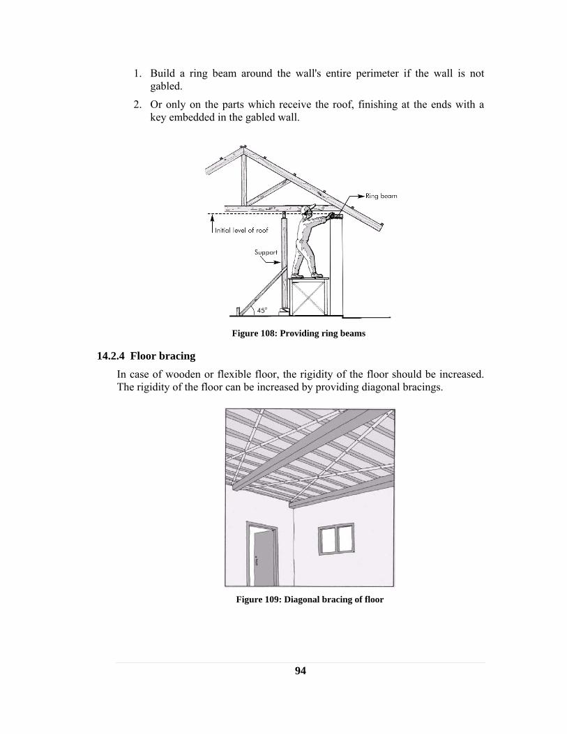
94
1. Build a ring beam around the wall's entire perimeter if the wall is not gabled.
2. Or only on the parts which receive the roof, finishing at the ends with a key embedded in the gabled wall.
14.2.4 Floor bracing In case of wooden or flexible floor, the rigidity of the floor should be increased. The rigidity of the floor can be increased by providing diagonal bracings.
Figure 108: Providing ring beams
Figure 109: Diagonal bracing of floor

95
REFERENCES 1. ADPC; Regional Workshop on Best Practices in Disaster Mitigation, Indonesia,
September 2002. 2. AKPBSP, BACIP; “Galvanized Wire-Mesh Wall Reinforcement Methodology”,
“The Development of the Wire-Mesh Knotting Equipment”, “BACIP Galvanized Wire-Mesh Wall Reinforcement”, “Development of the BACIP Wire-Mesh Knotting Equipment”, “BACIP, Insulation advice table”, Aga Khan Planning and Building Services, Pakistan (AKPBSP), Pakistan.
3. Arya, A. S. et al; Guidelines for Earthquake Resistant Non-Engineered Construction, International Association for Earthquake Engineering, 1986.
4. Arya, A. S.; Protection of Educational Buildings against Earthquakes, Education Building Report #13, UNESCO Principal Regional Office for Asia and the Pacific, Bangkok, Thailand, 1987.
5. Arya; Earthquake-Resistant Reconstruction and New Construction of Masonry Building in Jammu and Kashmir State, Prof. Anand S. Arya, National seismic Advisor, 2005
6. Coburn, A. and Spence, R.; Earthquake Protection, John Wiley and Sons. 7. CRA Terre; Anti-seismic Construction Handbook. 8. EERI; Annotated Slide Set: A visual presentation of EERI Slide Sets on CD,
Earthquake Engineering Research Institute (EERI). 9. IITK-BMTPC Earthquake Tip Series (www.nicee.org), Indian Institute of
Technology, Kanpur and Building Materials and Technology Promotion Council, New Delhi, India.
10. IS 13920-1993; Ductile Detailing of Reinforced Concrete Structures Subjected to Seismic Forces – Code of Practice, Bureau of Indian Standards, New Delhi, India.
11. IS 1893-1984, Criteria for Earthquake Resistant Design of Buildings and Structures, Bureau of Indian Standards, New Delhi, India.
12. IS 4326-1993; Earthquake Resistant Design and Construction of Buildings – Code of Practice, Bureau of Indian Standards, New Delhi, India.
13. NBC 108-1994; Site Consideration, Government of Nepal, Ministry of Housing and Physical Planning, Department of Buildings, Nepal, 1995.
14. NBC 109-1994; Masonry: Unreinforced, Government of Nepal, Ministry of Housing and Physical Planning, Department of Buildings, Nepal, 1995.
15. NBC 201-1994; Mandatory Rules of Thumb: Reinforced Concrete Buildings with Masonry Infill, Government of Nepal, Ministry of Housing and Physical Planning, Department of Buildings, Nepal, 1995.
16. NBC 202-1994; Mandatory Rules of Thumb Reinforced Concrete Buildings without Masonry Infill, Government of Nepal, Ministry of Housing and Physical Planning, Department of Buildings, Nepal, 1995.
17. NBC 202-1994; Mandatory Rules of Thumb: Load Bearing Masonry, Government of Nepal, Ministry of Housing and Physical Planning, Department of Buildings, Nepal, 1995.

96
18. NBC 203-1994; Guidelines for Earthquake Resistant Building Construction: Low Strength Masonry, Government of Nepal, Ministry of Housing and Physical Planning, Department of Buildings, Nepal, 1995.
19. NBC 204-1994; Guidelines for Earthquake Resistant Building Construction: Earthen Buildings (EB), Government of Nepal, Ministry of Housing and Physical Planning, Department of Buildings, Nepal, 1995.
20. NSET; Earthquake Resistant Construction of Buildings Curriculum for Mason Training – Guidelines for Training Instructors, National Society for Earthquake Technology - Nepal; Asian Disaster Preparedness Centre, Kathmandu, February 2005.
21. NSET; Protection of Educational Buildings against Earthquakes: A Manual for Designers and Builders, National Society for Earthquake Technology – Nepal (NSET), Kathmandu, 2000.
22. The website of Earthquake Engineering Research Institute (EERI): www.eeri.org 23. The website of National Earthquake Information Center: www.neic.gov 24. The website of National Information Center for Earthquake Engineering
(NICEE): www.nicee.org 25. The website of United States Geological Survey (USGS): www.usgs.gov 26. UNCRD; Guidelines for Earthquake Resistant Design, Construction, and
Retrofitting of Buildings in Afghanistan, Ministry of Urban Development and Housing (MUDH), United Nations Centre for Regional Development (UNCRD), Afghanistan, June 2003.
27. UN-HABITAT; Guidelines for Earthquake Resistant Construction of Non-Engineered Rural and Suburban Houses in Afghanistan, Kabul, July, 2005
28. World of Natural Hazards, Munich Re Group, 2001.