guideline for control surveys by gnss special … · gnss surveying involves the collection of...
TRANSCRIPT

Guideline for Control Surveys
by GNSS
Special Publication 1
Version 2.1
Intergovernmental Committee on Surveying and Mapping (ICSM)
Permanent Committee on Geodesy (PCG)
24 September 2014
Intergovernmental Committee on Surveying and Mapping
Guideline for Control Surveys by GNSS – SP1 ii Version 2.1
Document History
DATE VERS ISSUE AMENDMENTS AUTHOR(S)
24/10/2013 2 0 Document available ICSM Permanent Committee on Geodesy
24/09/2014 2 1 Inclusion of real-time GNSS surveys, copyright updated
ICSM Permanent Committee on Geodesy
© Commonwealth of Australia (ICSM) 2014
With the exception of the ICSM logo and where otherwise noted, all material in this publication is provided under a Creative Commons Attribution 3.0 Australia Licence (http://www.creativecommons.org/licenses/by/3.0/au/)

Intergovernmental Committee on Surveying and Mapping
Guideline for Control Surveys by GNSS – SP1 iii Version 2.1
Table of contents
Document History .......................................................................................................... ii
Table of contents .......................................................................................................... iii
List of tables ................................................................................................................. iv
List of figures ................................................................................................................ iv
Terms and definitions .................................................................................................... v
1 About this Guideline ................................................................................................ 1
1.1 Introduction ............................................................................................................ 1
1.2 Normative References ............................................................................................ 2
2 Connection to datum ............................................................................................... 3
2.1 Datum transformations .......................................................................................... 3
2.2 AHD height transformations................................................................................... 3
3 GNSS survey guidelines ............................................................................................ 5
3.1 General considerations ........................................................................................... 5
3.1.1 Static surveys .................................................................................................... 6
3.1.2 Real-time surveys ............................................................................................. 7
3.2 GNSS equipment and observation techniques ....................................................... 7
3.2.1 Static surveys .................................................................................................... 7
3.2.2 Real-time surveys ............................................................................................. 8
3.3 GNSS processing procedures ................................................................................ 10
3.3.1 Static surveys .................................................................................................. 10
3.3.2 Real-time surveys ........................................................................................... 10
4 Uncertainty of GNSS surveys .................................................................................. 11
4.1 Classifying AHD heights derived from GNSS and AUSGeoid ................................ 11
5 Evaluation of real-time GNSS surveys using coordinate comparison ........................ 12
6 AUSPOS online GPS processing service ................................................................... 16
Intergovernmental Committee on Surveying and Mapping
Guideline for Control Surveys by GNSS – SP1 iv Version 2.1
List of tables
Table 1: GNSS observation techniques for Classic Static and Quick Static surveys to achieve nominated levels of survey uncertainty .................................................................................. 7
Table 2: GNSS equipment and observation techniques for real-time surveys ........................ 8
Table 3: Minimum GNSS processing software recommendations for Classic Static and Quick Static surveys ......................................................................................................................... 10
List of figures
Figure 1: Relationship between the ellipsoid, geoid, AHD and the topography ..................... 4
Figure 2: GNSS survey techniques ........................................................................................... 5
Figure 3: Example network of marks to be coordinated ....................................................... 13
Intergovernmental Committee on Surveying and Mapping
Guideline for Control Surveys by GNSS – SP1 v Version 2.1
Terms and definitions
For the purpose of this Guideline, the terms and definitions listed below and those listed in the Standard for the Australian Survey Control Network – Special Publication 1, Version 2.1 apply.
Term/Acronym Definition
Elevation mask
A GNSS receiver setting that determines whether GNSS signals are recorded below a certain angle above the horizon.
IGS International GNSS Service - An international federation of agencies that pool resources to operate a global CORS network whose data is used, amongst other purposes, to generate precise GNSS products in support of Earth science research.
Multipath Errors in GNSS observations caused by reflected GNSS signals interfering with the direct GNSS signal due to their common time origin but different path lengths.
Network Real-time Kinematic (NRTK)
A technique which produces real-time corrections from a network of CORS, to reduce the uncertainty in the position of the rover.
NGS National Geodetic Survey – United States of America national mapping agency.
Real-time Kinematic (RTK) A technique which uses real-time corrections from reference stations, either as a temporary setup or as a CORS, to reduce the uncertainty in the position of the rover.
Redundancy A least squares solution is said to contain redundancy if the total number of measurements exceeds the minimum number required to compute the unknown parameters.
RINEX Receiver INdependent EXchange – An internationally accepted format for the exchange of GNSS data between software applications and for GNSS data archiving.

Intergovernmental Committee on Surveying and Mapping
Guideline for Control Surveys by GNSS – SP1 1 Version 2.1
1 About this Guideline
1.1 Introduction
The availability of accurate and reliable information relating to the position and uncertainty of Australia’s survey control marks is critical to the integrity of the National Geospatial Reference System (NGRS). The purpose of this Guideline is to promote the adoption of uniform Global Navigation Satellite System (GNSS) surveying procedures to achieve the highest level of rigour and integrity in Australia’s survey control mark network.
GNSS surveying involves the collection of precise code and carrier phase measurements recorded simultaneously at two or more survey control marks using high precision GNSS equipment and/or Continuously Operating Reference Stations (CORS). Those measurements can then be processed to derive GNSS baselines from which the 3D position and uncertainty for each survey control mark can be estimated. The processing of the GNSS measurements can be done in real-time in the field or after completion of the field measurements in so-called post-processing.
GNSS based surveys can vary in quality, depending on the type of GNSS receiver, antenna, ancillary equipment and observation parameters chosen. All have a direct influence on the uncertainty of derived GNSS measurements. Similarly, variation in measurement uncertainty will result from the spatial extent of the survey, the presence of certain external influences and the environmental conditions under which the control survey is undertaken. The uncertainty of derived coordinates is directly related to the technique chosen for a GNSS survey.
There may also be additional measurement and processing techniques not covered in this Guideline that may be judged by a surveyor to be suitable for particular types of General Purpose Control Surveys. However, those additional techniques including Precise Point Positioning (PPP), code-based Differential GNSS and Single Point Positioning are not suitable for Datum Control Surveys and are beyond the scope of this Guideline.
It is recognised that with the current momentum of development in GNSS technology, GNSS equipment, software and processing algorithms will continue to improve and as such this Guideline will face ongoing revision.
This Guideline outlines ICSM’s recommended equipment and procedures for GNSS surveying.
Intergovernmental Committee on Surveying and Mapping
Guideline for Control Surveys by GNSS – SP1 2 Version 2.1
1.2 Normative References
This Guideline should be read in conjunction with the Standard for the Australian Survey Control Network – Special Publication 1, Version 2.1 herein referred to as the Standard.
The following documents may have relevance to the application of this Guideline.
International Guidelines
JCGM 100:2008, Evaluation of Measurement Data – Guide to the Expression of Uncertainty in Measurement, Joint Committee for Guides in Metrology – Bureau International des Poids et Mesures, Paris, France.
SP1 Standard
ICSM (2014), Standard for the Australian Survey Control Network – Special Publication 1, Version 2.1, Intergovernmental Committee on Surveying and Mapping, Canberra, Australia.
SP1 Guidelines
ICSM (2014), Guideline for the Adjustment and Evaluation of Survey Control, Version 2.1, Intergovernmental Committee on Surveying and Mapping, Canberra, Australia.
ICSM (2014), Guideline for Control Surveys by Differential Levelling, Version 2.1, Intergovernmental Committee on Surveying and Mapping, Canberra, Australia.
ICSM (2014), Guideline for the Installation and Documentation of Survey Control Marks, Version 2.1, Intergovernmental Committee on Surveying and Mapping, Canberra, Australia.
ICSM (2014), Guideline for Continuously Operating Reference Stations, Version 2.1, Intergovernmental Committee on Surveying and Mapping, Canberra, Australia.
ICSM Technical Manuals
ICSM (2006), Geocentric Datum of Australia Technical Manual, Intergovernmental Committee on Surveying and Mapping, Canberra, Australia.
ICSM (2007), Australian Tides Manual – Special Publication 9, Intergovernmental Committee on Surveying and Mapping, Wollongong, Australia.
Technical Publications
Dawson, J. and Woods, A. (2010), ITRF to GDA94 coordinate transformations, Journal of Applied Geodesy, 4:4, pp. 189–199.
Brown, N. J., Featherstone, W. E., Hu, G. and Johnston, G. (2011), AUSGeoid09: A more direct and more accurate model for converting ellipsoidal heights to AHD heights, Journal of Spatial Science, 56:1, pp. 27–37.

Intergovernmental Committee on Surveying and Mapping
Guideline for Control Surveys by GNSS – SP1 3 Version 2.1
2 Connection to datum
Survey control marks established for Australia’s NGRS shall be coordinated relative to the datums set out in Section 2 of the Standard.
2.1 Datum transformations
As outlined in the Standard, GDA94 is a static coordinate datum based on the International Terrestrial Reference Frame (ITRF) 1992, held fixed at the reference epoch of 1 January 1994.
Users typically access GNSS reference frames by processing their GNSS measurements relative to:
the Broadcast Ephemerides of the relevant GNSS; or
a suitable IGS Precise Ephemerides product.
In the case of Broadcast Ephemerides, the official reference frames for all GNSS are closely aligned to a version of ITRF. However, there may be differences between the ITRF realisation and reference epoch used for a given GNSS compared to those used for GDA94. By 2010, for example, the horizontal difference between GDA94 and WGS84 (as used for the GPS Broadcast Ephemerides) had exceeded one metre.
In the case of Precise Ephemerides, IGS uses the most modern ITRF realisation and the current week for the reference epoch. This can also introduce significant differences compared to GDA94.
Due to these reference frame differences, appropriate datum transformations should be applied during the processing of GNSS survey measurements and the estimation of survey control mark coordinates in order to produce coordinates consistent with GDA94. For this purpose, ICSM recommends the use of the ITRF-GDA94 transformation parameters published by Dawson and Woods (2010).
2.2 AHD height transformations
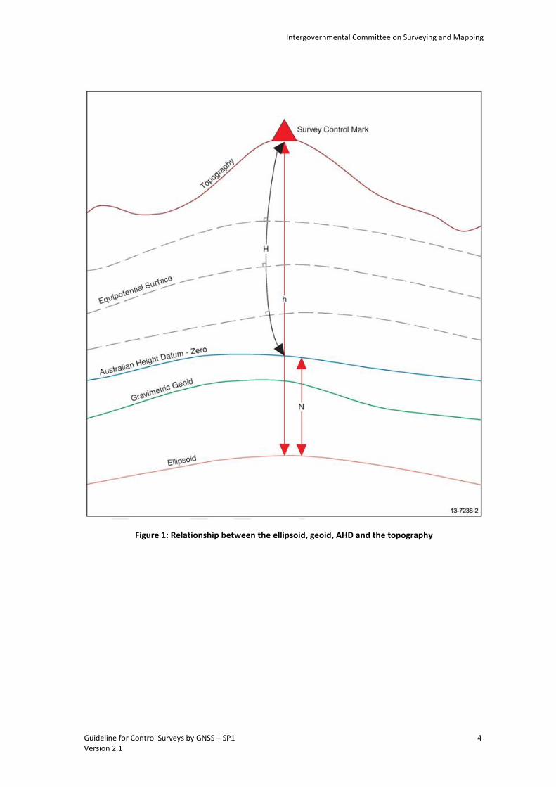
As outlined in the Standard, the height datum for Australia is the Australian Height Datum (AHD). Since measurements and coordinates derived from GNSS are based on a reference ellipsoid (a purely mathematical surface), heights obtained using GNSS surveying will not be aligned to the geoid, AHD or any other gravity-based height datum. Figure 1 shows the typical relationship between the ellipsoid, geoid, AHD and the topography.
GNSS-derived ellipsoidal heights can be transformed using AUSGeoid (see Section 4.1) to account for the misalignment between AHD and the reference ellipsoid. As indicated by Figure 1, “derived AHD heights” (H) can be computed from GNSS ellipsoidal heights (h) using reliable AHD–ellipsoid separation values (known as N values). Conversely, N values can be used to compute “derived ellipsoidal heights” from AHD heights.
Intergovernmental Committee on Surveying and Mapping
Guideline for Control Surveys by GNSS – SP1 4 Version 2.1
Figure 1: Relationship between the ellipsoid, geoid, AHD and the topography
Intergovernmental Committee on Surveying and Mapping
Guideline for Control Surveys by GNSS – SP1 5 Version 2.1
3 GNSS survey guidelines
3.1 General considerations
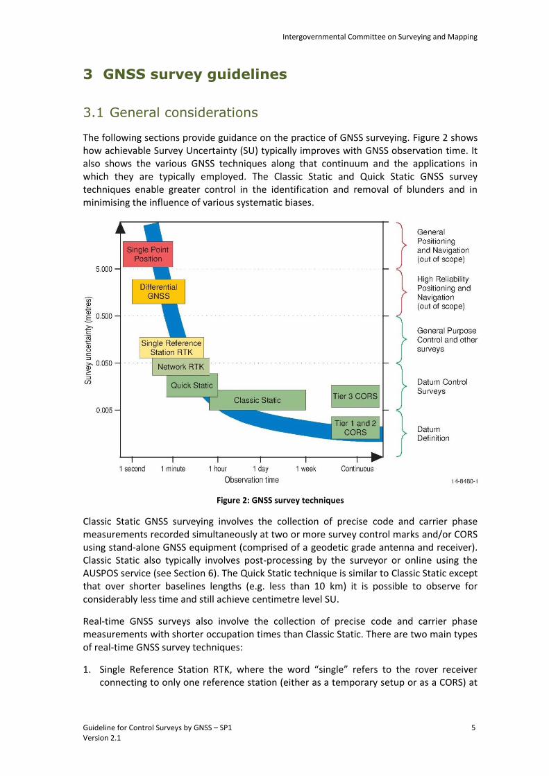
The following sections provide guidance on the practice of GNSS surveying. Figure 2 shows how achievable Survey Uncertainty (SU) typically improves with GNSS observation time. It also shows the various GNSS techniques along that continuum and the applications in which they are typically employed. The Classic Static and Quick Static GNSS survey techniques enable greater control in the identification and removal of blunders and in minimising the influence of various systematic biases.
Figure 2: GNSS survey techniques
Classic Static GNSS surveying involves the collection of precise code and carrier phase measurements recorded simultaneously at two or more survey control marks and/or CORS using stand-alone GNSS equipment (comprised of a geodetic grade antenna and receiver). Classic Static also typically involves post-processing by the surveyor or online using the AUSPOS service (see Section 6). The Quick Static technique is similar to Classic Static except that over shorter baselines lengths (e.g. less than 10 km) it is possible to observe for considerably less time and still achieve centimetre level SU.
Real-time GNSS surveys also involve the collection of precise code and carrier phase measurements with shorter occupation times than Classic Static. There are two main types of real-time GNSS survey techniques:
1. Single Reference Station RTK, where the word “single” refers to the rover receiver connecting to only one reference station (either as a temporary setup or as a CORS) at

Intergovernmental Committee on Surveying and Mapping
Guideline for Control Surveys by GNSS – SP1 6 Version 2.1
any given time, even though more than one reference station may be used at different times across the project; and
2. Network RTK surveys using a network of CORS.
The location and distribution of survey control marks in a GNSS survey do not depend significantly on factors such as network shape or mark inter-visibility, but rather on an optimum layout with sufficient redundancy to achieve the intent of the survey and any required specifications.
Site selection and planning of observation sessions should aim to minimise the influence of internal and external effects. Factors that typically influence GNSS measurements include:
GNSS system effects such as ephemeris error and satellite availability and geometry at each survey site;
atmospheric effects due to the ionosphere and troposphere;
site-dependent effects such as obstructions, multipath and interference from non-GNSS radio sources; and
instrumental effects, most noticeably un-modelled antenna phase centre offsets.
Redundancy in the observations, absence of signal obstructions and longer observation times are well-accepted methods for minimising the errors due to these effects.
The final estimation of survey mark positions is also influenced by effects external to the GNSS measurements themselves, and surveyors should incorporate procedures for minimising blunders by checking mark identifiers, the centring and orientation of the antenna and the measurement of antenna heights.
3.1.1 Static surveys
Given the three-dimensional nature of modern surveys, surveyors should be aware that achieving centimetre or millimetre level SU in ellipsoidal height requires significantly more attention than for horizontal position. The influence of GNSS observation time is particularly important for height. Longer observation times influence the achievable uncertainty of ellipsoidal heights by minimising the effects of the atmosphere (especially troposphere in the case of heights) as well as satellite geometry and antenna models.
Given that the desired uncertainty for ellipsoidal height dominates the selection of equipment, observation and processing techniques, the following sections are based on achieving SU in ellipsoidal height in two categories, namely “better than 20 mm” and “better than 50 mm”. A general rule of thumb is that GNSS surveying achieves SU in ellipsoidal height that is approximately 1.5 to 2.0 times worse than for horizontal position. Therefore in using the recommended procedures in the following sections, it should be possible to achieve SU for horizontal position that can be categorised as “better than 15 mm” and “better than 30 mm”.
It should be noted that individual government departments may have additional requirements for GNSS control surveys and may issue supplementary advice.

Intergovernmental Committee on Surveying and Mapping
Guideline for Control Surveys by GNSS – SP1 7 Version 2.1
3.1.2 Real-time surveys
It should be noted that real-time GNSS techniques are generally considered suitable for General Purpose Control Surveys only. The use of real-time GNSS techniques for Datum Control Surveys may be accepted by some NGRS authorities when the baselines, variances and covariances generated from the real-time processing are available for inclusion in the NGRS adjustment.
3.2 GNSS equipment and observation techniques
3.2.1 Static surveys
GNSS equipment and observation techniques employed have a direct impact on the uncertainty of the survey results. Table 1 lists the recommended GNSS observation techniques for Classic Static and Quick Static surveys to achieve nominated levels of SU.
Table 1: GNSS observation techniques for Classic Static and Quick Static surveys to achieve nominated levels of survey uncertainty
SU < 15 mm for horizontal position SU < 20 mm for ellipsoidal height
SU < 30 mm for horizontal position SU < 50 mm for ellipsoidal height
Technique:
Classic Static Classic Static, Quick Static acceptable for baselines less than 10 km
Receiver:
Capable of dual frequency code and carrier phase tracking
Antenna:
Choke ring or ground-plane Survey quality
High quality tripod, tribrach and optical plummet
Session length:
6 to 24 hours depending on baseline length
Classic Static: 1 to 6 hours depending on baseline length. Recommend 1 hour plus five
minutes per 1km
Quick-Static: manufacturer recommendations for ambiguity resolution given baseline length
and number of satellites
Observation epoch interval maximum:
30 seconds Classic Static: 15 to 30 seconds Quick-Static: 5 to 15 seconds
Other:
Independent occupations recommended (with 30 minute gap and reset of antenna if on tripod)
Elevation mask set to record down to zero degrees elevation

Intergovernmental Committee on Surveying and Mapping
Guideline for Control Surveys by GNSS – SP1 8 Version 2.1
Antenna orientated to within 5 degrees of true North
Datum connection to at least two survey control marks being either marks in the existing Datum Control Survey Adjustment or Regulation 13 Certified CORS
All GNSS and ancillary equipment should be maintained and regularly checked for accuracy and be in sound working order. Testing of receiver and antenna after firmware upgrade is also recommended.
3.2.2 Real-time surveys
Given that marks are typically only occupied for a short time during real-time surveys, site selection and survey planning should pay special attention to minimising site dependent effects such as multipath, interference and obstructions. Other influences that should also be minimised include GNSS system effects, atmospheric effects and instrumental effects.
Selection of suitable communications equipment is also crucial in real-time GNSS surveying. Dedicated radios or an internet connection via mobile phone may be used. Therefore, radio range, radio licensing and/or mobile phone coverage are also important considerations.
Table 2 lists the recommended GNSS observation techniques for single reference station RTK and network RTK to achieve nominal horizontal and vertical SU levels. Note that the SU levels nominated in the following tables are indicative of the upper limits of SU typical with real-time GNSS Surveys. The actual SU achieved will be dependent on the specifications of the receivers and antennas used and on the distance between the rover and reference station(s). It should also be noted that the propagation of uncertainty is different between Single Reference Station RTK and Network RTK.
Table 2: GNSS equipment and observation techniques for real-time surveys
SU < 40 mm for horizontal position SU < 60 mm for ellipsoidal height
Technique:
Single Reference Station RTK Network RTK
Receiver:
Dual frequency code and carrier phase tracking
Antenna:
Survey quality antenna for rover and reference station(s)
Fixed height pole and bipod for rover
Reference station establishment:

Intergovernmental Committee on Surveying and Mapping
Guideline for Control Surveys by GNSS – SP1 9 Version 2.1
Tripod, tribrach and optical plummet setup over a survey control mark.
Where multiple reference stations are used, the internal consistency of the RTK survey relies on minimising RU between the reference stations:
Use existing coordinated marks, e.g. part of Datum Control Survey adjustment; or
For new marks, undertake a Static or Quick Static GNSS survey between the reference station marks and connect to Datum (see below).
If required, refer to the SP1 Guideline for Continuously Operating Reference Stations.
Connection to datum:
Connect the reference station survey to at least two survey control marks in the existing Datum Control Survey adjustment or, in remote areas, process reference station data through AUSPOS.
Check on existing control to verify that datum and other settings in reference station and rover are correct.
Using a different reference station location for the second rover occupation can help isolate any problems with reference station data.
Use of a service based on Regulation 13 Certified CORS is highly recommended, otherwise check datum of the RTK Network by occupying marks in the Datum Control Survey adjustment.
Connection to AHD:
Where AHD is required on new marks, it is recommended to occupy at least two existing AHD marks to check AUSGeoid fit in the project area.
Rover range:
Distance between reference station and rover should typically be less than 20 km.
Rover should only work within the Network RTK coverage area recommended by the
service provider.
Checking rover occupations:
All rover marks occupied twice, ideally with 30 minutes between occupations.
Rover session length:
Record and average positions for at least 1 minute after the rover has successfully initialised (i.e. after ambiguity resolution).
Observation epoch interval at reference station and rover:
1 second logging of the raw GNSS data is recommended to enable post-processing if checks are required at a later date.
Elevation mask at reference station and rover:
15 degrees

Intergovernmental Committee on Surveying and Mapping
Guideline for Control Surveys by GNSS – SP1 10 Version 2.1
All GNSS and ancillary equipment should be maintained and regularly checked for accuracy and be in sound working order. Testing of receiver and antenna after firmware upgrade is also recommended.
3.3 GNSS processing procedures
3.3.1 Static surveys
Surveyors should use sufficiently comprehensive processing software in order to achieve reliable estimates for GNSS baselines and baseline uncertainties. As with GNSS hardware, GNSS manufacturers offer a variety of software products designed for post-processing high-precision GNSS measurements. Furthermore, attention should be given to gathering sufficient information and the models required to minimise the relevant biases, and care should be exercised when configuring the processing parameters. Table 3 lists the recommended GNSS processing procedures to achieve nominated levels of SU for Classic Static and Quick Static surveys.
Table 3: Minimum GNSS processing software recommendations for Classic Static and Quick Static surveys
SU < 15 mm for horizontal position SU < 20 mm for ellipsoidal height
SU < 30 mm for horizontal position SU < 50 mm for ellipsoidal height
GNSS processing software:
Capability to generate a reliable variance-covariance matrix for each measurement
GNSS antenna model:
IGS/NGS Software supplied
Satellite ephemeris:
Final ephemerides Final, Rapid or Ultra-Rapid ephemerides or Broadcast
Ephemerides
3.3.2 Real-time surveys
With real-time GNSS surveying, office software is typically not used for post-processing raw data but rather to check the quality of the real-time processing performed in the field. The following are guidelines for processing procedures for a control survey using real-time GNSS.
Evaluating the quality of RTK measurements and results involves checking agreement between multiple occupations of each mark, checking against existing control, determining the best final positions and assigning SU and Positional Uncertainty (PU). With real-time surveying, some of these steps can be done in the field to identify if any marks need to be re-observed. Section 5 provides guidance on evaluating quality in the field using coordinate comparisons.

Intergovernmental Committee on Surveying and Mapping
Guideline for Control Surveys by GNSS – SP1 11 Version 2.1
While most problems with measurements should ideally be identified in the field in real-time, if the raw GNSS observations are available from each receiver, post-processing in the office may help troubleshoot any remaining problems.
4 Uncertainty of GNSS surveys
Measurements obtained from GNSS, as with any other measurement technique, contain uncertainty. This uncertainty is attributable to, for example, network design, observation session length, distance between survey control marks, environmental influences, site-specific obstructions, and baseline processing setup and configuration. In order to detect erroneous GNSS measurements and to determine the most reliable set of coordinates and uncertainties from such measurements, each GNSS Datum Control Survey must be validated using least squares adjustment. Least squares adjustment is also recommended for evaluating General Purpose Control Surveys.
In surveys that contain a combination of GNSS baselines and measurements obtained using traditional techniques (such as angles, distances, and height differences), ICSM recommends the GNSS survey be adjusted and tested separately in a minimally constrained adjustment. This procedure allows for a reliable assessment of whether the a priori measurement weights are realistic, and allows for the scaling of a priori GNSS baseline weights in an unbiased way.
Please refer to the Guideline for the Adjustment and Evaluation of Survey Control for quantifying, evaluating and classifying uncertainty.
4.1 Classifying AHD heights derived from GNSS and AUSGeoid
GDA94 heights to AHD separation values interpolated from AUSGeoid have an estimated uncertainty of ±0.06 m, at the 95% confidence interval (Brown et al., 2011). In most cases,
AUSGeoid provides a Relative Uncertainty (RU) comparable to 12 mm * √ in km for relative height transfer. For more information refer to the Guideline for Control Surveys by Differential Levelling. When computing AHD heights and height differences derived from GNSS using AUSGeoid, at least three survey control marks should be observed to confirm the published AHD heights, AUSGeoid and the GNSS observations.
If better than 12 mm * √ in km RU for a derived AHD height difference is required, the survey should adopt the equipment, techniques and processes described in the Guideline for Control Surveys by Differential Levelling.
Intergovernmental Committee on Surveying and Mapping
Guideline for Control Surveys by GNSS – SP1 12 Version 2.1
5 Evaluation of real-time GNSS surveys using
coordinate comparison
Least squares adjustment is the preferred method for the rigorous evaluation of the quality of GNSS measurements, including real-time measurements (Refer to the SP1 Guideline for the Adjustment and Evaluation of Survey Control for quantifying, evaluating and classifying uncertainty). However, it is recognised that, when using real-time GNSS, it is often desirable to evaluate the quality of the GNSS measurements in the field. The entire approach outlined below can also be applied to Network RTK measurements using the appropriate horizontal and vertical RMS values stated by the equipment manufacturer and/or the network service provider. An outlier test can be used to assess the agreement between the coordinates from two or more GNSS occupations of the same mark. The outlier test compares the actual agreement between the measurements for multiple occupations to the expected agreement (for the equipment and technique used). Note that quality indicators displayed by the GNSS survey controller can often be overly optimistic because external effects, such as multipath, can be underestimated (especially for short occupation times). Therefore, the manufacturer’s specification (or other empirically derived quality estimates) for a given piece of equipment and technique should be used to compute the expected agreement between two occupations.
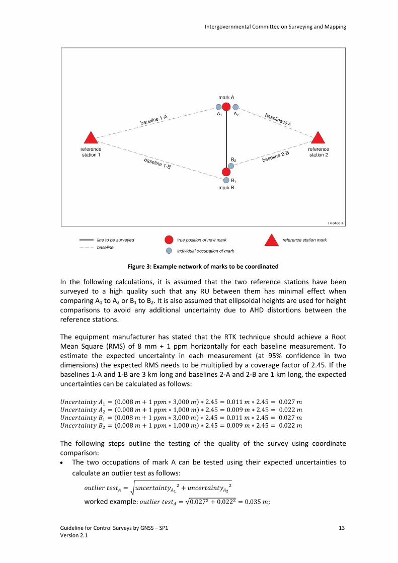
The use of coordinate comparison is best explained using an example survey as shown in Figure 3. The survey requires new marks (A and B) to be coordinated with a horizontal SU of A and B of 0.020 m (at 95% confidence) and a horizontal RU between A and B of 0.030 m (at 95% confidence). The surveyor establishes a GNSS base receiver at reference station 1 and uses a GNSS rover receiver to occupy marks A and B. The base receiver is then moved to reference station 2 and marks A and B are reoccupied. So for mark A, the first occupation measures baseline 1-A resulting in coordinates at A1 and the second occupation measures baseline 2-A resulting in coordinates at A2. Similarly, B1 and B2 represent the two occupations of mark B.
Intergovernmental Committee on Surveying and Mapping
Guideline for Control Surveys by GNSS – SP1 13 Version 2.1
Figure 3: Example network of marks to be coordinated
In the following calculations, it is assumed that the two reference stations have been surveyed to a high quality such that any RU between them has minimal effect when comparing A1 to A2 or B1 to B2. It is also assumed that ellipsoidal heights are used for height comparisons to avoid any additional uncertainty due to AHD distortions between the reference stations.
The equipment manufacturer has stated that the RTK technique should achieve a Root Mean Square (RMS) of 8 mm + 1 ppm horizontally for each baseline measurement. To estimate the expected uncertainty in each measurement (at 95% confidence in two dimensions) the expected RMS needs to be multiplied by a coverage factor of 2.45. If the baselines 1-A and 1-B are 3 km long and baselines 2-A and 2-B are 1 km long, the expected uncertainties can be calculated as follows: ( ) ( ) ( ) ( )
The following steps outline the testing of the quality of the survey using coordinate comparison: The two occupations of mark A can be tested using their expected uncertainties to
calculate an outlier test as follows:
√
worked example: √ ;

Intergovernmental Committee on Surveying and Mapping
Guideline for Control Surveys by GNSS – SP1 14 Version 2.1
Therefore, if the horizontal distance between the coordinates of each occupation, A1 and A2, is less than or equal to the outlier test (0.035 m in the example above), it is reasonable to conclude that the equipment and technique are performing according to manufacturer’s specifications and that neither measurement to mark A is an outlier.
If the difference between the two occupations does not pass the outlier test then a new independent occupation should be made. Note that consistently failing the outlier test at multiple marks may indicate a problem with the coordinates of one or both of the reference stations; indeed, the errors from each reference station should be analysed and any systematic bias should be noted and/or corrected.
Having made two occupations that pass the outlier test, one can take a mean of the two sets of coordinates (A1 and A2) and the SU of that mean can be estimated as follows:
√(
)
worked example: √( ) ; The quality of the two occupations of mark B can then be tested in a similar manner to mark A, such that:
The uncertainties for the two occupations of mark B are used to calculate an outlier test for B1 and B2 using the same formula as for mark A. (worked example: );
Assuming the outlier test is passed, the SU for the mean coordinates from the two occupations of mark B can also be calculated as for mark A. (worked example: m);
Having removed or/or re-observed any outlier observations, the expected RU between marks A and B can be calculated:
√
worked example: √ ; It is then up to the surveyor to decide whether the SU of the marks and the RU between marks A and B meets the specification of the Control Survey. In the example above, the SU of each mark, at 0.017 m, is better than 0.020 m and the RU between A and B is 0.025 m, which is better than 0.030 m and therefore satisfies the survey’s requirements. If the RU achieved between marks did not meet the requirements of the survey, the design of the RTK survey can be improved by:
Improving the estimated uncertainty in the measurements by reducing the distance between the reference station and the new marks (e.g. moving reference station 1 closer in the example), or;
Improving the SU of the mean coordinates by adding an additional independent occupation at each mark.
The final step in evaluating the quality of the real-time GNSS survey is to estimate horizontal PU of each new mark based on the SU of the mean coordinates and the horizontal PU of the nearest reference station. Using reference station 2 in the example above, the horizontal PU of mark A can be estimated as:

Intergovernmental Committee on Surveying and Mapping
Guideline for Control Surveys by GNSS – SP1 15 Version 2.1
√
worked example assuming m : √ ; All of the above calculations apply to the horizontal coordinates and uncertainties. Similar calculations can be used to test the quality of the GNSS ellipsoidal height measurements at marks A and B. Those calculations would use the RMS for heights as stated by the manufacturer (e.g. 15 mm + 1 ppm). To calculate the expected uncertainties in ellipsoidal height measurements, the manufacturer’s RMS values should be multiplied by a coverage factor of 1.96 (for 95% confidence in one dimension). The following example shows the calculation of uncertainty in the height measurement for the baseline 1-A:
( )
The ellipsoidal height uncertainty for the other baselines can be calculated in a similar way and then used to calculate the outlier tests, then the SU for the mean ellipsoidal heights, the RU of the ellipsoidal height difference between A and B and the PU of the ellipsoidal heights of marks A and B.

Intergovernmental Committee on Surveying and Mapping
Guideline for Control Surveys by GNSS – SP1 16 Version 2.1
6 AUSPOS online GPS processing service
ICSM recommends the use of AUSPOS for online GNSS processing. AUSPOS, which is hosted by Geoscience Australia (GA), allows users to submit dual frequency GPS RINEX data observed in static mode and receive coordinates with respect to GDA94 and ITRF. See http://www.ga.gov.au/geodesy/sgc/wwwgps/ for details.
GPS RINEX data submitted online is processed together with surrounding NGRS CORS sites, and if required, International GNSS Service (IGS) CORS sites. The GNSS equipment, observation techniques and processing procedures implemented within the AUSPOS processing environment are suitable for obtaining SU as outlined in Section 3.
As with other online processing services, GPS RINEX data submitted to the AUSPOS service will be rejected if the data fails to meet AUSPOS minimum data quality standards and minimum session length requirements. Users of AUSPOS intending to conform to this Guideline are encouraged to refer to the AUSPOS data processing instructions for full details on survey data requirements, system usage and stated uncertainties.
In addition, ICSM recommends that validation procedures (such as independent occupations) be incorporated to verify the derived results.