guided by - mechanical srpecmechanical.srpec.org.in/files/project/2015/11.pdf · guided by: prof....
TRANSCRIPT

Design and Fabrication of Roll Cage
of a Car
Guided by:
Prof. Jayendra. B. Patel
Prepared by:Mr. Darshan J. Patel 110780119036
Mr. Prajesh S. Kapadiya 120783119023
Mr. Vivek G. Bavisi 110780119034
Mr. Deepak M. Nair 120783119005

List of Content Abstract
Introduction
Literature review
Methodology
Design of „ROLL CAGE‟
Material Selection
Analysis of „ROLL CAGE‟
Fabrication of „ROLL CAGE‟
Conclusion
Application
References

Abstract

Abstract
Our study aims to design, develop and fabricate a
roll cage, in accordance with the SAE. A roll cage is
a skeleton of an All-Terrain Vehicle (ATV). The roll
cage is the Structural base which protects the
occupant in case of impact and roll over incidents.
Here we are going to deal with design of roll cage
for an ATV considering various loading tests like
Front Impact, Side Impact and Rear Impact. We have
focused on every point of roll cage to improve the
performance of vehicle without failure of roll cage.
Finally the roll cage will be fabricated as per the
tools and techniques available in our workshop.
Introduction
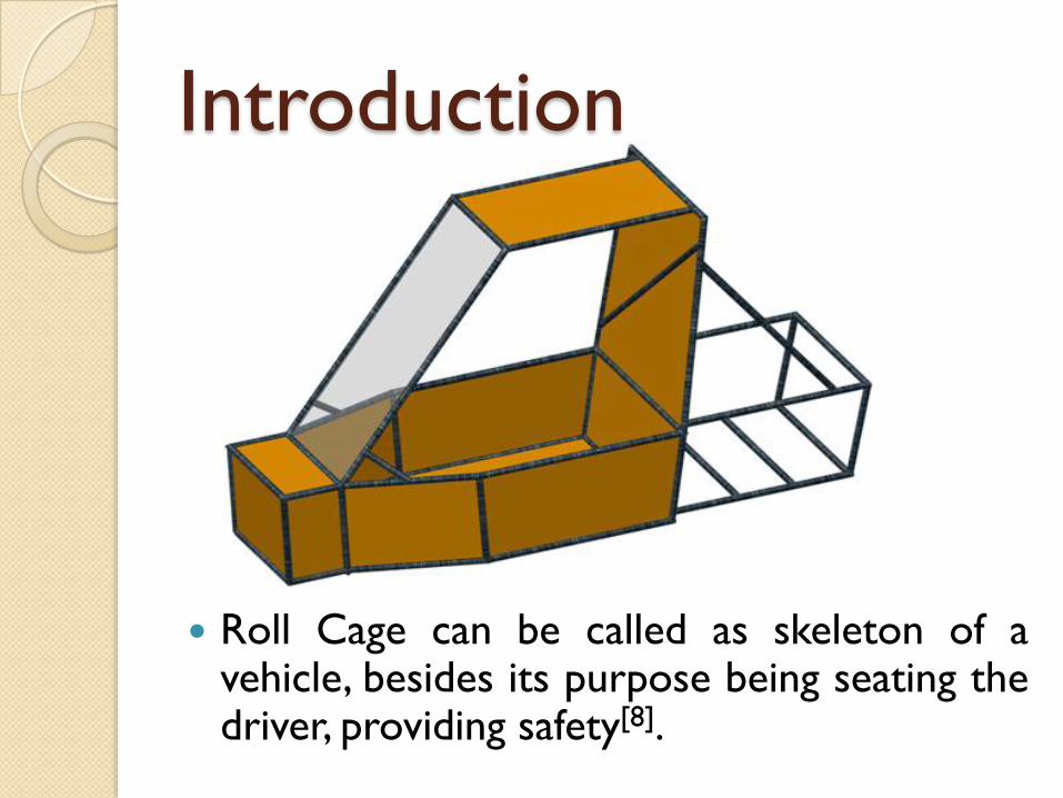
Roll Cage can be called as skeleton of avehicle, besides its purpose being seating thedriver, providing safety[8].

Introduction ATV means a all terrain vehicle which is specially designed
for a off roads driving.
ATV is designed for very rough terrain, jumps, endurance.
The design process of this single-person vehicle is iterative
and based on several engineering and reverse engineering
processes.
Following are the major points which were considered for
designing the off road vehicle:
o Endurance
o Safety and Ergonomics.
o Market availability.
o Cost of the components.
o Standardization
o Safe engineering practices.

Introduction◦ Project Objectives
The main objectives behind our project are as followed:
To design a safest vehicle for the driver.
To design in accordance with the Rulebook.
To design for the driver‟s compatibility.
For optimum stability of the vehicle.
To reduce the weight and maintain a desired centre of
gravity.
To maintain stability in turns.
For prevention from front collision, rear collision, side
collision and rolling.

Literature review

Literature review Denish S. Mevawala et al[1] determined the roll cage not only forms
the structural base but also a 3-D shell surrounding the occupant which protects the occupant in case of impact and roll over incidents. The roll cage also adds to the aesthetics of a vehicle. This paper deals with design of roll cage for an ATV and Various loading tests like Front Impact, Side Impact and rear impact have been conducted. They have focused on every point of roll cage to improve the performance of vehicle without failure of roll cage.
They concluded after the analysis that roll cage structure for its strength against the collision from front, rear, as well as side. Factor of safety is under the safe limit. The roll cage is sustained 4G force from front as well as rear & 2G force from side. But, deformation & stresses are under the limit
Key Words : design of roll cage, loading tests, Front Impact, Side Impact and rear impact

Literature review Thanneru Raghu Krishna Prasad et al.[2] designed the frame &
suspension of the Society of Automotive Engineers (SAE) Baja car which
is a single-seated all-terrain vehicle and is used for off road usage and
endurance on a rough terrain. In many aspects it is similar to an All-
Terrain Vehicle (ATV) except that it is much smaller in size and has safer
rollover capabilities. The modeling of the frame and suspension is done by
using pro-e software. This design is checked by Finite Element Analysis
after estimating the load and the weight of the frame.
They decided that the usage of solidworks® was very helpful to the
design and analysis of the frame and suspension for Mini Baja Car. the
finite element analysis gave a very accurate prediction of where
failure would occur in this situation.
Key Words : SAE® Baja car, design, analysis

Literature review Khelan Chaudhari et al.[3] studied about design, development
and fabrication of the roll cage for All - Terrain Vehicle accordance with
the rulebook of BAJA 2013 given by SAE. Material for the roll cage was
selected based on strength, cost and availability. The roll cage was
designed to incorporate all the automotive sub-systems. A software
model is prepared in Pro-engineer. Based on the result obtained from
these tests the design was modified accordingly. After successfully
designing the roll cage, it was fabricated.
They concluded that the design, development and fabrication of the roll
cage was carried out successfully. The roll cage was used to build an ATV
by integrating all the other automotive systems like transmission,
suspension, steering, brakes and other miscellaneous elements.
Key Words : strength, cost, availability, Pro-engineer®, fabrication
Literature review GAURAV S. CHIMOTE et al.[4] stated that the objective of
their design and analysis of an ATV was fun to drive, versatile, safe,
durable and was also a high performance off road vehicle. They ensured
that the vehicle spastics the limits of set rules. Their vehicle was capable
of negotiating the most extreme terrain with confidence and ease. They
met these objectives by dividing the vehicle into major component
subsystems.
They concluded that when undertaking design of any vehicle there were
several factors to be considered that were common to all engineering
vehicles.
Key Words : versatile, safe, durable, negotiating extreme terrain

Literature review Puneet Malhotra et al [5] stated that their study was to design of
an All-Terrain Vehicle (ATV) in accordance with the SAE BAJA 2014 rule
book. A detailed designing of components were carried out by them like
Roll cage, Suspensions & Braking mechanism. The main focus of their
was on Safety of driver & Stability of vehicle. Roll cage of their vehicles
was designed in such a way that in case of rolling of vehicle (mostly
occurs in high speed turns & off roading that it will provide double the
strength to the roll cage with also considering the Aesthetic of the cage.
International standards were followed by them where ever possible and
an extensive market survey was also done. Finite Element Analysis was
carried out on roll cage & braking mechanism for optimum safety &
reliability of the vehicle.
Key Words : Safety of driver, Stability of vehicle, optimum safety,
reliability of the vehicle.
Literature review Sanjay Sharma et al [6] stated that the main objective
of their research work was to find the mode, shape, and
corresponding natural frequency of a roll cage for an ATV.
Finite element analysis is used to determine the mode
shapes and frequencies. They have designed a roll cage
which consists of both structural base and 3-D shell which
protects the user in case of impact and roll over incidents.
CATIA V5 was been used for modelling the roll cage and
ANSYS 14.5 for FEA analysis. The body shape of the roll
cage was fixed from the front end. The frame of the roll cage
consists of three main parts known as boot space, driver
cabin and engine chamber.
Key Words : Finite Element Analysis, Ansys®

Project Methodology

Define the Project
Study about SAE BAJA Vehicle
Select the design methodology
Select Material of the ‘ROLL CAGE’ structure
Design of ‘ROLL CAGE’
Analysis of ‘ROLL CAGE’
Based on Result, Implementation in ‘ROLL CAGE’ Design
Analysis of Final Design
Fabrication of ‘ROLL CAGE’

Design of „ROLL CAGE‟

Roll Cage Structure
We have designed all Roll Cage designs in
software „Creo parametric 2.0‟
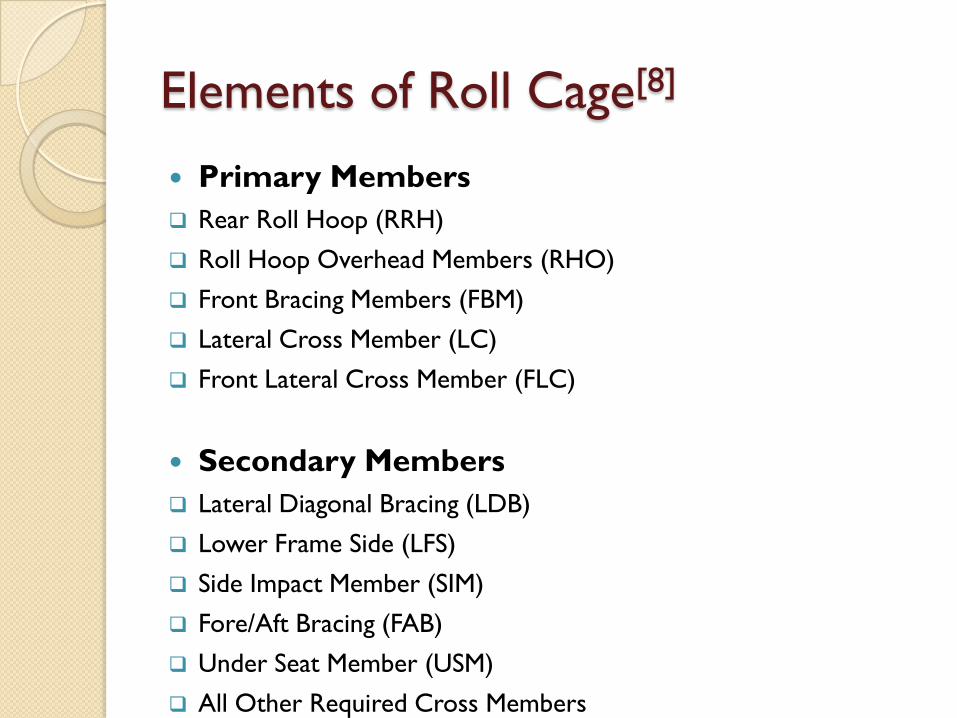
Elements of Roll Cage[8]
Primary Members
Rear Roll Hoop (RRH)
Roll Hoop Overhead Members (RHO)
Front Bracing Members (FBM)
Lateral Cross Member (LC)
Front Lateral Cross Member (FLC)
Secondary Members
Lateral Diagonal Bracing (LDB)
Lower Frame Side (LFS)
Side Impact Member (SIM)
Fore/Aft Bracing (FAB)
Under Seat Member (USM)
All Other Required Cross Members

Elements of Roll Cage[8]
Fig. 1 Elements of the Roll Cage
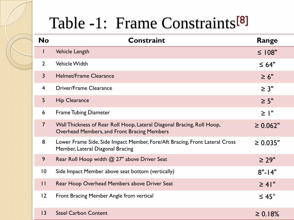
Table -1: Frame Constraints[8]
No Constraint Range
1 Vehicle Length ≤ 108"
2 Vehicle Width ≤ 64"
3 Helmet/Frame Clearance ≥ 6"
4 Driver/Frame Clearance ≥ 3"
5 Hip Clearance ≥ 5"
6 Frame Tubing Diameter ≥ 1"
7 Wall Thickness of Rear Roll Hoop, Lateral Diagonal Bracing, Roll Hoop,
Overhead Members, and Front Bracing Members≥ 0.062"
8 Lower Frame Side, Side Impact Member, Fore/Aft Bracing, Front Lateral Cross
Member, Lateral Diagonal Bracing≥ 0.035"
9 Rear Roll Hoop width @ 27" above Driver Seat ≥ 29"
10 Side Impact Member above seat bottom (vertically) 8"-14"
11 Rear Hoop Overhead Members above Driver Seat ≥ 41"
12 Front Bracing Member Angle from vertical ≤ 45°
13 Steel Carbon Content ≥ 0.18%

Design :
Top view
Side view
Default view
All dimensions are in
INCH

Tube sizes: Outer Diameter: 25.4 mm (1.00”)
Wall Thickness: 2 mm (0.078”)
Then design of the roll cage considering AISI 1018 Mild
Steel pipes of shown dimensions was done and we
might get the factor of safety more than 2, which could
justified the selection.
Tube Specification
Fig. 2 Designed model of tube in Creo 2.0®

We have selected AISI 1018 mild low carbon steel for
the fabrication of the roll cage.
Material Specification
Element Content
Carbon, C 0.14 – 0.20 %
Iron, Fe 98.81 – 99.26 %
Manganese, Mg 0.60 – 0.90%
Phosphorous, P ≤ 0.040 %
Sulfur, S ≤ 0.050 %
Chemical Composition[10]
Table-2: Chemical Composition of AISI 1018 mild low carbon steel

Material Specification
Mechanical Unit value
Tensile Strength, Ultimate 440 MPa
Tensile Strength, Yield 365 MPa
Elongation 15.0%
Modulus of Elasticity 205 GPa
Machinability 70 %
Physical Properties[10]
Table-3: Physical Properties of AISI 1018 mild low carbon steel

Analysis of „ROLL CAGE‟

Impact load calculation
After finalizing the frame along with its material and
cross section, it is very essential to test the rigidity and
strength of the frame under severe conditions. The
frame should be able to withstand the impact, torsion,
roll over conditions and provide almost safety to the
driver without undergoing much deformation. Following
tests were performed on the roll cage.
◦ (i) Front impact
◦ (ii) Rear impact
◦ (iii) Side impact
◦ (iv) Longitudinal Torsion

(i) Front & Rear Impact Calculation[1] : Front and rear impact or the static front and rear impact analysis, Deceleration
of 4G‟s was assumed for the loading which is equivalent to a static force of
11772 N (equivalent to 12000 N) load on the vehicle, assuming the weight of
the vehicle is 300 kg (with including 130 kg driver weight). We apply 12000 N
from the front for the test of front impact and rear for the test of rear impact
of the roll cage structure of the vehicle for determining strength at the time of
front and rear collision.
F = m*a
= 300* (4*9.81)
= 11772 N (equivalent to 12000 N)
Fig. 3 Constraint for front impact analysis Fig. 4 Constraint for rear impact analysis

After the analysis of front impact the maximum deformation found to be
0.829mm as shown in fig.1 andVon-Mises Stress is 128.23 MPa as shown in fig.2.
After the analysis of rear impact the maximum deformation found to be
2.514mm as shown in fig.3 Von-Mises Stress is 165.58 MPa as shown in fig.4.
Fig. 6 Stress analysisFig. 5 Total Deformation analysis
Fig. 8 Stress analysisFig. 7 Total Deformation analysis
(i) Front & Rear Impact Analysis :
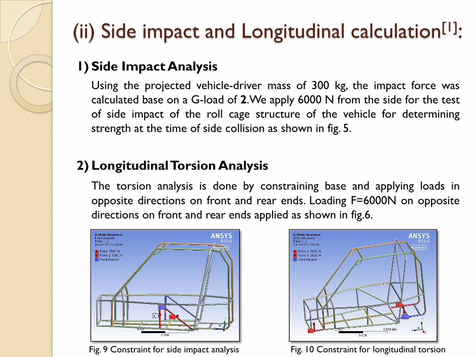
(ii) Side impact and Longitudinal calculation[1]:
Fig. 9 Constraint for side impact analysis Fig. 10 Constraint for longitudinal torsion
1) Side Impact Analysis
Using the projected vehicle-driver mass of 300 kg, the impact force was
calculated base on a G-load of 2.We apply 6000 N from the side for the test
of side impact of the roll cage structure of the vehicle for determining
strength at the time of side collision as shown in fig. 5.
2) LongitudinalTorsion Analysis
The torsion analysis is done by constraining base and applying loads in
opposite directions on front and rear ends. Loading F=6000N on opposite
directions on front and rear ends applied as shown in fig.6.

(ii) Side impact and Longitudinal Analysis :
After the analysis of side impact the maximum deformation found to be
3.022mm as shown in fig. 7 andVon-Mises Stress is 188.06 MPa as shown in fig.8.
After the analysis of longitudinal torsional loading the maximum deformation
found to be 1.41mm as shown in fig.9 and Von-Mises Stress is 148.75 MPa as
shown in fig.10.
Fig.11 Total Deformation analysis Fig.12 Stress analysis
Fig.13 Total Deformation analysis Fig.14 Stress analysis

Results After the calculating maximum Von-Mises Stress define the Factor of Safety
(F.O.S) by using equation:
Incorporated Factor of Safety = σyt/σmax[1]
Factor of safety as well as deformation of the roll cage at different applied
load condition is as shown in table-4. Since FOS are under the limit, hence
design is safe against specified Forces.
Table -4: Finite Element Analysis Results
SR. NO. 1. 2. 3. 4.
TEST Front Impact Rear Impact Side ImpactLongitudinal
Torsion
FORCE APPLIED (N) 12,000 12,000 6,000 6,000
YIELD STRENGTH-
σyt (MPA)365 365 365 365
VON -MISSES
STRESS-σmax (MPA)128.23 165.58 188.06 148.75
FACTOR OF SAFETY 2.84 2.20 1.94 2.45
TOTAL
DEFORMATION (mm)0.829 2.514 3.022 1.41
RESULT No Yielding No Yielding No Yielding No Yielding

Fabrication of „ROLL CAGE‟

Fabrication of „ROLL CAGE‟
From the results of the above tests it is concluded that
the roll cage is safe under severe conditions. After the
static analysis of the roll cage, material procurement
was done.
Total 7 tubes of 6m length each were procured at a cost
of Rs. 5000. The cost per kg was Rs. 70.
The material was cut and machined to required
dimensions.
Rail cutter available in the workshop was used to serve
the purpose.

Fabrication of „ROLL CAGE‟
After analyzing the material joining techniques available
in the college workshop, metal arc welding was selected.
All the members of the roll cage can be joined by this
technique. The advantages of this welding technique are
as follows:
It is the simplest of all arc welding processes.
The equipment is portable and the cost is fairly low.
A big range of metals and their alloys can be welded.

Fabrication of „ROLL CAGE‟
Fig. 15 Model of Fabricated Roll cage

Conclusion
After having lots of study, efforts and observations we
came to the conclusion that our project results into
light weight compared to other roll cages, reduced
space requirements, reduction in material wastage,
reduction in cost, multiple usage, easy for
implementation, survival in un-ground surfaces and gives
safety to the driver for smooth driving.
Finally we have completed Fabrication of the Roll Cage
of a Car as per design in this semester.

Application
Roll cage can be used to reduce weight as well as for
safety purpose of Driver[9].

Application Such roll cage can also been used in SAE-BAJA or SAE-
Supra racing events.

ReferencesPapers [1] Denish S. Mevawala, Mahesh P. Sharma, Devendra A. Patel, Darshan A. Kapadia IOSR
Journal of Mechanical and Civil Engineering (IOSR-JMCE) e-ISSN: 2278-1684, p-ISSN: 2320-
334X PP 49-53 www.iosrjournals.org-“ Stress Analysis of Roll Cage for an All Terrain
Vehicle”.
[2] Thanneru Raghu Krishna Prasad, Goutham Solasa, Nariganani SD Satyadeep, G.Suresh
Babu – International Journal of Engineering and Advanced Technology (IJEAT) ISSN: 2249 –
8958, Volume-2, Issue-5, June 2013 – “Static Analysis and Optimisation of Chassis and
Suspension of an All-TerrainVehicle”
[3] Khelan Chaudhari, Amogh Joshi, Ranjit Kunte, Kushal Nair-Paper Series from SAE
TECHNICAL, Series No : 2002-01-3300. INDIAN PATENT.- “Design and Development of
Roll Cage For A All-TerrainVehicle.
[5] Harsh Raghuvanshi, N.S. Ramnaveen, Puneet Malhotra, Rakshit, Anurag Khatri
International Journal of Engineering and Advanced Technology (IJEAT) ISSN: 2249 – 8958,
Volume-3, Issue-2, December 2013 –“Innovative Design of an All-Terrain Vehicle (ATV)”.
[6] Akshit Goyal, Milap Singh, Sanjay Sharma INTERNATIONAL JOURNAL OF
SCIENTIFIC & TECHNOLOGY RESEARCH VOLUME 3, ISSUE 6, JUNE 2014 ISSN 2277-
8616 – “Free Vibration Mode Shape Analysis And Fabrication Of The Roll Cage For All-
Terrain Vehicle Based On FEA”.

References [8] 2015 SAE-BAJA INDIA RULES: http://www.bajasaeindia.org “Brief history of SAE
BAJA”
[9] AUTOMOBILE ENGINEERING by H.G. Katariya and J.P. Hadiya - BOOKS INDIA
PUBLICATION – II EDITION.“About Roll Cage”
[10] www.engineersedge.com
