guide to nickel aluminium bronze for engineers - copper · pdf file2 | guide to nickel...
TRANSCRIPT

Guide to Nickel Aluminium Bronze
for Engineers

2 | GUIDE TO NICKEL ALUMINIUM BRONZE FOR ENGINEERS
Guide to Nickel Aluminium Bronze for EngineersIvan Richardson, edited by Carol Powell
Copper Development Association is a non-trading organisation that promotes and supports the use of copper based on its superior technical performance and its contribution to a higher quality of life. Its services, which include the provision of technical advice and information, are available to those interested in the utilisation of copper and copper alloys in all their aspects. The Association also provides a link between research and the user industries and is part of an international network of trade associations, the Copper Alliance™.
Cover page images:
Adjustable bolted propeller – one of two 33 tonne propellers from the Queen Elizabeth class aircraft carrier capable of producing 40 MW of thrust (Courtesy Rolls Royce Marine)
Nickel aluminium bronze window frames, cladding and roof, Portcullis House, London
Seawater pipe sections (Courtesy Inoxyda SA, France)
Copper Development Association Publication No 222 January 2016
Acknowledgements:Copper Development Association would like to acknowledge the assistance of John Bailey, Roger Francis, John Galsworthy, Dominic Meigh, Carol Powell, Ladji Tikana, Clive Tuck and Peter Webster in the production of this publication.
DisclaimerWhilst this document has been prepared with care, we can give no warranty regarding the contents and shall not be liable for any direct, incidental or consequential damage arising out of its use. For complete information on any material, the appropriate standard should be consulted.
Copyright © 2016. Copper Development Association

GUIDE TO NICKEL ALUMINIUM BRONZE FOR ENGINEERS | 3
Contents
1.0 Introduction...............................................5
2.0 Overview ....................................................6
2.1 Typical Mechanical and Physical Properties ...............72.2 Seawater Corrosion Behaviour ........................................82.3 Development Chronology ..................................................8
3.0 Applications .............................................10
3.1 Aerospace ...............................................................................103.2 Architecture ...........................................................................113.3 Marine ......................................................................................11 3.3.1 Defence ...................................................................11 3.3.2 Commercial ...........................................................133.4 Offshore Oil/Gas and Petrochemical ...........................14 3.4.1 Bearing Applications within Oil Rig Equipment .............................................................15 3.4.2 Communications and Transponders ...........17 3.4.3 Actuator Valves ...................................................18 3.4.4 Oil Tankers .............................................................183.5 Desalination and Water Condenser Systems ...........19
4.0 Alloying Elements and Microstructural Phases ...........................21
4.1 Influence of Alloying Elements ......................................214.1.1 Aluminium .............................................................214.1.2 Manganese ............................................................214.1.3 Nickel .......................................................................214.1.4 Iron ...........................................................................214.1.5 Impurities ..............................................................21
4.2 Types of Microstructural Phases ...................................21
5.0 Properties ................................................ 26
5.1 Mechanical Strength ..........................................................265.2 Low and High Temperature Properties .......................275.3 Impact Toughness ...............................................................275.4 Fatigue Strength ..................................................................285.5 Creep Strength .....................................................................295.6 Magnetic Permeability ......................................................30
6.0 Corrosion Resistance ............................. 32
6.1 Protective Surface Film .....................................................32 6.1.1 Oxidation at Elevated Temperatures...........326.2 Pitting.......................................................................................32 6.3 Crevice Corrosion ................................................................326.4 Selective Phase Corrosion ................................................336.5 Galvanic Corrosion .............................................................346.6 Biofouling ...............................................................................366.7 Electrical Leakage (Stray Current) Corrosion ...........376.8 Sulphide Pollution ...............................................................37
6.9 Comparative Corrosion Resistance of Various Copper-based Alloys in Seawater Applications ......386.10 Erosion Corrosion ................................................................396.11 Cavitation ...............................................................................396.12 Stress Corrosion Cracking ................................................406.13 Corrosion Fatigue ................................................................416.14 Comparison in Seawater with Other Alloy Groups .....................................................................................436.15 Corrosion Resistance of Nickel Aluminium Bronze in Chemical Environments ...............................44
6.15.1 Sulphuric Acid .....................................................446.15.2 Acetic Acid ............................................................446.15.3 Hydrochloric Acid ...............................................446.15.4 Phosphoric Acid ..................................................446.15.5 Hydrofluoric Acid ...............................................456.15.6 Nitric Acid ..............................................................456.15.7 Alkalis ......................................................................456.15.8 Salts .........................................................................456.15.9 Other Corrosive Chemical Environments .......................................................45
6.16 Weld Areas .............................................................................466.16.1 Galvanic Corrosion ............................................466.16.2 Selective Phase Attack .....................................466.16.3 Stress Corrosion ..................................................466.16.4 Porosity and Gas Inclusions ...........................46
7.0 Heat Treatment ...................................... 47
7.1 Stress Relieving .........................................................................477.2 Annealing .....................................................................................477.3 Quenching and Tempering ...................................................487.4 Heat Treatment of Cast CuAl10Fe5Ni5 ............................497.5 Heat Treatments in International Standards.................50
8.0 Wear and Galling Performance ............ 52
8.1 Fretting Wear .............................................................................538.2 Galling ...........................................................................................54
9.0 Fabrication and Manufacture .............. 56
9.1 Welding ...................................................................................569.1.1 Welding Processes ................................................579.1.2 Joining Processes ..................................................579.1.3 Recommended Welding Processes ................57
9.1.3.1 TIG/GTAW Process .............................579.1.3.2 MIG/GMAW Process .........................589.1.3.3 Manual Metal Arc..............................599.1.3.4 Electron Beam Welding ..................609.1.3.5 Friction Welding.................................609.1.3.6 Laser Welding......................................60
9.1.4 Welding Practice and Joint Design ................609.1.4.1 Design of Joints .................................609.1.4.2 Weld Preparation ...............................61

4 | GUIDE TO NICKEL ALUMINIUM BRONZE FOR ENGINEERS
Contents
9.1.5 Pre-heating and Weld Run Temperature Control ..........................................62
9.1.6 Selection of Filler Materials for TIG/GTAW and MIG/GMAW Welding ...........639.1.7 Post Weld Heat Treatment ...............................63
9.1.7.1 Stress Relief ........................................639.1.7.2 Full Anneal ..........................................63
9.2 Machining .............................................................................659.2.1 Rough and Finishing Turning .........................679.2.2 Milling.......................................................................689.2.3 Slot Milling .............................................................699.2.4 Threading ................................................................ 70
9.3 Mechanical and Non-destructive Testing ................ 719.3.1 Mechanical Testing ............................................. 719.3.2 Non-destructive Testing ................................... 71
9.4 Manufacture - Casting Processes ...............................729.4.1 Modern Casting Techniques ............................729.4.2 Continuous Casting Computer Simulation .........................................739.4.3 Continuous Casting ............................................739.4.4 Centrifugal Casting .............................................75
9.5 Wrought Hot Working Processes .................................769.5.1 Hot Working Ranges ..........................................769.5.2 Cold Working .........................................................769.5.3 Extrusion..................................................................769.5.4 Rolling ......................................................................769.5.5 Forging .....................................................................77
10.0 Summary Guidelines for Engineers ...... 79
11.0 References and Further Information ... 80
11.1 General References ............................................................8011.2 Publications from Copper Development Association (CDA) .............................................................. 8111.3 Other Publications .............................................................81
Appendix: Tables 1-22 ................................... 82
Standards, Designations, Chemical Compositions and Mechanical Properties International StandardsTable App1 Nickel Aluminium Bronze - Wrought .............83Table App2 Nickel Aluminium Bronze – Cast ......................85
UK: Nickel Aluminium Bronze - WroughtTable App3 Chemical Compositions ........................................86Table App4 Mechanical Properties ..........................................86
UK: Nickel Aluminium Bronze – CastTable App5 Chemical Compositions ........................................87Table App6 Mechanical Properties ..........................................87
UK/European: Nickel Aluminium Bronze – Wrought Table App7 Chemical Compositions ........................................88Table App8 Mechanical Properties ..........................................89
UK/European: Nickel Aluminium Bronze – CastTable App9 Chemical Compositions ........................................90Table App10 Mechanical Properties ..........................................90
France: Nickel Aluminium Bronze – Wrought Table App11 Chemical Compositions ........................................91Table App12 Mechanical Properties ..........................................91
France: Nickel Aluminium Bronze – CastTable App13 Chemical Compositions ........................................92Table App14 Mechanical Properties ..........................................92
Germany: Nickel Aluminium Bronze – WroughtTable App15 Chemical Compositions ........................................93Table App16 Mechanical Properties ..........................................94
Germany: Nickel Aluminium Bronze – CastTable App17 Chemical Compositions ........................................95Table App18 Mechanical Properties ..........................................95
USA: Nickel Aluminium Bronze – WroughtTable App19 Chemical Compositions ........................................96Table App20 Mechanical Properties ..........................................96
USA: Nickel Aluminium Bronze – CastTable App21 Chemical Compositions ........................................97Table App22 Mechanical Properties ..........................................98
Appendix

1.0 Introduction
Alloys of copper and aluminium are known as aluminium bronze and, together with other alloying additions, produce a range of properties that are beneficial to a diverse range of industries. Of these, the nickel aluminium bronze group of alloys is the most widely used. They have been adapted with time to optimise performance and can provide a combination of properties that can offer an economic alternative to other types of alloy systems.
Nickel aluminium bronzes are available in both cast and wrought product forms and have a unique combination of properties:
• Excellent wear and galling resistance• High strength• Density (10% lighter than steel)• Non-sparking• Low magnetic permeability (of <1.03 µ in selected grades)• High corrosion resistance• Good stress corrosion properties• Good cryogenic properties• High resistance to cavitation• Damping capacity twice that of steel• High resistance to biofouling• A protective oxide surface film which has the ability to self-repair.
End uses range from landing gear bushing and bearings for all of the world’s commercial aircraft to seawater pumps and valves, propellers for naval and commercial shipping, non-sparking tools in the oil and gas industry and pleasing facades in architecture.
The nickel aluminium bronze alloys are fairly complex materials and, during manufacture, require good control of the metal structure by attention to composition and heat treatment. As such it is the purpose of this publication to provide an engineering overview of the properties of the alloys, their specifications and their applications for operators, designers, manufacturers and fabricators. Their corrosion behaviour is explained and guidance is given to obtain optimum service performance. Methods of manufacture, welding and fabrication are also described and a list of references and useful publications is provided. The Appendix covers full details of designations, specifications and related composition and mechanical property requirements.
GUIDE TO NICKEL ALUMINIUM BRONZE FOR ENGINEERS | 5

2.0 Overview
6 | GUIDE TO NICKEL ALUMINIUM BRONZE FOR ENGINEERS
Broadly, the nickel aluminium bronzes can be classified as alloys containing 6-13% aluminium and up to 7% iron and 7% nickel. The more common alloys normally contain 3-6% each of these two elements. Manganese up to approximately 1.5% is also added, both as a deoxidant and a strengthening element. There is a separate family of alloys which contain up to 14% manganese with additions of iron and nickel. They are called here manganese aluminium bronzes and the standard alloy, designated CuMn11Al8Fe3Ni3, is discussed briefly in later sections.
Table 1 below gives an indication of a range of aluminium bronze alloy properties with increasing alloy additions and strength. Alloys CW304G, CW307G and CW308G are nickel aluminium bronzes.
Table 1 - Specification BS EN 12165 Wrought Forgings 6-80 mm Diameter
Alloy Cu %
Al %
Fe %
Ni %
Mn %
Si %
0.2% Proof Strength
N/mm² (MPa)
Tensile Strength
N/mm² (MPa)
Elongation %
HardnessHB
CW305G Rem 9.0-10.0 0.5-1.5 180 420 20 100
CW303G Rem 6.5-8.5 1.5-3.5 1.0 max 180 460 30 110
CW304G Rem 8.0-9.5 1.0-3.0 2.0-4.0 180 500 30 115
CW302G Rem 6.3-7.6 1.5-2.2 250 500 20 120
CW306G Rem 9.0-11.0 2.0-4.0 1.5-3.5 250 500 20 120
CW307G Rem 8.5-11.0 3.0-5.0 4.0-6.0 1.0 max 350 650 12 180
CW308G Rem 10.5-12.5 5.0-7.0 5.0-7.0 1.5 max 450 750 5 190
Since the first manufacture of aluminium bronze in the 1850s, there has been a progressive development in elemental additions to improve the mechanical properties and corrosion resistance. The early alloys were binary systems of copper and aluminium with aluminium in the range 6-11%. Up to about 8-9% aluminium, the equilibrium metal structure is single phase and progressively increases in strength as the aluminium increases. Such alloys were found to be ductile and suitable for cold worked products. At higher aluminium levels, a second phase occurs in the structure at higher temperatures which, when retained by cooling quickly, is stronger and harder with good corrosion resistance and better erosion resistance. Alloys typically containing 9-10% aluminium became noted for their strength but, as their ductility for forming was better at high temperatures, the two phase alloys were more conveniently hot worked. If slow cooled below 565oC, however, the structure alters again, becoming less ductile and also more susceptible to corrosion in seawater.
By 1914 the temper hardening features of aluminium bronze containing nickel were recognised (1). Its presence, together with iron additions to suppress unwanted structural phases, became fully appreciated over the next decade (2) and now forms the basis of the modern complex alloy systems.
The combined additions of iron and nickel are particularly important as they also improve the strength and corrosion resistance. When both are present at nominally 5%, they modify the structure of 9-10% aluminium alloys beneficially and the properties can be further enhanced by quench and temper heat treatments. These are the most popular type of nickel aluminium bronzes for seawater service and a range of wrought and cast product forms is available.
Aluminium has a strong affinity for oxygen. This is important for the corrosion resistance of the alloys as it plays an important part of the surface protective film, but aluminium oxides can also be present as internal inclusions in the metal and historically these inclusions, together with shrinkage cavities formed when the alloys were cast, prevented their initial commercial development. However, in 1913 Pierre Gaston Durville developed a casting method called the ‘Durville process', which became synonymous with the early production of the alloys. This was a non-turbulent mould tilting process which enabled billet and castings to be produced without the detrimental oxide inclusions. In more recent years, the original ‘Durville process' has been superseded by more economic casting processes such as semi and continuous casting methods, where cooling rates and control of oxide inclusions are more sophisticated. Casting methods are discussed in Section 9.4 and Table 4 gives a chronological development of aluminium bronze alloys.

GUIDE TO NICKEL ALUMINIUM BRONZE FOR ENGINEERS | 7
2.1 Typical Mechanical and Physical Properties
Although nickel aluminium bronzes now form the largest family of aluminium bronze alloys worldwide, during their development various countries adopted and manufactured their own versions. Whereas European standards attempted to unify this, major world producers - including the USA, Germany, France and the UK - still use their own standards, mainly for aerospace and military marine applications. Tables App1-22 in the Appendix provide full details of international standards and their designations, compositions and mechanical properties. There is some overlap and many specifications can be dual released, particularly in the aerospace sector.
Table 2 illustrates the properties of one of the most common wrought nickel aluminium bronzes. The composition range in UK, European and USA standards overlap. Mechanical properties are given for two standards to indicate how the strength achievable can differ. Further information and data on mechanical properties are given in Section 5.0 and the Appendix.
Table 2 – Properties of Common Wrought Nickel Aluminium Bronzes
Standards BS EN 12163 ASTM B150 AMS 4640 Def Stan 02-833
Alloy Designation CW307G C63000 C63000 Def Stan 02-833
Composition Ranges Cu Rem, Al 8.5-11%, Ni 4.0-6.0%, Fe 2.0-5.0%, Mn 1.5% max
Physical Properties*
Density 7590 kg/m³
Melting range 1060-1075°C
Hot working range 705-925°C
Thermal conductivity 42 W/m°K
Electrical resistivity 0.13 µΩ.m
Coefficient of linear expansion (20-200°C) 17.1 x 10⁻⁶/°C
Specific heat 420 J/kg/K
Magnetic permeability 1.5 µ
Mechanical Properties at Room Temperature Def Stan 02-833* Hot Rolled Bar 50 mm Dia
AMS 464050 mm Wrought
0.2% Proof strength 295 N/mm² (MPa) 414 N/mm² (MPa)
Tensile strength 635 N/mm² (MPa) 758 N/mm² (MPa)
Shear strength 415 N/mm² (MPa)
Vickers hardness 200 HV
Elongation 17% 10%
Impact toughness at room temperature 23-27 Joules
Modulus of elasticity 125 GPa
Modulus of rigidity 49 GPa
Poisson’s ratio 0.32
Fatigue limit in air 10 7 cycles 278-293 N/mm² (MPa)
* Data is taken for Def Stan 02-833 from Def Stan 02-879 Part 2, which is not a manufacturing specification for nickel aluminium bronze but contains advisory material property data sheets.

8 | GUIDE TO NICKEL ALUMINIUM BRONZE FOR ENGINEERS
2.2 Seawater Corrosion Behaviour
Nickel aluminium bronze is widely used in seawater systems, particularly as cast valve bodies, pump casings and impellers. Corrosion resistance of the alloys relies on a complex copper-aluminium thin adherent oxide surface film, which acts as a protective barrier and is self-repairing, even down to very low levels of oxygen in the service environment. Of the copper alloys, they have high resistance to flow and a high order of resistance to ammonia stress corrosion cracking. They have excellent resistance to cavitation and are an established alloy for ship propellers.
Selective phase corrosion (also known as de-aluminification) has been observed at crevices and other shielded areas, particularly in cast alloys. This can be avoided by galvanic coupling to less noble alloys or by ensuring exposure to aerated flowing seawater when first immersed in seawater so that protective films in surrounding areas become established. Selective phase corrosion will be explored again in more detail in Section 6.4.
As with all copper alloys, extended exposure to polluted or putrefied water should be avoided as they experience higher corrosion rates in the presence of sulphides.
Other general corrosion data is given in Table 3. Although specific to UK Defence Standard 02-879, the data is a guide to other specifications within the CuAl10Ni5Fe4 family of alloys.
Table 3 – General Corrosion Data (Full Immersion in Seawater) ex UK Def Stan 02-879 Part 1 Issue 1 (3)
Free corrosion potential -0.25 VSCE
Corrosion rate 0.05-0.075 mm/year
Impingement resistance Up to 4.3 m/sec
NB: Nickel levels equal or greater than those of iron are believed to increase corrosion resistance
The high manganese aluminium bronze alloy CuMn11Al8Fe3Ni3 is used primarily as cast propellers in marine environments as it has a higher resistance to erosion corrosion (4). However, it has a lower resistance to selective phase corrosion than nickel aluminium bronze and is not advised for static or shielded area crevice conditions.
2.3 Development Chronology
The invention of electromagnetic induction and electrical generators in the 1800s was the catalyst for the rapid development of modern metal processing – see Table 4.
Table 4 – Chronology
1856 An English metallurgist John Percy had observed: “A small proportion of aluminium increases the hardness of copper, does not injure its malleability, makes it susceptible of a beautiful polish and varies its colour from red-gold to pale yellow.”
1856 Aluminium bronze was produced in France by the Tissier brothers of Rouen, but was too expensive to manufacture on a commercial scale.
1885 The Cowles brothers in the USA produced aluminium bronze at a lower cost, with a process using electricity and reducing corundum, an oxide of aluminium with the aid of charcoal in the presence of granulated copper. They also set up a subsidiary in Milton close to Stoke-on-Trent, UK and, between the two companies, they produced six grades of aluminium bronze.
1886 Charles Hall and Paul Héroult, working independently, successfully produced aluminium by an electrolysis process at an economic price, enabling aluminium bronze to be manufactured more commercially.
1887 Héroult took out the first patent for aluminium bronze as an indirect method of producing aluminium by electrolysing alumina as the anode and copper as the cathode.
1887 The commercial production of aluminium bronze by this indirect method was relatively short-lived with the more economic direct production of aluminium by the Pittsburgh Reduction Company at Niagara Falls using the Hall process. The company went on to become Alcoa with the commercial production of aluminium. From this point on manufacturers chose to make their own alloys, which led to a growth in production in the form of castings, forgings and rolled bar.

GUIDE TO NICKEL ALUMINIUM BRONZE FOR ENGINEERS | 9
1893 Design engineers at Westinghouse Machine and Air Brake Company in the USA started to use aluminium bronze in corrosion applications.
1894 Alexander Dick invented the copper alloy extrusion press as we know it today and he went on to form the Delta Metal Company in the UK. However, it was not until the 1930s that presses were designed large enough to extrude aluminium bronze (5).
1910 Lantsberry and Rosenhain from the National Physical Laboratory, UK, researched manganese additions, which were found to have a strengthening effect and also acted as a deoxidant.
1913 In France Pierre Gaston Durville set up a company called Bronzes et Alliages Foreables SA in which he used his new patent casting method known as the ‘Durville process’, which went on to revolutionise the production of aluminium bronze billet. The tilting furnace and mould method prevented the turbulent flow of metal which had caused many problems in past production, due to oxide inclusions.
1914 Read and Greaves reported the temper hardening features of aluminium bronze containing 10% aluminium and upwards of 2% nickel (6).
1923 Charles Meigh, after 4 years with the Durville company, set up his own foundry near Rouen in France called Forge et Founderie d’Alliages de Haute Resistance. He modified the Durville process to incorporate a tilting sand mould to the tilting furnace.
1928 Genders, Reader and Foster conducted work on some true complex cast nickel aluminium bronzes, CuAl9Fe6Ni6, CuAl10Fe3Ni3Mn3 (2).
1934 Continuous casting was used for copper alloys when the German Siegfried Junghans invented the reciprocating mould which was used at the Wieland-Werke company. During the same period in the USA, Byron Eldred invented the use of graphite as a mould material, which later went on to become part of the modern continuous casting method for aluminium bronze.
1937 Charles Meigh returned to England and set up a new company called Meigh of Cheltenham, which later became Meigh Castings. He also set the Meigh’s process at Chatham Naval Dockyard, where the British Admiralty had taken a great interest in the use of aluminium bronze for marine applications.
1937 Gough and Sopwith conducted research on fatigue and corrosion fatigue of some special bronzes including forged CuAl10Fe5Ni5 (7).
1939-45 The onset of the Second World War was a major catalyst for the mass production of the nickel aluminium bronzes with companies such as Meigh’s, Birkett Billington & Newton and Manganese Bronze in the UK, Ampco Metals in the USA and Le Bronze in France producing cast and wrought products.
1951 The first nuclear submarine, USS Nautilus (SSN-571) was built by General Dynamic at their Electric Boat facility at Groton. The boat incorporated nickel aluminium bronze and the design and build was overseen by Admiral Rickover.
1967 The rise in the price of oil and the control by OPEC led to oil exploration offshore in the Gulf of Mexico and the North Sea, which created new demand for nickel aluminium bronze for pumps, valves and fire control equipment.
1978 The deregulation of commercial aerospace regulations in the USA promoted a major growth in low cost airlines. In Europe this was not completed until 1997. However, the outcome of both these processes gave rise to a steady 5-6% year-on-year growth, starting from the boom years of the early 1980s. Both cast and wrought aluminium bronzes were used extensively in the landing bushing and bearings of all commercial world aircraft.
1980 – present
Aerospace, defence, commercial marine and the petrochemical industrial sectors continue to remain the major outlets for nickel aluminium bronze.

10 | GUIDE TO NICKEL ALUMINIUM BRONZE FOR ENGINEERS
3.0 Applications
The nickel aluminium bronzes have six main areas of application:
1) Aerospace2) Architecture3) Marine - defence4) Marine - commercial5) Offshore oil/gas and petrochemical 6) Desalination and water condenser systems.
3.1 Aerospace
The main application for nickel aluminium bronze in the aerospace sector is landing gear bearings for the world’s fleet of commercial aircraft.
The excellent bearing properties against steel, corrosion resistance in salt conditions during de-icing of runways in winter and high mechanical properties make it an ideal alloy for this application. The main specifications are AMS 4640, AMS 4880, AMS 4881 and AMS 4590, BS2 B 23, NFL14-702, NFL14-705 and NFL14-706 (see Tables App1-22 in the Appendix).
The aircraft companies and main subcontractors also have their own specifications, for example Airbus ASN-A 3406, ASN-A 3315, ASN-A6127A and Rolls Royce MSRR 8503.
Figure 1 illustrates the range of bearings and bushing used in aircraft landing gears. Figure 2 demonstrates landing gears being examined after a set number of flying hours or landings.
In addition to landing gear bearings, applications include wing flap bearings, door hardware, wheel bearings, hydraulic actuators, valves, steering joints and helicopter controls.
Figure 1 - Landing gear and wing flap bearings Figure 2 - Routine maintenance of landing gear
In general, alloys C63000 to AMS 460, AMS 4880 or BS2 B 23 are used for the majority of the landing gear applications. For high load and greater wear requirements, the cast AMS 4881 and wrought AMS 4590 can be used (see Appendix).
GUIDE TO NICKEL ALUMINIUM BRONZE FOR ENGINEERS | 11
3.2 Architecture
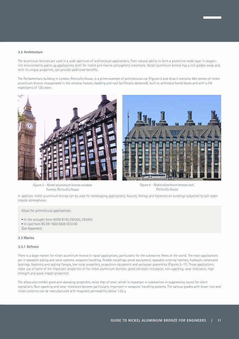
The aluminium bronzes are used in a wide spectrum of architectural applications. Their natural ability to form a protective oxide layer in oxygen-rich environments opens up applications, both for inland and marine atmospheric conditions. Nickel aluminium bronze has a rich golden oxide and, with its unique properties, can provide additional benefits.
The Parliamentary building in London, Portcullis House, is a prime example of architectural use (Figures 3 and 4) as it contains 450 tonnes of nickel aluminium bronze incorporated in the window frames, cladding and roof (artificially darkened), built to withstand bomb blasts and with a life expectancy of 120 years.
In addition, nickel aluminium bronze can be used for landscaping applications, fixtures, fittings and fasteners on buildings subjected to salt-laden coastal atmospheres.
3.3 Marine
3.3.1 Defence
There is a large market for nickel aluminium bronze in naval applications, particularly for the submarine fleets of the world. The main applications are in seawater piping and valve systems, weapons handling, flexible couplings, sonar equipment, seawater external hatches, hydraulic valves and bearings, fasteners and sealing flanges, low noise propellers, propulsion equipment and periscope assemblies (Figures 5–11). These applications make use of some of the important properties of the nickel aluminium bronzes: good corrosion resistance, non-sparking, wear resistance, high strength and good impact properties.
The alloys also exhibit good anti-damping properties, twice that of steel, which is important in submarines in suppressing sound for silent operations. Non-sparking and wear resistance become particularly important in weapons' handling systems. The various grades with lower iron and nickel contents can be manufactured with magnetic permeability below 1.03 µ.
Figure 3 – Nickel aluminium bronze window frames, Portcullis House
Figure 4 – Nickel aluminium bronze roof,Portcullis House
Alloys for architectural applications:
• In the wrought form ASTM B150 C63200, C63000 • In cast form BS EN 1982:2008 CC333G(See Appendix).

12 | GUIDE TO NICKEL ALUMINIUM BRONZE FOR ENGINEERS
Figure 5 - Water end entry valve (Courtesy IMI Truflo)
Figure 6 – Submarine penetrator, machined from forging (Courtesy Copper Alloys Ltd, Stoke-on-Trent, UK)
Figure 7 - Submarine propeller (Courtesy Inoxyda SA, France)
Figure 8 - Piston forging 5000 kg (Courtesy Copper Alloys Ltd, Stoke-on-Trent, UK)
Figure 9 - Ocular box submarine periscope(Courtesy Inoxyda SA, France)
Figure 10 - Submarine acoustic antenna(Courtesy Inoxyda SA, France)

GUIDE TO NICKEL ALUMINIUM BRONZE FOR ENGINEERS | 13
3.3.2 Commercial
Nickel aluminium bronze is one of the main alloys used for ship propellers on commercial vessels and cruise liners. Its high resistance to cavitation, coupled with reasonable cost and the ease of repair when damaged, makes it a leading contender for this application (Figures 12 and 13).
Figure 11 – Adjustable bolted propeller - one of two 33 tonne propellers from the Queen Elizabeth class
aircraft carrier capable of producing 40 MW of thrust(Courtesy Rolls Royce Marine)
Figure 12 - Variable pitched propeller (Courtesy Rolls Royce Marine)
Figure 13 - Fir propeller (Courtesy Inoxyda SA, France)
The main alloys used in marine defence applications are:
• UK Def Stan 02-747 Parts 1-4 (cast)• UK Def Stan 02-833 (wrought)• ASTM B150 C63200(See Appendix).
14 | GUIDE TO NICKEL ALUMINIUM BRONZE FOR ENGINEERS
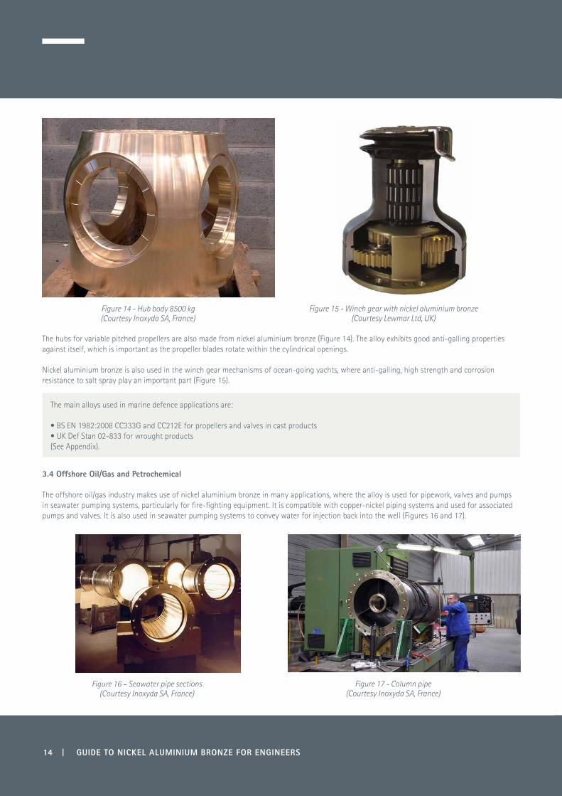
The hubs for variable pitched propellers are also made from nickel aluminium bronze (Figure 14). The alloy exhibits good anti-galling properties against itself, which is important as the propeller blades rotate within the cylindrical openings.
Nickel aluminium bronze is also used in the winch gear mechanisms of ocean-going yachts, where anti-galling, high strength and corrosion resistance to salt spray play an important part (Figure 15).
3.4 Offshore Oil/Gas and Petrochemical
The offshore oil/gas industry makes use of nickel aluminium bronze in many applications, where the alloy is used for pipework, valves and pumps in seawater pumping systems, particularly for fire-fighting equipment. It is compatible with copper-nickel piping systems and used for associated pumps and valves. It is also used in seawater pumping systems to convey water for injection back into the well (Figures 16 and 17).
Figure 14 - Hub body 8500 kg(Courtesy Inoxyda SA, France)
Figure 15 - Winch gear with nickel aluminium bronze (Courtesy Lewmar Ltd, UK)
The main alloys used in marine defence applications are:
• BS EN 1982:2008 CC333G and CC212E for propellers and valves in cast products • UK Def Stan 02-833 for wrought products(See Appendix).
Figure 16 – Seawater pipe sections(Courtesy Inoxyda SA, France)
Figure 17 - Column pipe (Courtesy Inoxyda SA, France)

GUIDE TO NICKEL ALUMINIUM BRONZE FOR ENGINEERS | 15
3.4.1 Bearing Applications within Oil Rig Equipment
Wrought and cast nickel aluminium bronze are used for many bearing applications on oil rigs (Table 5). These are frequently self-lubricating, where bearings are impregnated with specialised compounds. The use of graphite or graphite-rich lubricants or seals should not be used if there is an ingress of seawater since graphite is at the noble end of the galvanic series and can cause preferential corrosion of the nickel aluminium bronze. Nickel aluminium bronze is suitable for slow moving parts where good wear and corrosion resistance is required and in applications where accessibility may be a problem (Figure 18).
Figure 18 – Nickel aluminium bronze bearings with self-lubrication pockets
Table 5 – Bearing Applications within Oil Rig Equipment
Riser pull-in systemsMooring and turret systemsFairleads/chain stoppersWinches/windlassesUniversal jointsJacking and fixation systems
Oil rigs Off-loading terminals including:Loading armsLoading couplings
Pipe-laying equipment Stinger handling system Stinger tower hinge
Pipe handling equipment Pipe couplings
Riser applicationsHang-offs Connectors
Tensioner systems Riser pull-in systems
Drilling equipment and machinery Top drive systemsTube handlingsWellhead systemsDrilling tools
Subsea applicationsAutonomous underwater vehicles (AUVs)Remote operated vehicles (ROVs)Subsea tools

16 | GUIDE TO NICKEL ALUMINIUM BRONZE FOR ENGINEERS
Self-lubricating bearings are also used in the Fairlead Stopper unit and mooring lines. This unit is sometimes suspended from the structure legs and incorporates self-lubricating bearings which connect the ears for attaching the latch housing assembly.
Mud pumps are used both in offshore oil rigs and land-based drilling rigs. Figure 21 illustrates a typical mud pump and Figure 22 shows some of the spare part bearings used in these pumps.
Figure 19 – Self-lubricating pinion bearing used in a jack-up system gearbox
(Courtesy Federal-Mogal Deva GmbH, Germany)
Figure 20 – Jack-up rig units which use additional bearings and bushings in the cranes and mooring winches
as well as the jack-up gearboxes
Figure 21 – Typical mud pump (Courtesy © MHWirth, Germany)
Figure 22 – Bearings used in mud pumps

GUIDE TO NICKEL ALUMINIUM BRONZE FOR ENGINEERS | 17
3.4.2 Communications and Transponders
There are two areas where the corrosion resistance of nickel aluminium bronze is used in communications. The first is acoustic release transponders (Figure 23) and the second, fibre optic electrical connectors (Figure 24). Both applications make use of the alloy’s good corrosion resistance in seawater.
The transponder application allows equipment to be lowered to its operational location, at which point it can be released from the securing cable under water.
Alloy grades typically used for bearings are:
• ASTM B505, C95400, C95500, C95800• BS EN 1982:2008, CC333G, CC334G(See Appendix).
Figure 23 – Transponders(Courtesy EdgeTech, USA)
Figure 24 - Electrical connectors used in Mil Std D38999(Courtesy Amphenol Ltd, UK)
Alloys typically used for connectors and transponders are:
• UK Def Stan 02-833• BS2 B 23• ASTM B150, C63000 and C63200(See Appendix).

18 | GUIDE TO NICKEL ALUMINIUM BRONZE FOR ENGINEERS
3.4.3 Actuator Valves
Actuator valves are an important application, both on land-based pipelines and subsea where oil is being transported.
On land-based applications, pipelines can be situated in isolated areas, as well as in hostile locations. Actuator valves form a vital link in the safety of the oil line, as well as protecting the environment against oil spillage. The valves need to work under extremes of temperature ranging from -50°C in extreme cold conditions, such as those encountered in the Arctic regions, to +50°C at the height of the summer in the Middle East desert areas. They have to withstand the ingress of sand in the desert and be able to work after many years of inactivity. For this reason nickel aluminium bronze is chosen in many of the designs for its corrosion resistance and bearing properties. Nickel aluminium bronze also forms the main component which closes off the valves within the piping system (Figure 25).
Offshore, actuator valves are used on oil rig platforms (Figure 26), where valves are sometimes inaccessible and need to be activated by radio waves.
3.4.4 Oil Tankers
Another important application which makes use of the non-sparking and high corrosion resistance properties is the gas circulating fans in sea-based oil tankers (Figure 27). The fans are used to generate the flow of an inert gas blanket over the oil cargo and to maintain its pressure in order to obviate the danger of explosion or fire. The inert gas used is produced from the exhaust gas from the main engines, auxiliary engines or sometimes from a special generator, by ‘scrubbing’ the exhaust with seawater. The operating conditions can be very corrosive, involving salt-laden water vapour, sulphurous gases and carbon. Both titanium and nickel aluminium bronze are used for this application, with the latter being the lower cost option.
Figure 26 – Actuator valve used on oil rig platform (Courtesy Rotork plc, UK)
Figure 25– Nickel aluminium bronze mechanism in actuator valve, chosen for its corrosion resistance and bearing properties
(Courtesy Rotork plc, UK)
Alloy grades typically used in actuators are:
• BS2 B 23, BS EN 1982:2008, CC338G• ASTM B150, C63000, and C63200(See Appendix).

GUIDE TO NICKEL ALUMINIUM BRONZE FOR ENGINEERS | 19
Figure 27 – Illustration from ‘Inert Gas Protection and Cleaning of Oil Tanker Cargo Tanks’ by Willie Scott from www.brighthubengineering.com
3.5 Desalination and Water Condenser Systems
This industry is an important outlet for nickel aluminium bronze for pumps, valves, water boxes, impellers, condenser tube plates (Figures 28 and 29) and housings. It is used for elevated temperatures up to approximately 325°C in high pressure condenser systems. It can be used for pumping seawater to a recommended level of 4.3 m/sec, which exceeds that tolerated by 90-10 and 70-30 copper-nickel. Although the aluminium bronzes do not have the biofouling resistance of the copper-nickels, they still have a high resistance to marine growth (see Section 6.6).
Alloys typically found in inert gas systems are:
• ASTM B171 C63000• BS EN 1653, CW304G and CW307G(See Appendix).
Figures 28 and 29 - Condenser tube plates (Courtesy Inoxyda SA, France)

20 | GUIDE TO NICKEL ALUMINIUM BRONZE FOR ENGINEERS
Figure 30 – Condenser top cover(Courtesy Inoxyda SA, France)
Figure 31 – Regulator valve 9000 kg(Courtesy Inoxyda SA, France)
Figure 32 - Valve body 2000 mm dia 6000 kg(Courtesy Inoxyda SA, France)
Figure 33 - Pelta Runner (Courtesy Inoxyda SA, France)
There is a range of alloys used in the desalination and water condenser sector:
• For sand castings, the nickel aluminium bronze usually used is CC333G (AB2) • For forgings and bar products BS EN 12420 CW307G and BS EN 12163 CW307G• For plate products used in the heat exchange and desalination industry BS EN 1653 CW307G and ASTM B 171 C63000• For maximum corrosion resistance UK Def Stan 02-833(See Appendix).

GUIDE TO NICKEL ALUMINIUM BRONZE FOR ENGINEERS | 21
4.0 Alloying Elements and Microstructural Phases
There is a direct link between microstructure and properties and if the microstructure is altered by heat treatment, fabrication or composition then the properties will change accordingly.
4.1 Influence of Alloying Elements
4.1.1 Aluminium
Aluminium is the main strengthening element and normally ranges from 8-13% within this family of alloys. At the top end of the range, hardness figures of 30-44 HRC are possible. However, at these very high hardnesses, the ductility is reduced to 1% and these alloys can only be used in wear applications for forming and drawing tooling.
4.1.2 Manganese
Manganese is normally added as a deoxidant but is a major alloy addition to one important alloy, CuMn11Al8Fe3Ni3 (Appendix Tables App5 and App9) which, due to its good fluidity and castability, is used in the marine industry for ships’ propellers. Manganese is a beta phase stabiliser and also has a strengthening effect with 6% manganese being equivalent to 1% aluminium.
4.1.3 Nickel
Nickel is added in quantities ranging from 1-7%. Nickel is soluble in copper at lower levels and is added in conjunction with iron. Its presence improves the corrosion resistance and increases the mechanical strength. It also helps with the erosion resistance in high velocity water flow.
4.1.4 Iron
Iron can refine the structure and gives toughness. It has low solubility at room temperature in these alloys and can provide iron-rich kappa precipitates by controlled heat treatment to strengthen the alloy. It is beneficial for the iron content to be less than that of nickel.
4.1.5 Impurities
This is an important aspect of the specification, particularly those alloys used in military or naval applications where impact toughness is important, and for those alloys involved in welding operations. Low melting point elements such as lead, magnesium and phosphorus, commonly found in copper-based alloys, have a detrimental effect on hot formability, weldability, impact toughness and ductility.
• Lead is normally limited to 0.05% but the preferred limit is 0.01% as it can cause hot shortness in welded structures. A study on castings has indicated that lead and bismuth together caused hot shortness and should be limited to 0.05% bismuth and 0.01% lead when in combination (8).
• Magnesium is sometimes used as a deoxidant prior to adding aluminium and is normally limited to 0.05%. However, even at 0.01% it can
have a harmful effect on ductility if present with lead towards the higher impurity limit (9).
• Phosphorus can cause hot shortness when greater than 0.01%.
4.2 Types of Microstructural Phases
The aluminium bronze and nickel aluminium bronze equilibrium phase diagrams shown in Figures 34 and 35 can appear rather complicated with a number of microstructural phases possible. In the binary system of copper and aluminium, Figure 34, for up to approximately 9% aluminium, the equilibrium metal structure is a single (alpha) phase.

22 | GUIDE TO NICKEL ALUMINIUM BRONZE FOR ENGINEERS
Figure 34 - Binary copper-aluminium phase diagram (10)
Above approximately 8% aluminium, a second phase known as β (beta) appears in the metal structure at high temperatures, which is stronger and harder. However, on slow cooling below 565oC, the β phase becomes unstable and decomposes to a finely divided structure (eutectoid) containing α and another stronger, but less ductile, embrittling phase γ2 (gamma 2). Also γ2 can be attacked preferentially in seawater and is not desirable.
Nickel and iron additions suppress the γ2, as in Figure 35. When both iron and nickel are present at nominally 5%, the structure of 9-10% aluminium alloys is modified and, instead of the formation of γ2, a new phase κ (kappa) is created, which is more beneficial.
Figure 35 - Cu-Al-Ni-Fe phase diagram at 5% each of nickel and iron (10)
4 6 8 10 12 14 16 18
1200
1100
1000
900
800
700
600
500
400
Weight percentage aluminium
Tem
pera
ture
, °C
Liquid
Liquid + βLiquid + α
α
α+ββ
α+γ2
γ2
γ1
β+γ2
β+γ
1
Weight percentage aluminium
Tem
pera
ture
, °C
4 6 8 10 12 14 16
1200
1100
1000
900
800
700
600
500
400
Liquid
α�κ
α�κ�γ2
β�κ
α�β
α�
β�
κ
βα

GUIDE TO NICKEL ALUMINIUM BRONZE FOR ENGINEERS | 23
The nickel aluminium bronzes are similar to quench hardening steels in their structural morphology as they also undergo a martensitic transformation if cooled quickly from elevated temperatures. Figure 36 shows samples which have been polished and etched to reveal their structures and then examined at magnification under a metallurgical microscope.
x100 x500
Figure 36 - CuAl10Ni5Fe4Mn DIN 2.0966 Widmanstätten martensitic structure. Water quenched from 900°C. Etched in acidified ferric chloride solution.
In the quenched condition, the structure consists of α and martensitic β and some primary κ phases. In this condition the material has high strength but very limited ductility and is highly stressed, having been water quenched. This can be improved by a heat treatment called tempering. Tempering of the structure with aluminium >10% is normally conducted whilst the material is still warm to prevent stress cracking.
At the tempering temperature in the region of 500-715°C, the β transforms to α + κ eutectoid (Figure 37) and further secondary κ precipitates from the structure. As time progresses, more of the β is transformed and, in doing so, the ductility increases, as does strength and hardness. This transformation process is used in many of the aerospace specifications due to its hardening effects. The hardening mechanism by the controlled precipitation of the kappa phase is also used to advantage for improving wear resistance in many bearing applications.
By viewing the structure in the unetched condition (Figure 38), the κ phase is more easily observed in its various forms. They have been designated by a numbering system based on the order in which they appear in the microstructure as the temperature falls on cooling. Although there are similarities between them, they can be distinguished by their morphology, location and distribution in the structure:
κI has a rosette form
κII is a spheroidised precipitate at the grain boundary κIII is a lathe-shaped lamellar phase and κIV is a fine precipitate within the grains.
In terms of corrosion resistance, κI, κII and κIV have little effect but κIII can have an influence, particularly if it forms a continuous network. Heat treatments have been developed to transform residual β to α+ κ and modify the κIII into a globular form and, in so doing, optimise the corrosion resistance in seawater. Heat treatment processes, including their effect on microstructure, are explained in more detail in Section 7.0.

24 | GUIDE TO NICKEL ALUMINIUM BRONZE FOR ENGINEERS
α retained β α + κ eutectoid
Figure 37 - Magnification x500 - ASTM B150 C63200 Water quenched from 845°C and tempered at 715°C for 3 hours
CuAl9Ni4Fe4Mn1 grain size average 7 (31.8 µm). Etched in acidified ferric chloride
κI κII κIII κIV
Figure 38 - Magnification x500 Unetched - CuAl9Ni4Fe4Mn1 ASTM B150 C63200Water quenched from 845°C and tempered at 715°C for 3 hours
This figure illustrates the four forms of kappa phase that can be seen in nickel aluminium bronze
Scanning electron microscope examination has enabled specific analysis of each phase type (Figure 39 and Table 6) (16). In general terms, κIII differs as it is nickel-rich based on NiAl precipitates compared to the others which are relatively richer in iron and based on Fe3Al.

GUIDE TO NICKEL ALUMINIUM BRONZE FOR ENGINEERS | 25
Figure 39 – Micrographic phase structure of nickel aluminium bronze - Magnification x500
Table 6 – Energy Dispersive X-Ray Spectroscopy Analysis of the Phases Present in Cast Nickel Aluminium Bronze (16)
Phase Alloy Component (Wt %)
Al Mn Fe Ni Cu
α 7.90 0.20 2.58 2.91 86.41
β 8.51 0.52 2.20 2.58 86.19
κI17.35 1.25 35.69 18.07 27.64
κII19.09 0.93 26.60 26.04 27.34
κIII18.87 0.45 12.86 26.80 41.03
κIV8.12 0.84 42.70 35.32 13.01
β
κIII
κII
κI
κIV
α

26 | GUIDE TO NICKEL ALUMINIUM BRONZE FOR ENGINEERS
5.0 Properties
5.1 Mechanical Strength
The nickel aluminium bronzes offer a wide range of mechanical strength across the family of alloys (Tables 7a-7c). Minimum mechanical properties are given in tables throughout this booklet unless indicated otherwise. Also, for uniformity, yield strength data obtained from various US sources have been relabelled as proof strength. Further information can be found in the Appendix and Copper Development Association publication 82 Aluminium Bronze Alloys Technical Data.
Increased aluminium content can improve strength and this is shown in Table 7a, which compares cast CuAl11Fe4Ni4 and CuAl9Fe4Ni4 alloys with nominally 11% and 9% aluminium respectively. With aluminium contents above 10% very high mechanical properties can be obtained with quench and temper heat treatments, but with lower ductility, and this is also illustrated. These types of alloys are mainly used for bearing applications.
Table 7a - Strengthening Effect of Aluminium and Enhanced Properties from Quench and Temper Hardening
Specification Designation Condition 0.5% Proof Strength
N/mm² (MPa)
Tensile Strength
N/mm² (MPa)
Elongation%
ASTM B505 C95500 CuAl11Fe4Ni4 As cast 290 655 10
Heat treated * 427 758 8
ASTM B505 C95800** CuAl9Fe4Ni4 As cast 276 620 15
* Solution heat treated at 860-890°C 1 hour per inch of section thickness, water or oil quenched and temper annealed 620-660°C for 1 hour per inch of section thickness.
** Alloy C95800 can be temper annealed at 677°C +/- 10°C for 6 hours minimum and rapid cooled, if section permits, to improve corrosion resistance.
Working the materials to refine the grain structure can also increase the mechanical properties, as shown in Table 7b, which compares wrought vs cast CuAl10Fe5Ni5.
Table 7b - Cast vs Hot Worked Mechanical Properties
Specification Designation Condition 0.2% Proof Strength
N/mm² (MPa)
Tensile Strength
N/mm² (MPa)
Elongation%
BS 2B 23 CuAl10Fe5Ni5Extruded and drawn 18-80 mm dia
370 650 12
BS EN 1982 CC333G CuAl10Fe5Ni5 Continuous cast 280 650 13
The high aluminium-containing nickel aluminium bronzes can be heat treated to maximise their hardness and tensile strength, which makes them ideal for bearing applications. Table 7c illustrates this for both cast and wrought alloys.
Table 7c - High Mechanical Properties Achievable for Alloys Used for Aerospace Bearing Applications
Specification Designation Condition 0.2% Proof Strength
N/mm² (MPa)
Tensile Strength
N/mm² (MPa)
Elongation%
HardnessHRC
AMS 4590 * CuAl10.5Fe5Ni5 Extruded and H/T TQ50 25.4-50.8 mm dia 689 931 6 26
AMS 4881 ** CuAl11Fe5Ni5 Continuous cast, ≤50 mm dia 621 860 2 28
* TQ50. Solution heat treat 843-899°C for not less than 2 hours, water quench and temper at 482-538°C for not less than 2 hours and air cool.
** Solution heat treat 871-927°C for not less than 2 hours, water quench and temper at 496-538°C for not less than 2 hours and air cool.

GUIDE TO NICKEL ALUMINIUM BRONZE FOR ENGINEERS | 27
The high manganese aluminium bronzes can have high strength, ductility and impact toughness which can be greater than their cast nickel aluminium bronze counterparts. This is illustrated in the Appendix in Table App10 for standard BS EN 1982:2008 comparing sand cast nickel aluminium bronze CuAl10Fe5Ni5, CC333G, to CuMn11Al8Fe3Ni3, CC212E.
5.2 Low and High Temperature Properties
Unlike some steels, nickel aluminium bronzes do not become embrittled at low temperatures and hence are ideal for cryogenic applications down to -190°C. With decreasing temperature, there is a gradual increase in proof and tensile strength and a fall in ductility and impact toughness, but not to a critical level (Table 8).
At elevated temperatures, above approximately 350°C, the strength starts to decline. Therefore operating temperatures above 325°C are not usually recommended.
Table 8 - Mechanical Properties from Sub Zero to Elevated Temperatures of Alloy CuAl10Ni5Fe3 (11)
Temp oC
0.5% Proof Strength
N/mm² (MPa)
Tensile Strength
N/mm² (MPa)
Elongation %
Reduction in Area
%
Youngs Modulus N/mm² x 103
Impact Charpy V
Notch Joules
Hardness HB
-182 430 886 12 12 130 12.2 235
-59 378 785 24 26 123 17.6 212
-29 384 780 23 23 139 17.6 209
24 369 766 21 21 125 19 200
204 347 709 16 15 107 20 189
316 334 605 10 11 110 11 175
427 157 234 41 46 64 9 101
538 77 94 39 46 48 9 50
5.3 Impact Toughness
The Izod impact toughness of the wrought alloys normally falls within the range 14-27 Joules with the exception of the high aluminium (>10%) materials, which have high strength but low ductility, such as CuAl11Ni6Fe6. The cast alloys are normally much lower at 5-15 Joules.
Charpy V Notch values are shown in Table 8 spanning cryogenic to elevated temperatures.
As with all alloys that encounter shock loading, it is important to avoid sharp notches and stress-raisers such as coarse machining or stamped identification marks.

28 | GUIDE TO NICKEL ALUMINIUM BRONZE FOR ENGINEERS
5.4 Fatigue Strength
Most of the work conducted on fatigue testing of the nickel aluminium bronzes (Tables 9a and 9b) has been carried out on wrought alloys which are used under highly stressed conditions. The general accepted limit under reverse bending conditions for endurance in air at 10 7 cycles is approximately 300-350 N/mm² depending on tensile strength.
Fatigue strength can vary under different operating conditions, as illustrated when immersed in seawater and 3% NaCl in Table 9b and exposed to salt spray in Figure 40. See Section 6.13 for more information on corrosion fatigue data.
Table 9a – Fatigue Strength at Room Temperature of Nickel Aluminium Bronze (12)
Alloy Designation
Form Temper Condition No of Cycles x106
Tensile Strength N/mm² (MPa)
Fatigue Strength N/mm² (MPa)
CuAl9Ni6Fe3 25-50 mm dia Forged In air 20 883 324 (b)
CuAl10Ni5Fe5 50 mm dia Forged In air 30 723 285 (a)
CuAl10Ni5Fe5 Rod Forged In air 56.8 798 347 (c)
CuMn13Al8Fe3Ni3 Not stated Forged In air 100 730 309 (d)
CuAl9Ni5Fe4Mn Not stated As cast In air 100 655 210 (d)
CuAl9Ni5Fe4Mn Not stated Cast H/T In air 100 827 260 (d)
CuAl10Fe5Ni5 Not stated As cast In air 100 551 220 (d)
CuMn11Al8Fe3Ni3 Not stated As cast In air 100 649-727 232-247( d)
CuMn11Al8Fe3Ni3 Not stated As cast In salt spray 100 649-727 131 (d)
a) Rotating bending test (b) Rotating cantilever test (c) Rotating beam test (d) Method not stated
Table 9b - Comparison of Fatigue and Corrosion Fatigue Data for Wrought Nickel Aluminium Bronze (4)
Alloy Composition
Form Tensile Strength
N/mm² (MPa)
No ofCycles
Endurance Limit in Air
N/mm²
Endurance Limit in Seawater or 3% NaCl
N/mm²
CuAl10Fe3Ni5 Not stated 741 10 8 227 139
CuAl9Fe5Ni5 Hot rolled strip756
10 7 309 232
5 x 10 7 278 139
CuAl9.7Fe5.4Ni5 Forged 804 5 x 10 7 305.5 225.5
CuAl10.5Fe5Ni5 Hot rolled strip942
10 7 309 208.5
5 x 10 7 293 154.5
CuAl10.6Fe4.7Ni4.6 As extruded 865 10 7 355 255
CuAl9.7Fe5.3Ni5.1 Rolled rod 33mm dia 833 10 7 340 275
CuAl11Fe4Ni4 Quench 890°C and tempered 620°C
882 5 x 10 7 340 196

GUIDE TO NICKEL ALUMINIUM BRONZE FOR ENGINEERS | 29
Figure 40 - Fatigue curve for cast high manganese aluminium bronze CuMn11Al8Fe3Ni3, which illustrates a reduction in fatigue life when comparing normal air and sea spray conditions (12)
5.5 Creep Strength
In the application of nickel aluminium bronzes for pressure vessels, desalination plants and condenser systems, creep becomes important with elevated operation temperatures in the region of 150-250°C. The design of these plants is normally based on 100,000 operational hours, approximately 12 years (Table 10). Further data is given in Table 11.
Table 10 – Creep Stress Properties of CuAl10Ni5Fe4 CW307G to BS EN 1653:1997
Temperature 1% Creep Stress Duration N/mm² (MPa)
°C 10 x 10³ hours 30 x 10³ hours 50 x 10³ hours 100 x 10³ hours
150 252 242 237 232
160 243 233 228 224
170 236 226 221 216
180 229 219 214 209
190 223 213 208 203
200 218 207 202 198
210 213 202 197 193
220 210 199 193 188
230 207 196 190 185
240 205 194 188 182
250 204 192 186 180
1 10 100 1000
400
350
300
250
200
150
100
Reversals to fracture - 105 reversals
Alte
rnat
ing
stre
ss N
mm
-2
In salt spray
In air
30 | GUIDE TO NICKEL ALUMINIUM BRONZE FOR ENGINEERS
Table 11- Creep Properties for Alloy CuAl9Fe5Ni5 ex UK Def Stan 02-879 Part 1 (3)
13 mm Annealed Plate
Temperature°C
Creep Rate % per 1000 hours
Stress for Designated Creep RateN/mm² (MPa)
250 0.01 123
250 0.1 167
350 0.01 46
350 0.1 86
450 0.01 17
450 0.1 32
550 0.01 3.1
550 0.1 12
5.6 Magnetic Permeability
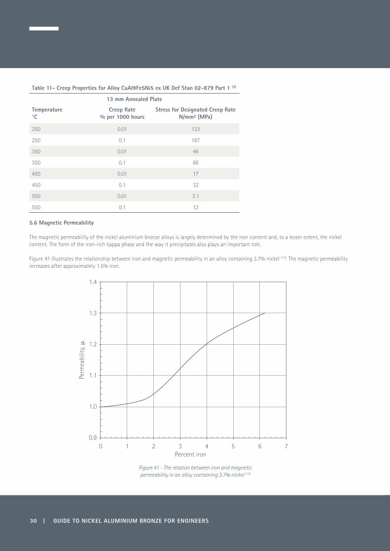
The magnetic permeability of the nickel aluminium bronze alloys is largely determined by the iron content and, to a lesser extent, the nickel content. The form of the iron-rich kappa phase and the way it precipitates also plays an important role.
Figure 41 illustrates the relationship between iron and magnetic permeability in an alloy containing 3.7% nickel (13). The magnetic permeability increases after approximately 1.5% iron.
Figure 41 - The relation between iron and magnetic permeability in an alloy containing 3.7% nickel (13)
Percent iron
Perm
eabi
lity,
�
0 1 2 3 4 5 6 7
1.4
1.3
1.2
1.1
1.0
0.9

GUIDE TO NICKEL ALUMINIUM BRONZE FOR ENGINEERS | 31
Table 12 gives typical µ values for a range of the alloys with various iron and nickel levels. It also shows the influence of tempering on C95500 which can influence the kappa formation and lower the permeability.
Table 12 - Typical Magnetic Permeability Values for Nickel Aluminium Bronze Alloys
Standard Alloy Designation Magnetic Permeability, µ
BS EN 12165 CW308G CuAl11Fe6Ni6 1.75
BS EN 12165 CW307G CuAl10Fe4Ni5 1.5
Def Stan 02-833 CuAl9Fe5Ni5 1.5
ASTM B150 C63000 CuAl10Fe5Ni3 1.4
ASTM B150 C63200* CuAl9Fe4Ni4 1.35
GAM MM 11 CuAl9Fe2Ni3 1.3
ASTM B505 C95500 CuAl11Fe4Ni4 1.32
ASTM B505 C95500* CuAl11Fe4Ni4 1.2
* Quench and tempered
These alloys, however, are not suitable when there is a requirement for a permeability of less than 1.03 although, for very low iron contents, this is possible. The German specification WL 2.0967 for alloy CuAl9Ni7Fe, the composition of which is given in Table 13, suggests a heat treatment at 680-820°C for 60-120 minutes and air cooling, which also helps to lower the relative magnetic permeability to <1.03 µ.
Table 13 - WL 2.0967 Alloy Composition - Relative Magnetic Permeability ≤ 1.03µ
Cu %
Al %
Ni %
Fe %
Mn %
Rem 9.0-9.5 6.7-7.3 0.9-1.2 0.8-1.2
In comparison, the high manganese-aluminium-iron-nickel alloys such as CuMn11Al8Fe3Ni3 (formerly known as CMA1), CuMn13Al9Fe3Ni3 (formerly known as CMA2), and CuMn11Al8Fe3Ni3 to ASTM B148 C95700 operate under a different system which is an atomic disorder/order mechanism in their structure at slow cooling rates. Their magnetic permeability increases considerably below 500°C, particularly with slow cooling rates. The magnetic permeability can vary between 2-10 µ and, in extreme cases with very slow cooled large castings, it can be as high as 15. However, the atomic reordering can be suppressed by water quenching from above 500°C and the magnetic permeability reduced to <1.03 µ.

32 | GUIDE TO NICKEL ALUMINIUM BRONZE FOR ENGINEERS
6.0 Corrosion Resistance
The corrosion mechanisms described are mainly based on data and experience in seawater but nickel aluminium bronze also has good corrosion resistance in many chemical environments.
6.1 Protective Surface Film
Nickel aluminium bronze relies on the formation of a thin adherent copper/aluminium-rich oxide film of Cu2O and Al2O3, which is self-repairing - even in media containing low oxygen levels. The oxide layer also contains iron and nickel oxides which tend to form under longer exposure and, the greater the concentration of oxygen, the more protective is the film (5).
It is vitally important in the commissioning of equipment, particularly in seawater applications, that the system is flushed through with clean aerated seawater for several hours to assist in building up the protective layer and this is important for long-term corrosion resistance. On occasion, new marine vessels in dock are flushed through with contaminated water and this has proved to be problematic if the water contains high sulphide levels.
The protection against corrosion given by the oxide film can be summarised by the following properties:
• It adheres firmly to the surface of the substrate• It has an initial thickness of ~0.001 mm and has resistance to liquid penetration• It has the ability to self-repair in non-deaerated conditions• It has good resistance to liquid flow velocity below the recommended value of 4.3 m/sec. At lower velocities the film thickness will tend to
increase with time, reaching a steady corrosion rate of ~0.05 mm per year• The hardness of the alumina content of the film (Al
2O3) creates higher resistance to erosion and abrasion.
Also, the availability and mobility of copper ions at the surface provide good resistance to biofouling as they hinder the adherence, colonisation and growth of marine and micro-organisms. The alloys also perform well in air and salt-laden atmospheres and can be used in many architectural applications where their rich golden yellow colour is pleasing to the eye.
6.1.1 Oxidation at Elevated Temperatures
Nickel aluminium bronze can be used up to temperatures of 325°C without deterioration in properties and, under these conditions, the oxide layer formed in air will marginally increase in thickness and darken in appearance.
6.2 Pitting
Pitting can occur through a process termed differential aeration due to localised damage of the oxide film or internal defects uncovered by machining or fettling. Examples of defects are oxide inclusions, slag inclusions, porosity and foreign deposits. Pitting can also be caused by attack of less noble phases within the structure. Such attack is more likely to occur in an ‘as cast’ structure than wrought products where the internal integrity of the metal is more uniform and finer grained through hot working and heat treatment. Pitting corrosion in all metals is an important consideration, particularly in thin-walled components such as pipework where, because of the localised nature of the corrosion, perforation can occur.
Nickel aluminium bronze has good resistance to pitting corrosion, particularly in the wrought condition. Cathodic protection, e.g. coupling to a less noble alloy, can help reduce the risk of this type of corrosion but has the disadvantage of suppressing the natural ability of this alloy to resist marine growths.
Cast alloy under EN 1982:2008 (Appendix, Table App9) CuAl10Ni3Fe2 for seawater applications, recommends the following aluminium content for maximum corrosion resistance (as such, includes pitting resistance), by optimising the structure against selective phase attack:
Al% <8.2 + 0.5 Ni%
6.3 Crevice Corrosion
A crevice is a shielded area where two component parts or foreign objects are in close contact with each other, allowing a thin film of liquid to penetrate between the two. It can be a thin film of water between flanges or fasteners, or a shielded area which has resulted from a marine growth or some other form of non-organic deposit.

GUIDE TO NICKEL ALUMINIUM BRONZE FOR ENGINEERS | 33
Crevice corrosion in metals is a very complex mechanism and influenced by electrochemical reactions and crevice geometry. The shielded area is starved of oxygen and differential aeration takes place which creates a potential difference between the oxygen-deprived area and the external surface which may be richer in oxygen.
Nickel aluminium bronze which is not cathodically protected or connected to galvanically less noble alloys can be susceptible to crevice corrosion. The crevice corrosion mechanism which occurs is different to that found in stainless steels as it is a type of selective phase corrosion and is described in Section 6.4. As a function of the structure, it can be minimised by:
• heat treatment (see Sections 7.4 and 7.5)• refining the structure by hot working• allowing a protective surface film to form in early service by correct exposure to the corrosive environment.
6.4 Selective Phase Corrosion
The broad mechanism of selective phase corrosion (15) (sometimes called dealuminification) has been known for many years in binary aluminium bronzes. The most corrosion prone phase for those alloys is γ2. Less rich in aluminium, but still significantly corrodible, is the martensitic β phase. If good corrosion resistance is required, this is avoided by suitable control of composition and cooling rate or corrected by heat treatment. With nickel aluminium bronze, α+κIII eutectic phase is formed which is less corrodible than γ2 and martensitic β. However, it can still be liable to selective phase attack under crevice corrosion conditions unless corrective measures are taken.
Selective phase corrosion is more commonly seen in castings, where the grain size is larger and unrefined, and also there is a higher presence of segregation, inclusions and phases which exist in an unfavourable morphology. In the wrought form most of these problems can be significantly reduced, due to a fine grain structure, consolidation of porosity and a more even distribution of phases in the least corrosive form. With the advent of modern complex Computer Numerical Control (CNC), 3 and 5 axis machining centres and the recycling of swarf, many components previously cast can now be manufactured economically by this method.
Studies with cast nickel aluminium bronze in seawater (14,17) have explained the mechanism by observing that phases within the structure can change polarity with time. The copper-rich α phase is found to be initially anodic to the aluminium-iron-nickel-rich κIII phase and corrodes preferentially for a time at a low rate (Figure 42).
Figure 42 – This shows a low rate of corrosion of the copper-rich α within the α + κIII eutectoid (17)
As the hydrogen level increases in the crevice, the pH of the water drops. Over a five-month period, the crevice was measured as changing from being slightly alkaline at a pH of 8.2 to a markedly acidic pH of 3. At this stage there is a switch in the cathodic and anodic phases within the structure and the κ III becomes more anodic and starts to corrode at a faster rate (Figure 43). This is often accompanied by the deposit of metallic copper in the corrosion zone, which masks the corrosion damage. Detection can become difficult with the re-deposition of copper which can appear on the surface as discolouration but conceal a sponge-like structure underneath.

34 | GUIDE TO NICKEL ALUMINIUM BRONZE FOR ENGINEERS
Figure 43 – Corrosion attack of κIII
(17). A micro-environment is created below the deposit and causes a drift towards the acidic range, i.e. below pH 4.0, which alters the electrochemical equilibrium. The κIII phase then becomes anodic to the α phase and corrodes preferentially.
However, if the nickel aluminium bronze comes into contact with oxygen-containing water in its initial immersion, then a resistant oxide film is produced which gives improved protection against this type of attack. Studies have found the formation of the protective oxide layer provides corrosion protection, reducing the rate by a factor of 20-30. The protection has been attributed to both a decrease of the anodic dissolution reaction which reduces the ionic transport across the oxide layer, as well as a decrease in the rate of the cathodic reaction in the oxide layer (16).
The corrosion resistance can also be improved through heat treatment, as described in later sections. The specific heat treatment used can change the morphology of the κIII into a more globular form (Figure 44).
Figure 44 - Nickel aluminium bronze with globular κ III
(Courtesy BA Systems, UK)6.5 Galvanic Corrosion
When a metal is immersed in a conducting liquid, such as seawater, it adopts an electrode potential which is usually measured against a standard reference electrode, such as the saturated calomel electrode (SCE), as shown in Figure 45. When two metals with different potentials are connected together, a current flows to equalise the potentials. This current will cause additional corrosion of the more electronegative metal and less corrosion
GUIDE TO NICKEL ALUMINIUM BRONZE FOR ENGINEERS | 35
of the more electropositive metal. This additional corrosion is called galvanic or bimetallic corrosion. The greater the current density, the greater is the galvanic corrosion of the electronegative metal. Factors which increase the current are more important than the actual potential difference, and galvanic corrosion can occur with metals with a potential difference of only 50 mV if other factors are adverse.
The two most important factors are area ratio and cathodic efficiency. If the area ratio of the cathode (more electropositive metal) is large and the anode (electronegative metal) is small, then the current density on the anodic metal will be large and consequently corrosion will be severe. Reversing the area ratio can drastically reduce the risk of galvanic corrosion, i.e. large anode and small cathode.
The electrochemical reaction on the cathode is usually the reduction of dissolved oxygen and, the more efficient this reaction is, the greater will be the current in the galvanic couple, and therefore the corrosion. This is a function of the metal composition and the nature of any films on the metal surface.
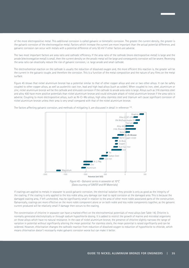
Figure 45 shows that nickel aluminium bronze has a potential similar to that of other copper alloys and one or two other alloys. It can be safely coupled to other copper alloys, as well as austenitic cast iron, lead and high lead alloys (such as solder). When coupled to iron, steel, aluminium or zinc, nickel aluminium bronze will be the cathode and stimulate corrosion if the cathode to anode area ratio is large. Alloys such as 316 stainless steel and alloy 400 have more positive potentials than nickel aluminium bronze and could stimulate attack of nickel aluminium bronze if the area ratio is adverse. Coupling to more electropositive alloys, such as Ni-Cr-Mo alloys, high alloy stainless steel and titanium will cause significant corrosion of nickel aluminium bronze unless their area is very small compared with that of the nickel aluminium bronze.
The factors affecting galvanic corrosion, and methods of mitigating it, are discussed in detail in reference (18).
Figure 45 - Galvanic series in seawater at 10°C(Data courtesy of SINTEF and RF Materials)
If coatings are applied to metals in seawater to avoid galvanic corrosion, the electrical isolation they provide is only as good as the integrity of the coating. If the coating is only applied to the less noble alloy, any damage can lead to rapid corrosion at the damaged area. This is because the damaged coating area, if left unchecked, may be significantly small in relation to the area of other more noble associated parts of the construction. Galvanically, coatings are more effective on the more noble component alone or on both noble and less noble components together, as the galvanic current produced will be relatively small if damage then occurs to the coating.
The concentration of chlorine in seawater can have a marked effect on the electrochemical potentials of most alloys (see Table 14). Chlorine is normally generated electrolytically or through sodium hypochlorite dosing. It is added to restrict the growth of marine and microbial organisms on those alloys which have no natural resistance. In the case of nickel aluminium bronze, the presence of chlorine slightly narrows the range of variation in potential without significantly altering the mean potential. For stainless steels, the mean potential is raised significantly and can be widened. However, chlorination changes the cathodic reaction from reduction of dissolved oxygen to reduction of hypochlorite to chloride, which means chlorination doesn’t necessarily make galvanic corrosion worse but can make it better.
-2000 -1500 -1000 -500 0 500
MagnesiumAluminium
ZincAl-2.7Mg
Cast IronCarbon Steel
TinLead
Aust Cast IronCopperAl-Brass90/10 Copper-nickel
Ni-Al-BronzeNickel
316L (Passive)Alloy 400
Titanium6% Mo/Superduplex SS
Alloy 625/C-276Graphite
Potential (mV SCE)

36 | GUIDE TO NICKEL ALUMINIUM BRONZE FOR ENGINEERS
Table 14 - Effect of Chlorine Additions on the Electrochemical Potential of Certain Materials in Seawater at Room Temperature (10)
Alloy Electrochemical Potential at Room Temperature mV (SCE)
In Natural Seawater In Chlorinated Seawater
Nickel aluminium bronze -260 to -100 -250 to -50
Copper-nickel -250 to -100 -100 to 0
Stainless steel (active) -300 to 0 -100 to +150
Stainless steel (passive) +250 to +350 +500 to +700
Alloy 400 (65/35 NiCu) -150 to +200 -150 to 0
Alloy 625 (high strength nickel alloy) +160 to +250 +290 to +500
6.6 Biofouling
Nickel aluminium bronze has a high resistance to biofouling, although not quite as good as 90-10 copper-nickel, which is due to the higher level of copper in the latter.
Biofouling in the form of macrofouling can have a major impact on seawater structures with regard to restriction of water flow and additional weight increase. A section of a multi-alloy corrosion rack containing tensile specimens immersed in natural seawater for 22 months is illustrated in Figure 46. Due to biofouling, the weight of the rack doubled after only 10 months. The specimens on the left side of the photograph and three on the near right which show high resistance to macrofouling are all copper-based and the marine growths that are visible are attached to the frame and not to the specimens. The specimens in the middle and at the far right which are completely covered in seaweed and sea squirts are duplex/superduplex/superaustenitic stainless steels, nickel alloys, titanium alloys and type 300 stainless steels.
1 CuAl9Ni5Fe5 2 CuNi15Mn5AlFe 3 CuNi30Cr2 4 CuNi14Al3Fe 5 CuNi3Si 6 CuNi30 7 CuNi15Sn8 8 CuNi14Al3Fe 9 Ni-Cu 40010 Ni-Cu K500 11 Alloy 625 12 Alloy 718 13 Alloy 825 14 6%Mo St.St. 15 Superduplex 16 Superduplex 17 Superduplex 18 Duplex 19 316L 20 304L 21 17-4 PH 22 Ti Gr. 2 23 Ti Gr. 5 24 CuNi15Mn5AlFe 25 CuAl9Ni5Fe4Mn 26 CuAl10Ni5Fe4 27 316 28 321
Figure 46 – Multi-alloy corrosion rack after 22 months immersion in seawater, Levington, UK (Courtesy Copper Alloys Ltd, Stoke-on-Trent, UK)
1 2 3 4 5 6 7 8 9 10 11 12 13 14 15 16 17 18 19 20 21 22 23 24 25 26 27 28

GUIDE TO NICKEL ALUMINIUM BRONZE FOR ENGINEERS | 37
In practice, many macrofouling species, including zebra mussels, find aluminium bronze distasteful, so they tend to avoid such structures (19).The growth rate of marine organisms is very complex and dependent on geographical region, season, salinity, pollution levels, depth of water, temperature and other factors. However, the effectiveness of nickel aluminium bronze to resist macrofouling is very much dependent on allowing its free exposure to oxygen-containing seawater. If free exposure is restricted by applied cathodic protection, or connection to adjacent less noble components or structures, the natural equilibrium between copper in the protective film and the seawater will be compromised and higher levels of biofouling can be encountered on the bronze.
Marine biofilms (slimes) and sludges can also have an impact on corrosion resistance of many alloys, including those of copper. The biological film contributes to an alteration of surface energy and the electrochemical behaviour of metals is modified in the presence of metabolic products. The region beneath the film can become anaerobic, leading to the establishment of cells with differential aeration, and the development of anaerobic species such as sulphate-reducing bacteria can occur. The outward movement of metabolic products is impeded, resulting in accumulation of these and this leads to the establishment of concentration cells. Furthermore, a single organism may exert an influence on corrosion reactions by agents produced during its lifetime, or by products of decay after its death. Therefore, prolonged stagnant conditions where sulphate-reducing bacteria can colonise, or where putrefaction can lead to formation of sulphides and ammonia, are to be avoided with nickel aluminium bronze and other copper alloys.
6.7 Electrical Leakage (Stray Current) Corrosion
Accelerated or unexplained high corrosion rates in a component, if coupled directly or indirectly with electrical equipment, can sometimes be caused by electrical leakage - also known as stray current corrosion. This can be severe with galvanic couplings, particularly if nickel aluminium bronze is coupled to a more noble metal which has a higher surface area.
Electrical leakage can arise from a number of causes - faults in the equipment, poor design and poor earthing of equipment through lack of experience, with no knowledge as to the consequences. This type of problem is frequently seen with ship or boat propellers, where there is electrical discharge via the propeller shaft and no insulation between the shaft and propeller. The nickel aluminium bronze propeller could be connected to a stainless or super duplex stainless with a higher nobility, in which case the bronze propeller may corrode at a much higher rate. This situation can also occur with submerged freshwater or seawater pumps.
Electrical discharge can also occur with incorrectly positioned impressed cathodic protection equipment. It is possible for an electrical discharge into water to occur at a set point on the component and then to re-enter at another point. Electrical leakage corrosion is not limited to aluminium bronze but can occur with any metal system. The discharge could be AC or DC and, the higher the voltage, generally the higher the corrosion rate. With nickel aluminium bronze, the form of attack is normally selective phase corrosion.
The problem can be prevented by correct design, maintenance of electrical equipment on a regular basis and using specific earthing points which will not create unexpected discharges.
6.8 Sulphide Pollution
As explained in an earlier section, the corrosion resistance of nickel aluminium bronze is reliant on a thin semi-impervious protective passive oxide film (20). This is also the case with many other alloy systems, including the stainless steels.
It has been known for many years that the breakdown of this protective film by sulphide-induced attack can lead to increased corrosion rates. This can occur in polluted waters or in piping systems where stagnant water collects. Problems have been encountered with propellers and seawater pumps due to a synergistic effect which develops between sulphides and high flow velocities in polluted conditions.
The ability to repassivate (i.e reform the protective film) is an important aspect of controlling the corrosion behaviour. Whilst protective layers formed in unpolluted seawater are known to be self-healing, repassivation after sulphide exposure is not always possible if the exposure has been excessive. The presence of sulphides prevents the formation of hydrous oxides of copper and aluminium, which would normally repassify the exposed area. The use of nickel aluminium bronze is not recommended in sulphide-polluted waters, or under conditions where sulphide-generating bacteria (SGB) can become active.

38 | GUIDE TO NICKEL ALUMINIUM BRONZE FOR ENGINEERS
6.9 Comparative Corrosion Resistance of Various Copper-based Alloys Used in Seawater Applications
Table 15 – Seawater Corrosion Resistance (Corrosion Rates Taken from Def Stan 02-879 Part 1 Issue 1 Amendment 2)
Material Corrosion Resistance Notes
70/30 Copper-nickel Good in atmospheric and immersion conditions
General corrosion <0.025 mm/year
Pitting corrosion <0.13 mm/year
High resistance to stress corrosion cracking
Good resistance to biofouling
Limits on acceptable seawater velocity: 1.0-4.6 m/s
90/10 Copper-nickel Good in atmospheric and immersion conditions
General corrosion <0.025 mm/year
Pitting corrosion <0.13 mm/year
High resistance to stress corrosion cracking
Biofouling resistance better than 70/30 copper-nickel
Limits on acceptable seawater velocity: 1.0-3.7 m/s
Aluminium silicon bronze Good in atmospheric and immersion conditions
General corrosion <0.025-0.05 mm/year
Pitting corrosion <0.5 mm/year
Resistance to impingement attack/erosion corrosion at seawater velocities <2.6 m/s
High resistance to stress corrosion cracking
Resistant to de-alloying and selective phase corrosion
Partially resistant to biofouling
Aluminium-nickel-silicon-bronze
Good in marine atmospheric conditions
General corrosion <0.05 mm/year
Pitting corrosion <0.3 mm/year
Velocity limitation in seawater
High resistance to stress corrosion cracking when correctly heat treated
Good resistance to biofouling
Limits on acceptable seawater velocity: <1.6 m/s
Nickel aluminium bronze Good in atmospheric and immersion conditions
General corrosion <0.025-0.05 mm/year
Pitting corrosion resistance good, particularly with attention to correct alloying and heat treatment
High resistance to impingement attack/erosion corrosion at a seawater velocity of up to 4.3 m/s
High resistance to ammonia stress corrosion cracking and immune to chloride stress cracking
Heat treated material high resistance to de-alloying and selective phase corrosion
Good resistance to biofouling
The copper alloys listed in Table 15 have high corrosion resistance but are not immune to corrosion. All copper alloys are vulnerable to some extent to accelerated corrosion in the presence of sulphides in the service environment, either due to water pollution or the presence of sulphide-generating bacteria (SGB). It is very important that, during commissioning or at start up, flowing clean seawater is used in order to ensure that the initial surface films are formed (see Section 6.1).
Maximum flow rates for design purposes within the ranges given can be influenced by factors such as tube/pipe diameter, bend radius and presence of entrained sand.
The presence of ammonia can cause stress corrosion cracking in copper alloys. The alloys covered by Table 15 are highly resistant but may not be immune to stress corrosion attack under conditions of high stress and high ammonia concentrations.

GUIDE TO NICKEL ALUMINIUM BRONZE FOR ENGINEERS | 39
6.10 Erosion Corrosion
When metals are in contact with fast flowing liquids such as seawater, shear stresses can be generated which damage the protective surface films. Copper alloys can be sensitive to this and the effect can become particularly severe if there is a high degree of turbulence or the liquid contains abrasive particles such as sand.
If flow rates are intermittent and oxygen is present, then in most cases the protective film has time to repair itself. However, if high or turbulent flow rates are persistent or continuous, the protective film is unable to self-repair and local attack can take place in the most vulnerable areas. This type of attack is known as erosion corrosion or impingement attack.
Copper alloys are known to be subject to erosion corrosion when a particular flow rate is exceeded for the set of conditions experienced and this is called the breakaway velocity. The breakaway velocity varies with the type of alloy but nickel aluminium bronze is one of the most resistant copper alloys to this phenomenon. It is therefore used in pumps and valves and remains one of the leading alloys for ship propellers. For pipework systems and valves it is important to stay within recommended maximum system flow rates, which for nickel aluminium bronze is generally ~4.3 m/s.
Research (21) has found that the average erosion corrosion rate of nickel aluminium bronze in fresh unfiltered seawater increased with velocity over the range 7.6-30 m/s. The minimum rate was 0.5 mm/yr at the low end of the velocity range and 0.76 mm/yr at the top end.
When calculating the velocity in a centrifugal pump, it is common to calculate the rotation speed of the outer edge of the impeller and quote this as the maximum flow velocity. However, this gives far too high a velocity than actually occurs in service. This is because the water in this region is also moving, although not as fast as the impeller. A more reliable way to calculate the water velocity seen by the pump materials is to recognise that most impellers have vanes that follow a logarithmic spiral (or close to it). The properties of this curve are that the flow velocity between the vanes is approximately constant because, as the cross-sectional area between the vanes increases, the water is accelerating. Hence, the maximum water velocity can be calculated from the liquid flow from the impeller and the cross-sectional area of the impeller at the circumference. In many water pumps this velocity is 4 to 5 m/s and explains why nickel aluminium bronze works so well in this application when it would be thought not to at the 10–20 m/s velocity calculated from the rotation speed of the impeller circumference (22).
6.11 Cavitation
When liquid flows quickly over a metal surface, rapid changes in pressure can arise. This can occur due to surface defects in the metal, changes in geometry profile or poor design from weldments or joints. Small water vapour bubbles are formed from the turbulence at low pressure points and these tend to migrate to higher pressure areas where they can collapse violently on the surface of the component.
This phenomenon leads to cavitation damage which is seen more frequently in propellers, impellers and turbines where the blade geometry is complex and water flow can be turbulent.
Damage is often seen at a distance from the original source of the bubbles and hence diagnosis of the problem is sometimes difficult unless observed by the trained eye. For example, a low pressure point can exist near the hub of a propeller and the bubbles can travel along the blade and implode a third of the way from the centre. The stresses created can mechanically remove the protective oxide film of alloy systems and can also cause fatigue of the surface, creating micro-cracking which can eventually tear metal particles from the surface.
The soundness of the metal is also of prime importance as oxides or microporosity under the surface can lead to far greater deterioration due to collapse of cavities.
Figure 47 (23) gives good insight into the resistance to cavitation with changes in composition of aluminium bronzes using a vortex generator. Pure copper was used as a reference and it was concluded that the complex nickel aluminium bronzes were more resistant to cavitation than the duplex aluminium bronze alloys shown.

40 | GUIDE TO NICKEL ALUMINIUM BRONZE FOR ENGINEERS
Figure 47 – Cavitation resistance of various aluminium bronzes with exposure time, using copper as a reference (23)
Tables 16 and 17 illustrate the cavitation erosion properties of nickel aluminium bronze in fresh water and 3% NaCl.
Table 16 - Cavitation Erosion Rates in Fresh Water (10, 24)
Material Cavitation Erosion Rate mm³ h-1
Nickel aluminium bronze, CuAl10Fe5Ni5 0.6
Austenitic stainless steel 316 1.7
Ni-resist cast iron 4.4
Table 17 - Cavitation Erosion in 3% NaCl Solution (25)
Material Depth of Attack
CuAl10Fe3Ni5 <0.025 mm in 7 hours
Austenitic stainless steel 321 0.305 mm in 7 hours
In Table 17, the material was vibrated at 20 kHz at an amplitude of +/-0.025 mm and illustrates the superior cavitation resistance of nickel aluminium bronze against a type 300 series stainless steel.
6.12 Stress Corrosion Cracking
Stress corrosion cracking (SCC) occurs when components contain high levels of internal stress through cold working or welding or when they are subjected to stresses beyond their design levels by exceptional loads or excessive torque in the case of fasteners. For aluminium bronze this can occur in the presence of moist sulphur dioxide, nitrites (26), ammonia and ammonia compounds. However, unlike stainless steels, they do not suffer from chloride SCC, even at high temperatures. The single phase aluminium bronzes can suffer from stress corrosion cracking but the complex nickel aluminium bronzes have high resistance. With copper-based alloys used under these conditions, however, it is always advisable to stress relieve components (see Section 7.0 Heat Treatment).
Time of exposure, hours
Loss
of m
ass,
mg
0 50 100 150 200 250 300 350 400
20
18
16
14
12
10
8
6
4
2
0
0.60 mg h-1
0.38 mg h-1 0.11 mg h-10.047 mg h-1
CuCuAl2
CuAl6
CuAl9
CuAl9Ni3Fe2
0.022 mg h-1
0.014 mg h-1
CuAl9Ni5Fe4

GUIDE TO NICKEL ALUMINIUM BRONZE FOR ENGINEERS | 41
6.13 Corrosion Fatigue
Corrosion fatigue strength is an important consideration in the choice of cast and wrought alloys used for propellers, pumps, piping and heat exchangers used in marine applications. These applications can involve oil exploration and subsea vessels which can be subjected to low and high cycle fatigue during operation.
In a corrosive environment, the stress levels and cycle time to failure can be much less than those encountered in air. The relative contributions to the failure mechanism are thus termed corrosion fatigue. Nickel aluminium bronze shows particularly good resistance to both high and low frequency cyclic loading conditions, which is also aided by its inherent corrosion resistance. The combination provides good corrosion fatigue properties.
Cathodic protection helps in reducing the tendency to corrosion fatigue (27) compared to fatigue results in air and salt solution (see Figure 48). Also, research work indicates that cycle frequency has an impact upon fatigue properties, as illustrated in Figure 49 where, for a given cycle stress, the frequency of 2 cps has a lower number of cycles to failure than the higher frequency of 20 cps when tested in 0.5% NaCl (27).
Figure 48 - Effect of applied cathodic current on fatigue resistance of cast CuAl9Ni5Fe4Mn1 C95800 as f (+/-σ) in 0.5% NaCl at 20 Hz at room temperature
Figure 49 - Effect of frequency on corrosion fatigue resistance of cast CuAl9Ni5Fe4Mn1 C95800 in 0.5% NaCl at 20 Hz at room temperature
300290280270260250240230220210200190
43.542.140.639.237.736.334.833.431.930.529.027.6
105 106 107 108
Nf Cycles
KSICy
clic
str
ess,
MN
/m2
Solution
Air
Cathodic protection(1400 � amps/cm2)
300290280270260250240230220210200190
43.542.140.639.237.736.334.833.431.930.529.027.6
105 106 107 108
Nf Cycles
KSICy
clic
str
ess,
MN
/m2
20 cps2 cps

42 | GUIDE TO NICKEL ALUMINIUM BRONZE FOR ENGINEERS
Figure 50 is taken from reference (28). It represents results of corrosion fatigue carried out in seawater at 32°C at various strain rates. The test employed flat specimens strained by bending about a zero strain mean position.
Figure 50 – Fatigue resistance of nickel aluminium bronze in seawater at 32°C, under varying strain rates
Table 18 gives information on corrosion fatigue for marine propellers, rating nickel aluminium bronze against other alloys used for this application.
Table 18 - Corrosion Fatigue Properties of Marine Propeller Alloys (29)
Alloy Time days
Seawater or 3% NaCl
Corrosion Fatigue Strength 108 cycles
Nmm-2 (MPa)
Nickel aluminium bronze CuAl10Fe5Ni5
23* 3% NaCI +108
35 3% NaCI +122
50 Seawater +87
Manganese aluminium bronze CuMn13Al8Fe3Ni3
23* 3% NaCI +91
35 3% NaCI +89
50 Seawater +62
High tensile brass 23* 3% NaCI +62
35 3% NaCI +74
50 Seawater +42
Spheroidal graphite cast iron (ferritic) 23 3% NaCI +46
Spheroidal graphite cast iron (austenitic) 23 3% NaCI +46
13% Cr stainless steel 23 3% NaCI +54
19/11 Austenitic stainless steel 50 Seawater +45
* Indicates samples cut from propellers. All other results were from cast test pieces
Life, hours1 10 100 1000 10 000 10 0000 1 000 000
10 000
1000
100
10
1
Freq
uenc
y, cy
cles
10h
-1
Life, days1 10 100
Life, years1 10 100
Strain range % 1.0 0.8 0.5 0.4

GUIDE TO NICKEL ALUMINIUM BRONZE FOR ENGINEERS | 43
6.14 Comparison in Seawater with Other Alloy Groups
In summary, Table 19 illustrates the corrosion resistance in seawater of nickel aluminium bronze against that of other competing alloy systems by means of arbitrary corrosion resistance ratings, estimated out of ten for each type of condition.
Table 19 - Comparison of Corrosion Properties of Nickel Aluminium Bronze in Seawater with those of Competing Alloys (30)
Category Corrosion Condition
Nickel Aluminium
Bronze
Duplex Stainless
Super Duplex
Stainless
Type 316 Stainless
Super Austenitic Stainless
Ni-Resist D2-W
a General 9 10 10 10 10 8
b Pitting 10 6 10 4 10 10
c Crevice 9 4 8 3 8 10
d Erosion 8 10 10 10 10 6
e Cavitation 8 8 9 7 8 4
f Stress 10 10 10 7 10 5
g Fatigue 9 9 9 6 6 6
h Sulphide polluted 1 5 9 6 6 6
In the above conditions 10 ranks the highest corrosion resistance
A = a+b+c 28 20 28 17 28 28
B = a+b+c+f+g 46 43 48 34 44 33
C = a+b+d+e 35 34 39 31 38 28
D = b+d+e+h 27 29 38 27 34 26
Service Conditions:
Condition A: Static condition or low velocity water flow, exposed to general corrosion, to shielded areas (crevice corrosion), to local surface damage (pitting), but to no significant pollution e.g. valve parts, offshore vertical fire pumps etc.
Condition B: Rotating or moving parts, flow velocity less than 4.3 ms-¹, exposed to general corrosion, to little or no abrasive particles, to local surface damage (pitting), to cavitation, to fluctuating stress, but no significant pollution e.g. propellers and some turbines.
Condition C: Fast rotating parts, flow velocity in excess of 4.3 ms-¹, exposed to general corrosion, to abrasive particles, to local surface damage, to cavitation but no significant pollution e.g. some pump impellers.
Condition D: Rotating and moving parts, exposed to substantial sulphide pollution and to cavitation, e.g. pump impellers in sulphide polluted locations.
Nickel aluminium bronze is a good choice for conditions A and B but is not suited to conditions C and D.
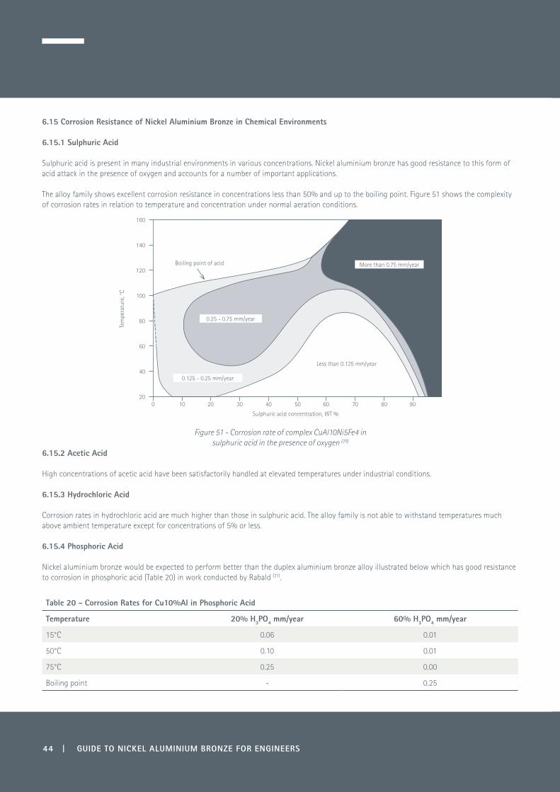
44 | GUIDE TO NICKEL ALUMINIUM BRONZE FOR ENGINEERS
6.15 Corrosion Resistance of Nickel Aluminium Bronze in Chemical Environments
6.15.1 Sulphuric Acid
Sulphuric acid is present in many industrial environments in various concentrations. Nickel aluminium bronze has good resistance to this form of acid attack in the presence of oxygen and accounts for a number of important applications. The alloy family shows excellent corrosion resistance in concentrations less than 50% and up to the boiling point. Figure 51 shows the complexity of corrosion rates in relation to temperature and concentration under normal aeration conditions.
Figure 51 - Corrosion rate of complex CuAl10Ni5Fe4 in sulphuric acid in the presence of oxygen (29)
6.15.2 Acetic Acid
High concentrations of acetic acid have been satisfactorily handled at elevated temperatures under industrial conditions.
6.15.3 Hydrochloric Acid
Corrosion rates in hydrochloric acid are much higher than those in sulphuric acid. The alloy family is not able to withstand temperatures much above ambient temperature except for concentrations of 5% or less.
6.15.4 Phosphoric Acid
Nickel aluminium bronze would be expected to perform better than the duplex aluminium bronze alloy illustrated below which has good resistance to corrosion in phosphoric acid (Table 20) in work conducted by Rabald (31).
Table 20 - Corrosion Rates for Cu10%Al in Phosphoric Acid
Temperature 20% H3PO4 mm/year 60% H3PO4 mm/year
15°C 0.06 0.01
50°C 0.10 0.01
75°C 0.25 0.00
Boiling point - 0.25
0 10 20 30 40 50 60 70 80 90
Sulphuric acid concentration, WT %
Tem
pera
ture
, °C
160
140
120
100
80
60
40
20
Boiling point of acid
0.25 - 0.75 mm/year
More than 0.75 mm/year
0.125 - 0.25 mm/year
Less than 0.125 mm/year

GUIDE TO NICKEL ALUMINIUM BRONZE FOR ENGINEERS | 45
6.15.5 Hydrofluoric Acid
Nickel aluminium bronze is used in the glass industry in the ‘frosting of glass’, utilising its corrosion resistance in hydrofluoric acid. For instance, hydrofluoric acid is sprayed through aluminium bronze nozzles onto light bulbs used in electric lamps.
6.15.6 Nitric Acid
Nitric acid is a strong oxidising acid and nickel aluminium bronze is not recommended in this environment.
6.15.7 Alkalis
Ammonia has a detrimental effect on copper alloys in moist conditions and, where stress is present, through cold work or over-stressing of components. Ammonia can lead to stress corrosion cracking, although the nickel aluminium bronzes have more resistance to this phenomenon than many other copper alloys.
Most other alkalis can be safely handled with nickel aluminium bronze with excellent results obtained with dilute sodium, potassium and other caustic alkalis. However, strong solutions of caustic alkalis can attack the protective film formed on aluminium bronze.
6.15.8 Salts
Nickel aluminium bronze is used in the paper making industry, where it comes into contact with low concentrations of hypochlorites and bisulphites found in the pulp. It has excellent corrosion resistance under these conditions and is used for beater bars, valves and suction rolls.In the chemical industry, nickel aluminium bronze should not be used to handle salts of iron, copper and mercury, and strongly oxidising permanganates and dichromates under acid conditions.
6.15.9 Other Corrosive Chemical Environments
Nickel aluminium bronze alloys may be considered for service with the following chemicals (Table 21), but selection must take into account the operational temperatures, concentrations, service conditions and, particularly, impurities.
Table 21 - Use of Nickel Aluminium Bronze in Corrosive Chemical EnvironmentsAcetic Acid Carbon Dioxide Glycerine SewageAcetic Anhydride Carbonic Acid Glycerol SoapsAcetate Solvents Caustic Potash Hydrochloric Acid Sodium BisulphateAlcohols Caustic Soda Hydrofluoric Acid Sodium BisuphiteAldehydes Chlorine (dry) Hydrogen Sodium ChlorideAluminium Chloride Chloroform Inert Gases Sodium HypochloriteAluminium Fluoride Citric Acid Lactic Acid Sodium NitrateAluminium Hydroxide Coal Tar Linseed Oil Sodium SilicateAluminium Sulphate Coal Tar Solvents Magnesium Chloride Sodium SulphateAmmonia (dry) Copper Sulphate Mineral Oils Sodium BisulphiteAmyl Chloride Dyestuffs, Acid Dyes Naphthenic Acids SulphurAsphalt Esters Nickel Sulphate Sulphuric AcidBarium Chloride Ethers Nitrogen Sulphurous AcidBenzole Fats Oxalic Acid Sulphur DioxideBorax Fatty Acids Oxygen Tannic AcidBoric Acid Fluosilicic Acid Oleic Palmytic Stearic Acid Tartaric AcidBrine Formaldehyde Paints TrichlorethyleneBromine (Dry) Formic Acid Petroleum Products Tri-Sodium PhosphateCalcium Chloride Furfural Phosphoric Acid Zinc ChlorideCalcium Hypochlorite Fuel gases Pickling Solutions Zinc SulphateCane Sugar Liquors Gelatine Refrigeration GasesCarbolic Acid Glucose Seawater

46 | GUIDE TO NICKEL ALUMINIUM BRONZE FOR ENGINEERS
6.16 Weld Areas
Specific information about welding and welding practices is given later in Section 9.1. From a corrosion perspective a weld can be considered to be a small-scale casting and should be treated in a similar way to avoid corrosion problems. There are several causes of corrosion in welds which can be classified under the following headings:
6.16.1 Galvanic Corrosion
It is important to use a covered electrode or bare filler wire which deposits weld metal having a similar chemical composition to the parent substrate. If the weld is less noble than the substrate, this, together with its much smaller surface area, will make it possible for localised galvanic corrosion to take place.
There are circumstances where it may be necessary to use a lower-alloy weld metal if increased ductility is required, because of the size of the weld or if the component is subject to heavy restraint. Under these circumstances CuAl8 filler metal could be used, providing the final weld run is sufficiently thick to fully cover the underlying weld, taking into consideration any dressing that may be required (see Section 9.1.6). The overlying weld must also be thick enough, taking into consideration expected corrosion rates, to prevent penetration and subsequent rapid corrosion of the less noble base layer through galvanic interaction.
6.16.2 Selective Phase Attack
Under most circumstances the weld pool, particularly if it is a minor repair, will cool rapidly and result in an ‘as cast’ structure containing beta phase. The weld heat affected zone may also suffer a similar problem if the thermal cycle causes beta phase to form.
Retained beta is known to suffer from selective phase corrosion as it is less noble than other equilibrium phases within the structure and should be avoided. To minimise this, it is recommended that all welds be subjected to a heat treatment, which is conducted at 675-725°C for a minimum of six hours depending on section thickness, to convert the retained beta to α + κ which has better corrosion resistance. The κ phase also becomes more globular, which decreases its susceptibility to attack.
Heat treatment can be localised by selective induction or radiant heating (see Section 9.1.7).
6.16.3 Stress Corrosion
Tensile stresses can arise through rapid cooling of the weld or through restraint during welding complex structures. With severe restraint problems, a more ductile filler metal can be used for the root run and the weld is then completed with a filler metal of similar composition to the parent metal. With high stress levels there is also the possibility of micro-fissures but these can also be avoided with the use of a more ductile filler metal for the root run.
To avoid stress corrosion cracking, or as a precaution where ammonia or its compounds may be present, the weld should be given a heat treatment as described in Section 6.16.2.
6.16.4 Porosity and Gas Inclusions
It is important to use the correct welding techniques to avoid oxide inclusions and gas porosity, which act as corrosion initiation sites.
As with castings, the presence of these inclusions can lead to severe corrosion problems due to a phenomenon known as ‘differential aeration’. The resulting void in the surface of the metal can generate an electrochemical cell in the presence of an electrolyte such as seawater due to the difference in oxygen levels between the inner and outer regions of the void. It is also possible for copper to re-deposit in the void, which can mask the appearance of corrosion problems.
Precautions should be taken to avoid gas inclusions via correct pre-heating and the removal of substances which can cause gaseous products such as oil and lubricants. Oxides can be avoided by making sure the weld joint is clean and the correct protective atmosphere is being used during the welding process.
Any suspect areas should be removed after welding by grinding and by checking that they have been removed using dye penetrant techniques. If voids cannot be removed, the area must be thoroughly cleaned before re-welding.

GUIDE TO NICKEL ALUMINIUM BRONZE FOR ENGINEERS | 47
7.0 Heat Treatment
The microstructures of the CuAlNiFe and CuMnAlFeNi alloy groups are quite complex due to the range of phases which exist within the system.Nickel aluminium bronze may be subjected to various different forms of heat treatment:
• Stress relieving• Annealing• Quenching• Tempering or ageing.
These are the reasons for heat treatment:
• To relieve internal stresses• To increase ductility• To adjust tensile and hardness properties• To improve corrosion resistance• To improve wear resistance• To reduce magnetic permeability.
7.1 Stress Relieving
This form of heat treatment is conducted to relieve internal stresses which have been induced via cold working processes, assembly stresses, rapid cooling, machining or welding.
Many standards state a stress relief heat treatment but do not always give the requisite heat treatment range. The temperature range stated here is given as a general guide.
This process is important for machining where close tolerances are required or the profile is complex, as nickel aluminium bronze can have a tendency to spring after heavy metal removal or where there is a thin wall section, such as in aerospace bearings or sleeves. For removing machining stresses, heat treatments can be conducted at low temperatures between 300-450°C for varying times depending on cross-section and this has little impact on mechanical properties or microstructures.
Small components will typically be soaked for a minimum of an hour at temperature, whereas larger parts would be soaked for 3-4 hours followed by cooling in air.
Although nickel aluminium bronze has a high resistance to stress corrosion cracking, a stress relief will enhance this resistance.
7.2 Annealing
Annealing is normally conducted within the temperature range of 500-750°C and, as temperatures are increased within the range, microstructural phase changes occur to a greater degree. Re-crystallisation will normally occur at temperatures at 675°C and above, but may occur at lower temperatures where cold work or rapid cooling has taken place.
Phases such as retained β will be transformed into the lower equilibrium structure of α+κ and, where this structure already exists, then there will be a tendency for the coarsening of the κ
lll phase and a change from a lamellar to a more globular morphology.
At the lower end of the temperature range 500-600°C, there can be an enhancement of mechanical properties with precipitation of the κiv phase. At 700°C and above, ductility continues to improve, but to the detriment of all the other properties.
Table 22 shows that material which has been hot worked down to 650°C and finished cold, or a bar that has been extruded or rolled and then given a small degree of cold work, can benefit from heat treatment within the range 500-600°C.

48 | GUIDE TO NICKEL ALUMINIUM BRONZE FOR ENGINEERS
Table 22 – Effect of Heat Treatment on the Properties of Extruded and Light Drawn CuAl10Fe5Ni5 Rod (4)
Form Heat Treatment 0.1% Proof Strength
N/mm² (MPa)
Tensile Strength
N/mm² (MPa)
Elongation%
HardnessHB
Extruded rod + light draw (2.5% cold reduction)
As drawn 454 797 23 248
500ºC for 1 hr 510 831 18 262
600ºC for 1 hr 514 821 21 281
700ºC for 1 hr 440 752 24 229
800ºC for 1 hr 377 741 28 197
7.3 Quenching and Tempering
The CuAlNiFe group reacts in a similar manner to alloyed tool steels in respect to heat treatment procedures with martensite being formed when components are water quenched from elevated temperatures within a typical range 900-1050ºC. As with steels, the nickel aluminium bronze once quenched can be tempered to improve ductility whilst still retaining high tensile strength and hardness (Table 23 and Figure 52).
Those alloys containing the higher range of aluminium can reach hardness levels in the region of 43 HRC (~400 HB) and are used for applications requiring exceptional wear resistance. Four phases (α, β, γ2 and κ) have been identified (32) when research was conducted on alloys containing 8-12% aluminium and 4-6% of nickel and iron (see Figure 35). It established that structurally alloys can be divided into three classes:
1) Alloys containing 8-9% aluminium, which consist of α and β at 1000ºC and change to α and κ at lower temperatures 2) Alloys containing 10% aluminium consisting of β at 1000ºC, α, β and κ between 800-950ºC and α and κ at lower temperatures3) Alloys containing 11-12% aluminium consisting of β at 1000ºC, changing from β + κ to α+ β + κ over the range 800-900ºC, and finally to α + κ + γ2.
It was found that the optimum properties were obtained within the composition 10% aluminium, 5% iron and 5% nickel in terms of mechanical strength and ductility and, consequently, this has formed the basis of many of the modern specifications.
Table 23 and Figure 52 illustrate the enhancement of strength, ductility and hardness in quenched CuAl10Fe5Ni5 by tempering. However, these properties start to deteriorate at 700ºC and above, with lowering of strength in favour of increased ductility, compared with the as-quenched material. Further details of the effects of heat treatments are described in reference (10).
Table 23 - Effects on the Mechanical Properties of CuAl10Fe5Ni5 Alloy of Quenching Followed by Tempering at Various Temperatures (4). Material quenched from 900ºC.
Form Heat Treatment
Temper
0.1% Proof Strength
N/mm² (MPa)
Tensile Strength
N/mm² (MPa)
Elongation%
HardnessHB
Extruded rod As quenched 362 932 8 235
500ºC for 1 hr 467 850 15 238
600ºC for 1 hr 470 827 18 244
700ºC for 1 hr 421 789 22 218
800ºC for 1 hr 371 767 26 192

GUIDE TO NICKEL ALUMINIUM BRONZE FOR ENGINEERS | 49
Figure 52 - Mechanical properties of CuAl10Fe5Ni5 quenched at 1000ºC and tempered for 2 hours (4)
7.4 Heat Treatment of Cast CuAl10Fe5Ni5
The highly alloyed cast nickel aluminium bronze can undergo similar heat treatment to wrought products, depending on complexity of shape. Complicated shapes can distort during the heating and quenching cycle and may be limited because of size and heat treatment furnaces available. The treatment consists of a quench and temper heating cycle which can increase proof, ultimate tensile strength, impact and hardness with a small improvement in ductility.
The heat treatment of CuAl10Fe5Ni5 involves heating to 900-950ºC for one hour at temperature, water quenching and tempering at 600-650ºC for a period of approximately 2 hours. The properties obtained are indicated in Table 24 (4) and a typical structure is shown in Figure 53.
Table 24 - Quench and Tempered Properties of Cast CuAl10Fe5Ni5
Property As Cast Heat Treated
Tensile strength N/mm² (MPa) 664 757
0.1% Proof strength N/mm² (MPa) 293 432
Elongation % 17 18
Izod impact strength Joules 18 21
Brinell hardness HB 170 210
450 500 550 600 650 700
1000
900
800
700
600
500
400
300
200
100
0
50
45
40
35
30
25
20
15
10
5
0
Tens
ile a
nd p
roof
str
engt
h, N
mm
-2 -
har
dnes
s H
VElongation %
on 50 mm
As q
uenc
hed Tensile strength
0.1% Proof strength
Hardness
Elongation
Tempering temperature

50 | GUIDE TO NICKEL ALUMINIUM BRONZE FOR ENGINEERS
Retained β α Lamellar eutectoid κlll
Figure 53 - Typical heat treated structure of nickel aluminium bronze - Magnification x500
For seawater applications, it is more beneficial to produce globular kappa rather than the lamellar morphology shown in Figure 53 and this takes an anneal of 6 hours at temperatures given in Tables 25 and 26 for optimum corrosion resistance. This extra time at temperature also transforms all the retained beta to alpha and kappa.
7.5 Heat Treatments in International Standards
Tables 25 and 26 illustrate, across a number of international standards, various heat treatments for nickel aluminium bronze and the reasons for giving these treatments. Note for wrought products, the heat treatment temperature is normally higher than for castings when optimum corrosion resistance is required.

GUIDE TO NICKEL ALUMINIUM BRONZE FOR ENGINEERS | 51
Table 25 - United Kingdom
Standard Designation Treatment Reason
Def Stan 02-833 Part 2 Issue 2
CuAl9Ni5Fe4 Extrusion and rolled rod Forged
≤40 mm HT at 740ºC, 20 min per 25 mm of section ≤30 mm (as above)
Eliminate microstructure phases which are likely to give selective phase corrosion
Def Stan 02-747 Part 2 Issue 3
CuAl9Ni5Fe4 Castings
HT at 675ºC for minimum of 6 hours and air cool Conducted on all casting and welds
Eliminate microstructure phases which are likely to give selective phase corrosion
Def Stan 02-879 Part 2 Issue 2
CuAl9Ni5Fe4 Rolled plate and sheet
HT at 740ºC for 20 minutes per 25 mm ruling section
Improve microstructure for seawater applications
HT = Heat treat
Table 26 - USA
Specification Designation Treatment Reason
ASTM B150 C63200 TQ50
CuAl9Ni4Fe4Mn Solution HT for 1 hour minimum at 845ºC WQ Temper anneal 715ºC for 3-9 hours
To maximise corrosion resistance whilst maintaining high mechanical properties
AMS 4640 CuAl10Fe5Ni3Mn Extruded and rolled Forgings
Anneal 593-704ºC Solution HT at 885ºC WQ Temper anneal 593-704ºC Air cool
To reduce internal stress
AMS 4590 CuAl11Ni5Fe5Mn C63020
Solution HT for ≥2 hours at 843-899ºC WQ Temper anneal 482-538ºC for ≥2 hours Air cool
To maximise properties and wear resistance
AMS 4880 CuAl10Ni5Fe3Mn Solution HT for ≥2 hours at 871-927ºC WQ Temper anneal 593-649ºC for ≥2hrs Air cool
To maximise properties and wear resistance
AMS 4881 CuAl11Ni5Fe5Mn C95520
Solution HT for ≥2 hours at 871-927ºC WQ Temper anneal 496-538ºC for ≥2 hours Air cool
To maximise properties and wear resistance
HT = Heat treat WQ = Water quench

52 | GUIDE TO NICKEL ALUMINIUM BRONZE FOR ENGINEERS
8.0 Wear and Galling Performance
Nickel aluminium bronze has a well-documented history, particularly within the aerospace sector where the alloy has been the number one choice for bushes and bearings in the application of landing gears. It has been a universally accepted alloy in its many forms and every major commercial airline worldwide makes use of this alloy. Its popularity is based on its unique combination of high strength, corrosion resistance and anti-galling properties.
It is standard engineering practice that steel surfaces are only allowed to slide on one another where there is guaranteed lubrication. Copper alloys, however, are often selected when lubrication is not ideal, phosphor bronze (Cu-Sn-P) and aluminium bronze being the most popular choices for moderate to heavy loading. Nickel aluminium bronzes do not have the lubricity of the tin and leaded tin bronzes but have excellent anti-galling properties when mated with stainless steels and many other steels and nickel alloys.
A comparison of the fundamental properties of the most popular alternatives for sliding surfaces with stainless steels is illustrated in Table 27 with low weight losses indicating good wear properties. Nickel aluminium bronze has superior mechanical properties to the phosphor bronzes, similar to the lower grade stainless steels and medium strength carbon steel, and hence can tolerate considerably higher loads. Its higher proof strength and superior fatigue strength present major advantages compared with phosphor bronze.
The coefficient of friction of nickel aluminium bronze is inferior to that of phosphor bronze and this limits its use for high speed rotational or rubbing speeds. Under these circumstances the frictional forces lead to an increase in temperature, which increases the tendency to galling. With components subject to discontinuous surface loading e.g. gears, worm gears and slow moving bearings, there is far less risk of temperature build-up and the nickel aluminium bronzes are ideal. This is why they are used extensively for aircraft landing gears where impact and fatigue strength are also important requirements.
Resistance to impact and shock has led to the wide use of nickel aluminium bronze for earth moving equipment in the hydraulic lifting and tipping bearing joints.
The nickel aluminium bronzes can withstand considerably heavier loads than phosphor bronzes, allowing a doubling of design stress, and facilitates the opportunity for a reduction in the dimension of components, such as gears and worm drives.

GUIDE TO NICKEL ALUMINIUM BRONZE FOR ENGINEERS | 53
Table 27 - Comparison of the Rates of Wear of Various Sliding Pairs of Stainless Steels (SS) and Nickel Aluminium Bronze under 7.26 kg Load with their Individual Self-mated Rates of Wear for Comparison by Schumacker (33)
Weight Loss mg/1000 cycles
Sliding Pairs
HardnessRockwell
Self-mated Paired
105 RPM 415 RPM 415 RPM 105 RPM 415 RPM
104 cycles 104 cycles 4 x 10⁴ cycles 104 cycles 104 cycles
Nickel aluminium bronze B87 2.21 1.52 1.7
1.36
17-4 PH SS C43 52.8 12.13
Nickel aluminium bronze B87 2.21
1.64
Nitronic™ 60 B95 2.79 2.79
Nickel aluminium bronze B87 2.21
1.49 1.24
Type 301 SS B90 5.47 5.47
Nitronic™ 60 B95 2.79 0.75
5.04 2.83
17-4 PH C43 52.8
Nitronic™ 60 B95 2.79
2.74
Type 301 SS B90 5.47
Nitronic™ 60 B95 2.79
5.94
Type 304 SS B99 12.77 12.77
17-4 PH C43 52.8
25
Type 304 SS B99 12.77
Type 316 SS B91 12.5 7.32
CA 6 NM C26 130 57
Type 410 Martensitic SS C40 192.79 22.5
8.1 Fretting Wear
Fretting wear is surface damage that occurs between two contacting surfaces experiencing cyclic motion (oscillatory tangential displacement) of small amplitude. At the contact areas, lubricant is squeezed out, resulting in metal-to-metal contact. Because the low amplitude motion does not permit the contact area to be re-lubricated, serious localised wear can occur. This type of wear further promotes two-body abrasion, adhesion and/or fretting fatigue (a form of surface fatigue) wear.
When fretting wear occurs in a corrosive environment, both the rubbing-off of oxide films and the increased abrasiveness of the harder oxidised wear debris tend to greatly accelerate wear. When corrosion activity is distinctly evident, as denoted by the colour of the debris particles, the process is referred to as fretting corrosion.

54 | GUIDE TO NICKEL ALUMINIUM BRONZE FOR ENGINEERS
Virtually all machines vibrate and fretting can occur in joints that are bolted, pinned, press-fitted, keyed or riveted. Vibrations can result between components that are not intended to move; in oscillating splines, couplings, bearings, clutches, spindles and seals; and in base plates, universal joints and shackles. In some cases fretting can initiate fatigue cracks, which often result in fatigue failure in shafts and other highly stressed components. Fretting wear is a surface-to-surface type of wear and is greatly affected by the displacement amplitude, normal loading, material properties, number of cycles, humidity and lubrication.
In trials shown in Table 28, six materials were compared to measure fretting performance. The tests were conducted at two amplitudes of 6.5 µm and 65 µm. The sliding distance of each test was 2 km, which gave ten days fretting at the smaller amplitude and one day at the larger amplitude.
Table 28 – Comparisons of Fretting Performance of Various Alloys (34)
6.5 µm Fretting 65 µm Fretting
Alloy
Wt Change/ Specimen Pair
x 103g-1
Specific Wear Ratex 108 mm3J-1
Average M/c
Finish µm
Wt Change/ Specimen Pair
x 103g-1
Specific Wear Ratex 108 mm3J-1
AverageM/c
Finish µm
A B A B A B A B
NAB(CC333G)
-0.26 to -0.14
-0.68 to -0.66
1.24 4.17 0.250.35 to-0.15
-0.202 to-0.61
wt gain 1.99 0.25
Copper>99.9%
-0.74 to 0.09
-1.47 to -0.62
1.9 6.6 0.35-1.44 to
-3.4-2.2 to-3.92
13.9 17.6 0.48
Mild steel0.38 to
0.26wt gain 0.35
-0.68 to -1.74
8 0.72
Type 304 stainless steel
-1.23 to-1.63
-2.2 to-2.13
0.94 1.42 0.39-4.99 to-18.37
-9.77 to-23.47
76.6 10.9 0.47
12% Crmartensiticstainless steel
-0.1 to -0.23
-0.25 to -0.3
1.12 1.85 0.29-23.84 to
-39.44-33.22 to
-48.56209 309 0.5
Titanium99.90%
-0.07 to -0.02
0.57 0.26-0.31 to
0.56wt gain 0.26
A = as fretted B = oxide stripped NAB = nickel aluminium bronze M/c = machined
The results showed that nickel aluminium bronze, which is resistant to galling and other adhesive damage, was resistant to higher amplitude fretting and only small scale pitting occurred.
All materials studied, except nickel aluminium bronze, showed a transition between low wear at 6.5 µm amplitude and higher wear at 65 µm amplitude. This transaction was accompanied by a change in the coefficient of friction, except in the case of titanium.
8.2 Galling
Austenitic stainless steels are widely used for corrosion resistant bolting. One of the major problems in use is that disassembly is difficult because nuts and bolts seize. This phenomenon is known as galling and is most prevalent with intermittently operated, slowly sliding surfaces. It is caused by cold welding of the high points of clean, oxide-free metal left when the oxide film is dislodged by surfaces rubbing against each other. In high temperature service, there may also be a contribution from oxidation through the formation of abrasive oxides and reduction of clearances. Diffusion bonding of the metal is also possible during long term exposure but is not as likely to cause problems at reasonable temperatures. Titanium and aluminium also suffer from galling.
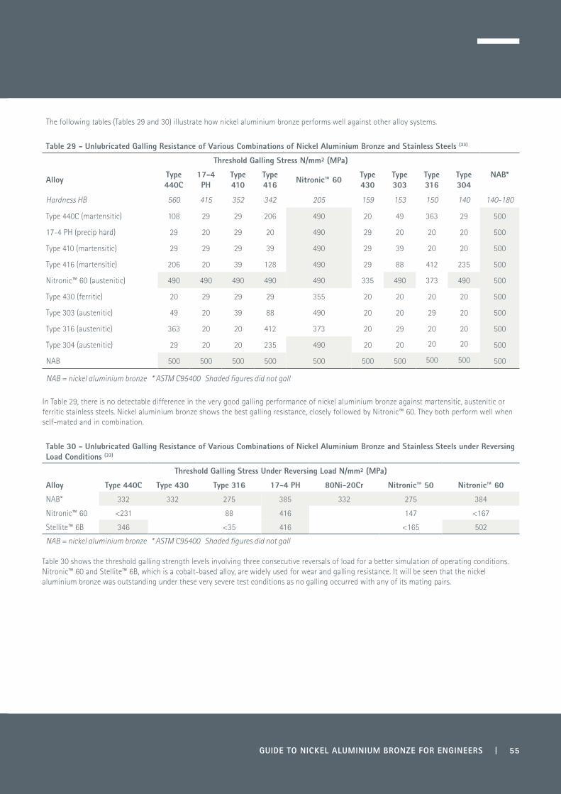
GUIDE TO NICKEL ALUMINIUM BRONZE FOR ENGINEERS | 55
The following tables (Tables 29 and 30) illustrate how nickel aluminium bronze performs well against other alloy systems.
Table 29 - Unlubricated Galling Resistance of Various Combinations of Nickel Aluminium Bronze and Stainless Steels (33)
Threshold Galling Stress N/mm² (MPa)
Alloy Type 440C
17-4PH
Type 410
Type 416 Nitronic™ 60 Type
430Type 303
Type 316
Type 304
NAB*
Hardness HB 560 415 352 342 205 159 153 150 140 140-180
Type 440C (martensitic) 108 29 29 206 490 20 49 363 29 500
17-4 PH (precip hard) 29 20 29 20 490 29 20 20 20 500
Type 410 (martensitic) 29 29 29 39 490 29 39 20 20 500
Type 416 (martensitic) 206 20 39 128 490 29 88 412 235 500
Nitronic™ 60 (austenitic) 490 490 490 490 490 335 490 373 490 500
Type 430 (ferritic) 20 29 29 29 355 20 20 20 20 500
Type 303 (austenitic) 49 20 39 88 490 20 20 29 20 500
Type 316 (austenitic) 363 20 20 412 373 20 29 20 20 500
Type 304 (austenitic) 29 20 20 235 490 20 20 20 20 500
NAB 500 500 500 500 500 500 500 500 500 500
NAB = nickel aluminium bronze * ASTM C95400 Shaded figures did not gall
In Table 29, there is no detectable difference in the very good galling performance of nickel aluminium bronze against martensitic, austenitic or ferritic stainless steels. Nickel aluminium bronze shows the best galling resistance, closely followed by Nitronic™ 60. They both perform well when self-mated and in combination.
Table 30 - Unlubricated Galling Resistance of Various Combinations of Nickel Aluminium Bronze and Stainless Steels under Reversing Load Conditions (33)
Threshold Galling Stress Under Reversing Load N/mm² (MPa)
Alloy Type 440C Type 430 Type 316 17-4 PH 80Ni-20Cr Nitronic™ 50 Nitronic™ 60
NAB* 332 332 275 385 332 275 384
Nitronic™ 60 <231 88 416 147 <167
Stellite™ 6B 346 <35 416 <165 502
NAB = nickel aluminium bronze * ASTM C95400 Shaded figures did not gall
Table 30 shows the threshold galling strength levels involving three consecutive reversals of load for a better simulation of operating conditions. Nitronic™ 60 and Stellite™ 6B, which is a cobalt-based alloy, are widely used for wear and galling resistance. It will be seen that the nickel aluminium bronze was outstanding under these very severe test conditions as no galling occurred with any of its mating pairs.
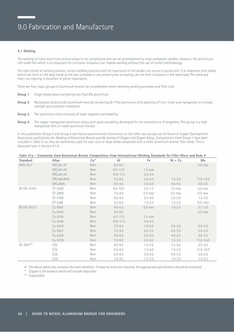
56 | GUIDE TO NICKEL ALUMINIUM BRONZE FOR ENGINEERS
9.0 Fabrication and Manufacture
9.1 Welding
The welding of nickel aluminium bronze alloys is not complicated and can be accomplished by most competent welders. However, the aluminium-rich oxide film which is so important for corrosion resistance can impede welding without the use of correct methodology.
The right choice of welding process, correct welding practices and the experience of the welder can ensure a sound joint. It is important that oxides, which can form on the base metal as the part is heated or are present prior to heating, do not form inclusions in the weld bead. Pre-weld and inter-run cleaning is therefore of prime importance.
There are four major groups of aluminium bronze for consideration when selecting welding processes and filler rods:
Group 1 Single phase alloys containing less than 8% aluminium.
Group 2 Multiphase alloys (nickel aluminium bronze) containing (8-11%) aluminium with additions of iron, nickel and manganese to increase strength and corrosion resistance.
Group 3 The aluminium silicon bronzes of lower magnetic permeability.
Group 4 The copper manganese aluminium alloys with good castability, developed for the manufacture of propellers. This group is a high manganese form of nickel aluminium bronze.
In this publication Group 2 and Group 4 are mainly examined and information on the other two groups can be found in Copper Development Association publications 85 Welding of Aluminium Bronze and 98 Joining of Copper and Copper Alloys. Compositions from Group 1 have been included in Table 31 as they are sometimes used for root runs on large welds completed with a nickel aluminium bronze filler metal. This is discussed later in Section 9.1.6.
Table 31a – Commonly Used Aluminium Bronze Compositions from International Welding Standards for Filler Wires and Rods #Standard Alloy Cu* Al Fe Ni + Co MnAWS A5.7 ERCuAl-A1 Rem 6.0-8.5 0.5 max
ERCuAl-A2 Rem 8.5-11.0 1.5 maxERCuAl-A3 Rem 10.0-11.5 2.0-4.5ERCuMnNiAl Rem 7.0-8.5 2.0-4.0 1.5-3.0 11.0-14.0ERCuNiAl Rem 8.5-9.5 3.0-5.0 4.0-5.5 0.6-3.5
BS EN 13347 CF 305G Rem 9.0-10.0 0.5-1.5 1.0 max 0.5 maxCF 309G Rem 7.0-9.0 0.5 max 0.5 max 0.5 maxCF 310G Rem 8.5-9.5 2.5-4.0 3.5-5.5 1.0-2.0CF 239E Rem 5.5-6.5 1.5-2.5 1.5-2.5 9.0-14.0
BS EN 24373 Cu 6061 Rem 4.5-5.5 0.5 max 1.0-2.5 0.1-1.0Cu 6100 Rem 6.0-8.5 0.5 maxCu 6180 Rem 8.5-11.0 1.5 maxCu 6240 Rem 10.0-11.5 2.0-4.5Cu 6325 Rem 7.0-9.0 1.8-5.0 0.5-3.0 0.5-3.0Cu 6327 Rem 7.0-9.5 0.5-2.5 0.5-3.0 0.5-2.5Cu 6328 Rem 8.5-9.5 3.0-5.0 4.0-5.5 0.6-3.5Cu 6338 Rem 7.0-8.5 2.0-4.0 1.5-3.0 11.0-14.0
BS 2901** C20 Rem 8.0-9.5 1.5-3.5 3.5-5.0 0.5-2.0C22 Rem 6.5-8.5 1.5-4.0 1.5-3.0 11.0-14.0C26 Rem 8.5-9.5 3.0-5.0 4.0-5.5 0.6-3.5C29 Rem 7.5-9.5 1.5-2.5 1.8-3.0 1.0-2.5
# The above table only contains the main elements. If impurity levels are required, the appropriate specification should be consulted. * Copper is the balance which will include impurities.** Superseded

GUIDE TO NICKEL ALUMINIUM BRONZE FOR ENGINEERS | 57
Table 31b – International Welding Standards from BS EN ISO 24373:2009
NumericalSymbol
Alloy Designation
USAAWS A5.7
USAUNS
JapanJIS Z3341JIS Z3202
EuropeEN 13347
EuropeEN14640
GermanyDIN 17331
Cu 6061 CuAl5Ni2Mn CuAl5Mn1Ni1
Cu 6100 CuAl7 ERCuAl-A1 C61000 CuAl8 CuAl8 2.0921
Cu 6180 CuAl10Fe1 ERCuAl-A2 C61800 YCuAl CuAl10Fe1 CuAl10 2.0937
Cu 6240 CuAl11Fe3 ERCuAl-A3 C62400 CuAl11Fe
Cu 6325 CuAl8Fe4Mn2Ni2 YCuAlNi B CuAl8Fe4Ni2
Cu 6327 CuAl8Ni2Fe2Mn2 YCuAlNi A CuAl8Ni2 2.0922
Cu 6328 CuAl9Ni5Fe3Mn2 ERCuAlNi C63280 YCuAlNi C CuAl9Ni4Fe3Mn2 CuAl9Ni5 2.0923
Cu 6338 CuMn13Al8Fe3Ni2 ERCuMnNiAl C63380 CuMn13Al6Fe2Ni2 CuMn13Al7 2.1367
9.1.1 Welding Processes
The ductility and weldability of aluminium bronzes allows the manufacture of preformed sections to produce items such as pressure vessels and pipes. One attractive feature of the aluminium bronzes is that it is possible to incorporate castings as well as forgings in a fabricated assembly. The single-phase aluminium bronze alloys are easier to cold work than the nickel aluminium bronze alloys and are therefore less expensive to roll into shape. However, the nickel aluminium bronze alloys are stronger and less sensitive to the stresses resulting from the heating and cooling cycles occurring during welding.
Welding is used on occasion to repair defects in castings but is sometimes prohibited for certain critical applications relating to Naval Standards. The process is also used for the repair of propellers that may become damaged in service or for reclamation of worn surfaces or areas that have been machined incorrectly in other types of fabrication.
9.1.2 Joining Processes
Soldering, brazing or oxy-acetylene welding processes are not recommended due to the nature of the protective aluminium-rich oxide film that forms on aluminium bronze.
9.1.3 Recommended Welding Processes
1) Tungsten inert gas (TIG) or gas tungsten arc (GTAW) welding 2) Metal inert gas welding (MIG) or gas metal arc welding (GMAW) 3) Manual metal arc (MMA) 4) Electron beam welding 5) Friction welding 6) Laser welding.
9.1.3.1 TIG/GTAW Process
The TIG/GTAW process is most suitable for the welding of thin material, for localised weld fabrication or for casting repairs. There are also two refinements of the basic process:
• Pulsed arc • Plasma and microplasma arc.
As the TIG process uses no flux, there is less risk of non-metallic inclusions. The process can also be used for initial root runs prior to MIG welding.In the TIG process the tungsten electrode is used to strike the arc which melts the substrate and the welding filler rod is fed manually into the molten pool. As the TIG process is localised and relatively slow, it is excellent for joining more delicate parts.

58 | GUIDE TO NICKEL ALUMINIUM BRONZE FOR ENGINEERS
To prevent oxidation of the weld pool, the arc is shielded with argon or helium gas.
The Pulsed Arc process has a more controlled heat input, which can be used for thin gauge material and for limiting the extent of the heat affected zone. In this process a lower current is used for striking the arc but is pulsed at regular intervals with a high current to increase the degree of fusion without overheating the weld pool.
The Plasma Arc process is used for much closer control of the penetration zone, where high quality welds are required for joining thin gauge tube and sheet. It is particularly suitable for mechanised operations rather than manual welding.
In the plasma process a constricted arc is generated between the nozzle and the tungsten electrode. A second laminar gas stream is also used which flows between the outer nozzle and the work piece for added protection.
The nozzle, which is water cooled, allows the arc to operate at a much higher temperature and enables a keyhole to be melted through the work piece into which the molten metal flows. The current is controlled to allow minimal penetration, and generally results in a smooth uniform run. Typical operating data is given in Table 32.
Argon is normally used to form the plasma, and also as the shielding gas, though it is also possible to add a proportion of hydrogen or helium to improve heat transfer efficiency of the arc.
Table 32 - Typical Operating Data for TIG Butt Welds in Aluminium Bronze and Nickel Aluminium Bronze (alternating current; argon shielded; pre-heat 150ºC maximum) (35)
Thickness mm
ElectrodeDiameter
mm
Filler RodDiameter
mm
Gas NozzleDiameter
mm
Gas Flow Ratel/min
WeldingCurrent
A
1.5 3.2 1.6 9.5-12 5-8 100-130
3 3.2 2.4 9.5-12 5-8 180-220
6 3.2 3.2 12-18 8-10 280-320
9 3.2 3.2-4.8 12-18 8-10 320-400
12 3.2 3.2-4.8 12-18 8-10 360-420
9.1.3.2 MIG/GMAW Process
The most efficient way of welding aluminium bronze and nickel aluminium bronze, particularly large fabrications, is by the MIG process. It allows the deposit of filler metal at a high rate.
In this process the filler wire is fed continuously through the gun rather than manually, as in the TIG method. This has two advantages: the wire is permanently shielded from oxidation by the gas stream and the process can be automated.
The filler wire becomes the electrode and the arc is struck between the work piece and the end of the filler wire. Argon is mainly used as the protective gas but, again, other mixes may be used such as argon/helium.
Due to the rate of metal deposition, this process is not recommended for thin gauge material or delicate welds.
As with TIG welding, this process can be modified using a pulsed current, which facilitates a much more controlled heat input and leads to a more uniform weld (Table 33 (35)).
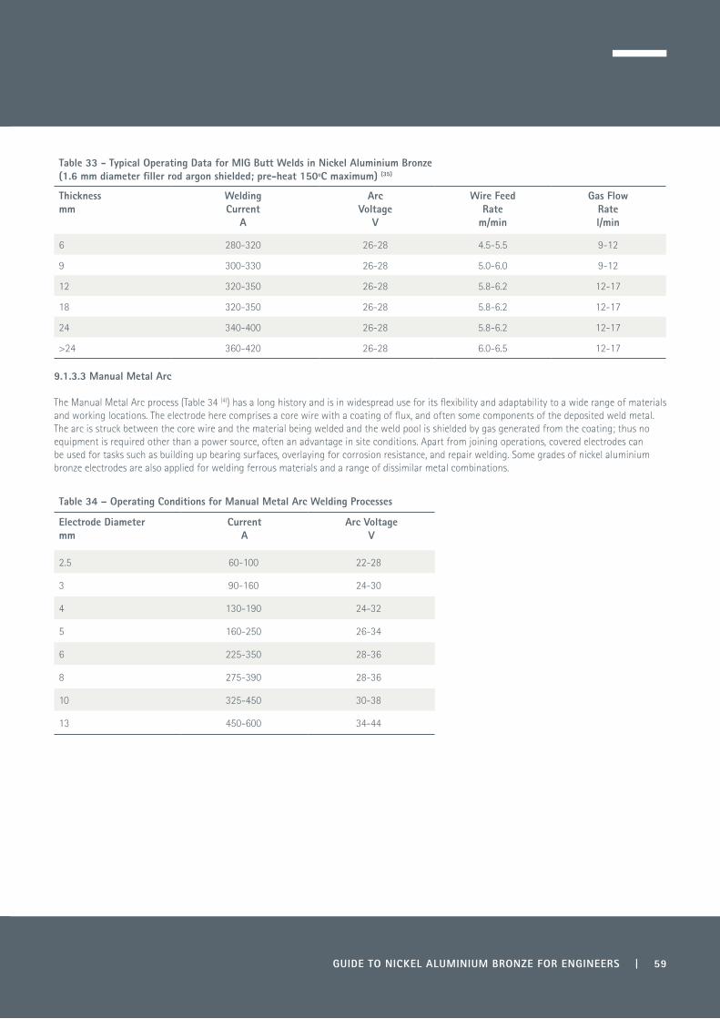
GUIDE TO NICKEL ALUMINIUM BRONZE FOR ENGINEERS | 59
Table 33 - Typical Operating Data for MIG Butt Welds in Nickel Aluminium Bronze (1.6 mm diameter filler rod argon shielded; pre-heat 150ºC maximum) (35)
Thicknessmm
WeldingCurrent
A
Arc Voltage
V
Wire FeedRate
m/min
Gas Flow Ratel/min
6 280-320 26-28 4.5-5.5 9-12
9 300-330 26-28 5.0-6.0 9-12
12 320-350 26-28 5.8-6.2 12-17
18 320-350 26-28 5.8-6.2 12-17
24 340-400 26-28 5.8-6.2 12-17
>24 360-420 26-28 6.0-6.5 12-17
9.1.3.3 Manual Metal Arc
The Manual Metal Arc process (Table 34 (4)) has a long history and is in widespread use for its flexibility and adaptability to a wide range of materials and working locations. The electrode here comprises a core wire with a coating of flux, and often some components of the deposited weld metal. The arc is struck between the core wire and the material being welded and the weld pool is shielded by gas generated from the coating; thus no equipment is required other than a power source, often an advantage in site conditions. Apart from joining operations, covered electrodes can be used for tasks such as building up bearing surfaces, overlaying for corrosion resistance, and repair welding. Some grades of nickel aluminium bronze electrodes are also applied for welding ferrous materials and a range of dissimilar metal combinations.
Table 34 – Operating Conditions for Manual Metal Arc Welding Processes
Electrode Diameter mm
Current A
Arc VoltageV
2.5 60-100 22-28
3 90-160 24-30
4 130-190 24-32
5 160-250 26-34
6 225-350 28-36
8 275-390 28-36
10 325-450 30-38
13 450-600 34-44
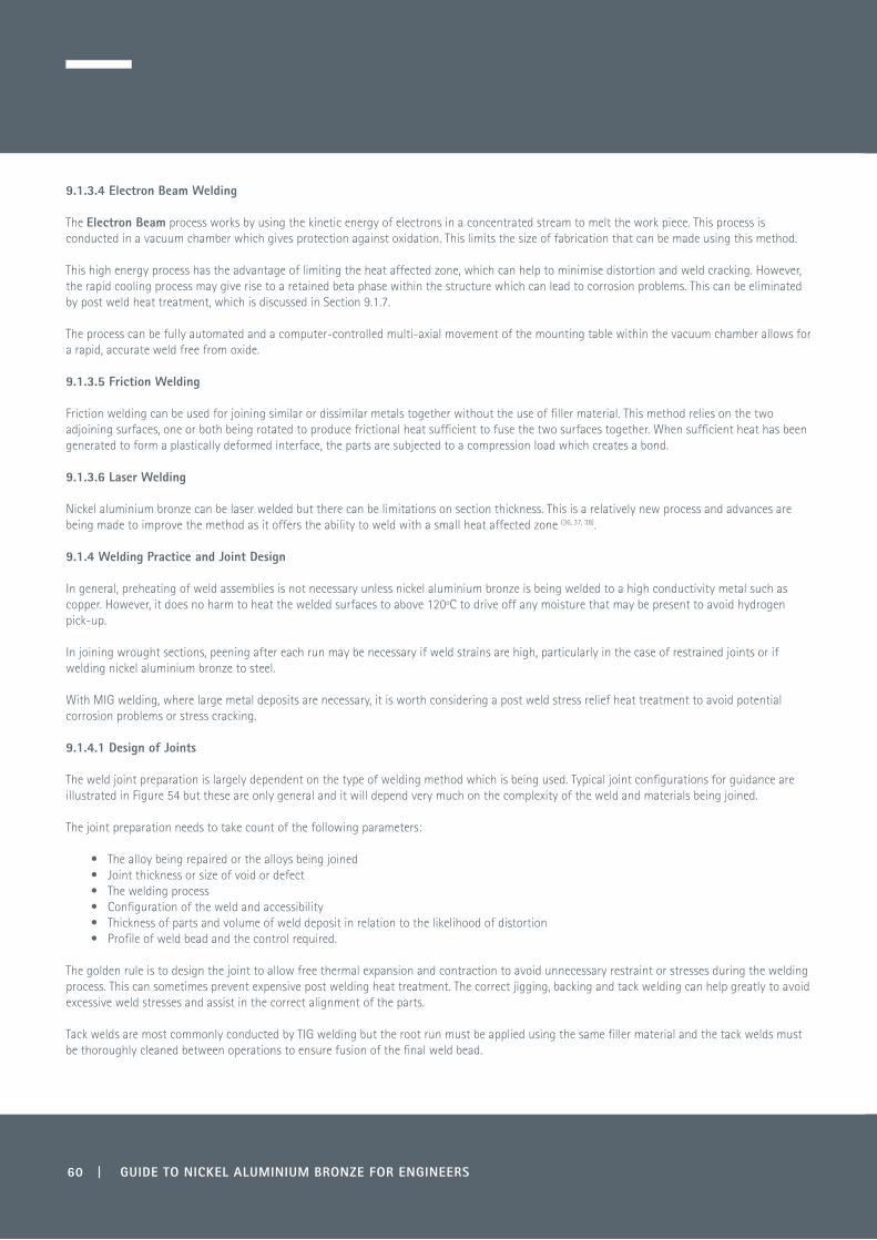
9.1.3.4 Electron Beam Welding
The Electron Beam process works by using the kinetic energy of electrons in a concentrated stream to melt the work piece. This process is conducted in a vacuum chamber which gives protection against oxidation. This limits the size of fabrication that can be made using this method.
This high energy process has the advantage of limiting the heat affected zone, which can help to minimise distortion and weld cracking. However, the rapid cooling process may give rise to a retained beta phase within the structure which can lead to corrosion problems. This can be eliminated by post weld heat treatment, which is discussed in Section 9.1.7.
The process can be fully automated and a computer-controlled multi-axial movement of the mounting table within the vacuum chamber allows for a rapid, accurate weld free from oxide.
9.1.3.5 Friction Welding
Friction welding can be used for joining similar or dissimilar metals together without the use of filler material. This method relies on the two adjoining surfaces, one or both being rotated to produce frictional heat sufficient to fuse the two surfaces together. When sufficient heat has been generated to form a plastically deformed interface, the parts are subjected to a compression load which creates a bond.
9.1.3.6 Laser Welding
Nickel aluminium bronze can be laser welded but there can be limitations on section thickness. This is a relatively new process and advances are being made to improve the method as it offers the ability to weld with a small heat affected zone (36, 37, 38).
9.1.4 Welding Practice and Joint Design
In general, preheating of weld assemblies is not necessary unless nickel aluminium bronze is being welded to a high conductivity metal such as copper. However, it does no harm to heat the welded surfaces to above 120ºC to drive off any moisture that may be present to avoid hydrogen pick-up.
In joining wrought sections, peening after each run may be necessary if weld strains are high, particularly in the case of restrained joints or if welding nickel aluminium bronze to steel.
With MIG welding, where large metal deposits are necessary, it is worth considering a post weld stress relief heat treatment to avoid potential corrosion problems or stress cracking.
9.1.4.1 Design of Joints
The weld joint preparation is largely dependent on the type of welding method which is being used. Typical joint configurations for guidance are illustrated in Figure 54 but these are only general and it will depend very much on the complexity of the weld and materials being joined.
The joint preparation needs to take count of the following parameters:
• The alloy being repaired or the alloys being joined• Joint thickness or size of void or defect• The welding process• Configuration of the weld and accessibility• Thickness of parts and volume of weld deposit in relation to the likelihood of distortion• Profile of weld bead and the control required.
The golden rule is to design the joint to allow free thermal expansion and contraction to avoid unnecessary restraint or stresses during the welding process. This can sometimes prevent expensive post welding heat treatment. The correct jigging, backing and tack welding can help greatly to avoid excessive weld stresses and assist in the correct alignment of the parts.
Tack welds are most commonly conducted by TIG welding but the root run must be applied using the same filler material and the tack welds must be thoroughly cleaned between operations to ensure fusion of the final weld bead.
60 | GUIDE TO NICKEL ALUMINIUM BRONZE FOR ENGINEERS

9.1.4.2 Weld Preparation
Weld preparation is the most important aspect of the process, as failure to adhere to the correct controls at this stage can lead to a failed weld, even though the subsequent welding procedure may be perfect.
If a defect is being repaired, then any trace of that defect must be removed by machining, grinding or pneumatic chipping, but still leaving as much of the parent metal as possible. It is essential the prepared area is left clean and smooth without excessive grooves or deep indents. Any such areas must have a minimum taper of 1 in 3 to allow correct filling of the defect. Once the defects have been removed and are not visible to the eye, it is always wise to check by non-destructive testing such as dye penetrant, ultrasonic inspection or radiography to make sure that all the defective area has been removed.
As a final precaution, final visual inspection should be carried out to ensure there is no trace of grindings, dirt, grease, moisture or remnants of non-destructive testing chemicals left in the repair area. The same requirement is necessary for butt joints to ensure perfect cleanliness.
Figure 54 – Butt welding profiles (35)
Rootgap: 0 - 1.5 mmRootface: 1.5 - 3 mm
60° - 90°
60° - 90°
60° - 90°
60° - 90° 60° - 90°
Rootgap: 0 - 1.5 mmRootface: 1.5 - 3 mm
Rootgap: 0 - 1.5 mmRootface: 1.5 - 3 mm
f) Single “V” butt
h) Single “V” butt
k) Double “V” butt l) Double “U” butt
j) Single “U” butt
g) Single “U” butt
e) Single “v” buttd) Single “V” Butt
Rootgap: 0 -1.5 mmRootface: 1.5 - 3 mm
c) Square butt
a) Close square butt b) Flange butt24 m
m
24 mm
18 mm
18 mm
12 mm
12 mm
6 mm
6 mm
3 mm
1.5 mm
1.5 mm
5° - 15°
5° - 15°
5° - 15°
Rootgap: 0 -1.5 mm
GUIDE TO NICKEL ALUMINIUM BRONZE FOR ENGINEERS | 61

9.1.5 Pre-heating and Weld Run Temperature Control
As mentioned earlier, pre-heating for joining nickel aluminium bronze to itself is not normally necessary. If pre-heating is necessary, then it is advisable to keep temperatures to 400ºC and below to avoid excursions into the ductility trough which exists at about 450-600ºC (Figure 55).
It is normally not necessary to pre-heat to more than 150-200ºC and it is wise to allow interpass temperatures to be in the region of 150ºC, and no more than 200ºC, which may mean allowing the weld heat affected zone to cool before restarting the next run. The temptation to ‘puddle’ large quantities of weld metal should be avoided.
Figure 55 - Variation of the maximum elongation with temperature of various aluminium bronze alloys in the as-cast condition showing the ductility drop by Weill-Couly (39)
Figure 56 shows low temperature pre-heating to approximately 150°C to drive off any moisture.
Figure 56 - Low temperature pre-heating of weld bead prior to second run (Courtesy Bailey Manufacturing, Stoke-on-Trent, UK)
900 800 700 600 500 400 300 200 100 0
90
80
70
60
50
40
30
20
10
0
Temperature, °C
Elon
gatio
n %
Alloy B
Alloy A
Alloy C
Weld “elongation”due to restrained
shrinkage
Alloy A - 9-10% Al, 5% Ni, 3.5-5% FeAlloy B - 9-10% Al, 2% Ni, 2% FeAlloy C - 7.6% Al, 0.7% Ni, 0.2% Fe
62 | GUIDE TO NICKEL ALUMINIUM BRONZE FOR ENGINEERS

9.1.6 Selection of Filler Materials for TIG/GTAW and MIG/GMAW Welding
Where possible, filler metals should match the composition of the parent metal as closely as possible.
Typical welding rod standards and compositions are listed in Tables 31a and 31b. The filler rods are commercially available in straight rods in various diameters for TIG welding and precision layer wound spools for the MIG process.
Filler rods and reels must always be kept under clean, dry conditions, avoiding oxidation where possible.
Nickel aluminium bronzes should be welded with the appropriate filler rod which conforms to Cu 6325/Cu 6327/Cu 6328 and can be cross-referenced to other International Standards (Table 31b).
The majority of aluminium bronze castings are made from alloys containing iron and nickel because of their higher strength, but this also limits their ductility and they can be more prone to cracking if restrained during the welding process.
Weill-Couly (39), an international authority on the welding of aluminium bronze castings, recommends using a filler rod containing aluminium 8.5-9.2%, nickel 2.7-3.0%, iron 1.0-2.0% and manganese 1% with the balance copper to provide a crack-free weld. This composition is used extensively by the French Navy for repair and for welded fabrications. There are also some further recommendations on composition to maximise corrosion resistance, optimising mechanical properties and maintaining a crack-free weld.
Although in general the specifications allow a higher aluminium content, it is advisable to stay within the range outlined by the following formula - Al ≤8.2 + Ni/2 - in order to prevent the formation of undesirable and embrittling metallurgical phases. Also, nickel content should be greater than iron, preferably by at least 0.5%. For optimum mechanical properties, the aluminium content needs to be in the range of 9.4-9.8%.
For larger welding runs it may be necessary to have an initial root run in a more ductile alloy such as Cu 6100, followed by a capping pass with Cu 6325, Cu 6327 or Cu 6328. The capping material should be of a composition to match the parent material as closely as possible to avoid any galvanic corrosion.
It is important to thoroughly clean the weld beads between runs and ensure the final topping run is sufficiently thick to prevent exposure of the underlying alloy when the final dressing or final machining takes place.
The manganese aluminium bronzes CuMn11Al8Fe3Ni3 are much easier to weld using Cu 3668 filler.
9.1.7 Post Weld Heat Treatment
9.1.7.1 Stress Relief
A simple stress relief anneal may be carried out at temperatures as low as 300-350ºC for a time dependent on section thickness for a minimum of one hour at temperature. This has no effect on mechanical properties.
9.1.7.2 Full Anneal
The full anneal consists of heating the metal above the re-crystallisation temperature of 650-750ºC at a rate of 100º per hour, holding at the set temperature for a minimum of six hours and allowing to air cool. This type of treatment can often be conducted after hot working to soften the alloy but is also conducted as a post weld anneal to equalise the weld structure to the parent metal (Figures 57 and 58).
The UK Navy developed a heat treatment to optimise corrosion resistance of 675ºC for six hours and cooling in still air for castings and this is now covered within their specifications for post weld heat treatment (Table 25).
The manganese aluminium bronze alloy CuMn11Al8Fe3Ni3 is more straightforward in welding behaviour but post weld heat treatment at 600-650ºC is still recommended, followed by air cooling to restore the corrosion resistance in the heat affected zone.
GUIDE TO NICKEL ALUMINIUM BRONZE FOR ENGINEERS | 63

Figures 57 and 58 - Selective annealing heat treatment of a welded flange on a desalination pump housing using resistance heating elements, 675ºC for six hours
(Courtesy Site Heat Treatment, Port Talbot, and Copper Alloys Ltd, Stoke-on-Trent, UK)
The graph below (Figure 59) gives an indication of the change in properties of nickel aluminium bronze with increasing annealing temperatures.
Figure 59 – Mechanical properties of nickel aluminium bronze CuAl9Fe5Ni5 with increasing annealing temperature (40)
600 650 700 750 800 850
750
700
650
600
550
500
450
400
350
300
20
15
10
5
0
Annealing temperature, °C
0.2% Proof strength
Elongation
Tensile strength
Percentage elongationTe
nsile
str
engt
h -
0.2%
pro
of s
tren
gth,
Nm
m-2
64 | GUIDE TO NICKEL ALUMINIUM BRONZE FOR ENGINEERS

9.2 Machining
Nickel aluminium bronze is relatively easy to machine on modern CNC equipment with the latest tooling technology. The machinability of this family of alloys ranges from 20-40% in a machinability index where free machining brasses are 100%.
The alloy can be machined with or without lubrication but it is recommended that lubrication is used on finishing operations, particularly where close tolerances are required. Being copper-based, heat generated can cause expansion of the product which, on finishing when cool, can result in contraction and take the product out of tolerance.
Heavy machining can also induce internal stress, which again can push the part being machined out of tolerance in the final operation.
Where heavy machining has taken place, it is advisable to conduct a low temperature stress relief at approximately 350°C for a minimum of one hour at temperature prior to final machining. Although nickel aluminium bronze does not normally suffer from stress corrosion cracking, this heat treatment helps as an added precaution.
As they are copper-based, the aluminium bronzes have a high recycling value and most manufacturing mills will offer buy-back deals on swarf. It is therefore important to keep the moisture content as low as possible by using dry cutting and ensure that the swarf remains free of other metals to prevent reducing the intrinsic value.
The nickel aluminium bronze alloys are not free machining and produce a curled swarf which can jam tooling and cause surface imperfections due to partial welding and tearing of the surface. This can occur particularly when machining bores and, under these circumstances, it is advisable to have a chip breaking profile on the tooling and have sufficient lubrication, sometimes under high pressure, so that swarf is removed from the cutting face. An alternative is to retract the tooling on a regular basis to prevent excessive metal build-up.
There has been a great advancement in tooling over the last decade with carbide indexing disposable tips, many with exotic coatings to enhance metal removal and produce better finishes. An international standard ISO 1832 has been devised which ensures a reproducible tip profile between suppliers - an example follows (Figure 60).
It is difficult to give exact machining guidelines, as feed and speed rates will depend on the size, age of lathes and CNC equipment and type of tips used. The following five pages also give some indication and guidance.
GUIDE TO NICKEL ALUMINIUM BRONZE FOR ENGINEERS | 65

BS ISO 1832:2004 Indexable Inserts for Cutting ToolsDesignation key for cutting tool materials made from carbide - Turning
Example
NF = non-ferrous and covers nickel aluminium bronze
Figure 60 – BS ISO 1832:2004 Designation key for cutting tool materials made from carbide - turning
The following illustrations are some typical CNC machining operations with tooling profiles with running speeds and feeds that would be used on nickel aluminium bronze.
The NMS grade of coated carbide indexable tip is recommended for roughing and removal of the bulk of the stock and, as an alternative, NM4 can be substituted which is also used for turning stainless steel. For heavy metal removal, then the size of the tip needs to increase.
For final machining and a fine finish, then the NF4 grade of tip is recommended.
66 | GUIDE TO NICKEL ALUMINIUM BRONZE FOR ENGINEERS

Insert Type Cutting Depth mm
Feed mm/rev
NF4 0.2-1.6 0.05-0.20
NMS 0.5-4.0 0.10-0.40
Machining Speeds/Type of Cut
NMS WSM20 Rough cut Cutting speed 130 m/min 0.28 mm/rev 3 mm depth of cut
NF4 WSM10 Fine finish Cutting speed 160 m/min 0.20 mm/rev
General Machine Parameters WSM10 WSM 20
Feed mm/rev 0.1 0.2 0.4 0.1 0.2 0.4
Cutting Speed 175 160 165 150 130
Figure 61- Negative profile turning inserts - coated carbide (Courtesy Walter Tooling)
Cut Main cutting edge
Cut Corner radius
9.2.1 Rough and Finishing Turning
NF4
- Finishing stainless materials- Finishing alloys with difficult cutting properties- Finishing long-chipping steel materials- Curved cutting edge for cutting pressure
reduction.
NMS
- Medium machining, especially for high- temperature alloys (Ni, Co, Fe-based alloys)
- Precise cutting edge design- Alternative to NM4 stainless geometry.
GUIDE TO NICKEL ALUMINIUM BRONZE FOR ENGINEERS | 67

9.2.2 Milling
Tool Holder Cutting Insert
Cutting edge diameter Dc 50 mm Cutting edge length I 12.7 mmMaximum cutting edge diameter Da 63 mm Insert thickness S 6.4 mmAdapter diameter, workpiece-side d1 22 mm Wiper edge length b 1.5 mmMaximum overhang I4 40 mm Maximum depth of cut Lc 6.5 mmPeripheral effective cutting edge count z 6 mm
Bottom pre-machiningWorking engagement ae 25 mmDepth of cut ap 5 mmNumber of passes in AE direction NOPae 4Number of passes in AP direction NOPap 1Cutting speed 285 m/minSpindle speed 1690 rpmFeed per tooth 0.17 mmFeed speed 1720 mm/min
Figure 62 - Milling of plain surface(Courtesy Walter Tooling)
Tool Holder Cutting Insert
Operation type Pre-machiningDepth 5 mmWidth 100 mmLength 100 mmCutting edge diameter 50 mm
68 | GUIDE TO NICKEL ALUMINIUM BRONZE FOR ENGINEERS

9.2.3 Slot Milling
Figure 63 – Slot milling (Courtesy Walter Tooling)
Type carbideHelix angle 30°Cutting edge diameter Dc 10 mmCutting edge tolerance class e8Adapter diameter d1 10 mmUsable length L3 11 mmMaximum depth of cut Lc 11 mmOverall length I1 66 mmMaximum overhang I4 26 mm
Slot DescriptionOperation Pre-machiningDepth 10 mmWidth 10 mmLength 50 mmCorner radius at the side 5 mmCutting edge diameter 10 mm
Working engagement 10 mm 10 mmDepth of cut 2.5 mm 2.5 mmNo of passes NOPap 4Cutting speed 36.4 mm/min 36.4 mm/minSpindle speed 1160 rpm 1160 rpmFeed per tooth 0.0684 mm 0.137 mmFeed speed 238 mm/min 476 mm/min
Drilling for pre-machining Bottom pre-machining
GUIDE TO NICKEL ALUMINIUM BRONZE FOR ENGINEERS | 69

9.2.4 Threading
Figure 64 – Threading(Courtesy Walter Tooling)
Thread DescriptionType MDiameter 10 mmPitch 1.5 mmClass tolerance 6HLength 20 mmDiameter size M10Hand RightClearance distance 3 mm
Material type carbide Helix angle 20°Thread pitch P 1.5 mmMaximum length of cut Lc 21 mmCutting edge diameter Dc 7.5 mmUsable length I1 63 mmMaximum overhang I4 27 mmAdapter diameter d1 8 mm
Cutting speed 69.3 m/minSpindle speed 2940 rpmFeed per tooth 0.0968Feed speed 1140 mm/min
70 | GUIDE TO NICKEL ALUMINIUM BRONZE FOR ENGINEERS

9.3 Mechanical and Non-destructive Testing
9.3.1 Mechanical Testing
The degree of mechanical testing in wrought and cast products depends very much on the function of the component. In military and defence applications, the number of test pieces and their selection in terms of directionality and location is directly linked to the final application and can be complex with regard to how critical this is to safety and successful operation.
It is possible for test pieces for castings to be designed into the casting itself or poured from the same melt into dedicated test piece moulds.
With wrought products it is normal practice to select the test pieces by cutting a section out of the product. On occasion where the section is of a size such as a thin-walled ring that makes it difficult to cut a standard-size test bar, then a test piece can be manufactured at the same time at the same temperature with a reduction that matches the product.
In ASTM E 8 Paragraph 6.16.1 (Location of Test Specimens), wrought products 40 mm in diameter or thickness are normally taken mid-radius or thickness, whereas products 40 mm or less are taken from the centre of the section.
9.3.2 Non-destructive Testing
Table 35 provides a selection of international non-destructive testing standards for nickel aluminium bronze for both casting and wrought products. The majority of world specifications for copper-based alloys make use of those relating to steels for the methodology.
Radiographic examination is normally only applied to castings but can be used in wrought products where ultrasonic penetration is difficult due to grain size.
Liquid Penetrant examination is applied to both castings, welds and wrought products and is most effective on finished products where surface defects are more easily classified. It can also be used prior to expensive machining or welding operations to determine the level of defects.
Ultrasonic examination is used mainly on wrought products as it relies on a fine grain size for accurate defect determination. It may be used on castings where the profile is a regular shape and the grain size permits penetration of the sound wave.
This method of examination can cover a wide range of products and techniques for the detection of defects in welds, pipe, tubes, plates, wrought forgings and bars, as well as thickness determination in plates and tubing. The method often relies on the use of calibration blocks manufactured by the same process route and the same material into which flat bottom holes are drilled, normally from 1.5 mm diameter and upwards. The flat bottomed holes are used to set the calibration standard to identify the size and location of defects.
Table 35 - International Non-destructive Testing StandardsCountry Standard DescriptionUK Def Stan 02-729 Part 1 Radiography
Part 2 Liquid penetrantPart 3 Ultrasonics
Europe EN 10228 Part 2 Liquid penetrant
Part 3 Ultrasonics
EN 12517-1 Non-destructive testing of welds
EN ISO 5579:2013 Radiography
USA MIL STD 271F Non-destructive testing
NAVSEA T9074-AS-GIB-010/271 1997 Non-destructive testing
ASTM E 2375 Ultrasonics
ASTM E 1417 Liquid penetrant
ASTM E 1032 Radiography weldmentsASTM E 1742 Radiography
GUIDE TO NICKEL ALUMINIUM BRONZE FOR ENGINEERS | 71

9.4 Manufacture - Casting Processes
Nickel aluminium bronze can be cast by a range of different methods:
• Sand casting• Shell mould• Ceramic mould casting• Investment casting• Die or permanent mould casting• Static billet casting.
Details of the above processes can be found in Cast and Wrought Aluminium Bronzes, Properties, Processes and Structure by Harry Meigh, commissioned by Copper Development Association in 2000 and available from Maney Publishing.
• Continuous casting• Centrifugal casting.
The nickel aluminium bronzes are normally cast within the temperature range of 1150-1200ºC and the CuMn13Al8Fe3Ni3, 1030-1150ºC.
9.4.1 Modern Casting Techniques
In the past ten years computer technology has advanced enormously in 3D simulation software in the fields of sand casting and continuous casting (Figures 65 and 66).
Flow modelling allows the foundryman to see how molten metal will flow through gating systems or continuous casting moulds. The programs can predict convection, conduction and radiation in the mould cavity, allowing the foundry technician to analyse the casting, gating and mould design. By this method it is possible to predict and minimise flow-related defects such as misruns due to premature solidification, oxide formation or mould erosion due to excessive velocities during filling.
Figure 65 - Casting simulation showing a prediction for soundness(Courtesy Inoxyda SA, France)
Most programs also allow the foundryman to assess and modify how the casting will solidify before making patterns, dies, gating systems and costly mistakes. This is particularly important when casting complex castings such as propellers. Casting simulation helps to shorten lead times, produce higher quality and improve yield. All of this means lower costs, higher profits and improved marketability for the foundry.
72 | GUIDE TO NICKEL ALUMINIUM BRONZE FOR ENGINEERS
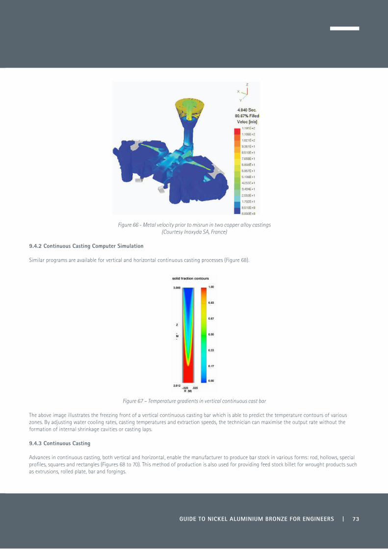
Figure 66 - Metal velocity prior to misrun in two copper alloy castings(Courtesy Inoxyda SA, France)
9.4.2 Continuous Casting Computer Simulation
Similar programs are available for vertical and horizontal continuous casting processes (Figure 68).
Figure 67 – Temperature gradients in vertical continuous cast bar
The above image illustrates the freezing front of a vertical continuous casting bar which is able to predict the temperature contours of various zones. By adjusting water cooling rates, casting temperatures and extraction speeds, the technician can maximise the output rate without the formation of internal shrinkage cavities or casting laps.
9.4.3 Continuous Casting
Advances in continuous casting, both vertical and horizontal, enable the manufacturer to produce bar stock in various forms: rod, hollows, special profiles, squares and rectangles (Figures 68 to 70). This method of production is also used for providing feed stock billet for wrought products such as extrusions, rolled plate, bar and forgings.
GUIDE TO NICKEL ALUMINIUM BRONZE FOR ENGINEERS | 73

74 | GUIDE TO NICKEL ALUMINIUM BRONZE FOR ENGINEERS
Modern grain refining techniques (Figure 71), utilising vibrating or specialised die design, have enabled the production of fine grained bar stock which is very close in properties to its wrought counterparts.
Figure 68 - Vertical and horizontal continuous casting (Courtesy Finkelstein Metals Ltd, Israel)
Figure 69 – Horizontal slab casting (Courtesy Alfred Wertli, Switzerland)
Figure 70 – Horizontal 7 strand bar casting (Courtesy Alfred Wertli, Switzerland)

GUIDE TO NICKEL ALUMINIUM BRONZE FOR ENGINEERS | 75
Figure 71 – Grain refining in continuous casting (Courtesy Copper Alloys Ltd, Stoke on Trent, UK)
Figure 71 shows the macrostructures of vertically cast bar, with and without grain refining. The refined structure on the left has equiaxed and finer grains than the equivalent non-refined bar on the right, which shows a coarser columnar structure with dendrites angled in the direction of casting and heat extraction. Continuous casting techniques also eliminate the turbulence and chance of oxide inclusions—which historically has been a major problem in production of aluminium bronze—by casting from the base of the holding furnace.
9.4.4 Centrifugal Casting
This method of casting allows large diameter tubes and rings to be cast with flanges and recesses which are not possible by continuous casting. The centrifugal process is used both in the vertical and horizontal plane (Figures 72 and 73) and metal is spun onto an outer cast iron mould which can be water cooled. The process allows the oxides present, as they are less dense, to remain at the inner diameter which is later removed by machining. The input metal is carefully weighed before pouring so that the correct inside diameter is created, taking into account machining allowance for the inner and outer diameter.
Figure 72 – Horizontal centrifugal casting of flanged tube(Courtesy custompart.net, USA)
Figure 73 – Casting a tube

9.5 Wrought Hot Working Processes
Following casting by static or continuous cast process, there are a number of options for further processing:
• Extrusion• Rolling• Forging.
9.5.1 Hot Working Ranges
The nickel aluminium bronzes within the mid-range of aluminium content 8.5-10% are normally hot worked within the temperature range 900-950ºC and down to 700-750ºC in the final stages. As the aluminium content increases, then the hot working temperature can be reduced, forexample CuAl11Fe6Ni2 can be processed at 880-920ºC, but needs to be finished at at least 750ºC to avoid low ductility at room temperature.
The manganese aluminium bronzes CuMn13Al8Fe3Ni3 can be hot worked at 800-850ºC and are still reasonably malleable at 650ºC.
9.5.2 Cold Working
Nickel aluminium bronze alloys have limited ability to be cold worked due to lower ductility compared with duplex and single phase alloys. Cold work is normally only used as a sizing operation for extruded products and is limited as the alloy rapidly work hardens.
9.5.3 Extrusion
Nickel aluminium bronze is normally extruded using the direct extrusion method (Figure 74). Extrusion is a low yield process with up to 30% loss due to ‘back end defect’, which is a result of oxides flowing into the centre of the bar towards the end of the extrusion operation.
Figure 74 – Direct horizontal extrusion
However, extrusion remains an important way for producing small diameter bars in the range of 3-75 mm diameter. The process imparts longitudinal properties and bars can be produced close to the finished size with minimal machining allowance.
9.5.4 Rolling
In terms of cost, rolling produces a much better yield than extrusion (in the region of 80%) but it tends to be more labour intensive as, due to relatively low volumes compared with steel rolling, the aluminium bronzes are normally produced on manual mills (Figure 75).
The process also imparts longitudinal properties but, due to the inability of the rolling operation to maintain close tolerance, the product requires a much larger machining allowance than extruded products.
76 | GUIDE TO NICKEL ALUMINIUM BRONZE FOR ENGINEERS
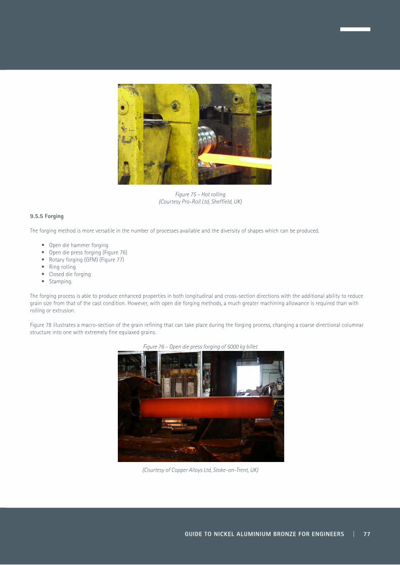
Figure 75 – Hot rolling(Courtesy Pro-Roll Ltd, Sheffield, UK)
9.5.5 Forging
The forging method is more versatile in the number of processes available and the diversity of shapes which can be produced.
• Open die hammer forging • Open die press forging (Figure 76)• Rotary forging (GFM) (Figure 77)• Ring rolling• Closed die forging• Stamping.
The forging process is able to produce enhanced properties in both longitudinal and cross-section directions with the additional ability to reduce grain size from that of the cast condition. However, with open die forging methods, a much greater machining allowance is required than with rolling or extrusion.
Figure 78 illustrates a macro-section of the grain refining that can take place during the forging process, changing a coarse directional columnar structure into one with extremely fine equiaxed grains.
Figure 76 – Open die press forging of 5000 kg billet
(Courtesy of Copper Alloys Ltd, Stoke-on-Trent, UK)
GUIDE TO NICKEL ALUMINIUM BRONZE FOR ENGINEERS | 77
GUIDE TO NICKEL ALUMINIUM BRONZE FOR ENGINEERS | 79
10.0 Summary Guidelines for Engineers
In order to assist design engineers in understanding the complexities involved in maximising the unique properties of nickel aluminium bronze, some of the main points from the earlier sections are listed below:
• For maximum corrosion resistance in seawater and other corrosive environments ensure the nickel content exceeds the iron content, preferably by 0.5% or more.
• Castings and welded structures should be annealed between 675 and 725ºC for a minimum of six hours, depending on section, to maximise the corrosion resistance.
• Avoid the creation of crevices in engineering designs, particularly in areas where there is likely to be stagnant seawater.
• It is vitally important in the commissioning of equipment, particularly in seawater applications, that the system is flushed through with clean aerated seawater for extended periods if possible. This helps build up the protective layer and is important for long-term corrosion resistance.
• Avoid designs or media which may become polluted or contaminated with sulphide-generating bacteria.
• Investigate galvanic interaction as regards relative position of the metals coupled together in the galvanic table and their relative surface area ratios. If a small area of nickel aluminium bronze is coupled to a relatively large area of a more noble alloy, as might be the case with fasteners, then consideration should be given to electrical isolation.
• If using washers or seals, avoid products which may contain graphite as this can create galvanic/crevice corrosion problems due to its high nobility in the galvanic table.
• If flowing seawater contains a high level of contaminants as sand, give consideration to filter systems to avoid erosion/corrosion and limit flow rates to less than 4.3 m/sec.
• Cathodic protection can change the electrochemical potential of metals and may also reduce the natural high biofouling resistance of aluminium bronzes.
• In seawater flow systems, avoid rapid changes in section, protrusions or cavities where erosion corrosion can occur through turbulent flow. Erosion corrosion does not always occur at the change of section but can be generated some distance downstream from the creation point.
• Avoid contact with mercury, or mercury salts, moist ammonia compounds, nitrates and moist sulphur dioxide as these can lead to stress corrosion cracking.
• When welding, use matching filler rods, particularly for the capping pass.
• If heavy machining has taken place and there is difficulty in holding final machining tolerances, give consideration to a low temperature stress relief. For removing machining stress, heat treatments can be conducted at temperatures between 300-450ºC for various times depending on cross-section and these have little impact on mechanical properties or microstructures.
• Give consideration to recycling used components and turnings that are generated and keep them free from other contaminants.

80 | GUIDE TO NICKEL ALUMINIUM BRONZE FOR ENGINEERS
11.1 General References
1) A A Read and R H Greaves. The Influence of Added Metal on Some Copper Aluminium Alloys. The Engineer. March 1914. Institute of Metals No11 page 342.
2) R Genders, R C Reader and V T S Foster. Die Casting of Copper-Rich Alloys. J Inst Met 1928, 40, 187.3) UK Defence Standardisation website www.dstan.mod.uk via Defence Gateway - Civilian access to Dstan.4) P J Macken and A A Smith. The Aluminium Bronzes. Copper Development Association Publication 31. 1966.5) A Dick. Deutsches Patent No 83388. 1984.6) A A Read and R H Greaves. The Influence of Nickel on some Copper-Aluminium alloys. J Inst of Metals, 1914, XI, 169.7) H T Gough and D G Sopwith The Resistance of Some Special Bronzes to Fatigue and Corrosion Fatigue. J Inst. Metals, 1937, 69, 143.8) M Sadayappan, F A Fasoyinu, R Orr, R Zevadil and M Sahoo. Impurity Limits in Aluminium Bronzes. Progress report, Year 1, Materials Techology
Laboratory, CAN-MET. March 1998.9) M Kanamori, S Ueda and S Matsuo. On the Corrosion Behaviour of Copper Aluminium-Nickel-Iron Cast Alloys in Sea Water’, Nippon Kinzoku
Gakkai, 1960, 24, (5), 268-71.10) H Meigh. Cast and Wrought Aluminium Bronzes, Properties, Processes and Structures. Commissioned by Copper Development Association. 2000. Published by Maney Publishing.11) R I Jaffee and R H Ramsey. Metal Progress, 1948, 54, 57-83.12) C H Thornton. Aluminium Bronze Alloys Technical Data. Copper Development Association Publication 82. January 1986.13) A Butts and P L Reiber. Magnetism in Copper Alloys: The Effect of Iron as an Impurity. Proc ASTM 1949, 49, 857-86.14) J C Rowlands. Studies of the Preferential Phase Corrosion of Cast Nickel Aluminium in Sea Water. Metal Corr. 1981, 2, 1346-1351.15) G W Lorimer, F Hasan, J Iqbal, N Ridley. Br Corros J 21 (1986) 244-248.16) J A Wharton, R C Barik, G Kear, R J K Wood, K R Stokes and F C Walsh. The Corrosion of Nickel Aluminium Bronze in Sea Water. Corrosion
Science 47, 2005 3336-3367.17) R C Barik, J A Wharton, R J K Wood, K R Stokes. Environment and Mitigation - Nickel Aluminium Bronze Pitting Corrosion in Seawater.
University of Southampton School of Eng. Science.18) R Francis. Galvanic Corrosion - A Practical Guide. NACE International Press 2001.19) 1997. Chain for Nation’s Largest Roller Gate Dam Meets Materials’ Requirements. Mater Performance, Vol 36, No 3; pp 57-58.20) A Schüssler and H E Exner. The Corrosion of Nickel-Aluminium Bronzes in Seawater-1. Protective Layer Formation and the Passivation
Mechanism. Institute of Materials Science, Karlsruhe Germany.21) J P Ault. Erosion Corrosion of Nickel Aluminium Bronze in Flowing Sea Water. Nat Ass of Corr Eng Report No 281. March 1995.22) RF Materials Ltd. Private Communication. 2015.23) J L Heuze, B Masson, A Karimi. Comportement à l’Erosion de Cupro-aluminium Complex. Association Technique Martime et Aeronautique,
session 1991.24) I S Pearshall, Chartered Mechanical Engineer, Oct 1987, 31.25) I S Pearshall, Chartered Mechanical Engineer, July 1974.26) R Francis. The Corrosion of Copper and its Alloys: A Practical Guide for Engineers. NACE International. 2010.27) P Collins and D J Duquette. Corrosion Fatigue Behaviour of a Duplex Aluminium Bronze Alloy. Corrosion (USA) April 1978, 34 (4) 119-124.28) Ship Department 18, Design and Manufacture of Nickel Aluminium Bronze Sand Castings. UK Ministry of Defence (PE) 1979. NB SPD 18
later became NES 747 Part 5, then Def Stan 02-747 Part 5. Currently it is Maritime Acquisition Publication (MAP) No. 01-102. Design and Manufacture of Nickel Aluminium Bronze Sand Castings. Issue 1 December 2006.
29) Aluminium Bronze Alloy Corrosion Resistance Guide. Copper Development Association Publication 80, 1990.30) J W Oldfield and G L Masters, Collation of Data Comparing Properties of Aluminium Bronze with Cast Stainless Steels and Ni-Resist in Offshore
Seawater Environments. Copper Development Association Publication 115, 1996.31) E Rabald. Corrosion Guide. Second Edition. Elsevier 1965.32 M Cook, W P Fentiman and E Davis. Observations on the Structure and Properties of Wrought Copper-Aluminium-Nickel-Iron Alloys. J Inst Met
1951-1952, 80, 419-429.33) W J Schumacker. Wear and Galling can Knock out Equipment. Chemical Eng. New York. May 1977.34) J Cronin and J Warburton Transitions in Fretting. The Comparative Behaviour of Six Materials. Tribol Inst 21, 309-315. Dec 1988.35) L Brown. Joining of Copper and Copper Alloys. Copper Development Association Publication 98, 1994.36) K Petrolonis, 1993 07 5301 Laser Beam Welding Nickel Aluminium Bronze Cu-9Al-4Fe-4Ni.37) Kenny H Leong, Peter A Kirkham and Kenneth C Meinet Jr. Journal of Laser Applications, 12, 181, 2000.38) Calvin V Hyatt, National Defence Research and Development Branch, Technical Memorandum 96/227. March 1997, Review of Literature related
to Microstructure Development during Laser Surface Engineering of Nickel Aluminium Bronze.39) P Weill–Couly. Welding Aluminium Bronze Castings. Proc Int Conf on Welding of Castings. Welding Institute Cambridge 1977. Vol 1 253-266.40) C Soubrier and M Richard. Soudures de pièces en cupro-aluminium: étude electro-chemique du choix du recuit. Founderie, Fondeur
d’aujourd’hui. January 1991. 101.
11.0 References and Further Information

GUIDE TO NICKEL ALUMINIUM BRONZE FOR ENGINEERS | 81
11.2 Publications from Copper Development Association (CDA)
The following publications, giving reference to aluminium bronzes, can be downloaded from the Resource Library on Copper Development Association’s website - www.copperalliance.org.uk:
No 80 Aluminium Bronze Alloys Corrosion Resistance GuideNo 81 Designing Aluminium Bronze CastingsNo 82 Aluminium Bronze Alloys Technical DataNo 83 Aluminium Bronze for IndustryNo 85 Welding Aluminium BronzeNo 86 Aluminium Bronze Essential for IndustryNo 98 Joining of Copper and Copper Alloys: Cost-Effective ManufacturingNo 106 Corrosion Resistance of Copper and Copper AlloysNo 115 Collation of Data Comparing Properties of Aluminium Bronze with Cast Stainless and Ni-Resist in Offshore Seawater EnvironmentsNo 126 Resistance to Wear of Aluminium BronzeNo 206 Copper Alloys for Marine Environments
11.3 Other Publications
Cast and Wrought Aluminium Bronzes - Properties, Processes and Structure by Harry Meigh, commissioned by Copper Development Association, 2000, published by Maney Publishing.
The Corrosion Performance of Metals for the Marine Environment, European Federation of Corrosion No 63. Joint Publication with NACE. Maney Publishing. 2012.
The Corrosion of Copper and its Alloys: A Practical Guide for Engineers. R Francis, NACE International, 2010.
Kupfer Aluminium Legierungen (Copper Aluminium Alloys). Deutsches Kupferinstitut, Copper Alliance. www.kupferinstitut.de

82 | GUIDE TO NICKEL ALUMINIUM BRONZE FOR ENGINEERS
Appendix
Standards and Designations
The tables in this Appendix illustrate the major world specifications covering chemical and mechanical properties of cast and wrought nickel aluminium bronzes.
International StandardsTable App1 Nickel Aluminium Bronze - Wrought .............83Table App2 Nickel Aluminium Bronze – Cast ......................85
UK: Nickel Aluminium Bronze - WroughtTable App3 Chemical Compositions ........................................86Table App4 Mechanical Properties ..........................................86
UK: Nickel Aluminium Bronze – CastTable App5 Chemical Compositions ........................................87Table App6 Mechanical Properties ..........................................87
UK/European: Nickel Aluminium Bronze – Wrought Table App7 Chemical Compositions ........................................88Table App8 Mechanical Properties ..........................................89
UK/European: Nickel Aluminium Bronze – CastTable App9 Chemical Compositions ........................................90Table App10 Mechanical Properties ..........................................90
France: Nickel Aluminium Bronze – Wrought Table App11 Chemical Compositions ........................................91Table App12 Mechanical Properties ..........................................91
France: Nickel Aluminium Bronze – CastTable App13 Chemical Compositions ........................................92Table App14 Mechanical Properties ..........................................92
Germany: Nickel Aluminium Bronze – WroughtTable App15 Chemical Compositions ........................................93Table App16 Mechanical Properties ..........................................94
Germany: Nickel Aluminium Bronze – CastTable App17 Chemical Compositions ........................................95Table App18 Mechanical Properties ..........................................95
USA: Nickel Aluminium Bronze – WroughtTable App19 Chemical Compositions ........................................96Table App20 Mechanical Properties ..........................................96
USA: Nickel Aluminium Bronze – CastTable App21 Chemical Compositions ........................................97Table App22 Mechanical Properties ..........................................98

GUIDE TO NICKEL ALUMINIUM BRONZE FOR ENGINEERS | 83
International Standards
Table App1 – Nickel Aluminium Bronze - Wrought
International Standards
MaterialDesignation Sheet and Plate Rod and
Bar ProfileForgings andStampings Tube
UK Def Stan Nickel Aluminium Bronze 02-833 Part 1* 02-833 Part 2
Issue 3 Amd 3 (2013)02-833 Part 2 Issue 3 Amd 3 (2013)
Def Stan Nickel Aluminium Bronze 02-879 Part 1 Issue 1 (2011) Annex F
BS EN CW304GCW306GCW307GCW308G
1653 (1998)
1653 (1998) 12163 (2011), 12167 (2011)12163 (2011), 12167 (2011)
14420 (2011)12165 (2011), 12420 (2011)12165 (2011), 12420 (2011)12165 (2011), 12420 (2011)
BS Cu-Al-Ni-FeCA104CA104 CA104
2870 : (1980) 2B 23 : (2009) 2874 : (1986) 2872 : (1989)
2B 23 : (2009) 2874 : (1986)
DTD 197A
US ASTM UNS C63000
UNS C63020UNS C63200
B171B150 TQ50
B150, B124
B150, B124
B124, B283
B124, B283
ASME UNS C63000 SB171 SB150 SB283
Federal UNS C63000 UNS C63200
QQ-C-00465B (1)QQ-C-00465B (1)
MIL-B-161666 MIL-B-24059 (3)
SAE UNS C63000UNS C63000
J461 J463
J461 J463
AMS UNS C63000UNS C63020
46404590
46404590
46404590
Australia AS 2738-2 632
Austria ONORM M 3409 (1985) M 3412-1 M 3413-1 M 3412-1
China GB 5233 (1985) QAl10-4-4 GB4429
Czech Republic CSN 42 3096-3
CuAl10Fe4Ni442-131942-3081-2
42-144042-1540
42-1320
European EN
CW304GCW306GCW307GCW308G
1653 (1998)
1653 (1998) 12163 (2011), 12167 (2011)12163 (2011), 12167 (2011)
14420 (2011)12165 (2011), 12420 (2011)12165 (2011), 12420 (2011)12165 (2011), 12420 (2011)
Continued on page 84

International Standards Continued from page 83
International Standards
MaterialDesignation Sheet and Plate Rod and
Bar ProfileForgings andStampings Tube
France NF A CuAl9Ni5Fe4
CuAl9Ni5Fe351-113 (1983)51-115 (1983)
51-116 (1989) 51-116 (I989)
NFL UA 10NUA 11N
14-70514-706
14-70514-706
NCT 15-641-12 15-641-12
GAM MM11 MM11
Germany DIN CuAl8Mn
CuAl9Ni7WL 2.0958WL 2.0967 WL 2.0967
DIN WN 2.0971, 2.0966WN 2.0936, 2.0966, 2.0978WN 2.0936, 2.0966, 2.0978WN 2.0936, 2.0966, 2.0978
17670-Parts 1, 217672-Parts 1, 2
17678-Parts 1, 217671-Parts 1, 2
Hungary MSZ 711-1:1977 711-3 711-6
Italy 7989-1-(1974) √ √ √ √
Japan JIS C6301 H3100
Netherlands ISO 428 ISO 1634-2 ISO 1638 ISO 1640
Poland PN /H-87051 (1992) /H-93620 (1982) /H-74586 (1997)
Portugal NP 3638 3674 3636
37443745
Russia GOST 18175 BrAZN10-4-4 GOST 1628
GOST 1206GOST 1206
Spain UNE 37-103-1
Switzerland SN 211 605 (1986)
ISOISO 428:1983 CuAl10Fe5Ni5 1634-2 1637
16391640
* Def Stan 02-833 Part 1 has been superseded by Def Stan 02-879 Part 1
84 | GUIDE TO NICKEL ALUMINIUM BRONZE FOR ENGINEERS

International Standards
Table App2 – Nickel Aluminium Bronze - Cast
InternationalStandards
MaterialDesignation Ingot Sand
CastingPermanent
MouldCentrifugal
Casting Continuous
CastingPressure
Die CastingUKBS1400 AB2:1959-02 √ √ √ √ √Def Stan 02-747 Nickel aluminium bronze Part 2 Issue 3
Amd1 (2013)Part 4 Issue 3Amd 1(2013)
Part 3 Issue 2 (2011)
Part 1 Issue 3 (2012)
EuropeEN CC333G 1982-1998 B GS GM GZ GC
Czech RepublicCSN 423147:1979 √ √ √
AustraliaAS 1565:1996 C95810 √
ChinaGB 1176:1987 S
DenmarkDS 3001:1978 5716
FinlandSFS 2212:1977 G GK GZ GC
FranceNF A
53-707:198753-709 Y20 Y30 Y80 Y70 Y40
GermanyDIN
1714:198117656:1973
GB G GK GZ GC
HungaryMSZ 8579:1984 √ √ √
ItalyUNI 5275:1963 Gs Gc
JapanJIS H 5120 CAC703 Class 3 √ √ √ √ √
NorwayNS 16570:1977 01 02 03 04
PolandPN H 87026:1991 1p 1k
PortugalNP 1214:1976 √ √ √
RussiaGOST 493 1979/85 BrAl9Z4N4L Mc1-P Mc1-K
SpainUNE
37-103-2:1981C4220
√ √ √
SwedenSIS 145716:1977 5716-03 5716-06 5716-15 5716-15
SwitzerlandVSM 10810-3:1973 G G
USAASTM C95800 B30 B148 B806 B271 B505
International ISO 1338 :1977 GS GZ GC
GUIDE TO NICKEL ALUMINIUM BRONZE FOR ENGINEERS | 85

UK: Nickel Aluminium Bronze - Wrought
Table App3 - Chemical Compositions
Standard Cu %
Al %
Ni %
Fe %
Mn %
Zn %
Si %
Sn %
Pb %
Others %
Impurities
Def Stan 02-833 Part 2 Issue 3 Amd3(2013) Def Stan 02-879 Part 1 Issue 1 (2011) Annex F
Rem 8.5-10.0 4.5†-5.5 4.0-5.0 0.5* 0.4* 0.1* 0.1* 0.05* Mg 0.05* 0.5* ex Mn
BS 2B 23 BS2874:1986
Rem 8.5-11.0 4.0-5.5 4.0-5.5 0.5* 0.4* 0.2* 0.1* 0.05* 0.5* ex Mn
BS2875:1969 Rem 8.5-10.5 4.0-7.0 1.5-3.5 0.5-2.0 0.4* 0.15* 0.1* 0.05* Mg 0.05* 0.5*
* Maximum impurities † Ni content to be greater than Fe
Table App4 - Mechanical Properties
Standard Condition Size mm
0.2% Proof Strength
N/mm² (MPa)
Tensile Strength
N/mm² (MPa)
Elongation %
Hardness HB
Impact Joules
Def Stan 02-879 Part 1 Issue1 Annex F
Plate >0.15-≤10 >10
320 245
680 620
17 15
(210-230)* (190-210)*
23
Def Stan 02-833Part 2, Issue 3
Part 2, Issue 3
Forgings All sizes 245 620 15 23
Rods and sections
<6 ≥6-≤15
>15-≤25 >25-≤100
>100
325 325 295 245
680 680 680620 635
17 17 17 15
24 27 23
BS 2B 23 Rods, bars and sections
≥6-≤18 >18-≤80
>80
400 370 320
700 650650
10 1212
179-255179-255179-255
Forgings 350 700 14 179-255
BS2874:1986 Superseded, Withdrawn
Rods and sections
≥6-≤18 >18-80
>80
400 370 320
700 700 650
10 12 12
BS2875:1969 Superseded, Withdrawn
Plate >10-85 >85
620 560
10 10
* Typical values
86 | GUIDE TO NICKEL ALUMINIUM BRONZE FOR ENGINEERS

UK: Nickel Aluminium Bronze - Cast
Table App5 – Chemical Compositions
Standard Designation Cu %
Al %
Ni %
Fe %
Mn %
Zn %
Si %
Sn %
Pb %
Others %
Impurities
BS 1400 Superseded, Withdrawn
AB2 Rem 8.8-10.0 4.0-5.5 4.0-5.5 3.0* 0.5* 0.1* 0.1* 0.03* Mg 0.05* 0.2*
CMA1 Rem 7.0-8.5 1.5-4.5 2.0-4.0 11.0-15.0 1.0* 0.15* 0.5* 0.05* P 0.05* 0.3*
Def Stan 02-747 Parts 1-4 (Castings)
NAB Rem 8.8-9.5 4.5-5.5~ 4.0-5.0 0.75-1.3 0.05* 0.10* 0.05* 0.01* Mg 0.05* Cr 0.01*
0.25*
* Maximium ~ Nickel >Iron
Table App6 – Mechanical Properties
Standard Designation Condition 0.2% Proof Strength
N/mm² (MPa)
Tensile Strength
N/mm² (MPa)
Elongation %
BS1400 § Superseded, Withdrawn
AB2 Sand 250 640 13
Chill 250 650 13
Continuous cast 250 640 13
Centrifugal cast 250 670 13
CMA1 Sand 250 650 18
Chill 250 670 27
Def Stan 02-747 Parts 1-4 §
Nickel aluminium bronze
Centrifugal cast* 230 600 15
Centrifugal cast 250 620 15
Sand cast 250 620 15
* Test sample taken from casting
§ For design purposes the specification recommends using a proof strength of 180 MPa for separate tests which are not an integral part of the casting
GUIDE TO NICKEL ALUMINIUM BRONZE FOR ENGINEERS | 87

UK/European: Nickel Aluminium Bronze - Wrought
Table App7 - Chemical Compositions
Standard Designation Cu %
Al %
Ni %
Fe %
Mn %
Zn %
Si %
Sn %
Pb %
Impurities
BS EN 12420 BS EN 1653
CW304G Rem 8.0-9.5 2.0-4.0 1.0-3.0 2.5* 0.2* 0.1* 0.1* 0.05* 0.3*
BS EN 12165 BS EN 12420
CW306G Rem 9.0-11.0 1.0* 2.0-4.0 1.5-3.5 0.5* 0.2* 0.1* 0.05* 0.2*
BS EN 12163 BS EN 12165 BS EN 12167 BS EN 12420 BS EN 1653
CW307G Rem 8.5-11.0 4.0-6.0 3.0-5.0 1.0* 0.4* 0.2* 0.1* 0.05* 0.2*
BS EN 12163 BS EN 12165 BS EN 12167 BS EN 12420
CW308G Rem 10.5-12.5 5.0-7.0 5.0-7.0 1.5* 0.5* 0.2* 0.1* 0.05* 0.2*
* Maximum
88 | GUIDE TO NICKEL ALUMINIUM BRONZE FOR ENGINEERS

UK/European: Nickel Aluminium Bronze - Wrought
Table App8 - Mechanical Properties
Standard Designation Condition Sizemm
0.2% Proof Strength
N/mm² (MPa)
Tensile Strength
N/mm² (MPa)
Elongation %
Hardness HB
BS EN 12163 2011 General rods
CW307G R680 10-≤120 320 680 10
H170 170-210
R740 10-≤80 400 740 8
H200 200
CW308G R740 10-≤120 420 740 5
H220 200-260
R830 10-≤80 550 830
H240 240
BS EN 12165 2011 Forging stock
CW306G H120 8-≤80 120-220
CW307G H170 8-≤80 170-250
CW308G H180 8-≤80 180-250
BS EN 12420 1999 Die and hand forgings
CW306G H120 >80 (200) (560) (12) 120
H125 <80 (250) (590) (10) 125
CW307G H170 >80 (330) (700) (15) 170
H175 <80 (360) (720) (12) 175
CW308G H200 All (410) (740) (4) 200
BS EN 12167 2011 Profiles and bars
CW307G R680 All 320 680 10
H170 All 170-210
R740 All 400 740 8
H200 All 200
CW308G R740 All 420 740 5
H220 All 220-260
R830 All 550 830 3
H240 240
BS EN 1653 1998 Plate and sheet
CW304G R490 10-100 180 490 20 (Hv125)
CW307G R590 >50 230 590 14 (Hv160)
R620 2.5-50 250 620 14 (Hv180)
( ) For guidance
GUIDE TO NICKEL ALUMINIUM BRONZE FOR ENGINEERS | 89
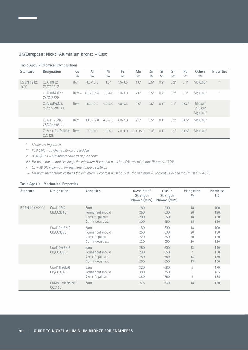
UK/European: Nickel Aluminium Bronze - Cast
Table App9 - Chemical Compositions
Standard Designation Cu %
Al %
Ni %
Fe %
Mn %
Zn %
Si %
Sn %
Pb %
Others%
Impurities
BS EN 1982: 2008
CuAl10Fe2 CB/CC331G
Rem 8.5-10.5 1.5* 1.5-3.5 1.0* 0.5* 0.2* 0.2* 0.1* Mg 0.05* **
CuAl10Ni3Fe2 CB/CC332G
Rem~ 8.5-10.5# 1.5-4.0 1.0-3.0 2.0* 0.5* 0.2* 0.2* 0.1* Mg 0.05* **
CuAl10Fe5Ni5 CB/CC333G ##
Rem 8.5-10.5 4.0-6.0 4.0-5.5 3.0* 0.5* 0.1* 0.1* 0.03* Bi 0.01* Cr 0.05*Mg 0.05*
CuAl11Fe6Ni6 CB/CC334G ~~
Rem 10.0-12.0 4.0-7.5 4.0-7.0 2.5* 0.5* 0.1* 0.2* 0.05* Mg 0.05*
CuMn11Al8Fe3Ni3 CC212E
Rem 7.0-9.0 1.5-4.5 2.0-4.0 8.0-15.0 1.0* 0.1* 0.5* 0.05* Mg 0.05*
* Maximum impurities
** Pb 0.03% max when castings are welded
# Al% <(8.2 + 0.5Ni%) for seawater applications
## For permanent mould castings the minimum Fe content must be 3.0% and minimum Ni content 3.7%
~ Cu = 88.5% maximum for permanent mould castings
~~ For permanent mould castings the minimum Fe content must be 3.0%, the minimum Al content 9.0% and maximum Cu 84.5%.
Table App10 - Mechanical Properties
Standard Designation Condition 0.2% Proof Strength
N/mm² (MPa)
Tensile Strength
N/mm² (MPa)
Elongation %
Hardness HB
BS EN 1982:2008 CuAl10Fe2 CB/CC331G
Sand Permanent mould Centrifugal cast Continuous cast
180 250 200 200
500 600 550 550
18 20 18 15
100 130 130 130
CuAl10Ni3Fe2 CB/CC332G
Sand Permanent mould Centrifugal cast Continuous cast
180 250 220 220
500 600 550 550
18 20 20 20
100 130 120 120
CuAI10Fe5Ni5 CB/CC333G
Sand Permanent mould Centrifugal cast Continuous cast
250 280 280 280
600 650 650 650
13 7 13 13
140 150 150 150
CuAl11Fe6Ni6 CB/CC334G
Sand Permanent mould Centrifugal cast
320 380 380
680 750 750
5 5 5
170 185 185
CuMn11Al8Fe3Ni3 CC212E
Sand 275 630 18 150
90 | GUIDE TO NICKEL ALUMINIUM BRONZE FOR ENGINEERS
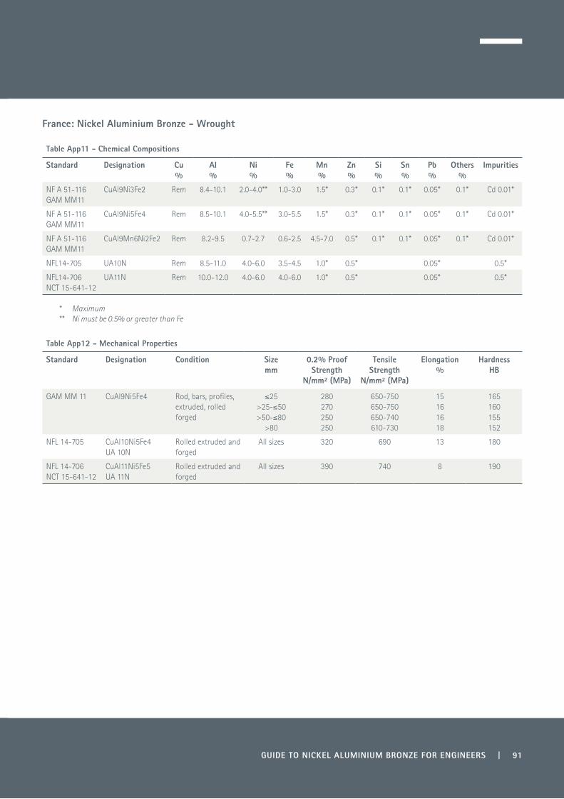
France: Nickel Aluminium Bronze - Wrought
Table App11 - Chemical Compositions
Standard Designation Cu %
Al %
Ni %
Fe %
Mn %
Zn %
Si %
Sn %
Pb %
Others %
Impurities
NF A 51-116 GAM MM11
CuAl9Ni3Fe2 Rem 8.4-10.1 2.0-4.0** 1.0-3.0 1.5* 0.3* 0.1* 0.1* 0.05* 0.1* Cd 0.01*
NF A 51-116 GAM MM11
CuAl9Ni5Fe4 Rem 8.5-10.1 4.0-5.5** 3.0-5.5 1.5* 0.3* 0.1* 0.1* 0.05* 0.1* Cd 0.01*
NF A 51-116 GAM MM11
CuAl9Mn6Ni2Fe2 Rem 8.2-9.5 0.7-2.7 0.6-2.5 4.5-7.0 0.5* 0.1* 0.1* 0.05* 0.1* Cd 0.01*
NFL14-705 UA10N Rem 8.5-11.0 4.0-6.0 3.5-4.5 1.0* 0.5* 0.05* 0.5*
NFL14-706 NCT 15-641-12
UA11N Rem 10.0-12.0 4.0-6.0 4.0-6.0 1.0* 0.5* 0.05* 0.5*
* Maximum** Ni must be 0.5% or greater than Fe
Table App12 - Mechanical Properties
Standard Designation Condition Size mm
0.2% Proof Strength
N/mm² (MPa)
Tensile Strength
N/mm² (MPa)
Elongation %
Hardness HB
GAM MM 11 CuAl9Ni5Fe4 Rod, bars, profiles, extruded, rolled forged
≤25 >25-≤50 >50-≤80
>80
280 270 250 250
650-750 650-750 650-740 610-730
1516 1618
165 160 155152
NFL 14-705 CuAl10Ni5Fe4 UA 10N
Rolled extruded and forged
All sizes 320 690 13 180
NFL 14-706 NCT 15-641-12
CuAl11Ni5Fe5 UA 11N
Rolled extruded and forged
All sizes 390 740 8 190
GUIDE TO NICKEL ALUMINIUM BRONZE FOR ENGINEERS | 91

92 | GUIDE TO NICKEL ALUMINIUM BRONZE FOR ENGINEERS
France: Nickel Aluminium Bronze - Cast
Table App13 - Chemical Compositions
Standard Designation Cu %
Al %
Ni %
Fe %
Mn %
Zn %
Si %
Sn %
Pb %
Others %
Impurities
GAM MM12 CuAl12Ni5Fe5 Rem 11.0-12.0 4.0-6.0 3.0-6.0 1.5* 0.5* 0.2* 0.2* 0.05* 0.8*
CuAl9Ni5Fe4 Rem 8.5-10.0 4.0-5.5 3.0-5.0 1.5* 0.3* 0.1* 0.1* 0.05* Cd 0.01*
NF A 53-709 CuAl10Fe5Ni5 Rem 8.5-10.5 4.0-6.0 4.0-5.5 2.5* 0.5* 0.1* 0.1* 0.03*
NF A 53-709 CuAl12Fe5Ni5 Rem 11.0-12.0 4.0-6.0 3.0-6.0 1.5* 0.5* 0.2* 0.2* 0.05*
* Maximum
Table App14 - Mechanical Properties
Standard Designation Condition 0.2% Proof Strength
N/mm² (MPa)
Tensile Strength
N/mm² (MPa)
Elongation %
Hardness HB
GAM MM12 CuAl9Ni5Fe4 Centrifugal and continuous cast
280 680 15 155
NFA 53-709 CuAl12Fe5Ni5 Y70Y80
390 400
780 750
8 7
215
NFA 53-709 CuAl10Fe5Ni5 Y80 300 650 15

GUIDE TO NICKEL ALUMINIUM BRONZE FOR ENGINEERS | 93
Germany: Nickel Aluminium Bronze - Wrought
Table App15 - Chemical Compositions
Standard Designation Cu %
Al %
Ni %
Fe %
Mn %
Zn %
Si %
Sn %
Pb %
Impurities
DIN 17665 WN 2.0971
CuAl9Ni3Fe2 Rem 8.0-9.5 1.5-4.0 1.0-3.0 2.5* 0.2* 0.1* 0.2* 0.05* 0.3*
DIN 17665 WN 2.0936
CuAl10Fe3Mn2 Rem 8.5-11.0 1.0* 2.0-4.0 1.5-3.5 0.5* 0.05* 0.3*
DIN 17665 WN 2.0966
CuAl10Ni5Fe4 Rem 8.5-11.0 4.0-6.0 2.0-5.0 1.5* 0.5* 0.05* 0.3*
DIN 17665 WN 2.0978
CuAl11Ni6Fe5 Rem 10.5-12.5 5.0-7.5 4.8-7.3 1.5* 0.5* 0.05* 0.3*
WL 2.0958 CuAl8Mn Rem 7.0-9.0 1.0-2.0 1.5* 5.0-6.5 0.3* 0.1* 0.1*
WL 2.0967 CuAl9Ni7 Rem 9.0-9.5 6.7-7.3 0.9-1.3 0.8-1.2 0.3* 0.1*
* Maximum

Germany: Nickel Aluminium Bronze - Wrought
Table App16 - Mechanical Properties
Standard Form Designation Condition Size mm
0.2% Proof Strength
N/mm² (MPa)
Tensile Strength
N/mm² (MPa)
Elongation %
Hardness HB
DIN 17678 Hand forgings CuAl10Ni5Fe4WN 2.0966CuAl11Ni6Fe5WN 2.0978
F72F70F74F74F80F80
≤80>80≤80>80≤80>80
360340420410570540
720700740740800800
12155444
175170205205215215
DIN 17672 Rod and bar CuAl10Fe WN 2.0936CuAl10Ni5Fe4 WN 2.0966CuAl11Ni6Fe5 WN 2.0978
F59 F69F64 F74F73 F83
12-8012-5012-8012-5012-8012-50
250 340270 390440 590
590 690640 740730 830
12 715 145
150 180180 195210 240
DIN 17670 Plate CuAl9Ni3Fe2 WN 2.0971
CuAl10Ni5Fe4 WN 2.0966
F49 H105F62
H150F63
H160
3-153-153-153-153-153-15
180
290
270
490
620
630
25
15
8
100-140
140
150
DIN 17671 Tube CuAl10FeMn2 WN 2.0936CuAl11Ni6Fe5 WN 2.0978
F64
F69
Wall thickness 4-8
Wall thickness 2-5
290
290
640
690
10
15
165
140
Specification Form Designation Size mm
0.2% Proof Strength
N/mm² (MPa)
Tensile Strength
N/mm² (MPa)
Elongation %
Hardness HB
Impact Joules
WL 2.0958 * Round, square and hexagonal bar
CuAl8Mn ≥10-≤25 >25-≤80
290 240
590 540
20 22
140 135
4543
Round bar >80 220 540 23 130 38
Specification Form Designation Size mm
0.2% Proof Strength
N/mm² (MPa)
Tensile Strength
N/mm² (MPa)
Elongation %
Hardness HB
Impact Joules
WL 2.0967* Bars and forgings CuAl9Ni7 ≥10-≤25 >25-≤80
>80
300 280260
600 600570
12 1518
150 145140
≥10 ≥9≥8
* Relative Magnetic Permeability ≤ 1.03µr
94 | GUIDE TO NICKEL ALUMINIUM BRONZE FOR ENGINEERS

Germany: Nickel Aluminium Bronze - Cast
Table App17 - Chemical Compositions
StandardDIN 1714
Designation Cu %
Al %
Ni %
Fe %
Mn %
Zn %
Si %
Sn %
Pb %
Others %
Impurities
WN 2.0940 G CuAl10Fe Rem 8.5-11.0 3.0* 2.0-4.0 1.0* 0.5* 0.2* 0.3* 0.2* 1.0*
WN 2.0970 G CuAl9Ni Rem 8.5-10.0 1.5- 4.0 1.0-3.0 2.5 0.2* 0.1* 0.2* 0.05* Mg 0.05* 0.4*
WN 2.0975 G CuAl10Ni Rem 8.5-11.0 4.0-6.5 3.5-5.5 3.0* 0.5* 0.1* 0.2* 0.05* Mg 0.05* 0.4*
* Maximum
Table App18 - Mechanical Properties
StandardDIN 1714
Designation Form 0.2% Proof Strength
N/mm² (MPa)
Tensile Strength
N/mm² (MPa)
Elongation %
Hardness HB
WN 2.0940 G CuAl10Fe Sand cast 180 500 15 115
Die cast 200 550 25 115
WN 2.0970 G CuAl9Ni Sand cast 200 500 20 110
Die cast 250 600 20 120
WN 2.0975 G CuAl10Ni Sand cast 270 600 12 140
Die cast 330 600 12 150
Centrifugal cast 300 700 13 160
Continuous cast 300 700 13 160
GUIDE TO NICKEL ALUMINIUM BRONZE FOR ENGINEERS | 95

96 | GUIDE TO NICKEL ALUMINIUM BRONZE FOR ENGINEERS
USA: Nickel Aluminium Bronze - Wrought
Table App19 - Chemical Compositions
Standard Designation Cu** %
Al %
Ni## %
Fe %
Mn %
Zn %
Si %
Sn %
Pb %
Others %
ASTM B150 AMS 4640 MIL 16166
C63000 Rem 9.0-11.0 4.0-5.5 2.0-4.0 1.5* 0.3* 0.25* 0.20*
ASTM B150 MIL B 24059 QQC 465B
C63200 Rem 8.7-9.5 4.0-4.8 3.5-4.3# 1.2-2.0 0.1* 0.02*
AMS 4590 C63020 74.5 min 10.0-11.0 4.2-6.0 4.0-5.5 1.5* 0.3* 0.15* 0.25* 0.03* 0.2* Co 0.05* Cr
* Maximum** Cu including Ag# Fe must be lower than Ni## Ni including Co
Table App20 - Mechanical Properties
Standard Form Designation Size mm
0.5% Proof Strength *
N/mm2 (MPa)
Tensile Strength
N/mm² (MPa)
Elongation %
Hardness HB
AMS 4640 Rounds, hexagonal and octagonal bar, rods and shapes
Flats, squares and tubes
C63000 ≤25.4 >25.4-≤50.8 >50.8-≤76.2 >76.2-≤127
≤25.4 >25.4-≤76.2
>76.2
469 414 379 345 359 345 330
758 758 724 689 689 655621
10 10 10 10 10 10 10
201-248 201-248 187-241 187-241 187-241 187-241 183-241
AMS 4590 Extruded bar, rods and tubes
C63020 ≤25.4 >25.4-<50.8 ≥50.8-≤101.6
689 655 621
931 896 896
6 6 6
≥26 HRC ≥26 HRC ≥26 HRC
ASTM B150QQ C 465B
Drawn and stress relieved rod
Bar Shapes
Drawn and stress relieved rod
Quench hardened and temper annealed
C63000 HR50
M20, M30, 020, 025, 030, HR50
HR50 High strength
TQ50
>12-≤25 >25-≤50 >50-≤80
>80-≤100 >100 all sizes
≤25 >25-≤50 >50-≤80
>80-≤130
345 310 295
295 275295
470 415 380
345
690 620 585
585 550 585
760 760 725
690
5 6 10
10 12 10
10 10 10
10
ASTM B150QQ C 465B
Quench hardened and temper annealed
C63200 TQ50 TQ 55
Shapes all sizes
≤80 >80-≤130
>130
345 310 275 275
620 620 620 620
15 15 15 15
MIL B 24059
Superseded
Bar C63000 ≤25.4 >25.4-≤75 >75-≤127
>127
345 331 310 255
620 620 620 620
18 18 18 18
ASTM B171
Superseded,
Withdrawn
Plate C63000 ≤50 >50-≤100 >100-≤140
250 230 205
620 585 550
10 1010
* For uniformity with other Table Apps, US yield strength values have been relabelled as proof strength

GUIDE TO NICKEL ALUMINIUM BRONZE FOR ENGINEERS | 97
USA: Nickel Aluminium Bronze - Cast
Table App21 - Chemical Compositions
Standard Designation Cu**%
Al%
Ni#%
Fe%
Mn%
Zn%
Si%
Sn%
Pb%
ASTM B 505 C95400C95500C95700C95800
83.0 min76.0 min71.0 min79.0 min
10.0-11.510.0-11.57.0-8.08.5-9.5
1.5*3.0-5.51.5-3.04.0-5.0
3.0-5.03.0-5.02.0-4.03.5-4.5
0.5*3.5*
11.0-14.00.8-1.5
0.1*0.1* 0.1*
0.03*0.05*
ASTM B 763 C95400C95500C95800
83.0 min76.0 min79.0 min
10.0-11.510.0-11.58.5-9.5
1.5*3.0-5.54.0-5.0
3.0-5.03.0-5.03.5-4.5
0.5*3.5*
0.8-1.5 0.1* 0.1* 0.05*
ASTM B 806 C95400C95500C95800
83.0 min76.0 min79.0 min
10.0-11.510.0-11.58.5-9.5
1.5*3.0-5.54.0-5.0
3.0-5.03.0-5.03.5-4.5
0.5*3.5*
0.8-1.5 0.1* 0.1* 0.05*
Specification Designation Cu %
Al %
Ni# %
Fe %
Mn %
Zn %
Si %
Sn %
Pb %
Others %
AMS 4880 C95510 78.0 min** 9.7-10.9 4.5-5.5 2.0-3.5 1.5* 0.3* 0.2*
AMS 4881 C95520 74.5 min*** 10.5-11.5 4.2-6.0 4.0-5.5 1.5* 0.3* 0.15* 0.25* 0.03* 0.2* Co0.05* Cr
* Maximum** Cu + sum of named elements = 99.8 min*** Cu = sum of named elements = 99.5 min# Nickel including cobalt
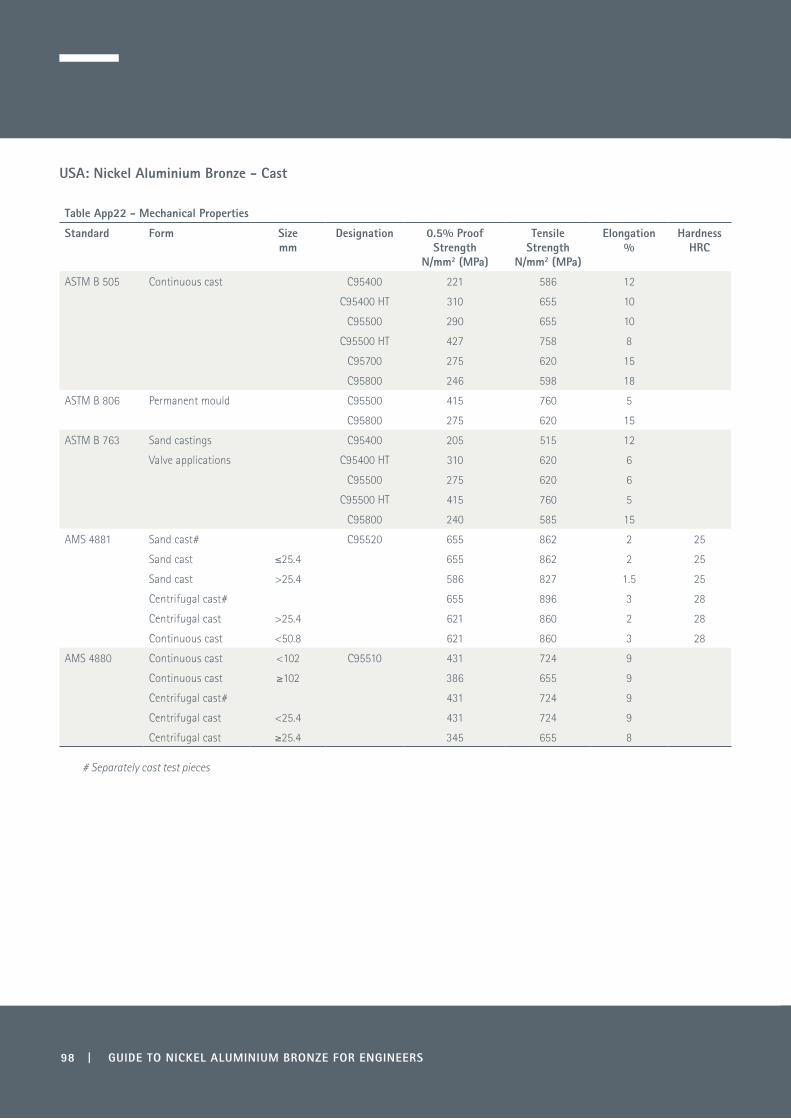
98 | GUIDE TO NICKEL ALUMINIUM BRONZE FOR ENGINEERS
USA: Nickel Aluminium Bronze - Cast
Table App22 - Mechanical Properties
Standard Form Sizemm
Designation 0.5% Proof Strength
N/mm2 (MPa)
Tensile Strength
N/mm2 (MPa)
Elongation%
HardnessHRC
ASTM B 505 Continuous cast C95400 221 586 12
C95400 HT 310 655 10
C95500 290 655 10
C95500 HT 427 758 8
C95700 275 620 15
C95800 246 598 18
ASTM B 806 Permanent mould C95500 415 760 5
C95800 275 620 15
ASTM B 763 Sand castings C95400 205 515 12
Valve applications C95400 HT 310 620 6
C95500 275 620 6
C95500 HT 415 760 5
C95800 240 585 15
AMS 4881 Sand cast# C95520 655 862 2 25
Sand cast ≤25.4 655 862 2 25
Sand cast >25.4 586 827 1.5 25
Centrifugal cast# 655 896 3 28
Centrifugal cast >25.4 621 860 2 28
Continuous cast <50.8 621 860 3 28
AMS 4880 Continuous cast <102 C95510 431 724 9
Continuous cast ≥102 386 655 9
Centrifugal cast# 431 724 9
Centrifugal cast <25.4 431 724 9
Centrifugal cast ≥25.4 345 655 8
# Separately cast test pieces

GUIDE TO NICKEL ALUMINIUM BRONZE FOR ENGINEERS | 99
Notes

Copy
right
© 2
016.
Cop
per D
evel
opm
ent A
ssoc
iatio
n
Copper Development Association5 Grovelands Business Centre
Boundary WayHemel Hempstead, HP2 7TE
UK