guide to instantaneous selectivity circuit breaker ...€¦ · circuit breaker mechanisms employ...
TRANSCRIPT
—Guide to Instantaneous SelectivityCircuit Breaker Engineering Reference

This page left intentionally blank
01 Introduction02 Assumptions02 Considerations and Cautionary Notes Regarding Implementation
of Instantaneous Selectivity02 How to Find and Read Values in the Tables02 Systems with More than Two Circuit Breakers03 Through Transformer Selectivity03 Accounting for X/R Ratios Greater than Test Ratios04 Circuit Breaker Types
04 ANSI/UL 1066 Circuit Breakers with Fully Adjustable Trips04 UL 489 Circuit Breakers with Fully Adjustable Trips05 Molded Case Circuit Breakers (MCCB)
05 ArcWatch with Instantaneous Zone Selective Interlocking (I-ZSI) and Waveform Recognition (WFR) Technology
06 EntelliGuard Series Trip Units in ANSI, Power Break II, and Molded Case Circuit Breakers
09 Selectivity with EntelliGuard TU Trip Units in ANSI, Power Break II, and Molded Case Circuit Breakers
10 Selectivity with Record Plus FE and FG11 Selectivity with Tmax XT15 ArcWatch I-ZSI on EntelliGuard TU Trip Units in ANSI WavePro Circuit Breakers16 ArcWatch I-ZSI on EntelliGuard TU Trip Units in ANSI/UL 1066 EntelliGuard G
Circuit Breakers17 ArcWatch I-ZSI on EntelliGuard TU Trip Units in UL489 EntelliGuard G
Circuit Breakers18 ArcWatch I-ZSI on Spectra microEntelliGuard Molded Case Circuit
Breakers (MCCBs)
Spectra Series® Switchboards
EntelliGuard® G
EntelliGuard® TU
microEntelliGuard™
Record Plus® Circuit Breakers
WavePro™ Circuit Breakers
ArcWatch™
Tmax® XT
Emax® 2
This document is based on information available at the time of its publication. While efforts have been made to ensure accuracy, the information contained herein does not cover all details or variations in hardware and software, nor does it provide for every possible contingency in connection with installation, operation, and maintenance. Features may be described herein that are not present in all hardware and software systems. ABB assumes no obligation of notice to holders of this document with respect to changes subsequently made. ABB makes no representation or warranty, expressed, implied, or statutory, with respect to, and assumes no responsibility for the accuracy, completeness, sufficiency, or usefulness of the information contained herein. No warrantees of merchantability or fitness for purpose shall apply.
Contact your local sales office if further information is required concerning any aspect of system operation or maintenance.
—Table of Contents
—Trademarks
—Warranty
Scan this QR code to learn more about Selective Coordination.
ii G U I D E TO I N S TA NTA N EO U S S E LEC TI V IT Y CI R CU IT B R E A K ER EN G I N EER I N G R EFER EN CE D E T-76 0 G

01 G U I D E TO I N S TA NTA N EO U S S E LEC TI V IT Y CI R CU IT B R E A K ER EN G I N EER I N G R EFER EN CE D E T-76 0 G
ArcWatch is a set of ABB technologies, WaveForm Recognition (WFR) and Instantaneous Zone Selective Interlocking (I-ZSI) which, when used in combination with one another allow system design that does not require compromise between instantaneous protection from arcing faults and full (.01 Second) selective coordination. Using these technologies, ArcWatch can reduce incident energy to less than 8 cal/cm2 in.
WFR provides ArcWatch protection and coordination between a circuit breaker equipped with an EntelliGuard family trip unit and a downstream current limiting device (Record Plus, Spectra, TEY-type MCCBs for example). WFR allows EntelliGuard family trip units to recognize the action of a current limiting device downstream. Faults that are already being acted upon by a downstream limiter do not require action; faults that aren’t require action. WFR directs the selective response, depending on the location of the fault.
I-ZSI is used to provide ArcWatch protection and coordination between multiple circuit breakers equipped with EntelliGuard family trip units. A simple, ultra-fast acting signal, transmitted between electronic trip units, communicates the fault location, determines which circuit breaker will respond to a fault, and which circuit breakers remain closed.
ArcWatch technology embedded in specific low-voltage ABB trip units and circuit breakers allows circuit breakers to be set for maximum arc flash protection without sacrificing selective coordination. Setting the instantaneous pick-up value sufficiently below the predicted arcing current permits the circuit breaker to clear arcing faults using the circuit breaker’s fastest speed. Traditionally, lower pick-up settings lead to reduced selective coordination. ArcWatch solves this dilemma by maintaining selective operation in the instantaneous region even when the time current curves overlap.
These technologies with full-time, always on arc flash mitigation and full selective coordination are ArcWatch.
The following tables list the instantaneous selectivity capability of various ABB circuit breakers. In many cases, selectivity may exceed the selectivity determined by traditional time-current curve analysis. The traditional time-current curves, plotted in Figure 1, demonstrate that the 100A and 1600A circuit breakers shown are fully selective up to ~21,500A RMS. However, other analytical techniques and high current testing have demonstrated that these two circuit breakers are selective to a much higher value, 65,000A. The higher values available with many overcurrent devices will be shown on the tables in this reference publication, as well as some values determined by traditional curve overlay.
—Introduction
Circuit breaker mechanisms employ multiple means to open and latch contacts. Some of the mechanisms are very sensitive to instantaneous peak currents. Other mechanisms may be more sensitive to energy, rate of change of current, etc. Some techniques, like ArcWatch, take into account waveform shape and many use combinations of these mechanisms. The different operating mechanisms used and their respective interactions are considered when analyzing system selectivity. Traditional time-current curve based coordination studies provide a very conservative analytical method for determining selectivity and ignore the impact of the various circuit breaker operating mechanism designs.
The selectivity tables in this publication were derived through rigorous analytical techniques, extensive testing, and Six Sigma methodology. The testing was performed using a protocol similar to that described in UL 489 (Standard for Molded Case Circuit Breakers) for series ratings. Testing and analysis was performed for a range of fault magnitudes, closing angles and X/R ratios.
—Figure 1: How tables are derived
DET-760E Guide to Instantaneous Selectivity
© 2018 General Electric All Rights Reserved 1
INTRODUCTION ArcWatch is a set of GE Technologies, WaveForm Recognition (WFR) and Instantaneous Zone Selective Interlocking (I-ZSI) which, when used in combination with one another allow system design that does not require compromise between instantaneous protection from arcing faults and full (.01 Second) selective coordination. Using these technologies, ArcWatch can reduce incident energy to less than 8 cal/cm2 in. WFR provides ArcWatch protection and coordination between a circuit breaker equipped with an EntelliGuard family trip unit and a downstream current limiting device (Record Plus, Spectra, TEY-type MCCBs for example). WFR allows EntelliGuard family trip units to recognize the action of a current limiting device downstream. Faults that are already being acted upon by a downstream limiter do not require action; faults that aren’t require action. WFR directs the selective response, depending on the location of the fault. I-ZSI is used to provide ArcWatch protection and coordination between multiple circuit breakers equipped with EntelliGuard family trip units. A simple, ultra-fast acting signal, transmitted between electronic trip units, communicates the fault location, determines which circuit breaker will respond to a fault, and which circuit breakers remain closed. ArcWatch technology embedded in specific low-voltage GE trip units and circuit breakers allows circuit breakers to be set for maximum arc flash protection without sacrificing selective coordination. Setting the instantaneous pick-up value sufficiently below the predicted arcing current permits the circuit breaker to clear arcing faults using the circuit breaker’s fastest speed. Traditionally, lower pick-up settings lead to reduced selective coordination. ArcWatch solves this dilemma by maintaining selective operation in the instantaneous region even when the time current curves overlap. These technologies with full-time, always on arc flash mitigation and full selective coordination are ArcWatch.
The following tables list the instantaneous selectivity capability of various GE circuit breakers. In many cases, selectivity may exceed the selectivity determined by traditional time-current curve analysis. The traditional time-current curves, plotted in Figure 1, demonstrate that the 100A and 1600A circuit breakers shown are fully selective up to ~21,500A RMS. However, other analytical techniques and high current testing have demonstrated that these two circuit breakers are selective to a much higher value, 65,000A. The higher values available with many overcurrent devices will be shown on the tables in this reference publication, as well as some values determined by traditional curve overlay.
Figure 1: How tables are derived
Circuit breaker mechanisms employ multiple means to open and latch contacts. Some of the mechanisms are very sensitive to instantaneous peak currents. Other mechanisms may be more sensitive to energy, rate of change of current, etc. Some techniques, like ArcWatch, take into account waveform shape and many use combinations of these mechanisms. The different operating mechanisms used and their respective interactions are considered when analyzing system selectivity. Traditional time-current curve based coordination studies provide a very conservative analytical method for determining selectivity and ignore the impact of the various circuit breaker operating mechanism designs.
The selectivity tables in this publication were derived through rigorous analytical techniques, extensive testing, and Six Sigma methodology. The testing was performed using a protocol similar to that described in UL 489 (Standard for Molded Case Circuit Breakers) for series ratings. Testing and analysis was performed for a range of fault magnitudes, closing angles and X/R ratios.
Entelliguard TUSensor = 1600Plug = 1600Cur Set = 1 (1600A)LT Curve = Thermal I(^t)STPU = 9 (1400A)ST Delay = 8INST = 15 (2400A)

02 G U I D E TO I N S TA NTA N EO U S S E LEC TI V IT Y CI R CU IT B R E A K ER EN G I N EER I N G R EFER EN CE D E T-76 0 G
ASSUMPTIONS• Fault values are expressed in 60 Hz RMS.• Selectivity short circuit values are valid at the voltage described and any lower
voltage. Selectivity at voltages higher than specifically noted is not implied in these tables.
• Selectivity values for paired circuit breakers are valid for X/R ratios equal to, or less than, those for which the circuit breakers were tested or analyzed. A fault X/R ratio higher than the test X/R ratio will require that the selectivity be de-rated by the ratio of the prospective peak currents. A table of X/R ratios, Power Factors, and expected peak currents is provided (see Table 1). These de-rating methods are the same as those used to de-rate the interrupting rating of any overcurrent protection device whose test X/R ratio is less than the X/R ratio of the available fault current where the device is applied.
• For devices equipped with any of the EntelliGuard series of trip units, the EntelliGuard TU trip unit (ETU,) or the microEntelliGuard Trip Unit (MET,) selectivity is determined by the instantaneous settings on the trip unit. Table 3 illustrates selectivity levels possible using ETU and MET. Tables 6 through 11 illustrate enhanced selectivity possible using the I-ZSI capabilities of the EntellliGuard series trip units.
• For devices not equipped with ETU or MET, the values in the tables represent instantaneous selectivity based on both the upstream and downstream circuit breaker Instantaneous Overcurrent (IOC) being set at the highest possible setting. Where the downstream circuit breaker has an adjustable trip, the setting may be adjusted lower without adverse impact on selectivity. (Unless otherwise indicated, the upstream breaker IOC setting must remain at maximum to achieve the listed selectivity).
CONSIDERATIONS AND CAUTIONARY NOTES REGARDING IMPLEMENTATION OF INSTANTANEOUS SELECTIVITYMost industry standards, and good engineering practice, indicate that selectivity is desirable in power distribution systems to maximize system reliability. System designers must weigh selectivity needs against other important system considerations, such as safety, operational reliability, feasibility, efficiency, cost, and size. The National Electrical Code (NEC) defines minimum performance requirements for construction. Designers should consider other factors that may or may not be addressed by the NEC. They should be aware that systems designed for high levels of selectivity may lead to higher arc flash energy, reduced operator and maintenance safety, higher installation costs, and larger equipment or conductors. The use of ArcWatch and other technologies help balance the compromises between arc flash risk and selectivity, the consequences of these risks should be understood.
Traditional time-current curve based analysis must still be used to make sure that long time, short time phase overcurrent and ground fault protection devices are selectively coordinated.
These tables provide guidance on circuit breaker selectivity where the instantaneous clearing times shown on traditional-time-current curves overlap.
HOW TO FIND AND READ VALUES IN THE TABLESBefore using these tables, the user should have the system one-line diagram, complete with system voltages and available fault currents. The capability for instantaneous selectivity of a particular circuit breaker pair may be dependent on trip setting, rating plug, the circuit breaker’s sensor, or the circuit breaker’s frame size. The tables will indicate which parameter in the device drives its selective capability.
The Selectivity Tables are organized with upstream devices across the top of the tables (in boldface type), and downstream devices in columns on the left.
In tables 3 and 3a, the column titled “Instantaneous Setting Must Be Greater Than” shows the minimum instantaneous pickup, in amps, (on the upstream device) that will provide the selectivity shown with the corresponding downstream device. Table 4 illustrates the maximum possible pickup settings for typical upstream devices equipped with the ETU or MET.
Tables 5, 5a and 5b, arranged the same way, shows the selectivity of devices not equipped with ETU or MET, including current limiting circuit breakers. The value at the intersection of a row and column defines the maximum instantaneous current selectivity capability of the paired devices.
Tables 6 through 11 are also arranged with upstream devices across the top of the tables and downstream devices in the left column. The intersection of a row and column define the maximum possible selectivity of that pair of devices using ArcWatch I-ZSI.
For combinations not shown in the tables or where a table value is blank, the selectivity between the pair can be determined by curve overlay.
Often selectivity may be improved by using a larger upstream device or a circuit breaker with greater adjustability. Downstream selectivity may be improved by using a device with greater current limiting characteristics.
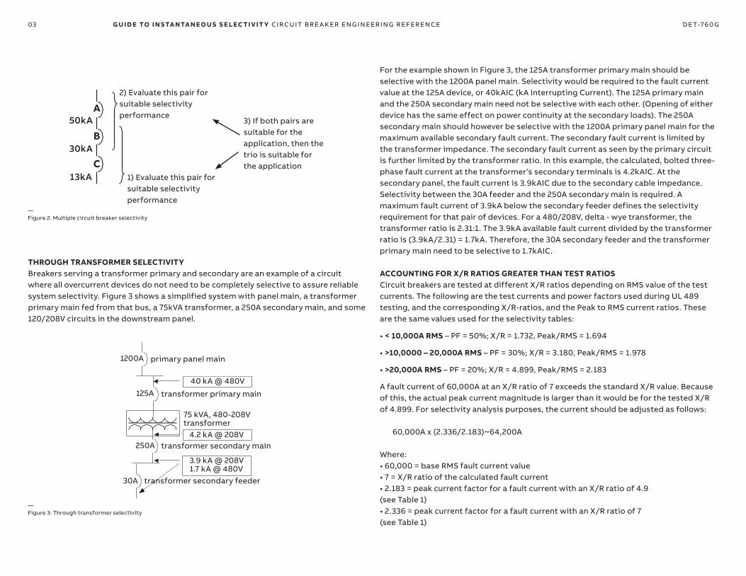
SYSTEMS WITH MORE THAN TWO CIRCUIT BREAKERSThe analysis used to produce the tables allows three or more devices to be combined. Figure 2 represents a system composed of three circuit breakers defined as devices A, B, and C. The devices are applied at three different fault current values. Circuit breaker A and circuit breaker B need to be selective to 30kA, circuit breaker B and circuit breaker C need to be selective to 13kA. If these two requirements are fulfilled then circuit breakers A and C will also be selective. Note that the fault current value at the first circuit breaker is important to determine the short circuit rating required for that device; however, it is the available fault current at the downstream circuit breaker that determines the selectivity need.
03 G U I D E TO I N S TA NTA N EO U S S E LEC TI V IT Y CI R CU IT B R E A K ER EN G I N EER I N G R EFER EN CE D E T-76 0 G
THROUGH TRANSFORMER SELECTIVITYBreakers serving a transformer primary and secondary are an example of a circuit where all overcurrent devices do not need to be completely selective to assure reliable system selectivity. Figure 3 shows a simplified system with panel main, a transformer primary main fed from that bus, a 75kVA transformer, a 250A secondary main, and some 120/208V circuits in the downstream panel.
For the example shown in Figure 3, the 125A transformer primary main should be selective with the 1200A panel main. Selectivity would be required to the fault current value at the 125A device, or 40kAIC (kA Interrupting Current). The 125A primary main and the 250A secondary main need not be selective with each other. (Opening of either device has the same effect on power continuity at the secondary loads). The 250A secondary main should however be selective with the 1200A primary panel main for the maximum available secondary fault current. The secondary fault current is limited by the transformer impedance. The secondary fault current as seen by the primary circuit is further limited by the transformer ratio. In this example, the calculated, bolted three-phase fault current at the transformer’s secondary terminals is 4.2kAIC. At the secondary panel, the fault current is 3.9kAIC due to the secondary cable impedance. Selectivity between the 30A feeder and the 250A secondary main is required. A maximum fault current of 3.9kA below the secondary feeder defines the selectivity requirement for that pair of devices. For a 480/208V, delta - wye transformer, the transformer ratio is 2.31:1. The 3.9kA available fault current divided by the transformer ratio is (3.9kA/2.31) = 1.7kA. Therefore, the 30A secondary feeder and the transformer primary main need to be selective to 1.7kAIC.
ACCOUNTING FOR X/R RATIOS GREATER THAN TEST RATIOSCircuit breakers are tested at different X/R ratios depending on RMS value of the test currents. The following are the test currents and power factors used during UL 489 testing, and the corresponding X/R-ratios, and the Peak to RMS current ratios. These are the same values used for the selectivity tables:
• < 10,000A RMS – PF = 50%; X/R = 1.732, Peak/RMS = 1.694
• >10,0000 – 20,000A RMS – PF = 30%; X/R = 3.180, Peak/RMS = 1.978
• >20,000A RMS – PF = 20%; X/R = 4.899, Peak/RMS = 2.183
A fault current of 60,000A at an X/R ratio of 7 exceeds the standard X/R value. Because of this, the actual peak current magnitude is larger than it would be for the tested X/R of 4.899. For selectivity analysis purposes, the current should be adjusted as follows:
60,000A x (2.336/2.183)~64,200A
Where:• 60,000 = base RMS fault current value• 7 = X/R ratio of the calculated fault current• 2.183 = peak current factor for a fault current with an X/R ratio of 4.9 (see Table 1)• 2.336 = peak current factor for a fault current with an X/R ratio of 7 (see Table 1)
—Figure 3: Through transformer selectivity
—Figure 2: Multiple circuit breaker selectivity
DET-760E Guide to Instantaneous Selectivity
© 2018 General Electric All Rights Reserved 3
short circuit rating required for that device; however, it is the available fault current at the downstream circuit breaker that determines the selectivity need.
Figure 2: Multiple circuit breaker selectivity
THROUGH TRANSFORMER SELECTIVITY
Breakers serving a transformer primary and secondary are an example of a circuit where all overcurrent devices do not need to be completely selective to assure reliable system selectivity. Figure 3 shows a simplified system with panel main, a transformer primary main fed from that bus, a 75kVA transformer, a 250A secondary main, and some 120/208V circuits in the downstream panel.
Figure 3: Through transformer selectivity
For the example shown in Figure 3, the 125A transformer primary main should be selective with the 1200A panel main. Selectivity would be required to the fault current value at the 125A device, or 40kAIC (kA Interrupting Current). The 125A primary main and the 250A secondary main need not be selective with each other. (Opening of either device has the same effect on power continuity at the
secondary loads). The 250A secondary main should however be selective with the 1200A primary panel main for the maximum available secondary fault current. The secondary fault current is limited by the transformer impedance. The secondary fault current as seen by the primary circuit is further limited by the transformer ratio. In this example, the calculated, bolted three-phase fault current at the transformer’s secondary terminals is 4.2kAIC. At the secondary panel, the fault current is 3.9kAIC due to the secondary cable impedance. Selectivity between the 30A feeder and the 250A secondary main is required. A maximum fault current of 3.9kA below the secondary feeder defines the selectivity requirement for that pair of devices. For a 480/208V, delta - wye transformer, the transformer ratio is 2.31:1. The 3.9kA available fault current divided by the transformer ratio is (3.9kA/2.31) = 1.7kA. Therefore, the 30A secondary feeder and the transformer primary main need to be selective to 1.7kAIC.
ACCOUNTING FOR X/R RATIOS GREATER THAN TEST RATIOS
Circuit breakers are tested at different X/R ratios depending on RMS value of the test currents. The following are the test currents and power factors used during UL 489 testing, and the corresponding X/R-ratios, and the Peak to RMS current ratios. These are the same values used for the selectivity tables:
< 10,000A RMS – PF = 50%; X/R = 1.732, Peak/RMS = 1.694
>10,0000 – 20,000A RMS – PF = 30%; X/R = 3.180, Peak/RMS = 1.978
>20,000A RMS – PF = 20%; X/R = 4.899, Peak/RMS = 2.183
A fault current of 60,000A at an X/R ratio of 7 exceeds the standard X/R value. Because of this, the actual peak current magnitude is larger than it would be for the tested X/R of 4.899. For selectivity analysis purposes, the current should be adjusted as follows:
60,000A x (2.336/2.183)~64,200A
Where:
60,000 = base RMS fault current value
7 = X/R ratio of the calculated fault current
2.183 = peak current factor for a fault current with an X/R ratio of 4.9 (see Table 1)
2.336 = peak current factor for a fault current with an X/R ratio of 7 (see Table 1)
2) Evaluate this pair for suitable selectivity performance
3) If both pairs are suitable for the application, then the trio is suitable for the application
1) Evaluate this pair for suitable selectivity performance
50kA
30kA
13kA
DET-760E Guide to Instantaneous Selectivity
© 2018 General Electric All Rights Reserved 3
short circuit rating required for that device; however, it is the available fault current at the downstream circuit breaker that determines the selectivity need.
Figure 2: Multiple circuit breaker selectivity
THROUGH TRANSFORMER SELECTIVITY
Breakers serving a transformer primary and secondary are an example of a circuit where all overcurrent devices do not need to be completely selective to assure reliable system selectivity. Figure 3 shows a simplified system with panel main, a transformer primary main fed from that bus, a 75kVA transformer, a 250A secondary main, and some 120/208V circuits in the downstream panel.
Figure 3: Through transformer selectivity
For the example shown in Figure 3, the 125A transformer primary main should be selective with the 1200A panel main. Selectivity would be required to the fault current value at the 125A device, or 40kAIC (kA Interrupting Current). The 125A primary main and the 250A secondary main need not be selective with each other. (Opening of either device has the same effect on power continuity at the
secondary loads). The 250A secondary main should however be selective with the 1200A primary panel main for the maximum available secondary fault current. The secondary fault current is limited by the transformer impedance. The secondary fault current as seen by the primary circuit is further limited by the transformer ratio. In this example, the calculated, bolted three-phase fault current at the transformer’s secondary terminals is 4.2kAIC. At the secondary panel, the fault current is 3.9kAIC due to the secondary cable impedance. Selectivity between the 30A feeder and the 250A secondary main is required. A maximum fault current of 3.9kA below the secondary feeder defines the selectivity requirement for that pair of devices. For a 480/208V, delta - wye transformer, the transformer ratio is 2.31:1. The 3.9kA available fault current divided by the transformer ratio is (3.9kA/2.31) = 1.7kA. Therefore, the 30A secondary feeder and the transformer primary main need to be selective to 1.7kAIC.
ACCOUNTING FOR X/R RATIOS GREATER THAN TEST RATIOS
Circuit breakers are tested at different X/R ratios depending on RMS value of the test currents. The following are the test currents and power factors used during UL 489 testing, and the corresponding X/R-ratios, and the Peak to RMS current ratios. These are the same values used for the selectivity tables:
< 10,000A RMS – PF = 50%; X/R = 1.732, Peak/RMS = 1.694
>10,0000 – 20,000A RMS – PF = 30%; X/R = 3.180, Peak/RMS = 1.978
>20,000A RMS – PF = 20%; X/R = 4.899, Peak/RMS = 2.183
A fault current of 60,000A at an X/R ratio of 7 exceeds the standard X/R value. Because of this, the actual peak current magnitude is larger than it would be for the tested X/R of 4.899. For selectivity analysis purposes, the current should be adjusted as follows:
60,000A x (2.336/2.183)~64,200A
Where:
60,000 = base RMS fault current value
7 = X/R ratio of the calculated fault current
2.183 = peak current factor for a fault current with an X/R ratio of 4.9 (see Table 1)
2.336 = peak current factor for a fault current with an X/R ratio of 7 (see Table 1)
transformer primary main
transformer secondary main
transformer secondary feeder
75 kVA, 480-208V transformer
primary panel main
40 kA @ 480V
4.2 kA @ 208V
3.9 kA @ 208V 1.7 kA @ 480V
1200A
125A
250A
30A
A
B
C

04 G U I D E TO I N S TA NTA N EO U S S E LEC TI V IT Y CI R CU IT B R E A K ER EN G I N EER I N G R EFER EN CE D E T-76 0 G
CIRCUIT BREAKER TYPESABB offers several types of circuit breakers with different adjustment and selectivity capabilities. They are broadly described in this section.
EntelliGuard® TU trip unit and Spectra RMS allow instantaneous trip to be adjusted as a multiple of the rating plug Ampacity. The maximum adjustment may be limited by the frame. For Record Plus and Spectra with microEntelliGuard, the instantaneous trip is adjusted as a multiple of the current sensor.
ANSI /UL 1066 Circuit Breakers with Fully Adjustable TripsANSI circuit breakers are those designed and tested to ANSI C37 standards. ABB ANSI devices are Emax 2, AKR, WavePro®, EntelliGuard and EntelliGuard G ANSI circuit breakers. They are generically called Low Voltage Power Circuit Breakers (LVPCBs), and are listed to UL 1066.
EntelliGuard G ANSI /UL 1066 circuit breakers are available with or without Instantaneous Overcurrent Protection. Some EntelliGuard G ANSI/UL 1066 circuit breakers are equipped with an Instantaneous “Override” at very high fault currents. These override-equipped circuit breakers are selective to the current level at which the override becomes active (85-100kA, depending on frame). This level is referred to as the “Withstand Rating” in the tables.
UL 489 Circuit Breakers with Fully Adjustable TripsInsulated Case Circuit Breakers (ICCBs) are listed to UL 489. The tables on pages 7-8 also include UL 489 listed Power Break II and EntelliGuard G circuit breakers with EntelliGuard TU trip units. These always include Long-Time, Short Time, and Instantaneous (LSI) protections, although a user may choose to not implement the S function.
Typically, any circuit breaker with adjustable short time pickup and delay allows for a higher instantaneous pickup adjustment. A higher instantaneous pickup may facilitate higher levels of instantaneous selectivity.
Selectivity limits for these circuit breakers are established based on withstand (EntelliGuard G UL489) or short circuit (Power Break II) ratings.
Test Ranges Power Factor X/R Ratio Maximum Peak4 24.9790 2.6635 19.9740 2.6256 16.6230 2.5897 14.2510 2.5548 12.4600 2.5208.5 11.7230 2.5049 11.0660 2.48710 9.9501 2.45511 9.0354 2.42412 8.2733 2.39413 7.6271 2.36414 7.0721 2.33615 6.5912 2.30916 6.1695 2.28217 5.7967 2.25618 5.4649 2.23119 5.1672 2.207
>20kA 20 4.8990 2.18321 4.6557 2.16022 4.4341 2.13823 4.2313 2.11024 4.0450 2.09525 3.8730 2.07426 3.7138 2.05427 3.5661 2.03428 3.4286 2.01529 3.3001 1.996
≤20kA, >10kA 30 3.1798 1.97831 3.0669 1.96032 2.9608 1.94333 2.8606 1.92634 2.7660 1.91035 2.6764 1.89436 2.5916 1.87837 2.5109 1.86338 2.4341 1.84839 2.3611 1.83340 2.2913 1.81941 2.2246 1.80542 2.1608 1.79143 2.0996 1.77844 2.0409 1.76545 1.9845 1.75346 1.9303 1.74047 1.8780 1.72848 1.8277 1.71649 1.7791 1.705
≤10kA 50 1.7321 1.694
—Table 1: X/R ratios at test ranges

05 G U I D E TO I N S TA NTA N EO U S S E LEC TI V IT Y CI R CU IT B R E A K ER EN G I N EER I N G R EFER EN CE D E T-76 0 G
ARCWATCH INSTANTANEOUS ZONE SELECTIVE INTERLOCKING (I-ZSI)Unique to the EntelliGuard family of trip units is the ability to allow simultaneous and independent ZSI of both the short-time and instantaneous protection functions. Instantaneous protection may be interlocked such that all upstream circuit breakers whose zone includes the fault will shift from instantaneous clearing to a 0.058 second time band (in the case of EntelliGuard G circuit breakers) or 0.067 seconds (for other stored energy circuit breakers). Since it is expected that faults of sufficient magnitude to engage the instantaneous pickup are dangerously high, all upstream ArcWatch interlocked trip units that receive a restraint signal are shifted to the same band. If, for whatever reason, the downstream circuit breaker fails to clear, quick backup protection is provided from upstream devices.
Power Break II ICCBs and Spectra microEntelliGuard MCCBs are capable of sending ArcWatch I-ZSI restraint signals, but cannot be restrained by a received signal. They must therefore be the most downstream breakers in an I-ZSI coordinated set of devices.
The ability to use ArcWatch to shift instantaneous protections allows these circuit breakers to be selective to their full withstand rating while still providing instantaneous protection.
ARCWATCH WAVEFORM RECOGNITION (WFR)Waveform Recognition is an exclusive intelligence built into ABB’s EntelliGuard family of trip units. It allows the trip units to “see” the operation of current limiting overcurrent devices downstream. This feature is automatically built into every EntelliGuard series trip unit, whatever circuit breaker (EntelliGuard G, PowerBreak II, Spectra MCCB, or even retrofitted legacy ANSI) it is installed on. This exclusive ArcWatch intelligence allows INST pickups to be adjusted lower than possible on traditional peak-sensing or even RMS-sensing devices, allowing selective coordination with better arc flash performance.
Molded Case Circuit Breakers (MCCB)
ABB MCCBs fall into several categories:
• Thermal-magnetic, Current Limiting *:- Record Plus: FB, FC, FD - Q-Line: THQC/THHQC, THQB/THHQB, THQL / THHQL- TEY Family: TEY, TEY (F, D, H, L)- Tmax XT1, XT3- Formula A1, A2
• Electronic, Current Limiting *:• Adjustable Instantaneotus (LI or LIG):
- Record Plus: FE, FG (with SMR1 or PremEon S Trip Unit)- Spectra: SE, SF, SG (Spectra RMS)
• Fully Adjustable (LSI or LSIG)- Record Plus: FG (with SMR2 Trip Unit):- Spectra: SG (with micro-EntelliGuard Trip Unit)- Tmax XT 2, 4, 5, 6 and 7
• Electronic, Non Current Limiting:• Adjustable Instantaneous (LI)
- Spectra: SK• Fully Adjustable (LSI or LSIG)
- Spectra: SK (with micro-EntelliGuard Trip Unit)**
—* Many MCCBs not labeled or UL Listed as current limiting may be current limiting under some fault conditions.
It cannot be assumed that any circuit breaker not labeled current limiting always takes a certain amount of time to clear. Time-current curves may show clearing times in excess of ½ or 1 cycle, but the circuit breaker may clear in less than ½ cycle.
—** SK with MET included in the tables and examples in this document refer to specifically to “SKS and SKT” versions.
These SK MCCBs include extended INST pickup and are the versions recommended for maximum selective coordination
Fully adjustable electronic trips allow setting of the long time pick-up, long time delay, short time pick-up, short time delay, and whether the short time characteristic will have an I2T response or not. These electronic trips allow for separate adjustments of instantaneous and ground fault protection.
Current limiting circuit breakers as load side devices will provide greater levels of selectivity if the downstream circuit breaker has a current limiting threshold (the current level at which the circuit breaker becomes current limiting) that is lower than the instantaneous pick-up setting of the circuit breaker above.
06 G U I D E TO I N S TA NTA N EO U S S E LEC TI V IT Y CI R CU IT B R E A K ER EN G I N EER I N G R EFER EN CE D E T-76 0 G
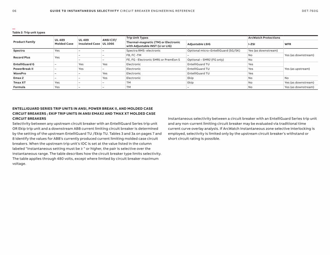
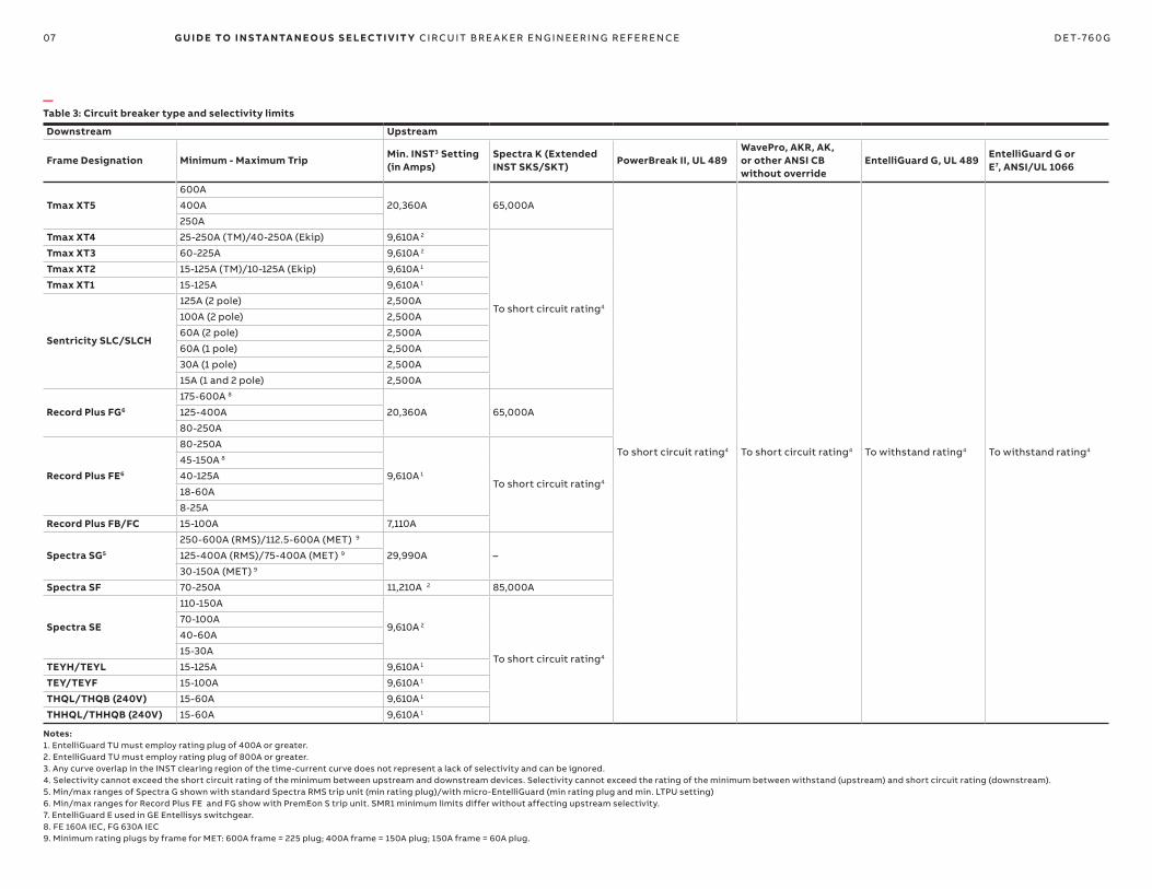
ENTELLIGUARD SERIES TRIP UNITS IN ANSI, POWER BREAK II, AND MOLDED CASE CIRCUIT BREAKERS ; EKIP TRIP UNITS IN ANSI EMAX2 AND TMAX XT MOLDED CASE CIRCUIT BREAKERSSelectivity between any upstream circuit breaker with an EntelliGuard Series trip unit OR Ekip trip unit and a downstream ABB current limiting circuit breaker is determined by the setting of the upstream EntelliGuard TU /Ekip TU. Tables 3 and 3a on pages 7 and 8 identify the values for ABB’s currently produced current limiting molded case circuit breakers. When the upstream trip unit’s IOC is set at the value listed in the column labeled “Instantaneous setting must be ≥ “ or higher, the pair is selective over the instantaneous range. The table describes how the circuit breaker type limits selectivity. The table applies through 480 volts, except where limited by circuit breaker maximum voltage.
Product FamilyUL 489 Molded Case
UL 489 Insulated Case
ANSI C37/UL 1066
Trip Unit Types ArcWatch ProtectionsThermal-magnetic (TM) or Electronic with Adjustable INST (LI or LIG)
Adjustable LSIG I-ZSI WFR
Spectra Yes – – Spectra RMS- electronic Optional micro–EntelliGuard (SG/SK) Yes (as downstream)
Yes (as downstream)Record Plus Yes
– – FB, FC -TM – No
– – FE, FG - Electronic SMR1 or PremEon S Optional – SMR2 (FG only) No
EntelliGuard G – Yes Yes Electronic EntelliGuard TU Yes
Yes (as upstream)PowerBreak II – Yes – Electronic EntelliGuard TU Yes
WavePro – – Yes Electronic EntelliGuard TU Yes
Emax 2 – – Yes Electronic Ekip No No
Tmax XT Yes – – TM Ekip No Yes (as downstream)
Formula Yes – – TM – No Yes (as downstream)
—Table 2: Trip unit types
Instantaneous selectivity between a circuit breaker with an EntelliGuard Series trip unit and any non-current limiting circuit breaker may be evaluated via traditional time current curve overlay analysis. If ArcWatch Instantaneous zone selective interlocking is employed, selectivity is limited only by the upstream circuit breaker’s withstand or short circuit rating is possible.
07 G U I D E TO I N S TA NTA N EO U S S E LEC TI V IT Y CI R CU IT B R E A K ER EN G I N EER I N G R EFER EN CE D E T-76 0 G
Notes:1. EntelliGuard TU must employ rating plug of 400A or greater.2. EntelliGuard TU must employ rating plug of 800A or greater.3. Any curve overlap in the INST clearing region of the time-current curve does not represent a lack of selectivity and can be ignored.4. Selectivity cannot exceed the short circuit rating of the minimum between upstream and downstream devices. Selectivity cannot exceed the rating of the minimum between withstand (upstream) and short circuit rating (downstream).5. Min/max ranges of Spectra G shown with standard Spectra RMS trip unit (min rating plug)/with micro-EntelliGuard (min rating plug and min. LTPU setting)6. Min/max ranges for Record Plus FE and FG show with PremEon S trip unit. SMR1 minimum limits differ without affecting upstream selectivity.7. EntelliGuard E used in GE Entellisys switchgear.8. FE 160A IEC, FG 630A IEC9. Minimum rating plugs by frame for MET: 600A frame = 225 plug; 400A frame = 150A plug; 150A frame = 60A plug.
Downstream Upstream
Frame Designation Minimum - Maximum TripMin. INST3 Setting (in Amps)
Spectra K (Extended INST SKS/SKT)
PowerBreak II, UL 489WavePro, AKR, AK, or other ANSI CB without override
EntelliGuard G, UL 489EntelliGuard G or E7, ANSI/UL 1066
Tmax XT5600A
20,360A 65,000A
To short circuit rating4 To short circuit rating4 To withstand rating4 To withstand rating4
400A
250A
Tmax XT4 25-250A (TM)/40-250A (Ekip) 9,610A 2
To short circuit rating4
Tmax XT3 60-225A 9,610A 2
Tmax XT2 15-125A (TM)/10-125A (Ekip) 9,610A 1
Tmax XT1 15-125A 9,610A 1
Sentricity SLC/SLCH
125A (2 pole) 2,500A
100A (2 pole) 2,500A
60A (2 pole) 2,500A
60A (1 pole) 2,500A
30A (1 pole) 2,500A
15A (1 and 2 pole) 2,500A
Record Plus FG6
175-600A 8
20,360A 65,000A125-400A
80-250A
Record Plus FE6
80-250A
9,610A 1
To short circuit rating4
45-150A 8
40-125A
18-60A
8-25A
Record Plus FB/FC 15-100A 7,110A
Spectra SG5
250-600A (RMS)/112.5-600A (MET) 9
29,990A –125-400A (RMS)/75-400A (MET) 9
30-150A (MET) 9
Spectra SF 70-250A 11,210A 2 85,000A
Spectra SE
110-150A
9,610A 2
To short circuit rating4
70-100A
40-60A
15-30A
TEYH/TEYL 15-125A 9,610A 1
TEY/TEYF 15-100A 9,610A 1
THQL/THQB (240V) 15-60A 9,610A 1
THHQL/THHQB (240V) 15-60A 9,610A 1
—Table 3: Circuit breaker type and selectivity limits

08 G U I D E TO I N S TA NTA N EO U S S E LEC TI V IT Y CI R CU IT B R E A K ER EN G I N EER I N G R EFER EN CE D E T-76 0 G
Downstream Upstream
Frame Designation Minimum-Maximum TripMin. INST Setting (in Amps)
Tmax XT7Emax 2 1.2, ANSI/UL 1066
Emax 2 2.2, ANSI/UL 1066
Emax 2 4.2, ANSI/UL 1066
Emax 2 6.2, ANSI/UL 1066
Tmax XT6800
18000A –
To withstand rating2 To withstand rating2 To withstand rating2 To withstand rating2
600
Tmax XT5600
15000A400
250
Tmax XT4 25-250A(TM)/40-250A (Ekip) 6,000A 100,000
Tmax XT3 60-225A 6,000A To short circuit rating2
Tmax XT2 15-125A (TM)/10-125A (Ekip) 4,000A 100,000
Tmax XT1 15-125A 4,000A
To short circuit rating2Formula A2 (240V) 125-250A 6,000A
Sentricity SLC (240V) 15-125A 2,500A
Sentricity SLCH (240V) 15-125A 2,500A
Record Plus FG4
175-600A 5
15,000A125-400A
80-250A
Record Plus FE4
80-250A
6,000A To short circuit rating2
45-150A 5
40-125A
18-60A
8-25A
Record Plus FB/FC 15-100A 6,000A 65,000
Spectra SG3
250-600A (RMS)/112.5-600A (MET) 6
18000A –125-400A (RMS)/75-400A (MET) 6
30-150A (MET) 6
Spectra SF 70-250A 8,000A
To short circuit rating2
Spectra SE
110-150A
4,000A70-100A
40-60A
15-30A
TEYL/TEYH 15-125A 4,000A
TEYF/TEY 15-100A 4,000A
THQL/THQB (240V) 15-125A 4,000A
THHQL/THHQB (240V) 15-125A 4,000A
—Table 3a: Circuit breaker types and selectivity limits
Notes:1. Any curve overlap in the INST clearing region of the time-current curve does not represent a lack of selectivity and can be ignored.2. Selectivity cannot exceed the short circuit rating of the minimum between upstream and downstream devices. Selectivity cannot exceed the rating of the minimum between withstand (upstream) and short circuit rating (downstream).3. Min/max ranges of Spectra G shown with standard Spectra RMS trip unit (min rating plug)/with micro-EntelliGuard (min rating plug and min. LTPU setting)4. Min/max ranges for Record Plus FE and FG show with PremEon S trip unit. SMR1 minimum limits differ without affecting upstream selectivity. 3 Pole only.5. FE 160A IEC, FG 630A IEC 6. Minimum rating plugs by frame for MET: 600A frame = 225 plug; 400A frame = 150A plug; 150A frame = 60A plug.
100,000
100,000

09 G U I D E TO I N S TA NTA N EO U S S E LEC TI V IT Y CI R CU IT B R E A K ER EN G I N EER I N G R EFER EN CE D E T-76 0 G
SELECTIVITY WITH ENTELLIGUARD TU TRIP UNITS IN ANSI, POWER BREAK II, AND MOLDED CASE CIRCUIT BREAKERSThe table below identifies maximum instantaneous pickup multipliers for various types and sizes of ABB circuit breakers. The lower part of the table identifies the maximum instantaneous pickup (in amperes) for various circuit breaker, sensor, and rating plug combinations. If you compare this value with the values in the third column of the preceding table, you can tell if a pair of circuit breakers can be selective.
Downstream device with EntelliGuard TU Trip Unit
Selective Spectra K(SKS and SKT)
Power Break II,UL 489 CB
Legacy WavePro orAKR, ANSI CB
EntelliGuard G,ANSI/UL (Standard INST)
EntelliGuard G,ANSI (Extended INST)
Max Instantaneous1 in X800A frame 25.5 15 15 15 30
1000A frame 20.5 – – – –
1200A frame 17 – – – –
1600A frame – 15 15 15 30
2000A frame – 15 15 15 30
3000A frame – 13 15 30
3200A frame – – 13 15 30
4000A frame – 10 10 15 23
5000A frame – – 7 15 19
6000A frame (UL 489 only) – – – 15 –
Amperes per above multipliers
800A frame, 800A plug 20,400 12,000 12,000 12,000 24,000
1000A frame/sensor2 20,500 – – – –
1200A frame/sensor2 20,400 – – – –
1600A frame, 1600A plug – 24,000 24,000 24,000 48,000
2000A frame, 2000A plug – 30,000 30,000 30,000 60,000
3000A frame, 3000A plug – 39,000 – 45,000 90,000
3200A frame, 3200A plug – – 41,600 48,000 96,000
4000A frame, 4000A plug – 40,000 40,000 60,000 92,000
5000A frame, 5000A plug – – 35,000 75,000 95,000
6000A frame, 6000A plug – – – 90,000 –
—Table 4: Maximum instantaneous pickup for EntelliGuard family trip units in various circuit breakers types
Notes:1. Frame determines maximum instantaneous pickup (X) for PowerBreak II, WavePro, and Selective Spectra K. Plug/Icw ratio determines maximum possible for EntelliGuard G. EntelliGuard G values shown are maximum withstand tiers.2. Spectra K only.
For Power Break II, WavePro and EntelliGuard G maximum instantaneous is a multiple of rating plug; the above values for those breakers may be lower if a smaller rating plug than maximum for frame is used. For Selective Spectra K, maximum instantaneous is a multiple of frame. In Power Break II, WavePro, and Selective Spectra K the maximum instantaneous multiplier is limited by frame rating. In EntelliGuard G, the maximum instantaneous X may be limited by withstand). The amperes listed above, multiplied by 0.9, provide maximum selectivity above non-current limiting circuit breakers if instantaneous is adjusted to maximum and no zone selective interlocking is used.

10 G U I D E TO I N S TA NTA N EO U S S E LEC TI V IT Y CI R CU IT B R E A K ER EN G I N EER I N G R EFER EN CE D E T-76 0 G
SELECTIVITY WITH RECORD PLUS FE AND FGThe table below identifies maximum selectivity between Record Plus upstream circuit breakers and typical downstream branch devices. The table assumes the INST pickup setting of the upstream device adjusted to its maximum. Downstream devices (where adjustable) may be adjusted to lower INST pickup settings without affecting the maximum selectivity of the pair. The table applies through 480 volts, as limited by circuit breaker maximum voltage.
DownstreamUpstreamRecord Plus FG Record Plus FE
Amperes Poles 600 400 250 250 150 & 125Record Plus FE Electronic 20-250 2 and 3 100,000 – – – –
Record Plus FB/FC 15-100 1, 2 and 3 65,000 65,000 65,000 – –
TEYL
80-125 2 and 3 65,000 65,000 65,000 – –
35-70 1, 2 and 3 65,000 65,000 65,000 – –
15-30 2 and 3 65,000 65,000 65,000 – –
15-30 1 65,000 65,000 65,000 14,000 10,000
TEYH
80-125 2 and 3 35,000 35,000 35,000 – –
35-70 1, 2 and 3 35,000 35,000 35,000 – –
15-30 2 and 3 35,000 35,000 35,000 – –
15-30 1 35,000 35,000 35,000 14,000 10,000
TEYF35-100 1, 2 and 3 14,000 14,000 14,000 – –
15-30 2 and 3 14,000 14,000 14,000 – –
15-30 1P 14,000 14,000 14,000 14,000 10,000
TEY
70-100 1, 2 and 3 6,000 4,000 2,500 – –
35-60 2 and 3 10,000 10,000 2,500 – –
15-30 2 and 3 14,000 14,000 14,000 – –
35-60 1 10,000 10,000 2,500 – –
15-30 1 14,000 14,000 14,000 10,000 10,000
THQC/THQL/THQB
125 2 10,000 10,000 2,500 – –
70-100 1, 2 and 3 10,000 10,000 2,500 – –
35-60 2 and 3 10,000 10,000 10,000 4,000 4,000
15-30 2 and 3 10,000 10,000 10,000 6,000 6,000
35-60 1 10,000 10,000 10,000 – –
15-30 1 10,000 10,000 10,000 10,000 10,000
THHQC/THHQL/THHQB
125 2 22,000 22,000 2,500 – –
70-100 1, 2 and 3 22,000 22,000 2,500 – –
35-60 2 and 3 22,000 22,000 10,000 4,000 4,000
15-30 2 and 3 22,000 22,000 22,000 6,000 6,000
35-60 1 22,000 22,000 10,000 – –
15-30 1 22,000 22,000 22,000 14,000 14,000
—Table 5: Selectivity for typical 600A and smaller combinations

11 G U I D E TO I N S TA NTA N EO U S S E LEC TI V IT Y CI R CU IT B R E A K ER EN G I N EER I N G R EFER EN CE D E T-76 0 G
SELECTIVITY WITH TMAX XTThe table below identifies the maximum selectivity between Tmax XT upstream circuit breakers and Tmax XT downstream branch devices. The table assumes the INST pickup setting of the upstream device is adjusted to its maximum. Downstream devices (where adjustable) may be adjusted to lower INST pickup settings without affecting the maximum selectivity of the pair. The table applies through 480 volts, as limited by circuit breaker maximum voltage.
Downstream Upstream
Amperes PolesTmax XT6 (Ekip) Tmax XT5 (Ekip) Tmax XT4 (Ekip) Tmax XT2 (Ekip)800 600 600 400 250 250 125
Tmax XT4 250 2, 3, and 4 65,000 65,000 100,0001 100,0001 – – –
Tmax XT3 225 2, 3, and 4 – – 35,0001 – – – –
Tmax XT2 125 2, 3, and 4 65,000 65,000 100,0001 100,0001 100,0001 – –
Tmax XT1 125 2, 3, and 4 – – 65,0001 65,0001 65,0001 – –
Formula A2 (240V)250 2 and 3 25,000 25,000 25,000 25,000 – – –
125 2 and 3 25,000 25,000 25,000 25,000 – – –
Sentricity SLC (240V)
125 2 10,000 10,000 10,000 10,000 10,000 10,000 –
100 2 10,000 10,000 10,000 10,000 10,000 10,000 –
60 1 and 2 10,000 10,000 10,000 10,000 10,000 10,000 10,000
30 1 and 2 10,000 10,000 10,000 10,000 10,000 10,000 10,000
15 1 and 2 10,000 10,000 10,000 10,000 10,000 10,000 10,000
Sentricity SLCH (240V)
125 2 22,000 22,000 22,000 22,000 22,000 22,000 –
100 2 22,000 22,000 22,000 22,000 22,000 22,000 –
60 1 and 2 22,000 22,000 22,000 22,000 22,000 22,000 22,000
30 1 and 2 22,000 22,000 22,000 22,000 22,000 22,000 22,000
15 1 and 2 22,000 22,000 22,000 22,000 22,000 22,000 22,000
—Table 5a: Selectivity for typical 800A and smaller combinations
Notes:1. Shown selectivity is valid with Ekip DIP version of the trip unit only. Please contact ABB for reduced selectivity ratings with Ekip Touch/High Touch trip unit.
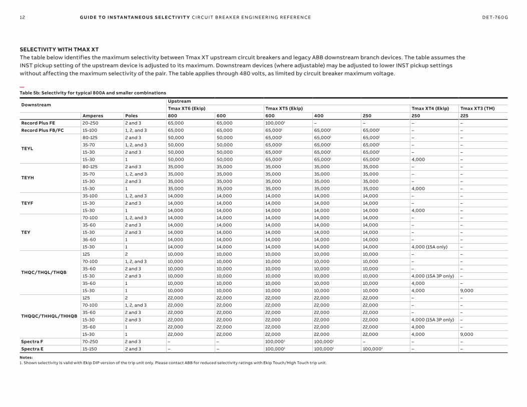
12 G U I D E TO I N S TA NTA N EO U S S E LEC TI V IT Y CI R CU IT B R E A K ER EN G I N EER I N G R EFER EN CE D E T-76 0 G
SELECTIVITY WITH TMAX XTThe table below identifies the maximum selectivity between Tmax XT upstream circuit breakers and legacy ABB downstream branch devices. The table assumes the INST pickup setting of the upstream device is adjusted to its maximum. Downstream devices (where adjustable) may be adjusted to lower INST pickup settings without affecting the maximum selectivity of the pair. The table applies through 480 volts, as limited by circuit breaker maximum voltage.
DownstreamUpstreamTmax XT6 (Ekip) Tmax XT5 (Ekip) Tmax XT4 (Ekip) Tmax XT3 (TM)
Amperes Poles 800 600 600 400 250 250 225Record Plus FE 20-250 2 and 3 65,000 65,000 100,0001 – – – –
Record Plus FB/FC 15-100 1, 2, and 3 65,000 65,000 65,0001 65,0001 65,0001 – –
TEYL
80-125 2 and 3 50,000 50,000 65,0001 65,0001 65,0001 – –
35-70 1, 2, and 3 50,000 50,000 65,0001 65,0001 65,0001 – –
15-30 2 and 3 50,000 50,000 65,0001 65,0001 65,0001 – –
15-30 1 50,000 50,000 65,0001 65,0001 65,0001 4,000 –
TEYH
80-125 2 and 3 35,000 35,000 35,000 35,000 35,000 – –
35-70 1, 2, and 3 35,000 35,000 35,000 35,000 35,000 – –
15-30 2 and 3 35,000 35,000 35,000 35,000 35,000 – –
15-30 1 35,000 35,000 35,000 35,000 35,000 4,000 –
TEYF35-100 1, 2, and 3 14,000 14,000 14,000 14,000 14,000 – –
15-30 2 and 3 14,000 14,000 14,000 14,000 14,000 – –
15-30 1 14,000 14,000 14,000 14,000 14,000 4,000 –
TEY
70-100 1, 2, and 3 14,000 14,000 14,000 14,000 14,000 – –
35-60 2 and 3 14,000 14,000 14,000 14,000 14,000 – –
15-30 2 and 3 14,000 14,000 14,000 14,000 14,000 – –
36-60 1 14,000 14,000 14,000 14,000 14,000 – –
15-30 1 14,000 14,000 14,000 14,000 14,000 4,000 (15A only) –
THQC/THQL/THQB
125 2 10,000 10,000 10,000 10,000 10,000 – –
70-100 1, 2, and 3 10,000 10,000 10,000 10,000 10,000 – –
35-60 2 and 3 10,000 10,000 10,000 10,000 10,000 – –
15-30 2 and 3 10,000 10,000 10,000 10,000 10,000 4,000 (15A 3P only) –
35-60 1 10,000 10,000 10,000 10,000 10,000 4,000 –
15-30 1 10,000 10,000 10,000 10,000 10,000 4,000 9,000
THQQC/THHQL/THHQB
125 2 22,000 22,000 22,000 22,000 22,000 – –
70-100 1, 2, and 3 22,000 22,000 22,000 22,000 22,000 – –
35-60 2 and 3 22,000 22,000 22,000 22,000 22,000 – –
15-30 2 and 3 22,000 22,000 22,000 22,000 22,000 4,000 (15A 3P only) –
35-60 1 22,000 22,000 22,000 22,000 22,000 4,000 –
15-30 1 22,000 22,000 22,000 22,000 22,000 4,000 9,000
Spectra F 70-250 2 and 3 – – 100,0001 100,0001 – – –
Spectra E 15-150 2 and 3 – – 100,0001 100,0001 100,0001 – –
—Table 5b: Selectivity for typical 800A and smaller combinations
Notes:1. Shown selectivity is valid with Ekip DIP version of the trip unit only. Please contact ABB for reduced selectivity ratings with Ekip Touch/High Touch trip unit.

13 G U I D E TO I N S TA NTA N EO U S S E LEC TI V IT Y CI R CU IT B R E A K ER EN G I N EER I N G R EFER EN CE D E T-76 0 G
—Figure 4: Selectivity using ArcWatch I-ZSI and WFR tested breaker pairs with switchboard service entrance
UTIL-2100000 MVA150 (X/R)100000 MVA150 (X/R)
13.2 kV
BUS-8
TX-12500 / 3333.25 kVA13.2 - 0.48 kV5.75%
4000AF EntelliGuard GEntelliGuard TU (ETU) TU LSI, I-ZSIUL 1066 or UL 489 version
Instantaneously selectivevia I-ZSI as indicated onTable 10.
Pair is instantaneouslyselective to 65 kAICvia the waveform recognitionalgorithm, refer to Table 3.
Pair is instantaneously selective to 65 kAIC per tested combination, refer toTable 5.
Spectra Switchboard, 480V, 65 kAIC
Molded Case BreakerRecord Plus FE250AF/250AS/250AT
Molded Case BreakerRecord Plus FG600AF/ 600AS/ 600AT
Molded Case BreakerRecord Plus FG600AF/600AS/600AT
Molded Case BreakerRecord Plus FG600AF/600AS/600AT
Molded case breakerSpectra K frame 1200AFmicroEntelliGuard tripLSI, I-ZSI
Spectra Switchboard, MLO, 480V, 65 kAIC
Spectra Panelboard - 65 kAICMLO or FG600A main, 480V
Molded Case BreakerRecord Plus FEFE 250AS/250AT
Molded Case BreakerRecord PlusFE 250AS/250AT
A Series Panelboard 14 kAIC max
Spectra Panelboard480V, main breaker65 kAIC max
Molded Case BreakerTEYF 15-30A 1 Pole
Molded Case BreakerRecord PlusFB 100AF/70AT
Molded Case BreakerRecord PlusFG 600AF/250AS/100AT
Molded Case BreakerTHQB35A max 1, 2, and 3 pole
A Series Panelboard, 208V
Tranformer protectionand LSI coordinationper the predefinedtemplate for a 30 kVAtransformer from DET-654.
Pair is instantaneouslyselective to 65 kAICper documentedcombination. Refer toTable 5.
Pair is instantaneouslyselective to 14 kAIC per documentedcombination. Refer to Table 5.
TX-230 kVA0.48 - 0.208 kV4%
Pair is instantaneouslyselective to 65 kAICvia the waveform recognitionalgorithm, refer to Table 3.
Duplicate breakers inseries do not needto coordinate.
This examples illustrates a switchboard service entrance product equipped with an ANSI main breaker and molded case feeders. Instantaneous selectivity is achieved within the switchboard via two methods:a) Instantaneous Zone Selective Interlocking - (I-ZSI) between the main and 1200AF feederb) The waveform recognition algorithm in the EntelliGuard trip unit above a current limiting feeder.
Instantaneous selectivity between the switchboard feeders and the downstream breakers is achieved using:a) The waveform recognition algorithm in the SK EntelliGuard trip unit above a current limiting feeder.b) Documented breaker pairs.c) Tranformer templates in DET-654.
—Figure 4: Selectivity using ArcWatch I-ZSI and WFR tested breaker pairs with switchboard service entrance

14 G U I D E TO I N S TA NTA N EO U S S E LEC TI V IT Y CI R CU IT B R E A K ER EN G I N EER I N G R EFER EN CE D E T-76 0 G
UTIL-2100000 MVA150 (X/R)100000 MVA150 (X/R)
13.2 kV
BUS-8
TX-12500 / 3333.25 kVA13.2 - 0.48 kV5.75%
ANSI Circuit Breaker (UL 1066)4000AF EntelliGuard GEntelliGuard TU (ETU) TU LSI, I-ZSI
Instantaneously selectivityvia I-ZSI as indicated on Table 7.
Pair is instantaneouslyselective to 65 kAICvia the waveform recognitionalgorithm. Refer to Table 3.
Pair is instantaneouslyselective to 65 kAICper documented combination.Refer to Table 5.
AKD-20 LV Switchgear, 480V, 65 kA
ANSI Circuit Breaker1600AF EntelliGuard GEntelliGuard TU Trip with I-ZSI
Molded Case BreakerRecord Plus FG600AF/600AS/600AT
Molded Case BreakerRecord Plus FG600AF/600AS/600AT
Molded Case BreakerRecord Plus FG600AF/600AS/600AT
ANSI Circuit Breaker1600AF EntelliGuard GEntelliGuard TU Trip with I-ZSI
Spectra Switchboard, MLO, 480V, 65 kA
Spectra Panelboard - 65 kAMLO or FG600A main, 480V
Molded Case BreakerRecord PlusFE 250AS/250AT
A Series Panelboard 14 kA max
Spectra Panelboard480V, main breaker65 kA max
Molded Case BreakerTEYF 15-30A 1 Pole
Molded Case BreakerRecord PlusFB 100AF/70AT
Molded Case BreakerRecord Plus FG600AF/250AS/100AT
Molded Case BreakerTHQB - 35A max 1, 2, & 3 pole
A Series Panelboard, 208V
Tranformer protectionand LSI coordinationper the predefinedtemplate for a 30 kVAtransformer from DET-654.
Pair is instantaneouslyselective to 65 kAIC per documentedcombination. Refer toTable 5.
Pair is instantaneouslyselective to 65 kAIC per documentedcombination. Refer toTable 5.
TX-230 kVA0.48 - 0.208 kV4%
Instantaneously selectivevia I-ZSI as indicated on Table 7.
Duplicate breakers inseries do not needto coordinate.
This example illustrates a switchgear service entrance product equipped with an ANSImain and feeder breakers. Instantaneous selectivity is achieved within the switchgear viaInstantaneous Zone Selective Interlocking (I-ZSI), between the main and 1600AF feeders.
Instantaneous selectivity between the switchgear feeders and the downstream moldedcase breakers is achieved using:a) The waveform recognition algorithm in the EntelliGuard TU trip unit above a current limiting feeder (e.g., Record Plus FG).b) Documented breaker pairs (e.g., Record Plus FG to FE or FB).c) Transformer templates defined in DET-654.
The example highlights both 480V and 208V paths.
—Figure 5: Selectivity using ArcWatch I-ZSI and WFR tested breaker pairs with switchgear service entrance, 480V and 208V paths—Figure 5: Selectivity using ArcWatch I-ZSI and WFR tested breaker pairs with switchgear service entrance, 480V and 208V paths

15 G U I D E TO I N S TA NTA N EO U S S E LEC TI V IT Y CI R CU IT B R E A K ER EN G I N EER I N G R EFER EN CE D E T-76 0 G
ARCWATCH I-ZSI ON ENTELLIGUARD TU TRIP UNITS IN ANSI WAVEPRO CIRCUIT BREAKERSMaximum instantaneous selectivity that may be achieved using Instantaneous Zone Selective Interlocking between these WavePro Low Voltage Power circuit breakers. Limited by short circuit rating of downstream device or upstream device.
DownstreamUpstreamWavePro ANSI Low Voltage Power CB. Long Time Curves, Short Time pickup, and instantaneous pickup must be adjusted per TCC
WavePro WPS-08 WPH-08 WPX-08 WPS-16 WPH-16 WPX-16 WPS-20 WPS-32 WPH-32 WPX-32 WPS-40 WPX-40 WPS-50 WPX-50WPS-08 30 30 30 30 30 30 30 30 30 30 30 30 30 30
WPH-08 30 42 42 30 42 42 42 42 42 42 42 42 42 42
WPX-08 30 42 65 30 42 65 65 65 65 65 65 65 65 65
WPS-16 – – – 30 30 30 30 30 30 30 30 30 30 30
WPH-16 – – – 30 42 42 42 42 42 42 42 42 42 42
WPX-16 – – – 30 42 65 65 65 65 65 65 65 65 65
WPS-20 – – – – – – 65 65 65 65 65 65 65 65
WPS-32 – – – – – – – 65 65 65 65 65 65 65
WPH-32 – – – – – – – 65 85 85 85 85 85 85
WPX-32 – – – – – – – 65 85 100 85 100 85 100
WPS-40 – – – – – – – – – – 85 85 85 85
WPX-40 – – – – – – – – – – 85 100 85 100
WPS-50 – – – – – – – – – – – – 85 85
WPX-50 – – – – – – – – – – – – 85 100
—Table 6: Selectivity with EntelliGuard TU in ANSI WavePro circuit breakers using I-ZSI
Notes:Selectivity values are shown in kA.
16 G U I D E TO I N S TA NTA N EO U S S E LEC TI V IT Y CI R CU IT B R E A K ER EN G I N EER I N G R EFER EN CE D E T-76 0 G
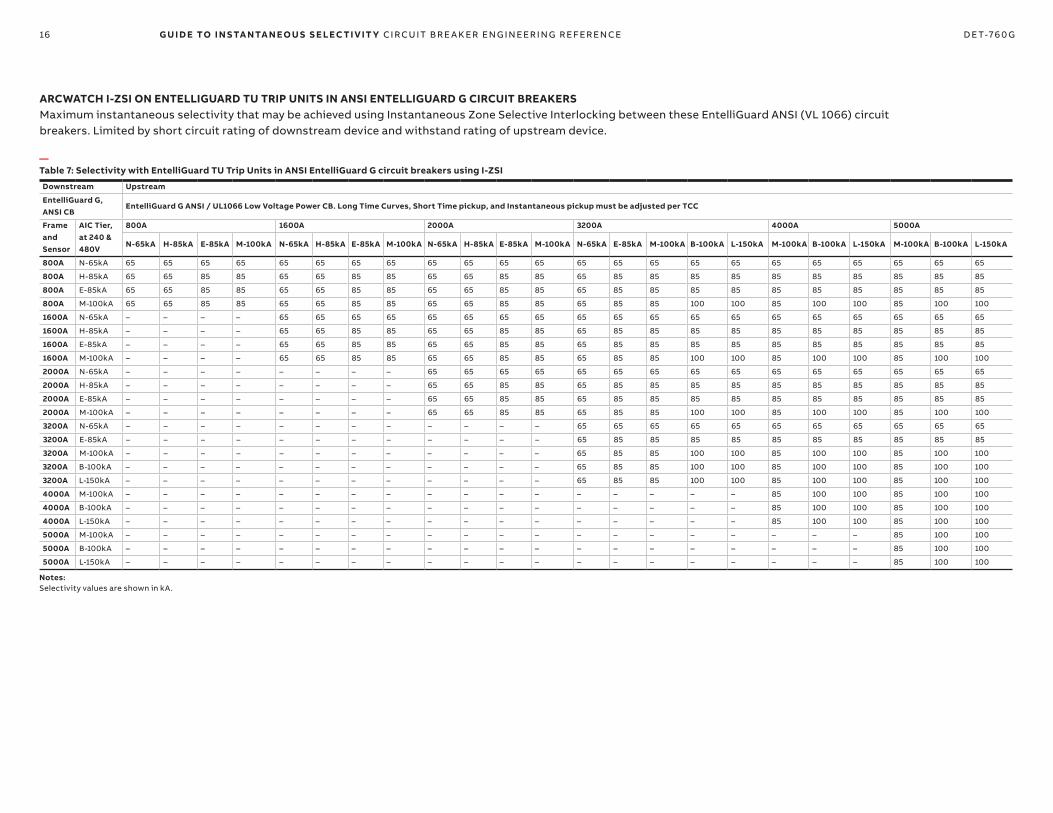
ARCWATCH I-ZSI ON ENTELLIGUARD TU TRIP UNITS IN ANSI ENTELLIGUARD G CIRCUIT BREAKERSMaximum instantaneous selectivity that may be achieved using Instantaneous Zone Selective Interlocking between these EntelliGuard ANSI (VL 1066) circuit breakers. Limited by short circuit rating of downstream device and withstand rating of upstream device.
Downstream Upstream
EntelliGuard G, ANSI CB
EntelliGuard G ANSI / UL1066 Low Voltage Power CB. Long Time Curves, Short Time pickup, and Instantaneous pickup must be adjusted per TCC
Frame and Sensor
AIC Tier, at 240 & 480V
800A 1600A 2000A 3200A 4000A 5000A
N-65kA H-85kA E-85kA M-100kA N-65kA H-85kA E-85kA M-100kA N-65kA H-85kA E-85kA M-100kA N-65kA E-85kA M-100kA B-100kA L-150kA M-100kA B-100kA L-150kA M-100kA B-100kA L-150kA
800A N-65kA 65 65 65 65 65 65 65 65 65 65 65 65 65 65 65 65 65 65 65 65 65 65 65
800A H-85kA 65 65 85 85 65 65 85 85 65 65 85 85 65 85 85 85 85 85 85 85 85 85 85
800A E-85kA 65 65 85 85 65 65 85 85 65 65 85 85 65 85 85 85 85 85 85 85 85 85 85
800A M-100kA 65 65 85 85 65 65 85 85 65 65 85 85 65 85 85 100 100 85 100 100 85 100 100
1600A N-65kA – – – – 65 65 65 65 65 65 65 65 65 65 65 65 65 65 65 65 65 65 65
1600A H-85kA – – – – 65 65 85 85 65 65 85 85 65 85 85 85 85 85 85 85 85 85 85
1600A E-85kA – – – – 65 65 85 85 65 65 85 85 65 85 85 85 85 85 85 85 85 85 85
1600A M-100kA – – – – 65 65 85 85 65 65 85 85 65 85 85 100 100 85 100 100 85 100 100
2000A N-65kA – – – – – – – – 65 65 65 65 65 65 65 65 65 65 65 65 65 65 65
2000A H-85kA – – – – – – – – 65 65 85 85 65 85 85 85 85 85 85 85 85 85 85
2000A E-85kA – – – – – – – – 65 65 85 85 65 85 85 85 85 85 85 85 85 85 85
2000A M-100kA – – – – – – – – 65 65 85 85 65 85 85 100 100 85 100 100 85 100 100
3200A N-65kA – – – – – – – – – – – – 65 65 65 65 65 65 65 65 65 65 65
3200A E-85kA – – – – – – – – – – – – 65 85 85 85 85 85 85 85 85 85 85
3200A M-100kA – – – – – – – – – – – – 65 85 85 100 100 85 100 100 85 100 100
3200A B-100kA – – – – – – – – – – – – 65 85 85 100 100 85 100 100 85 100 100
3200A L-150kA – – – – – – – – – – – – 65 85 85 100 100 85 100 100 85 100 100
4000A M-100kA – – – – – – – – – – – – – – – – – 85 100 100 85 100 100
4000A B-100kA – – – – – – – – – – – – – – – – – 85 100 100 85 100 100
4000A L-150kA – – – – – – – – – – – – – – – – – 85 100 100 85 100 100
5000A M-100kA – – – – – – – – – – – – – – – – – – – – 85 100 100
5000A B-100kA – – – – – – – – – – – – – – – – – – – – 85 100 100
5000A L-150kA – – – – – – – – – – – – – – – – – – – – 85 100 100
—Table 7: Selectivity with EntelliGuard TU Trip Units in ANSI EntelliGuard G circuit breakers using I-ZSI
Notes:Selectivity values are shown in kA.
17 G U I D E TO I N S TA NTA N EO U S S E LEC TI V IT Y CI R CU IT B R E A K ER EN G I N EER I N G R EFER EN CE D E T-76 0 G
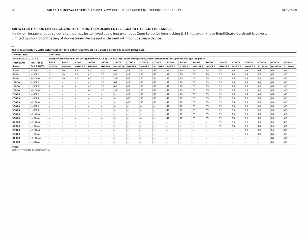
ARCWATCH I-ZSI ON ENTELLIGUARD TU TRIP UNITS IN UL489 ENTELLIGUARD G CIRCUIT BREAKERSMaximum instantaneous selectivity that may be achieved using Instantaneous Zone Selective Interlocking (I-ZSI) between these EntelliGuard UL circuit breakers. Limited by short circuit rating of downstream device and withstand rating of upstream device.
Downstream Upstream
EntelliGuard G, UL, CB EntelliGuard G UL489 Low Voltage Power CB. Long Time Curves, Short Time pickup, and Instantaneous pickup must be adjusted per TCC
Frame and Sensor
AIC Tier, at 240 & 480V
800A 800A 800A 1600A 1600A 1600A 2000A 2000A 2000A 3000A 3000A 3000A 3000A 4000A 4000A 5000A 5000A 6000A 6000A
N-65kA H-85kA M-100kA N-65kA H-85kA M-100kA N-65kA H-85kA M-100kA N-65kA H-85kA M-100kA L-150kA M-100kA L-150kA M-100kA L-150kA M-100kA L-150kA
800A N-65kA 42 50 65 42 50 65 42 50 65 42 50 65 65 65 65 65 65 65 65
800A H-85kA 42 50 65 42 50 85 42 50 65 42 50 65 85 65 85 65 85 65 85
800A M-100kA 42 50 65 42 50 100 42 50 65 42 50 65 85 65 85 65 85 65 85
1600A N-65kA – – – 42 50 65 42 50 65 42 50 65 65 65 65 65 65 65 65
1600A H-85kA – – – 42 50 85 42 50 65 42 50 65 85 65 85 65 85 65 85
1600A M-100kA – – – 42 50 100 42 50 65 42 50 65 85 65 85 65 85 65 85
2000A N-65kA – – – – – – 42 50 65 42 50 65 65 65 65 65 65 65 65
2000A H-85kA – – – – – – 42 50 65 42 50 65 85 65 85 65 85 65 85
2000A M-100kA – – – – – – 42 50 65 42 50 65 85 65 85 65 85 65 85
3000A N-65kA – – – – – – – – – 42 50 65 65 65 65 65 65 65 65
3000A H-85kA – – – – – – – – – 42 50 65 85 65 85 65 85 65 85
3000A M-100kA – – – – – – – – – 42 50 65 85 65 85 65 85 65 85
3000A L-150kA – – – – – – – – – 42 50 65 85 65 85 65 85 65 85
4000A M-100kA – – – – – – – – – – – – – 65 85 65 85 65 85
4000A L-150kA – – – – – – – – – – – – – 65 85 65 85 65 85
5000A M-100kA – – – – – – – – – – – – – – – 65 85 65 85
5000A L-150kA – – – – – – – – – – – – – – – 65 85 65 85
6000A M-100kA – – – – – – – – – – – – – – – – – 65 85
6000A L-150kA – – – – – – – – – – – – – – – – – 65 85
—Table 8: Selectivity with EntelliGuard TU in EntelliGuard G UL 489 Listed circuit breakers using I-ZSI
Notes:Selectivity values are shown in kA.

18 G U I D E TO I N S TA NTA N EO U S S E LEC TI V IT Y CI R CU IT B R E A K ER EN G I N EER I N G R EFER EN CE D E T-76 0 G
ARCWATCH I-ZSI ON SPECTRA MICROENTELLIGUARD MOLDED CASE CIRCUIT BREAKERS (MCCBs)The tables that follow show maximum instantaneous selectivity that may be achieved using Instantaneous Zone Selective Interlocking (I-ZSI) between downstream Spectra molded case circuit breakers provided with Instantaneous Zone Selective Interlocking (I-ZSI) and upstream ABB WavePro Low Voltage Power Circuit Breakers or ABB EntelliGuard G circuit breakers also provided with I-ZSI. Selectivity is limited by the short circuit rating of downstream device or upstream device.
Downstream Devices: Spectra with microEntelliGuard2
Upstream Devices
WPS-08 WPH-08 WPX-08 WPS-16 WPH-16 WPX-16 WPS-20 WPS-32 WPH-32 WPX-32 WPS-40 WPX-40 WPS-50 WPX-50
1200A –1 –1 –1 30 42 65 65 65 85 100 85 100 85 100
800A –1 –1 –1 30 42 65 65 65 85 100 85 100 85 100
600A 30 42 65 30 42 65 65 65 85 100 85 100 85 100
Downstream Devices: Spectra with microEntelliGuard2
Upstream Devices
800A 800A 800A 800A 1600A 1600A 1600A 1600A 2000A 2000A 2000A 2000A 3200A 3200A 3200A 3200A 3200A 4000A 4000A 4000A 5000A 5000A 5000A
N-65kA H-85kA E-85kA M-100kA N-65kA H-85kA E-85kA M-100kA N-65kA H-85kA E-85kA M-100kA N-65kA E-85kA M-100kA B-100kA L-150kA M-100kA B-100kA L-150kA M-100kA B-100kA L-150kA
1200A –1 –1 –1 –1 65 65 85 85 65 65 85 85 65 85 85 100 100 85 100 100 85 100 100
800A –1 –1 –1 –1 65 65 85 85 65 65 85 85 65 85 85 100 100 85 100 100 85 100 100
600A 65 65 85 85 65 65 85 85 65 65 85 85 65 85 85 100 100 85 100 100 85 100 100
—Table 9: Upstream WavePro ANSI circuit breakers
—Table 10: Upstream EntelliGuard G ANSI / UL1066 Circuit Breakers
Notes:1. Spectra circuit breakers may be instantaneously selective if the trip settings allow the Long-Time and Short-Time curves to be selective per examination of the applicable time current curves.2. Spectra G & K circuit breakers are available in multiple short circuit ratings ranging from 35 to 100kA at 480V. Instantaneous selectivity is only possible up to short circuit rating of the lowest device in the selective pair.3. Selectivity values are shown in kA.
19 G U I D E TO I N S TA NTA N EO U S S E LEC TI V IT Y CI R CU IT B R E A K ER EN G I N EER I N G R EFER EN CE D E T-76 0 G
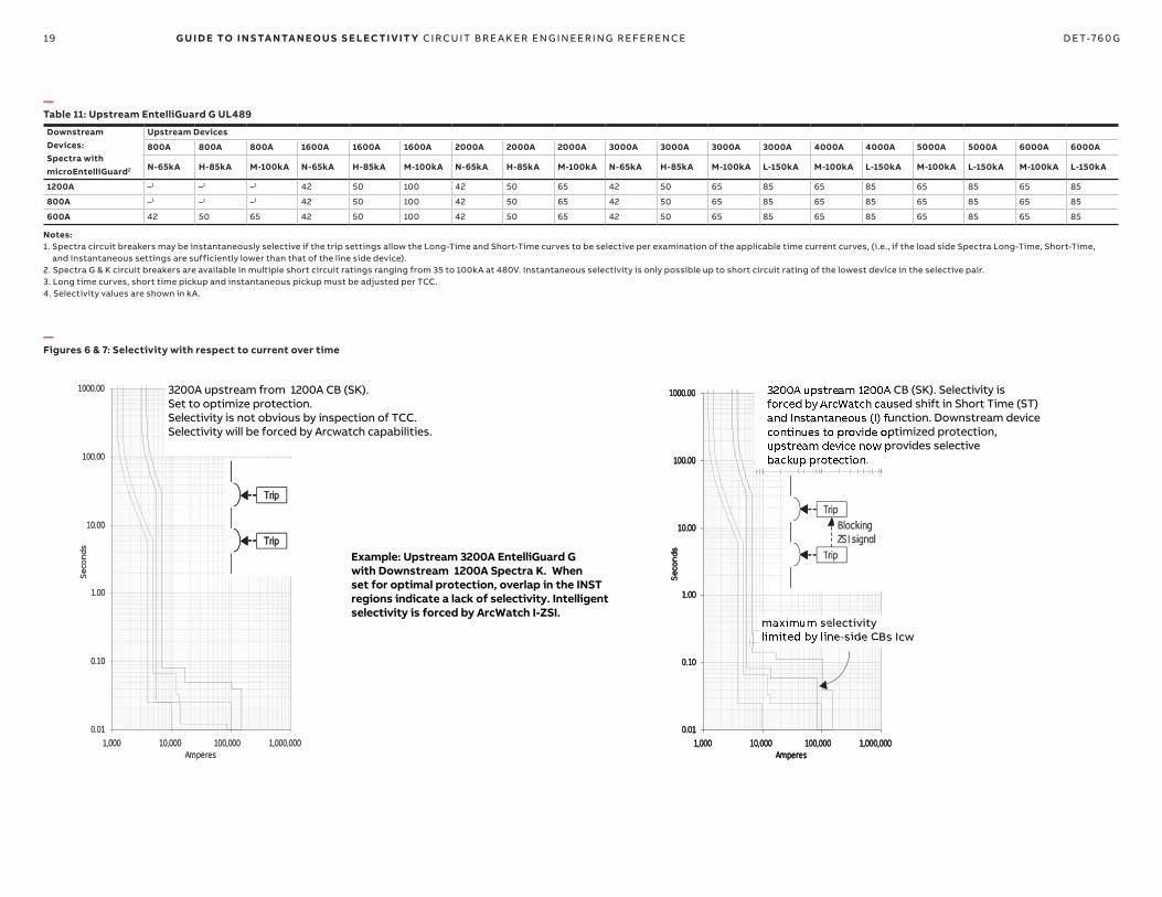
—Figures 6 & 7: Selectivity with respect to current over time
3200A upstream from 1200A CB (SK). Set to optimize protection. Selectivity is not obvious by inspection of TCC. Selectivity will be forced by Arcwatch capabilities.
maximum selectivitylimited by line-side CBs Icw
3200A upstream 1200A CB (SK). Selectivity is forced by ArcWatch caused shift in Short Time (ST) and Instantaneous (I) function. Downstream device continues to provide optimized protection, upstream device now provides selective backup protection.
Example: Upstream 3200A EntelliGuard G with Downstream 1200A Spectra K. When set for optimal protection, overlap in the INST regions indicate a lack of selectivity. Intelligent selectivity is forced by ArcWatch I-ZSI.
Downstream Devices: Spectra with microEntelliGuard2
Upstream Devices
800A 800A 800A 1600A 1600A 1600A 2000A 2000A 2000A 3000A 3000A 3000A 3000A 4000A 4000A 5000A 5000A 6000A 6000A
N-65kA H-85kA M-100kA N-65kA H-85kA M-100kA N-65kA H-85kA M-100kA N-65kA H-85kA M-100kA L-150kA M-100kA L-150kA M-100kA L-150kA M-100kA L-150kA
1200A –1 –1 –1 42 50 100 42 50 65 42 50 65 85 65 85 65 85 65 85
800A –1 –1 –1 42 50 100 42 50 65 42 50 65 85 65 85 65 85 65 85
600A 42 50 65 42 50 100 42 50 65 42 50 65 85 65 85 65 85 65 85
—Table 11: Upstream EntelliGuard G UL489
Notes:1. Spectra circuit breakers may be instantaneously selective if the trip settings allow the Long-Time and Short-Time curves to be selective per examination of the applicable time current curves, (i.e., if the load side Spectra Long-Time, Short-Time,
and Instantaneous settings are sufficiently lower than that of the line side device).2. Spectra G & K circuit breakers are available in multiple short circuit ratings ranging from 35 to 100kA at 480V. Instantaneous selectivity is only possible up to short circuit rating of the lowest device in the selective pair.3. Long time curves, short time pickup and instantaneous pickup must be adjusted per TCC.4. Selectivity values are shown in kA.
—Figures 6 & 7: Selectivity with respect to current over time

This page left intentionally blank

This page left intentionally blank

—ABB Inc.305 Gregson DriveCary, NC 27511
electrification.us.abb.com
© Copyright 2020 ABB. All rights reservedInformation provided is subject to change without notice. Please verify all details with ABB. All values are design or typicalvalues when measured under laboratory conditions, and ABB makes no warranty or guarantee, express or implied, thatsuch performance will be obtained under end-use conditions.GE is a registered trademark used under license from General Electric company.
1SD
C21
00
66
D0
201,
DE
T76
0G
,MA
R20
20