guidance on handling, storage, inspection and construction · pdf file6.2 method statement...
TRANSCRIPT
HG-05- Oct 2016 Uncontrolled copy if printed Page 1 of 13
Acheson & Glover Precast Limited
Guidance on
Handling, storage, inspection and
construction of prestressed flooring planks and precast
concrete units
HG-05- Oct 2016 Uncontrolled copy if printed Page 2 of 13
Acheson & Glover Precast Limited (A+G)
Handling, storage, inspection and construction of prestressed flooring planks and precast concrete units Contents 1. Introduction .................................................................................................................. 3
2. Key Points .................................................................................................................... 3
3. Description of units ..................................................................................................... 3
4. Transport, Delivery and Storage of Prestressed Planks ........................................... 5
5. Installer qualifications ................................................................................................. 5
5.1 General .................................................................................................................. 5
5.2 CSCS/CPCS ........................................................................................................... 6
6. Lifting of pre-cast concrete units................................................................................ 6
6.1 General .................................................................................................................. 6
6.2 Method statement ................................................................................................. 6
6.3 Inspection .............................................................................................................. 7
6.4 Choke hitched chains ........................................................................................... 7
6.5 Lifting slings ......................................................................................................... 8
6.6 Lifting clamps – Prestressed Hollowcore, Solid or Plate Flooring planks ........ 8
6.7 Cast-in lifting devices ........................................................................................... 8
6.8 Lifting inclined units ............................................................................................. 9
6.9 Lifting precast stairs ........................................................................................... 10
6.10 Other lifting ......................................................................................................... 10
7. Installation .................................................................................................................. 10
7.1 Bearings for Flooring Planks ............................................................................. 10
7.2 Barring of units ................................................................................................... 11
7.3 Trapping or jamming of units ............................................................................. 11
7.4 Lightweight thin joint masonry .......................................................................... 12
7.5 Grouting .............................................................................................................. 12
8. For more information … ............................................................................................ 13
HG-05- Oct 2016 Uncontrolled copy if printed Page 3 of 13
1. Introduction The purpose of these notes is to provide guidance and direction on how to properly handle, store, inspect and construct precast and prestressed concrete units manufactured by A+G. Such units include:
Prestressed hollowcore planks
Prestressed solid planks
Prestressed plate
Precast reinforced concrete elements such as stairs, landings, terracing, beams, etc
2. Key Points a) This document should be carefully read and understood before commencement of
work; b) We recommend you also familiarise yourself with the Precast Flooring Federation
Code of Practice for the Safe Erection of Precast Concrete Flooring and Associated Components, available at: http://precastfloors.info/publications/publicationscop.html;
c) The installation of all Precast Concrete Products is a high risk activity. Therefore we strongly recommend that all installation works be undertaken by suitably trained and experienced operatives, currently holding at least, and not limited to, CSCS Precast Concrete Installer Card (accreditation A) and CPCS Slinger Signaller;
d) If in doubt about any aspect of handling, storage, inspection or construction, contact A+G Technical Department on 028 8556 8441.
3. Description of units
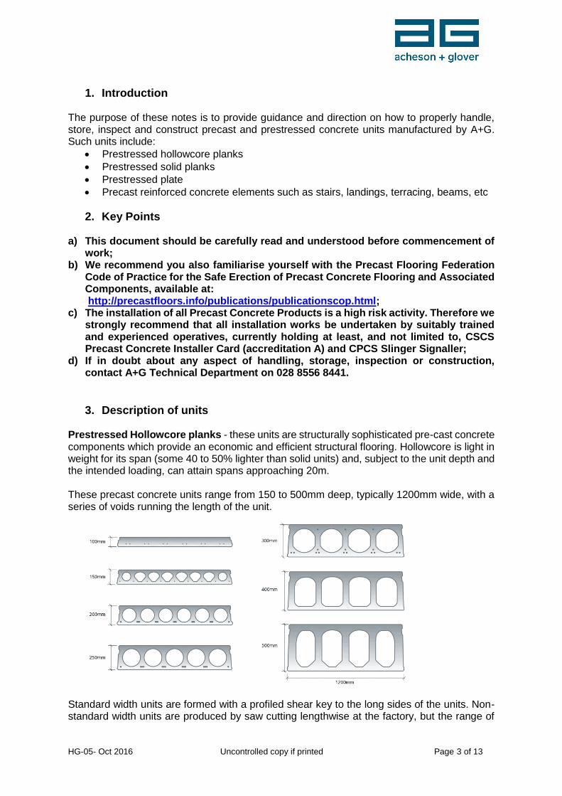
Prestressed Hollowcore planks - these units are structurally sophisticated pre-cast concrete components which provide an economic and efficient structural flooring. Hollowcore is light in weight for its span (some 40 to 50% lighter than solid units) and, subject to the unit depth and the intended loading, can attain spans approaching 20m. These precast concrete units range from 150 to 500mm deep, typically 1200mm wide, with a series of voids running the length of the unit.
Standard width units are formed with a profiled shear key to the long sides of the units. Non-standard width units are produced by saw cutting lengthwise at the factory, but the range of
HG-05- Oct 2016 Uncontrolled copy if printed Page 4 of 13
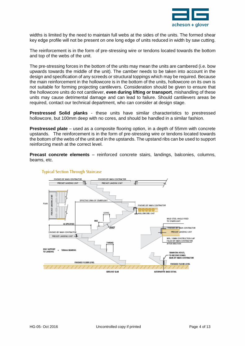
widths is limited by the need to maintain full webs at the sides of the units. The formed shear key edge profile will not be present on one long edge of units reduced in width by saw cutting. The reinforcement is in the form of pre-stressing wire or tendons located towards the bottom and top of the webs of the unit. The pre-stressing forces in the bottom of the units may mean the units are cambered (i.e. bow upwards towards the middle of the unit). The camber needs to be taken into account in the design and specification of any screeds or structural toppings which may be required. Because the main reinforcement in the hollowcore is in the bottom of the units, hollowcore on its own is not suitable for forming projecting cantilevers. Consideration should be given to ensure that the hollowcore units do not cantilever, even during lifting or transport, mishandling of these units may cause detrimental damage and can lead to failure. Should cantilevers areas be required, contact our technical department, who can consider at design stage. Prestressed Solid planks - these units have similar characteristics to prestressed hollowcore, but 100mm deep with no cores, and should be handled in a similar fashion. Prestressed plate – used as a composite flooring option, in a depth of 55mm with concrete upstands. The reinforcement is in the form of pre-stressing wire or tendons located towards the bottom of the webs of the unit and in the upstands. The upstand ribs can be used to support reinforcing mesh at the correct level. Precast concrete elements – reinforced concrete stairs, landings, balconies, columns, beams, etc.
HG-05- Oct 2016 Uncontrolled copy if printed Page 5 of 13
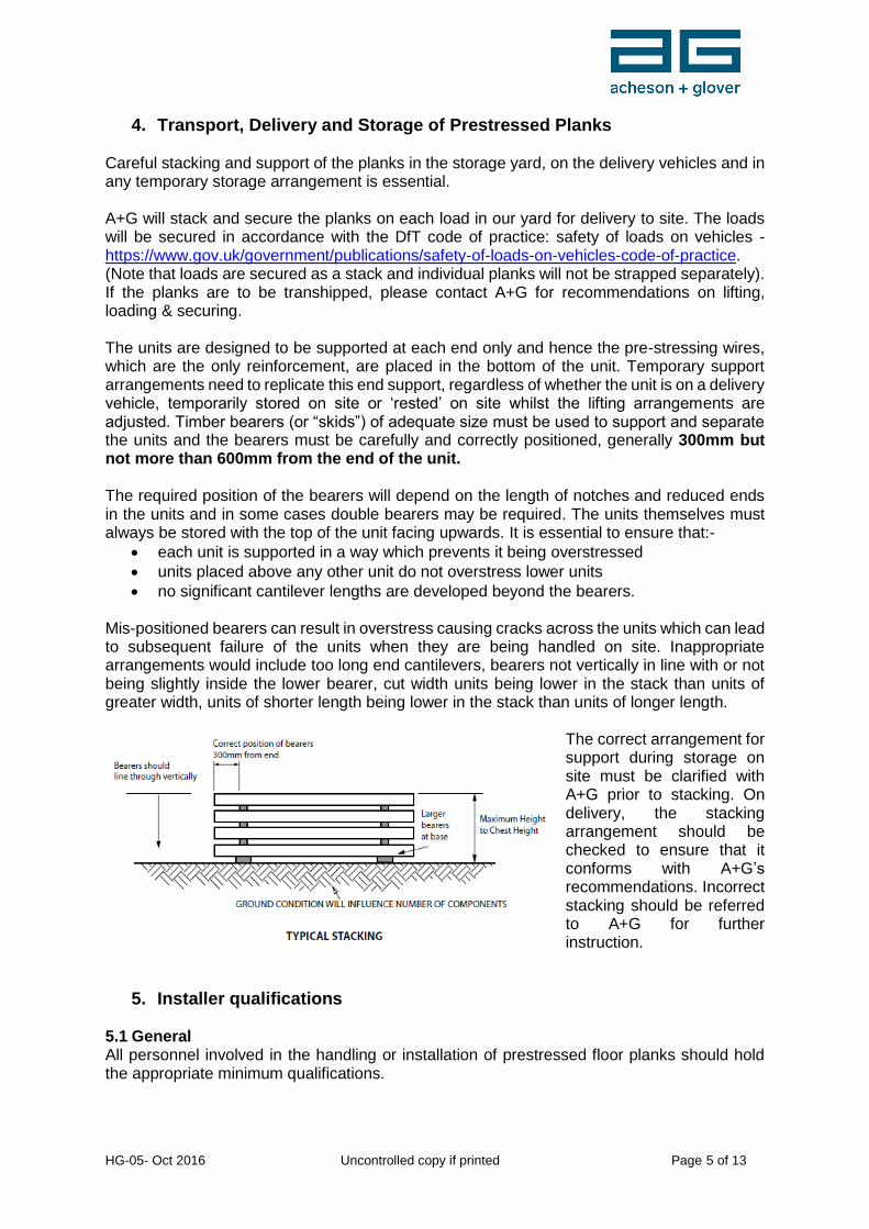
4. Transport, Delivery and Storage of Prestressed Planks Careful stacking and support of the planks in the storage yard, on the delivery vehicles and in any temporary storage arrangement is essential. A+G will stack and secure the planks on each load in our yard for delivery to site. The loads will be secured in accordance with the DfT code of practice: safety of loads on vehicles - https://www.gov.uk/government/publications/safety-of-loads-on-vehicles-code-of-practice. (Note that loads are secured as a stack and individual planks will not be strapped separately). If the planks are to be transhipped, please contact A+G for recommendations on lifting, loading & securing. The units are designed to be supported at each end only and hence the pre-stressing wires, which are the only reinforcement, are placed in the bottom of the unit. Temporary support arrangements need to replicate this end support, regardless of whether the unit is on a delivery vehicle, temporarily stored on site or ‘rested’ on site whilst the lifting arrangements are adjusted. Timber bearers (or “skids”) of adequate size must be used to support and separate the units and the bearers must be carefully and correctly positioned, generally 300mm but not more than 600mm from the end of the unit. The required position of the bearers will depend on the length of notches and reduced ends in the units and in some cases double bearers may be required. The units themselves must always be stored with the top of the unit facing upwards. It is essential to ensure that:-
each unit is supported in a way which prevents it being overstressed
units placed above any other unit do not overstress lower units
no significant cantilever lengths are developed beyond the bearers.
Mis-positioned bearers can result in overstress causing cracks across the units which can lead to subsequent failure of the units when they are being handled on site. Inappropriate arrangements would include too long end cantilevers, bearers not vertically in line with or not being slightly inside the lower bearer, cut width units being lower in the stack than units of greater width, units of shorter length being lower in the stack than units of longer length.
The correct arrangement for support during storage on site must be clarified with A+G prior to stacking. On delivery, the stacking arrangement should be checked to ensure that it conforms with A+G’s recommendations. Incorrect stacking should be referred to A+G for further instruction.
5. Installer qualifications 5.1 General All personnel involved in the handling or installation of prestressed floor planks should hold the appropriate minimum qualifications.
HG-05- Oct 2016 Uncontrolled copy if printed Page 6 of 13
5.2 CSCS/CPCS A+G installation teams will be appropriately trained experienced installers and carry the following minimum qualifications:-
Supervisor / foreman: Crane Supervisor SSSTS/SMSTS
Operatives: Crane supervisor Precast Installer
Slinger/signaller Airbagger
If installation is carried out by others, A+G recommend that they carry at least the same minimum qualifications.
6. Lifting of pre-cast concrete units 6.1 General All lifting equipment and lifting devices (chains, spreader beams, slings, lifting clamps, etc.) must be appropriately rated, have appropriate certification, be in good condition and be used in accordance with all relevant regulations, legislation and good practice. The sequence and timing of installation of units should be carefully considered and planned. As far as practicable the installation sequence should be planned and organised so that lifting paths are unobstructed. Lifting through a partly erected structure is to be avoided wherever reasonably practicable. Where structural or other members obstruct the clear path of the units, additional planning will be required to ensure that a safe installation can be achieved. This may entail the removal of obstructing components and the provision of other temporary measures to ensure stability of the structure is not compromised. A+G Contract Managers can advise. The installation sequence must ensure that stability is maintained at all times – see 7 below. The bearings must be adequate to ensure the safe support of the units at all times – see 7 below. Arrangements should be in place to ensure that lifting over people does not occur. 6.2 Method statement Where units are being erected by A+G, a Method Statement and Site Specific Installation Plan will be provided by an A+G Contract Manager. These documents must address in a clear and understandable manner exactly what lifting methods are to be employed to lift the various lengths, depths and widths of units from the delivery vehicles, exactly how the units are to be installed into the works and exactly what installation sequence is to be followed. Where a range of lengths, widths and depths of units are to be provided, the Installation Plan should make clear exactly what equipment is to be used in each case. In some situations, this may mean that the lifting equipment being used may need to be adjusted (for example, different settings on a lifting beam, a need to shorten lifting chains, a need to use a different size of lifting clamp, etc). Where this does occur:-
the requirements will need to be set out clearly and simply
they will need to be regularly emphasised during the works (frequent toolbox talks, etc)
HG-05- Oct 2016 Uncontrolled copy if printed Page 7 of 13
those carrying out the lifting operations will need the detailed instructions to be readily available to them at all times.
6.3 Inspection Prior to removal of any unit from the delivery vehicle, the unit should be inspected by a ‘Designated Person’ to identify any damage or defects which may be present. Particular attention should be paid to:-
any cast-in lifting devices (see also our procedures for use of cast-in lifters)
stair units
the areas around opened cores
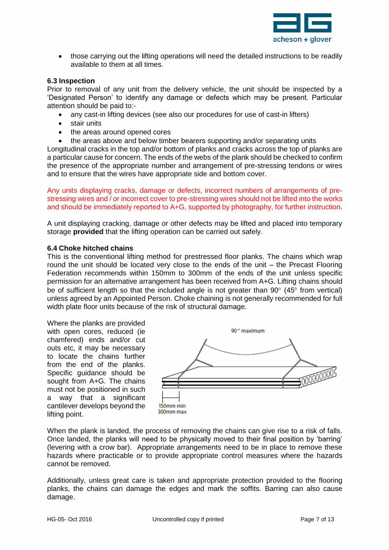
the areas above and below timber bearers supporting and/or separating units Longitudinal cracks in the top and/or bottom of planks and cracks across the top of planks are a particular cause for concern. The ends of the webs of the plank should be checked to confirm the presence of the appropriate number and arrangement of pre-stressing tendons or wires and to ensure that the wires have appropriate side and bottom cover. Any units displaying cracks, damage or defects, incorrect numbers of arrangements of pre-stressing wires and / or incorrect cover to pre-stressing wires should not be lifted into the works and should be immediately reported to A+G, supported by photography, for further instruction. A unit displaying cracking, damage or other defects may be lifted and placed into temporary storage provided that the lifting operation can be carried out safely. 6.4 Choke hitched chains This is the conventional lifting method for prestressed floor planks. The chains which wrap round the unit should be located very close to the ends of the unit – the Precast Flooring Federation recommends within 150mm to 300mm of the ends of the unit unless specific permission for an alternative arrangement has been received from A+G. Lifting chains should
be of sufficient length so that the included angle is not greater than 90 (45 from vertical) unless agreed by an Appointed Person. Choke chaining is not generally recommended for full width plate floor units because of the risk of structural damage. Where the planks are provided with open cores, reduced (ie chamfered) ends and/or cut outs etc, it may be necessary to locate the chains further from the end of the planks. Specific guidance should be sought from A+G. The chains must not be positioned in such a way that a significant cantilever develops beyond the lifting point. When the plank is landed, the process of removing the chains can give rise to a risk of falls. Once landed, the planks will need to be physically moved to their final position by ‘barring’ (levering with a crow bar). Appropriate arrangements need to be in place to remove these hazards where practicable or to provide appropriate control measures where the hazards cannot be removed. Additionally, unless great care is taken and appropriate protection provided to the flooring planks, the chains can damage the edges and mark the soffits. Barring can also cause damage.
HG-05- Oct 2016 Uncontrolled copy if printed Page 8 of 13
6.5 Lifting slings The use of lifting slings is not a method which A+G considers appropriate. If lifting slings are proposed, then further advice must be obtained from A+G Technical Department. 6.6 Lifting clamps – Prestressed Hollowcore, Solid or Plate Flooring planks Lifting clamps are proprietary equipment and will normally be used with a lifting beam. Appropriate certification together with the manufacturer’s operating instructions should be available on site for all of the equipment. Advice can be obtained from A+G Technical Department on the suitability of the equipment for the proposed lifts. Lifting clamps will normally only be suitable for standard width planks where the specific clamp will fit to the specific shaped shear key profile formed at the sides of the plank (or the upstands in the case of prestressed plate) when it was cast. Lifting clamps will not be suitable for use on planks with cut edges. Where planks are provided with reduced (i.e. chamfered) ends it may not be possible to fit lifting clamps at these positions. Where hollowcore planks are provided with opened cores and/or cut outs, lifting clamps may not be suitable. It is not recommended that lifting clamps are used for lowering planks through a steel frame, unless a proprietary locking mechanism is fitted. A+G can provide clear and unambiguous instructions on the size of lifting clamps, their positioning along the length of the planks and their attachment to the lifting beam. Prior to lifting it is essential that safety chains are passed under the plank so that, in the event of a failure of the lifting clamp or of the unit, the plank will remain suspended and can be safely lowered to the ground. Lifting clamps should normally enable the planks to be placed directly into their required positions without the need for subsequent barring. The normal process will be to lift the plank with safety chains in place to a position very close to its final location. The safety chains should then be released (in accordance with the approved installation plan) and the plank should be lifted with the lifting clamps just clear of the bearing surface and inched to its final location. Under no circumstances should the clamps result in a significant length of the plank cantilevering beyond the clamp (recommended maximum 1000mm). 6.7 Cast-in lifting devices Cast-in lifting devices will normally be used with proprietary lifting clutches and a suitable arrangement of chains. A+G would recommend that this chain arrangement should either incorporate a ‘tri-plate’ or spreader beam. Appropriate certification together with the manufacturer’s operating instructions should be available for all of the equipment. Advice can be obtained from A+G Technical Department on the suitability of the equipment for the proposed lifts. Cast-in lifting devices are not available with prestressed plate units.
HG-05- Oct 2016 Uncontrolled copy if printed Page 9 of 13
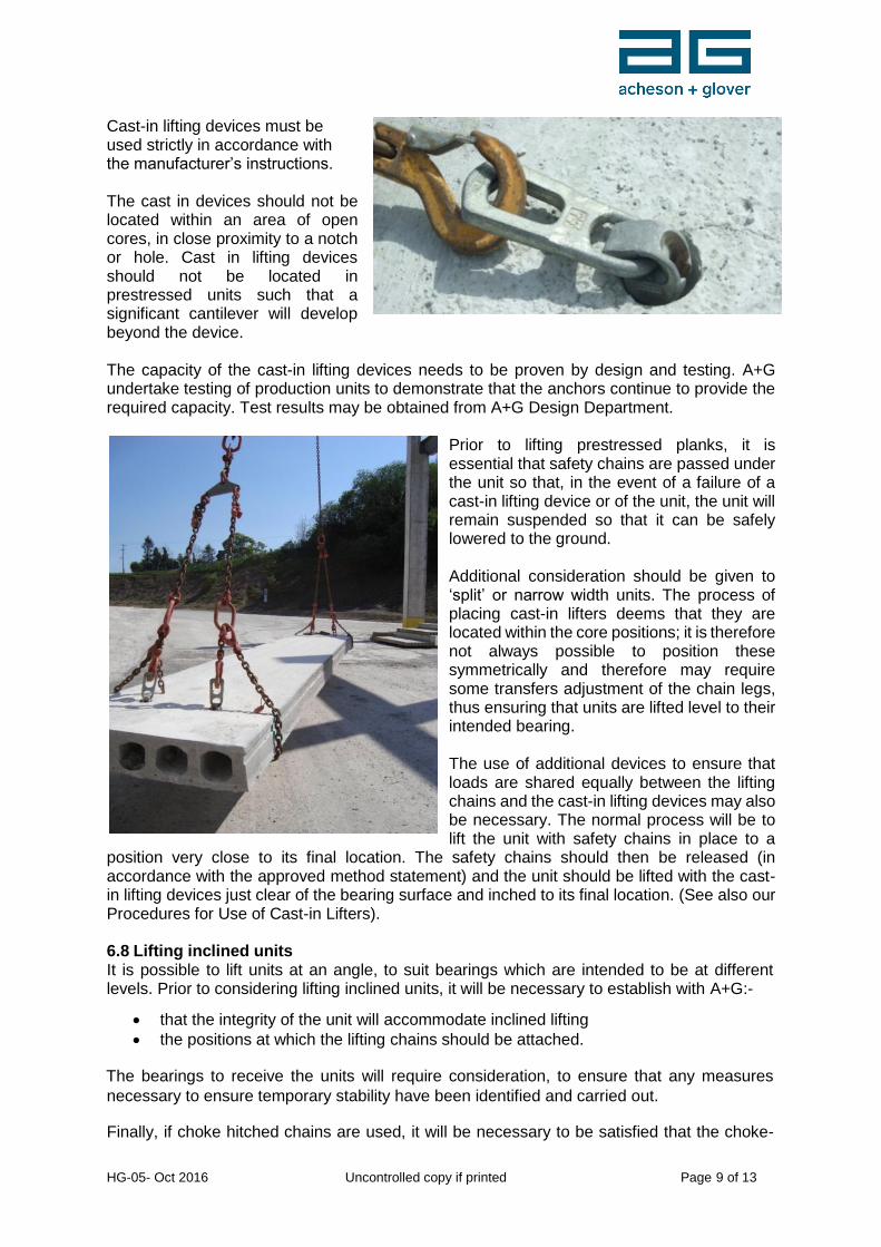
Cast-in lifting devices must be used strictly in accordance with the manufacturer’s instructions. The cast in devices should not be located within an area of open cores, in close proximity to a notch or hole. Cast in lifting devices should not be located in prestressed units such that a significant cantilever will develop beyond the device. The capacity of the cast-in lifting devices needs to be proven by design and testing. A+G undertake testing of production units to demonstrate that the anchors continue to provide the required capacity. Test results may be obtained from A+G Design Department.
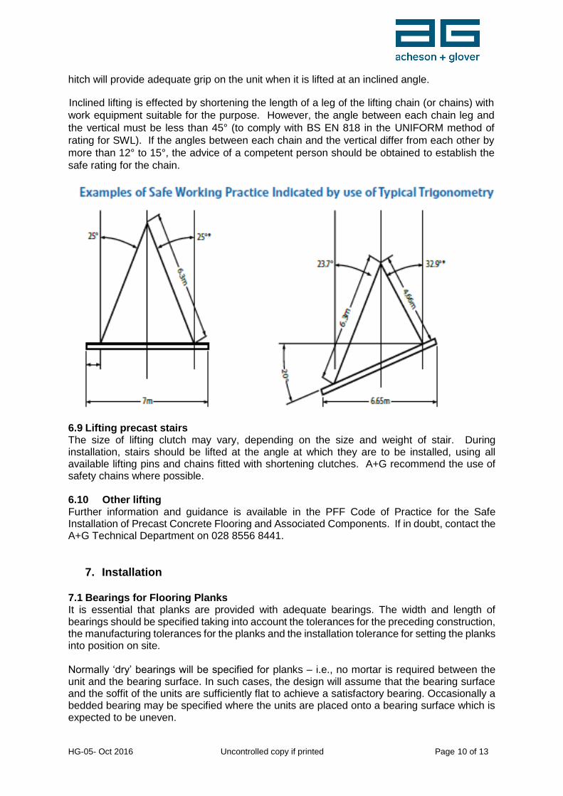
Prior to lifting prestressed planks, it is essential that safety chains are passed under the unit so that, in the event of a failure of a cast-in lifting device or of the unit, the unit will remain suspended so that it can be safely lowered to the ground. Additional consideration should be given to ‘split’ or narrow width units. The process of placing cast-in lifters deems that they are located within the core positions; it is therefore not always possible to position these symmetrically and therefore may require some transfers adjustment of the chain legs, thus ensuring that units are lifted level to their intended bearing. The use of additional devices to ensure that loads are shared equally between the lifting chains and the cast-in lifting devices may also be necessary. The normal process will be to lift the unit with safety chains in place to a
position very close to its final location. The safety chains should then be released (in accordance with the approved method statement) and the unit should be lifted with the cast-in lifting devices just clear of the bearing surface and inched to its final location. (See also our Procedures for Use of Cast-in Lifters). 6.8 Lifting inclined units It is possible to lift units at an angle, to suit bearings which are intended to be at different levels. Prior to considering lifting inclined units, it will be necessary to establish with A+G:-
that the integrity of the unit will accommodate inclined lifting
the positions at which the lifting chains should be attached. The bearings to receive the units will require consideration, to ensure that any measures
necessary to ensure temporary stability have been identified and carried out. Finally, if choke hitched chains are used, it will be necessary to be satisfied that the choke-
HG-05- Oct 2016 Uncontrolled copy if printed Page 10 of 13
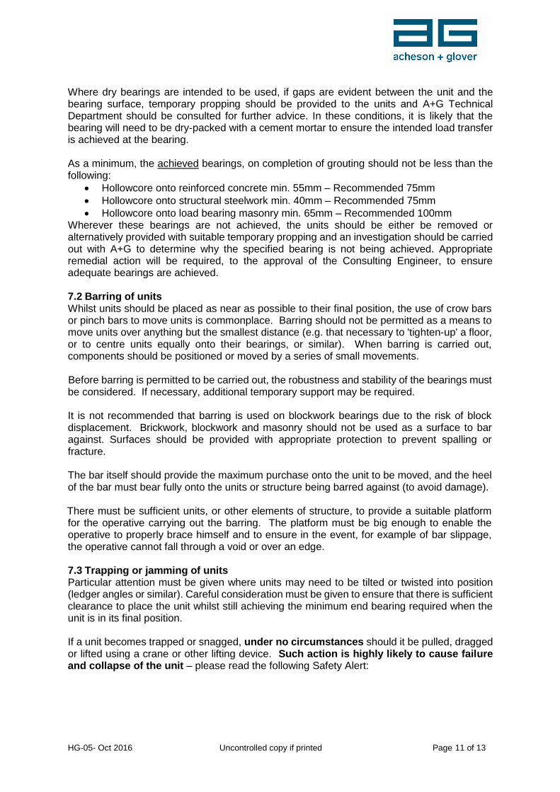
hitch will provide adequate grip on the unit when it is lifted at an inclined angle. Inclined lifting is effected by shortening the length of a leg of the lifting chain (or chains) with
work equipment suitable for the purpose. However, the angle between each chain leg and
the vertical must be less than 45° (to comply with BS EN 818 in the UNIFORM method of
rating for SWL). If the angles between each chain and the vertical differ from each other by
more than 12° to 15°, the advice of a competent person should be obtained to establish the
safe rating for the chain.
6.9 Lifting precast stairs The size of lifting clutch may vary, depending on the size and weight of stair. During installation, stairs should be lifted at the angle at which they are to be installed, using all available lifting pins and chains fitted with shortening clutches. A+G recommend the use of safety chains where possible. 6.10 Other lifting Further information and guidance is available in the PFF Code of Practice for the Safe Installation of Precast Concrete Flooring and Associated Components. If in doubt, contact the A+G Technical Department on 028 8556 8441.
7. Installation 7.1 Bearings for Flooring Planks It is essential that planks are provided with adequate bearings. The width and length of bearings should be specified taking into account the tolerances for the preceding construction, the manufacturing tolerances for the planks and the installation tolerance for setting the planks into position on site. Normally ‘dry’ bearings will be specified for planks – i.e., no mortar is required between the unit and the bearing surface. In such cases, the design will assume that the bearing surface and the soffit of the units are sufficiently flat to achieve a satisfactory bearing. Occasionally a bedded bearing may be specified where the units are placed onto a bearing surface which is expected to be uneven.
HG-05- Oct 2016 Uncontrolled copy if printed Page 11 of 13
Where dry bearings are intended to be used, if gaps are evident between the unit and the bearing surface, temporary propping should be provided to the units and A+G Technical Department should be consulted for further advice. In these conditions, it is likely that the bearing will need to be dry-packed with a cement mortar to ensure the intended load transfer is achieved at the bearing. As a minimum, the achieved bearings, on completion of grouting should not be less than the following:
Hollowcore onto reinforced concrete min. 55mm – Recommended 75mm
Hollowcore onto structural steelwork min. 40mm – Recommended 75mm
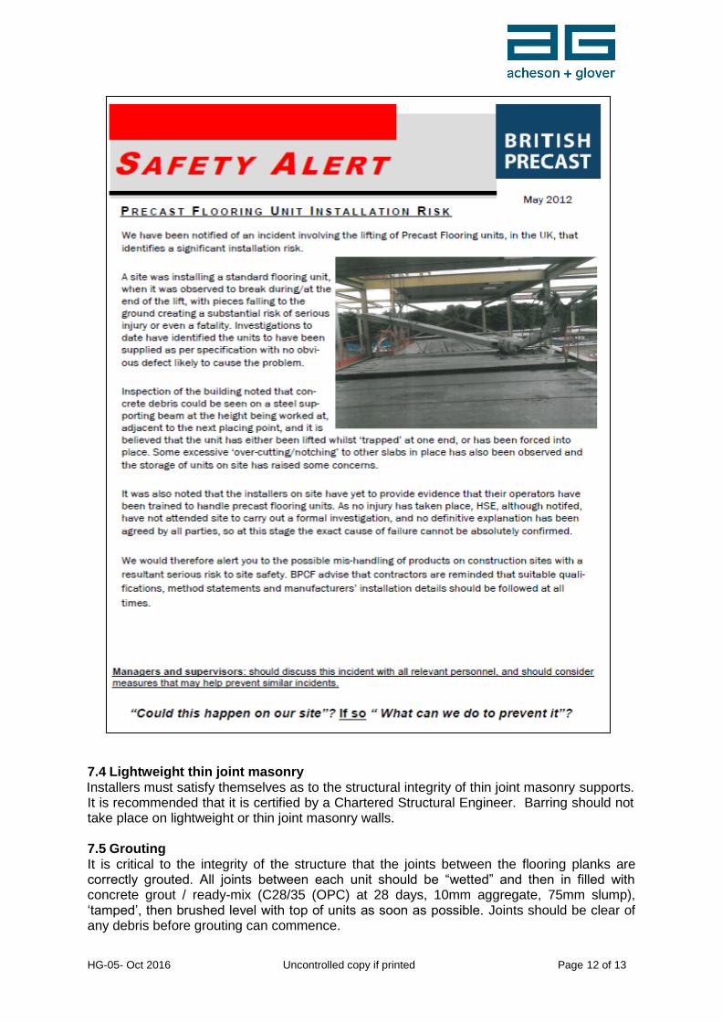
Hollowcore onto load bearing masonry min. 65mm – Recommended 100mm Wherever these bearings are not achieved, the units should be either be removed or alternatively provided with suitable temporary propping and an investigation should be carried out with A+G to determine why the specified bearing is not being achieved. Appropriate remedial action will be required, to the approval of the Consulting Engineer, to ensure adequate bearings are achieved. 7.2 Barring of units Whilst units should be placed as near as possible to their final position, the use of crow bars or pinch bars to move units is commonplace. Barring should not be permitted as a means to move units over anything but the smallest distance (e.g. that necessary to 'tighten-up' a floor, or to centre units equally onto their bearings, or similar). When barring is carried out, components should be positioned or moved by a series of small movements. Before barring is permitted to be carried out, the robustness and stability of the bearings must be considered. If necessary, additional temporary support may be required. It is not recommended that barring is used on blockwork bearings due to the risk of block displacement. Brickwork, blockwork and masonry should not be used as a surface to bar against. Surfaces should be provided with appropriate protection to prevent spalling or fracture. The bar itself should provide the maximum purchase onto the unit to be moved, and the heel of the bar must bear fully onto the units or structure being barred against (to avoid damage). There must be sufficient units, or other elements of structure, to provide a suitable platform for the operative carrying out the barring. The platform must be big enough to enable the operative to properly brace himself and to ensure in the event, for example of bar slippage, the operative cannot fall through a void or over an edge. 7.3 Trapping or jamming of units Particular attention must be given where units may need to be tilted or twisted into position (ledger angles or similar). Careful consideration must be given to ensure that there is sufficient clearance to place the unit whilst still achieving the minimum end bearing required when the unit is in its final position. If a unit becomes trapped or snagged, under no circumstances should it be pulled, dragged or lifted using a crane or other lifting device. Such action is highly likely to cause failure and collapse of the unit – please read the following Safety Alert:
HG-05- Oct 2016 Uncontrolled copy if printed Page 12 of 13
7.4 Lightweight thin joint masonry Installers must satisfy themselves as to the structural integrity of thin joint masonry supports. It is recommended that it is certified by a Chartered Structural Engineer. Barring should not take place on lightweight or thin joint masonry walls. 7.5 Grouting It is critical to the integrity of the structure that the joints between the flooring planks are correctly grouted. All joints between each unit should be “wetted” and then in filled with concrete grout / ready-mix (C28/35 (OPC) at 28 days, 10mm aggregate, 75mm slump), ‘tamped’, then brushed level with top of units as soon as possible. Joints should be clear of any debris before grouting can commence.
HG-05- Oct 2016 Uncontrolled copy if printed Page 13 of 13
Loading out of the floor, including building materials etc, must be avoided until the grout has cured. In any case the designed floor loading must NOT be exceeded. Where ‘weep holes’ are provided to the underside of cores to release any trapped water, the contractor is responsible for both keeping them clear and making good thereafter. All traffic, including pedestrian, should be kept to an absolute minimum, both on top and directly beneath the installed area until such time as the floor has been grouted and fully cured.
8. For more information …
8.1 Precast Flooring Federation Code of Practice for the Safe Erection of Precast Concrete Flooring and Associated Components, available at:
http://precastfloors.info/publications/publicationscop.html 8.2 British Precast – Safety Alert May ‘12 8.3 A+G Technical Department, telephone 028 8556 8441
Disclaimer: This document is intended as a guide only. Specific design or construction requirements may influence handling arrangements, and contractors should satisfy themselves as to the risks and methods used. Acheson & Glover Precast Limited accept no liability for actions or inactions or loss or damage by any party as a result of providing these guidelines.