hollowcore guide 2010
DESCRIPTION
hollowcore guideTRANSCRIPT
6 "
8 "
10 "
12 "
16 "
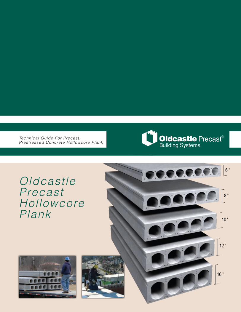
Technical Guide For Precast, Prestressed Concrete Hol lowcore Plank
Oldcast le PrecastHol lowcore Plank
Building Systems

Building Systems
Table of ContentsIntroduction......................................... 1
Manufacturing Process ....................... 1
Load Table Design Criteria .................. 1
Plank Design Considerations .............. 1
Fire Ratings ......................................... 2
Sound Ratings..................................... 2
Tolerances ........................................... 3
Load Tables ..................................4 - 17
Details ........................................18 - 24
Technical Guide For Precast, Prestressed Concrete Hol lowcore Plank
Oldcastle PrecastHollowcore Plank

Oldcastle Precast Hollowcore Plank Technical Guide | 1www.oldcastlesystems.com
IntroductionThe purpose of this technical guide is to provide assistance in select-
ing and detailing precast concrete hollowcore plank manufactured by Oldcastle Precast, Inc. Additional information and standard specifica-tions are available at oldcastlesystems.com
The load tables presented herein are intended as a guide only. Final design is determined by our engineering department based on infor-mation presented in the final plans and specifications. To ensure the optimum selection for your application, please contact us for assistance.
Although care has been taken to provide the most accurate data pos-sible, Oldcastle Precast, Inc. does not assume responsibility for errors and omissions.
The Manufacturing ProcessElematic® is a machine extruded, precast, prestressed hollowcore
plank. The planks are manufactured on 500-foot-long beds in standard widths of 48 inches and thickness of 6, 8, 10, 12 and 16 inches. High strength prestressing strands are cast into the planks at the spacing and location required for the given span, loading and fire cover conditions. The planks are cut to length for each project using a diamond-blade saw. After the planks are cut, they are removed from the casting beds and placed into storage.
All Elematic® materials equal or exceed the requirements of applicable ASTM specifications. The concrete mix is designed to have release strength of 3,000 psi or 3,500 psi, and a 28-day compressive strength of 5,000 psi. The prestressing strands are uncoated, seven wire, low relaxation with a minimum ultimate strength of 270 ksi.
Load Table Design CriteriaThe tables herein list allowable live loads in pounds per square foot for
uniformly distributed loading. Non-uniform loading conditions resulting from point loads, line loads, openings and cantilevers require special design consideration.
The allowable load is usually governed by the ultimate capacity of the section. As a design aid, the ultimate moment capacities in governing criterion for short spans may be the horizontal shear stress between the plank and the topping.
Allowable live loads for long-span, heavily reinforced sections are limited to loads that result in a bottom-tension stress equal to the crack-ing stress. Loads beyond this limit may result in deflections that exceed the allowable value set forth in the ACI code.
The load tables are based on a plank concrete strength of 5,000 psi. Tables for topped sections are based on a topping strength of 3,500 psi and minimum thickness of 2 inches.
Maximum spans and loads shown are not absolutes. Longer spans or heavier loads may be achieved under certain conditions or different criteria than assumed in the tables. Contact us if you need assistance.
Plank Design ConsiderationsThe following items will affect the selection of appropriate plank sizes
and should be carefully reviewed by the Architect/Engineer while devel-oping the plans and specifications for a project:
Fire RatingThe fire rating requirement should be clearly specified in the contract •documents.
Loading ConditionsSpecify all uniform loading requirements on structural plans.•Identify line and point loads resulting from bearing walls, masonry •walls, face brick, columns, mechanical equipment, etc.Identify diaphragm forces and lateral loads resulting from wind or •earth pressures.Review roof plans for vertical protrusions such as parapets, pent-•houses and adjacent buildings that could require designing for snow drift loads.Plank supporting stairs require special loading considerations.•Large openings or closely spaced groups of smaller openings will •reduce the plank load carrying capacity.
ToppingSpecify whether or not concrete topping is to be composite. Compos-•ite action requires the topping to be bonded to the top surface of the plank. Topping separated by a vapor barrier or insulation is non-composite and must be considered a superimposed load.Large cambers resulting from long spans and/or heavy loads will •affect the quantity of topping, assuming a level floor is required. Two inches of composite topping at mid span is minimal, and additional thickness at the ends of the plank may be required to maintain level floor elevations.
CamberCamber is inherent in all prestressed products. It is the result of the •eccentric prestress force required to resist design loads, and cannot be designed in, out, or to an exact number. The amount of camber will depend upon the span, design loads and thickness of plank. Planks stored in the yard for more than 6 weeks, usually due to construction schedule changes, will experience more camber growth.Adjacent plank of dissimilar length, strand pattern or with openings •will have inherent camber differences.

2 | Oldcastle Precast Hollowcore Plank Technical Guide www.oldcastlesystems.com
Fire RatingFire rating specifications are as important as all other design parameters.
Plank rating requirements are determined by the Architect or Engineer of Record, who is also responsible for establishing the fire rating criteria for the total project.
Three methods generally used in the Northeast for determining hollowcore plank fire-resistive ratings are:
1. 2006 International Building Code2. Rational analysis as defined by PCI MNL 124, “Design for Fire
Resistance of Precast Concrete”3. Underwriters Laboratories Fire Resistive Ratings4. MEA product approval (New York City only)
International Building Code “IBC” Fire RatingThe IBC code prescribes fire ratings to any hollowcore plank section.
Since 2000, the IBC code has replaced the BOCA, SBC and UBC model codes in many states. The two criteria that are measured to determine the fire rating are:
1. Equivalent concrete thickness – 4.6" inches is required for 2 hrs2. Bottom strand cover – ¾" cover is required for 2 hrs (restrained
condition)
Underwriters Laboratories Fire Resistive RatingsPrior to codes including prescriptive fire-endurance rating methods,
fire tests provided the primary source of ratings classifications. While some plank sections were fire tested, others can be evaluated by UL to qualify for existing UL numbers.
The table below lists the UL ratings available with Elematic® plank. Note that these ratings are dependent upon whether or not the ends of the planks are restrained. Determination of the restraint must be made by the Architect or the Engineer of Record, as it is primarily a function of the support structure.
Fire Ratings by Rational AnalysisPCI MNL 124 defines the “rational analysis” method for determining
the fire rating of precast, prestressed members. It is useful when a fire rating cannot be obtained by either of the two previous methods. Actual practice has shown that this method is very conservative and that the span of the hollowcore plank will have to be reduced (approx. 10% to 20%) to achieve the same fire rating from both IBC and UL.
In using this method, the reduced strength of the prestressed strands at elevated temperatures is determined and the resulting moment capacities are compared to that required for service loads. Strand
temperatures are based on the amount of concrete cover and the standard fire exposure as defined by the time-temperature relationship specified in ASTM E119. Fire ratings will also be improved if the plank assembly is restrained against thermal expansion. It should be noted that the only universally accepted definition of full restraint is an interior bay of a multi-bay building.
Sound RatingsThe following tables contain values for the Sound Transmission Class
(STC) and the Impact Insulations Class (IIC) of various floor systems utilizing Elematic® hollowcore plank.
Sound Transmission Class (STC)The values for the
Sound Transmission Class were deter-mined by tests which were in accordance with ASTM E90. The STC is a measure (in decibels) of the ease at which air-borne sound is transmit-ted through a floor system. The larger the value of the STC for a given system, the greater the sound insulation.
Impact Insulation Class (IIC)
The values for the Impact Insulation Class (IIC) were determined by tests which were in accordance with ASTM ES492. The Impact Insulation Class is the resistance to impact noise transmission and is highly dependent on the floor surface and structural connection details. As with the STC, the higher IIC values are more desirable.
UL Number
Rating (Hour) PlankThickness
(inch)
ToppingThickness
(inch)Restrained Unrestrained
J994 1½ 1½ 8,10,12 0
J994 2 1½ 8,10,12 ½ Gypcrete
J994 3 1½ 8,10,12 21/8 Topping
J994 4 1½ 8,10,12 33/8 Topping
Impact Insulation Class (IIC)
Types of Floor Systems Rating
8" Hollowcore Plank 28
8" Hollowcore Plank + ½" wood block flooring adhered directly 47
8" Hollowcore Plank + 0.058" vinyl tile 50
8" Hollowcore Plank + quarry tile w/reinforced mortar bed with 0.4" nylon and carbon black spinneret matting.
54
8" Hollowcore Plank + pad & carpet 73
Add Acoustical Ceiling +6
Sound Transmission Class (STC)
6" Elematic® 49
6" Elematic® + 2" Topping 53
8" Elematic® 51
8" Elematic® + 2" Topping 54
H8" Heavy Elematic® 51
H8" Heavy Elematic® + 2" Topping 55
10" Elematic® 52
10" Elematic® + 2" Topping 56
12" Elematic® 54
12" Elematic® + 2" Topping 57
16" Elematic® 56
16" Elematic® + 2" Topping 59
Oldcastle Precast Hollowcore Plank Technical Guide | 3www.oldcastlesystems.com
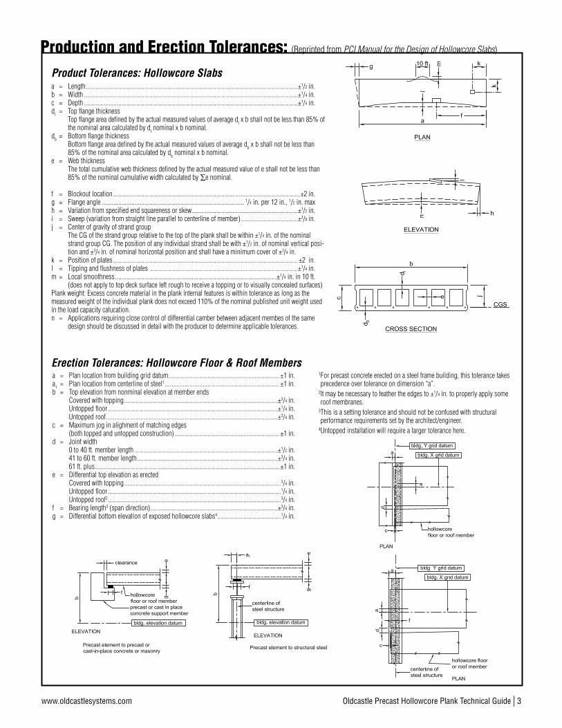
Production and Erection Tolerances: (Reprinted from PCI Manual for the Design of Hollowcore Slabs)
a = Length ..................................................................................................................................±1/2 in.b = Width ...................................................................................................................................±1/4 in.c = Depth ...................................................................................................................................±1/4 in.dt = Top flange thickness Top flange area defined by the actual measured values of average dt x b shall not be less than 85% of
the nominal area calculated by dt nominal x b nominal.db = Bottom flange thickness Bottom flange area defined by the actual measured values of average db x b shall not be less than
85% of the nominal area calculated by db nominal x b nominal.e = Web thickness The total cumulative web thickness defined by the actual measured value of e shall not be less than
85% of the nominal cumulative width calculated by ∑e nominal.
f = Blockout location .................................................................................................................. ±2 in.g = Flange angle ....................................................................................... 1/4 in. per 12 in., 1/2 in. maxh = Variation from specified end squareness or skew .................................................................±1/2 in.i = Sweep (variation from straight line parallel to centerline of member) ...................................±3/8 in.j = Center of gravity of strand group The CG of the strand group relative to the top of the plank shall be within ±1/4 in. of the nominal
strand group CG. The position of any individual strand shall be with ±1/2 in. of nominal vertical posi-tion and ±3/4 in. of nominal horizontal position and shall have a minimum cover of ±3/4 in.
k = Position of plates ................................................................................................................. ±2 in.l = Tipping and flushness of plates ...........................................................................................±1/4 in.m = Local smoothness ...................................................................................................±1/4 in. in 10 ft. (does not apply to top deck surface left rough to receive a topping or to visually concealed surfaces)Plank weight: Excess concrete material in the plank internal features is within tolerance as long as the measured weight of the individual plank does not exceed 110% of the nominal published unit weight used in the load capacity calucation.n = Applications requiring close control of differential camber between adjacent membes of the same
design should be discussed in detail with the producer to determine applicable tolerances.
Product Tolerances: Hollowcore Slabs
a = Plan location from building grid datum .................................................................... ±1 in.a1 = Plan location from centerline of steel1 ...................................................................... ±1 in.b = Top elevation from nonminal elevation at member ends Covered with topping ..............................................................................................±3/4 in. Untopped floor ........................................................................................................±1/4 in. Untopped roof .........................................................................................................±3/4 in.c = Maximum jog in alighment of matching edges (both topped and untopped construction) ................................................................ ±1 in.d = Joint width 0 to 40 ft. member length ........................................................................................±1/2 in. 41 to 60 ft. member length ......................................................................................±3/4 in. 61 ft. plus ................................................................................................................. ±1 in.e = Differential top elevation as erected Covered with topping ................................................................................................3/4 in. Untopped floor ..........................................................................................................1/4 in. Untopped roof2 ..........................................................................................................3/4 in.f = Bearing length3 (span direction) ..............................................................................±3/4 in.g = Differential bottom elevation of exposed hollowcore slabs4 .......................................1/4 in.
1 For precast concrete erected on a steel frame building, this tolerance takes precedence over tolerance on dimension “a”.
2 It may be necessary to feather the edges to ±1/4 in. to properly apply some roof membranes.
3 This is a setting tolerance and should not be confused with structural performance requirements set by the architect/engineer.
4 Untopped installation will require a larger tolerance here.
Erection Tolerances: Hollowcore Floor & Roof Members
4 | Oldcastle Precast Hollowcore Plank Technical Guide www.oldcastlesystems.com
Bui
ldin
g S
yste
ms
ELEM
ATIC
® H
ollo
wco
re P
lank
3/8"
3/8"
1 3/8" 3 1/4" 1 3/8"
1 5/
8"
4'-0
"
1 1/2"1 31/32"
1 3/4"25/32"
5/16
"
1/2"
6"
5 19
/32"
5 19
/32"
5 19
/32"
5 19
/32"
5 19
/32"
5 19
/32"
5 19
/32"
5 19
/32"
1 5/
8"
1 21
/32" 4
17/3
2"17
/32"
R2 23/32"
31/32"4 1/8"7/8"
INCL
UDES
THE
LIV
E LO
AD P
LUS
ANY
DEAD
LOA
D TH
AT IS
ADD
ITIO
NAL
TO T
HE W
EIGH
T OF
THE
BAR
E GR
OUTE
D PL
ANKS
IN P
LACE
UNIF
ORM
LY D
ISTR
IBUT
ED S
UPER
IMPO
SED*
LOA
D IN
LBS
. PER
SQ.
FT.
17pe
r Uni
t16
1514
1311
1012
5. V
alue
s to
the
left
and
belo
w th
e he
avy
step
ped
line
are
cont
rolle
d by
she
ar.
mat
eria
ls in
the
prop
osed
stru
ctur
e.so
that
thes
e fa
ctor
s ar
e co
mpa
tible
with
the
cont
iguo
usan
d/or
eng
inee
r for
the
cont
empl
ated
load
ing
and
span
defle
ctio
n m
ust a
lway
s be
inve
stig
ated
by
the
arch
itect
,4.
The
tabl
e in
dica
tes
max
imum
saf
e lo
ads.
Cam
ber a
nd
3. F
or lo
nger
spa
ns, h
eavi
er lo
ads,
or s
peci
al c
ondi
tions
,
2. F
or c
ompl
ete
and
deta
iled
calc
ulat
ions
con
sult
cons
ult O
ldca
stle
Pre
cast
.
Oldc
astle
Pre
cast
.
1. D
esig
n St
anda
rd: A
CI 3
18-2
005
NOTE
S
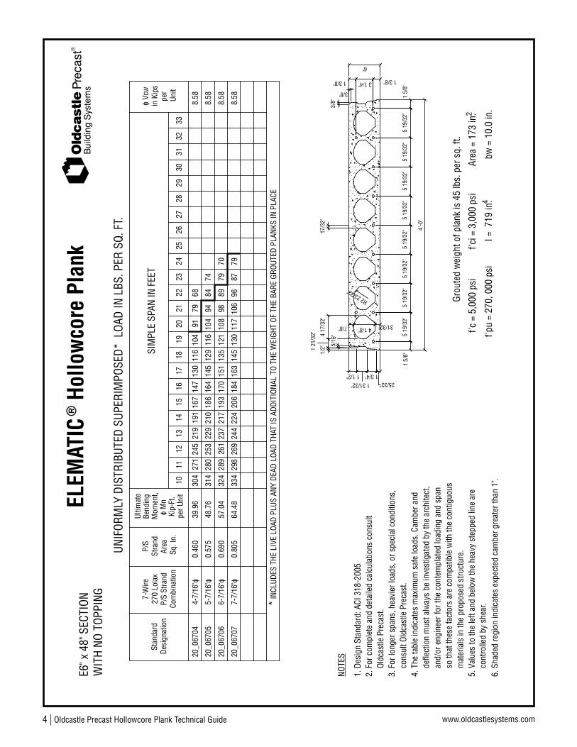
*
WIT
H NO
TOP
PING
E6" x
48"
SEC
TION
Desi
gnat
ion
Stan
dard
Com
bina
tion
P/S
Stra
nd
7-W
ire27
0 Lo
lax
P/S
Area
Sq. I
n.
Stra
nd
Kip-
Ft.
o M
n M
omen
t,Be
ndin
gUl
timat
e
3332
3130
2928
2726
2524
2322
2120
1918
f'ci =
3,0
00 p
si
I = 7
19 in
.
Grou
ted
wei
ght o
f pla
nk is
45
lbs.
per
sq.
ft.
f'pu
= 27
0, 0
00 p
si
f'c =
5,0
00 p
siAr
ea =
173
in.
bw =
10.
0 in
.4
2
8.58
SIM
PLE
SPAN
IN F
EET
o Vc
win
Kip
spe
rUn
it
130
4-7/
16"o
20_0
6704
304
0.46
039
.96
245
271
219
167
191
147
116
104
91
5-7/
16"o
20_0
6705
0.57
548
.76
7-7/
16"o
20_0
6707
0.80
564
.48
145
314
253
280
229
186
210
164
129
104
116
9484
163
334
269
298
244
206
224
184
145
130
117
9610
687
79
8.58
8.58
6. S
hade
d re
gion
indi
cate
s ex
pect
ed c
ambe
r gre
ater
than
1".
8.58
151
20_0
6706
324
0.69
057
.04
261
289
237
193
217
170
135
108
121
8998
796-
7/16
"o
7968
74
70

Oldcastle Precast Hollowcore Plank Technical Guide | 5www.oldcastlesystems.com Oldcastle Precast Hollowcore Plank Technical Guide | 5www.oldcastlesystems.com
Bui
ldin
g S
yste
ms
ELEM
ATIC
® H
ollo
wco
re P
lank
2"
3/8"
4'-0
"
1 5/
8"
1 3/8"3 1/4"1 3/8"
3/8"
5 19
/32"
4 17
/32"
1 21
/32"
1/2" 5/
16" 5
19/3
2"1
5/8"
25/32" 1 3/4"
1 31/32" 1 1/2"
7/8" 4 1/8" 31/32"
5 19
/32"
R2 23/32"
5 19
/32"
17/3
2"
5 19
/32"
5 19
/32"
5 19
/32"
5 19
/32"
6"
Grou
ted
wei
ght o
f pla
nk &
2" t
oppi
ng is
45+
25 =
70
lbs.
per
sq.
ft.
f'c =
5,0
00 p
si
f'pu
= 27
0,00
0 ps
iIc
= 1
,580
in.
f'ci =
3,0
00 p
si 4bw
= 1
0.0
in.
Area
= 1
73 in
.2
3332
3129
2830
2726
2423
2520
2119
1822
1615
1413
1110
per U
nit
1217
INCL
UDES
THE
LIV
E LO
AD P
LUS
ANY
DEAD
LOA
D TH
AT IS
ADD
ITIO
NAL
TO T
HE W
EIGH
T OF
THE
BAR
E GR
OUTE
D PL
ANKS
& T
OPPI
NG*
12.3
0
270
Lola
x7-
Wire
P/S
Stra
ndCo
mbi
natio
n
Stan
dard
Desi
gnat
ion
Ultim
ate
Bend
ing
Mom
ent,
Kip-
Ft.
o M
n
P/S
Stra
nd
Sq. I
n.Ar
ea
o Vc
win
Kip
sSI
MPL
E SP
AN IN
FEE
T
Unit
per
UNIF
ORM
LY D
ISTR
IBUT
ED S
UPER
IMPO
SED*
LOA
D IN
LBS
. PER
SQ.
FT.
E6" x
48"
SEC
TION
WIT
H 2"
TOP
PING
(350
0 PS
I)
176
404
57.3
636
032
329
323
226
720
110
515
512
885
70.0
0
93.6
4
199
412
367
299
330
250
273
228
136
175
155
114
222
428
381
343
311
260
284
240
157
200
177
140
9578
125
7510
790
12.3
0
12.3
020
842
082
.08
374
305
336
255
278
235
143
183
162
105
125
8873
12.3
0
4-7/
16"o
20_0
6704
T0.
460
5-7/
16"o
20_0
6705
T0.
575
7-7/
16"o
20_0
6707
T0.
805
20_0
6706
T0.
690
6-7/
16"o
5. V
alue
s to
the
left
and
belo
w th
e he
avy
step
ped
line
are
cont
rolle
d by
she
ar.
mat
eria
ls in
the
prop
osed
stru
ctur
e.so
that
thes
e fa
ctor
s ar
e co
mpa
tible
with
the
cont
iguo
usan
d/or
eng
inee
r for
the
cont
empl
ated
load
ing
and
span
defle
ctio
n m
ust a
lway
s be
inve
stig
ated
by
the
arch
itect
,4.
The
tabl
e in
dica
tes
max
imum
saf
e lo
ads.
Cam
ber a
nd
3. F
or lo
nger
spa
ns, h
eavi
er lo
ads,
or s
peci
al c
ondi
tions
,
2. F
or c
ompl
ete
and
deta
iled
calc
ulat
ions
con
sult
cons
ult O
ldca
stle
Pre
cast
.
Oldc
astle
Pre
cast
.
NOTE
S
6. S
hade
d re
gion
indi
cate
s ex
pect
ed c
ambe
r gre
ater
than
1".
68
59
1. D
esig
n St
anda
rd: A
CI 3
18-2
005

6 | Oldcastle Precast Hollowcore Plank Technical Guide www.oldcastlesystems.com
Bui
ldin
g S
yste
ms
ELEM
ATIC
® H
ollo
wco
re P
lank
21/3
2"1
11/3
2"2
11/3
2"6
3/32
"
1/2"
4'-0
"
7 7/
16"
7 7/
16"
7 7/
16"
7 1/
8"5 29/32" 31/32"
25/32"3 3/4"
2"5/16
"
1 31/32"1 1/2"
R3 3/16"
1 1/8"
8"
7 1/
8"7
7/16
"2"
1 3/8"5 1/8"1 1/2"
3/8"
3/8"
INCL
UDES
THE
LIV
E LO
AD P
LUS
ANY
DEAD
LOA
D TH
AT IS
ADD
ITIO
NAL
TO T
HE W
EIGH
T OF
THE
BAR
E GR
OUTE
D PL
ANKS
IN P
LACE
UNIF
ORM
LY D
ISTR
IBUT
ED S
UPER
IMPO
SED*
LOA
D IN
LBS
. PER
SQ.
FT.
17pe
r Uni
t16
1514
1311
1012
*
WIT
H NO
TOP
PING
E8" x
48"
SEC
TION
Desi
gnat
ion
Stan
dard
Com
bina
tion
P/S
Stra
nd
7-W
ire27
0 Lo
lax
P/S
Area
Sq. I
n.
Stra
nd
Kip-
Ft.
o M
n M
omen
t,Be
ndin
gUl
timat
e
3332
3130
2928
2726
2524
2322
2120
1918
f'ci =
3,0
00 p
si
I = 1
,580
in.
Grou
ted
wei
ght o
f pla
nk is
54
lbs.
per
sq.
ft.
f'pu
= 27
0, 0
00 p
si
f'c =
5,0
00 p
siAr
ea =
207
in.
bw =
10.
0 in
.4
2
12.3
0
12.3
0
12.3
0
SIM
PLE
SPAN
IN F
EET
o Vc
win
Kip
spe
rUn
it
204
4-7/
16"o
20_0
8704
196
0.46
058
.88
348
386
316
260
289
230
182
163
143
112
126
99
5-7/
16"o
20_0
8705
0.57
572
.52
226
446
359
398
326
275
298
254
112
182
202
164
135
148
123
103
91
6-7/
16"o
20_0
8706
0.69
085
.44
243
460
370
411
337
283
308
262
135
221
199
163
179
148
123
113
104
8696
251
6-1/
2"o
20_0
8806
473
0.91
810
9.88
381
423
347
292
317
270
135
217
234
196
162
178
148
124
105
114
8997
8312
.30
74
260
7-1/
2"o
20_0
8807
489
1.07
112
4.60
394
437
358
302
328
280
146
227
242
211
175
192
160
134
114
124
9710
590
12.3
084
78
251
7-7/
16"o
20_0
8707
473
0.80
597
.96
381
423
347
292
317
270
126
226
204
184
151
167
138
9811
610
681
9073
12.3
0
5. V
alue
s to
the
left
and
belo
w th
e he
avy
step
ped
line
are
cont
rolle
d by
she
ar.
mat
eria
ls in
the
prop
osed
stru
ctur
e.so
that
thes
e fa
ctor
s ar
e co
mpa
tible
with
the
cont
iguo
usan
d/or
eng
inee
r for
the
cont
empl
ated
load
ing
and
span
defle
ctio
n m
ust a
lway
s be
inve
stig
ated
by
the
arch
itect
,4.
The
tabl
e in
dica
tes
max
imum
saf
e lo
ads.
Cam
ber a
nd
3. F
or lo
nger
spa
ns, h
eavi
er lo
ads,
or s
peci
al c
ondi
tions
,
2. F
or c
ompl
ete
and
deta
iled
calc
ulat
ions
con
sult
cons
ult O
ldca
stle
Pre
cast
.
Oldc
astle
Pre
cast
.
NOTE
S
6. S
hade
d re
gion
indi
cate
s ex
pect
ed c
ambe
r gre
ater
than
1".
8777
68
8171
7769
65
1. D
esig
n St
anda
rd: A
CI 3
18-2
005

Oldcastle Precast Hollowcore Plank Technical Guide | 7www.oldcastlesystems.com
Bui
ldin
g S
yste
ms
ELEM
ATIC
® H
ollo
wco
re P
lank 7
7/16
"
4'-0
"
21/3
2"
1 1/8"
R3 3/16"
1 1/2"1 31/32"
5/16
"
2"
3 3/4"25/32"
31/32"5 29/32" 7 1/
8"7
7/16
"
1/2"
6 3/
32"
2 11
/32"
1 11
/32"
3/8"
3/8"
1 1/2" 5 1/8" 1 3/8"
2"7
7/16
"7
1/8"
8"
7 7/
16"
2"
Grou
ted
wei
ght o
f pla
nk &
2" t
oppi
ng is
54+
25 =
79
lbs.
per
sq.
ft.
f'c =
5,0
00 p
si
f'pu
= 27
0,00
0 ps
iIc
= 3
,072
in.
f'ci =
3,0
00 p
si 4bw
= 1
0.0
in.
Area
= 2
07 in
.2
3332
3129
2830
2726
2423
2520
2119
1822
1615
1413
1110
per U
nit
1217
INCL
UDES
THE
LIV
E LO
AD P
LUS
ANY
DEAD
LOA
D TH
AT IS
ADD
ITIO
NAL
TO T
HE W
EIGH
T OF
THE
BAR
E GR
OUTE
D PL
ANKS
& T
OPPI
NG*
16.0
1
16.0
1
16.0
1
270
Lola
x7-
Wire
P/S
Stra
ndCo
mbi
natio
n
Stan
dard
Desi
gnat
ion
Ultim
ate
Bend
ing
Mom
ent,
Kip-
Ft.
o M
n
P/S
Stra
nd
Sq. I
n.Ar
ea
o Vc
win
Kip
sSI
MPL
E SP
AN IN
FEE
T
Unit
per
UNIF
ORM
LY D
ISTR
IBUT
ED S
UPER
IMPO
SED*
LOA
D IN
LBS
. PER
SQ.
FT.
E8" x
48"
SEC
TION
WIT
H 2"
TOP
PING
(350
0 PS
I)
301
577
141.
8051
446
241
935
138
332
424
528
026
120
823
018
812
817
015
514
199
113
8674
16.0
1
265
243
76.2
821
343
639
533
136
130
117
923
420
513
815
711
910
083
263
248
93.7
249
540
344
533
836
828
918
823
420
915
217
013
195
112
80
301
577
126.
4051
446
241
935
238
332
523
828
026
119
321
417
415
814
312
811
197
8371
312
295
566
110.
3650
445
341
134
537
531
823
227
425
618
720
816
910
415
313
912
116
.01
9076
4-7/
16"o
20_0
8704
T0.
460
5-7/
16"o
20_0
8705
T0.
575
6-7/
16"o
20_0
8706
T0.
690
6-1/
2"o
20_0
8806
T0.
918
308
589
161.
5652
547
242
836
039
133
225
128
626
822
223
520
514
118
616
915
411
812
910
592
8016
.01
7-1/
2"o
20_0
8807
T1.
071
7-7/
16"o
20_0
8707
T0.
805
5. V
alue
s to
the
left
and
belo
w th
e he
avy
step
ped
line
are
cont
rolle
d by
she
ar.
mat
eria
ls in
the
prop
osed
stru
ctur
e.so
that
thes
e fa
ctor
s ar
e co
mpa
tible
with
the
cont
iguo
usan
d/or
eng
inee
r for
the
cont
empl
ated
load
ing
and
span
defle
ctio
n m
ust a
lway
s be
inve
stig
ated
by
the
arch
itect
,4.
The
tabl
e in
dica
tes
max
imum
saf
e lo
ads.
Cam
ber a
nd
3. F
or lo
nger
spa
ns, h
eavi
er lo
ads,
or s
peci
al c
ondi
tions
,
2. F
or c
ompl
ete
and
deta
iled
calc
ulat
ions
con
sult
cons
ult O
ldca
stle
Pre
cast
.
Oldc
astle
Pre
cast
.
NOTE
S
6. S
hade
d re
gion
indi
cate
s ex
pect
ed c
ambe
r gre
ater
than
1".
68
67
1. D
esig
n St
anda
rd: A
CI 3
18-2
005
8 | Oldcastle Precast Hollowcore Plank Technical Guide www.oldcastlesystems.com
Bui
ldin
g S
yste
ms
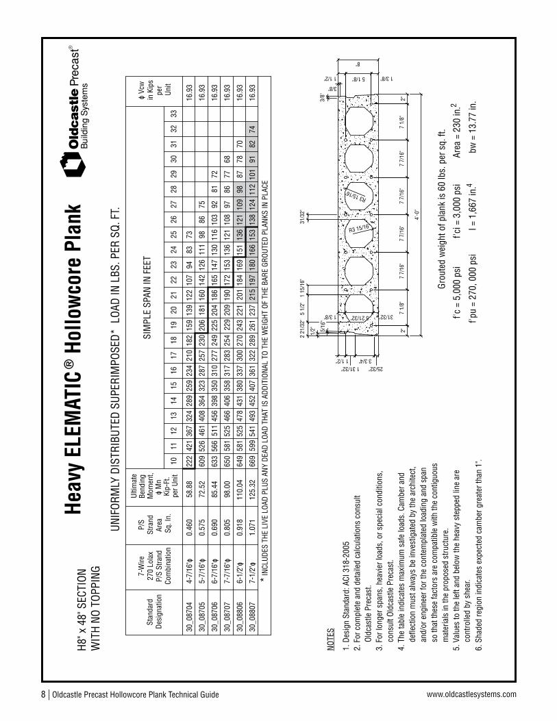
Heav
y EL
EMAT
IC® H
ollo
wco
re P
lank
3/8"
3/8"
1 1/2" 5 1/8" 1 3/8"
2"
4'-0
"
7 7/
16"
1 3/8" 7 1/
8"
5 1/
2"
1 1/2"1 31/32"
3 3/4"25/32"
5/16
"
2"31/32"5 21/32"
1/2"
2 21
/32"
7 7/
16"
1 15
/16"
7 7/
16"
7 7/
16"
31/3
2"
7 1/
8"
8"
R3 15/16"
R3 15/16"
INCL
UDES
THE
LIV
E LO
AD P
LUS
ANY
DEAD
LOA
D TH
AT IS
ADD
ITIO
NAL
TO T
HE W
EIGH
T OF
THE
BAR
E GR
OUTE
D PL
ANKS
IN P
LACE
UNIF
ORM
LY D
ISTR
IBUT
ED S
UPER
IMPO
SED*
LOA
D IN
LBS
. PER
SQ.
FT.
17pe
r Uni
t16
1514
1311
1012
*
WIT
H NO
TOP
PING
H8" x
48"
SEC
TION
Desi
gnat
ion
Stan
dard
Com
bina
tion
P/S
Stra
nd
7-W
ire27
0 Lo
lax
P/S
Area
Sq. I
n.
Stra
nd
Kip-
Ft.
o M
n M
omen
t,Be
ndin
gUl
timat
e
3332
3130
2928
2726
2524
2322
2120
1918
f'ci =
3,0
00 p
si
I = 1
,667
in.
Grou
ted
wei
ght o
f pla
nk is
60
lbs.
per
sq.
ft.
f'pu
= 27
0, 0
00 p
si
f'c =
5,0
00 p
siAr
ea =
230
in.
bw =
13.
77 in
.4
2
16.9
3
16.9
3
16.9
3
SIM
PLE
SPAN
IN F
EET
o Vc
win
Kip
spe
rUn
it
210
4-7/
16"o
30_0
8704
222
0.46
058
.88
367
421
324
259
289
234
182
159
139
107
122
94
5-7/
16"o
30_0
8705
0.57
572
.52
257
609
461
526
408
323
364
287
111
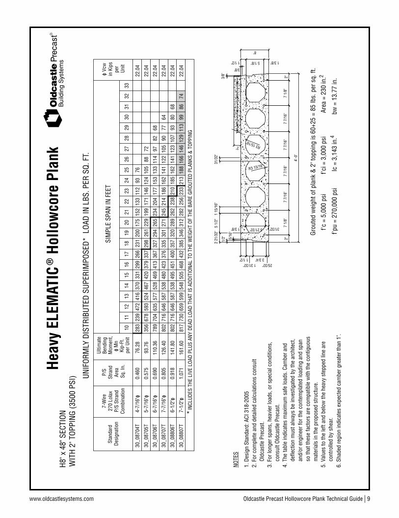
206
230
181
142
160
126
9886
6-7/
16"o
30_0
8706
0.69
085
.44
277
633
511
566
456
350
398
310
147
249
225
186
204
165
130
116
103
8192
300
6-1/
2"o
30_0
8806
649
0.91
811
0.04
525
581
478
380
431
337
151
243
270
221
184
201
169
136
109
121
8798
7816
.93
70
322
7-1/
2"o
30_0
8807
669
1.07
112
5.32
541
599
493
407
452
361
166
261
289
237
197
215
180
153
124
138
101
112
9116
.93
8274
283
7-7/
16"o
30_0
8707
650
0.80
598
.00
525
581
466
358
406
317
136
254
229
209
172
190
153
9712
110
877
8668
16.9
3
5. V
alue
s to
the
left
and
belo
w th
e he
avy
step
ped
line
are
cont
rolle
d by
she
ar.
mat
eria
ls in
the
prop
osed
stru
ctur
e.so
that
thes
e fa
ctor
s ar
e co
mpa
tible
with
the
cont
iguo
usan
d/or
eng
inee
r for
the
cont
empl
ated
load
ing
and
span
defle
ctio
n m
ust a
lway
s be
inve
stig
ated
by
the
arch
itect
,4.
The
tabl
e in
dica
tes
max
imum
saf
e lo
ads.
Cam
ber a
nd
3. F
or lo
nger
spa
ns, h
eavi
er lo
ads,
or s
peci
al c
ondi
tions
,
2. F
or c
ompl
ete
and
deta
iled
calc
ulat
ions
con
sult
cons
ult O
ldca
stle
Pre
cast
.
Oldc
astle
Pre
cast
.
NOTE
S
6. S
hade
d re
gion
indi
cate
s ex
pect
ed c
ambe
r gre
ater
than
1".
8373
75
72
1. D
esig
n St
anda
rd: A
CI 3
18-2
005
Oldcastle Precast Hollowcore Plank Technical Guide | 9www.oldcastlesystems.com
Bui
ldin
g S
yste
ms
Heav
y EL
EMAT
IC® H
ollo
wco
re P
lank
7 7/
16"
4'-0
"
25/32"3 3/4"
1 31/32"1 1/2"
5 1/
2"
7 1/
8"1 3/8" 5 21/32" 31/32"
2"5/16
"
2 21
/32"
1/2"
1 15
/16"
2"
1 3/8"5 1/8"1 1/2"
3/8"
7 7/
16"
31/3
2"
7 7/
16"
R3 15/16"
R3 15/16"
7 1/
8"7
7/16
"
8"
2"
3/8"
Grou
ted
wei
ght o
f pla
nk &
2" t
oppi
ng is
60+
25 =
85
lbs.
per
sq.
ft.
f'c =
5,0
00 p
si
f'pu
= 27
0,00
0 ps
iIc
= 3
,143
in.
f'ci =
3,0
00 p
si 4bw
= 1
3.77
in.
Area
= 2
30 in
.2
3332
3129
2830
2726
2423
2520
2119
1822
1615
1413
1110
per U
nit
1217
INCL
UDES
THE
LIV
E LO
AD P
LUS
ANY
DEAD
LOA
D TH
AT IS
ADD
ITIO
NAL
TO T
HE W
EIGH
T OF
THE
BAR
E GR
OUTE
D PL
ANKS
& T
OPPI
NG*
22.0
4
22.0
4
22.0
4
270
Lola
x7-
Wire
P/S
Stra
ndCo
mbi
natio
n
Stan
dard
Desi
gnat
ion
Ultim
ate
Bend
ing
Mom
ent,
Kip-
Ft.
o M
n
P/S
Stra
nd
Sq. I
n.Ar
ea
o Vc
win
Kip
sSI
MPL
E SP
AN IN
FEE
T
Unit
per
UNIF
ORM
LY D
ISTR
IBUT
ED S
UPER
IMPO
SED*
LOA
D IN
LBS
. PER
SQ.
FT.
H8" x
48"
SEC
TION
WIT
H 2"
TOP
PING
(350
0 PS
I)
400
802
141.
8071
664
658
749
553
845
128
935
732
023
826
221
012
318
516
214
193
107
8068
22.0
4
266
283
76.2
823
947
241
633
137
029
917
523
120
013
315
211
293
76
298
356
93.7
667
852
459
342
046
733
719
926
122
914
617
112
488
105
376
802
126.
4071
664
658
748
053
842
327
133
530
121
424
518
616
214
112
210
590
7764
379
367
789
110.
3670
463
557
746
952
841
326
532
729
420
423
417
797
153
133
114
22.0
482
4-7/
16"o
30_0
8704
T0.
460
5-7/
16"o
30_0
8705
T0.
575
6-7/
16"o
30_0
8706
T0.
690
6-1/
2"o
30_0
8806
T0.
918
432
817
161.
6073
065
959
950
554
846
831
238
534
625
628
223
314
621
318
816
611
312
999
8674
22.0
47-
1/2"
o30
_088
07T
1.07
1
7-7/
16"o
30_0
8707
T0.
805
5. V
alue
s to
the
left
and
belo
w th
e he
avy
step
ped
line
are
cont
rolle
d by
she
ar.
mat
eria
ls in
the
prop
osed
stru
ctur
e.so
that
thes
e fa
ctor
s ar
e co
mpa
tible
with
the
cont
iguo
usan
d/or
eng
inee
r for
the
cont
empl
ated
load
ing
and
span
defle
ctio
n m
ust a
lway
s be
inve
stig
ated
by
the
arch
itect
,4.
The
tabl
e in
dica
tes
max
imum
saf
e lo
ads.
Cam
ber a
nd
3. F
or lo
nger
spa
ns, h
eavi
er lo
ads,
or s
peci
al c
ondi
tions
,
2. F
or c
ompl
ete
and
deta
iled
calc
ulat
ions
con
sult
cons
ult O
ldca
stle
Pre
cast
.
Oldc
astle
Pre
cast
.
NOTE
S
6. S
hade
d re
gion
indi
cate
s ex
pect
ed c
ambe
r gre
ater
than
1".
72
68
1. D
esig
n St
anda
rd: A
CI 3
18-2
005

10 | Oldcastle Precast Hollowcore Plank Technical Guide www.oldcastlesystems.com
Bui
ldin
g S
yste
ms
ELEM
ATIC
® H
ollo
wco
re P
lank
4 13
/32"
7 5/
8"
4'-0
"
7 1/
4"2
3/4"
1/2"
7 1/
4"1
19/3
2"
8 7/
32"
7 7/16"
5 3/4"
1 15
/16"
25/32"
1 3/16"
5/16
"
1 1/2"1 31/32"
1 3/8"7
5/8"
1 3/
16"
1 3/
16"
10 2
5/32
"8
13/1
6"
10"
1 3/8"
8 7/
32"
7 1/4"
7 5/
8"
1 3/
16"
1 3/
16"
R3 13/1
6"
1 3/8"
1 15
/16"
3/8"
3/8"
UNIF
ORM
LY D
ISTR
IBUT
ED S
UPER
IMPO
SED*
LOA
D IN
LBS
. PER
SQ.
FT.
WIT
H NO
TOP
PING
E10"
x 4
8" S
ECTI
ON
I = 3
,080
in.
f'ci =
3,0
00 p
si
Grou
ted
wei
ght o
f pla
nk is
67
lbs.
per
sq.
ft.
f'c =
5,0
00 p
si
f'pu
= 27
0,00
0 ps
ibw
= 1
0.0
in.
Area
= 2
57 in
.4
2
240
207
22
INCL
UDES
THE
LIV
E LO
AD P
LUS
ANY
DEAD
LOA
D TH
AT IS
ADD
ITIO
NAL
TO T
HE W
EIGH
T OF
THE
BAR
E GR
OUTE
D PL
ANKS
IN P
LACE
20_1
0708
20_1
0706
Desi
gnat
ion
Stan
dard
*8-7/
16"o
0.92
0
6-7/
16"o
Com
bina
tion
7-W
ire27
0 Lo
lax
P/S
Stra
nd
P/S
0.69
0
Stra
nd
Sq. I
n.Ar
ea
337
318
17
147.
9239
236
3
Bend
ing
114.
12
Mom
ent,
per U
nit
Kip-
Ft.
o M
n
Ultim
ate
371
15
343
16
314
294
259
276
297
18
277
19
228
21
251
20
SIM
PLE
SPAN
IN F
EET
185
219
201
170
157
159
189
23
173
24
146
2625
135
27
125
145
134
116
108
105
30
124
28
115
2931 94
32
8593
100
77
3534
85
3336
37
16.0
1
16.0
1
o Vc
w
16.0
1
in K
ips
38Un
itpe
r
253
10-7
/16"
o20
_107
1041
31.
150
179.
9635
538
333
229
131
027
487
143
213
232
196
167
180
154
115
133
123
100
107
9380
73
5. V
alue
s to
the
left
and
belo
w th
e he
avy
step
ped
line
are
cont
rolle
d by
she
ar.
mat
eria
ls in
the
prop
osed
stru
ctur
e.so
that
thes
e fa
ctor
s ar
e co
mpa
tible
with
the
cont
iguo
usan
d/or
eng
inee
r for
the
cont
empl
ated
load
ing
and
span
defle
ctio
n m
ust a
lway
s be
inve
stig
ated
by
the
arch
itect
,4.
The
tabl
e in
dica
tes
max
imum
saf
e lo
ads.
Cam
ber a
nd
3. F
or lo
nger
spa
ns, h
eavi
er lo
ads,
or s
peci
al c
ondi
tions
,
2. F
or c
ompl
ete
and
deta
iled
calc
ulat
ions
con
sult
cons
ult O
ldca
stle
Pre
cast
.
Oldc
astle
Pre
cast
.
NOTE
S
6. S
hade
d re
gion
indi
cate
s ex
pect
ed c
ambe
r gre
ater
than
1".
76
227
20_1
0806
6-1/
2"o
0.91
832
714
7.52
381
353
305
285
249
263
174
207
190
161
148
118
137
127
109
102
16.0
193
8476
70
1. D
esig
n St
anda
rd: A
CI 3
18-2
005

Oldcastle Precast Hollowcore Plank Technical Guide | 11www.oldcastlesystems.com
Bui
ldin
g S
yste
ms
ELEM
ATIC
® H
ollo
wco
re P
lank
4'-0
"
7 5/
8"
R3 13/1
6"
1 3/
16"
1 3/
16"
7 5/
8"1 3/8"
1 31/32"1 1/2"
5/16
"
1 3/16"
25/32"
1 15
/16"
5 3/4"
7 7/16" 8 7/
32"
1 19
/32"
7 1/
4"
1/2"
2 3/
4"7
1/4"
3/8"
3/8"
1 15
/16"1 3/8"
1 3/
16"
1 3/
16"
7 5/
8"
7 1/4"
8 7/
32"
1 3/8"
10"
8 13
/16"
10 2
5/32
"4
13/3
2" 2"
UNIF
ORM
LY D
ISTR
IBUT
ED S
UPER
IMPO
SED*
LOA
D IN
LBS
. PER
SQ.
FT.
WIT
H 2"
TOP
PING
(350
0 PS
I)E1
0" x
48"
SEC
TION
INCL
UDES
THE
LIV
E LO
AD P
LUS
ANY
DEAD
LOA
D TH
AT IS
ADD
ITIO
NAL
TO T
HE W
EIGH
T OF
THE
BAR
E GR
OUTE
D PL
ANKS
& T
OPPI
NG
357
343
270
Lola
xP/
S St
rand
Com
bina
tion
7-W
ire
*
Stan
dard
Desi
gnat
ion
Ultim
ate
Kip-
Ft.
Mom
ent,
o M
n
per U
nit
Bend
ing
Sq. I
n.
Stra
ndAr
ea
P/S
448
384
414
431
1517 36
939
8
1618
19.7
2
19.7
2
in K
ips
o Vc
wSI
MPL
E SP
AN IN
FEE
T
293
333
312
276
260
279
21
320
19
300
2022 25
222
8
23
204
223
245
187
172
172
26
189
208
2425
27 158
141
28
9534
134
145
158
120
107
93
30 107
123
2931
793233
833536
3738
Unit
per
Grou
ted
wei
ght o
f pla
nk &
2" t
oppi
ng is
67+
25 =
92
lbs.
per
sq.
ft.
f'pu
= 27
0,00
0 ps
i
f'c =
5,0
00 p
si
Ic =
5,2
38 in
.
f'ci =
3,0
00 p
si 4bw
= 1
0.0
in.
Area
= 2
57 in
.2
19.7
228
746
539
842
937
132
434
630
516
927
125
623
820
021
818
413
315
614
411
112
399
7788
68
20_1
0708
T
20_1
0706
T
8-7/
16"o
0.92
0
6-7/
16"o
0.69
0
179.
64
138.
96
10-7
/16"
o20
_107
10T
1.15
021
8.24
5. V
alue
s to
the
left
and
belo
w th
e he
avy
step
ped
line
are
cont
rolle
d by
she
ar.
mat
eria
ls in
the
prop
osed
stru
ctur
e.so
that
thes
e fa
ctor
s ar
e co
mpa
tible
with
the
cont
iguo
usan
d/or
eng
inee
r for
the
cont
empl
ated
load
ing
and
span
defle
ctio
n m
ust a
lway
s be
inve
stig
ated
by
the
arch
itect
,4.
The
tabl
e in
dica
tes
max
imum
saf
e lo
ads.
Cam
ber a
nd
3. F
or lo
nger
spa
ns, h
eavi
er lo
ads,
or s
peci
al c
ondi
tions
,
2. F
or c
ompl
ete
and
deta
iled
calc
ulat
ions
con
sult
cons
ult O
ldca
stle
Pre
cast
.
Oldc
astle
Pre
cast
.
NOTE
S
6. S
hade
d re
gion
indi
cate
s ex
pect
ed c
ambe
r gre
ater
than
1".
67
350
440
376
406
287
327
306
270
253
192
210
230
176
161
120
136
148
106
20_1
0806
T6-
1/2"
o0.
918
179.
1694
8271
19.7
2
72
1. D
esig
n St
anda
rd: A
CI 3
18-2
005

12 | Oldcastle Precast Hollowcore Plank Technical Guide www.oldcastlesystems.com
Bui
ldin
g S
yste
ms
Heav
y EL
EMAT
IC® H
ollo
wco
re P
lank
UNIF
ORM
LY D
ISTR
IBUT
ED S
UPER
IMPO
SED*
LOA
D IN
LBS
. PER
SQ.
FT.
WIT
H NO
TOP
PING
H10"
x 4
8" S
ECTI
ON
I = 3
,080
in.
f'ci =
3,0
00 p
si
Grou
ted
wei
ght o
f pla
nk is
71
lbs.
per
sq.
ft.
f'c =
5,0
00 p
si
f'pu
= 27
0,00
0 ps
ibw
= 1
4.29
in.
Area
= 2
71 in
.4
2
273
241
22
INCL
UDES
THE
LIV
E LO
AD P
LUS
ANY
DEAD
LOA
D TH
AT IS
ADD
ITIO
NAL
TO T
HE W
EIGH
T OF
THE
BAR
E GR
OUTE
D PL
ANKS
IN P
LACE
30_1
0708
30_1
0706
Desi
gnat
ion
Stan
dard
*8-7/
16"o
0.92
0
6-7/
16"o
Com
bina
tion
7-W
ire27
0 Lo
lax
P/S
Stra
nd
P/S
0.69
0
Stra
nd
Sq. I
n.Ar
ea
442
389
17
147.
9255
749
5
Bend
ing
114.
12
Mom
ent,
per U
nit
Kip-
Ft.
o M
n
Ultim
ate
489
15
434
16
398
359
298
326
349
18
316
19
264
21
288
20
SIM
PLE
SPAN
IN F
EET
214
250
231
196
177
173
216
23
193
24
155
2625
139
27
132
160
145
120
109
100
30
125
28
112
2931 89
32
8189
9873
3534
79
3336
37
22.8
8
22.8
8
o Vc
w
22.8
8
in K
ips
38Un
itpe
r
287
10-7
/16"
o30
_107
1058
51.
150
180.
0446
552
041
834
337
831
384
160
243
263
225
194
208
176
121
146
133
101
111
9276
5. V
alue
s to
the
left
and
belo
w th
e he
avy
step
ped
line
are
cont
rolle
d by
she
ar.
mat
eria
ls in
the
prop
osed
stru
ctur
e.so
that
thes
e fa
ctor
s ar
e co
mpa
tible
with
the
cont
iguo
usan
d/or
eng
inee
r for
the
cont
empl
ated
load
ing
and
span
defle
ctio
n m
ust a
lway
s be
inve
stig
ated
by
the
arch
itect
,4.
The
tabl
e in
dica
tes
max
imum
saf
e lo
ads.
Cam
ber a
nd
3. F
or lo
nger
spa
ns, h
eavi
er lo
ads,
or s
peci
al c
ondi
tions
,
2. F
or c
ompl
ete
and
deta
iled
calc
ulat
ions
con
sult
cons
ult O
ldca
stle
Pre
cast
.
Oldc
astle
Pre
cast
.
NOTE
S
6. S
hade
d re
gion
indi
cate
s ex
pect
ed c
ambe
r gre
ater
than
1".
70
260
30_1
0806
6-1/
2"o
0.91
842
114
7.52
530
470
378
342
284
310
200
239
221
180
162
120
147
133
109
9822
.88
8980
72
1. D
esig
n St
anda
rd: A
CI 3
18-2
005
1 15
/16"
1 15
/16"
4'-0
"
8 7/
32"
3 1/
4"
R3 15/16"
R3 11
/32"
1/2"
3/8"
11/3
2"
6 1/
4"6
1/4"
4 13
/32"
8 13
/16"
10 2
5/32
"2
9/16
"
8 7/
32"
7 5/
8"7
5/8"
7 5/
8"
1 3/
16"
1 3/
16"
1 3/
16"
1 3/
16"
25/32"
17/32" 1 3/8"
1 3/8"1 3/8" 7 1/4"
10"
3/8"
1 31/32"5 3/4"
7 3/32"
1 1/2"

Oldcastle Precast Hollowcore Plank Technical Guide | 13www.oldcastlesystems.com
Bui
ldin
g S
yste
ms
Heav
y EL
EMAT
IC® H
ollo
wco
re P
lank
1 15
/16"
1 15
/16"
4'-0
"
8 7/
32"
3 1/
4"
R3 15/16"
R3 11
/32"
1/2"
3/8"
11/3
2"
6 1/
4"6
1/4"
4 13
/32"
8 13
/16"
10 2
5/32
"2
9/16
"
8 7/
32"
7 5/
8"7
5/8"
7 5/
8"
1 3/
16"
1 3/
16"
1 3/
16"
1 3/
16"
25/32"
17/32"
2"
1 3/8"
1 3/8"1 3/8" 7 1/4"
10"
3/8"
1 31/32"5 3/4"
7 3/32"
1 1/2"
UNIF
ORM
LY D
ISTR
IBUT
ED S
UPER
IMPO
SED*
LOA
D IN
LBS
. PER
SQ.
FT.
WIT
H 2"
TOP
PING
(350
0 PS
I)H1
0" x
48"
SEC
TION
INCL
UDES
THE
LIV
E LO
AD P
LUS
ANY
DEAD
LOA
D TH
AT IS
ADD
ITIO
NAL
TO T
HE W
EIGH
T OF
THE
BAR
E GR
OUTE
D PL
ANKS
& T
OPPI
NG
507
442
270
Lola
xP/
S St
rand
Com
bina
tion
7-W
ire
*
Stan
dard
Desi
gnat
ion
Ultim
ate
Kip-
Ft.
Mom
ent,
o M
n
per U
nit
Bend
ing
Sq. I
n.
Stra
ndAr
ea
P/S
663
566
614
626
1517 49
355
4
1618
28.1
8
28.1
8
in K
ips
o Vc
wSI
MPL
E SP
AN IN
FEE
T
374
456
412
341
312
322
21
397
19
359
2022 28
725
7
23
235
263
285
209
187
179
26
203
230
2425
27 156
136
28
8934
131
148
166
116
103
87
30 102
118
2931
743233
773536
3738
Unit
per
Grou
ted
wei
ght o
f pla
nk &
2" t
oppi
ng is
71+
25 =
96
lbs.
per
sq.
ft.
f'pu
= 27
0,00
0 ps
i
f'c =
5,0
00 p
si
Ic =
5,3
36 in
.
f'ci =
3,0
00 p
si 4bw
= 1
4.29
in.
Area
= 2
71 in
.2
28.1
836
067
057
061
753
043
548
139
518
832
930
227
823
325
720
913
516
815
110
712
094
7383
30_1
0708
T
30_1
0706
T
8-7/
16"o
0.92
0
6-7/
16"o
0.69
0
179.
64
138.
96
10-7
/16"
o30
_107
10T
1.15
021
8.28
5. V
alue
s to
the
left
and
belo
w th
e he
avy
step
ped
line
are
cont
rolle
d by
she
ar.
mat
eria
ls in
the
prop
osed
stru
ctur
e.so
that
thes
e fa
ctor
s ar
e co
mpa
tible
with
the
cont
iguo
usan
d/or
eng
inee
r for
the
cont
empl
ated
load
ing
and
span
defle
ctio
n m
ust a
lway
s be
inve
stig
ated
by
the
arch
itect
,4.
The
tabl
e in
dica
tes
max
imum
saf
e lo
ads.
Cam
ber a
nd
3. F
or lo
nger
spa
ns, h
eavi
er lo
ads,
or s
peci
al c
ondi
tions
,
2. F
or c
ompl
ete
and
deta
iled
calc
ulat
ions
con
sult
cons
ult O
ldca
stle
Pre
cast
.
Oldc
astle
Pre
cast
.
NOTE
S
6. S
hade
d re
gion
indi
cate
s ex
pect
ed c
ambe
r gre
ater
than
1".
481
651
537
603
355
432
391
324
297
213
240
270
190
168
116
132
149
102
30_1
0806
T6-
1/2"
o0.
918
179.
1689
7628
.18
1. D
esig
n St
anda
rd: A
CI 3
18-2
005
14 | Oldcastle Precast Hollowcore Plank Technical Guide www.oldcastlesystems.com
Bui
ldin
g S
yste
ms
ELEM
ATIC
® H
ollo
wco
re P
lank
o M
n
UNIF
ORM
LY D
ISTR
IBUT
ED S
UPER
IMPO
SED*
LOA
D IN
LBS
. PER
SQ.
FT.
WIT
H NO
TOP
PING
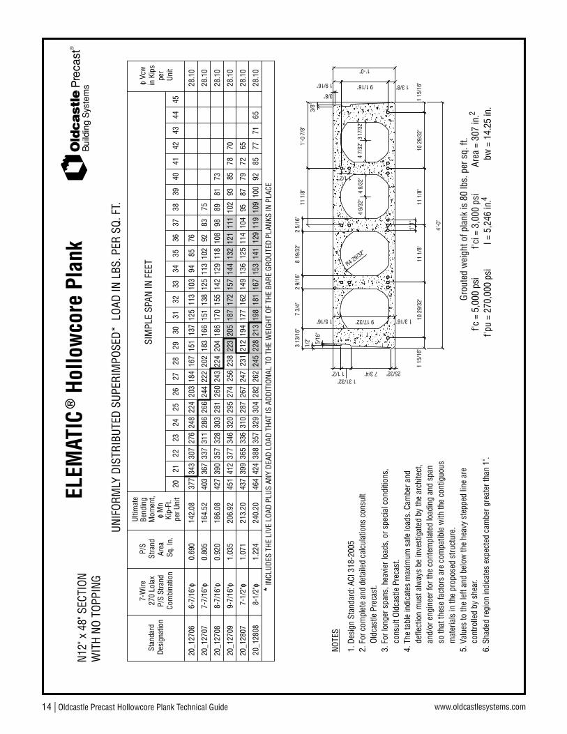
N12"
x 4
8" S
ECTI
ON
I = 5
,246
in.
f'ci =
3,0
00 p
siGr
oute
d w
eigh
t of p
lank
is 8
0 lb
s. p
er s
q. ft
.f'c
= 5
,000
psi
f'pu
= 27
0,00
0 ps
ibw
= 1
4.25
in.
Area
= 3
07 in
.4
2
248
INCL
UDES
THE
LIV
E LO
AD P
LUS
ANY
DEAD
LOA
D TH
AT IS
ADD
ITIO
NAL
TO T
HE W
EIGH
T OF
THE
BAR
E GR
OUTE
D PL
ANKS
IN P
LACE
Ultim
ate
Kip-
Ft.
Mom
ent,
142.
08
per U
nit
Bend
ing
*
270
Lola
xP/
S St
rand
Com
bina
tion
6-7/
16"o
7-W
ireSt
anda
rdDe
sign
atio
n
20_1
2706
0.69
0
Area
Sq. I
n.
Stra
ndP/
S
377
343
276
307
SIM
PLE
SPAN
IN F
EET
184
20
224
21
203
23
167
2224
151
2725
137
26
125
2829
3231
3033
34Un
itpe
r
28.1
0
in K
ips
o Vc
w
3635
286
320
7-7/
16"o
20_1
2707
20_1
2709
164.
52
206.
92
0.80
5
1.03
545
1
403
337
377
412
367
346
311
151
187
244
274
295
266
256
222
183
223
238
202
205
166
144
172
138
157
125
113
92 121
132
102
111
9310
285
28.1
0
28.1
0
3738
3940
4142
329
20_1
2808
240.
201.
224
424
464
388
357
198
282
304
262
228
245
213
153
181
167
129
141
119
100
109
9228
.10
7785
20_1
2708
8-7/
16"o
186.
080.
920
390
427
328
357
303
224
260
281
243
204
186
170
118
142
155
129
108
28.1
0
20_1
2807
213.
201.
071
399
437
336
365
310
9523
126
728
724
721
217
719
412
514
916
213
611
410
479
8728
.10
113
103
9889
72
9-7/
16"o
7-1/
2"o
8-1/
2"o
5. V
alue
s to
the
left
and
belo
w th
e he
avy
step
ped
line
are
cont
rolle
d by
she
ar.
mat
eria
ls in
the
prop
osed
stru
ctur
e.so
that
thes
e fa
ctor
s ar
e co
mpa
tible
with
the
cont
iguo
usan
d/or
eng
inee
r for
the
cont
empl
ated
load
ing
and
span
defle
ctio
n m
ust a
lway
s be
inve
stig
ated
by
the
arch
itect
,4.
The
tabl
e in
dica
tes
max
imum
saf
e lo
ads.
Cam
ber a
nd
3. F
or lo
nger
spa
ns, h
eavi
er lo
ads,
or s
peci
al c
ondi
tions
,
2. F
or c
ompl
ete
and
deta
iled
calc
ulat
ions
con
sult
cons
ult O
ldca
stle
Pre
cast
.
Oldc
astle
Pre
cast
.
NOTE
S
6. S
hade
d re
gion
indi
cate
s ex
pect
ed c
ambe
r gre
ater
than
1".
4344
45
9485
76
8375
8173
7870 65
7165
1. D
esig
n St
anda
rd: A
CI 3
18-2
005
3/8"
3/8"
1 3/8"9 1/16"1 9/16"
1 15
/16"
4'-0
"
R4 29/32"
11 1
/8"
8 19
/32"
25/32"
1/2"
7 3/4"
9 17/32"
3 13
/16"
1 3/16" 10 2
9/32
"1
15/1
6"1 5/16"
7 3/
4"
1 1/2"1 31/32"
5/16
"
2 9/
16"
11 1
/8"
1"1"
10 2
9/32
"
1 1/2"
4 9/
32"
11 1
/8"
4 9/
32"
2 5/
16"
3 17
/32"
4 7/
32"
1'-0"
1'-0
7/8
"

Oldcastle Precast Hollowcore Plank Technical Guide | 15www.oldcastlesystems.com
Bui
ldin
g S
yste
ms
ELEM
ATIC
® H
ollo
wco
re P
lank
o M
n
8-1/
2"o
UNIF
ORM
LY D
ISTR
IBUT
ED S
UPER
IMPO
SED*
LOA
D IN
LBS
. PER
SQ.
FT.
WIT
H 2"
TOP
PING
(350
0 PS
I)N1
2" x
48"
SEC
TION
INCL
UDES
THE
LIV
E LO
AD P
LUS
ANY
DEAD
LOA
D TH
AT IS
ADD
ITIO
NAL
TO T
HE W
EIGH
T OF
THE
BAR
E GR
OUTE
D PL
ANKS
& T
OPPI
NG
284
362
340
P/S
Stra
ndCo
mbi
natio
n
270
Lola
x
*
Desi
gnat
ion
Stan
dard
7-W
ireM
omen
t,Be
ndin
g
Area
Sq. I
n.
Stra
ndP/
S
Kip-
Ft.
per U
nit
Ultim
ate
20 519
487
444
21 395
472
444
23 395
371
317
22 353
431
404
2445
SIM
PLE
SPAN
IN F
EET
27 208
286
252
25 256
334
307
26 231
310
278
28 259
229
188
29 170
233
206
32 120
146
170
136
164
189
30 154
210
184
3133 12
9
104
153
34 90 114
137
40
95
36 87 108
35 100
122
3738 83
3941
4243
44
per
Unit
33.3
9
o Vc
win
Kip
s
Grou
ted
wei
ght o
f pla
nk &
2" t
oppi
ng is
80+
25 =
105
lbs.
per
sq.
ft.
f'c =
5,0
00 p
si
f'pu
= 27
0,00
0 ps
i
f'ci =
3,0
00 p
si
Ic =
8,3
93 in
.4
Area
= 3
07 in
.
bw =
14.
25 in
.2
290
271
484
515
567
532
431
404
471
441
396
371
316
337
365
343
312
293
131
153
270
245
249
226
221
199
186
162
205
180
169
146
93 112
138
118
124
105
70 9010
1
81
8061
6170
280.
00
248.
92
192.
96
217.
56
167.
28
281
500
241.
6455
041
845
638
432
735
430
214
125
923
421
217
319
215
610
112
711
478
89
33.3
9
33.3
9
33.3
9
33.3
9
33.3
9
6-7/
16"o
8-7/
16"o
7-7/
16"o
20_1
2706
T
20_1
2707
T
20_1
2708
T
0.69
0
0.92
0
0.80
5
20_1
2709
T9-
7/16
"o1.
035
7-1/
2"o
20_1
2807
T
20_1
2808
T
1.07
1
1.22
4
5. V
alue
s to
the
left
and
belo
w th
e he
avy
step
ped
line
are
cont
rolle
d by
she
ar.
mat
eria
ls in
the
prop
osed
stru
ctur
e.so
that
thes
e fa
ctor
s ar
e co
mpa
tible
with
the
cont
iguo
usan
d/or
eng
inee
r for
the
cont
empl
ated
load
ing
and
span
defle
ctio
n m
ust a
lway
s be
inve
stig
ated
by
the
arch
itect
,4.
The
tabl
e in
dica
tes
max
imum
saf
e lo
ads.
Cam
ber a
nd
3. F
or lo
nger
spa
ns, h
eavi
er lo
ads,
or s
peci
al c
ondi
tions
,
2. F
or c
ompl
ete
and
deta
iled
calc
ulat
ions
con
sult
cons
ult O
ldca
stle
Pre
cast
.
Oldc
astle
Pre
cast
.
NOTE
S
6. S
hade
d re
gion
indi
cate
s ex
pect
ed c
ambe
r gre
ater
than
1".
78
75
72
1. D
esig
n St
anda
rd: A
CI 3
18-2
005
3/8"
3/8"
1 3/8"9 1/16"1 9/16"
1 15
/16"
4'-0
"
R4 29/32"
11 1
/8"
8 19
/32"
25/32"
1/2"
7 3/4"
9 17/32"
3 13
/16"
1 3/16" 10 2
9/32
"1
15/1
6"1 5/16"
7 3/
4"
1 1/2"1 31/32"
5/16
"
2 9/
16"
11 1
/8"
1"1"
10 2
9/32
"
1 1/2"
4 9/
32"
11 1
/8"
4 9/
32"
2 5/
16"
3 17
/32"
4 7/
32"
1'-0"
1'-0
7/8
"
2"
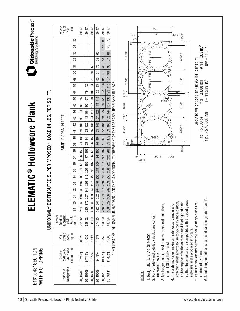
16 | Oldcastle Precast Hollowcore Plank Technical Guide www.oldcastlesystems.com
Bui
ldin
g S
yste
ms
ELEM
ATIC
® H
ollo
wco
re P
lank
o M
n
3/8"
3/8"
1 3/8"1'-1"1 5/8"
1 15
/16"
4'-0
"
R4 13/16"
11 1
/8"
8 31
/32"
25/32"
1/2"
11 3/4"
1'-0 19/32"
2 7/
8"
1 13/32"
10 2
9/32
"1
15/1
6"
1 31/32"
8 25
/32"
1 1/2"1 31/32"
5/16
"
2 5/
32"
11 1
/8"
1"1"
10 2
9/32
"
1 1/2"
4 17
/32"
11 1
/8"
4 17
/32"
2 5/
32"
4 3/
8"4
3/8"
1'-4"
1'-0
7/8
"
1 9/16"
UNIF
ORM
LY D
ISTR
IBUT
ED S
UPER
IMPO
SED*
LOA
D IN
LBS
. PER
SQ.
FT.
WIT
H NO
TOP
PING
E16"
x 4
8" S
ECTI
ON
I = 1
1,33
9 in
.f'c
i = 3
,000
psi
Grou
ted
wei
ght o
f pla
nk is
95
lbs.
per
sq.
ft.
f'c =
5,0
00 p
sif'p
u =
270,
000
psi
bw =
11.
3 in
.Ar
ea =
365
in.
4
2
216
INCL
UDES
THE
LIV
E LO
AD P
LUS
ANY
DEAD
LOA
D TH
AT IS
ADD
ITIO
NAL
TO T
HE W
EIGH
T OF
THE
BAR
E GR
OUTE
D PL
ANKS
IN P
LACE
Ultim
ate
Kip-
Ft.
Mom
ent,
261.
12
per U
nit
Bend
ing
*
270
Lola
xP/
S St
rand
Com
bina
tion
8-7/
16"o
7-W
ireSt
anda
rdDe
sign
atio
n
20_1
6708
0.92
0
Area
Sq. I
n.
Stra
ndP/
S
281
263
230
246
SIM
PLE
SPAN
IN F
EET
179
29
203
30
191
32
166
3133
153
3634
141
35
130
3738
4140
3942
43Un
itpe
r
30.6
7
in K
ips
o Vc
w
4544
226
248
9-7/
16"o
20_1
6709
20_1
6809
288.
52
374.
20
1.03
5
1.37
732
2
295
257
282
301
275
264
241
144
164
200
219
233
212
206
188
167
183
194
177
174
155
137
155
133
147
123
113
95 119
128
104
110
9510
288
30.6
7
30.6
7
4647
4849
5051
269
20_1
6811
437.
241.
683
327
350
306
287
179
238
253
225
200
212
189
152
169
160
137
144
130
115
123
107
30.6
793
100
20_1
6808
8-1/
2"o
341.
601.
224
288
308
252
269
237
186
209
222
197
175
166
156
115
134
145
124
107
30.6
7
20_1
6810
406.
001.
530
314
336
276
294
259
113
203
229
243
216
192
171
181
138
154
162
146
130
121
9810
530
.67
119
109
9991
91
9-1/
2"o
10-1
/2"o
11-1
/2"o
5. V
alue
s to
the
left
and
belo
w th
e he
avy
step
ped
line
are
cont
rolle
d by
she
ar.
mat
eria
ls in
the
prop
osed
stru
ctur
e.so
that
thes
e fa
ctor
s ar
e co
mpa
tible
with
the
cont
iguo
usan
d/or
eng
inee
r for
the
cont
empl
ated
load
ing
and
span
defle
ctio
n m
ust a
lway
s be
inve
stig
ated
by
the
arch
itect
,4.
The
tabl
e in
dica
tes
max
imum
saf
e lo
ads.
Cam
ber a
nd
3. F
or lo
nger
spa
ns, h
eavi
er lo
ads,
or s
peci
al c
ondi
tions
,
2. F
or c
ompl
ete
and
deta
iled
calc
ulat
ions
con
sult
cons
ult O
ldca
stle
Pre
cast
.
Oldc
astle
Pre
cast
.
NOTE
S
6. S
hade
d re
gion
indi
cate
s ex
pect
ed c
ambe
r gre
ater
than
1".
5253
5455
9991
8275 87
7279
8476
6370 81
7569
63
8478
7262
67
8781
7075
1. D
esig
n St
anda
rd: A
CI 3
18-2
005

Oldcastle Precast Hollowcore Plank Technical Guide | 17www.oldcastlesystems.com
Bui
ldin
g S
yste
ms
ELEM
ATIC
® H
ollo
wco
re P
lank
4'-0
"
1 15
/16"1 5/8" 1'-1" 1 3/8"
3/8"
8 31
/32"
11 1
/8"
R4 13/16"
8 25
/32"
1 31/32"
10 2
9/32
"
1 13/32"
2 7/
8"
1'-0 19/32"
11 3/4"
1/2"
1 15
/16"
25/32"1 31/32"
1 1/2"
5/16
"
2 5/
32"
11 1
/8"
4 17
/32"1 1/2"
11 1
/8"
2 5/
32" 4
17/3
2"
1 9/16"
1"1"
4 3/
8"4
3/8"
10 2
9/32
"
1'-0
7/8
"
1'-4"
2"
3/8"
UNIF
ORM
LY D
ISTR
IBUT
ED S
UPER
IMPO
SED*
LOA
D IN
LBS
. PER
SQ.
FT.
WIT
H 2"
TOP
PING
(350
0 PS
I)E1
6" x
48"
SEC
TION IN
CLUD
ES T
HE L
IVE
LOAD
PLU
S AN
Y DE
AD L
OAD
THAT
IS A
DDIT
IONA
L TO
THE
WEI
GHT
OF T
HE B
ARE
GROU
TED
PLAN
KS &
TOP
PING
318
P/S
Stra
ndCo
mbi
natio
n
270
Lola
x
*
Desi
gnat
ion
Stan
dard
7-W
ireM
omen
t,Be
ndin
g
Area
Sq. I
n.
Stra
ndP/
S
Kip-
Ft.
per U
nit
Ultim
ate
o M
n
45
SIM
PLE
SPAN
IN F
EET
256
295
275
240
29
224
32
173
191
30
209
3133
156
34
141
4036
35
127
3738
3941
4243
44
34.8
7
34.8
7
per
Unit
34.8
7
o Vc
win
Kip
s
Grou
ted
wei
ght o
f pla
nk &
2" t
oppi
ng is
95+
25 =
120
lbs.
per
sq.
ft.
f'c =
5,0
00 p
sif'p
u =
270,
000
psi
f'ci =
3,0
00 p
siIc
= 1
6,34
8 in
.4Ar
ea =
365
in.
bw =
11.
3 in
.2
279
252
367
334
289
319
342
310
298
269
146
179
261
235
244
229
221
206
202
176
215
193
190
161
107
140
166
132
152
119
85 117
128
95
107
8797
417.
60
323.
72
293.
52
4946
4748
5051
489.
7237
340
134
932
630
512
319
723
626
828
625
122
220
915
517
518
516
514
513
410
411
395
8734
.87
453.
9635
838
533
431
229
211
018
822
625
627
324
021
219
914
316
717
715
513
112
092
101
34.8
7
380.
4432
635
030
326
528
316
220
423
224
821
719
217
711
213
514
812
310
190
34.8
7
114
101
8-7/
16"o
20_1
6708
T0.
920
9-7/
16"o
20_1
6709
T
20-1
6809
T
1.03
5
1.37
7
20_1
6811
T1.
683
20_1
6808
T8-
1/2"
o1.
224
20_1
6810
T1.
530
9-1/
2"o
10-1
/2"o
11-1
/2"o
5. V
alue
s to
the
left
and
belo
w th
e he
avy
step
ped
line
are
cont
rolle
d by
she
ar.
mat
eria
ls in
the
prop
osed
stru
ctur
e.so
that
thes
e fa
ctor
s ar
e co
mpa
tible
with
the
cont
iguo
usan
d/or
eng
inee
r for
the
cont
empl
ated
load
ing
and
span
defle
ctio
n m
ust a
lway
s be
inve
stig
ated
by
the
arch
itect
,4.
The
tabl
e in
dica
tes
max
imum
saf
e lo
ads.
Cam
ber a
nd
3. F
or lo
nger
spa
ns, h
eavi
er lo
ads,
or s
peci
al c
ondi
tions
,
2. F
or c
ompl
ete
and
deta
iled
calc
ulat
ions
con
sult
cons
ult O
ldca
stle
Pre
cast
.
Oldc
astle
Pre
cast
.
NOTE
S
6. S
hade
d re
gion
indi
cate
s ex
pect
ed c
ambe
r gre
ater
than
1".
5253
5455
9080
70
75
8071
62 7861
69 8467
75
7279
64
1. D
esig
n St
anda
rd: A
CI 3
18-2
005
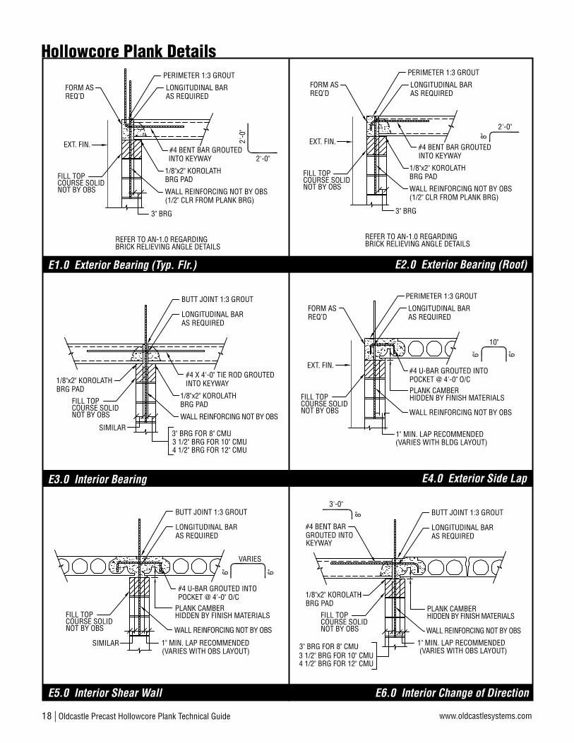
18 | Oldcastle Precast Hollowcore Plank Technical Guide www.oldcastlesystems.com
(VARIES WITH BLDG LAYOUT)1" MIN. LAP RECOMMENDED
PLANK CAMBERHIDDEN BY FINISH MATERIALS
POCKET @ 4'-0" O/C
10"
#4 U-BAR GROUTED INTO
6" 6"
COURSE SOLIDFILL TOP
NOT BY OBS
EXT. FIN.
PERIMETER 1:3 GROUT
LONGITUDINAL BARAS REQUIRED
WALL REINFORCING NOT BY OBS
FORM ASREQ’D
#4 U-BAR GROUTED INTOPOCKET @ 4'-0" O/C
1" MIN. LAP RECOMMENDEDSIMILAR(VARIES WITH OBS LAYOUT)
VARIES
6" 6"
WALL REINFORCING NOT BY OBSCOURSE SOLIDFILL TOP
NOT BY OBS
PLANK CAMBERHIDDEN BY FINISH MATERIALS
LONGITUDINAL BARAS REQUIRED
BUTT JOINT 1:3 GROUT
#4 BENT BAR
KEYWAY
3 1/2" BRG FOR 10" CMU4 1/2" BRG FOR 12" CMU
3" BRG FOR 8" CMU
GROUTED INTO
1" MIN. LAP RECOMMENDED(VARIES WITH OBS LAYOUT)
3'-0"
8"
1/8"x2" KOROLATHBRG PAD
COURSE SOLIDFILL TOP
NOT BY OBS WALL REINFORCING NOT BY OBS
PLANK CAMBERHIDDEN BY FINISH MATERIALS
LONGITUDINAL BARAS REQUIRED
BUTT JOINT 1:3 GROUT
#4 X 4'-0" TIE ROD GROUTEDINTO KEYWAY
LONGITUDINAL BARAS REQUIRED
1/8"x2" KOROLATHBRG PAD
3 1/2" BRG FOR 10" CMU4 1/2" BRG FOR 12" CMU
3" BRG FOR 8" CMUSIMILAR
BUTT JOINT 1:3 GROUT
1/8"x2" KOROLATHBRG PAD
WALL REINFORCING NOT BY OBSCOURSE SOLIDFILL TOP
NOT BY OBS
2'-0"
3" BRG
INTO KEYWAY#4 BENT BAR GROUTED
8"
EXT. FIN.
PERIMETER 1:3 GROUT
LONGITUDINAL BARAS REQUIRED
COURSE SOLIDFILL TOP
NOT BY OBS
1/8"x2" KOROLATH
WALL REINFORCING NOT BY OBS(1/2" CLR FROM PLANK BRG)
BRG PAD
FORM ASREQ’D
REFER TO AN-1.0 REGARDINGBRICK RELIEVING ANGLE DETAILS
COURSE SOLIDFILL TOP
NOT BY OBS
FORM AS
PERIMETER 1:3 GROUT
1/8"x2" KOROLATH
3" BRG
WALL REINFORCING NOT BY OBS(1/2" CLR FROM PLANK BRG)
BRG PAD
#4 BENT BAR GROUTEDINTO KEYWAY
LONGITUDINAL BARAS REQUIRED
2'-0
"
2'-0"
REQ’D
EXT. FIN.
REFER TO AN-1.0 REGARDINGBRICK RELIEVING ANGLE DETAILS
Hollowcore Plank Details
E1.0 Exterior Bearing (Typ. Flr.) E2.0 Exterior Bearing (Roof)
E3.0 Interior Bearing E4.0 Exterior Side Lap
E5.0 Interior Shear Wall E6.0 Interior Change of Direction

Oldcastle Precast Hollowcore Plank Technical Guide | 19www.oldcastlesystems.com
6'-0
" MAX
.
10'-0
" MAX
.4'-0
"
ADJ. PLANK
PC SOLID SLAB W/ INTEGRAL SIDE BALCONY
L/2 MAX.
L
PLAN VIEW
BRG
WAL
L
BRG
WAL
L
1/4:
12 P
ITCH
SEE U-BAR DETAILPER SECTION 9
NOT BY OBSCOURSE SOLIDFILL TOP
1'-4" MAX
POCKETS @ 4'-0" O/C#4 U-BAR GROUTED INTO
#4 X 1'-0" DOWELDRILL & GROUT AFTERPLANK ERECTION @ 8'-0" O.C.
1'-0"
6" 6"
ROOFING MATERIAL NOT SHOWN FOR CLARITY
PLANK CAMBERHIDDEN BY FINISH MATERIALS
T+2"
T
1/8"x2" KOROLATHBRG PAD
FILL TOP
NOT BY OBSCOURSE SOLID
CANTILEVER LENGTH VARIES
3" BRG
WELDED CONNECTIONDESIGNED BY OBS ENG.
PC SOLIDAT CONNECTIONS
PC SOLID BALCONY SLABWITH 1/4" IN 12" PITCH
DRIP EDGE
5'-0" MAX. FOR T = 4"6'-0" MAX. FOR T = 6"7'-0" MAX. FOR T = 8"
STEEL SHIM IF REQ’D
TEMP. SHORING IF REQ’D
STANDARD TWO EAR HEADER
ONE EAR HEADERTHIS END SUPPORTEDON CMU BRG WALL
PLANK THK HEADER ANGLE EAR PLATE
ELEMATIC 6" L 4"x4"x3/8" PLT 4"x1/2" X 1'-1"ELEMATIC 8" L 6"x4"x3/8" PLT 4"x1/2" X 1'-1"ELEMATIC 10" L 7"x4"x1/2" PLT 4"x5/8" X 1'-1"ELEMATIC 12" L 8"x4"x1/2" PLT 4"x3/4" X 1'-1"
(RECESS FOR ANGLE THK)
1/8"x2" KOROLATHBRG PAD4'-0" MAX. FOR 8" PLANK
CANTILEVER LENGTH VARIES
5'-0" MAX. FOR 10" PLANK6'-0" MAX. FOR 12" PLANK FILL TOP
NOT BY OBSCOURSE SOLID
#4 X 1'-0" DOWELDRILL & GROUT IN KEYWAYS@48" O/C AFTER PLANK ERECTION
BAY WINDOW WALLEXTERIOR FINISH TOBYPASS PLANK END
INSULATION BY OTHERS TOP REINFORCINGDESIGNED BY OBS ENG.
PLK
*CONTACT OBS ENG FOR 6" PLANK
3'-0
" TO
5'-0
" (NT
S)
GROUT SOLID CORE IF REQ’D.
PLAN VIEW
STEEL HEADER
DESIGN BY OBS ENG.
A
SECT A
HEADER ANGLE
1"
Hollowcore Plank Details
E7.0 Header Support at Large Opening E8.0 Plank Header Types
E9.0 Small Side Plank Roof Overhang E10.0 Cantilever Plank for Bay Windows
E11.0 Cantilever Solid Slab Balconies E12.0 Side Cantilever Balconies

20 | Oldcastle Precast Hollowcore Plank Technical Guide www.oldcastlesystems.com
#4 X 4'-0" TIE RODGROUTED INTO KEYWAY
LC
2" JT. FOR 1/2" THK ANGLES3" JT. FOR 3/4" THK ANGLES
BUTT JOINT 1:3 GROUT
4" MIN. ANGLE LEG
MAX CAMBER AT MIDSPANJUMPER PLATES AS REQ'D
LC
VARIES1'-0" MAX. @ 8'-0" O/C
SIDE WELD PLATES
3/16" 3"
3/16" 3"
#4 BENT BAR
KEYWAYGROUTED INTO
3'-0"
8" LC
1" PASS
1/2" MIN. LAP
BUTT JOINT 1:3 GROUT
PLANK CAMBERHIDDEN BY FINISH MATERIALS
(1) WELD PLATE@ 4'-0" O.C.
3/16" 3"
2 1/2" MIN. BRG
7" MINRECOMMENDED
#4 X 4'-0" TIE ROD GROUTED
LC
1"1"
INTO KEYWAY
IF RESTRAINT IS EXCESSIVE. WELDING ALTERNATINGNOTE: DO NOT WELD BOTH ENDS OF THE SAME PLANK
PLANKS WILL STILL PROVIDE LATERAL BEAM BRACING.
(1) WELD PLATE@ 4'-0" O.C.
3/16" 3"
LONGITUDINAL BARAS REQUIRED
BUTT JOINT 1:3 GROUT
LC
@ 8'-0" O/CSIDE WELD PLATES
MAX CAMBER AT MIDSPANJUMPER PLATES AS REQ'D
3/16" 3"
3/16" 3"
LC
1" PASS
IF RESTRAINT IS EXCESSIVE. WELDING ALTERNATINGNOTE: DO NOT WELD BOTH ENDS OF THE SAME PLANK
PLANKS WILL STILL PROVIDE LATERAL BEAM BRACING.
(1) WELD PLATE@ 4'-0" O.C.
3/16" 3"
Hollowcore Plank Details
E13.0 End Bearing on Steel E14.0 Interior Bearing on Steel
E15.0 Exterior Side Lap on Steel E16.0 Interior Side Lap on Steel
E17.0 Interior Change of Direction E18.0 Angle Support at Corridors
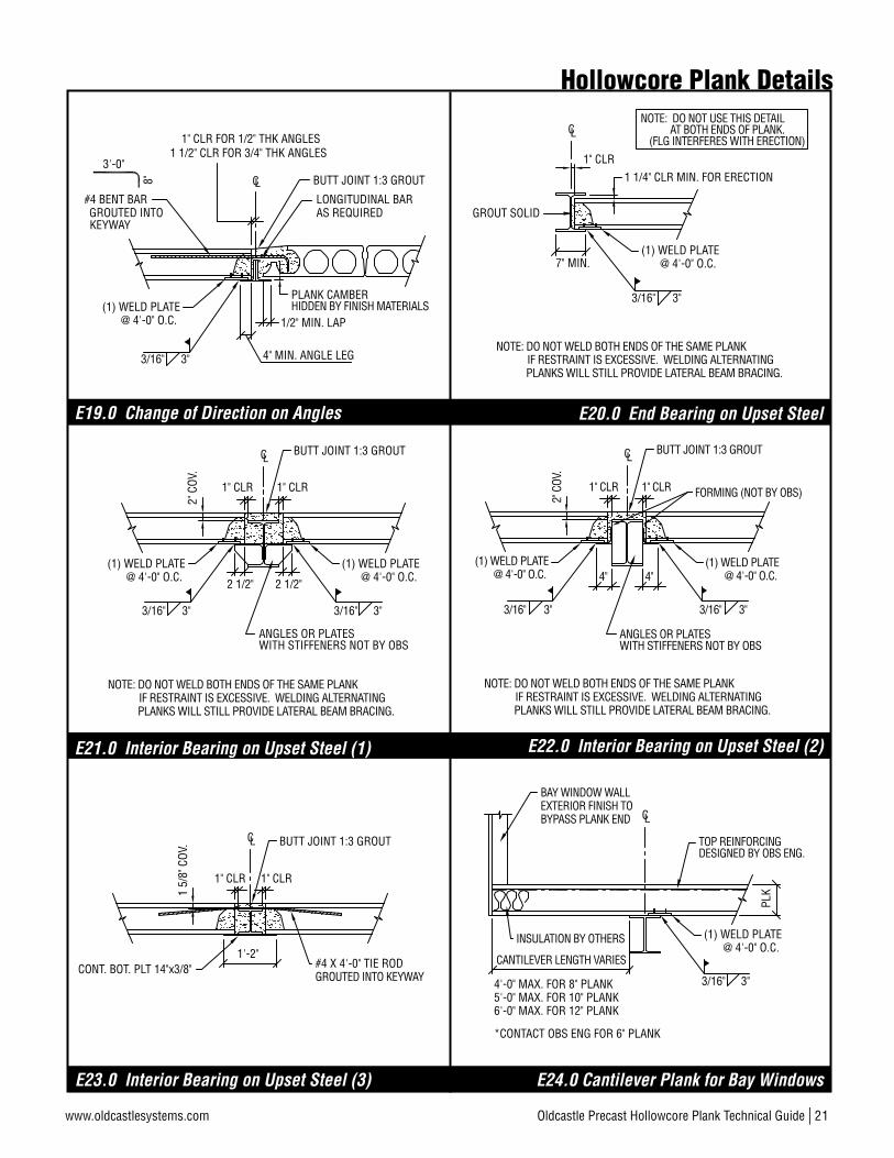
Oldcastle Precast Hollowcore Plank Technical Guide | 21www.oldcastlesystems.com
4'-0" MAX. FOR 8" PLANK
CANTILEVER LENGTH VARIES
5'-0" MAX. FOR 10" PLANK6'-0" MAX. FOR 12" PLANK
BAY WINDOW WALLEXTERIOR FINISH TOBYPASS PLANK END
INSULATION BY OTHERS
TOP REINFORCINGDESIGNED BY OBS ENG.
PLK
LC
*CONTACT OBS ENG FOR 6" PLANK
(1) WELD PLATE@ 4'-0" O.C.
3/16" 3"
BUTT JOINT 1:3 GROUT
#4 BENT BAR
KEYWAYGROUTED INTO
LONGITUDINAL BARAS REQUIRED
3'-0"8" LC
1" CLR FOR 1/2" THK ANGLES1 1/2" CLR FOR 3/4" THK ANGLES
1/2" MIN. LAP
4" MIN. ANGLE LEG
(1) WELD PLATE@ 4'-0" O.C.
3/16" 3"
PLANK CAMBERHIDDEN BY FINISH MATERIALS
IF RESTRAINT IS EXCESSIVE. WELDING ALTERNATINGNOTE: DO NOT WELD BOTH ENDS OF THE SAME PLANK
PLANKS WILL STILL PROVIDE LATERAL BEAM BRACING.
LC
1" CLR1" CLR
BUTT JOINT 1:3 GROUT
ANGLES OR PLATESWITH STIFFENERS NOT BY OBS
2" C
OV.
2 1/2"2 1/2"
(1) WELD PLATE@ 4'-0" O.C.
3/16" 3"
(1) WELD PLATE@ 4'-0" O.C.
3/16" 3"
IF RESTRAINT IS EXCESSIVE. WELDING ALTERNATINGNOTE: DO NOT WELD BOTH ENDS OF THE SAME PLANK
PLANKS WILL STILL PROVIDE LATERAL BEAM BRACING.
GROUT SOLID
LC
7" MIN.
1" CLR1 1/4" CLR MIN. FOR ERECTION
AT BOTH ENDS OF PLANK.NOTE: DO NOT USE THIS DETAIL
(FLG INTERFERES WITH ERECTION)
(1) WELD PLATE@ 4'-0" O.C.
3/16" 3"
1" CLR1" CLR
LC BUTT JOINT 1:3 GROUT
1 5/
8" C
OV.
1'-2"CONT. BOT. PLT 14"x3/8" #4 X 4'-0" TIE ROD
GROUTED INTO KEYWAY
IF RESTRAINT IS EXCESSIVE. WELDING ALTERNATINGNOTE: DO NOT WELD BOTH ENDS OF THE SAME PLANK
PLANKS WILL STILL PROVIDE LATERAL BEAM BRACING.
1" CLR
4"
1" CLR
4"
LCBUTT JOINT 1:3 GROUT
2" C
OV.
ANGLES OR PLATESWITH STIFFENERS NOT BY OBS
(1) WELD PLATE@ 4'-0" O.C.
3/16" 3"
(1) WELD PLATE@ 4'-0" O.C.
3/16" 3"
FORMING (NOT BY OBS)
Hollowcore Plank Details
E19.0 Change of Direction on Angles E20.0 End Bearing on Upset Steel
E21.0 Interior Bearing on Upset Steel (1) E22.0 Interior Bearing on Upset Steel (2)
E23.0 Interior Bearing on Upset Steel (3) E24.0 Cantilever Plank for Bay Windows

22 | Oldcastle Precast Hollowcore Plank Technical Guide www.oldcastlesystems.com
6"
BUTT JOINT 1:3 GROUT
#4 X 4'-0" TIE ROD GROUTEDINTO KEYWAY
1"
2 1/2" BRG2 1/2" BRG
TOP FINGER SLOTSIN PLANKS FORGROUT ACCESS
(1) WELD PLATE@ 4'-0" O.C.
(1) WELD PLATE@ 4'-0" O.C.
3/16" 3"3/16" 3"
8" MIN.GROUT
8" MIN.GROUT
DB8 GIRDER#4 X 2'-0"@ 2'-0" O.C.
FACTORY SLOTSFOR GROUT ACCESS4"AT EACH CORE
4000 PSI GROUTCONT. ALONG DB8
3" BRG(2" MIN.)
(1) WELD PLATE@ 4'-0" O.C.
8"
(1) WELD PLATE@ 4'-0" O.C.
BUTT JOINT 1:3 GROUT
#4 X 4'-0" TIE ROD GROUTEDINTO KEYWAY
2"
3" BRG 3" BRG
3/16" 3"3/16" 3"
(LOAD BEARING)CFS METAL WALL
6"
FORM AS REQ’D
1 1/2"
(1) WELD PLATE@ 4'-0" O.C.
BUTT JOINT 1:3 GROUT
3 1/2"BRG
1"
3/16" 3"
SMALL CORE
FIELD INSTALLED ANCHOR NOT BY OBS
BENT PLATE OR ANGLE NOT BY OBS
(NONLOAD BEARING)CFS METAL WALL
4" OR 6" CFS METAL WALL
SMALL CORE
4" OR 6" CFS METAL WALL
(NONLOAD BEARING)CFS METAL WALL
FIELD INSTALLED ANCHOR NOT BY OBS
FIELD INSTALLED ANCHOR NOT BY OBS
SHIMMING OF METAL STUDS REQ’DTO ADJUST FOR PLANK CAMBER
Hollowcore Plank Details
E29.0 Interior Bearing on 6" Metal Wall E30.0 Typ. Girder-Slab System
E25.0 Exterior Bearing on Metal Stud E26.0 Exterior Bypass Side on Metal Stud
E27.0 Exterior Side Lap on Metal Stud E28.0 Interior Bearing on 8" Metal Wall
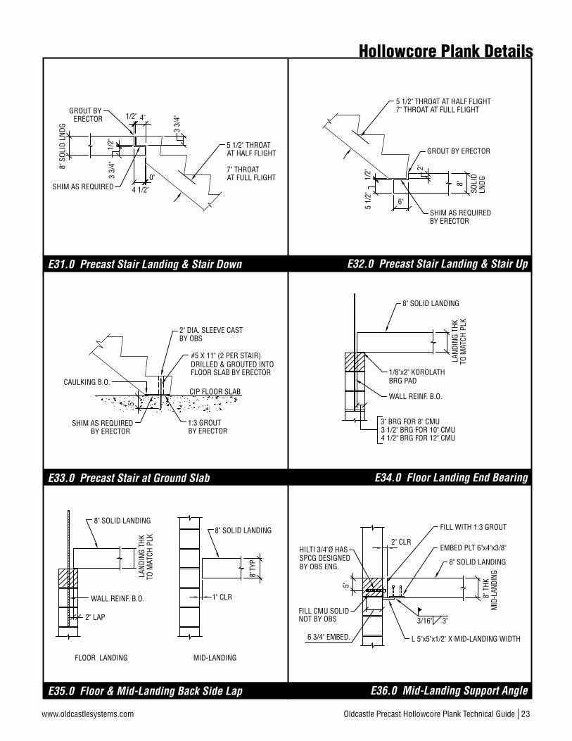
Oldcastle Precast Hollowcore Plank Technical Guide | 23www.oldcastlesystems.com
8" T
HKM
ID-L
ANDI
NG
2" CLR
L 5"x5"x1/2" X MID-LANDING WIDTH
EMBED PLT 6"x4"x3/8"
5"
NOT BY OBSFILL CMU SOLID
FILL WITH 1:3 GROUT
HILTI 3/4"Ø HAS
6 3/4" EMBED.
SPCG DESIGNEDBY OBS ENG. 8" SOLID LANDING
3/16" 3"
CAULKING B.O.
SHIM AS REQUIREDBY ERECTOR
#5 X 11" (2 PER STAIR)DRILLED & GROUTED INTOFLOOR SLAB BY ERECTOR
CIP FLOOR SLAB
1:3 GROUTBY ERECTOR
5"
2" DIA. SLEEVE CASTBY OBS
WALL REINF. B.O.
2" LAP
LAND
ING
THK
TO M
ATCH
PLK
8" SOLID LANDING
FLOOR LANDING
1" CLR
8" TY
P
8" SOLID LANDING
MID-LANDING
5 1/
2"1/
2"
GROUT BY ERECTOR
SHIM AS REQUIREDBY ERECTOR
8"
2"
5 1/2" THROAT AT HALF FLIGHT7" THROAT AT FULL FLIGHT
6"
SOLI
DLN
DG
1/8"x2" KOROLATHBRG PAD
WALL REINF. B.O.
3 1/2" BRG FOR 10" CMU4 1/2" BRG FOR 12" CMU
3" BRG FOR 8" CMU
LAND
ING
THK
TO M
ATCH
PLK
8" SOLID LANDING
5 1/2" THROATAT HALF FLIGHT
7" THROATAT FULL FLIGHT
GROUT BYERECTOR
8" S
OLID
LND
G
SHIM AS REQUIRED
1/2" 4"
3 3/
4"
4 1/2"
0"
1/2"
3 3/
4"
Hollowcore Plank Details
E31.0 Precast Stair Landing & Stair Down E32.0 Precast Stair Landing & Stair Up
E35.0 Floor & Mid-Landing Back Side Lap E36.0 Mid-Landing Support Angle
E33.0 Precast Stair at Ground Slab E34.0 Floor Landing End Bearing

Oldcastle Precast Hollowcore Plank Technical Guide | 23www.oldcastlesystems.com
LC
CANT. AS REQ’D
(1) WELD PLATE@ 4'-0" O.C.
3/16" 3"
DAP AS REQ’D
DAP
AS R
EQ’D
SOLID END
ELEVATOR SHAFT
ELEVATOR SHAFT
PERIMETER 1:3 GROUT
LONGITUDINAL BARAS REQUIRED
COURSE SOLIDFILL TOP
NOT BY OBSWALL REINFORCING NOT BY OBS
FORM ASREQ’D
2" O
RAS
REQ
’D
SHELF ANGLE(NOT BY OBS)
ELEVATOR SHAFT
PLANK CAMBERHIDDEN BY FINISH MATERIALS
POCKET @ 4'-0" O/C
12"
#4 U-BAR GROUTED INTO
6"
(VARIES WITH BLDG LAYOUT)1" MIN. LAP RECOMMENDED
6"
LC
DAP AS REQ’DDA
PAS
REQ
’D
SMALL CORE
ELEVATOR SHAFT
ELEVATOR SHAFT
CANT. AS REQ’D
MAX CAMBER AT MIDSPANJUMPER PLATES AS REQ’D
3/16" 3"
3/16" 3"
@ 8'-0" O/CSIDE WELD PLATES
2'-0"
3" BRG
INTO KEYWAY#4 BENT BAR GROUTED
8"
PERIMETER 1:3 GROUT
LONGITUDINAL BARAS REQUIRED
COURSE SOLIDFILL TOP
NOT BY OBS
1/8"x2" KOROLATH
WALL REINFORCING NOT BY OBS(1/2" CLR FROM PLANK BRG)
BRG PAD
FORM ASREQ’D
2" O
RAS
REQ
’D
SHELF ANGLE(NOT BY OBS)
ELEVATOR SHAFT
FLARE TOPOF CIP WALL
FORM AS
PERIMETER 1:3 GROUT
1/8"x2" KOROLATH
3" BRG
WALL REINFORCING NOT BY OBS(1/2" CLR FROM PLANK BRG)
BRG PAD
#4 BENT BAR GROUTEDINTO KEYWAY
LONGITUDINAL BARAS REQUIRED
2'-0
"
2'-0"
REQ’D
6"
(LOAD BEARING)CFS METAL WALL
6"
(1) BOTTOM WELD PLATE@ 4'-0" O.C. BY OBS
TOP PLATE 6"x3/8"x1'-0"CAST-IN PLANK
VARIES
L 8"x4"x1/2" X0'-8"SET BY ELEV. INSTALLER 1/4"
ELEVATORGUIDE RAIL
3/16" 3"
Hollowcore Plank Details
E37.0 Elevator Door Support Detail (1) E38.0 Elevator Door Support Detail (2)
E39.0 Elevator Door Support Detail (3) E40.0 Elevator Door Support Detail (4)
E41.0 Elevator Stud & Plank at Elevator Wall E42.0 Exterior Bearing on 6" ICF Wall
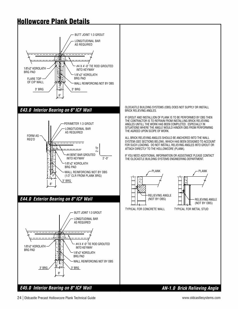
24 | Oldcastle Precast Hollowcore Plank Technical Guide www.oldcastlesystems.com
PLANK
OLDCASTLE BUILDING SYSTEMS (OBS) DOES NOT SUPPLY OR INSTALL BRICK RELIEVING ANGLES.
IF GROUT AND INSTALLION OF PLANK IS TO BE PERFORMED BY OBS THEN THE CONTRACTOR IS TO REFRAIN FROM INSTALLING BRICK RELIEVING ANGLES UNTILL THE WORK HAS BEEN COMPLETED. ESPECIALLY IN SITUATIONS WHERE THE ANGLE WOULD HINDER OBS FROM PERFORMING THE AGREED UPON SCOPE OF WORK.
ALL BRICK RELIEVING ANGLES SHOULD BE ANCHORED INTO THE WALL SYSTEM (SEE SECTIONS BELOW), WHICH HAS BEEN DESIGNED TO ACCOUNT FOR SUCH LOADING. DO NOT INSTALL RELIEVING ANGLES INTO GROUT OR ATTACH DIRECTLY TO THE HOLLOWCORE (PLANK).
IF YOU NEED ADDITIONAL INFORMATION OR ASSISTANCE PLEASE CONTACT THE OLDCASTLE BUILDING SYSTEMS ENGINEERING DEPARTMENT.
RELIEVING ANGLE(NOT BY OBS)
TYPICAL FOR CONCRETE WALL
PLANK
RELIEVING ANGLE(NOT BY OBS)
TYPICAL FOR METAL STUD
PERIMETER 1:3 GROUT
1/8"x2" KOROLATH
3" BRG
WALL REINFORCING NOT BY OBS(1/2" CLR FROM PLANK BRG)
BRG PAD
#4 BENT BAR GROUTEDINTO KEYWAY
LONGITUDINAL BARAS REQUIRED
2'-0
"
2'-0"
FORM ASREQ’D
8"
#4 X 4'-0" TIE ROD GROUTEDINTO KEYWAY
LONGITUDINAL BARAS REQUIRED
1/8"x2" KOROLATHBRG PAD
BUTT JOINT 1:3 GROUT
1/8"x2" KOROLATHBRG PAD
WALL REINFORCING NOT BY OBS
8"
3" BRG 3" BRG
#4 X 4'-0" TIE ROD GROUTEDINTO KEYWAY
LONGITUDINAL BARAS REQUIRED
1/8"x2" KOROLATHBRG PAD
BUTT JOINT 1:3 GROUT
1/8"x2" KOROLATHBRG PAD
WALL REINFORCING NOT BY OBS
6"
3" BRG3" BRG
FLARE TOPOF CIP WALL
Hollowcore Plank Details
E45.0 Interior Bearing on 8" ICF Wall
E44.0 Exterior Bearing on 8" ICF Wall
E43.0 Interior Bearing on 6" ICF Wall
AN-1.0 Brick Relieving Angle

Delivering Reliability
Oldcastle Precast Hollowcore Plank Technical Guide | 25www.oldcastlesystems.com

Oldcastle Precast Building Systems123 County Route 101 Selkirk, NY 12158800-523-3747
Oldcastle Precast Building Systems1401 Trimble Road Edgewood, MD 21040 Phone: 800-523-9144©2010 Oldcastle Precast
oldcastlesystems.com