guidance and submittal requirements for rapid … rapid infiltration basin wastewater treatment...
TRANSCRIPT
Guidance and Submittal Requirements for Rapid Infiltration Basin Wastewater
Treatment Systems
March 2005
Wq-wwtp5-64

Table of Contents
Page Table of Contents
i.
List of Figures and Tables
ii.
Purpose and Scope
1
Acknowledgments
1
I. Introduction 3 II. The Permitting Process. 4 III. Nitrogen Analysis and Considerations 4 IV. Preliminary RIB Design 6 V. Requirements for Site, Soils and Hydrogeologic Site Evaluation 8 VI. Determining Hydraulic Loading Rates 8 VII. Ground Water Mounding 10 VIII. Operational Criteria 10 IX. Engineering Design Report Submittal Requirements 12 X. Example Problem 12 XI. Summary and Conclusions 15 References 15 Appendix I (The Permitting Process) 17 Appendix II (Preliminary Site Suitability Evaluation) 19 Appendix III (Site Soils Evaluation) 23 Appendix IV (Hydrogeologic Report Requirements) 29 Appendix V (Limited Hydrogeologic Report Requirements) 33 Appendix VI (Engineering Report Requirements 35
List of Figures and Tables
Figure Number Page 1 Photograph of a Rapid Infiltration Basin System 4 2 Simplified RIB Permitting Process Flow Chart 4 Table Number 1 Suggested Loading and Resting Cycles 11 2 Phosphorous Impact Evaluation 26
iii

Purpose and Scope of this Document The purpose of this guidance document is to assist the Minnesota Pollution Control Agency (MPCA) and consulting technical staff (engineers, soil scientists, and geologists) in the design, permitting and operation of Rapid Infiltration Basin (RIB) wastewater dispersal systems (systems). This document presents discussions on the various technical requirements, and provides an overview of what is required to obtain an MPCA permit for an RIB system. Acknowledgments This guidance was written by Neal Wilson, Minnesota Pollution Control Agency Senior Hydrogeologist. The author would like to acknowledge the assistance of the following individuals in the preparation of this document: Stephanie Handeland, EuDale Mathiason, Brad Nordberg, Sally Patrick, Gene Soderbeck, Steve Stark, and Mark Wespetal.
1

Rapid Infiltration Basins I. Introduction What are Rapid infiltration Basins? Rapid Infiltration Basins (RIBs) are permeable earthen basins, designed and operated to treat and disperse municipal wastewater. RIBs are typically operated in conjunction with either a primary wastewater pond, or a primary and secondary wastewater pond system. How do they operate? A RIB system is managed by repetitive cycles of flooding, infiltration and drying. Rapid infiltration of wastewater is based on a relatively high rate of wastewater infiltration into the soil followed by rapid percolation, either vertically or laterally away. The best soils for rapid infiltration are relatively coarse textured, with moderate to rapid permeabilities (1). Particulates, BOD, trace metals and suspended solids are removed at least in part at or near the soil surface. Pathogen removal by RIB systems may be as high as 99.99%, with less attenuation occurring in coarser sands and gravel. Limited studies indicate that some degree of treatment may be afforded to volatile organic compounds by RIBs, by volatilization, sorption and degradation. Nitrification-denitrification is the primary nitrogen removal process. Total nitrogen removal efficiencies for RIB systems are approximately 50% (2), and more nitrogen may be removed by using special management practices. Air temperatures between 86°F-95°F are the optimal temperatures for nitrogen removal with the microbiologically mediated processes greatly slowing around 55°F, and stopping at or near freezing temperatures. Aerobic bacteria deplete soil oxygen during flooding periods, so resting/re-aerating the system is required for the system to properly function. A RIB drying cycle is typically five to ten times longer than the wetting cycle and in Minnesota RIB systems are usually not operated in the winter (120-150 days). These criteria need to be considered when proposing RIB hydraulic loading rates.
3

Figure 1: Rapid Infiltration Basins. II. The Permitting Process The following flow chart describes the typical sequence for obtaining an MPCA State Disposal System (SDS) Permit for a RIB. More detailed information on the permitting process is included in Appendix A.
Figure 2: Simplified RIB Permitting Process
Meet and discuss proposed project with MPCA staff
Submit to the MPCA a
Preliminary Proposal/Facilities
Plan
Submit to the MPCA Site
(Engineer, Permit writer, Hydrogeologist
Evaluation, Soils,Hydrogeologic
Workplans
Submit to and MPCA approval of
Site Evaluation, Soils and
Hyfdrogeologic Reports
MPCA review, Submit to the MPCA Plans MPCA review of Plans and
Specifications and permitting documents
approval of Preliminary
Proposal/Facilities Plan
and Specifications and a complete permit application with supporting documents
(see Appendix 1)
Facility constructed, brought into operations
Conduct basin-by-basin flooding tests
1 year Certification Report, and Final O&M Plan
approved by MPCA
MPCA Permit issued
Permit flow limits modified
as needed
4

III. Nitrogen Management Options Although there are several constituents of concern in wastewater one of the main constituents of concern that influences RIB system design is nitrate-nitrogen. In terms of nitrogen treatment and system design there are two options for obtaining an MPCA SDS Permit as described below. Irrespective of which track is selected at least a preliminary phosphorous setback evaluation will be required (see bottom of Appendix II). Option One If the effluent going to the RIBs (verified by on-going effluent monitoring) contains a maximum of 10 mg/L total nitrogen and there is adequate (a minimum of 100’) separation between the RIBs and the property line/and or the nearest receptor (surface water or potable water supply well) then only a limited hydrogeologic investigation, and no ground-water monitoring will be required. The requirements for a limited hydrogeologic investigation are included in Appendix V. Option Two If the conditions described in Option One above cannot be met then a complete hydrogeologic investigation and ground-water monitoring will be required. If the hydrogeologic evaluation demonstrates little potential for ground water impacts (e.g., the RIBs are in a ground-water discharge zone, no proximal water supply wells etc.) then a limit of 10 mg/L for nitrate-N will be assigned to down-gradient monitoring wells. If the hydrogeologic evaluation determines that the ground water has the potential for being impacted by the RIBs then a limit of 5 mg/L will be assigned to down-gradient monitoring wells. To reflect ambient conditions where existing ground water nitrate nitrogen concentrations are already elevated nitrate-N limits will be set at the mean of a minimum of three up-gradient ground water samples. In order to set limits an up-gradient well will have to have been sampled at least three times prior to public noticing the permit. Due to discharge flow dynamics more monitoring wells will usually be required the further the monitoring wells are placed from the RIBs. Normally RIBs should be located as far hydraulically up-gradient from the property line as possible. Any amount of land may be used as a treatment zone between the RIBs and the property line, but this land must not be used in any manner other than as an undeveloped treatment zone. Several nitrogen reduction methods may be employed at the same site to reduce ground water impacts from RIBs. Nitrogen reduction methods include: (1) initially locating the system where natural soil and/or ground water conditions promote
denitrification (anoxic and reducing conditions with some dissolved organic carbon); (2) locating the RIB system near a downgradient wetland, river or stream that captures, and
has the ability to further attenuate the discharge plume; (3) the RIBs being located as far up-gradient as possible, with the downgradient property maintained as green space;
5

(4) the RIBs designed as long as practical and perpendicular to the ground water contour; (5) (clean) stormwater infiltration downgradient of an RIB; (6) for suitable soils and shallower ground water using hybrid poplar trees to evapotranspirate
the discharge; (7) installation of downgradient recovery wells for non-potable (E.G. irrigation) use; (8) selecting loading and resting cycles that promote denitrification; and (9) control of downgradient land to the ground water discharge point which prohibits the installation and use water supply wells. IV. Preliminary RIB Design Suitable Locations A RIB system located on a relatively level site with deep, uniform, unsaturated moderately permeable soils, a deep water table, and is adjacent to a ground water discharge area should increase the performance of the system and reduce associated environmental impacts. Areas with steep slopes, shallow water tables, are adjacent to wetlands, or are in soils that are too coarse or too fine may make siting RIBs more difficult, or may reduce the performance of the RIB system. Unsuitable Locations Systems that are within wellhead protection areas, are proposed to be located in areas with shallow bedrock, are above sole-source aquifers, are located on a flood plain, or are in karst areas are most likely not suitable locations for RIB systems. Number of RIBs The minimum number of RIBs in a system is 3, but the number of basins can vary from 3-17 depending on whether continuous wastewater discharge is required. Individual basin size can range from 0.5-5 acres for small to medium-sized systems, to 5-20 acres for larger systems. The EPA has provided guidance on the number of basins needed, based on the projected number and duration of loading and resting cycles (3). Dimensions To maximize land use basins should adjoin, and be square or rectangular in shape. Long, narrow basins with their length perpendicular to ground water flow direction may reduce ground water mounding. The potential that basins will cause unacceptable mounding in adjacent basins needs to be evaluated during system design. Dikes Each basin should be constructed at least 12 inches deeper than the maximum design wastewater depth (4). Dikes need to be compacted to prevent seepage through them, and should be sloped so storm water runoff is routed away from the site. Extra freeboard is not recommended for routine wastewater containment (5). Dikes must be protected from erosion both during and after construction to keep fines from washing in and reducing basin infiltration.
6

Solutions for Less Favorable Soil Conditions Whenever possible basins should not be constructed on backfilled materials, and soil compaction during construction must be minimized. At sites where the infiltration rate is slow (finer, structureless soils) then more and larger basins with lower loading rates may be required. At sites with coarser soils, the soils may not provide uniform basin loading, or the soil based treatment (aerobic/anaerobic conditions) necessary to protect ground water. In Section 4.7.3. on page 48 of the United States Environmental Protection Agency (EPA) document Process Design Manual, Supplement on Rapid Infiltration and Overland Flow it states “In all cases, uniform wastewater application over the entire basin surface is necessary”. In more coarse soils to ensure uniform distribution “The distribution system might range from a network of pipes and troughs to sprinklers in the extreme case”. At RIB sites where the infiltration rate is too fast several options may be considered including the following:
• Having smaller basins and multiple inlets; • Carefully removing and stockpiling approximately 12” of the basin soil and then blending
finer textured soils (silt, 5%-10%) into the stockpiled soil, and then placing this reworked soil on top of a Geotextile material laid out in the basins;
• Placing a Geotextile material that sufficiently slows down infiltration directly on top of the RIBs (possibly using sandbags as anchors), and then placing 12” of clean sand on top of the reduced hydraulic conductivity Geotextile material;
• Installing a (very) level matrix of troughs made of concrete or pipe cut lengthwise that is installed and kept level so uniform distribution within the RIBs is maintained. A part of the Operations and Maintenance (O&M) Plan will require that the operator must routinely observe drainage, and re-level the drainage channels as necessary;
• Installing a matrix of pressure-distributed distribution lines (i.e. drain tile) with the orifices sized and positioned optimally (sideways or upright) so as to ensure uniform loading and reduced basin scouring;
• Spraying into the basins using a fixed set (overhead or vertical uprights) sprinkler system; or
• Finding a more suitable site, or selecting an alternative treatment technology. It should be noted that these are only some examples of possible solutions that may or may not work at a particular site. Other solutions may be possible, and calculations and bench and/or field testing of the selected design should be considered to ensure system viability, uniform distribution of the effluent, and optimally so that the predicted dosing periods would be long enough to induce anaerobic conditions for at least some portion of the load/rest cycle. V. Requirements for Site Suitability, Soils, and Hydrogeologic Site
Investigation Irrespective of which of the two nitrogen management options that are selected the permittee must undertake a Site Suitability Investigation, a Soils Investigation, and some form of a Hydrogeologic Investigation. The scope of the Hydrogeologic Investigation will depend on which of the two nitrogen management options is selected. The purpose of these investigations
7

is to characterize the area where the system is proposed to be installed, and to characterize the site soils for design purposes. Soils are critical for the treatment process. The person who prepares the soils report must certify by signature that they have expertise in Soil Science (defined by education and experience, especially soil morphology). They should have also have taken the Onsite Sewage Treatment Workshop Soils class or equivalent. Under some circumstances the person who designates where the soil pits are to be located may differ from the individual who actually logs the soil pits. If this occurs, then it must be noted in the Soils Report. When designing the system a minimum of three feet of soil must exist between the bottom of the RIBs and the actual ground water mound height (including the capillary fringe). For systems where mounding may be an issue (based on the mounding analyses) piezometers must be installed, and on-going measurements must be made in the piezometers to ensure that at minimum three feet of separation is maintained during operation. Appendices II, III and IV respectively provide more detailed discussions on what is required for the Site, Soils, and Hydrogeologic Investigations. VI. Determining Hydraulic Loading Rates The sequence for determining annual and individual hydraulic loading rates for RIB systems is as follows: 1. adequately characterize the site soils; 2. estimate annual and daily loading rates; and 3. verify the estimations with empirically-derived (actual) basin-by-basin flooding tests after the
basins are constructed. Hydraulic loading rates are estimated primarily on soil texture, consistence and structure of the most hydraulically limiting soil horizon above the seasonal high water table. A combination of these three soil properties will determine the most limiting soil horizon, and infiltration rates below the system. Laboratory sieve and permeability measurements, and/or preferably in-situ measurements using a double ring infiltrometer or equivalent method (6) of the most transmissive (i.e. quantity) and the most hydraulically limiting (MHL) horizons especially on less favorable sites should be undertaken for estimating hydraulic loading rates (see example on page 12, section IX). When working with RIBs the terms vertical hydraulic conductivity (K ), horizontal hydraulic conductivity (K ) and saturated hydraulic conductivity (K ) are used. Vertical hydraulic conductivity is used to estimate the rate of flow of water into and through the soil, in other words a “soil acceptance rate”. Horizontal hydraulic conductivity is used for mounding analysis. Mounding occurs when infiltrated wastewater (which is moving in a vertical direction) encounters the water table and cannot flow “away” from the application site fast enough.
v
h sat
The direction of this saturated flow or subsurface drainage has to be in a lateral direction “away” from the application site. Therefore some combination of K and K are used for mounding analysis. The further from the center of the mound, the more the ground water is controlled by
v h
8
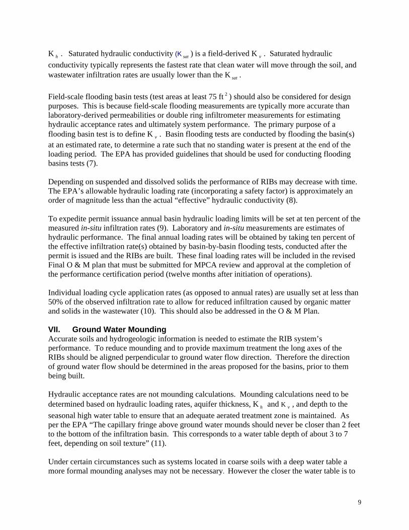
K . Saturated hydraulic conductivity (K ) is a field-derived K . Saturated hydraulic conductivity typically represents the fastest rate that clean water will move through the soil, and wastewater infiltration rates are usually lower than the K .
h sat v
sat
Field-scale flooding basin tests (test areas at least 75 ft ) should also be considered for design purposes. This is because field-scale flooding measurements are typically more accurate than laboratory-derived permeabilities or double ring infiltrometer measurements for estimating hydraulic acceptance rates and ultimately system performance. The primary purpose of a flooding basin test is to define K . Basin flooding tests are conducted by flooding the basin(s) at an estimated rate, to determine a rate such that no standing water is present at the end of the loading period. The EPA has provided guidelines that should be used for conducting flooding basins tests (7).
2
v
Depending on suspended and dissolved solids the performance of RIBs may decrease with time. The EPA’s allowable hydraulic loading rate (incorporating a safety factor) is approximately an order of magnitude less than the actual “effective” hydraulic conductivity (8). To expedite permit issuance annual basin hydraulic loading limits will be set at ten percent of the measured in-situ infiltration rates (9). Laboratory and in-situ measurements are estimates of hydraulic performance. The final annual loading rates will be obtained by taking ten percent of the effective infiltration rate(s) obtained by basin-by-basin flooding tests, conducted after the permit is issued and the RIBs are built. These final loading rates will be included in the revised Final O & M plan that must be submitted for MPCA review and approval at the completion of the performance certification period (twelve months after initiation of operations). Individual loading cycle application rates (as opposed to annual rates) are usually set at less than 50% of the observed infiltration rate to allow for reduced infiltration caused by organic matter and solids in the wastewater (10). This should also be addressed in the O & M Plan. VII. Ground Water Mounding Accurate soils and hydrogeologic information is needed to estimate the RIB system’s performance. To reduce mounding and to provide maximum treatment the long axes of the RIBs should be aligned perpendicular to ground water flow direction. Therefore the direction of ground water flow should be determined in the areas proposed for the basins, prior to them being built. Hydraulic acceptance rates are not mounding calculations. Mounding calculations need to be determined based on hydraulic loading rates, aquifer thickness, K and K , and depth to the seasonal high water table to ensure that an adequate aerated treatment zone is maintained. As per the EPA “The capillary fringe above ground water mounds should never be closer than 2 feet to the bottom of the infiltration basin. This corresponds to a water table depth of about 3 to 7 feet, depending on soil texture” (11).
h v
Under certain circumstances such as systems located in coarse soils with a deep water table a more formal mounding analyses may not be necessary. However the closer the water table is to
9

the base of the RIBs, the more variable the soils, the higher the proposed loading rates and the lower the K , the more important mounding calculations become and corresponding, the more conservative the assumptions used should be when making the calculations. The EPA estimation (12) and the Finnemore and Hantzsche method (13) are acceptable methods for estimating mounding (see bottom of Appendix II).
h
Mounding calculations are estimates. Depending on the potential for mounding estimated from the mounding analyses piezometers will need to be installed between or immediately adjacent to the RIBs. An enforceable part of the MPCA permit will state that even with mounding, the ground water surface as measured in the piezometers will need to be kept 3 feet or lower than the bottom of the RIBs. Therefore the surveyed elevation(s) of the bottom of the RIBs need to be obtained for operational and comparative use later. During construction, marginal overlying soils may be carefully removed from the proposed RIB site(s) to expose less hydraulically restrictive horizons. Unfortunately by doing so, it may bring the base of the RIB closer to the acceptable three feet separation distance of the (mounded) water table. When constructing RIBs the equipment that is used must minimize soil compaction. VIII. Operational Criteria Depending on site conditions and effluent strength loading and resting cycles may be selected to either maximize infiltration, or to maximize nitrogen removal. A regular drying period is necessary for system performance. To maximize infiltration the drying periods should be long enough to re-aerate the soil, to dry and oxidize the filtered solids. To maximize nitrogen removal the entire basin needs to be flooded, and the application period must be long enough for the soil bacteria to deplete soil oxygen, resulting in anaerobic/denitrifying conditions. Table 1 summarizes EPA suggested loading and resting cycles.
10
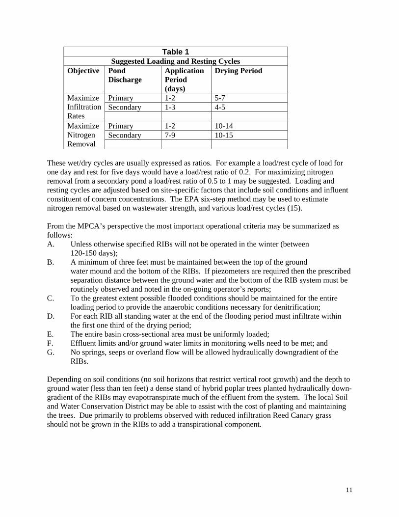
Table 1 Suggested Loading and Resting Cycles
Objective Pond Discharge
Application Period (days)
Drying Period
Primary 1-2 5-7 Secondary 1-3 4-5
Maximize Infiltration Rates
Primary 1-2 10-14 Secondary 7-9 10-15
Maximize Nitrogen Removal
These wet/dry cycles are usually expressed as ratios. For example a load/rest cycle of load for one day and rest for five days would have a load/rest ratio of 0.2. For maximizing nitrogen removal from a secondary pond a load/rest ratio of 0.5 to 1 may be suggested. Loading and resting cycles are adjusted based on site-specific factors that include soil conditions and influent constituent of concern concentrations. The EPA six-step method may be used to estimate nitrogen removal based on wastewater strength, and various load/rest cycles (15). From the MPCA’s perspective the most important operational criteria may be summarized as follows: A. Unless otherwise specified RIBs will not be operated in the winter (between
120-150 days); B. A minimum of three feet must be maintained between the top of the ground
water mound and the bottom of the RIBs. If piezometers are required then the prescribed separation distance between the ground water and the bottom of the RIB system must be routinely observed and noted in the on-going operator’s reports;
C. To the greatest extent possible flooded conditions should be maintained for the entire loading period to provide the anaerobic conditions necessary for denitrification;
D. For each RIB all standing water at the end of the flooding period must infiltrate within the first one third of the drying period;
E. The entire basin cross-sectional area must be uniformly loaded; F. Effluent limits and/or ground water limits in monitoring wells need to be met; and G. No springs, seeps or overland flow will be allowed hydraulically downgradient of the
RIBs. Depending on soil conditions (no soil horizons that restrict vertical root growth) and the depth to ground water (less than ten feet) a dense stand of hybrid poplar trees planted hydraulically down-gradient of the RIBs may evapotranspirate much of the effluent from the system. The local Soil and Water Conservation District may be able to assist with the cost of planting and maintaining the trees. Due primarily to problems observed with reduced infiltration Reed Canary grass should not be grown in the RIBs to add a transpirational component.
11
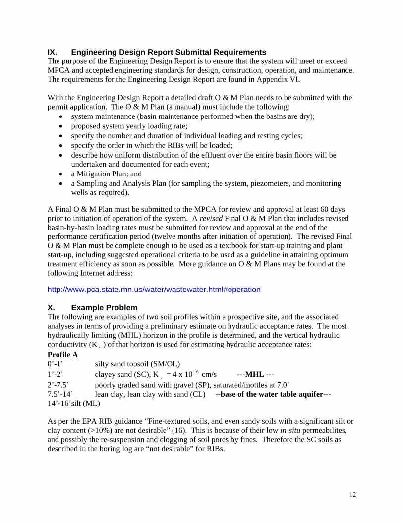
IX. Engineering Design Report Submittal Requirements The purpose of the Engineering Design Report is to ensure that the system will meet or exceed MPCA and accepted engineering standards for design, construction, operation, and maintenance. The requirements for the Engineering Design Report are found in Appendix VI. With the Engineering Design Report a detailed draft O & M Plan needs to be submitted with the permit application. The O & M Plan (a manual) must include the following:
• system maintenance (basin maintenance performed when the basins are dry); • proposed system yearly loading rate; • specify the number and duration of individual loading and resting cycles; • specify the order in which the RIBs will be loaded; • describe how uniform distribution of the effluent over the entire basin floors will be
undertaken and documented for each event; • a Mitigation Plan; and • a Sampling and Analysis Plan (for sampling the system, piezometers, and monitoring
wells as required). A Final O & M Plan must be submitted to the MPCA for review and approval at least 60 days prior to initiation of operation of the system. A revised Final O & M Plan that includes revised basin-by-basin loading rates must be submitted for review and approval at the end of the performance certification period (twelve months after initiation of operation). The revised Final O & M Plan must be complete enough to be used as a textbook for start-up training and plant start-up, including suggested operational criteria to be used as a guideline in attaining optimum treatment efficiency as soon as possible. More guidance on O & M Plans may be found at the following Internet address: http://www.pca.state.mn.us/water/wastewater.html#operation X. Example Problem The following are examples of two soil profiles within a prospective site, and the associated analyses in terms of providing a preliminary estimate on hydraulic acceptance rates. The most hydraulically limiting (MHL) horizon in the profile is determined, and the vertical hydraulic conductivity (K ) of that horizon is used for estimating hydraulic acceptance rates: v
Profile A 0’-1’ silty sand topsoil (SM/OL) 1’-2’ clayey sand (SC), K = 4 x 10 cm/s ---MHL --- v
6−
2’-7.5’ poorly graded sand with gravel (SP), saturated/mottles at 7.0’ 7.5’-14’ lean clay, lean clay with sand (CL) --base of the water table aquifer--- 14’-16’silt (ML) As per the EPA RIB guidance “Fine-textured soils, and even sandy soils with a significant silt or clay content (>10%) are not desirable” (16). This is because of their low in-situ permeabilites, and possibly the re-suspension and clogging of soil pores by fines. Therefore the SC soils as described in the boring log are “not desirable” for RIBs.
12
If the clayey sand is removed (excavated) from this location then only about 5’ of unsaturated sand would be available to transmit the relatively large volume of water away from the RIB, without causing unacceptable mounding, or seeps or springs to emerge (daylight) downgradient of the proposed RIBs. If the site is still being considered then mounding calculations need to be run with the SP hydraulic conductivity using 5’ of sand over clay (assuming that the SM is excavated). Alternatively the RIB should be constructed elsewhere. Ground water depth and aquifer thickness must be accounted for when running mounding calculations. Profile B 0’-2.5’ medium sand (SP) 2.5’-4.5’ sand, some silt (SP/SM) 4.5-7.5’ fine silty sand (SM), K = 1.9 x 10 cm/sec ---MHL--- v
3−
7.5’-25’+ fine to medium grained sand (SP), saturated/mottles 10 feet below grade Based on the boring log the hydraulic conductivity from 4.5’-7.5’ needs to be used for estimating hydraulic loading rates. Alternatively removing the top 7.5’ of soils would expose the underlying, much more permeable sands, but this may bring the top of the basin too close to the (mounded) water table. What may be inferred from analyzing the two borings (if taken together) is a high degree of soil variability, possibly even within an individual RIB. Depending on the degree of variability more borings or test pits may be needed in the proposed RIB area(s), possibly with the less favorable areas being excluded from consideration. The following is a worked example for estimating annual hydraulic loading rates. The most restrictive K within the proposed basin needs to be used for estimating hydraulic loading rates. The EPA only allows averaging of K s if there is no obvious restrictive layer (17).
v
v
Example Calculations Using Profile B K = 1.9 x 10 cm/sec; MPCA: use 10% of K ; (1.9 x 10 )(0.10) = v
3−v
3−
1.9 x 10 cm/sec; 4−
(1.9 x 10 cm/sec)/(2.54 cm/inch) = 1 x 10 inch/sec.; 4− 4−
(1.0 x 10 inch/sec)/(12 in/ft.) = 6.23 x 10 ft/sec.; 4− 6−
(6.23 x 10 ft/sec.)(60 sec/min)(60 min/hr)(24 hr/day) = 0.54 ft/day; 6−
The system is not operated between November 15 and April 15: 365 days – 150 days = 215 days; Assume loading cycle is 1/3 of loading/resting cycle: 215/3 = 71 days; (0.54 ft/day)(71 days) = 38 ft/year/basin @ 10%; If each basin was 200’ x 100’ = 20,000 ft 2 ; (20,000 ft )(38 ft/yr) = 764,787 ft 3 /yr; 2
13

(764,787 ft /yr)(7.48052 gal/ ft ) = 5,721,000 gal/yr @ 10%; 3 basins =17,163,000 gal/yr3 3 In summary (as a preliminary estimate) if ten percent of the most restrictive vertical hydraulic conductivity is used then 38 feet/ year would be allowed in each of the three RIBs, for a total of 17,163,000 gallons per year. Calculated loading rates are needed to provide an estimate of the hydraulic performance (and potential viability) of the system. Interim permit limits in the permit will be based on ten percent of insitu hydraulic conductivity tests. Final permit limits will be based on basin-by-basin loading tests run after construction of the basins, as specified in the revised Final O & M Plan that is submitted to the MPCA for review and approval at the completion of the performance certification period (twelve months after initiation of operation). The results of the post-construction basin flooding tests are multiplied by 0.1 (ten percent) to provide annual limits that includes the safety factor set by the EPA (18) and the MPCA. Individual loading cycle application rates (as opposed to annual rates) are usually set at less than 50% of the K to allow for reduced infiltration by organic matter and solids in the wastewater. Note that depending on soil variability each basin may have its own hydraulic conductivity, and associated acceptance rate.
v
14
XI. Summary and Conclusions RIBs may provide a cost-effective means of treating and dispersing municipal wastewater. A thorough site characterization is needed to determine system viability, and to estimate the hydraulic performance of the system. Empirically derived basin-by-basin loading tests conducted after the basins are constructed are used in conjunction with a “safety factor” to set final basin loading rates. Depending on nitrogen concentrations in the effluent, ground water monitoring may be required. The separation distance between the ground water mound height and the base of the RIBs must be greater than three feet, and this separation distance may need to be verified with piezometers. References 1. EPA. Process Design Manual for Land Treatment of Municipal Wastewater
Supplement on Rapid Infiltration and Overland Flow. EPA 625/1-81-013a. 1984. p. 1 2. EPA. Process Design Manual for Land Treatment of Municipal Wastewater. p. 5-3. 3. EPA. Process Design Manual Land Treatment of Municipal Wastewater.
EPA 625/1-81-013. 1981. p. 5-25 4. EPA. Process Design Manual Land Treatment of Municipal Wastewater.
EPA 625/1-81-013. 1981. p. 5-26 5. EPA. Process Design Manual for Land Treatment of Municipal Wastewater
Supplement on Rapid Infiltration and Overland Flow. EPA 625/1-81-013a. 1984. p. 47 6. Amoozegar, A. 1992. Compact Constant Head Permeameter: A Convenient Device for
Measuring Hydraulic Conductivity. Advances in Measurement of Soil Physical Properties
7. EPA. Process Design Manual for Land Treatment of Municipal Wastewater Supplement on Rapid Infiltration and Overland Flow. EPA 625/1-81-013a. 1984. p. 23
8. EPA. Process Design Manual for Land Treatment of Municipal Wastewater Supplement on Rapid Infiltration and Overland Flow. EPA 625/1-81-013a. 1984. p. 28
9. EPA. Process Design Manual for Land Treatment of Municipal Wastewater Supplement on Rapid Infiltration and Overland Flow. EPA 625/1-81-013a. 1984. p. 29
10. EPA. Process Design Manual for Land Treatment of Municipal Wastewater Supplement on Rapid Infiltration and Overland Flow. EPA 625/1-81-013a. 1984. p. 33
11. EPA. Process Design Manual Land Treatment of Municipal Wastewater. EPA 625/1-81-013. 1981. p. 5-30
12. EPA. Process Design Manual for Land Treatment of Municipal Wastewater Supplement on Rapid Infiltration and Overland Flow. EPA 625/1-81-013a. 1984. p. 38
13. Finnemore, E.J and N. N. Hantzsche. June 1983. Ground-Water Mounding Due to On-Site Sewage Disposal. Journal of Irrigation Drainage Engineering. Vol. 109, No. 2.
14. EPA. Process Design Manual Land Treatment of Municipal Wastewater. EPA 625/1-81-013. 1981. p. 5-17
15. EPA. Process Design Manual for Land Treatment of Municipal Wastewater Supplement on Rapid Infiltration and Overland Flow. EPA 625/1-81-013a. 1984. p. 51
16. EPA. Process Design Manual for Land Treatment of Municipal Wastewater Supplement on Rapid Infiltration and Overland Flow. EPA 625/1-81-013a. 1984. p. 7
17. EPA. Process Design Manual Land Treatment of Municipal Wastewater Supplement on Rapid Infiltration and Overland Flow. EPA 625/1-81-013a 10/1984. EPA p. 28
15

18. EPA. Process Design Manual Land Treatment of Municipal Wastewater Supplement on Rapid Infiltration and Overland Flow. EPA 625/1-81-013a 10/1984. EPA p. 29
16

Appendix I The RIB Permitting Process
Minnesota Pollution Control Agency staff is not required to begin review of a proposed project until it receives a complete application, including all of the necessary supporting documents. Failure to complete the application or submit the supporting documents will likely result in a delay in the issuance of the permit. The following is a description of the permitting process for a RIB system: 1. Meet, discuss proposed project with MPCA staff; 2. Submit Preliminary Proposal/Facilities Plan; 3. Submit site, soils, hydrogeologic workplans; 4. Site, soils, hydrogeologic reports approved by the MPCA; 5. MPCA approval of Preliminary Proposal/Facilities Plan; 6. Submit complete permit application, Plans and Specifications, supporting documents; 7. MPCA approval of Plans and Specifications; 8. Permit issued; 9. System constructed; 10. Conduct basin-by-basin flooding tests; 11. Final O & M Plan submitted to the MPCA 60 days prior to initiation of system operations; 12. Commence operations, 1 year certification period elapses; 13. 1 Year Certification Report and revised Final O&M Plan submitted to the MPCA; and 14. Permit modified as needed based on flooding tests. The following information is required to initiate processing the RIB permit application: 1. SDS Permit application forms found at the MPCA’s Web site.
http://www.pca.state.mn.us/water/permits/index.html# Including: • Water Quality Transmittal Form • Attachment for Municipal Facilities • Stabilization Pond Information Sheet • Attachment for Municipal Land Application
2. RIB Guidance Document attachments that include the following: • Site Evaluation (Appendix II) • Soils Report (Appendix III) • Hydrogeologic Report and checklist (Appendix IV)
3. Engineering Report (Appendix V) 4. Additional information as appropriate. The completed permit application forms, attachments and check must be sent to:
Minnesota Pollution Control Agency Attn: Beckie Olson, Permit Document Coordinator 520 Lafayette Road North St. Paul, Minnesota 55155-4194
17

To complete the permitting process the following must be submitted to and be approved by the MPCA prior to permit issuance: • The MPCA-approved site investigation, soils, and hydrogeologic reports of the proposed site; • the MPCA-approved Engineering Report. Please provide in the estimations the number and
sizes of the basins, and any buffer areas. Projections of future wastewater needs should also be incorporated into these calculations;
• as needed, a workplan and report for installing piezometers and monitoring wells; • as needed, a sampling and analysis plan for monitoring wells; and • a draft O & M Plan. The O&M Plan will need to specify individual and annual loading rates,
maintenance of the system, monitoring, etc. Interim limits in the will be based on ten percent of insitu hydraulic conductivity tests. Final limits will be based on basin-by-basin loading tests run after construction of the basins, as specified in the revised Final O & M Plan.
18
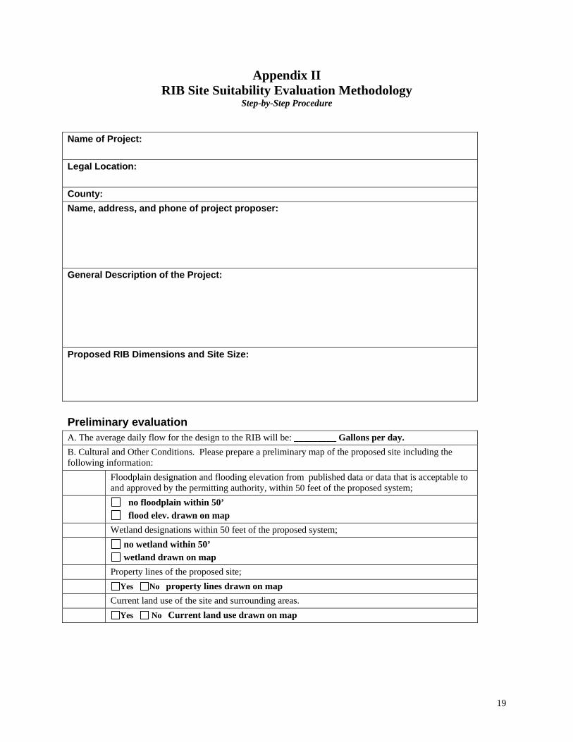
Appendix II RIB Site Suitability Evaluation Methodology
Step-by-Step Procedure
Name of Project: Legal Location: County: Name, address, and phone of project proposer: General Description of the Project: Proposed RIB Dimensions and Site Size: Preliminary evaluation A. The average daily flow for the design to the RIB will be: _________ Gallons per day. B. Cultural and Other Conditions. Please prepare a preliminary map of the proposed site including the following information: Floodplain designation and flooding elevation from published data or data that is acceptable to
and approved by the permitting authority, within 50 feet of the proposed system; no floodplain within 50’
flood elev. drawn on map Wetland designations within 50 feet of the proposed system; no wetland within 50’
wetland drawn on map Property lines of the proposed site; Yes No property lines drawn on map Current land use of the site and surrounding areas. Yes No Current land use drawn on map
19

Soil Survey Information Please list all the soil map units for the proposed site along with the following soil characteristics.
Soil Feature Soil Map Unit
_____ Soil Map Unit _____
Soil Map Unit _____
Landscape position
Flooding potential
Slope range Seasonally saturated soil level
Depth to bedrock Texture of all soil horizons
Permeability of all soil horizons
Yes No Soil survey map submitted with the location of the proposed site Note: For availability on Soil Survey maps, please refer to the local Natural Resource Conservation Service Office located in all counties in Minnesota.
Surface Information
Yes No USGS quadrangle map submitted of proposed site and surrounding area. Maps depicting:
Yes No property lines; Yes No any municipal, industrial or domestic wells within a half-mile radius of
the site; Yes No actual boring and trench locations; Yes No the proposed RIB configuration; Yes No proposed monitoring points; and Yes No any existing drain tile, and any surface water drainage features.
Note: For information on quadrangle maps, please refer to: http;//mapping.usgs.gov/mac/findmaps.html
20
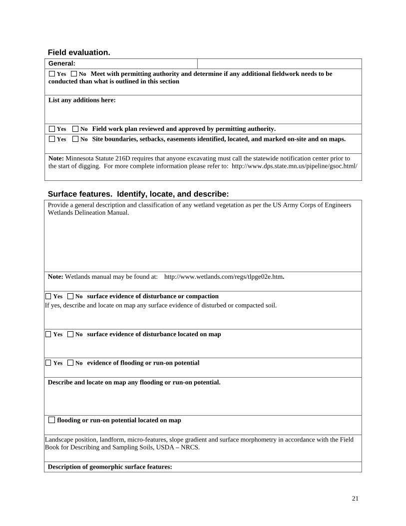
Field evaluation. General:
Yes No Meet with permitting authority and determine if any additional fieldwork needs to be conducted than what is outlined in this section
List any additions here:
Yes No Field work plan reviewed and approved by permitting authority. Yes No Site boundaries, setbacks, easements identified, located, and marked on-site and on maps.
Note: Minnesota Statute 216D requires that anyone excavating must call the statewide notification center prior to the start of digging. For more complete information please refer to: http://www.dps.state.mn.us/pipeline/gsoc.html/
Surface features. Identify, locate, and describe: Provide a general description and classification of any wetland vegetation as per the US Army Corps of Engineers Wetlands Delineation Manual. Note: Wetlands manual may be found at: http://www.wetlands.com/regs/tlpge02e.htm.
Yes No surface evidence of disturbance or compaction If yes, describe and locate on map any surface evidence of disturbed or compacted soil.
Yes No surface evidence of disturbance located on map
Yes No evidence of flooding or run-on potential Describe and locate on map any flooding or run-on potential.
flooding or run-on potential located on map
Landscape position, landform, micro-features, slope gradient and surface morphometry in accordance with the Field Book for Describing and Sampling Soils, USDA – NRCS. Description of geomorphic surface features:
21

Describe number, locations, descriptions of any hand borings: Note: The field book can be obtained from: (http://www.statlab.iastate.edu/soils/nssc/field_gd/field_gd.pdf)
Describe any discrepancies between the onsite soil information with the soil survey information.
Please resolve any discrepancies, and identify the soil information to be used for design.
Please list the elevation to bedrock, if encountered, and the determination of how that elevation was derived (please refer to Minnesota Rules 7080)
Please list the elevation to the seasonally/periodically saturated soil, if encountered, and the determination of how that elevation was derived* (please refer to MR 7080):
*If redoximorphic features are deemed not to be reflective of current day seasonally saturated levels, please submit other information to determine the depth of the seasonally saturated soil (see footnote on redoximorphic features below). Determine the elevation of the bottom of the RIB system: Please provide an assessment if the soil has been disturbed, compacted, cut filled or other unnatural condition: Please provide a description of the uniformity of the soil over the site.
Yes No Proposed site is or will be protected from disturbance, compaction or other damage by staking, fencing, posting or other effective method.
22

Appendix III RIB Site Soils Evaluation
The permittee must undertake a Site Soils Evaluation irrespective of the nitrogen management option that is selected. The purpose of the Soils Evaluation is to adequately characterize the site soils for design purposes. Soils are critical for the treatment process. The person who prepares the soils report must certify by signature that they have expertise in Soil Science as defined by education and experience (especially soil morphology) which includes having taken the Onsite Sewage Treatment Workshop Soils class or equivalent. Under some circumstances the person who designates where the soil pits are to be located may differ from the individual who actually logs the soil pits. If this occurs, then it must be noted in the Soils Report. The general procedure for characterizing site soils is as follows:
• Obtain the Natural Resources Conservation Service (NRCS) soil survey maps of the proposed RIB site and evaluate soil variability.
• For uniform soils at least one test pit per basin, or one per 10,000 square feet is suggested. If soils are more variable then more pits may be needed.
Test pits should be located immediately adjacent to the proposed RIBs, to reduce soil disturbances within the basins. Test pits are generally less than 10’ deep. As such soil borings must be used to provide information below and around the test pits as necessary. A minimum of four deeper borings are also required to determine the depth to the seasonal high water table. For mounding calculations at least two borings should extend all the way through the saturated zone. Continuous vertical observations and/or sampling of the entire vertical extent of the pit wall or boring using the ASTM D 2487 or the USDA field taxonomy must be used. The test pit and soil boring logs must contain the soil horizon, field texture, structure (grade and shape), consistence, moisture content, elevation of ground water (perched or otherwise), Munsell colors, and redoximorphic features such as gleying and mottling. A determination of seasonal high ground water table must be made, and the elevations of the pits must also be submitted. Laboratory derived or preferably in-situ permeability measurements and grain size analyses of the most transmissive and most hydraulically limiting soil horizons should be obtained and be compared with other site information. The estimated hydraulic loading rates are determined primarily from soil texture, consistency, and structure. Loading rates are also determined from saturated hydraulic conductivity, (K ) measurements made of the most and least transmissive horizon within five feet of the bottom of the proposed system, above the seasonal high water table.
sat
Combinations of these soil properties assist in determining the most limiting horizon, and provide estimates of individual and annual loading rates.
23

In-situ measurements of K using a double ring infiltrometer (or equivalent method) in most cases should be undertaken, especially on less favorable sites. It should be noted that the measured K typically represents the fastest rate that clean water will move through the soil, and that waste water infiltration rates are usually lower than the K sat .
sat
sat
Perhaps the best method to estimate hydraulic acceptance rates is to use test infiltration basins. If test infiltration basins (test areas at least 75 ft ) are used then in-situ saturated hydraulic conductivity measurements typically then would not be required.
2
Checklists and worksheets to be included with the Site Soils Evaluation Report I. Soil Descriptions
Yes No A minimum of one soil pit per basin or one per 10,000 square feet (whichever is more) of proposed site examined, with the pits located within or on the borders of the proposed system. If possible the test pits should be located outside of the proposed basins to reduce soil disturbances.
Yes No Soil profiles in pits described to a depth of 5 feet below the proposed depth of the system.
Submitted rationale for the final number of soil pits excavated and described Submitted the number, location, and depth of the test pits Submitted the number, location, and depth of deeper borings Submitted in-depth discussion of site soils Submitted Soil Description sheets (located on page 27) for all soil pits/borings.
Note: Occupational safety and health administration regulations (29 CFR 1926 Subpart P) apply to entering certain types of excavations. For more information, please refer to: http://www.osha.gov/SLTC/confinedspaces/ II. Soil Hydraulic Conductivity Testing Checklist Hydraulic conductivity testing should be undertaken for the most transmissive horizon within five feet of the bottom of the proposed system. If the least transmissive horizon observed within the test pit(s) has an anticipated conductivity that is appreciably slower than the horizon receiving the effluent then the hydraulic conductivity of the least transmissive horizon should also be determined. Which method of hydraulic conductivity testing was conducted?
Permeameter Infiltrometer Test basins Other method __________________________________
Submitted the method used to conduct the test Submitted the readings and calculations Submitted the number location and depth of the tests (min of 3 tests on the most and least
transmissive horizons) Submitted the number location and depth of any deep tests
III. Soil interpretation for system design (use as an attachment to the Soils Report)
24

Describe which surface topography and soil features will affect system siting design and performance Localized run-on of storm water drainage: Regional Flooding: Constructability (slope, gradient, etc.):
Constructability (clay percentage i.e., smearing, compaction):
Determine if the system requires any setbacks:
Yes No buildings Yes No water supply Yes No water pipes Yes No surface water setbacks
Describe any discrepancies between the onsite soil information with the soil survey information.
Please resolve any discrepancies, and identify the soil information to be used for design.
Please list the elevation to bedrock, if encountered, and the determination of how that elevation was derived (please refer to Minnesota Rules 7080)
Please list the elevation to the seasonally/periodically saturated soil, if encountered, and the determination of how that elevation was derived* (please refer to MR 7080):
Please describe the suggested hydraulic loading rates for the proposed system. Overall suitability evaluation of the site, and a description of any site limitations
25

Soil Description Worksheet
*If redoximorphic features are deemed not to be reflective of current day seasonally saturated levels, please submit other information to determine the depth of the seasonally saturated soil (see footnote on redoximorphic features below).
IV. Phosphorous Evaluation A site phosphorous evaluation must also be included in the soils report. The criteria for undertaking a phosphorous evaluation are provided below.
Table 2: Phosphorous Impact Evaluation
Soil Texture Distance to Nearest Receiving Water
Sand 2,500 feet Loam 1,500 feet Clay loam 300 feet
Site Phosphorous Evaluation Checklist
Yes No Based on the above chart, the proposed RIB is within the potential impact distance. If yes, then I am, therefore required to complete a Phosphorus Impact Study.
At a minimum, the Study shall include the following items: • A detailed discussion of the Phosphorus adsorption capacity of the soil • A detailed discussion of the expected phosphorus breakthrough to the receiving water. • Modeled results? • Supporting documentation including pertinent calculations? • Treatment options? Including BMPs, source reduction options, facility treatment options? NOTE: Designers should work with agency staff to perform this evaluation prior to application submittal.
26

USDA Methodology
(use one sheet per test pit or boring) Date: Vegetation: Project:
Location:
Landscape:
Soil Survey Map Unit: Slope Form: Disturbed Soil : Yes No Slope: Type of Observation: pit boring auguring Floodplain: Yes No
Dep
th (i
n)
Hor
izon
D
esig
natio
n
Coa
rse
Frag
men
ts
Tex
ture
(a
bund
ance
, si
ze, c
ontr
ast)
Mat
rix
Col
or
(abu
ndan
ce,
size
, con
tras
t)
Red
ox F
eatu
res
(abu
ndan
ce,
size
, con
tras
t)
Stru
ctur
e (S
hape
, Siz
e,
Gra
de)
Con
sist
ency
Roo
ts
(abu
ndan
ce a
nd
size
)
Pore
s (Q
uant
ity
and
size
)
Con
cret
ions
N
odul
es
Bou
ndar
y
Backhoe test pit ground surface elevation
Depth to Seasonally Saturated Soil
(see footnote below)
Depth of Standing Water in Hole/Pit (if any)
Depth to Bedrock (if any)
Proposed Bottom of System Elevation
Estimated Infiltrative Loading Rate
Weather and light conditions:
27

Appendix IV
RIB Hydrogeologic Report and Checklist A detailed Hydrogeologic Investigation Report and ground water monitoring report will be required for RIB systems unless the conditions described in Option 1 (see Section II) are met. The purpose of the report is to document hydrogeologic properties that include depth to ground water, ground-water flow direction, estimated ground water flow rates, ambient geochemistry, proximal receptors, the potential for unacceptable ground water mounding, and to establish a ground water monitoring network. The person who prepares the report must certify by signature that they have expertise in Hydrogeology as defined by education and experience. The report must summarize existing (published) information, and information obtained in the field. If ground water monitoring is required then at least one monitoring well must be installed in the approximate up-gradient location, and sampled three times prior to permitting. The purpose of sampling prior to permitting is to ensure that the permit reflects ambient conditions, so limits will not have to be changed once the system becomes operational. Although not required to obtain a permit a Hydrogeologic Investigation Work Plan (Work Plan) should be submitted to the MPCA prior to initiating the field work. If the field work is performed without MPCA review and approval of a Work Plan, and it does not meet minimum requirements, then more field work will be required. Typically for a RIB system a minimum of four deep borings are completed (in addition to the test pits required with the soils work) along with the three monitoring wells (a minimum of one up-gradient, and two down-gradient). Down-gradient monitoring wells may be located no further than the property boundary. Due to discharge flow dynamics the further from the system the monitoring wells are located, the more monitoring wells may be required to adequately monitor the site. Under certain conditions constricted lateral movement of the effluent in the soil matrix may cause mounding of ground water. For proper soil based treatment the system must maintain a minimum of a three foot aerobic zone below the bottom of the RIBs. Mounding calculations are suggested for all RIB systems. Under certain circumstances, such as systems located in coarse soils with a deep water table, mounding analyses may not be necessary. Alternative design approaches may be used to prevent and minimize the potential for mounding. At minimum, either mounding calculations or a rationale for why mounding calculations are not necessary for the project, must be submitted with the hydrogeologic evaluation. Additional mounding caused by adjacent basins also must be taken into account. Unless it can be clearly demonstrated that unacceptable mounding will not occur, piezometers will be required. The purpose of the piezometers is to measure mounding during system operations, and to maintain an aerobic zone under the system during operation.
29

The proposed locations and rationale for the piezometers needs to be submitted to the MPCA. A MPCA-approved workplan will be needed for piezometer installation. If ground water monitoring is required, then a ground water sampling and analysis plan (SAP) will need to be submitted to the MPCA for review and approval. Depending on the proximity of the RIBs to surface waters additional standards may need to be applied to the monitoring points. A template for a SAP is available at the following Internet address: http://www.pca.state.mn.us/water/pubs/gwprocwells.pdf Estimating Mound Height For sites where unacceptable mounding may be an issue estimating the extent of mounding is required to ensure that ground water does not rise to within three feet of the bottom of the system during loading. Mounding calculations must also consider mounding influences from adjacent basins. Deep borings must be conducted to a minimum of 10 feet below the proposed system bottom to determine soil properties. In-situ hydraulic conductivity tests (slug tests, pump tests) conducted sufficiently below the water table to conduct the tests may also be suggested. If not, a minimum of three laboratory hydraulic conductivity measurements of the most and least transmissive horizons must be made. Recommended Mounding Calculation - Finnemore and Hantzche zm = Mound height in center of system (ft) zm = IC * (L/4)^n * (1/ K *h)^0.5n * (t/Sy)^1-0.5n h
t = Time (days): (365 days/year)-(150 days not in use) = 215 days I = Average daily loading rate (ft/day) = Design loading rate/215 C = from chart below L = Length of system (ft) n = from chart below K = from hydraulic testing h = ho + zm/2 Sy = Specific Yield ho = Aquifer thickness (ft) zm (guess) = estimated mound height Table 3: Finnemore and Hantzche Length to Width Ratios
L/W Ratio C N 1 3.4179 1.7193 2 2.0748 1.7552 4 1.1348 1.7716 8 0.5922 1.7793
Note: The two dimensions of an RIB (length and width) is included in the Length to Width (L/W) Ratio found in the "c" and "n" values of the formula
30

The final result of this calculation is to estimate if the proposed system will have at least three feet of separation between the bottom of the system and the predicted mound (including a capillary fringe) height. Hydrologic Report Requirements The Hydrogeologic Report must include a detailed discussion of the following elements:
• Physiographic setting/topography/slopes; • Hydrology; • Geology and hydrogeology to include descriptions of local, intermediate and regional
ground water flow regimes; • Depth to current and seasonal ground water; • Hydraulic gradient; • Hydraulic conductivity; • The directions and rates of ground water flow; • Geologic cross-sectional analysis of the site including the presence of deeper limiting
layers, perched water tables, bedrock, karst, etc.; • Background ground water quality data; • Potential or actual receptors; and • Mounding analyses
The following checklist must be attached to the Hydrogeologic Report to ensure that all of the required elements described above are included in the Report.
Completed? COMMENTS MPCA
USE Required Elements for a RIB Hydrogeologic Investigation Report YES NO
SUBMITTAL PAGE No.
1. A USGS topographic map showing: • the proposed location of the system
• the property boundary
• the borings, test pits, piezometer and monitoring well locations
• domestic or municipal wells within 1/2 mile radius of theproposed system
• any wellhead protection areas within a mile radius of the proposed system
2. Discussion, logs of deeper borings
3. Proposed municipal or domestic well setbacks
4. Narrative on the physiographic setting/topography/slopes
5. Summary of the soils investigation
31

Completed? COMMENTS MPCA USE
Required Elements for a RIB Hydrogeologic Investigation Report YES NO
SUBMITTAL PAGE No.
6. Local, intermediate and regional hydrology, Including
site drainage
7. Proximity to a flood plain
8. Geologic narrative (local, intermediate and regional)
9. Perpendicular geologic cross-sections including incorporating the results of the soils investigation
10. Hydrogeologic narrative (vertical and horizontal, local, intermediate and regional ground water flow)
11. Potentiometric surface map showing alignment (perpendicular) of system in relation to ground water flow direction
12. Discussion, results of the phosphorous evaluation done in Soils Report
13. Discussion, results of ground water mounding analyses
14. Recommendations based on the report
15. Discussion on K , K , and K v h sat
16. Mounding analyses
32
Appendix V
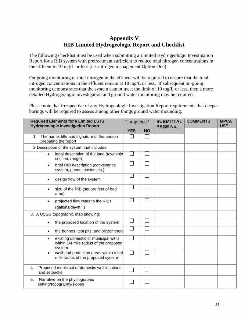
RIB Limited Hydrogeologic Report and Checklist The following checklist must be used when submitting a Limited Hydrogeologic Investigation Report for a RIB system with pretreatment sufficient to reduce total nitrogen concentrations in the effluent to 10 mg/L or less (i.e. nitrogen management Option One). On-going monitoring of total nitrogen in the effluent will be required to ensure that the total nitrogen concentrations in the effluent remain at 10 mg/L or less. If subsequent on-going monitoring demonstrates that the system cannot meet the limit of 10 mg/L or less, then a more detailed Hydrogeologic Investigation and ground water monitoring may be required. Please note that irrespective of any Hydrogeologic Investigation Report requirements that deeper borings will be required to assess among other things ground water mounding.
Completed? COMMENTS MPCA USE
Required Elements for a Limited LSTS Hydrogeologic Investigation Report YES NO
SUBMITTAL PAGE No.
1. The name, title and signature of the person
preparing the report
2. Description of the system that includes:
• legal description of the land (townshipsection, range)
• brief RIB description (conveyance system, ponds, basins etc,)
• design flow of the system
• size of the RIB (square feet of bed area)
• projected flow rates to the RIBs (gallons/day/ft ) 2
3. A USGS topographic map showing:
• the proposed location of the system
• the borings, test pits, and piezometers
• existing domestic or municipal wells within 1/4 mile radius of the proposed system
• wellhead protection areas within a halfmile radius of the proposed system
4. Proposed municipal or domestic well locations and setbacks
5. Narrative on the physiographic setting/topography/slopes
33
Completed? COMMENTS MPCA USE
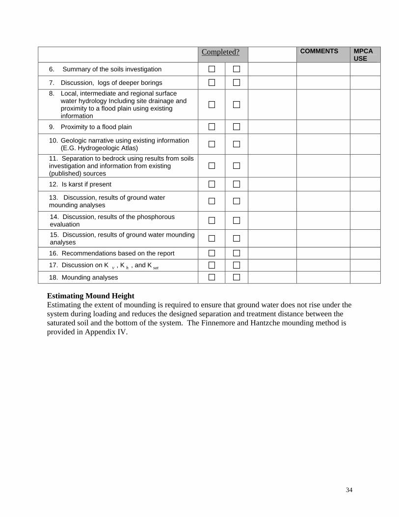
6. Summary of the soils investigation
7. Discussion, logs of deeper borings 8. Local, intermediate and regional surface
water hydrology Including site drainage and proximity to a flood plain using existing information
9. Proximity to a flood plain
10. Geologic narrative using existing information (E.G. Hydrogeologic Atlas)
11. Separation to bedrock using results from soils investigation and information from existing (published) sources
12. Is karst if present
13. Discussion, results of ground water mounding analyses
14. Discussion, results of the phosphorous evaluation
15. Discussion, results of ground water mounding analyses
16. Recommendations based on the report
17. Discussion on K , K , and K v h sat
18. Mounding analyses Estimating Mound Height Estimating the extent of mounding is required to ensure that ground water does not rise under the system during loading and reduces the designed separation and treatment distance between the saturated soil and the bottom of the system. The Finnemore and Hantzche mounding method is provided in Appendix IV.
34

Appendix VI RIB Engineering Report Requirements Checklist
The design professional shall certify (by signature) to the following general conditions:
• The plans and specifications including the Engineering Report were prepared under the direct supervision of a Registered Professional Engineer licensed in the State of Minnesota.
• The design professionals preparing the Engineering Report are qualified to design wastewater systems.
• The wastewater system will not discharge directly to the surface of the ground or to surface waters.
• That a minimum distance of three feet must exist between the discharge point and the seasonal high water table and/or the estimated mound height.
• That the monitoring wells (if used) are installed according to the Minnesota Water Well Construction Code, Minnesota Rules ch 4725.
Completed ? COMMENTS MPCA
USE Required Elements for a RIB Engineering Report YES NO
SUBMITTAL PAGE No.
1. The name, title and signature of the
person preparing the report
2. Description of the system that includes:
• location
• environmental setting
• demographics
• wastewater characteristics
3. Design flow
4. Description of design loadings with appropriate design manual references
5. A description of the proposed wastewater treatment system referencing the plans and specifications.
• description of flow monitoring methods
• description of treatment technology
• describe and size all pumps and appurtenances
• describe RIB design
6. Plans and Specifications
7. Operations and Maintenance Plan
35