gtc-600 - tadano mantis cranes · gtc-600 66 ton at 10 feet (60t at 3.0m) boom 4-section full power...
TRANSCRIPT

GTC-60066 Ton Telescopic Boom Crawler Crane
GENERAL DATACRANE CAPACITY 66 ton at 10 feet
(60t at 3.0m)BOOM 4-section,
37’ 8” – 118’ 1”(11.5 m – 38.0 m)
DIMENSIONOverall Length 46’ 1” (14.08 m)Overall Width (tracks extended) 16’ 2” (4.92 m)Overall Width (tracks retracted) 10’ 9” (3.27 m)Overall Width (tracks removed) 9’ 8” (2.95 m)Overall Height (working) 12’ 9” (3.89 m)MASSGross Vehicle Mass (Standard Equipment Package)
140,086 lb(63,387 kg)
Maximum Counterweight Upper = 30,000 lb(13,608 kg)
Carbody = 13,226 lb(6,000 kg)
PERFORMANCETravel Speed 0.8 mph (1.3 km/hr)/
2.5 mph (4.0 km/hr)Gradeability 78%
CRANE SPECIFICATIONMODEL CAPACITYGTC-600 66 ton at 10 feet (60t at 3.0m)
BOOM4-section full power telescoping boom with 2 extension modes. System consists of three double acting hydraulic cylinders with load holding valves and extension and retraction cables.• Retracted Length: 37’ 8” (11.5m) • Extended Length: 118’ 1” (38.0 m) • Extension Time: 125 s• Elevating Angles: -1.5° to 80.0° • Elevating Time: 89 s• Max Lifting Height: 125’ 3” (38.2m)• Boom Head: Six, 19.5 inch (495 mm) diameter cast nylon main
sheaves on heavy-duty roller bearings. Two, 17.5” (445mm) diameter cast nylon lead in sheaves on heavy-duty roller bearings). Designed for quick reeving of head and load block.
AUXILIARY BOOM HEADQuick reeve, single 17.5 inch (445 mm) diameter high-strength, cast nylon sheave mounted on a heavy-duty roller bearing. Allows single part reeving.
COUNTERWEIGHT 4 piece counterweight design. Two upper counterweight configurations• “A” Configuration = 30,000lb (13,608 kg)• “B” Configuration = 15,000lb (6,804 kg)• Two carbody counterweights, 6,613lb (3,000kg) eachWINCHESPlanetary geared two-speed winch includes a hydraulic motor, multi-disc internal brake and counterbalance valve. Drum rotation indicator is included (complete winch performance specs on Page 3)• Main Winch o Rope Diameter and Length: 3/4 in x 650 ft (19mm x 198m) o Single line pull: 19,830 lb (88.2 kN)(first layer) o Single line speed: 368 ft/min (112.2 m/min)(4th layer)• Auxiliary Winch o Rope Diameter and Length: 3/4 in x 410 ft (19mm x 125m) o Single line pull: 19,830 lb (88.2 kN)(first layer) o Single line speed: 368 ft/min (112.2 m/min)(4th layer)
TRAVEL Each side frame contains a pilot controlled, two-speed track drive with hydraulic axial piston motor and parking brake. Travel system provides skid steering and counter rotation.• Travel speed - Low: 0.8 mph (1.3 km/hr) High: 2.5 mph (4.0 km/hr)• Gradeability (unladen): 78%• Unladen Ground Pressure: 9.8 psi (0.67 kg/cm2)SWINGGear motor driving a planetary gear reducer with a shaft mounted pinion, external gear shear ball slew bearing bolted to the superstructure and the carbody allows the superstructure to rotate 360°• Swing Speed: 0 - 2.4 rpm• Swing Parking Brake: Spring applied failsafe brake with hydraulic
release that is controlled from the operators cab• Swing Service Brake: Hydraulically applied, controlled through foot
actuated pedal• House Lock System o 4-position house lock (boom over front, rear or either side).
Actuated from the operator’s cab.
LOAD MOMENT INDICATORTADANO AML-C Rated Capacity Limiter and Anti-Two Block system• OPTI-WIDTH™ - OPTIMAL lifting performance at any track WIDTH• Control function shutdown. Audible and visual warnings• LCD screen provides a continuous display of working boom length,
boom angle, working load radius, tip height, swing position, parts-of-line (operator set), machine track configuration, relative load moment, maximum permissible load and actual load.
• Anti-two block weight allows quick reeving of hook block• Operator configurable working range limits with automatic soft stop.
SPECIFICATION SHEET NO. TMC-DI-734-14 02/17

2
GTC-60066 Ton Telescopic Boom Crawler Crane SPECIFICATION SHEET NO. TMC-DI-734-14 02/17
Specifications are subject to change without prior notice.
FRAMEThe frame is an all-steel, welded structure, precision machined to accept attachment of the boom and swing components.OPERATORS CABFully-enclosed, air conditioned all-steel modular cab with lockable sliding door, acoustical lining, anti-slip floor and tinted safety glass.• Cab tilts 20°.• Rear view, winch view and right side view video cameras• Three remote control work lights.• Vent window in the rear of the cab.• Grab bars and steps are located for easy access to the cab.• Defroster, heater, circulating fan• 2-speed windshield wiper, top glass wiper• Six-way adjustable fabric seat with headrest, seat belt• Dome light• Dry-chemical fire extinguisher• Four-way electronic armrest mounted joysticks control swing, main
winch, auxiliary winch, boom hoist and boom extend. Foot pedalscontrol the travel and swing service brake functions. Swing brakepedal is hydraulic.
• Selectable modes for Fine Control and Travel. Travel function can beoperated by foot pedals or joystick.
• Seat termination switch immediately disable all hydraulic functions asthe operator rises from the seat. Functions can also be disabled byswitch on console.
• Dash instrumentation: tachometer, hour meter, fuel gauge, andDEF level gauge. Indicators are provided for crane level, swingposition, load moment, drum rotation, air filter restriction, engine oiltemperature and pressure, hydraulic oil temperature and level, andhydraulic and air filter restriction, and low voltage.
ENGINE • Make/ Model: Cummins QSB6.7• Type: 6 Cylinder, Water cooled, 4 Cycle• Aspiration: Turbocharged and Aftercooled• Max.Output: 310 hp (231 kW) @ 2200 RPM• Max Torque: 770 Lb-ft (1,044 Nm) @ 1500 RPM• Piston Disp: 6.7 L• Emission Cert: U.S. EPA Tier 4f, Euromot Stage IV• Alternator: 70 ampELECTRICAL SYSTEM24 VDCFUEL SYSTEM• Capacity: 85 gallon (321 liter)• Filtration: Inline fuel/water separator and engine mounted fuel filterSIDE FRAMESTwo welded steel side frames are paired with a track group. The side frames extend and retract hydraulically and are controlled from the cab.• Track Rollers: Two top and thirteen bottom sealed rollers on each
track frame Idler: Oil filled, self lubricating with nitrogen type tensioner• Track Shoes: 35.4 inch (900 mm), 3-bar semi grouser
HYDRAULIC SYSTEM• Hydraulic Pumps: Two high pressure, variable axial piston pumps with
load sense and power limiting control for crane functions. One axialpiston pump for swing function. One gear pump for cooling loop.
• Directional Valves: Multiple pressure and flow compensated valves with integrated relief valves controlled by electrical signals.
• Pump output: 154 gpm (582 l/min) @ 2200 RPM engine speed.5,000 psi (345 bar) maximum pressure
• Reservoir: 227 gallon (861 liter) capacity, spin-on filler/ breather, sightgauge, cleanout, and sump drain.
• Filtration: Three 5 micron, full flow tank mounted return filters with electrical clogging indicator. 3 micron pilot oil in-line pressure filter
• Diagnostic Ports: Provided for system, load sense, and pilot pressureBI-FOLD JIB
o Main jib• Total Length: 33.1 ft (10.1m) • Offset Angles: 3.5°, 25° & 45°• Max. Lifting Height: 157.9 ft (48.1 m)
o Fly jib• Total Length: 58.1ft (17.7m) • Offset Angles: 3.5°, 25° & 45°• Max. Lifting Height: 182.1 ft (55.5 m)
OPTIONAL EQUIPMENT
• Offset Angles: 3.5° & 30°• Heavy lift jib
• Total Length: 8.2ft (2.5 m)• Max. Lifting Height: 126.6 ft (38.6m)
• Hook blockso 66 ton (60t) quick reeve hook block – Six, 19.5 in (495mm) steel
sheaves, swivel hook and safety latcho 55 ton (50t) quick reeve hook block – three, 19.5 in (495mm)
steel sheaves, swivel hook and safety latcho 22 ton (20t) quick reeve hook block – one, 19.5 in(495mm) steel
sheave, swivel hook and safety latch• Overhaul ball – 8.8 ton (8t) with swivel hook & safety latch• 360 degree house lock. Actuated from the operator’s cab.• Track Shoes: 31.5 inch (800 mm) steel flat shoe. • Auger: Hydraulic auger boom package includes auger motor, hoses,
fasteners, and stowage bracket assembly mounted to the 2nd stage section of boom for variable radius drilling.
• Tool Circuit: Provides 5 gpm (23 l/min) and 10 gpm (45 l/min) at 2,500 PSI (176 bar) through a 50 foot (15.2m) twin hose reel with quick disconnect fittings to operate open center tools.
• High Flow Tool Circuit: Provides 45 gpm (170 l/min) at 4800 PSI(330 bar)
• Controlled Free Fall Hoists: Winches are available in controlled free fall configurations.
• Cold Weather Packages: Cold weather options are available for operation to -40°C (Consult factory for application support)
• Work Platform: Model WP750 – 36 in x 72 in (0.9m x 1.8m) , all steel, welded, two person platform with maximum capacity of 750 lbs (340 kg).
• Radio control package.• Anemometer: boom mounted wireless anemometer with cab display.• Central lubrication system.
3
GTC-60066 Ton Telescopic Boom Crawler Crane SPECIFICATION SHEET NO. TMC-DI-734-14 02/17
Specifications are subject to change without prior notice.
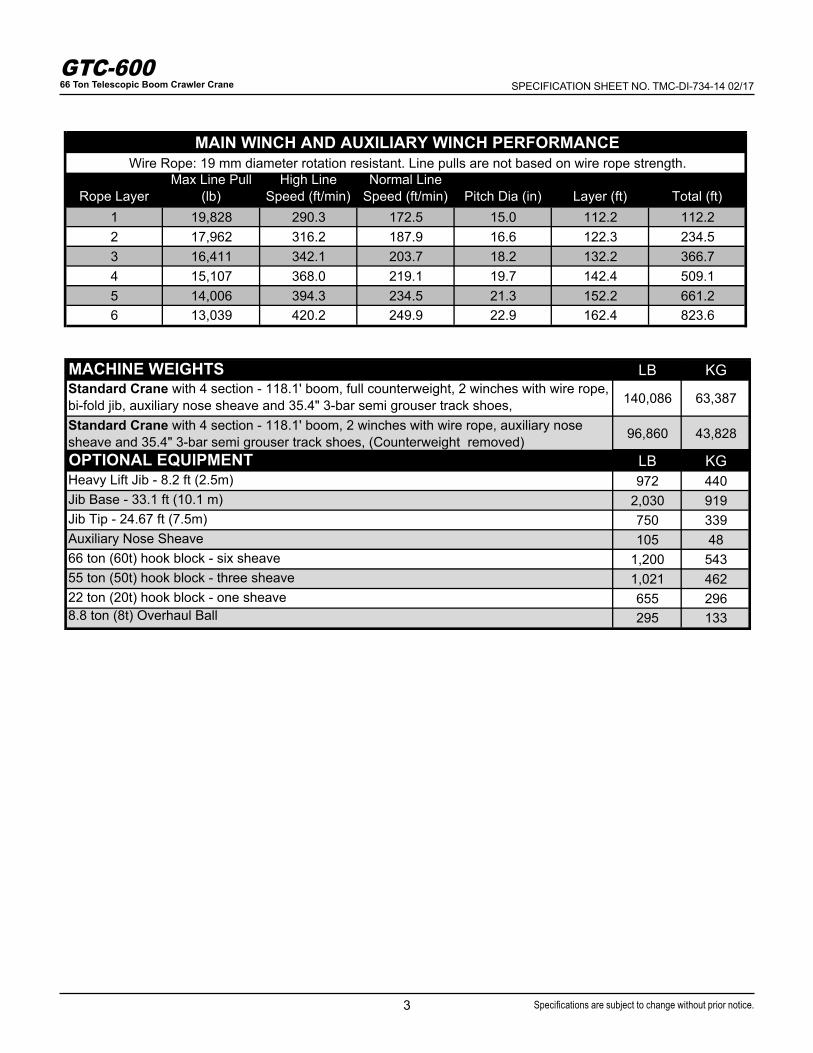
Rope LayerMax Line Pull
(lb)High Line
Speed (ft/min)Normal Line
Speed (ft/min) Pitch Dia (in) Layer (ft) Total (ft)1 19,828 290.3 172.5 15.0 112.2 112.22 17,962 316.2 187.9 16.6 122.3 234.53 16,411 342.1 203.7 18.2 132.2 366.74 15,107 368.0 219.1 19.7 142.4 509.15 14,006 394.3 234.5 21.3 152.2 661.26 13,039 420.2 249.9 22.9 162.4 823.6
MAIN WINCH AND AUXILIARY WINCH PERFORMANCE Wire Rope: 19 mm diameter rotation resistant. Line pulls are not based on wire rope strength.
MACHINE WEIGHTS LB KGStandard Crane with 4 section - 118.1' boom, full counterweight, 2 winches with wire rope, bi-fold jib, auxiliary nose sheave and 35.4" 3-bar semi grouser track shoes, 140,086 63,387
Standard Crane with 4 section - 118.1' boom, 2 winches with wire rope, auxiliary nose sheave and 35.4" 3-bar semi grouser track shoes, (Counterweight removed) 96,860 43,828
OPTIONAL EQUIPMENT LB KGHeavy Lift Jib - 8.2 ft (2.5m) 972 440Jib Base - 33.1 ft (10.1 m) 2,030 919Jib Tip - 24.67 ft (7.5m) 750 339Auxiliary Nose Sheave 105 4866 ton (60t) hook block - six sheave 1,200 54355 ton (50t) hook block - three sheave 1,021 46222 ton (20t) hook block - one sheave 655 2968.8 ton (8t) Overhaul Ball 295 133

4
GTC-60066 Ton Telescopic Boom Crawler Crane SPECIFICATION SHEET NO. TMC-DI-734-14 02/17
Specifications are subject to change without prior notice.
DIMENSIONS
5
GTC-60066 Ton Telescopic Boom Crawler Crane SPECIFICATION SHEET NO. TMC-DI-734-14 02/17
Specifications are subject to change without prior notice.
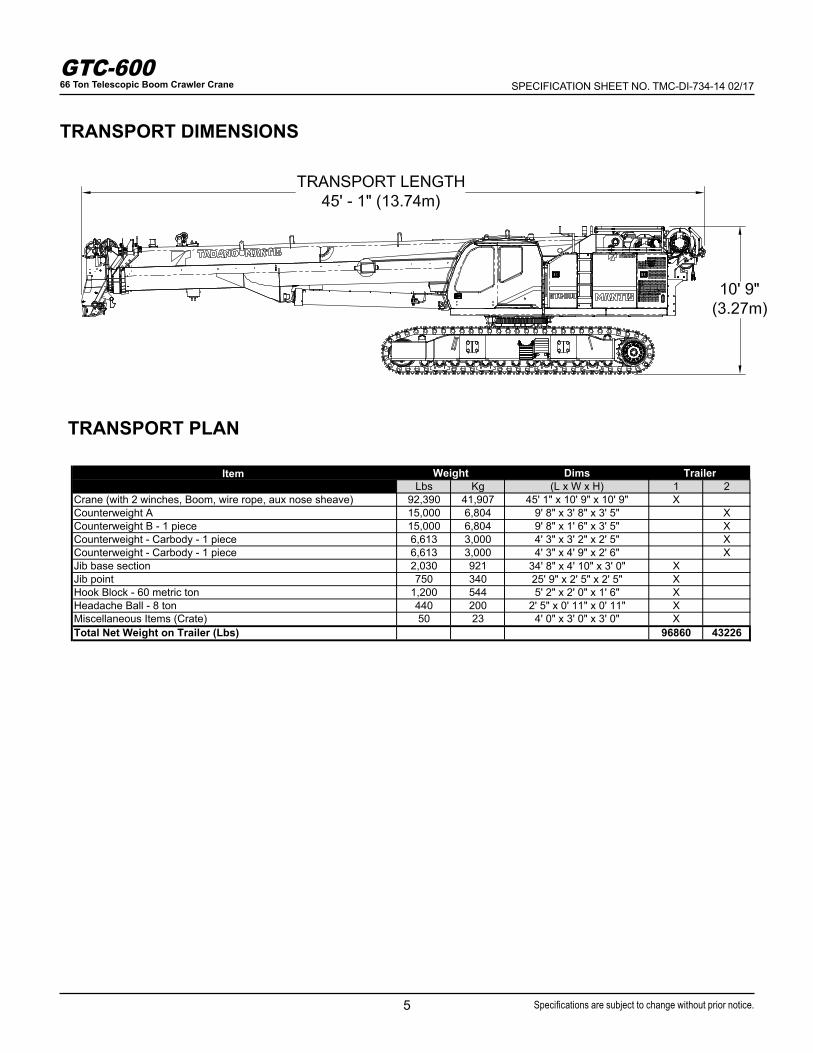
TRANSPORT DIMENSIONS
TRANSPORT PLAN
DimsLbs Kg (L x W x H) 1 2
Crane (with 2 winches, Boom, wire rope, aux nose sheave) 92,390 41,907 45' 1" x 10' 9" x 10' 9" XCounterweight A 15,000 6,804 9' 8" x 3' 8" x 3' 5" XCounterweight B - 1 piece 15,000 6,804 9' 8" x 1' 6" x 3' 5" XCounterweight - Carbody - 1 piece 6,613 3,000 4' 3" x 3' 2" x 2' 5" XCounterweight - Carbody - 1 piece 6,613 3,000 4' 3" x 4' 9" x 2' 6" XJib base section 2,030 921 34' 8" x 4' 10" x 3' 0" XJib point 750 340 25' 9" x 2' 5" x 2' 5" XHook Block - 60 metric ton 1,200 544 5' 2" x 2' 0" x 1' 6" XHeadache Ball - 8 ton 440 200 2' 5" x 0' 11" x 0' 11" XMiscellaneous Items (Crate) 50 23 4' 0" x 3' 0" x 3' 0" XTotal Net Weight on Trailer (Lbs) 96860 43226
Item Weight Trailer

6
GTC-60066 Ton Telescopic Boom Crawler Crane SPECIFICATION SHEET NO. TMC-DI-734-14 02/17
Specifications are subject to change without prior notice.
TRANSPORT DIMENSIONS

7
GTC-60066 Ton Telescopic Boom Crawler Crane SPECIFICATION SHEET NO. TMC-DI-734-14 02/17
Specifications are subject to change without prior notice.
TRANSPORT DIMENSIONS

8
GTC-60066 Ton Telescopic Boom Crawler Crane SPECIFICATION SHEET NO. TMC-DI-734-14 02/17
Specifications are subject to change without prior notice.
WORKING RANGE DIAGRAM

9
GTC-60066 Ton Telescopic Boom Crawler Crane SPECIFICATION SHEET NO. TMC-DI-734-14 02/17
Specifications are subject to change without prior notice.
WORKING RANGE DIAGRAM - HEAVY LIFT JIB

LOAD CHARTS LOADS IN lb x 1000
10
GTC-60066 Ton Telescopic Boom Crawler Crane SPECIFICATION SHEET NO. TMC-DI-734-14 02/17
Specifications are subject to change without prior notice.
Load chart data is for reference, load charts supplied in the crane cab shall be used for lift planning.
RADIUS RADIUS
(ft) 37.7 51.1 64.5 77.9 91.3 104.7 118.1 (ft)
10 132.3 115.5 78.8 38.6 10
12 121.6 115.5 77.6 38.6 12
15 96.7 95.8 76.1 37.1 36.4 15
20 69.7 66.4 63.6 37.1 36.2 34.5 29.8 20
25 49.9 47.5 45.6 37.1 36.1 34.2 29.4 25
30 38.6 37.3 36.1 35.5 35.5 33.7 26.2 30
35 31.1 31.1 29.6 28.5 28.5 23.5 35
40 25.8 25.9 25.9 23.6 23.7 21.3 40
45 22.0 22.0 19.8 20.0 19.4 45
50 19.0 19.0 16.9 17.1 17.4 50
55 16.6 16.6 14.5 15.2 15.1 55
60 14.6 12.6 13.9 13.2 60
65 13.1 11.5 12.3 11.6 65
70 11.8 10.7 10.9 10.3 70
75 10.0 9.8 9.1 75
80 9.3 8.8 8.1 80
85 7.9 7.2 85
90 7.1 6.5 90
95 6.5 5.8 95
100 5.2 100
105 4.7 105
110 4.2 110
PARTS OF LINE 10 8 8 4 4 4 2 PARTS OF
LINE
ALL LOADS IN lb x 1000
MAIN BOOM with TRACKS FULLY EXTENDED ‐ 360° UP to 1.5° SLOPE
30,000 lb MAIN COUNTERWEIGHT AND 13,200 lb CARBODY COUNTERWEIGHTMAIN BOOM LENGTH (ft)

LOAD CHARTS LOADS IN lb x 1000
11
GTC-60066 Ton Telescopic Boom Crawler Crane SPECIFICATION SHEET NO. TMC-DI-734-14 02/17
Specifications are subject to change without prior notice.
Load chart data is for reference, load charts supplied in the crane cab shall be used for lift planning.
RADIUS RADIUS
(ft) 37.7 51.1 64.5 77.9 91.3 104.7 118.1 (ft)10 130.2 96.0 77.0 38.6 1012 119.0 96.0 77.0 38.6 1215 90.3 80.5 72.8 37.1 36.4 1520 60.7 54.9 50.5 37.1 36.2 31.4 25.3 2025 45.3 41.0 37.9 37.1 36.1 31.4 25.3 2530 36.3 34.5 33.4 30.6 29.0 28.2 23.3 3035 27.6 27.6 26.8 23.9 23.4 21.2 3540 22.5 23.3 22.7 20.0 19.8 19.4 4045 20.1 19.6 17.1 16.9 16.9 4550 17.6 17.1 14.7 15.4 14.7 5055 15.7 15.1 12.9 13.8 12.9 5560 13.5 11.9 12.3 11.4 6065 12.2 11.1 10.9 10.1 6570 11.2 10.4 9.8 9.0 7075 9.7 8.8 8.0 7580 9.0 8.0 7.1 8085 7.2 6.4 8590 6.6 5.8 9095 6.1 5.2 95100 4.7 100105 4.3 105110 3.9 110
PARTS OF LINE
10 8 8 4 4 4 2 PARTS OF LINE
30,000 lb MAIN COUNTERWEIGHT AND 13,200 lb CARBODY COUNTERWEIGHTMAIN BOOM LENGTH (ft)
ALL LOADS IN lb x 1000
MAIN BOOM with TRACKS FULLY EXTENDED ‐ 360°UP to 4° SLOPE

LOAD CHARTS LOADS IN lb x 1000
12
GTC-60066 Ton Telescopic Boom Crawler Crane SPECIFICATION SHEET NO. TMC-DI-734-14 02/17
Specifications are subject to change without prior notice.
Load chart data is for reference, load charts supplied in the crane cab shall be used for lift planning.
RADIUS RADIUS
(ft) 37.7 51.1 64.5 77.9 91.3 104.7 118.1 (ft)
10 132.3 115.5 78.8 38.6 10
12 121.6 115.5 77.6 38.6 12
15 96.7 95.8 76.1 37.1 36.4 15
20 70.9 70.0 67.4 37.1 36.2 34.5 29.8 20
25 55.2 54.3 53.7 37.1 36.1 34.2 29.4 25
30 44.7 43.8 42.8 37.1 36.1 33.7 26.2 30
35 37.3 36.1 34.5 32.9 29.9 23.5 35
40 31.2 31.1 28.3 28.5 26.7 21.3 40
45 26.4 24.7 24.0 24.0 19.4 45
50 22.8 22.7 20.5 20.7 17.9 50
55 20.0 19.9 17.7 17.9 16.5 55
60 17.6 15.5 15.7 15.3 60
65 15.7 13.6 13.8 14.2 65
70 14.2 12.0 12.3 12.6 70
75 10.7 11.3 11.3 75
80 9.6 10.6 10.1 80
85 9.8 9.1 85
90 8.9 8.2 90
95 8.1 7.4 95
100 6.7 100
105 6.1 105
110 5.6 110
PARTS OF LINE 10 8 8 4 4 4 2 PARTS OF
LINE
MAIN BOOM with TRACKS RETRACTED ‐ OVER FRONT/REARUP to 1.5° SLOPE
30,000 lb MAIN COUNTERWEIGHT AND 13,200 lb CARBODY COUNTERWEIGHTMAIN BOOM LENGTH (ft)
ALL LOADS IN lb x 1000

LOAD CHARTS LOADS IN lb x 1000
13
GTC-60066 Ton Telescopic Boom Crawler Crane SPECIFICATION SHEET NO. TMC-DI-734-14 02/17
Specifications are subject to change without prior notice.
Load chart data is for reference, load charts supplied in the crane cab shall be used for lift planning.
RADIUS RADIUS
(ft) 37.7 51.1 64.5 77.9 91.3 104.7 118.1 (ft)10 * * * * 1012 * * * * 1215 * * * * * 1520 42.0 * * * * * * 2025 30.9 31.5 28.0 * * * * 2530 24.1 24.6 24.7 24.7 22.4 23.6 22.3 3035 19.8 20.0 20.1 20.2 19.2 18.4 3540 16.4 16.6 16.7 16.9 16.0 15.2 4045 14.0 14.1 14.3 13.5 12.7 4550 12.0 12.1 12.3 11.5 10.8 5055 10.4 10.5 10.7 9.9 9.2 5560 9.1 9.3 8.6 7.9 6065 8.0 8.2 7.4 6.8 6570 7.2 7.2 6.5 5.8 7075 6.4 5.6 5.0 7580 5.7 4.9 4.3 8085 4.3 3.7 8590 3.8 3.1 9095 3.3 2.5 95100 2.0 100105 1.5 105110 1.1 110
PARTS OF LINE
10 8 8 4 4 4 2 PARTS OF LINE
MAIN BOOM with TRACKS FULLY RETRACTED ‐ OVER SIDEUP to 1.5° SLOPE
30,000 lb MAIN COUNTERWEIGHT AND 13,200 lb CARBODY COUNTERWEIGHTMAIN BOOM LENGTH (ft)
ALL LOADS IN lb x 1000
LOAD CHARTS LOADS IN lb x 1000
14
GTC-60066 Ton Telescopic Boom Crawler Crane SPECIFICATION SHEET NO. TMC-DI-734-14 02/17
Specifications are subject to change without prior notice.
Load chart data is for reference, load charts supplied in the crane cab shall be used for lift planning.
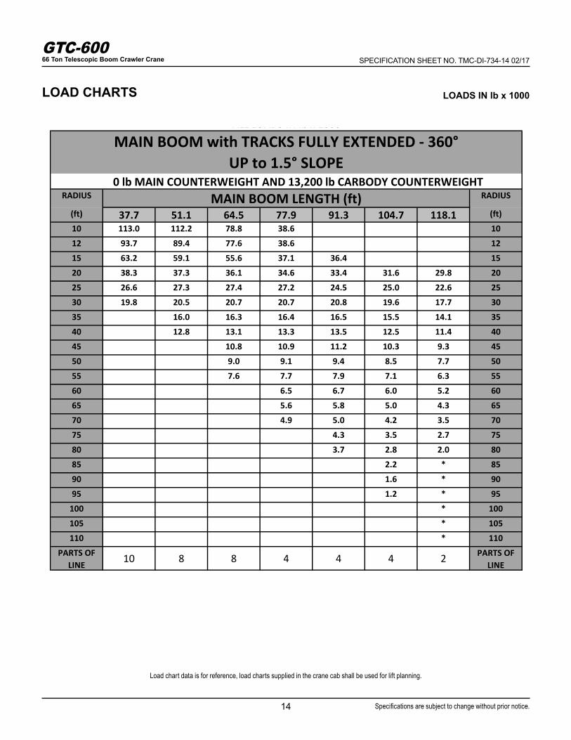
RADIUS RADIUS
(ft) 37.7 51.1 64.5 77.9 91.3 104.7 118.1 (ft)10 113.0 112.2 78.8 38.6 1012 93.7 89.4 77.6 38.6 1215 63.2 59.1 55.6 37.1 36.4 1520 38.3 37.3 36.1 34.6 33.4 31.6 29.8 2025 26.6 27.3 27.4 27.2 24.5 25.0 22.6 2530 19.8 20.5 20.7 20.7 20.8 19.6 17.7 3035 16.0 16.3 16.4 16.5 15.5 14.1 3540 12.8 13.1 13.3 13.5 12.5 11.4 4045 10.8 10.9 11.2 10.3 9.3 4550 9.0 9.1 9.4 8.5 7.7 5055 7.6 7.7 7.9 7.1 6.3 5560 6.5 6.7 6.0 5.2 6065 5.6 5.8 5.0 4.3 6570 4.9 5.0 4.2 3.5 7075 4.3 3.5 2.7 7580 3.7 2.8 2.0 8085 2.2 * 8590 1.6 * 9095 1.2 * 95100 * 100105 * 105110 * 110
PARTS OF LINE
10 8 8 4 4 4 2 PARTS OF LINE
MAIN BOOM with TRACKS FULLY EXTENDED ‐ 360°UP to 1.5° SLOPE
0 lb MAIN COUNTERWEIGHT AND 13,200 lb CARBODY COUNTERWEIGHTMAIN BOOM LENGTH (ft)
ALL LOADS IN lb x 1000

LOAD CHARTS LOADS IN lb x 1000
15
GTC-60066 Ton Telescopic Boom Crawler Crane SPECIFICATION SHEET NO. TMC-DI-734-14 02/17
Specifications are subject to change without prior notice.
Load chart data is for reference, load charts supplied in the crane cab shall be used for lift planning.
RADIUS RADIUS
(ft) 37.7 51.1 64.5 77.9 91.3 104.7 118.1 (ft)10 14.6 14.6 14.6 1012 14.6 14.6 14.6 14.6 1215 14.6 14.6 14.6 14.6 14.6 1520 14.6 14.6 14.6 14.6 14.6 14.6 2025 14.6 14.6 14.6 14.6 14.6 14.6 14.6 2530 14.6 14.6 14.6 14.6 14.6 14.6 14.6 3035 14.6 14.6 14.6 14.6 14.6 14.6 3540 14.6 14.6 14.6 14.6 14.6 14.6 4045 14.6 14.6 14.6 14.6 14.6 14.6 4550 14.6 14.6 14.6 14.6 14.6 5055 14.6 14.6 14.6 14.6 14.6 5560 14.6 14.6 13.0 13.3 13.5 6065 13.3 11.4 11.9 11.9 6570 11.9 10.0 11.1 10.5 7075 9.1 10.0 9.3 7580 8.5 9.0 8.4 8085 8.0 8.1 7.5 8590 7.3 6.7 9095 6.6 6.0 95100 6.1 5.4 100105 4.8 105110 4.3 110
PARTS OF LINE
1 1 1 1 1 1 1 PARTS OF LINE
AUX NOSE SHEAVE with TRACKS FULLY EXTENDED ‐ 360°UP to 1.5° SLOPE
30,000 lb MAIN COUNTERWEIGHT AND 13,200 lb CARBODY COUNTERWEIGHTMAIN BOOM LENGTH (ft)
ALL LOADS IN lb x 1000

LOAD CHARTS LOADS IN lb x 1000
16
GTC-60066 Ton Telescopic Boom Crawler Crane SPECIFICATION SHEET NO. TMC-DI-734-14 02/17
Specifications are subject to change without prior notice.
Load chart data is for reference, load charts supplied in the crane cab shall be used for lift planning.
RADIUS RADIUS
3.5° 30° 3.5° 30° 3.5° 30° 3.5° 30° 3.5° 30°10 44.8 35.1 10
12 43.1 34.2 12
15 40.9 33.2 33.3 32.6 15
20 37.9 31.9 27.3 26.9 24.2 26.2 28.2 20
25 35.7 31.2 27.0 26.6 23.1 22.5 24.5 23.6 25.3 24.2 25
30 34.3 31.2 26.7 26.3 20.1 19.7 21.5 20.9 22.5 21.6 30
35 31.2 31.2 26.3 25.6 17.7 17.4 19.1 18.6 20.2 19.5 35
40 23.9 23.4 15.7 15.5 17.2 16.8 18.2 17.7 40
45 21.7 21.5 14.1 14.0 15.5 15.2 16.6 16.2 45
50 18.7 18.9 12.7 12.7 14.1 13.9 15.2 14.8 50
55 16.2 16.4 11.6 11.5 12.9 12.7 14.0 13.7 55
60 14.2 14.4 10.6 10.5 11.8 11.7 12.7 12.7 60
65 12.6 12.7 9.7 9.7 10.9 10.8 11.0 11.3 65
70 11.2 11.3 8.9 8.9 10.1 10.1 9.7 9.9 70
75 10.1 8.3 8.3 9.2 9.3 8.5 8.7 75
80 7.7 7.7 8.2 8.3 7.5 7.7 80
85 7.1 7.3 7.4 6.7 6.8 85
90 6.7 6.5 6.6 5.9 6.0 90
95 5.8 5.2 5.2 95
100 5.2 4.6 4.6 100
105 4.7 4.0 4.1 105
110 3.4 110
115 2.9 115
PARTS OF LINE 4 4 2 2 2 2 2 2 2 2 PARTS OF
LINE
(ft) (ft)37.7 77.9 91.3 104.7 118.1
ALL LOADS IN lb x 1000
8.2FT JIB with TRACKS FULLY EXTENDED ‐ 360°UP to 1.5° SLOPE
30,000 lb MAIN COUNTERWEIGHT AND 13,200 lb CARBODY COUNTERWEIGHTMAIN BOOM LENGTH (ft)
LOAD CHARTS LOADS IN lb x 1000
17
GTC-60066 Ton Telescopic Boom Crawler Crane SPECIFICATION SHEET NO. TMC-DI-734-14 02/17
Specifications are subject to change without prior notice.
Load chart data is for reference, load charts supplied in the crane cab shall be used for lift planning.
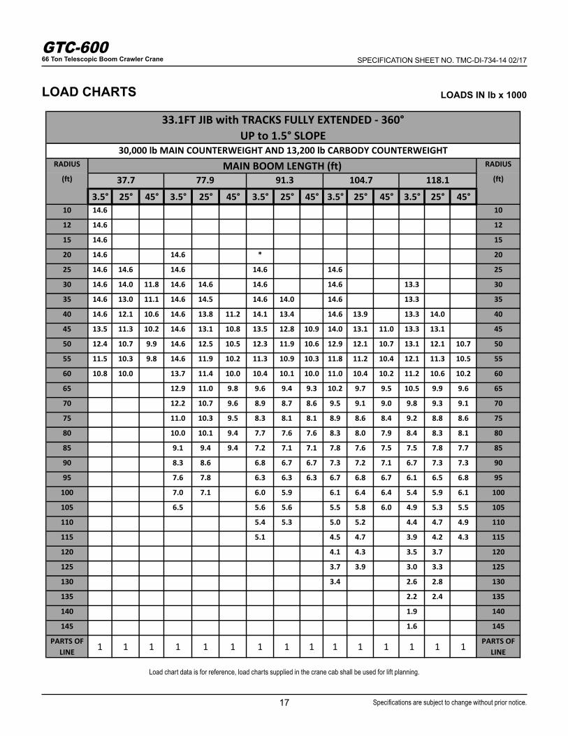
RADIUS RADIUS
3.5° 25° 45° 3.5° 25° 45° 3.5° 25° 45° 3.5° 25° 45° 3.5° 25° 45°10 14.6 10
12 14.6 12
15 14.6 15
20 14.6 14.6 * 20
25 14.6 14.6 14.6 14.6 14.6 25
30 14.6 14.0 11.8 14.6 14.6 14.6 14.6 13.3 30
35 14.6 13.0 11.1 14.6 14.5 14.6 14.0 14.6 13.3 35
40 14.6 12.1 10.6 14.6 13.8 11.2 14.1 13.4 14.6 13.9 13.3 14.0 40
45 13.5 11.3 10.2 14.6 13.1 10.8 13.5 12.8 10.9 14.0 13.1 11.0 13.3 13.1 45
50 12.4 10.7 9.9 14.6 12.5 10.5 12.3 11.9 10.6 12.9 12.1 10.7 13.1 12.1 10.7 50
55 11.5 10.3 9.8 14.6 11.9 10.2 11.3 10.9 10.3 11.8 11.2 10.4 12.1 11.3 10.5 55
60 10.8 10.0 13.7 11.4 10.0 10.4 10.1 10.0 11.0 10.4 10.2 11.2 10.6 10.2 60
65 12.9 11.0 9.8 9.6 9.4 9.3 10.2 9.7 9.5 10.5 9.9 9.6 65
70 12.2 10.7 9.6 8.9 8.7 8.6 9.5 9.1 9.0 9.8 9.3 9.1 70
75 11.0 10.3 9.5 8.3 8.1 8.1 8.9 8.6 8.4 9.2 8.8 8.6 75
80 10.0 10.1 9.4 7.7 7.6 7.6 8.3 8.0 7.9 8.4 8.3 8.1 80
85 9.1 9.4 9.4 7.2 7.1 7.1 7.8 7.6 7.5 7.5 7.8 7.7 85
90 8.3 8.6 6.8 6.7 6.7 7.3 7.2 7.1 6.7 7.3 7.3 90
95 7.6 7.8 6.3 6.3 6.3 6.7 6.8 6.7 6.1 6.5 6.8 95
100 7.0 7.1 6.0 5.9 6.1 6.4 6.4 5.4 5.9 6.1 100
105 6.5 5.6 5.6 5.5 5.8 6.0 4.9 5.3 5.5 105
110 5.4 5.3 5.0 5.2 4.4 4.7 4.9 110
115 5.1 4.5 4.7 3.9 4.2 4.3 115
120 4.1 4.3 3.5 3.7 120
125 3.7 3.9 3.0 3.3 125
130 3.4 2.6 2.8 130
135 2.2 2.4 135
140 1.9 140
145 1.6 145
PARTS OF LINE 1 1 1 1 1 1 1 1 1 1 1 1 1 1 1 PARTS OF
LINE
ALL LOADS IN lb x 1000
(ft) (ft)37.7 77.9 91.3 104.7 118.1
33.1FT JIB with TRACKS FULLY EXTENDED ‐ 360°UP to 1.5° SLOPE
30,000 lb MAIN COUNTERWEIGHT AND 13,200 lb CARBODY COUNTERWEIGHTMAIN BOOM LENGTH (ft)

LOAD CHARTS LOADS IN lb x 1000
18
GTC-60066 Ton Telescopic Boom Crawler Crane SPECIFICATION SHEET NO. TMC-DI-734-14 02/17
Specifications are subject to change without prior notice.
Load chart data is for reference, load charts supplied in the crane cab shall be used for lift planning.
RADIUS RADIUS
3.5° 25° 45° 3.5° 25° 45° 3.5° 25° 45° 3.5° 25° 45° 3.5° 25° 45°10 10
12 12
15 15
20 9.8 20
25 9.8 * 25
30 9.8 8.1 7.6 * 30
35 9.6 8.1 7.6 7.3 * 35
40 8.8 7.9 8.1 7.6 7.3 7.0 40
45 8.0 7.5 8.1 7.9 7.6 7.3 7.0 45
50 7.4 7.0 6.0 8.1 7.5 7.6 7.6 7.3 7.0 50
55 6.9 6.6 5.6 8.1 7.2 7.6 7.3 7.3 7.3 7.0 * 55
60 6.4 6.1 5.4 7.8 6.9 5.6 7.6 7.0 7.3 7.1 7.0 7.0 60
65 6.0 5.7 5.1 7.4 6.6 5.4 7.6 6.8 5.5 7.3 6.9 7.0 6.9 65
70 5.7 5.4 4.9 7.0 6.3 5.2 7.3 6.5 5.3 7.3 6.6 5.3 7.0 6.7 * 70
75 5.4 5.1 4.7 6.7 6.0 5.1 6.9 6.2 5.1 7.1 6.4 5.2 7.0 6.5 5.2 75
80 5.1 4.8 4.6 6.4 5.8 4.9 6.6 5.9 5.0 6.9 6.1 5.0 7.0 6.2 5.1 80
85 4.9 4.6 6.1 5.5 4.8 6.3 5.7 4.9 6.6 5.9 4.9 6.7 6.0 5.0 85
90 5.9 5.3 4.7 5.9 5.5 4.7 6.3 5.6 4.8 6.5 5.8 4.8 90
95 5.6 5.1 4.6 5.5 5.3 4.6 5.9 5.4 4.7 6.2 5.6 4.7 95
100 5.4 4.9 4.5 5.2 5.1 4.5 5.6 5.3 4.6 5.8 5.4 4.6 100
105 5.2 4.8 4.4 4.9 4.9 4.5 5.2 5.1 4.5 5.3 5.2 4.5 105
110 5.1 4.6 4.4 4.6 4.6 4.4 5.0 4.9 4.4 4.8 5.0 4.5 110
115 4.9 4.5 4.3 4.3 4.3 4.7 4.6 4.4 4.3 4.8 4.4 115
120 4.8 4.4 4.1 4.1 4.1 4.5 4.4 4.3 3.9 4.5 4.3 120
125 4.7 4.4 3.9 3.9 4.1 4.2 4.2 3.5 4.0 4.3 125
130 3.7 3.7 3.7 4.0 4.0 3.1 3.6 3.9 130
135 3.5 3.5 3.4 3.7 2.7 3.2 3.4 135
140 3.3 3.1 3.4 2.3 2.8 140
145 2.8 3.0 2.0 2.4 145
150 2.5 2.6 1.7 2.0 150
155 2.2 1.4 1.7 155
PARTS OF LINE 1 1 1 1 1 1 1 1 1 1 1 1 1 1 1 PARTS OF
LINE
ALL LOADS IN lb x 1000
37.7 77.9 91.3 104.7 118.1
58.1FT JIB with TRACKS FULLY EXTENDED ‐ 360°UP to 1.5° SLOPE
30,000 lb MAIN COUNTERWEIGHT AND 13,200 lb CARBODY COUNTERWEIGHTMAIN BOOM LENGTH (ft)
(ft) (ft)
19
GTC-60066 Ton Telescopic Boom Crawler Crane SPECIFICATION SHEET NO. TMC-DI-734-14 02/17
Specifications are subject to change without prior notice.
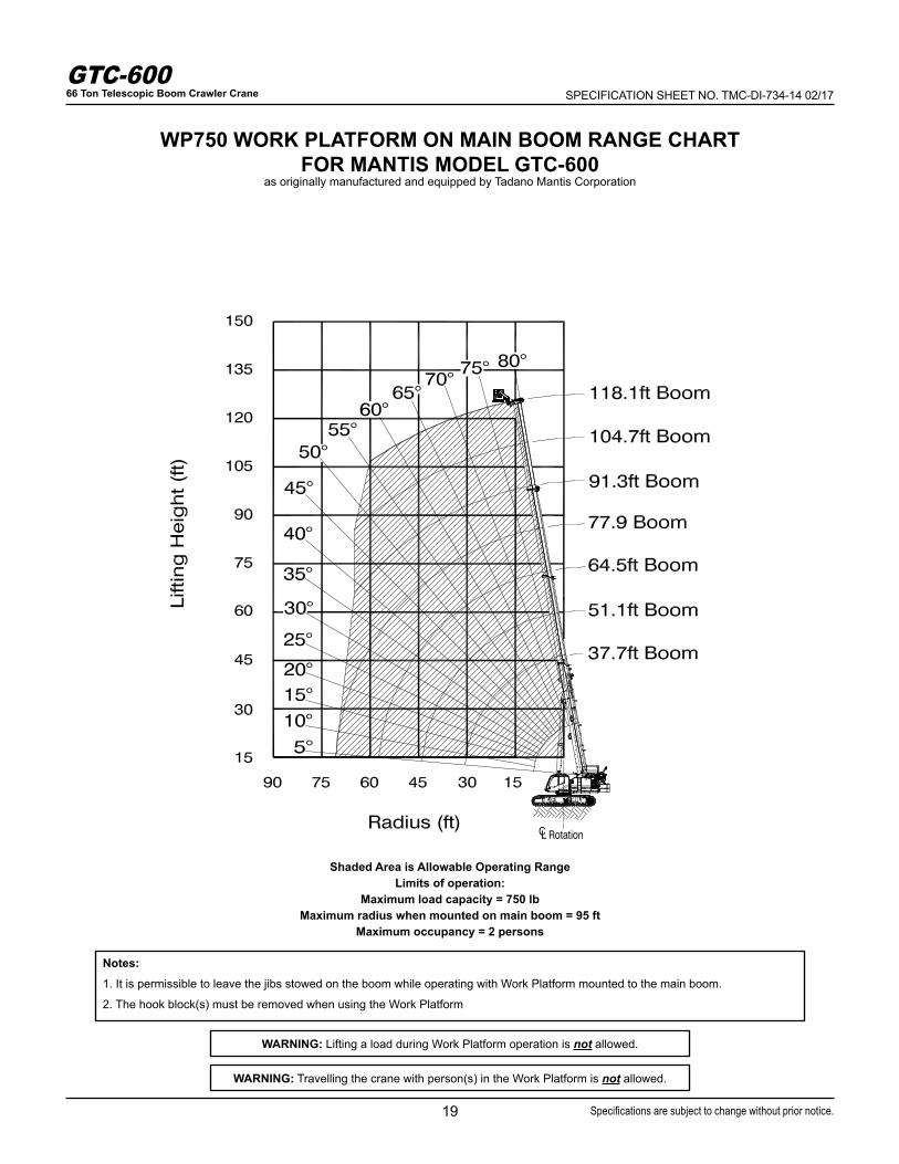
WP750 WORK PLATFORM ON MAIN BOOM RANGE CHARTFOR MANTIS MODEL GTC-600
as originally manufactured and equipped by Tadano Mantis Corporation
Shaded Area is Allowable Operating RangeLimits of operation:
Maximum load capacity = 750 lbMaximum radius when mounted on main boom = 95 ft
Maximum occupancy = 2 persons
WARNING: Travelling the crane with person(s) in the Work Platform is not allowed.
WARNING: Lifting a load during Work Platform operation is not allowed.
Notes:
1. It is permissible to leave the jibs stowed on the boom while operating with Work Platform mounted to the main boom.
2. The hook block(s) must be removed when using the Work Platform

20
GTC-60066 Ton Telescopic Boom Crawler Crane SPECIFICATION SHEET NO. TMC-DI-734-14 02/17
Specifications are subject to change without prior notice.
WP750 WORK PLATFORM ON 33.5 FT (10.2 M) EXTENSION RANGE CHARTFOR MANTIS MODEL GTC-600
as originally manufactured and equipped by Tadano Mantis Corporation
Shaded Area is Allowable Operating RangeLimits of operation:
Minimum boom angle when mounted on 33.5ft (10.2m) extension at 0° offset = 0°Minimum boom angle when mounted on 33.5ft (10.2m) extension at 20°offset = 20°Minimum boom angle when mounted on 33.5ft (10.2m) extension at 40°offset = 40°
Maximum occupancy = 2 persons
WARNING: Travelling the crane with person(s) in the Work Platform is not allowed.
WARNING: Lifting a load during Work Platform operation is not allowed.
Notes:
1. It is permissible to leave the jib section stowed on the boom while operating with Work Platform mounted to the 33.5 ft (10.2m) jib.
2. The hook block(s) must be removed when using the Work Platform
21
GTC-60066 Ton Telescopic Boom Crawler Crane SPECIFICATION SHEET NO. TMC-DI-734-14 02/17
Specifications are subject to change without prior notice.
PLEASE READ, UNDERSTAND, AND FOLLOW THE MANUALS FURNISHED WITH THE CRANE AS WELL AS THE CAPACITY LIMITA-TIONS AND GENERAL CONDITIONS LISTED BELOW PRIOR TO OPERATI ON OF THE CRANE. FAILURE TO DO SO MAY RESULT IN AN ACCIDENT.
Performance of this TADANO MANTIS crane as manufactured by Tadano Mantis Corporation applies only to machines as originally equipped by the manufacturer and in a properly maintained condition. Capacities given are maximum covered by the manufacturer’s warranty and are based on a freely suspended load with NO allowance for factors as out-of-level operation (beyond the limits specified on the charts), supporting surface conditions, hazardous surroundings, experience of personnel, etc. The operator shall establish practical working loads based on prevail-ing operating conditions, such as, but not limited to the above.
The crane meets the requirements of ASME B30.5. Structure and Stability have been tested in accordance with SAE J1063 and SAE J765, respectively.
Maximum admissible wind velocity for working with telescopic boom and jibs is 20 mph. Consult TADANO MANTIS for ratings at higher wind speeds.
Side pull on boom is extremely dangerous and must be avoided.
DO NOT exceed manufacturers maximum specified reeving.Boom angle/boom length relationships given are an approximation of the resulted load radius, which should be an accurate measurement. Boom height dimensions are measured from ground to center of lower boom head sheave.
It is permissible to attempt to telescope boom with a load within the limits of rated capacities. However, boom angle system hydraulic pressure, and/or boom lubrication may affect operation.
It is permissible to travel with loads within the rated capacity of the crane. Travel speeds should be greatly reduced to reflect terrain limitations and minimize dynamic loads applied to the crane structure.
Lifting capacities are shown in lbs x 1000.
The weight of load handling devices such as hook blocks, slings, etc., must be considered as part of the load and must be deducted from the lifting capacities.
The lifting capacities for the telescopic boom apply to a crane with no jibs or other optional equipment stowed or mounted on the crane.
The working radius is the horizontal distance from the center of rotation to the center of the freely suspended, non-oscillating load.
The lifting capacities are subject to change without prior notice.
The above remarks are for basic information only and the operator’s manual must be consulted before operating this crane. All data and perfor-mances refer to the standard crane. The addition of optional and other non-standard equipment may affect the performance of the crane.
Load moment indicating and anti-two block systems are operator aids and must never be used in lieu of job site lift planning calculations by the operator which must take into account ground conditions, weather and all other environmental factors prevailing at the time of the lift. Speci-fications are subject to change at any time without prior notice. Illustrations and photographs may show optional equipment. Supersedes all previous issues.
NOTES
22
GTC-60066 Ton Telescopic Boom Crawler Crane SPECIFICATION SHEET NO. TMC-DI-734-14 02/17
Specifications are subject to change without prior notice.

NOTES
23
GTC-60066 Ton Telescopic Boom Crawler Crane SPECIFICATION SHEET NO. TMC-DI-734-14 02/17
Specifications are subject to change without prior notice.

TADA
NO M
ANTI
S COR
PORA
TION
1705
Colu
mbi
a Ave
nue •
Fran
klin
, TN
3706
4 US
A • T
oll-F
ree:
1-80
0-27
2-33
25 •
Fax:
615-
790-
6803
• m
antis
cran
es.co
m
SPECIFICATION SHEET NO. TMC-DI-734-14 02/17
TADANO Ltd.,International Division4-12, Kamezawa 2-chome,Sumida-Ku, Tokyo 130-0014, JapanTel: +81 3 3621 7750Fax: +81 3 3621 7785E-mail: [email protected]