grundfos data booklet - · pdf fileto remove the pump head from the pump housing, use a lever...
TRANSCRIPT
GRUNDFOS DATA BOOKLET
MTB
Centrifugal machine tool pumps50 Hz
2
Contents
General descriptionIntroduction 3Applications 3Special features 3
IdentificationType key 4Codes 4Pump types and data 4
ConstructionSectional drawings 5Material specification 5Mechanical construction 6Surface treatment 6Test pressure 6Motor 6
Operating conditionsInlet pressure 7Maximum operating pressure 7Ambient temperature 7
InstallationPositioning 8Vertical installation 8Horizontal installation 8Pipework 8Foundation 8Elimination of noise and vibration 9
Selection of productPump size 10Efficiency 10Shaft seal material 10
Pumped liquidsPumped liquids 11List of pumped liquids 11
Curve chartsHow to read the curve charts 13Curve conditions 13Calculation of total head 13
Performance curves/Technical dataMTB 65-160, 2-pole 14MTB 65-200, 2-pole 16MTB 50-200, 4-pole 18
AccessoriesSupport blocks 20
ServiceSpare parts 21
Further product documentationWebCAPS 22WinCAPS 23
3
MTBGeneral description
IntroductionThe MTB machine tool pumps are single-stage centrifugal pumps with axial suction port and radial discharge port.
The unique SuperVortex impeller is capable of handling solids and swarf up to 20 mm.
The pump is directly coupled to a totally enclosed fan-cooled standard motor. Main dimensions are according to IEC and DIN standards.
ApplicationsThe MTB pumps are designed specifically for industrial machine tool and cleaning applications such as
• machining centres• cooling systems• grinding machines• lathes• parts-cleaning systems.
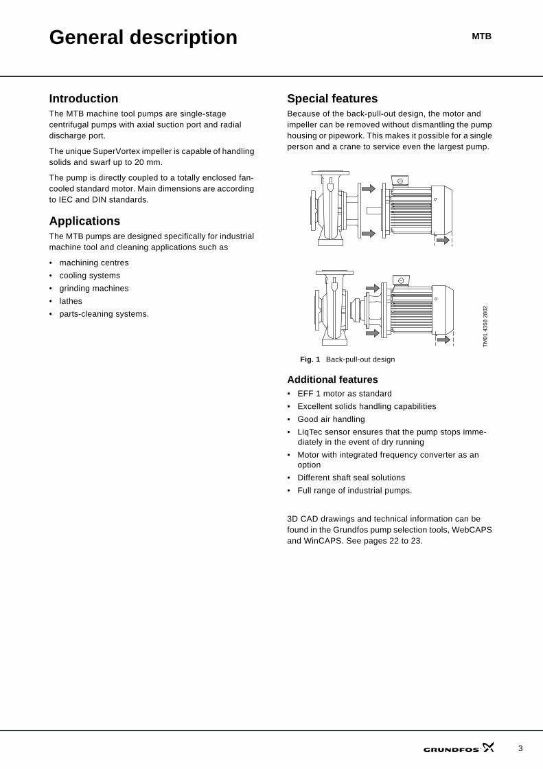
Special featuresBecause of the back-pull-out design, the motor and impeller can be removed without dismantling the pump housing or pipework. This makes it possible for a single person and a crane to service even the largest pump.
Fig. 1 Back-pull-out design
Additional features• EFF 1 motor as standard• Excellent solids handling capabilities• Good air handling• LiqTec sensor ensures that the pump stops imme-
diately in the event of dry running • Motor with integrated frequency converter as an
option• Different shaft seal solutions• Full range of industrial pumps.
3D CAD drawings and technical information can be found in the Grundfos pump selection tools, WebCAPS and WinCAPS. See pages 22 to 23.
TM01
435
8 28
02
MTB
4
Identification
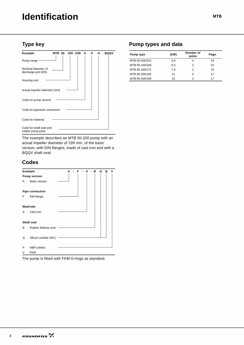
Type key
The example describes an MTB 50-200 pump with an actual impeller diameter of 199 mm, of the basic version, with DIN flanges, made of cast iron and with a BQQV shaft seal.
Codes
The pump is fitted with FKM O-rings as standard.
Pump types and dataExample MTB 65 -200 /199 A -F -A -BQQV
Pump range
Nominal diameter of discharge port (DN)
Housing size
Actual impeller diameter [mm]
Code for pump version
Code for pipework connection
Code for material
Code for shaft seal and rubber pump parts
Example A - F - A - B Q Q VPump versionA Basic version
Pipe connection
F DIN flange
Materials
A Cast iron
Shaft seal
B Rubber bellows seal
Q Silicon carbide (SiC)
P NBR (nitrile)
V FKM
Pump type [kW] Number of poles Page
MTB 50-200/215 3.0 4 19MTB 65-160/158 5.5 2 15MTB 65-160/171 7.5 2 15MTB 65-200/183 11 2 17MTB 65-200/199 15 2 17
MTBConstruction
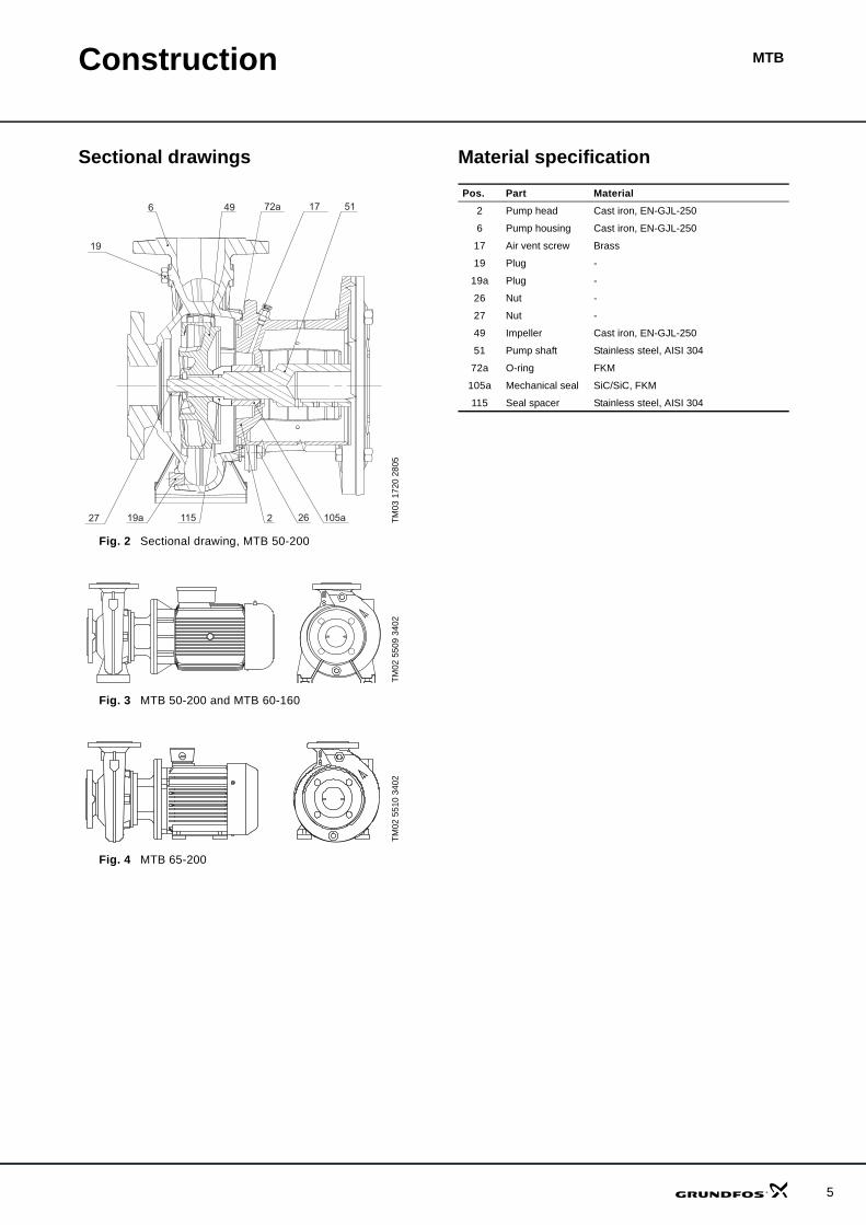
Sectional drawings
Fig. 2 Sectional drawing, MTB 50-200
Fig. 3 MTB 50-200 and MTB 60-160
Fig. 4 MTB 65-200
Material specification
TM03
172
0 28
05TM
02 5
509
3402
TM02
551
0 34
02
19
6 49 72a 17 51
19a 115 2 26 105a27
Pos. Part Material2 Pump head Cast iron, EN-GJL-250
6 Pump housing Cast iron, EN-GJL-250
17 Air vent screw Brass
19 Plug -
19a Plug -
26 Nut -
27 Nut -
49 Impeller Cast iron, EN-GJL-250
51 Pump shaft Stainless steel, AISI 304
72a O-ring FKM
105a Mechanical seal SiC/SiC, FKM
115 Seal spacer Stainless steel, AISI 304
5

6
Construction MTB
Mechanical construction
Pump housingVolute pump housing made of cast iron with axial suction port and radial discharge port. Flange connec-tion dimensions are in accordance with EN 1092-2.
The bottom of the pump housing incorporates a drain plug.
The discharge port has a pressure gauge tapping.
Pump headCombining pump housing and motor, the pump head is provided with a manual air vent screw for the venting of pump housing and seal chamber. An O-ring provides a seal between pump head and pump housing.
Coupling guards are fitted in the central part of the pump head.
To remove the pump head from the pump housing, use a lever between the pump housing and the pump head.
MTB pumps are fitted with the following motor flange types:
• type IM B 5 for motor sizes up to MMG 132 (according to IEC 60034)
• type IM B 35 for motor size MMG 160 (according to IEC 60034).
ShaftStainless steel shaft of ø28 or ø38 mm.
The coupling end of the shaft is cylindrical and has two drilled holes for the shaft pin of the coupling.
Shaft sealMTB pumps are fitted with an unbalanced, mechanical SiC/SiC shaft seal with FKM as standard material. NBR material is available on request.
A brief liquid circulation during start-up, by manually opening the air vent screw in the pump head, ensures perfect lubrication and cooling of the shaft seal.
Maximum operating temperature and pressure
CouplingMTB pumps are fitted with a cylindrical, hollow steel coupling secured by two hexagon socket head screws.
ImpellerThe semi-open impeller is made of cast iron.
All MTB pumps are dynamically balanced. The impeller is hydraulically balanced to compensate for axial thrust.
The impeller is extremely suitable for handling swarf and solids.
Spherical impeller clearance: Max. 20 mm.
Note: When viewed from the motor fan, the impeller rotates clockwise.
Surface treatmentAll stationary cast iron parts are dip-painted with water-based ether-epoxy no-lead painting. Thickness: 25 μm ± 5 μm.
In addition, the product is spray-painted with black water-based ether-epoxy no-lead painting (NCS 9000/RAL 9005). Thickness: 35 μm ± 5 μm.
Test pressureBefore delivery, the pumps have been tested at 1.5 times maximum operating pressure.
Test requirements according to EN 733 are 1.3 times maximum operating pressure.
Test liquid: Water, 20°C.
MotorMTB pumps are equipped with a totally enclosed, fan-cooled, EFF 1 motor with main dimensions to IEC and DIN standards.
Motor data
The motor must be connected to a motor starter in accordance with local regulations.
Shaft seal Operating temperature
Maximum operating pressure [bar]
BQQV 0°C to +90°C 16 barBQQP 0°C to +90°C 16 bar
EFF 1 motor rangeOutputP2 [kW] 2-pole 4-pole
3.0 MG model D5.5
MG model C7.511.0
MMG model E15.0
Flange typesType IM B 5 for motor sizes up to MMG 132, according to IEC 60034Type IM B 35 for motor size MMG 160, according to IEC 60034
Insulation class F, according to IEC 85Electrical tolerances According to VDE 0530
Efficiency class EFF 1: MG and MMG model DEnclosure class IP 5550 Hz standard voltages
3 x 380-415Δ/660-690Y V, 50 Hz3 x 220-240Y/380-415Δ V, 50 Hz3 x 380-415Δ V, 50 Hz
7
MTBOperating conditions
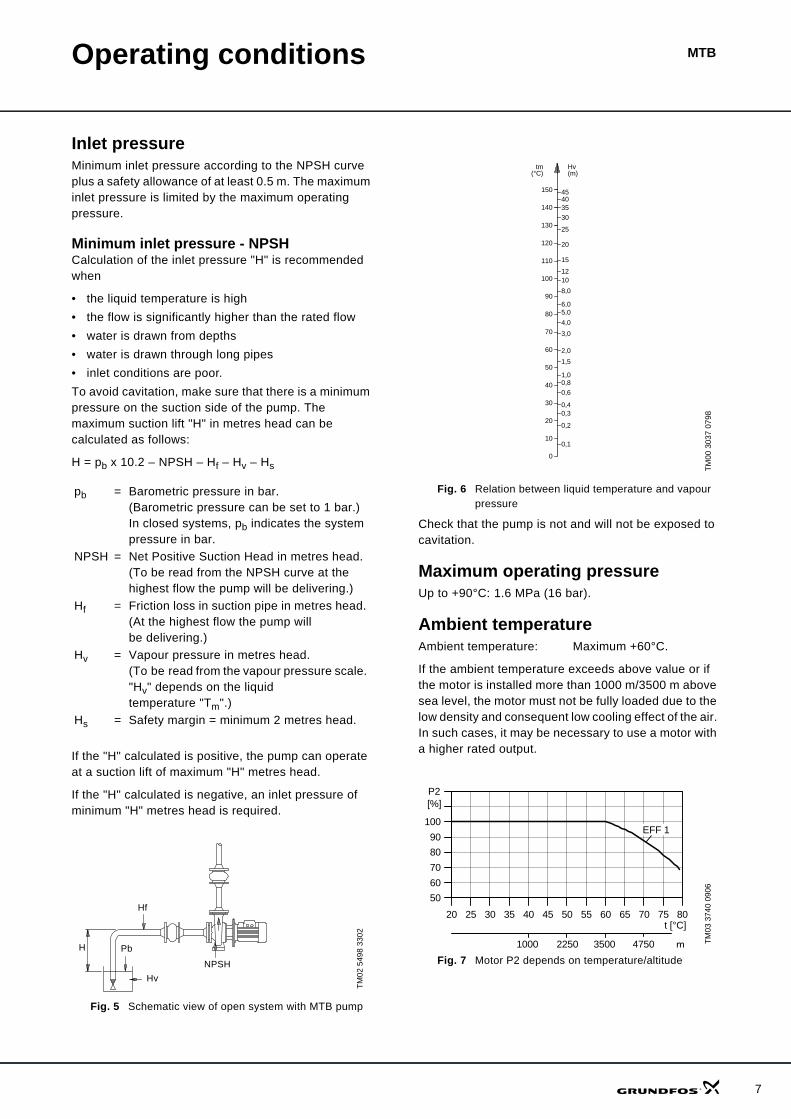
Inlet pressureMinimum inlet pressure according to the NPSH curve plus a safety allowance of at least 0.5 m. The maximum inlet pressure is limited by the maximum operating pressure.
Minimum inlet pressure - NPSHCalculation of the inlet pressure "H" is recommended when
• the liquid temperature is high• the flow is significantly higher than the rated flow• water is drawn from depths• water is drawn through long pipes• inlet conditions are poor.To avoid cavitation, make sure that there is a minimum pressure on the suction side of the pump. The maximum suction lift "H" in metres head can be calculated as follows:
H = pb x 10.2 – NPSH – Hf – Hv – Hs
If the "H" calculated is positive, the pump can operate at a suction lift of maximum "H" metres head.
If the "H" calculated is negative, an inlet pressure of minimum "H" metres head is required.
Fig. 5 Schematic view of open system with MTB pump
Fig. 6 Relation between liquid temperature and vapour pressure
Check that the pump is not and will not be exposed to cavitation.
Maximum operating pressureUp to +90°C: 1.6 MPa (16 bar).
Ambient temperatureAmbient temperature: Maximum +60°C.
If the ambient temperature exceeds above value or if the motor is installed more than 1000 m/3500 m above sea level, the motor must not be fully loaded due to the low density and consequent low cooling effect of the air. In such cases, it may be necessary to use a motor with a higher rated output.
Fig. 7 Motor P2 depends on temperature/altitude
pb = Barometric pressure in bar. (Barometric pressure can be set to 1 bar.) In closed systems, pb indicates the system pressure in bar.
NPSH = Net Positive Suction Head in metres head. (To be read from the NPSH curve at the highest flow the pump will be delivering.)
Hf = Friction loss in suction pipe in metres head. (At the highest flow the pump will be delivering.)
Hv = Vapour pressure in metres head. (To be read from the vapour pressure scale. "Hv" depends on the liquid temperature "Tm".)
Hs = Safety margin = minimum 2 metres head.
TM02
549
8 33
02
H Pb
HvNPSH
Hf
TM00
303
7 07
98TM
03 3
740
0906
20
15
1210
8,0
6,05,0
4,0
3,0
2,0
1,00,8
0,6
0,40,3
0,2
0,1
1,5
120
110
90
100
80
70
60
50
40
30
20
10
0
Hv(m)
tm(°C)
150
130
140
25
35
4540
30
20 25 30 35 40 45 50 55 60 65 70 75 80
50
60
70
80
90
100
[%]P2
EFF 1
t [°C]
1000 2250 3500 4750 m
8
MTBInstallation
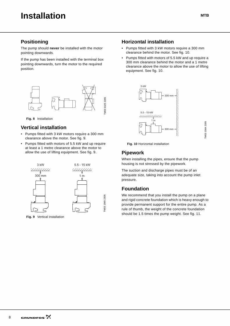
PositioningThe pump should never be installed with the motor pointing downwards.
If the pump has been installed with the terminal box pointing downwards, turn the motor to the required position.
Fig. 8 Installation
Vertical installation• Pumps fitted with 3 kW motors require a 300 mm
clearance above the motor. See fig. 9.• Pumps fitted with motors of 5.5 kW and up require
at least a 1 metre clearance above the motor to allow the use of lifting equipment. See fig. 9.
Fig. 9 Vertical installation
Horizontal installation• Pumps fitted with 3 kW motors require a 300 mm
clearance behind the motor. See fig. 10.• Pumps fitted with motors of 5.5 kW and up require a
300 mm clearance behind the motor and a 1 metre clearance above the motor to allow the use of lifting equipment. See fig. 10.
Fig. 10 Horizontal installation
PipeworkWhen installing the pipes, ensure that the pump housing is not stressed by the pipework.
The suction and discharge pipes must be of an adequate size, taking into account the pump inlet pressure.
FoundationWe recommend that you install the pump on a plane and rigid concrete foundation which is heavy enough to provide permanent support for the entire pump. As a rule of thumb, the weight of the concrete foundation should be 1.5 times the pump weight. See fig. 11.
TM00
632
5 33
95TM
03 1
565
2305
3 kW 5.5 - 15 kW
300 mm 1 m
TM03
156
4 23
05
5.5 - 15 kW
300 mm
300 mm
1 m
3 kW
Installation MTB
Elimination of noise and vibrationIn order to achieve optimum operation and minimum noise and vibration, consider vibration dampening of the pump. Generally, always consider this for pumps with motors above 7.5 kW. Smaller motor sizes, however, may also cause undesirable noise and vibra-tion.
Noise and vibration are generated by the revolutions of the motor and pump and by the flow in pipes and fittings. The effect on the environment is subjective and depends on correct installation and the state of the remaining system.
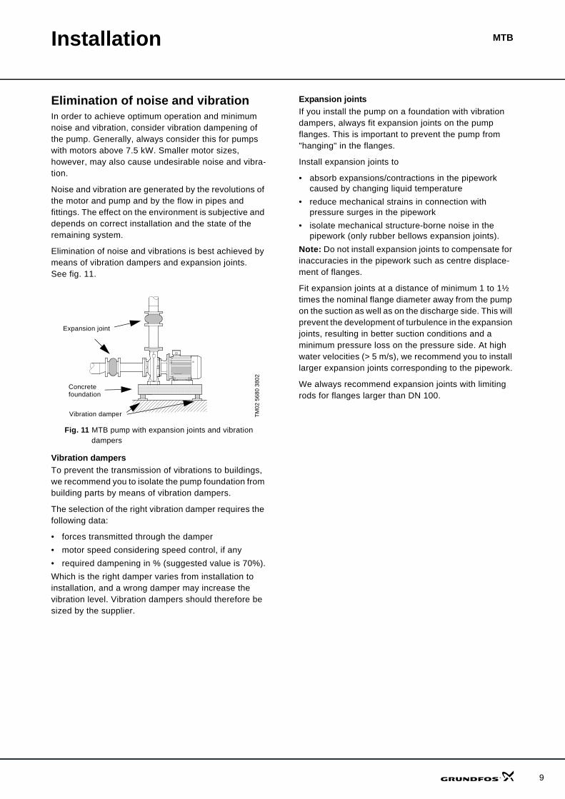
Elimination of noise and vibrations is best achieved by means of vibration dampers and expansion joints. See fig. 11.
Fig. 11 MTB pump with expansion joints and vibration dampers
Vibration dampersTo prevent the transmission of vibrations to buildings, we recommend you to isolate the pump foundation from building parts by means of vibration dampers.
The selection of the right vibration damper requires the following data:
• forces transmitted through the damper• motor speed considering speed control, if any• required dampening in % (suggested value is 70%).Which is the right damper varies from installation to installation, and a wrong damper may increase the vibration level. Vibration dampers should therefore be sized by the supplier.
Expansion jointsIf you install the pump on a foundation with vibration dampers, always fit expansion joints on the pump flanges. This is important to prevent the pump from "hanging" in the flanges.
Install expansion joints to
• absorb expansions/contractions in the pipework caused by changing liquid temperature
• reduce mechanical strains in connection with pressure surges in the pipework
• isolate mechanical structure-borne noise in the pipework (only rubber bellows expansion joints).
Note: Do not install expansion joints to compensate for inaccuracies in the pipework such as centre displace-ment of flanges.
Fit expansion joints at a distance of minimum 1 to 1½ times the nominal flange diameter away from the pump on the suction as well as on the discharge side. This will prevent the development of turbulence in the expansion joints, resulting in better suction conditions and a minimum pressure loss on the pressure side. At high water velocities (> 5 m/s), we recommend you to install larger expansion joints corresponding to the pipework.
We always recommend expansion joints with limiting rods for flanges larger than DN 100.
TM02
568
0 38
02
•• •• •• •• •• •• •• •• •• •• •• •• •• •• •• •• •• ••• •• •• •• •• •• •• •• •• •• •• •• •• •• •• •• •• ••• •• •• •• •• •• •• •• •• •• •• •• •• •• •• •• •• ••• •• •• •• •• •• •• •• •• •• •• •• •• •• •• •• •• ••• •• •• •• •• •• •• •• •• •• •• •• •• •• •• •• •• ••• •• •• •• •• •• •• •• •• •• •• •• •• •• •• •• •• ••• •• •• •• •• •• •• •• •• •• •• •• •• •• •• •• •• ••• •• •• •• •• •• •• •• •
• •• •• •• •• •• •• •• •• ••• •• •• •• •• •• •• •• •• •• •• •• •• •• •• •• •• ••• •• •• •• •• •• •• •• •• •• •• •• •• •• •• •• •• ••• •• •• •• •• •• •• •• •• •• •• •• •• •• •• •• •• ••• •• •• •• •• •• •• •• •• •• •• •• •• •• •• •• •• ••• •• •• •• •• •• •• •• •• •• •• •• •• •• •• •• •• ••• •• •• •• •• •• •• •• •• •• •• •• •• •• •• •• •• ••• •• •• •• •• •• •• •• •• •• •• •• •• •• •• •• •• •• • • • • • • • • • • • • • • • • • • • • • • • • • • • • • • • • • • • • • • • • • • • • • • • • • • • • • • • • • • • • • • • • • • • • • • • • • • • • • • • • • • • • • • • • • • • • • • • • • • • • • • • • • • • • • • • • • • • • • • • • • • • • • • • • • • • • • • • • • • • • • • • • • • • • • • • • • • • •• • • • • • • • • • • • • • • • • • • • • • • • • • • • • • • • • • • • • • • • • • • • • • • • • • • • • • • • • • • • • • • • • • • • • • • • • • • • • • • • • • • • • • • • • • • • • • • • • • • • • • • • • • • • • • • • • • • • • • • • • • • • • • • • • • • • • • • • • • • • • • • • • • • • • • • • • • • • •
• • • • • • • • • • • • • • • • • • • • • • • • • • • • • • • • • • • • • • • • • • • • • • • • • • • • • • • • • • • • • • • • • • • • • • • • • • • • • • • • • • • • • • • • • • • • • • • • • • • • • • • • • • • • • • • • • • • • • • • • • • • • • • • • • • • • • • • • • • • • • • • • • • • • • • • • • • • • •• • • • • • • • • • • • • • • • • • • • • • • • • • • • • • • • • • • • • • • • • • • • • • • • • • • • • • • • • • • • • • • • • • • • • • • • • • • • • • • • • • • • • • • • • • • • • • • • • • • • • • • • • • • • • • • • • • • • • • • • • • • • • • • • • • • • • • • • • • • • • • • • • • • • • • • • • • • • •
• • • • • • • • • • • • • • • • • • • • • • • • • • • • • • • • • • • • • • • • • • • • • • • • • • • • • • • • • • • • • • • • • • • • • • • • • • • • • • • • • • • • • • • • • • • • • • • • • • • • • • • • • • • • • • • • • • • • • • • • • • • • • • • • • • • • • • • • • • • • • • • • • • • • • • • • • • • • •• • • • • • • • • • • • • • • • • • • • • • • • • • • • • • • • • • • • • • • • • • • • • • • • • • • • • • • • • • • • • • • • • • • • • • • • • • • • • • • • • • • • • • • • • • • • • • • • • • • • • • • • • • • • • • • • • • • • • • • • • • • • • • • • • • • • • • • • • • • • • • • • • • • • • • • • • • • • •
• • • • • • • • • • • • • • • • • • • • • • • • • • • • • • • • • • • • • • • • • • • • • • • • • • • • • • • • • • • • • • • • • • • • • • • • • • • • • • • • • • • • • • • • • • • • • • • • • • • • • • • • • • • • • • • • • • • • • • • • • • • • • • • • • • • • • • • • • • • • • • • • • • • • • • • • • • • • •• • • • • • • • • • • • • • • • • • • • • • • • • • • • • • • • • • • • • • • • • • • • • • • • • • • • • • • • • • • • • • • • • • • • • • • • • • • • • • • • • • • • • • • • • • • • • • • • • • • • • • • • • • • • • • • • • • • • • • • • • • • • • • • • • • • • • • • • • • • • • • • • • • • • • • • • • • • • •
• • • • • • • • • • • • • • • • • • • • • • • • • • • • • • • • • • • • • • • • • • • • • • • • • • • • • • • • • • • • • • • • • • • • • • • • • • • • • • • • • • • • • • • • • • • • • • • • • • • • • • • • • • • • • • • • • • • • • • • • • • • • • • • • • • • • • • • • • • • • • • • • • • • • • • • • • • • • •• • • • • • • • • • • • • • • • • • • • • • • • • • • • • • • • • • • • • • • • • • • • • • • • • • • • • • • • • • • • • • • • • • • • • • • • • • • • • • • • • • • • • • • • • • • • • • • • • • • • • • • • • • • • • • • • • • • • • • • • • • • • • • • • • • • • • • • • • • • • • • • • • • • • • • • • • • • • •
• • • • • • • • • • • • • • • • • • • • • • • • • • • • • • • • • • • • • • • • • • • • • • • • • • • • • • • • • • • • • • • • • • • • • • • • • • • • • • • • • • • • • • • • • • • • • • • • • • • • • • • • • • • • • • • • • • • • • • • • • • • • • • • • • • • • • • • • • • • • • • • • • • • • • • • • • • • • •• • • • • • • • • • • • • • • • • • • • • • • • • • • • • • • • • • • • • • • • • • • • • • • • • • • • • • • • • • • • • • • • • • • • • • • • • • • • • • • • • • • • • • • • • • • • • • • • • • • • • • • • • • • • • • • • • • • • • • • • • • • • • • • • • • • • • • • • • • • • • • • • • • • • • • • • • • • • • •• • • • • • • • • • • • • • • • • • • • • • • • • • • • • • • • • • • • • • • • • • • • • • • • • • • • • • • • • • • • • • • • • • • • • • • • • • • • • • • • • • • • • • • • • • • • • • • • • • • • • • • • • • • • • • • • • • • • • • • • • • • • • • • • • • • • • • • • • • • • • • • • • • • • • • • • • • • • •
• • • • • • • • • • • • • • • • • • • • • • • • • • • • • • • • • • • • • • • • • • • • • • • • • • • • • • • • • • • • • • • • • • • • • • • • • • • • • • • • • • • • • • • • • • • • • • • • • • • • • • • • • • • • • • • • • • • • • • • • • • • • • • • • • • • • • • • • • • • • • • • • • • • • • • • • • • • • •• • • • • • • • • • • • • • • • • • • • • • • • • • • • • • • • • • • • • • • • • • • • • • • • • • • • • • • • • • • • • • • • • • • • • • • • • • • • • • • • • • • • • • • • • • • • • • • • • • • • • • • • • • • • • • • • • • • • • • • • • • • • • • • • • • • • • • • • • • • • • • • • • • • • • • • • • • • • •
• • • • • • • • • • • • • • • • • • • • • • • • • • • • • • • • • • • • • • • • • • • • • • • • • • • • • • • • • • • • • • • • • • • • • • • • • • • • • • • • • • • • • • • • • • • • • • • • • • • • • • • • • • • • • • • • • • • • • • • • • • • • • • • • • • • • • • • • • • • • • • • • • • • • • • • • • • • • •• • • • • • • • • • • • • • • • • • • • • • • • • • • • • • • • • • • • • • • • • • • • • • • • • • • • • • • • • • • • • • • • • • • • • • • • • • • • • • • • • • • • • • • • • • • • • • • • • • • • • • • • • • • • • • • • • • • • • • • • • • • • • • • • • • • • • • • • • • • • • • • • • • • • • • • • • • • • •
• • • • • • • • • • • • • • • • • • • • • • • • • • • • • • • • • • • • • • • • • • • • • • • • • • • • • • • • • • • • • • • • • • • • • • • • • • • • • • • • • • • • • • • • • • • • • • • • • • • • • • • • • • • • • • • • • • • • • • • • • • • • • • • • • • • • • • • • • • • • • • • • • • • • • • • • • • • • •• • • • • • • • • • • • • • • • • • • • • • • • • • • • • • • • • • • • • • • • • • • • • • • • • • • • • • • • • • • • • • • • • • • • • • • • • • • • • • • • • • • • • • • • • • • • • • • • • • • • • • • • • • • • • • • • • • • • • • • • • • • • • • • • • • • • • • • • • • • • • • • • • • • • • • • • • • • • •
• • • • • • • • • • • • • • • • • • • • • • • • • • • • • • • • • • • • • • • • • • • • • • • • • • • • • • • • • • • • • • • • • • • • • • • • • • • • • • • • • • • • • • • • • • • • • • • • • • • • • • • • • • • • • • • • • • • • • • • • • • • • • • • • • • • • • • • • • • • • • • • • • • • • • • • • • • • • •• • • • • • • • • • • • • • • • • • • • • • • • • • • • • • • • • • • • • • • • • • • • • • • • • • • • • • • • • • • • • • • • • • • • • • • • • • • • • • • • • • • • • • • • • • • • • • • • • • • • • • • • • • • • • • • • • • • • • • • • • • • • • • • • • • • • • • • • • • • • • • • • • • • • • • • • • • • • •
• • • • • • • • • • • • • • • • • • • • • • • • • • • • • • • • • • • • • • • • • • • • • • • • • • • • • • • • • • • • • • • • • • • • • • • • • • • • • • • • • • • • • • • • • • • • • • • • • • • • • • • • • • • • • • • • • • • • • • • • • • • • • • • • • • • • • • • • • • • • • • • • • • • • • • • • • • • • •• • • • • • • • • • • • • • • • • • • • • • • • • • • • • • • • • • • • • • • • • • • • • • • • • • • • • • • • • • • • • • • • • • • • • • • • • • • • • • • • • • • • • • • • • • • • • • • • • • • • • • • • • • • • • • • • • • • • • • • • • • • • • • • • • • • • • • • • • • • • • • • • • • • • • • • • • • • • •
• • • • • • • • • • • • • • • • • • • • • • • • • • • • • • • • • • • • • • • • • • • • • • • • • • • • • • • • • • • • • • • • • • • • • • • • • • • • • • • • • • • • • • • • • • • • • • • • • • • • • • • • • • • • • • • • • • • • • • • • • • • • • • • • • • • • • • • • • • • • • • • • • • • • • • • • • • • • •• • • • • • • • • • • • • • • • • • • • • • • • • • • • • • • • • • • • • • • • • • • • • • • • • • • • • • • • • • • • • • • • • • • • • • • • • • • • • • • • • • • • • • • • • • • • • • • • • • • • • • • • • • • • • • • • • • • • • • • • • • • • • • • • • • • • • • • • • • • • • • • • • • • • • • • • • • • • •
• • • • • • • • • • • • • • • • • • • • • • • • • • • • • • • • • • • • • • • • • • • • • • • • • • • • • • • • • • • • • • • • • • • • • • • • • • • • • • • • • • • • • • • • • • • • • • • • • • • • • • • • • • • • • • • • • • • • • • • • • • • • • • • • • • • • • • • • • • • • • • • • • • • • • • • • • • • • •
Concretefoundation
Vibration damper
Expansion joint
9
MTB
10
Selection of product
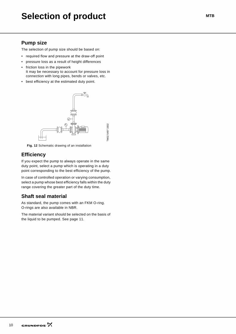
Pump sizeThe selection of pump size should be based on:
• required flow and pressure at the draw-off point• pressure loss as a result of height differences• friction loss in the pipework
It may be necessary to account for pressure loss in connection with long pipes, bends or valves, etc.
• best efficiency at the estimated duty point.
Fig. 12 Schematic drawing of an installation
EfficiencyIf you expect the pump to always operate in the same duty point, select a pump which is operating in a duty point corresponding to the best efficiency of the pump.
In case of controlled operation or varying consumption, select a pump whose best efficiency falls within the duty range covering the greater part of the duty time.
Shaft seal materialAs standard, the pump comes with an FKM O-ring. O-rings are also available in NBR.
The material variant should be selected on the basis of the liquid to be pumped. See page 11.
TM02
549
7 33
02
11
MTBPumped liquids
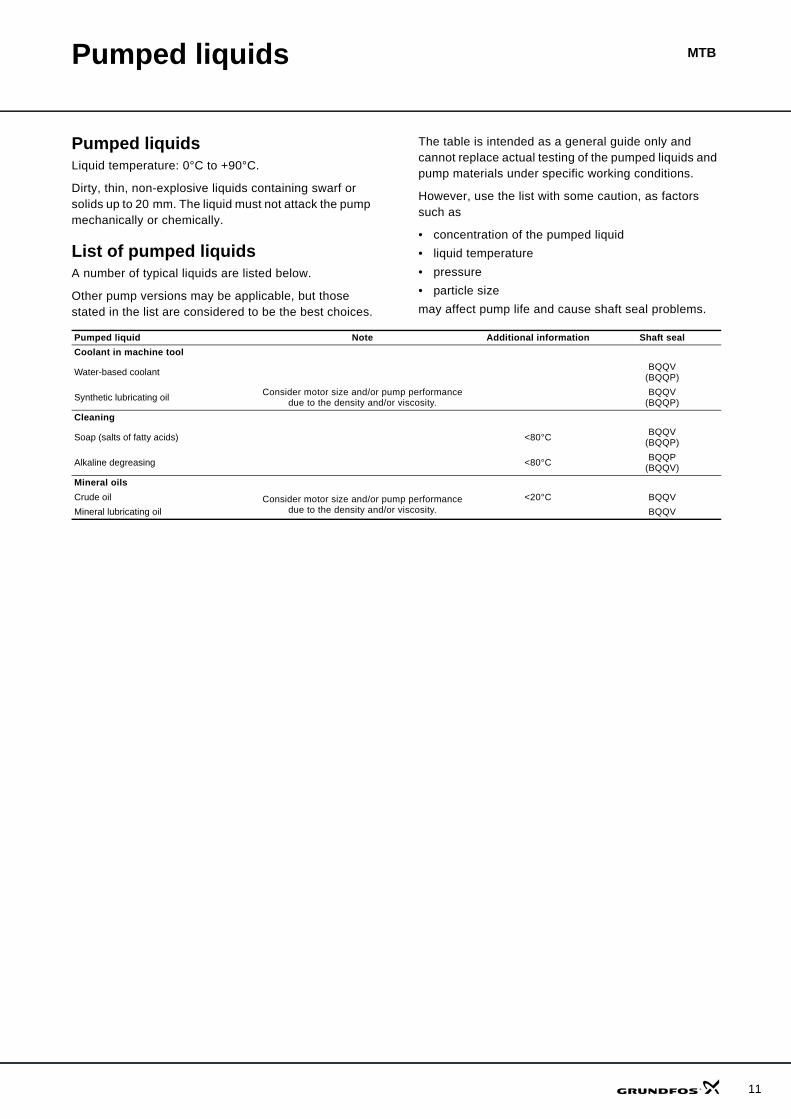
Pumped liquidsLiquid temperature: 0°C to +90°C.
Dirty, thin, non-explosive liquids containing swarf or solids up to 20 mm. The liquid must not attack the pump mechanically or chemically.
List of pumped liquidsA number of typical liquids are listed below.
Other pump versions may be applicable, but those stated in the list are considered to be the best choices.
The table is intended as a general guide only and cannot replace actual testing of the pumped liquids and pump materials under specific working conditions.
However, use the list with some caution, as factors such as
• concentration of the pumped liquid• liquid temperature• pressure• particle sizemay affect pump life and cause shaft seal problems.
Pumped liquid Note Additional information Shaft sealCoolant in machine tool
Water-based coolant BQQV(BQQP)
Synthetic lubricating oil Consider motor size and/or pump performance due to the density and/or viscosity.
BQQV(BQQP)
Cleaning
Soap (salts of fatty acids) <80°C BQQV(BQQP)
Alkaline degreasing <80°C BQQP(BQQV)
Mineral oilsCrude oil Consider motor size and/or pump performance
due to the density and/or viscosity.<20°C BQQV
Mineral lubricating oil BQQV
12
13
MTBCurve charts
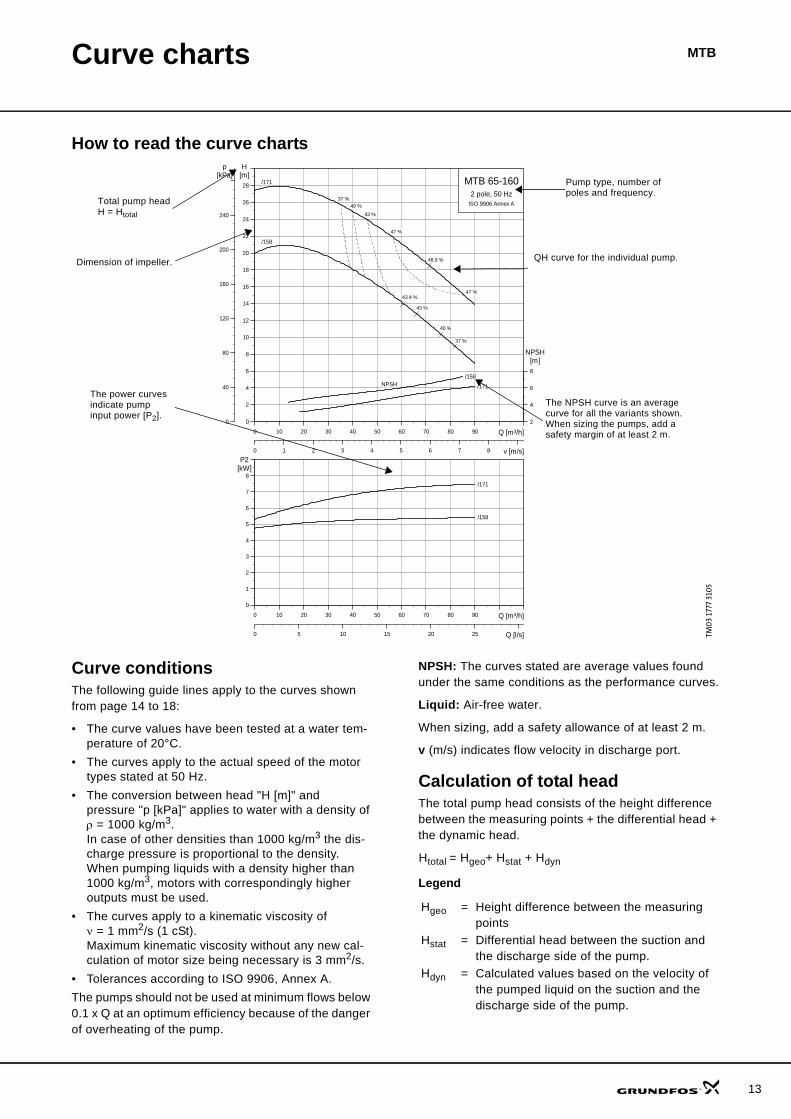
How to read the curve charts
Curve conditionsThe following guide lines apply to the curves shown from page 14 to 18:
• The curve values have been tested at a water tem-perature of 20°C.
• The curves apply to the actual speed of the motor types stated at 50 Hz.
• The conversion between head "H [m]" and pressure "p [kPa]" applies to water with a density of ρ = 1000 kg/m3.In case of other densities than 1000 kg/m3 the dis-charge pressure is proportional to the density.When pumping liquids with a density higher than 1000 kg/m3, motors with correspondingly higher outputs must be used.
• The curves apply to a kinematic viscosity of ν = 1 mm2/s (1 cSt).Maximum kinematic viscosity without any new cal-culation of motor size being necessary is 3 mm2/s.
• Tolerances according to ISO 9906, Annex A. The pumps should not be used at minimum flows below 0.1 x Q at an optimum efficiency because of the danger of overheating of the pump.
NPSH: The curves stated are average values found under the same conditions as the performance curves.
Liquid: Air-free water.
When sizing, add a safety allowance of at least 2 m.
v (m/s) indicates flow velocity in discharge port.
Calculation of total headThe total pump head consists of the height difference between the measuring points + the differential head + the dynamic head.
Htotal = Hgeo+ Hstat + Hdyn
Legend
TM0
3 17
77 3
105
0 10 20 30 40 50 60 70 80 90 Q [m³/h]
0
2
4
6
8
10
12
14
16
18
20
22
24
26
28
H[m]
0 1 2 3 4 5 6 7 8 v [m/s]
0
40
80
120
160
200
240
p[kPa]
2
4
6
8
[m]NPSH
MTB 65-1602 pole, 50 Hz
ISO 9906 Annex A
/171
/158
/158
/171
48.9 %
43.4 %
37 %40 %
43 %
47 %
47 %
43 %
40 %
37 %
NPSH
0 10 20 30 40 50 60 70 80 90 Q [m³/h]
0
1
2
3
4
5
6
7
8
P2[kW]
0 5 10 15 20 25 Q [l/s]
/158
/171
QH curve for the individual pump.Dimension of impeller.
The power curves indicate pump input power [P2].
The NPSH curve is an average curve for all the variants shown.When sizing the pumps, add a safety margin of at least 2 m.
Pump type, number of poles and frequency.
Total pump headH = Htotal
Hgeo = Height difference between the measuring points
Hstat = Differential head between the suction and the discharge side of the pump.
Hdyn = Calculated values based on the velocity of the pumped liquid on the suction and the discharge side of the pump.
14
Performance curves/Technical data
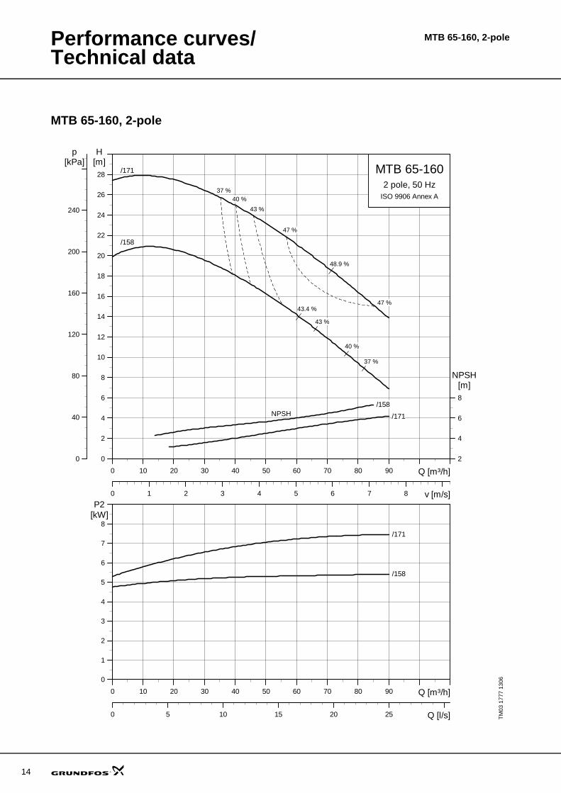
MTB 65-160, 2-pole
TM03
177
7 13
06
0 10 20 30 40 50 60 70 80 90 Q [m³/h]
0
2
4
6
8
10
12
14
16
18
20
22
24
26
28
H[m]
0 1 2 3 4 5 6 7 8 v [m/s]
0
40
80
120
160
200
240
p[kPa]
2
4
6
8
[m]NPSH
MTB 65-1602 pole, 50 Hz
ISO 9906 Annex A
/171
/158
/158
/171
48.9 %
43.4 %
37 %40 %
43 %
47 %
47 %
43 %
40 %
37 %
NPSH
0 10 20 30 40 50 60 70 80 90 Q [m³/h]
0
1
2
3
4
5
6
7
8
P2[kW]
0 5 10 15 20 25 Q [l/s]
/158
/171
MTB 65-160, 2-pole
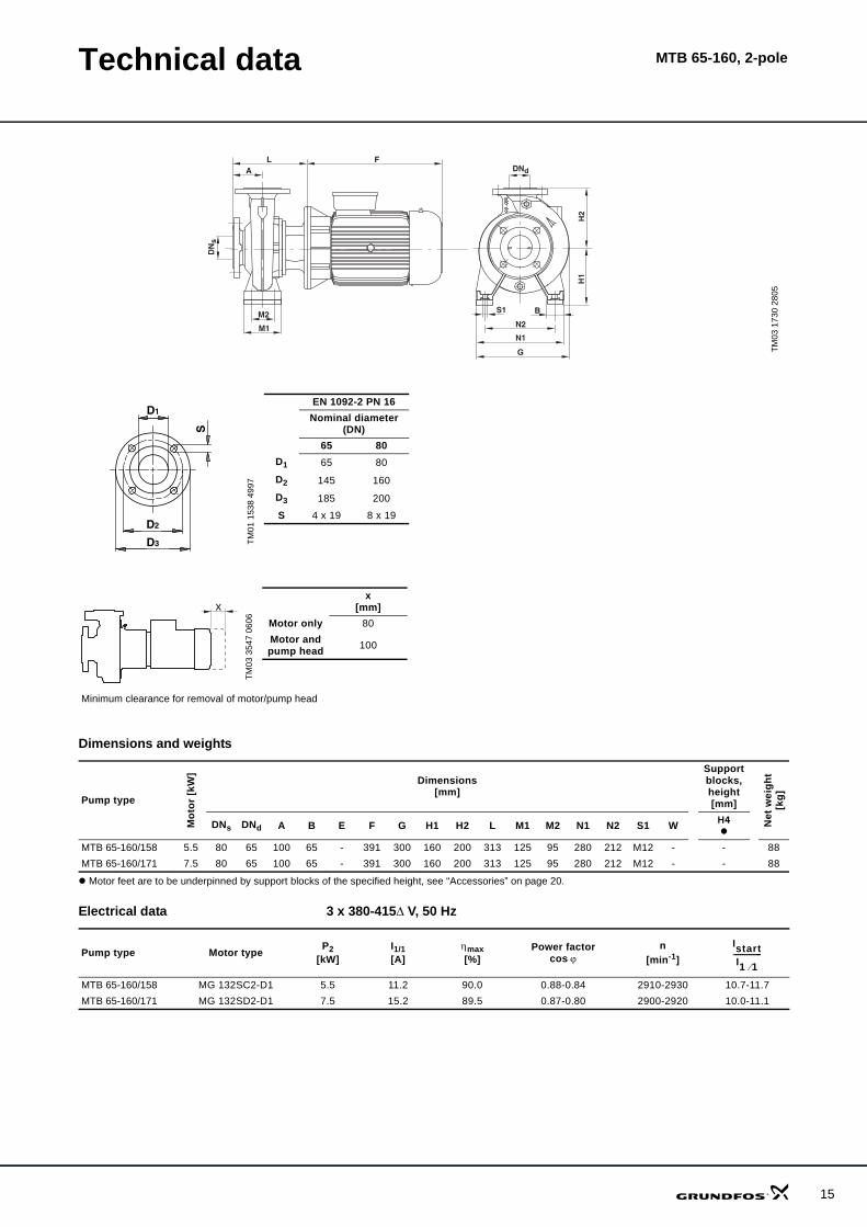
Technical data MTB 65-160, 2-pole
Dimensions and weights
Motor feet are to be underpinned by support blocks of the specified height, see “Accessories” on page 20.
Electrical data 3 x 380-415Δ V, 50 Hz
TM03
173
0 28
05
dDN
sD
N
L F
S1
H1
H2
B
N1
N2
A
M2
M1
G
TM01
153
8 49
97
EN 1092-2 PN 16Nominal diameter
(DN)65 80
D1 65 80
D2 145 160
D3 185 200
S 4 x 19 8 x 19
TM03
354
7 06
06
x[mm]
Motor only 80Motor and pump head 100
Minimum clearance for removal of motor/pump head
x
Pump type
Mot
or [k
W]
Dimensions[mm]
Support blocks,height[mm]
Net
wei
ght
[kg]
DNs DNd A B E F G H1 H2 L M1 M2 N1 N2 S1 W H4
MTB 65-160/158 5.5 80 65 100 65 - 391 300 160 200 313 125 95 280 212 M12 - - 88MTB 65-160/171 7.5 80 65 100 65 - 391 300 160 200 313 125 95 280 212 M12 - - 88
Pump type Motor type P2 [kW]
I1/1 [A]
ηmax [%]
Power factorcos ϕ
n[min-1]
MTB 65-160/158 MG 132SC2-D1 5.5 11.2 90.0 0.88-0.84 2910-2930 10.7-11.7MTB 65-160/171 MG 132SD2-D1 7.5 15.2 89.5 0.87-0.80 2900-2920 10.0-11.1
IstartI1 1⁄-------------
15
16
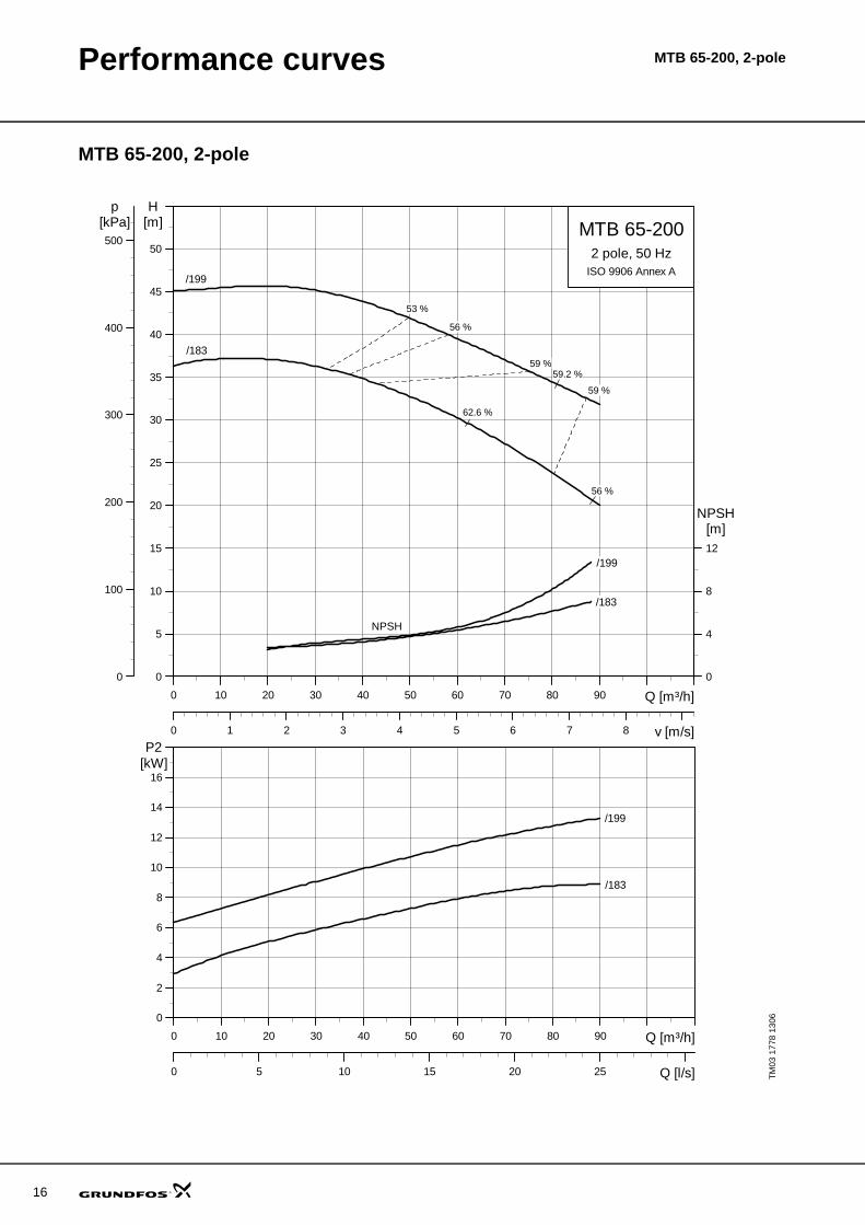
Performance curves MTB 65-200, 2-pole
MTB 65-200, 2-pole
TM03
177
8 13
06
0 10 20 30 40 50 60 70 80 90 Q [m³/h]
0
5
10
15
20
25
30
35
40
45
50
H[m]
0 1 2 3 4 5 6 7 8 v [m/s]
0
100
200
300
400
500
p[kPa]
0
4
8
12
[m]NPSH
MTB 65-2002 pole, 50 Hz
ISO 9906 Annex A
/199
/183
/183
/199
NPSH
53 %
56 %
59 %
59 %
56 %
59.2 %
62.6 %
0 10 20 30 40 50 60 70 80 90 Q [m³/h]
0
2
4
6
8
10
12
14
16
P2[kW]
0 5 10 15 20 25 Q [l/s]
/183
/199

Technical data MTB 65-200, 2-pole
Dimensions and weights
Motor feet are to be underpinned by support blocks of the specified height, see “Accessories” on page 20.
Electrical data 3 x 380-415Δ/660-690Y V, 50 Hz
TM03
172
9 28
05
S1
H1
H2
B
N1N2
G
A
W E
L FDNd
DN
s
H4
TM01
153
8 49
97
EN 1092-2 PN 16Nominal diameter
(DN)65 80
D1 65 80
D2 145 160
D3 185 200
S 4 x 19 8 x 19
TM03
354
7 06
06
x[mm]
Motoronly 110
Motor and pump head 100
Minimum clearance for removal of motor/pump head
x
Pump type
Mot
or [k
W]
Dimensions[mm]
Support blocks,height[mm]
Net
wei
ght
[kg]
DNs DNd A B E F G H1 H2 L M1 M2 N1 N2 S1 W H4
MTB 65-200/183 11 80 65 100 61 210 502 350 160 225 343 - - 320 254 M12 351 20 140MTB 65-200/199 15 80 65 100 61 210 502 350 160 225 343 - - 320 254 M12 351 20 151
Pump type Motor type P2 [kW]
I1/1 [A]
ηmax [%]
Power factorcos ϕ
n[min-1]
MTB 65-200/183 MMG 160MA2-D2 11.0 21/12.2 90.7 0.86 2930 7.3MTB 65-200/199 MMG 160MB2-D2 15.0 28/16.2 91.6 0.86 2930 7.6
IstartI1 1⁄-------------
17
18
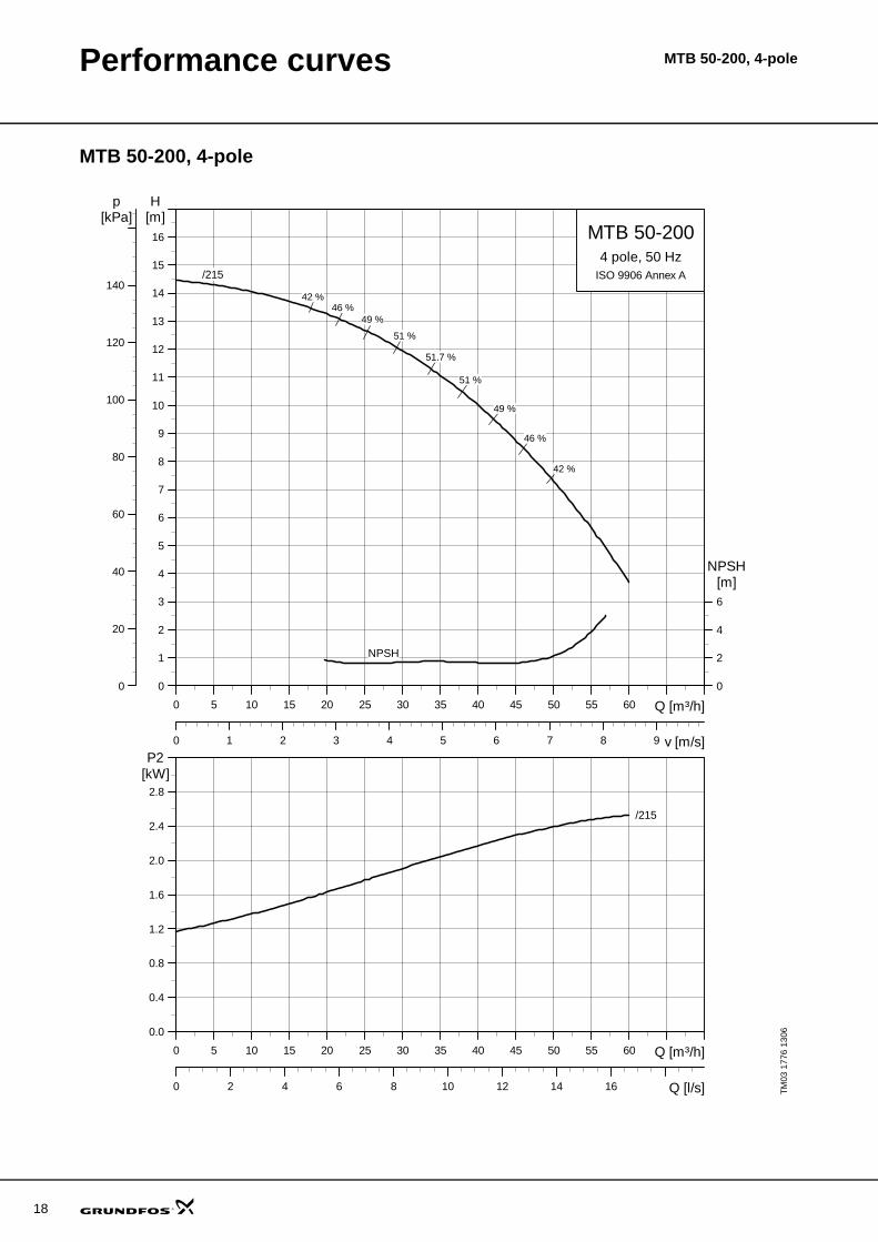
Performance curves MTB 50-200, 4-pole
MTB 50-200, 4-pole
TM03
177
6 13
06
0 5 10 15 20 25 30 35 40 45 50 55 60 Q [m³/h]
0
1
2
3
4
5
6
7
8
9
10
11
12
13
14
15
16
H[m]
0 1 2 3 4 5 6 7 8 9 v [m/s]
0
20
40
60
80
100
120
140
p[kPa]
0
2
4
6
[m]NPSH
MTB 50-2004 pole, 50 Hz
ISO 9906 Annex A
NPSH
/215
51.7 %
46 %49 %
51 %
46 %
49 %
51 %
42 %
42 %
0 5 10 15 20 25 30 35 40 45 50 55 60 Q [m³/h]
0.0
0.4
0.8
1.2
1.6
2.0
2.4
2.8
P2[kW]
0 2 4 6 8 10 12 14 16 Q [l/s]
/215
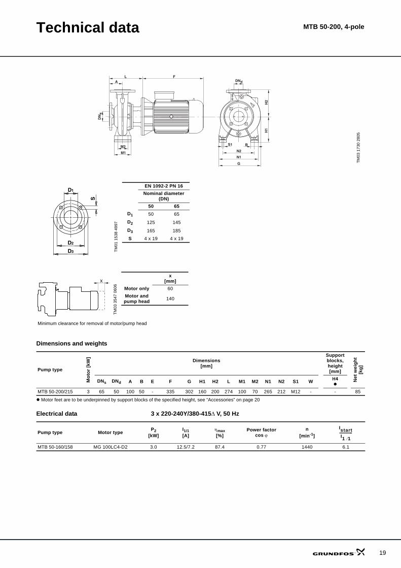
Technical data MTB 50-200, 4-pole
Dimensions and weights
Motor feet are to be underpinned by support blocks of the specified height, see “Accessories” on page 20
Electrical data 3 x 220-240Y/380-415Δ V, 50 Hz
TM03
173
0 28
05
dDN
sD
N
L F
S1
H1
H2
B
N1
N2
A
M2
M1
G
TM01
153
8 49
97
EN 1092-2 PN 16Nominal diameter
(DN)50 65
D1 50 65
D2 125 145
D3 165 185
S 4 x 19 4 x 19
TM03
354
7 06
06
x[mm]
Motor only 60Motor and pump head 140
Minimum clearance for removal of motor/pump head
x
Pump type
Mot
or [k
W]
Dimensions [mm]
Support blocks,height[mm]
Net
wei
ght
[kg]
DNs DNd A B E F G H1 H2 L M1 M2 N1 N2 S1 W H4
MTB 50-200/215 3 65 50 100 50 - 335 302 160 200 274 100 70 265 212 M12 - - 85
Pump type Motor type P2 [kW]
I1/1 [A]
ηmax [%]
Power factorcos ϕ
n[min-1]
MTB 50-160/158 MG 100LC4-D2 3.0 12.5/7.2 87.4 0.77 1440 6.1
IstartI1 1⁄-------------
19
MTB
20
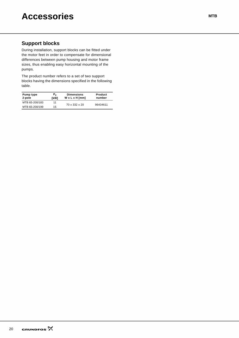
Accessories
Support blocksDuring installation, support blocks can be fitted under the motor feet in order to compensate for dimensional differences between pump housing and motor frame sizes, thus enabling easy horizontal mounting of the pumps.
The product number refers to a set of two support blocks having the dimensions specified in the following table.
Pump type2-pole
P2[kW]
DimensionsW x L x H [mm]
Product number
MTB 65-200/183 1170 x 332 x 20 96434611
MTB 65-200/199 15
21
MTBService
Spare partsAvailable spare parts kits.
• Mechanical shaft seal complete• Shaft with spacing bush• Impeller.For more information on spare parts and kits, see Grundfos WinCAPS/WebCAPS or the Grundfos Service Kit Catalogue.
22
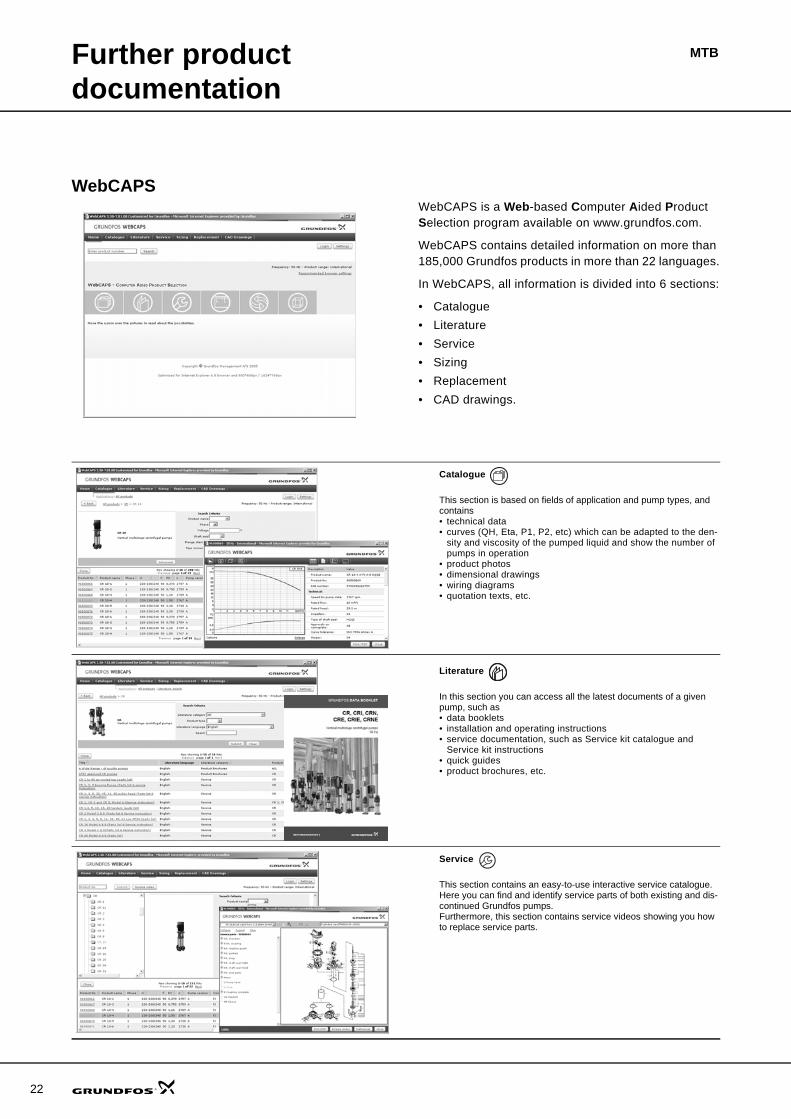
MTBFurther product documentation
WebCAPSWebCAPS is a Web-based Computer Aided Product Selection program available on www.grundfos.com.
WebCAPS contains detailed information on more than 185,000 Grundfos products in more than 22 languages.
In WebCAPS, all information is divided into 6 sections:
• Catalogue• Literature• Service• Sizing• Replacement• CAD drawings.
Catalogue
This section is based on fields of application and pump types, and contains • technical data• curves (QH, Eta, P1, P2, etc) which can be adapted to the den-
sity and viscosity of the pumped liquid and show the number of pumps in operation
• product photos• dimensional drawings• wiring diagrams• quotation texts, etc.
Literature
In this section you can access all the latest documents of a given pump, such as• data booklets• installation and operating instructions• service documentation, such as Service kit catalogue and
Service kit instructions• quick guides• product brochures, etc.
Service
This section contains an easy-to-use interactive service catalogue. Here you can find and identify service parts of both existing and dis-continued Grundfos pumps.Furthermore, this section contains service videos showing you how to replace service parts.
Further product documentation
MTB
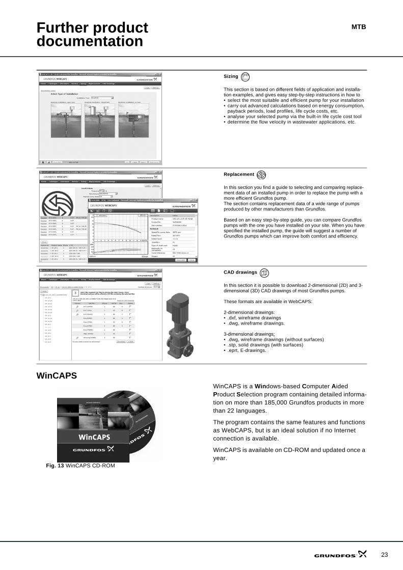
WinCAPS
Fig. 13 WinCAPS CD-ROM
WinCAPS is a Windows-based Computer Aided Product Selection program containing detailed informa-tion on more than 185,000 Grundfos products in more than 22 languages.
The program contains the same features and functions as WebCAPS, but is an ideal solution if no Internet connection is available.
WinCAPS is available on CD-ROM and updated once a year.
Sizing
This section is based on different fields of application and installa-tion examples, and gives easy step-by-step instructions in how to• select the most suitable and efficient pump for your installation• carry out advanced calculations based on energy consumption,
payback periods, load profiles, life cycle costs, etc.• analyse your selected pump via the built-in life cycle cost tool• determine the flow velocity in wastewater applications, etc.
Replacement
In this section you find a guide to selecting and comparing replace-ment data of an installed pump in order to replace the pump with a more efficient Grundfos pump. The section contains replacement data of a wide range of pumps produced by other manufacturers than Grundfos.
Based on an easy step-by-step guide, you can compare Grundfos pumps with the one you have installed on your site. When you have specified the installed pump, the guide will suggest a number of Grundfos pumps which can improve both comfort and efficiency.
CAD drawings
In this section it is possible to download 2-dimensional (2D) and 3-dimensional (3D) CAD drawings of most Grundfos pumps.
These formats are available in WebCAPS:
2-dimensional drawings:• .dxf, wireframe drawings• .dwg, wireframe drawings.
3-dimensional drawings:• .dwg, wireframe drawings (without surfaces)• .stp, solid drawings (with surfaces)• .eprt, E-drawings.
0 1
23

www.grundfos.com
96601721 0406 GBRepl. 96601721 0805 Subject to alterations.
Being responsible is our foundationThinking ahead makes it possible
Innovation is the essence
GRUNDFOS A/S . DK-8850 Bjerringbro . DenmarkTelephone: +45 87 50 14 00