ground engineering solutions for infrastructure projects: case studies
TRANSCRIPT

14/11/2014
Key note lecture DFI Chennai 2012 1
Singapore Resource PilingMalaysia India Hong Kong Indonesia
Short Course on Geotechnical Investigations for Structural Engineering
13 - 15 November 2014, IIT Gandhinagar
Madan Kumar Annam, Technical ManagerKeller India
Ground Engineering Solutions for Infrastructure Projects: Case Studies
Contents
1. Ground Engineering & Foundation Systems (15 min)
2. Geotechnical Challenges in Infrastructure Projects (5 min)
3. Case Studies
i. Technical Expertise (10 min)
ii. Design & Build Expertise (35 min)
iii. Operational Excellence (20 min)
4. Conclusions (5 min)
14/11/2014
Key note lecture DFI Chennai 2012 2
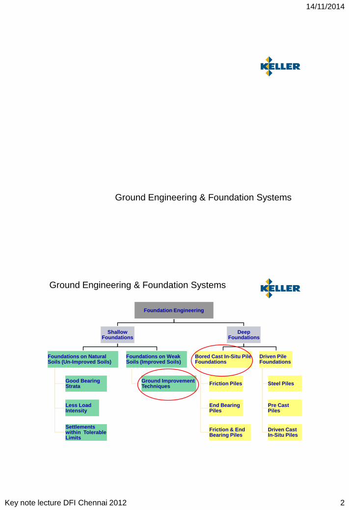
Ground Engineering & Foundation Systems
Foundation Engineering
Shallow Foundations
Foundations on Natural Soils (Un-Improved Soils)
Good Bearing Strata
Less Load Intensity
Settlements within Tolerable Limits
Foundations on Weak Soils (Improved Soils)
Ground Improvement Techniques
Deep Foundations
Bored Cast In-Situ Pile Foundations
Friction Piles
End Bearing Piles
Friction & End Bearing Piles
Driven Pile Foundations
Steel Piles
Pre Cast Piles
Driven Cast In-Situ Piles
Ground Engineering & Foundation Systems
14/11/2014
Key note lecture DFI Chennai 2012 3
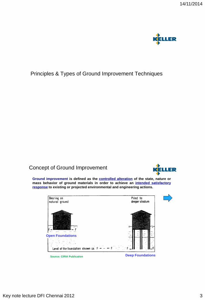
Principles & Types of Ground Improvement Techniques
Ground Improvement
Open Foundations
Deep Foundations
Ground improvement is defined as the controlled alteration of the state, nature ormass behavior of ground materials in order to achieve an intended satisfactoryresponse to existing or projected environmental and engineering actions.
Source: CIRIA Publication
Concept of Ground Improvement

14/11/2014
Key note lecture DFI Chennai 2012 4
• Densification (loose sands) : rearrangement of granular particles
• Consolidation (Cohesive) : drainage and reduction of voids
• Chemical Modification : hardening by addition of binders
• Displace & Reinforce : pushing unsuitable soils aside, installing stiffer elements
Principles of Ground Improvement
Ground Improvement
Densification
Vibro Compaction
Dynamic Compaction
Blast Densification
Compaction Grouting
Consolidation
PVD + Surcharge
Vacuum Consolidation
(Vibro Replacement)
Chemical Modification
Deep Soil Mixing
Jet Grouting
Injection Grouting
Reinforcement
Vibro Replacement
GeosyntheticReinforcement
Rigid Inclusions
(Compaction Grouting)
Others
Removal & Replacement
Thermal
Electrical
Ground Improvement Methods

14/11/2014
Key note lecture DFI Chennai 2012 5
PILES(bridge over weak soil)
REINFORCED GI TECHNIQUE(treat weak soil + strengthen with
stones, cement, etc.)
UNREINFORCED GI TECHNIQUE
(consolidation by weight)
Sett
lem
ent
0% 50% 100%
Soil Dependancy
Bridge over Poor Soil
100% 50% 0%
Ground Improvement: Soil Dependency
PILES
GROUND IMPROVEMENT TECHNIQUES
CONSOLIDATION BY SURCHARGE
Typ
ical
Set
tlem
ent
0 months 1 to 2 months > 6 months
Consolidation Time
25 to
50m
m50
to 2
00m
m>3
00 m
m
Ground Improvement: Suitability
14/11/2014
Key note lecture DFI Chennai 2012 6
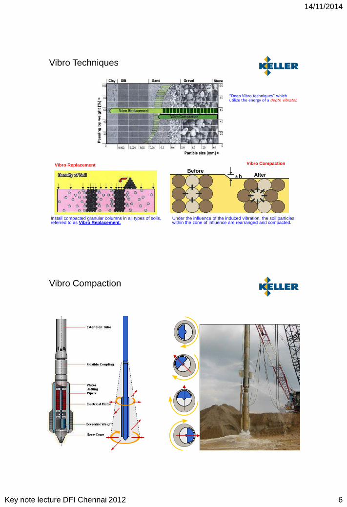
hBefore
After
Vibro Replacement Vibro Compaction
Under the influence of the induced vibration, the soil particles within the zone of influence are rearranged and compacted.
Install compacted granular columns in all types of soils, referred to as Vibro Replacement.
“Deep Vibro techniques” which utilize the energy of a depth vibrator.
Vibro Techniques
Vibro Compaction
14/11/2014
Key note lecture DFI Chennai 2012 7
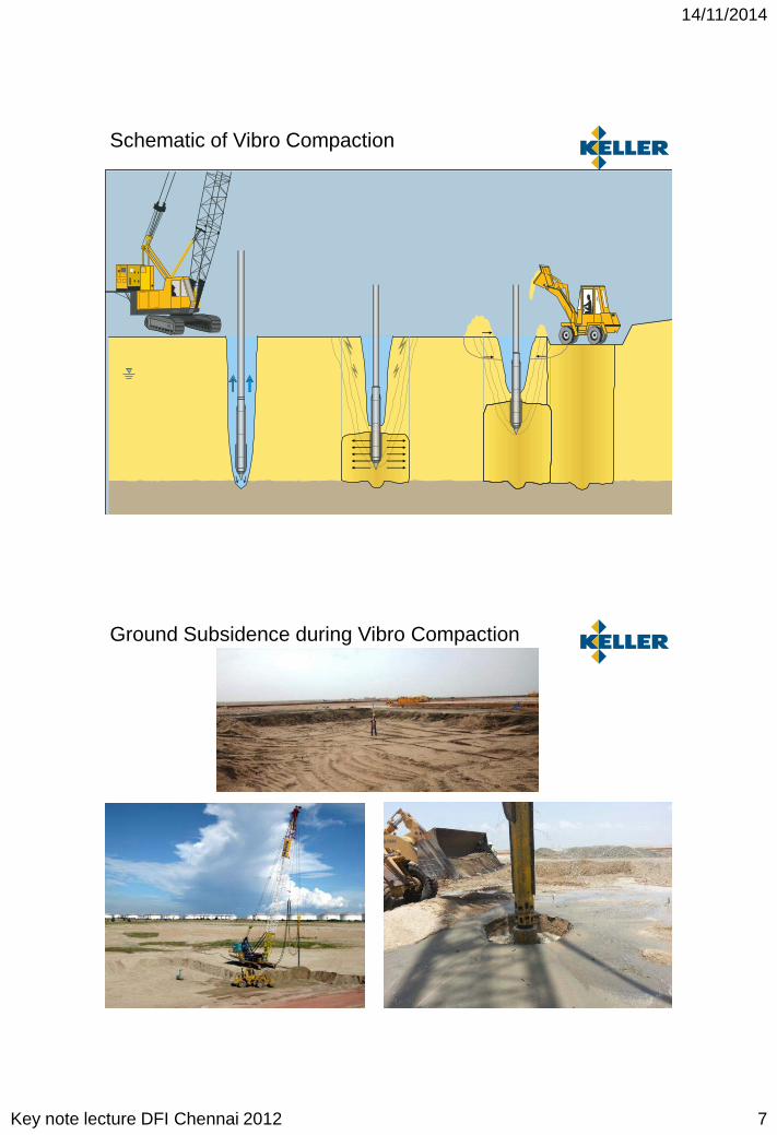
Schematic of Vibro Compaction
Ground Subsidence during Vibro Compaction
14/11/2014
Key note lecture DFI Chennai 2012 8
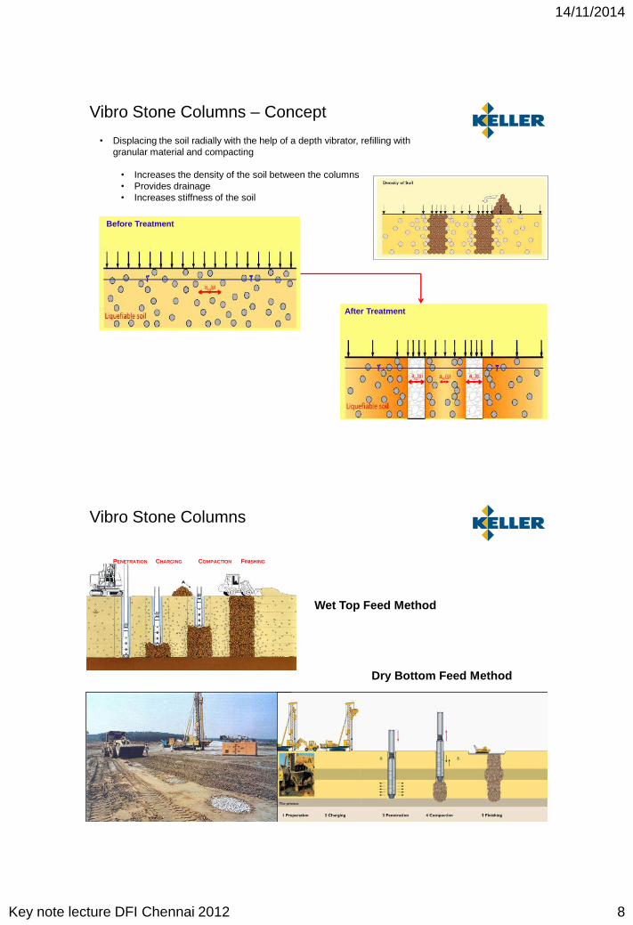
Vibro Stone Columns – Concept
• Displacing the soil radially with the help of a depth vibrator, refilling with granular material and compacting
• Increases the density of the soil between the columns• Provides drainage• Increases stiffness of the soil
Before Treatment
After Treatment
Wet Top Feed Method
Dry Bottom Feed Method
PENETRATION CHARGING COMPACTION FINISHING
Vibro Stone Columns

14/11/2014
Key note lecture DFI Chennai 2012 9
Depth Vibrator
Wet Top Feed Method
Dry Vibro Stone Columns – Process
Penetration Delivery and Compaction Process of Stones
CompletionPenetration Delivery and Compaction Process of Stones
Completion
Penetration

14/11/2014
Key note lecture DFI Chennai 2012 10
Dry Vibro Stone Columns – Execution
• Automated Real Time Monitoring of Installation Process • Reliable investigation techniques (Electric Cone Penetration Testing, SPT’s etc)• Post improvement testing by Load Tests • Good quality of Back Fill Material
Quality Control Measures – Pre and Post
eCPT’
Figure 7 Keller’s Automatic
Quality Control System(M3 / M4 Computer)
Figure 7 Keller’s Automatic
Quality Control System(M3 / M4 Computer)
Automated Real Time Quality Control

14/11/2014
Key note lecture DFI Chennai 2012 11
Mechanical Cutting
Mechanical Mixing
Full Completed DSM Column
DSM Operation in field
Mechanical mixing of in-situ soils with a binder (e.g. cement, slag, lime, fly ash etc.) to improve shear strength and to reduce permeability of weak deposits.
Deep Soil Mixing
Very Soft Clay / Slime Cu = 5 to 10 kPa
Pile Like Element Cu = 100 to 2000 kPa
Deep Soil Mixing

14/11/2014
Key note lecture DFI Chennai 2012 12
SoilfracTM Compensation Grouting:
Fracturing & Heaving of the soil with grout
TAM
SoilcreteTM Jet Grouting:
Eroding and mixing the soil with grout
Grouting:
Penetrating & filling soil voids with grout
TAM
CompactionGrouting:
Compaction/ Densification of soil with
stiff grout bulb
Introduction of liquid or dry binder (esp. cement material) into the weak soil mass, to improve its strength, stiffness and reduce permeability.
Grouting Techniques
• Suitability of Technique
• Are the encountered soil and suggested technique fundamentally compatible?
• Technical Compliance
• Does the suggested technique satisfy the design requirements ? (strength or stiffness?)
• Availability of Material
• Is the required material (stone, cement) readily available?
• Cost
• Is the proposed technique within the budget? What is the cost of time when there is saving?
• Protection of the Environment
• Does the suggested technique reduce or avoid pollution? Is the technique resource efficient?
Choice of Technique
14/11/2014
Key note lecture DFI Chennai 2012 13
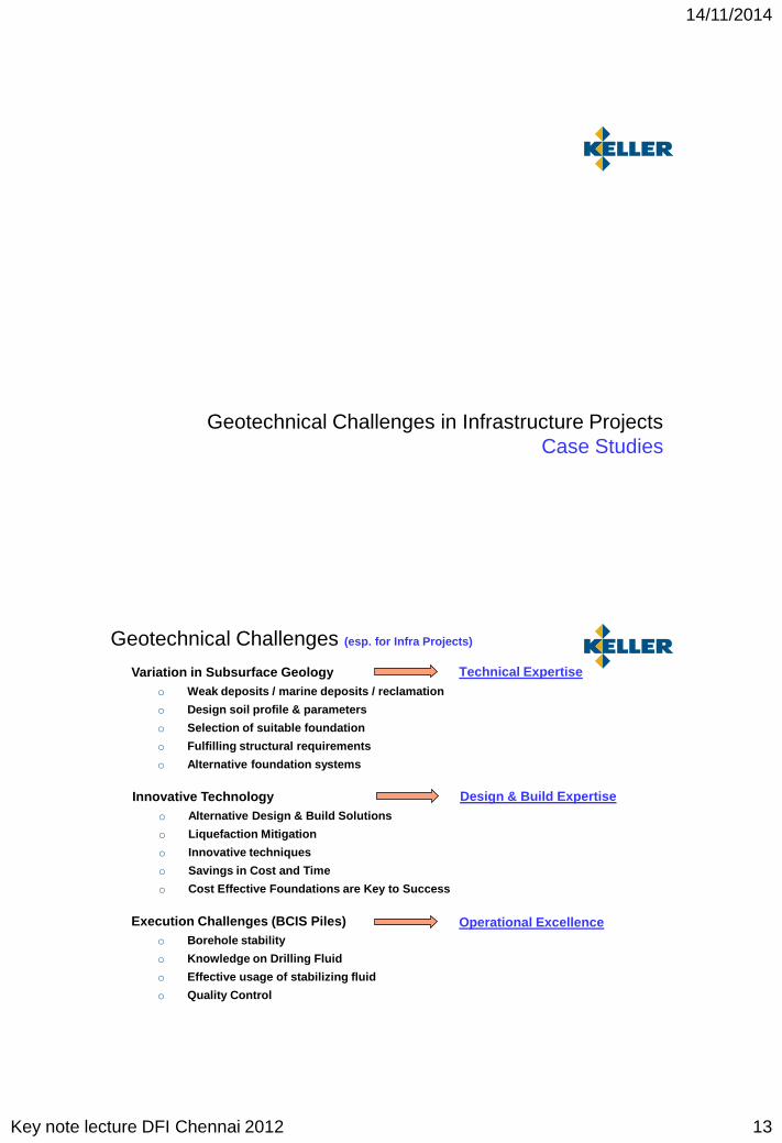
Geotechnical Challenges in Infrastructure ProjectsCase Studies
Geotechnical Challenges (esp. for Infra Projects)
Variation in Subsurface Geologyo Weak deposits / marine deposits / reclamation
o Design soil profile & parameters
o Selection of suitable foundation
o Fulfilling structural requirements
o Alternative foundation systems
Execution Challenges (BCIS Piles)o Borehole stability
o Knowledge on Drilling Fluid
o Effective usage of stabilizing fluid
o Quality Control
Innovative Technologyo Alternative Design & Build Solutions
o Liquefaction Mitigation
o Innovative techniques
o Savings in Cost and Time
o Cost Effective Foundations are Key to Success
Technical Expertise
Operational Excellence
Design & Build Expertise
14/11/2014
Key note lecture DFI Chennai 2012 14
Design Challenges
o Weak deposits / marine deposits / reclamation
o Design soil profile & parameters
o Selection of suitable foundation
o Fulfilling structural requirements
o Alternative foundation systems
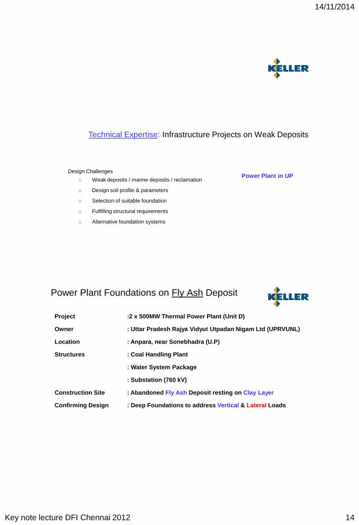
Technical Expertise: Infrastructure Projects on Weak Deposits
Power Plant in UP
Project :2 x 500MW Thermal Power Plant (Unit D)
Owner : Uttar Pradesh Rajya Vidyut Utpadan Nigam Ltd (UPRVUNL)
Location : Anpara, near Sonebhadra (U.P)
Structures : Coal Handling Plant
: Water System Package
: Substation (760 kV)
Construction Site : Abandoned Fly Ash Deposit resting on Clay Layer
Confirming Design : Deep Foundations to address Vertical & Lateral Loads
Power Plant Foundations on Fly Ash Deposit
14/11/2014
Key note lecture DFI Chennai 2012 15
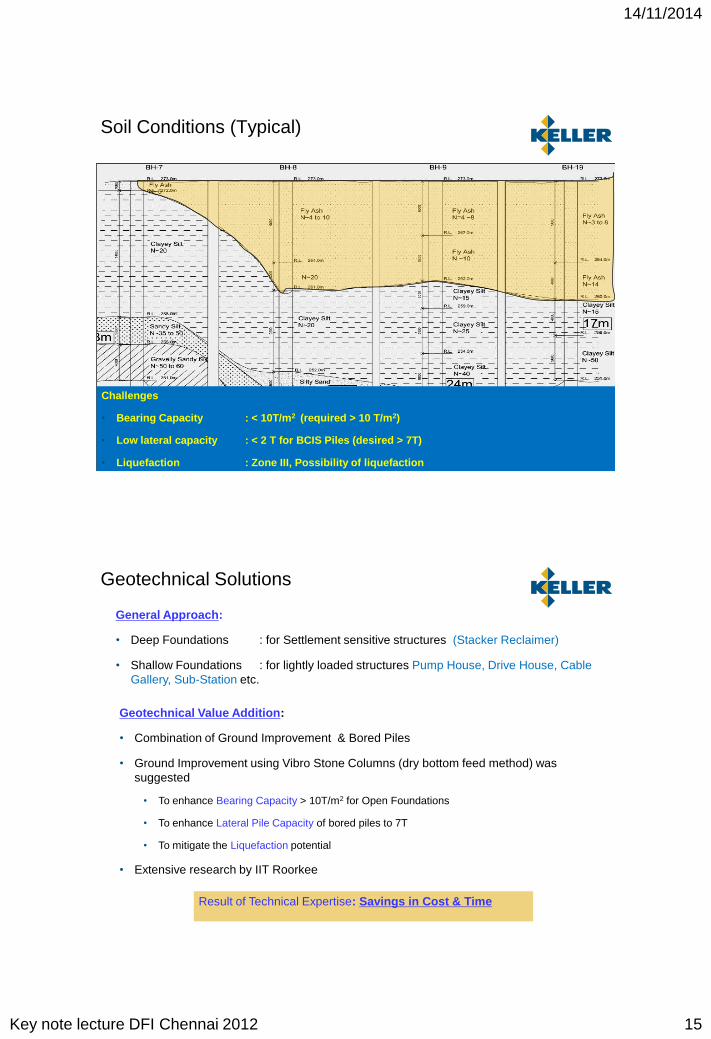
Soil Conditions (Typical)
Challenges
• Bearing Capacity : < 10T/m2 (required > 10 T/m2)
• Low lateral capacity : < 2 T for BCIS Piles (desired > 7T)
• Liquefaction : Zone III, Possibility of liquefaction
Geotechnical Value Addition:
• Combination of Ground Improvement & Bored Piles
• Ground Improvement using Vibro Stone Columns (dry bottom feed method) was suggested
• To enhance Bearing Capacity > 10T/m2 for Open Foundations
• To enhance Lateral Pile Capacity of bored piles to 7T
• To mitigate the Liquefaction potential
• Extensive research by IIT Roorkee
Geotechnical Solutions
General Approach:
• Deep Foundations : for Settlement sensitive structures (Stacker Reclaimer)
• Shallow Foundations : for lightly loaded structures Pump House, Drive House, Cable Gallery, Sub-Station etc.
Result of Technical Expertise: Savings in Cost & Time

14/11/2014
Key note lecture DFI Chennai 2012 16
Single Column Load Test Group Column Load Test
Addressing Bearing Capacity
• Ground Improvement using Vibro Stone Columns (dry bottom feed method)
• Stone columns terminated into the underlying stiff clayey silt or silty clay
• Single and group column load tests were conducted to ensure performance
Addressing Lateral Capacity of Piles
Stone Columns of 0.5m dia. Installed at the centre and surrounding two piles
Stone Column of 0.5m dia. installed at the centre and 0.75m dia installed surrounding two piles

14/11/2014
Key note lecture DFI Chennai 2012 17
• The deformations observed to be within allowable limits (5mm) at design load of 7T
• 0.5m dia. stone column grid was adopted for main works
Addressing Lateral Capacity of Piles
0
2
4
6
8
10
12
14
16
18
20
0 5 10 15 20 25
Set
tlem
ent,
mm
Load in Tons
Lateral Pile Load Test Results
ITP-1
ITP-2
Installation of Stone Columns & Bored Piles

14/11/2014
Key note lecture DFI Chennai 2012 18
Design & Build Expertise: Innovative Technology
Innovative Technologyo Alternative Design & Build Solutions
o Liquefaction Mitigation
o Innovative techniques
o Savings in Cost and Time
o Cost Effective Foundations are Key to Success
Industrial Plant @ Singapore
Industrial Plant @ Hajipir
Multi-storeyed tower @ NCR
Residential building @ Chennai
Wind Turbines @ Kolhapur
Definition:
Alternative or approach that best fits the situation, employs resources in a most effective and efficient manner, and yields the highest possible return under the given circumstances.
Approaches
• Good data – Extensive Soil Investigation (Soil Data)– Real / Factual Soil Data
• Physics – How are forces resisted (Analysis & Design)• Materials – Carbon footprint, muck disposal (Environment)• Cost – Savings in materials (Foundation Optimization)• Time – How long do you take (Savings in Time)
Opportunities for Optimization

14/11/2014
Key note lecture DFI Chennai 2012 19
Design & Build Expertise: Innovative Technology
Innovative Technologyo Alternative Design & Build Solutions
o Liquefaction Mitigation
o Innovative techniques
o Savings in Cost and Time
o Cost Effective Foundations are Key to Success
Industrial Plant @ Singapore
Industrial Plant @ Hajipir
Multi-storeyed tower @ NCR
Residential building @ Chennai
Wind Turbines @ Kolhapur
Factories on Reclaimed Soil – Shipyard
Land reclamation
Fill thickness 5m to 30m
Qc about 4 to 6 MPa
RD about 30% to 40%

14/11/2014
Key note lecture DFI Chennai 2012 20
Factories on Reclaimed Soil – Structure
Hull shop
Automated steel plate cutting and assembly 180m x 670m 50m tall
Factories on Reclaimed Soil – Structure
• Foundation for columns• Foundation for floor slab

14/11/2014
Key note lecture DFI Chennai 2012 21
Factories on Reclaimed Soil – Structure
Automation => Sensitive to settlements
Factories on Reclaimed Soil – Loading
Steel Plate Storage
Automated cutting and
forming
Automated assembly
Manual assembly
Finished product delivery
Settlements
Steel Storage Area < 100mm
Other Areas < 50mm
Differential ≈ 1 in 1000

14/11/2014
Key note lecture DFI Chennai 2012 22
Legend
Existing Boreholes (56 nos)
Existing CPT
Additional Boreholes
Additional CPT (> 60 nos. – more where you need them)
Collect Extensive Soil Information
Factories on Reclaimed Soil – Soil Investigation
Factories on Reclaimed Soil – Soil Conditions
Loose reclaimed SAND
Stiff to very stiff clay
Soft to firm clayHard clayey silt

14/11/2014
Key note lecture DFI Chennai 2012 23
Factories on Reclaimed Soil – Geotechnical Solution
Conforming : Driven Piles
Factories on Reclaimed Soil – Site
SurchargePVD rigs
VC cranes

14/11/2014
Key note lecture DFI Chennai 2012 24
Factories on Reclaimed Soil – Testing
Post CPT
Factories on Reclaimed Soil – Shipyard
Vibro Compaction Rigs
PVD Rigs
• Physics (NSF)• Cost • Time• Materials & Carbon Footprint

14/11/2014
Key note lecture DFI Chennai 2012 25
Design & Build Expertise: Innovative Technology
Innovative Technologyo Alternative Design & Build Solutions
o Liquefaction Mitigation
o Innovative techniques
o Savings in Cost and Time
o Cost Effective Foundations are Key to Success
Industrial Plant @ Singapore
Industrial Plant @ Hajipir
Multi-storeyed tower @ NCR
Residential building @ Chennai
Wind Turbines @ Kolhapur
Project Background
• Project : Chemical Plant
• Location : Kutch region, Gujarat State, India
• Structures: Industrial Structures
• Plot Area : 25 Ha.
• Main Structures: • Sulphate of Potash (SOP)• Bromine Plant• Cogen Plant
• Other Structures: • Storage Tanks• Workshops• Treatment Plants• Ancillary structures and other Amenities• Buildings and other Storage Areas
14/11/2014
Key note lecture DFI Chennai 2012 26
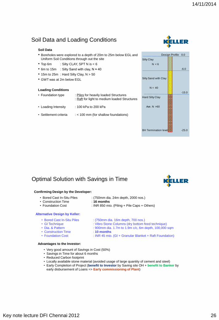
Soil Data
• Boreholes were explored to a depth of 20m to 25m below EGL and Uniform Soil Conditions through out the site
• Top 6m : Silty CLAY, SPT N is < 6
• 6m to 15m : Silty Sand with clay, N ≈ 40
• 15m to 25m : Hard Silty Clay, N > 50
• GWT was at 2m below EGL
Loading Conditions
• Foundation type : Piles for heavily loaded Structures: Raft for light to medium loaded Structures
• Loading Intensity : 100 kPa to 200 kPa
• Settlement criteria : < 100 mm (for shallow foundations)
Soil Data and Loading Conditions
Design Profile
Silty Clay
N < 6
Silty Sand with Clay
N = 40
Hard Silty Clay
Ave. N >60
BH Termination level
0.0
-6.0
-15.0
-25.0
Optimal Solution with Savings in Time
Confirming Design by the Developer:
• Bored Cast In-Situ Piles : (750mm dia. 24m depth, 2000 nos.)• Construction Time : 16 months• Foundation Cost : INR 850 mio. (Piling + Pile Caps + Others)
Alternative Design by Keller:
• Bored Cast In-Situ Piles : (750mm dia. 16m depth, 700 nos.)• GI Technique : Vibro Stone Columns (dry bottom feed technique)• Dia. & Pattern : 900mm dia. 1.7m to 1.9m c/c, 6m depth, 100,000 sqm• Construction Time : 10 months• Foundation Cost : INR 45 mio. (GI + Granular Blanket + Raft Foundation)
Advantages to the Investor:
• Very good amount of Savings in Cost (50%)• Savings in Time for about 6 months• Reduced Carbon footprint• Locally available stone material (avoided usage of large quantity of cement and steel)• Early Completion of Project (benefit to Investor by Saving site OH + benefit to Banker by
early disbursement of Loans => Early commissioning of Plant)

14/11/2014
Key note lecture DFI Chennai 2012 27
Cost Effective Alternate Solutions
Pile Foundations Sulphate of Potash (SOP) Bromine Plant Cogen Plant
Shallow Foundations on GI Storage tanks Workshop Treatment Plant Ancillary structures and amenities Buildings and other storage areas
Foundation Alternatives & Performance
• Heavily loaded structures were supported on 750mm dia. and 16m long BCIS Piles
• Lightly loaded structures were rested on GI using Vibro Stone Columns (dry bottom feed method)
• Load Tests were conducted on Piles & GI and performance proved satisfactory.
0
5
10
15
20
0 25 50 75 100
Set
tlem
ent,
mm
Load in TonsRoutine Stone Column Load Test
14/11/2014
Key note lecture DFI Chennai 2012 28
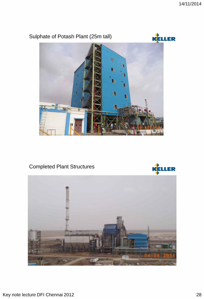
Sulphate of Potash Plant (25m tall)
Completed Plant Structures
14/11/2014
Key note lecture DFI Chennai 2012 29
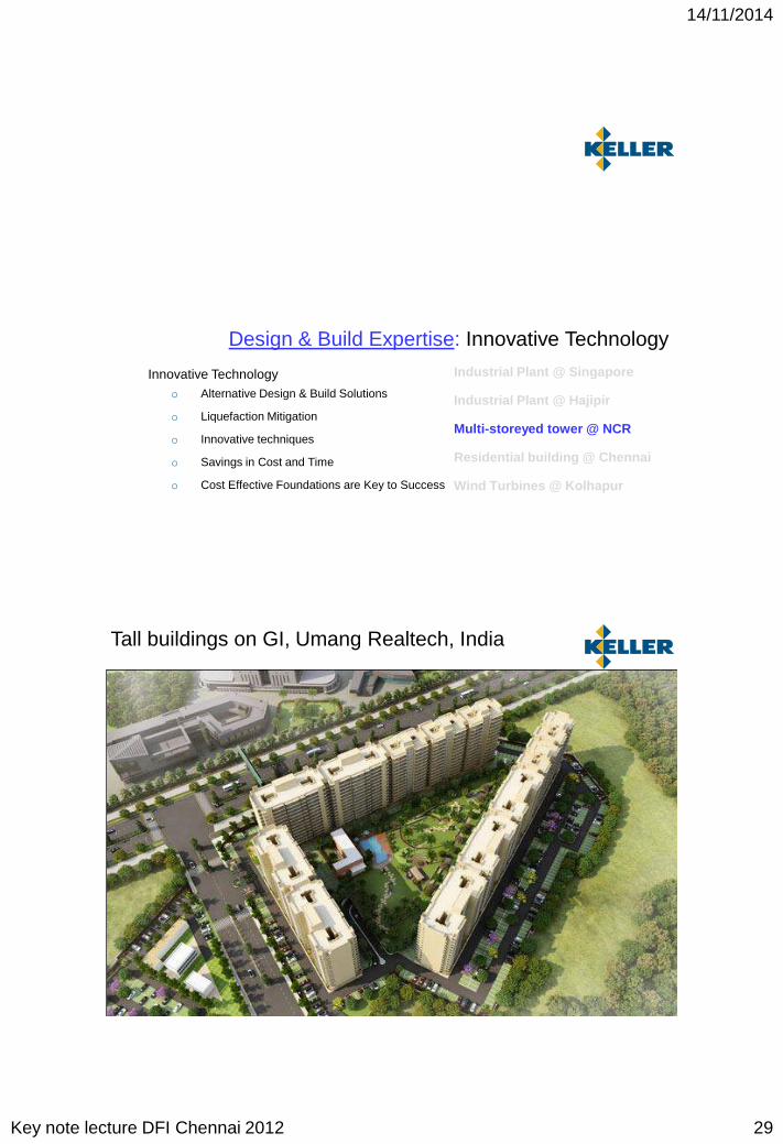
Design & Build Expertise: Innovative Technology
Innovative Technologyo Alternative Design & Build Solutions
o Liquefaction Mitigation
o Innovative techniques
o Savings in Cost and Time
o Cost Effective Foundations are Key to Success
Industrial Plant @ Singapore
Industrial Plant @ Hajipir
Multi-storeyed tower @ NCR
Residential building @ Chennai
Wind Turbines @ Kolhapur
Tall buildings on GI, Umang Realtech, India

14/11/2014
Key note lecture DFI Chennai 2012 30
Project Background
• Project : Summer Palm
• Location : NCR Region
• Building : G + 14 floors, 13 Towers
• Raft Area : 12,000 sq.m
• Plot Area : 12 Acres
Soil Data & Loading Conditions
Soil Data
• Boreholes were explored to a depth of 20m to 25m below EGL and Uniform Soil Conditions are found through out the site
• Top 7.5m : Silty SAND, SPT N varies from 6 to 17
• 7.5m to 10.5m : Loose med. Sandy SILT, N ≈ 17 to 23
• 10m to 20m : Med. Dense Sandy SILT, N > 40
• GWT was at 2m below EGL during investigation
Loading Conditions
• Foundation type : Raft
• Loading Intensity : 150 kPa
• Settlement criteria : < 75 mm

14/11/2014
Key note lecture DFI Chennai 2012 31
Bearing Capacity & Liquefaction
Main Technical Concerns are………………
• Low Bearing Capacity due to weak soil
• Total & Differential Settlements
• Mitigating Liquefaction (Zone 4, 0.24g)
Required Geotechnical Solution………
Reinforcement To improve composite shear strength
Compaction in granular/soft subsoil To increase composite compression modulus
Large Drainage path To improve overall permeability
Mitigate Liquefaction
Proposed Ground Improvement Scheme
Vibro Stone Columns with Dry Bottom Feed Technique
• Column diameter = 900mm
• Grid pattern = Square grid
• Column spacing = 2.0m c/c
• Treatment depth = 8m below EGL
• Area replacement = 16%
14/11/2014
Key note lecture DFI Chennai 2012 32
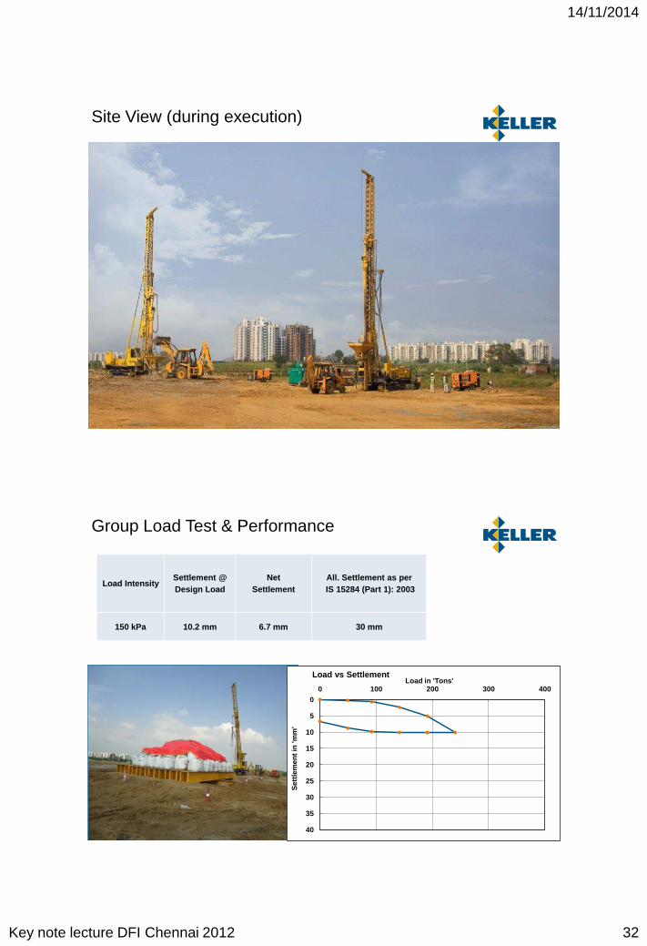
Site View (during execution)
Group Load Test & Performance
0
5
10
15
20
25
30
35
40
0 100 200 300 400
Set
tlem
ent
in 'm
m'
Load in 'Tons'Load vs Settlement
Load IntensitySettlement @Design Load
NetSettlement
All. Settlement as perIS 15284 (Part 1): 2003
150 kPa 10.2 mm 6.7 mm 30 mm
14/11/2014
Key note lecture DFI Chennai 2012 33
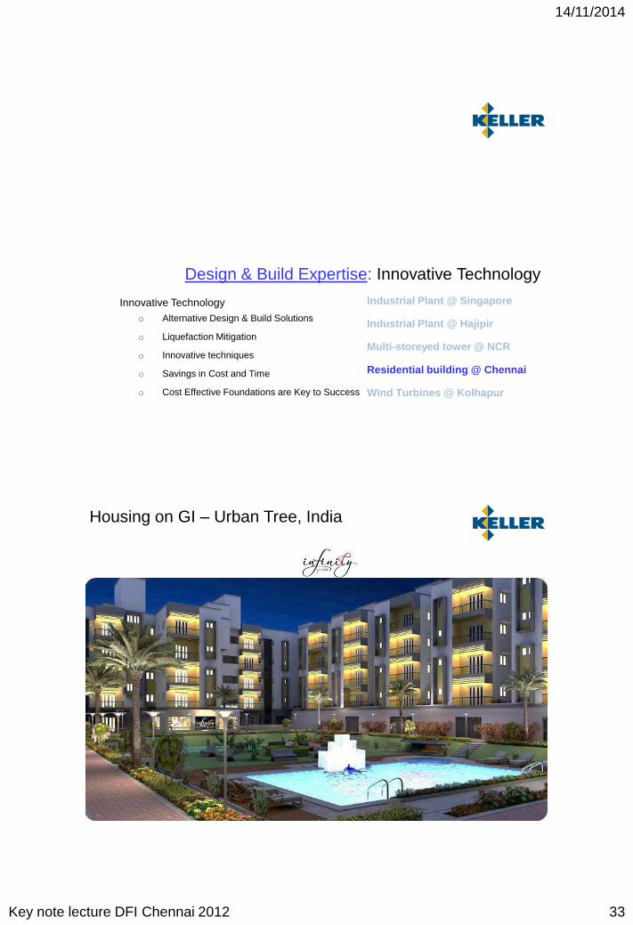
Design & Build Expertise: Innovative Technology
Innovative Technologyo Alternative Design & Build Solutions
o Liquefaction Mitigation
o Innovative techniques
o Savings in Cost and Time
o Cost Effective Foundations are Key to Success
Industrial Plant @ Singapore
Industrial Plant @ Hajipir
Multi-storeyed tower @ NCR
Residential building @ Chennai
Wind Turbines @ Kolhapur
Housing on GI – Urban Tree, India

14/11/2014
Key note lecture DFI Chennai 2012 34
Project Background
• Project : INFINITY, Porur
• Location : Porur Gardens, Chennai
• Building : Stilt + 4 floors
• Total flats: 198 units
• Raft Area : 5600 sq.m
• Plot Area : 2.5 Acres (~100m x 100m)
Soil Data
• 4 Boreholes were explored to a depth of 20m to 25m below EGL and Uniform Soil Conditions through out the site
• Top 6m : Silty sandy CLAY with 20 to 40% fines
• Below 6m : Medium dense SAND up to 12m, followed firm to stiff silty CLAY up to explored depth
• GWT was at 3m below EGL during investigation (Sep 2012)
Loading Conditions
• Foundation type : Raft
• Loading Intensity : 100 kPa
• Settlement criteria : < 100 mm
Soil Data and Loading Conditions

14/11/2014
Key note lecture DFI Chennai 2012 35
Optimal Solution with Savings in Time
Confirming Design by the Developer:
• Driven Cast In-Situ Piles : (5000mm dia. 24m depth, 800 nos.)• Construction Time : 8 months• Foundation Cost : INR 45 mio. (Piling + Pile Caps + Others)
Alternative Design by Keller:
• GI Technique : Vibro Stone Columns (dry bottom feed technique)• Dia. & Pattern : 900mm dia. 1.7m to 1.9m c/c, 6m depth, 5,600 sqm• Construction Time : 2 months• Foundation Cost : INR 45 mio. (GI + Granular Blanket + Raft Foundation)
Advantages to the Investor:
• No Savings in Cost• Savings in Time for about 6 months• Reduced Carbon footprint• Locally available stone material (avoided usage of large quantity of cement and steel)• Early Completion of Project (benefit to Investor by Saving site OH + benefit to Banker by
early disbursement of Loans => Early completion and delivered to End User)
Vibro Stone Columns with Dry Bottom Feed Technique
• Column diameter = 900mm
• Grid pattern = Square grid
• Column spacing = 1.7m & 1.9m
• Treatment depth = 6m below EGL
• Area replacement = 18% to 22%
Proposed Ground Improvement Scheme
14/11/2014
Key note lecture DFI Chennai 2012 36
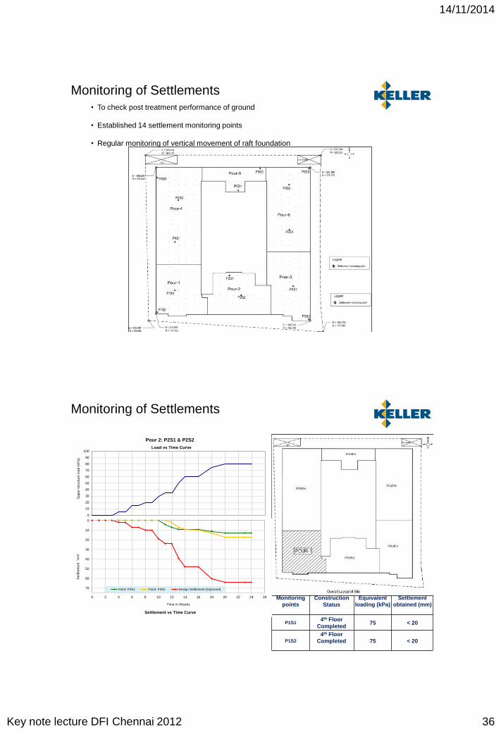
• To check post treatment performance of ground
• Established 14 settlement monitoring points
• Regular monitoring of vertical movement of raft foundation
Monitoring of Settlements
Monitoring points
Construction Status
Equivalentloading (kPa)
Settlement obtained (mm)
P1S14th Floor
Completed75 < 20
P1S24th Floor
Completed 75 < 20
Monitoring of Settlements
0
10
20
30
40
50
60
70
80
90
100
Sup
er s
truc
ture
load
(kP
a)
Pour 2: P2S1 & P2S2
Load vs Time Curve
0
10
20
30
40
50
60
70
0 2 4 6 8 10 12 14 16 18 20 22 24 26
Set
tlem
ent
'mm
'
Time in Weeks
Point: P2S1 Point: P2S2 Design Settlement (improved)
Settlement vs Time Curve
14/11/2014
Key note lecture DFI Chennai 2012 37
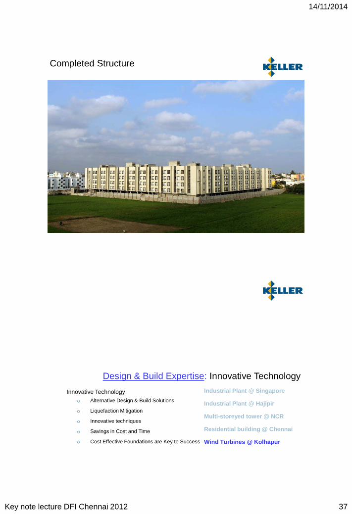
Completed Structure
Design & Build Expertise: Innovative Technology
Innovative Technologyo Alternative Design & Build Solutions
o Liquefaction Mitigation
o Innovative techniques
o Savings in Cost and Time
o Cost Effective Foundations are Key to Success
Industrial Plant @ Singapore
Industrial Plant @ Hajipir
Multi-storeyed tower @ NCR
Residential building @ Chennai
Wind Turbines @ Kolhapur
14/11/2014
Key note lecture DFI Chennai 2012 38
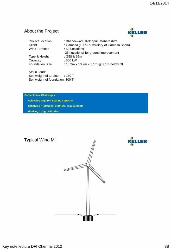
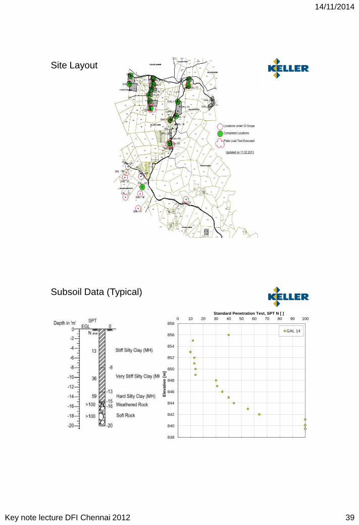
Project Location : Bhendewadi, Kolhapur, MaharashtraClient : Gamesa (100% subsidiary of Gamesa Spain)Wind Turbines : 58 Locations
25 (locations) for ground improvementType & Height : G58 & 65mCapacity : 850 kWFoundation Size : 10.2m x 10.2m x 1.1m @ 2.1m below GL
Static LoadsSelf weight of turbine : 150 TSelf weight of foundation: 300 T
About the Project
Geotechnical Challenges
• Achieving required Bearing Capacity
• Satisfying ‘Rotational Stiffness’ requirements
• Working in high altitudes
Typical Wind Mill
14/11/2014
Key note lecture DFI Chennai 2012 39
Site Layout
838
840
842
844
846
848
850
852
854
856
8580 10 20 30 40 50 60 70 80 90 100
Ele
vati
on
[m
]
Standard Penetration Test, SPT N [ ]
GAL 14
Subsoil Data (Typical)

14/11/2014
Key note lecture DFI Chennai 2012 40
Typical Scheme & Activities
Installed Wind Mills

14/11/2014
Key note lecture DFI Chennai 2012 41
0
2
4
6
8
10
12
0 50 100 150 200 250 300
Set
tlem
ent,
mm
Pressure in KN/m2
Initial Single Column Load Test
• Load Intensity = 200 KPa• Depth of fdn, Df = 2.1m • Size of fdn, B = 10.2m• P, applied load = 200 KPa• w, obs settlement = 3.05mm• μ, Poisson’s ratio = 0.33• Es = Iw(π/4)(p/w)*D*(1-μ2)• G = E/2*(1+μ)
• Estimated KR, PLT > Required KR
Load Test (Satisfying Rotational Stiffness)
Typical Load Test Graph Determination of Es = Es, stat from the slope of the curve till elastic limit.
G = Es/2(1+ μ)
1. 2.
3. 4.Es = (π/4)(p/w)*D*(1-μ2) Rotational Stiffness
.....DNV/RISO
Rotational Stiffness

14/11/2014
Key note lecture DFI Chennai 2012 42
Concluding Remarks: Technical & Design Expertise
1. Ground improvement techniques such as Dry Vibro Stone Columns, Deep Soil Mixing, Jet Grouting, Prefabricated Vertical Drains can be used to provide Optimal Foundations.
2. These techniques can be used both for heavy, tall & settlement sensitive structures and also for smaller simpler structures
3. Optimal Foundations offer savings in cost, time, materials, convenience and protection to the environment
4. Excellent soil information, a correct choice of technique, good equipment, experienced people, testing and monitoring during and after construction is essential for successful project completion.
Operational Excellence: Bored Piling Experience
Execution Challenges (BCIS Piles)o Borehole Stability
o Knowledge on Drilling Fluid
o Effective usage of stabilizing fluid
o Operational Efficiency
o Quality Control
Metro Rail Project @ Kochi

14/11/2014
Key note lecture DFI Chennai 2012 43
Kochi Metro Rail Project
Kochi Metro Rail Project
Project : About 25 km long Elevated Metro Rail Project
Location : Cochin, Kerala State
Structure : Piers and elevated corridor
Construction Site : Within City Environment
Execution Challenges
1. Busy Traffic
2. Congested Roads and Limited Working Place
3. Limited working hours
4. Presence of Live Utilities
5. Weak soils up to 50m depth
6. Large diameter piles (1.0m, 1.2m & 1.5m)
7. Pile lengths 40m to 56m
8. Maneuvering of heavy equipment in the limited working place
Pile Bore Stability

14/11/2014
Key note lecture DFI Chennai 2012 44
When Pile Bore Collapse happen.....?
During boring operation
Just before pouring of concrete
During pile concrete operation
Reasons for Collapse of Pile Bore
Loose soil deposits
Water table
Vibrations or earthquake effects
Height of unsupported face of the pile bore
Poor knowledge on drilling fluid
Drilling fluid level inside the pile bore
Typical soil profile for Kadavanthra Station
Design Profile 0 m
Road Strata
3 m
Soft clay
Stiff to firm Clay 6 m
gbulk, kN/m3 16
Ave. N = 10
Loose sand
14 m
Stiff to Hard Clay
gbulk, kN/m3 18
Ave. N = 25
Ave. LL = 47
Ave. PI = 26
Weathered Rock Medium to Stiff clay
gbulk, kN/m3 2.0
Ave. N = >100
BH Termination level
42 m
Ver Dense Sand
50 m
Casing
Polymer or Bentonite enables for the application of hydrostatic pressure against the sides of the pile by creating a bridging effect :
If top level of Polymer or Bentonite drop belowground water table, the pile hole will collapse.
Water Table
When Pile Bore Collapse happen.....?
Water Table
Casing
Stable Pile Bore Un-stable Pile Bore
14/11/2014
Key note lecture DFI Chennai 2012 45
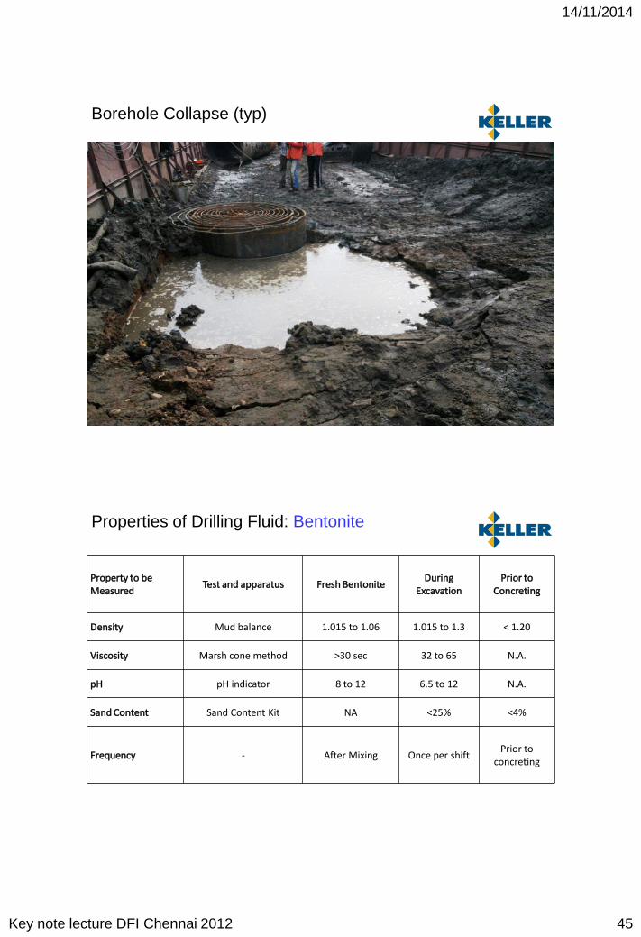
Borehole Collapse (typ)
Property to be Measured
Test and apparatus Fresh BentoniteDuring
ExcavationPrior to
Concreting
Density Mud balance 1.015 to 1.06 1.015 to 1.3 < 1.20
Viscosity Marsh cone method >30 sec 32 to 65 N.A.
pH pH indicator 8 to 12 6.5 to 12 N.A.
Sand Content Sand Content Kit NA <25% <4%
Frequency - After Mixing Once per shiftPrior to
concreting
Properties of Drilling Fluid: Bentonite
14/11/2014
Key note lecture DFI Chennai 2012 46
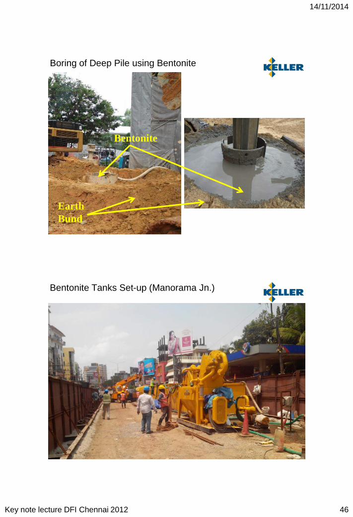
Earth Bund
Bentonite
Boring of Deep Pile using Bentonite
Bentonite Tanks Set-up (Manorama Jn.)

14/11/2014
Key note lecture DFI Chennai 2012 47
Bentonite Tanks Set-up (Manorama Jn.)
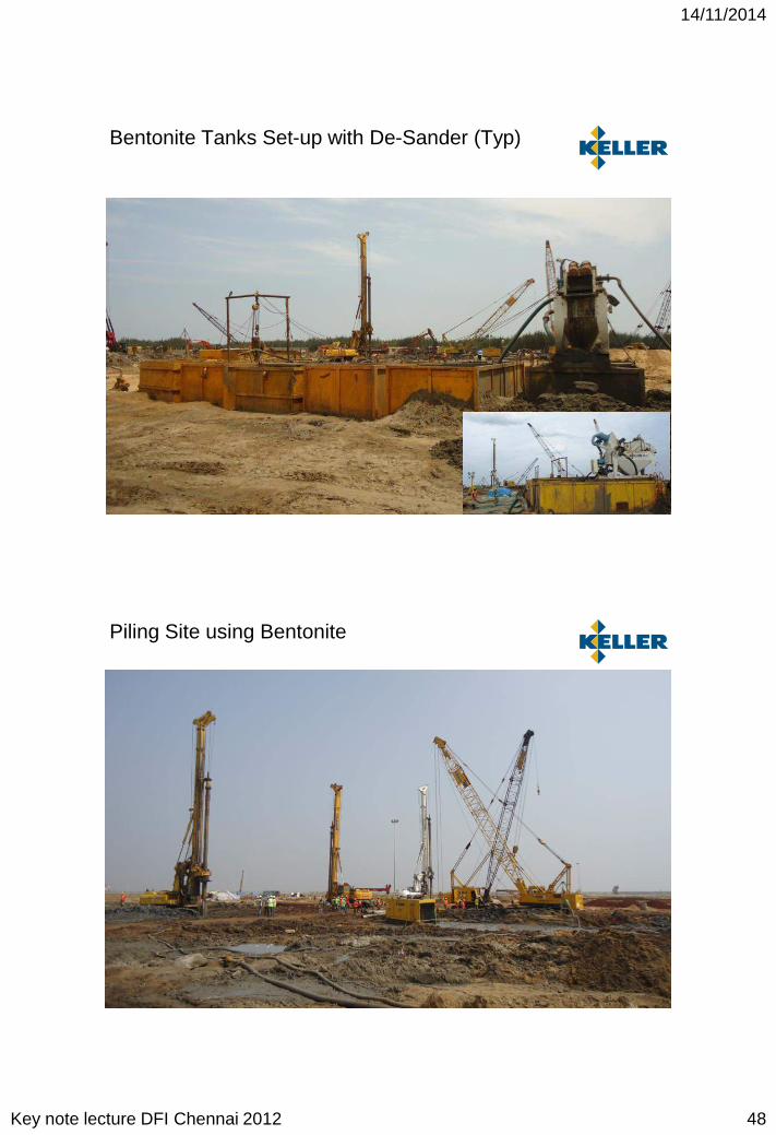
Bentonite Tanks Set-up with De-Sander
14/11/2014
Key note lecture DFI Chennai 2012 48
Bentonite Tanks Set-up with De-Sander (Typ)
Piling Site using Bentonite
14/11/2014
Key note lecture DFI Chennai 2012 49
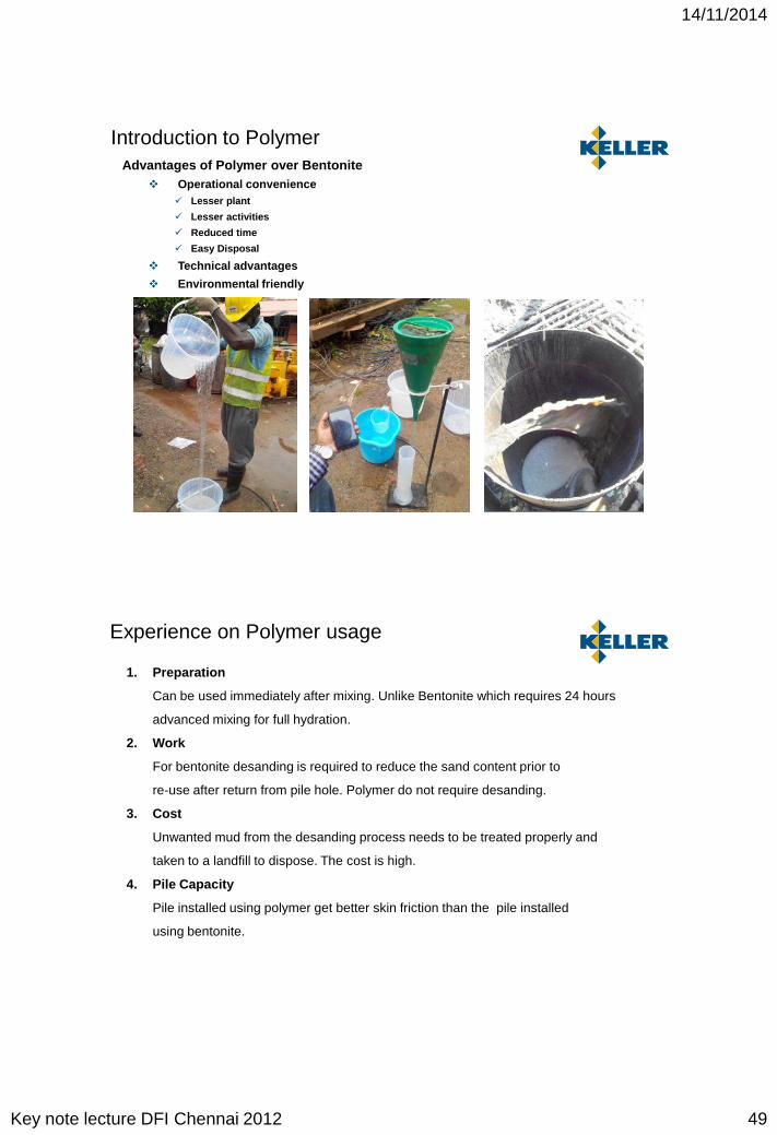
Introduction to PolymerAdvantages of Polymer over Bentonite
Operational convenience Lesser plant
Lesser activities
Reduced time
Easy Disposal
Technical advantages
Environmental friendly
1. Preparation
Can be used immediately after mixing. Unlike Bentonite which requires 24 hours
advanced mixing for full hydration.
2. Work
For bentonite desanding is required to reduce the sand content prior to
re-use after return from pile hole. Polymer do not require desanding.
3. Cost
Unwanted mud from the desanding process needs to be treated properly and
taken to a landfill to dispose. The cost is high.
4. Pile Capacity
Pile installed using polymer get better skin friction than the pile installed
using bentonite.
Experience on Polymer usage

14/11/2014
Key note lecture DFI Chennai 2012 50
Facts of usage of Polymer
Important note when using Polymer to stabilize the pile hole:
Note 1:
Study the bore hole carefully. Make sure that there is no loose sand or running sand. These
loose sand layer must be seal off by temporary casing. If these loose sand layer cannot be
sealed off by temporary casing, do not use polymer. Switch to use Bentonite.
Note 2:
Set up the Silo, square tank and mixer based on standard layout. Always make provisions to
switch to Bentonite in case the soil report are inaccurate. There may be loose sand at depths
which is difficult to be sealed off by temporary casing. Always make provision to add desander.
Note 3:
FOR THE PURPOSE OF PREVENTING COLLAPSE , BENTONITE IS BETTER THAN
POLYMER.
Property to be Measured
Test and apparatus Fresh Polymer During Excavation Prior to Concreting
Viscosity Marsh Cone Method 32 – 60 sec 40 – 60 sec N.A
Density Mud balance 1.02 to 1.06 1.02 to 1.15 < 1.25
pH pH indicator 8 to 12 8 to 12 N.A
Sand Content Sand Content Kit N.A N.A < 4 %
Properties of Drilling Fluid: Polymer

14/11/2014
Key note lecture DFI Chennai 2012 51
Polymer Mixing Flow Diagram
Mixing Plant & Silos (Singapore)

14/11/2014
Key note lecture DFI Chennai 2012 52
Mixing Plant & Tanks (India)
Boring Operation using Polymer

14/11/2014
Key note lecture DFI Chennai 2012 53
Kochi Metro (Polymer Bund Set up)
Mixing Plant & Tanks (Kochi)

14/11/2014
Key note lecture DFI Chennai 2012 54
Kochi Metro (Polymer Bund Set up)
Kochi Metro (bottom cleaning)

14/11/2014
Key note lecture DFI Chennai 2012 55
Key Factor: Reliable Soil Investigation…..!!!!!
• Reliable soil data is must to OPTIMIZE appropriate foundation alternatives
• Advanced investigation techniques such as ECPTs shall be adopted to obtain relevant soil data over the project area along with few confirmatory BHs
Cost Effective Alternate Solutions
• Choice of foundation technique to suit the project specifications• Heavy Foundations such as BCIS Piles
• Shallow Foundations (Innovative technologies to suit the project boundary conditions e.g. dry VR Techniques using bottom-feed method)
• Appropriate GI techniques shall be adopted for Earthquake Prone Regions (Liquefaction Mitigation)
• Reliable Soil Investigation + Design + Testing
• Seepage Control Measures (Grouting Techniques)
• Strut-free Excavation Supporting System (Ground Anchors)
14/11/2014
Key note lecture DFI Chennai 2012 56
Summary
• Technical Expertise will play an important role in execution of foundations (esp. for Deep Bored Piles).
• Execution of Deep Bored Piles requires state-of-the-art process . Operational Excellence with best practices deliverers the high quality whilst ensuring peak productivity.
• International standard of practices using latest equipment ensures the required Speed of Execution beneficial for early completion of project.
• Design & Build Expertise will ensure savings in Cost & Time for the investor. Also ensures, implementation of latest techniques in foundation construction.
• Safety goal of zero accidents is possible with dedicated safety systems and motivated leadership.
Thank you for your attention………
www.kellerindia.com

14/11/2014
Key note lecture DFI Chennai 2012 57
Bored Cast In-Situ Pile Foundations