gravity pipeline presentation - sep 2013
TRANSCRIPT

7/23/2019 Gravity Pipeline Presentation - Sep 2013
http://slidepdf.com/reader/full/gravity-pipeline-presentation-sep-2013 1/17
1
Gravity pipeline
1. Specific flow2. Partial flow
3. Boundary cases
4. Air blockage5. Practical exercise
7/23/2019 Gravity Pipeline Presentation - Sep 2013
http://slidepdf.com/reader/full/gravity-pipeline-presentation-sep-2013 2/17
2
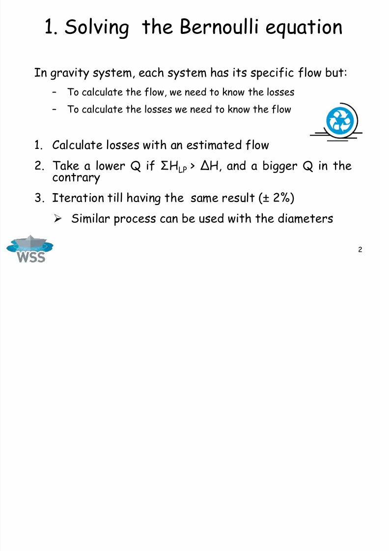
1. Solving the Bernoulli equation
In gravity system, each system has its specific flow but:
– To calculate the flow, we need to know the losses
– To calculate the losses we need to know the flow
1. Calculate losses with an estimated flow
2. Take a lower Q if ΣHLP > ΔH, and a bigger Q in thecontrary
3. Iteration till having the same result (±
2%) Similar process can be used with the diameters
7/23/2019 Gravity Pipeline Presentation - Sep 2013
http://slidepdf.com/reader/full/gravity-pipeline-presentation-sep-2013 3/17
3
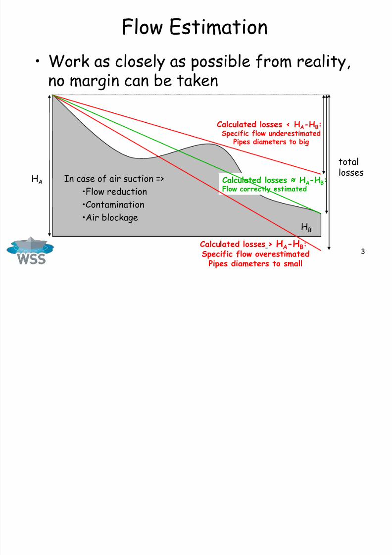
Flow Estimation
• Work as closely as possible from reality,no margin can be taken
HB
HA
Calculated losses < HA-HB:
Specific flow underestimatedPipes diameters to big
Calculated losses ≈ HA-HB:Flow correctly estimated
totallosses
Calculated losses > HA-HB:Specific flow overestimatedPipes diameters to small
In case of air suction =>
•Flow reduction
•Contamination•Air blockage

7/23/2019 Gravity Pipeline Presentation - Sep 2013
http://slidepdf.com/reader/full/gravity-pipeline-presentation-sep-2013 4/17

7/23/2019 Gravity Pipeline Presentation - Sep 2013
http://slidepdf.com/reader/full/gravity-pipeline-presentation-sep-2013 5/17
5
2 Partial flow
• Q < Qn =>Pipe not full
• Atmospheric pressure
• Energy directlydissipated
Calculated losses
Partial flowzone
Concavecase
7/23/2019 Gravity Pipeline Presentation - Sep 2013
http://slidepdf.com/reader/full/gravity-pipeline-presentation-sep-2013 6/17
6
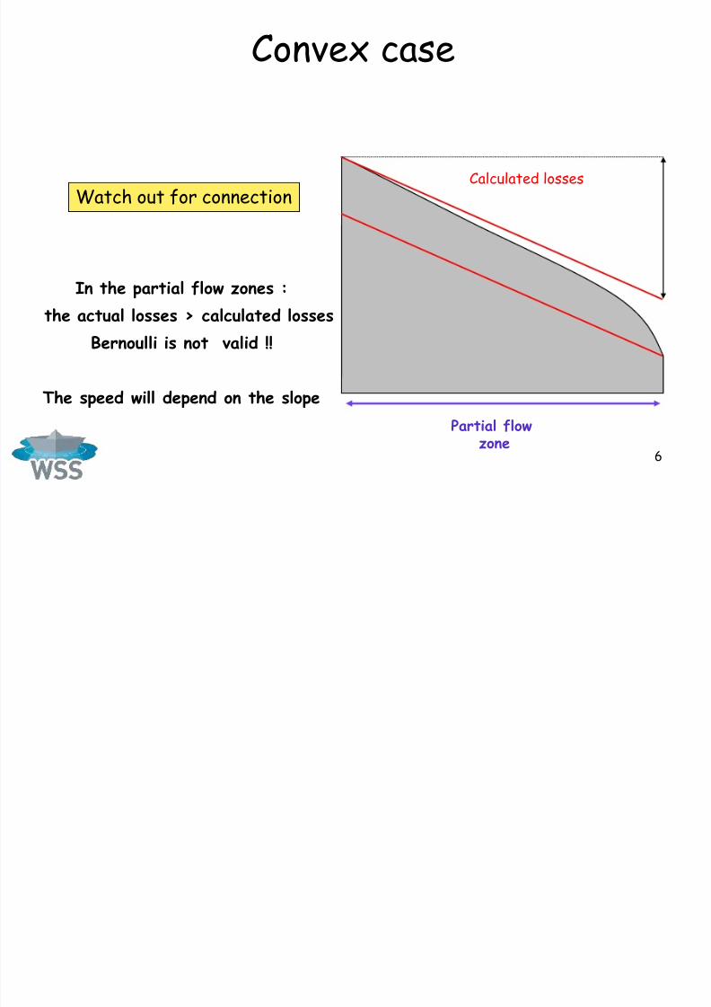
Convex case
Calculated losses
Partial flowzone
Watch out for connection
In the partial flow zones :
the actual losses > calculated losses
Bernoulli is not valid !!
The speed will depend on the slope
7/23/2019 Gravity Pipeline Presentation - Sep 2013
http://slidepdf.com/reader/full/gravity-pipeline-presentation-sep-2013 7/17
7
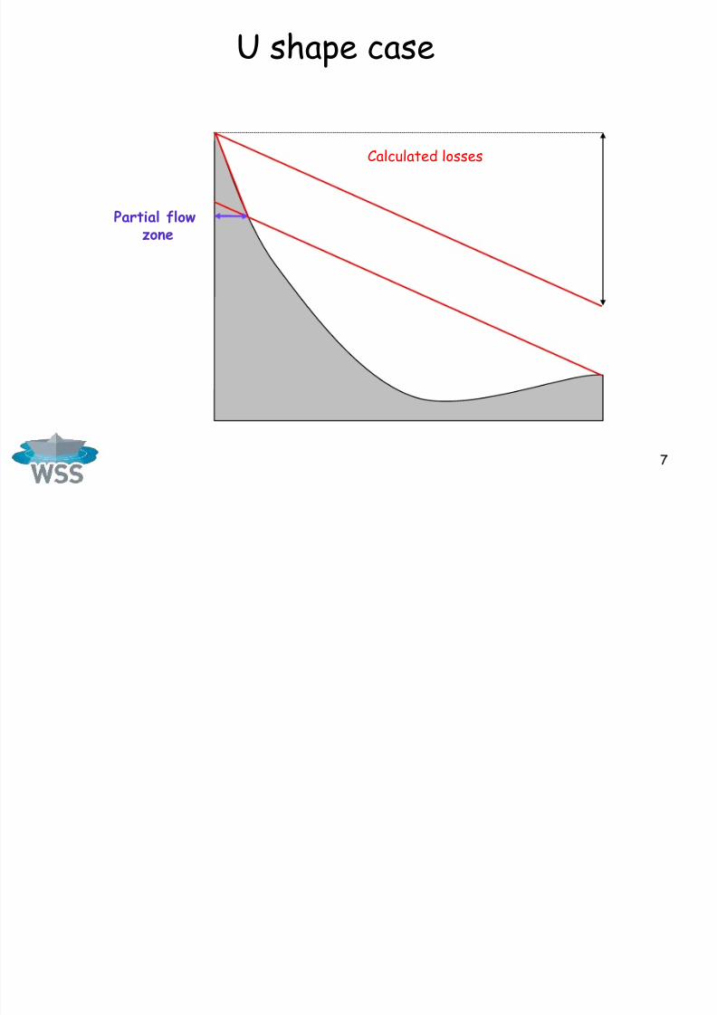
U shape case
Partial flowzone
Calculated losses

7/23/2019 Gravity Pipeline Presentation - Sep 2013
http://slidepdf.com/reader/full/gravity-pipeline-presentation-sep-2013 8/17
8
Case with a high point
• Where are we going to have partial flow ?
Calculated losses
Totalenergy

7/23/2019 Gravity Pipeline Presentation - Sep 2013
http://slidepdf.com/reader/full/gravity-pipeline-presentation-sep-2013 9/17
9
Adjust diameters to profile
To avoid depression :
• Small diameters downhill• Big diameters uphill=> Limit internal pressure
HB
Pipe with adapted diameters
Pipe with constant diameters
Pmax
7/23/2019 Gravity Pipeline Presentation - Sep 2013
http://slidepdf.com/reader/full/gravity-pipeline-presentation-sep-2013 10/17
10
0
100
200
300
400
500
0.6 1 10 100
Flow [l/s]
D i a m e t e r [ m ]
0
2
4
6
8
10
S l o p e [ ‰ ]
Diameter max
Slope min
2 3 4 5 6 7 8 20 30 40 50 70
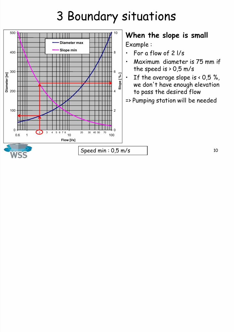
3 Boundary situations
Speed min : 0,5 m/s
When the slope is smallExample :
• For a flow of 2 l/s
• Maximum diameter is 75 mm ifthe speed is > 0,5 m/s
• If the average slope is < 0,5 %,we don't have enough elevationto pass the desired flow
=> Pumping station will be needed

7/23/2019 Gravity Pipeline Presentation - Sep 2013
http://slidepdf.com/reader/full/gravity-pipeline-presentation-sep-2013 11/17
11
Boundary situations
Velocity max : 3 m/s
When it is steepExample :
• For a flow of 2 l/s
• The minimum diameter is30mm if we want to have avelocity < 3 m/s
• If the average slope is > 45 %,the height will be too much tobe dissipated with linearfriction losses from pipes.
In this case, singular losses
should be added to limit thewater velocity
0
50
100
150
200
0.6 1 10 100
Flow [l/s]
D i a
m e t e r [ m ]
0
25
50
75
100
S l o p e [ % ]
Diameter min
Slope max
2 3 4 5 6 7 8 20 30 40 50 70
7/23/2019 Gravity Pipeline Presentation - Sep 2013
http://slidepdf.com/reader/full/gravity-pipeline-presentation-sep-2013 12/17
12
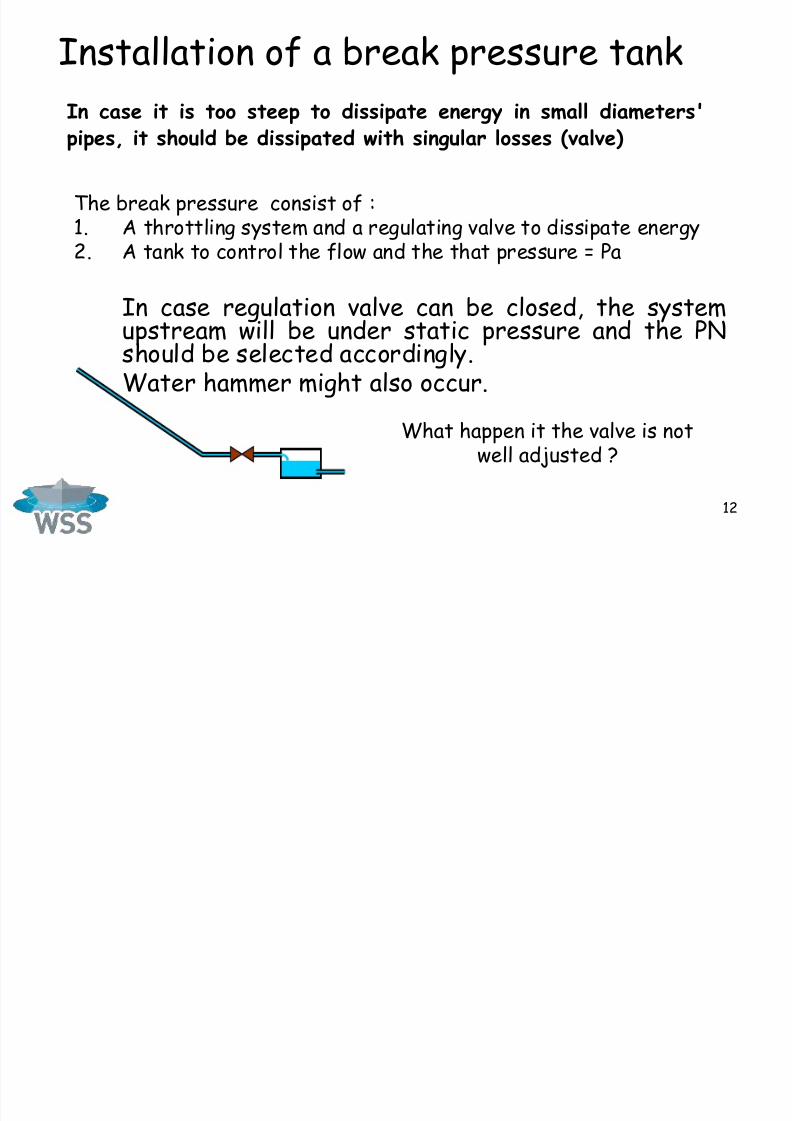
Installation of a break pressure tank
The break pressure consist of :1. A throttling system and a regulating valve to dissipate energy2. A tank to control the flow and the that pressure = Pa
In case regulation valve can be closed, the systemupstream will be under static pressure and the PNshould be selected accordingly.Water hammer might also occur.
In case it is too steep to dissipate energy in small diameters'
pipes, it should be dissipated with singular losses (valve)
What happen it the valve is notwell adjusted ?

7/23/2019 Gravity Pipeline Presentation - Sep 2013
http://slidepdf.com/reader/full/gravity-pipeline-presentation-sep-2013 13/17
13
Adjust the flowGlobe valveGate valve
Not to be used ! Correct

7/23/2019 Gravity Pipeline Presentation - Sep 2013
http://slidepdf.com/reader/full/gravity-pipeline-presentation-sep-2013 14/17
14
4 Air blockage
• Problem during
commissioning• If flow happen, air will
be absorbed• Identified the critical
sections (BC & DE)• Solution :
– Air valve, tap, Tee,– Fill in with water slowly– Pumping at the spring
Tank
Spring
> 10 meters
No risk of air blockage
Tank
Spring
Risk of air blockage
+A
+B
+C
+D +E
+
B'

7/23/2019 Gravity Pipeline Presentation - Sep 2013
http://slidepdf.com/reader/full/gravity-pipeline-presentation-sep-2013 15/17
15
Air blockageCritical section : BC
small pipes B'Clarge pipes BB'Blockage if H1+H2 > H tot
Tank
Spring
H tot
H1
H2
+B
+C
+B'
7/23/2019 Gravity Pipeline Presentation - Sep 2013
http://slidepdf.com/reader/full/gravity-pipeline-presentation-sep-2013 16/17
16
Always target optimum,no "safe side"
• Over design– Cost
– Sedimentation
– Water quality– Air blockage
– Risk of depressure
• Under design– Insufficient flow
– Erosion
– Water hammer

7/23/2019 Gravity Pipeline Presentation - Sep 2013
http://slidepdf.com/reader/full/gravity-pipeline-presentation-sep-2013 17/17
17
Tool Gravity Pipe• With function
"Editer Ouvrage",enter all points• Update with the
window or directlyin the spread sheet
• Adjust diametersto have a goodpressure profile
• Possibility to havebranches
• Version in English is
planned