grain-orientation related surface effects on ... · grain-orientation related surface effects on...
TRANSCRIPT
Journal of Materials Science and Engineering B 6 (7-8) (2016) 161-168 doi: 10.17265/2161-6221/2016.7-8.001
Grain-Orientation Related Surface Effects on
Polycrystalline Tungsten Caused by Mechanical
Polishing and Etching
Inge Uytdenhouwen1, Willy Vandermeulen1*, Yevhen Zayachuk2 and Raymond Kemps3
1. Belgian Nuclear Research Centre, SCK.CEN, Boeretang 200, 2400 Mol, Belgium
2. Department of Materials, University of Oxford, Parks Road, Oxford OX1 3PH, UK and Culham Centre for Fusion Energy,
Culham Science Centre, Abingdon OX14 3DB, UK
3. Flemish Institute for Technological Research, Vito, Boeretang 200, 2400 Mol, Belgium
Abstract: The problem of obtaining a smoothly polished planar surface on polycrystalline tungsten is important for its applications as substrate in electronics as well as for preparing surfaces for research related to fusion reactor applications. In the latter case the classical metallographic polishing methods, using diamond abrasives, are generally used to prepare surfaces for the study of the interaction of the fusion plasma with tungsten. During a short study of the mechanical polishing of pure tungsten, it was observed that the material removal was different from grain to grain, giving rise to a non-planar surface. By polishing with 3 µm diamond grit as an intermediate step a dot pattern develops which outlines the grain structure. The dots were shown to consist of small cracks. On further polishing with 1 µm diamond the dot pattern disappears. However, it re-appears when polishing again with 3 µm grit. Apparently these effects are caused by the orientation dependent mechanical interaction between the 3 µm diamond particles and the tungsten crystal lattice. The coincidence of the surface dot patterns and the underlying grain structure could be clearly demonstrated by etching. Etching also demonstrated the presence of plastic deformation to a depth of the order of 4 µm. It is advised to further examine the sub-surface deformation layer in view of its effect on deuterium and tritium storage.
Key words: Tungsten, polishing, anisotropy, contact fatigue, sub surface deformation, tritium retention.
1. Introduction
Polishing of tungsten is important for its use as
substrate in electronic applications as well as for its
use as the plasma facing material in future fusion
reactors [1-5]. A considerable number of studies,
mainly for the field of electronics, has been devoted to
the effect of the polishing parameters. Very flat
surfaces can be obtained by the so called
chemical-mechanical polishing methods in which an
oxidizing chemical reagent is added to a diamond
suspension [5-8]. Recently it has been demonstrated
that chemical-mechanical polishing leads to a
considerable reduction of the surface layer affected by
plastic deformation [6]. Much less polishing *Corresponding author: Willy Vandermeulen, visiting scientist, research fields: metals and ceramics properties.
studies aiming at the needs of the fusion field are
available. The selection of tungsten for this
application is based on its high melting point and high
atomic mass. However, during exposure to the fusion
plasma, deuterium (D) and tritium (T) atoms are
implanted in a surface layer of only a few 10 nm but
even at relatively low temperatures these atoms
diffuse to depths of several µm leading to a
prohibitive storage of radioactive T atoms. This so
called T-retention may cause serious safety problems.
Furthermore, both D and T lead to surface
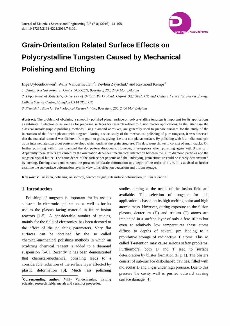
deterioration by blister formation (Fig. 1). The blisters
consist of sub-surface disk-shaped cavities, filled with
molecular D and T gas under high pressure. Due to this
pressure the cavity wall is pushed outward causing
surface damage [4].
D DAVID PUBLISHING
Grain-Orientation Related Surface Effects on Polycrystalline Tungsten Caused by Mechanical Polishing and Etching
162
Fig. 1 Mechanically polished tungsten after exposure to a hydrogen plasma. Blister formation in upper right grain. No blisters in left grain.
It is clear that D/T retention and blister formation in
tungsten are important issues. Therefore, they are
extensively studied mostly by exposure to a hydrogen
or deuterium plasma. Since the surface layer involved
is only of the order of micrometre, the surface
preparation method of the specimens used for
implantation tests plays an important role. Usually
mechanical polishing is used until a mirror aspect is
obtained, but of course this does not guarantee that the
structure of the near-surface layer is unaffected.
Unfortunately, the laboratories which study the
application of tungsten in fusion reactors do not
always have the possibility of chemical- mechanical
polishing. Moreover, surface oxidation by chemical
polishing could also have an unwanted effect on the
surface condition. Therefore, for fusion research,
tungsten is often polished with conventional
metallographic equipment [1, 2].
The short study presented in this article was
performed mainly with respect to the field of fusion
research in order to draw attention to phenomena
which either occur at intermediate polishing steps, but
are no more visible after the final step, or which
become only apparent after etching. These
observations strongly point at the existence of a
sub-surface dislocation structure and a surface
passivating layer, both resulting from the specimen
preparation.
2. Experimental
The tungsten used in this study was provided by
Plansee in two conditions: recrystallized and forged,
with HV20 hardness of 500 and 600. The grain size of
the recrystallized material was of the order of 250 µm.
Small samples of 3 by 1.5 mm were mounted
separately in Polyfast blocks with a diameter of 25
mm. For grinding, SiC paper 1200 was used.
Polishing was done with diamond suspensions of 3
and 1 µm. The polishing cloth was Struers NAP but
DUR was used with the same results. Grinding and
polishing was done with Struers TegraPol-11
equipment at a speed of 150 rpm and a force of 15 N.
Grinding was done under water flow. For polishing
the cloth was kept moist with water.
Grain-Orientation Related Surface Effects on Polycrystalline Tungsten Caused by Mechanical Polishing and Etching
163
The basic polishing sequence consisted of:
Grinding while rotating the specimen, on 1200
grit paper followed by short (10 sec) manual grinding
without rotation to obtain parallel lines. These
uniform lines make it easier to follow the subsequent
diamond polishing. After grinding, a Vickers hardness
indentation was made as a location marker to follow
the evolution of the surface appearance.
Polishing while rotating the specimen, with 3 µm
grit polycrystalline diamond for times up to 20 min
while rotating the specimen, with 1 µm grit
polycrystalline diamond for times up to 15 min
optional: etching during 20 s with 4 parts
H2O-25%NH3 and 1 part H2O2 to reveal the tungsten
grains.
A limited amount of polishing was done with a load
of 50 N, on a specimen of 15 by 15 mm in order to
obtain a lower load/unit surface ratio.
The evolution of the surface condition was
examined with a Leica DMLM microscope. Since the
contrast on normally focused images was very weak it
had to be enhanced by under- or over-focusing. These
pictures were then further treated with
Zeiss-Axiocam-MRc5 software.
3. Results
Using the basic preparation procedure described
above it was found by optical microscopy (OM) that a
satisfactory surface finish could be obtained for forged
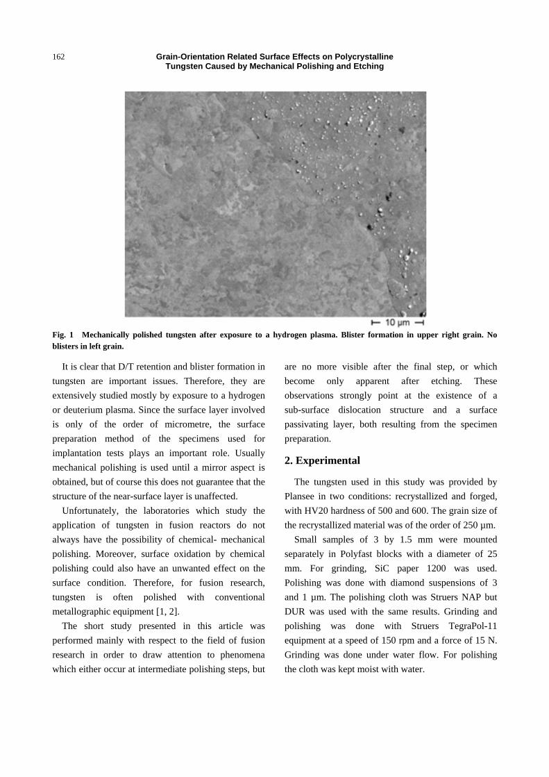
as well as for recrystallized tungsten. Fig. 2a shows an
example of such a surface. It is smooth along the
horizontal center zone while at the upper and lower
edges some non-smooth regions are probably due to
edge effect. In the following, attention will only be
paid to the central zone.
Two phenomena will be described. The first
consists of surface relief caused by the material
removal rate being different from grain to grain. The
second is the occurrence of surface cracking observed
during the intermediate polishing step with 3 µm
diamond grit. Both are illustrated and discussed for
the recrystallized specimen. The behavior for the
forged condition was found to be the same.
To avoid as much as possible pre-existing damage,
the preparation was repeated after a preceding
polishing sequence up to 1 µm (Fig. 2a). This surface
was then ground without rotation on paper 1200 and a
HV20 indentation was made for reference (Fig. 2b).
Due to this grinding a previous indention (marked A,
visible on the left side of Fig. 2c), decreased in size
due to removal of surface material. The size decrease
corresponds to the removal of about 30 µm.
The ground surface was then polished for 20 min
with 3 µm grit diamond (Figs. 2c and 2d). It can be
seen that the grains have become visible because each
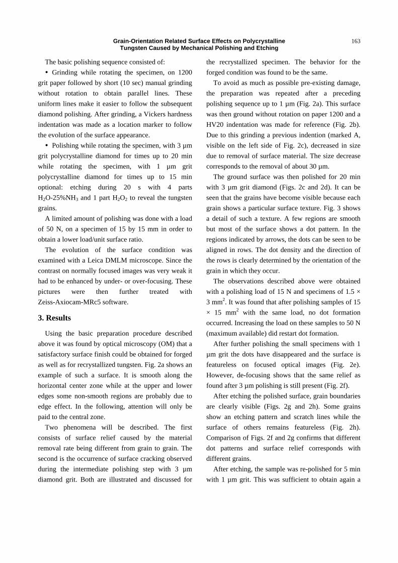
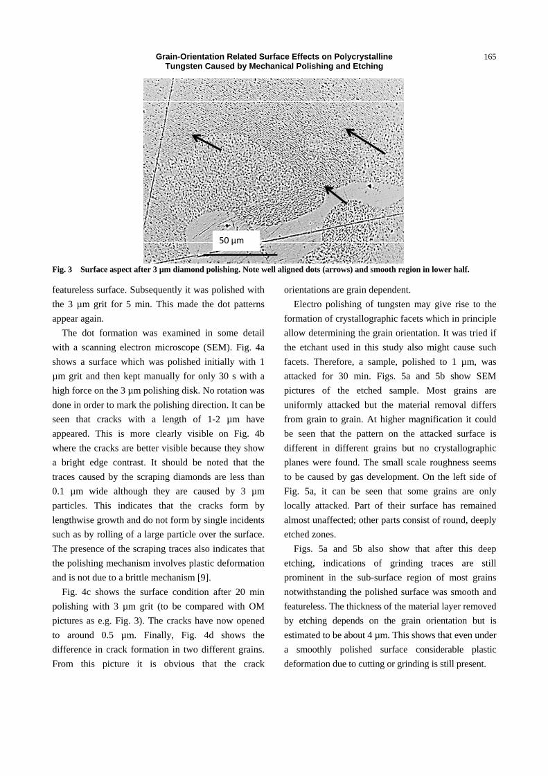
grain shows a particular surface texture. Fig. 3 shows
a detail of such a texture. A few regions are smooth
but most of the surface shows a dot pattern. In the
regions indicated by arrows, the dots can be seen to be
aligned in rows. The dot density and the direction of
the rows is clearly determined by the orientation of the
grain in which they occur.
The observations described above were obtained
with a polishing load of 15 N and specimens of 1.5 ×
3 mm2. It was found that after polishing samples of 15
× 15 mm2 with the same load, no dot formation
occurred. Increasing the load on these samples to 50 N
(maximum available) did restart dot formation.
After further polishing the small specimens with 1
µm grit the dots have disappeared and the surface is
featureless on focused optical images (Fig. 2e).
However, de-focusing shows that the same relief as
found after 3 µm polishing is still present (Fig. 2f).
After etching the polished surface, grain boundaries
are clearly visible (Figs. 2g and 2h). Some grains
show an etching pattern and scratch lines while the
surface of others remains featureless (Fig. 2h).
Comparison of Figs. 2f and 2g confirms that different
dot patterns and surface relief corresponds with
different grains.
After etching, the sample was re-polished for 5 min
with 1 µm grit. This was sufficient to obtain again a
Grain-Orientation Related Surface Effects on Polycrystalline Tungsten Caused by Mechanical Polishing and Etching
164
Fig. 2 Evolution of surface upon grinding, polishing and etching: (a) starting condition, (b) manually ground without rotation, (c) polished 20 min with 3 µm diamond (d) same, detail of the HV. Note extensive dot formation (e) polished with 1 µm diamond, image focused (f) same, over-focused (g) etched. Note boundary and surface attack of most grains and (h) same, detail of HV.
Grain-Orientation Related Surface Effects on Polycrystalline Tungsten Caused by Mechanical Polishing and Etching
165
50 µm50 µm
Fig. 3 Surface aspect after 3 µm diamond polishing. Note well aligned dots (arrows) and smooth region in lower half.
featureless surface. Subsequently it was polished with
the 3 µm grit for 5 min. This made the dot patterns
appear again.
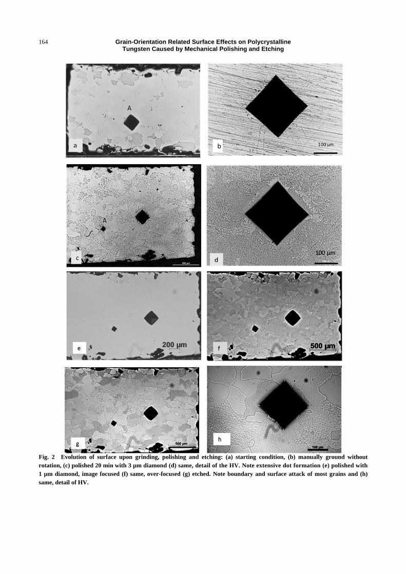
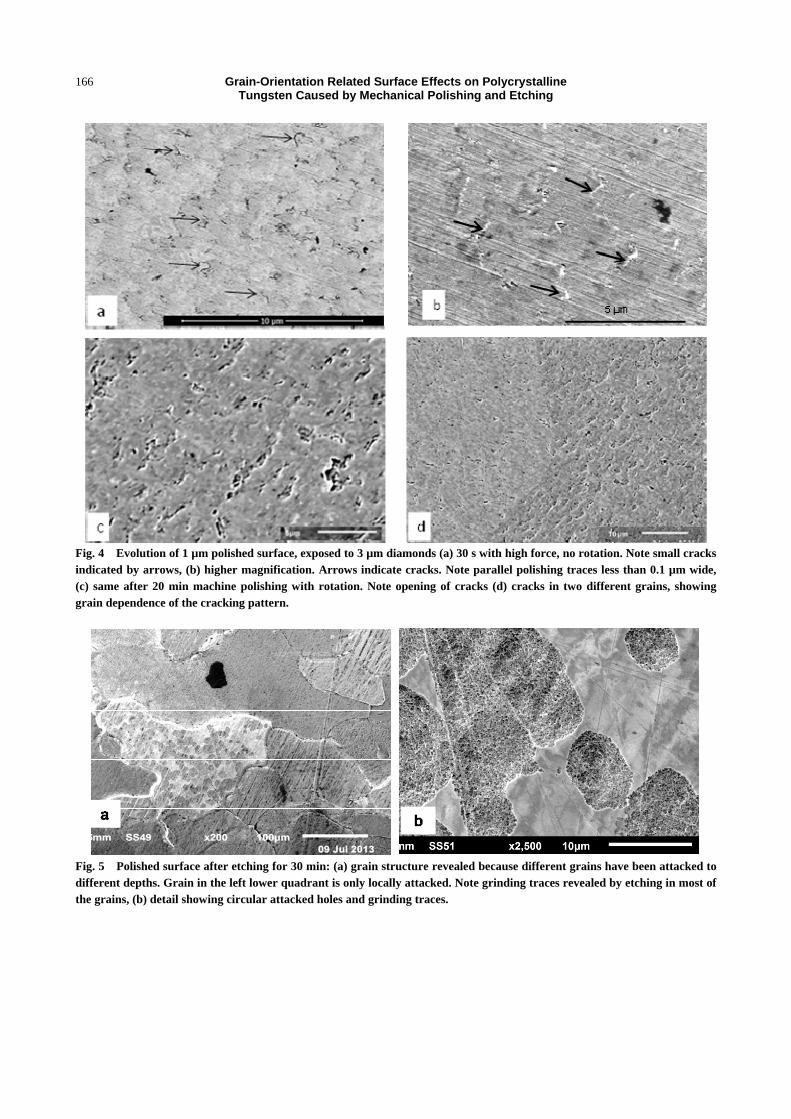
The dot formation was examined in some detail
with a scanning electron microscope (SEM). Fig. 4a
shows a surface which was polished initially with 1
µm grit and then kept manually for only 30 s with a
high force on the 3 µm polishing disk. No rotation was
done in order to mark the polishing direction. It can be
seen that cracks with a length of 1-2 µm have
appeared. This is more clearly visible on Fig. 4b
where the cracks are better visible because they show
a bright edge contrast. It should be noted that the
traces caused by the scraping diamonds are less than
0.1 µm wide although they are caused by 3 µm
particles. This indicates that the cracks form by
lengthwise growth and do not form by single incidents
such as by rolling of a large particle over the surface.
The presence of the scraping traces also indicates that
the polishing mechanism involves plastic deformation
and is not due to a brittle mechanism [9].
Fig. 4c shows the surface condition after 20 min
polishing with 3 µm grit (to be compared with OM
pictures as e.g. Fig. 3). The cracks have now opened
to around 0.5 µm. Finally, Fig. 4d shows the
difference in crack formation in two different grains.
From this picture it is obvious that the crack
orientations are grain dependent.
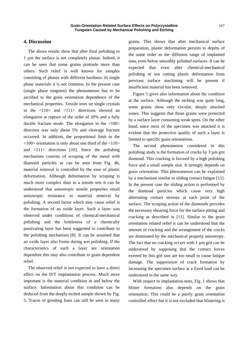
Electro polishing of tungsten may give rise to the
formation of crystallographic facets which in principle
allow determining the grain orientation. It was tried if
the etchant used in this study also might cause such
facets. Therefore, a sample, polished to 1 µm, was
attacked for 30 min. Figs. 5a and 5b show SEM
pictures of the etched sample. Most grains are
uniformly attacked but the material removal differs
from grain to grain. At higher magnification it could
be seen that the pattern on the attacked surface is
different in different grains but no crystallographic
planes were found. The small scale roughness seems
to be caused by gas development. On the left side of
Fig. 5a, it can be seen that some grains are only
locally attacked. Part of their surface has remained
almost unaffected; other parts consist of round, deeply
etched zones.
Figs. 5a and 5b also show that after this deep
etching, indications of grinding traces are still
prominent in the sub-surface region of most grains
notwithstanding the polished surface was smooth and
featureless. The thickness of the material layer removed
by etching depends on the grain orientation but is
estimated to be about 4 µm. This shows that even under
a smoothly polished surface considerable plastic
deformation due to cutting or grinding is still present.
Grain-Orientation Related Surface Effects on Polycrystalline Tungsten Caused by Mechanical Polishing and Etching
166
Fig. 4 Evolution of 1 µm polished surface, exposed to 3 µm diamonds (a) 30 s with high force, no rotation. Note small cracks indicated by arrows, (b) higher magnification. Arrows indicate cracks. Note parallel polishing traces less than 0.1 µm wide, (c) same after 20 min machine polishing with rotation. Note opening of cracks (d) cracks in two different grains, showing grain dependence of the cracking pattern.
Fig. 5 Polished surface after etching for 30 min: (a) grain structure revealed because different grains have been attacked to different depths. Grain in the left lower quadrant is only locally attacked. Note grinding traces revealed by etching in most of the grains, (b) detail showing circular attacked holes and grinding traces.
Grain-Orientation Related Surface Effects on Polycrystalline Tungsten Caused by Mechanical Polishing and Etching
167
4. Discussion
The above results show that after final polishing to
1 µm the surface is not completely planar. Indeed, it
can be seen that some grains protrude more than
others. Such relief is well known for samples
consisting of phases with different hardness. In single
phase materials it is not common. In the present case
(single phase tungsten) the phenomenon has to be
ascribed to the grain orientation dependence of the
mechanical properties. Tensile tests on single crystals
in the <110> and <111> directions showed an
elongation at rupture of the order of 20% and a fully
ductile fracture mode. The elongation in the <100>
direction was only about 5% and cleavage fracture
occurred. In addition, the proportional limit in the
<100> orientation is only about one third of the <110>
and <111> directions [10]. Since the polishing
mechanism consists of scraping of the metal with
diamond particles as can be seen from Fig. 4b,
material removal is controlled by the ease of plastic
deformation. Although deformation by scraping is
much more complex than in a tensile test it can be
understood that anisotropic tensile properties entail
anisotropic resistance to material removal by
polishing. A second factor which may cause relief is
the formation of an oxide layer. Such a layer was
observed under conditions of chemical-mechanical
polishing and the brittleness of a chemically
passivating layer has been suggested to contribute to
the polishing mechanism [8]. It can be assumed that
an oxide layer also forms during wet polishing. If the
characteristics of such a layer are orientation
dependent this may also contribute to grain dependent
relief.
The observed relief is not expected to have a direct
effect on the D/T implantation process. Much more
important is the material condition at and below the
surface. Information about this condition can be
deduced from the deeply etched sample shown by Fig.
5. Traces of grinding lines can still be seen in many
grains. This shows that after mechanical surface
preparation, plastic deformation persists to depths of
the same order as the diffusion range of implanted
ions, even below smoothly polished surfaces. It can be
expected that even after chemical-mechanical
polishing or ion cutting plastic deformation from
previous surface machining will be present if
insufficient material has been removed.
Figure 5 gives also information about the condition
at the surface. Although the etching was quite long,
some grains show only circular, deeply attacked
zones. This suggests that those grains were protected
by a surface layer containing weak spots. On the other
hand, since most of the specimen was attacked it is
evident that the protective quality of such a layer is
limited to specific grain orientations.
The second phenomenon considered in this
polishing study is the formation of cracks by 3 µm grit
diamond. This cracking is favored by a high polishing
force and a small sample size. It strongly depends on
grain orientation. This phenomenon can be explained
by a mechanism similar to sliding contact fatigue [11].
In the present case the sliding action is performed by
the diamond particles which cause very high
alternating contact stresses at each point of the
surface. The scraping action of the diamonds provides
the necessary shearing force for the surface pitting and
cracking as described in [11]. Similar to the grain
orientation related relief it can be understood that the
amount of cracking and the arrangement of the cracks
are dominated by the mechanical property anisotropy.
The fact that no cracking occurs with 1 µm grit can be
understood by supposing that the contact forces
exerted by this grit size are too small to cause fatigue
damage. The suppression of crack formation by
increasing the specimen surface at a fixed load can be
understood in the same way.
With respect to implantation tests, Fig. 1 shows that
blister formation also depends on the grain
orientation. This could be a purely grain orientation
controlled effect but it is not excluded that blistering is
Grain-Orientation Related Surface Effects on Polycrystalline Tungsten Caused by Mechanical Polishing and Etching
168
also affected by the surface and sub surface defect
state. Therefore, careful characterization of this state
has to be strongly recommended for H/D/T
implantation and retention studies.
5. Conclusions
The surface relief found on mechanically polished
tungsten is explained by the anisotropy of the
mechanical properties. The formation of an orientation
dependent oxide layer might also contribute to the
relief formation.
The grain dependent pattern of surface cracks,
caused by polishing with 3 µm grit diamond, is caused
by sliding contact fatigue under a high specific loading.
Both, the occurrence of polishing marks on deeply
etched surfaces and the observation of fatigue
deformation, are indications that plastic deformation
due to the sample preparation is present below
apparently good polished surfaces. This shows the
necessity of a careful characterization of the surface
and sub-surface defect structure of specimens used for
H/D/T retention studies.
References
[1] Zayachuk, Y., ‘t Hoen, M. H. J., Zeijlmans van
Emmighoven, P. A., Terentyev, D., Uytdenhouwen, I.
and van Oost, G. 2013. “Surface Modification of
Tungsten and Tungsten-Tantalum Alloys Exposed to
High-Flux Deuterium Plasma and its Impact on
Deuterium Retention.” Nucl. Fusion 53: 0130131-7.
[2] Alimov, V. Kh., Tyburska-Puschel, B., Lindig, S.,
Hatano, Y., Balden, M. and Rith, J. et al. 2012. “Temperature Dependence of Surface Morphology and Deuterium Retention in Polycrystalline ITER-Grade Tungsten Exposed to Low-Energy, High-Flux D Plasma.” J. Nucl. Mater. 420: 519-24.
[3] Manhard, A., Matern, G. and Balden, M. 2013. “A Step-by-Step Analysis of the Polishing Process for Tungsten Specimens” Pract. Metallogr. 50: 5-16.
[4] Jia, Y. Z., De Temmerman, G., Luo, G.-N., Xu, H. Y., Li,
C. and Fu, B. Q. et al. 2015. “Surface Morphology and
Deuterium Retention in Tungsten Exposed to High Flux
D Plasma at High Temperatures” J. Nucl. Mater. 457:
213-9.
[5] Stojadinovic, J. 2009. “Chemical-Mechanical Polishing
of Tungsten: Electrochemical and Tribo-Corrosion
Approach.” Ph.D. thesis, Federal Polytechnical School of
Lausanne, Switserland.
[6] Bielmann, M., Mahajan, U. and Singh, R. K. 1999.
“Effect of Particle Size during Tungsten Chemical
Mechanical Polishing.” Electrochemical and Solid-State
Letters 2: 401-3.
[7] Larsen-Basse, J. and Liang, H. 1999. “Probable Role of
Abrasion in Chemo-Mechanical Polishing of Tungsten.”
Wear 233-235: 647-54.
[8] Lim, M. S., van der Heide, P. A. W., Perry, S. S.,
Galloway, H. C. and Koeck, C. K. 2004. “Microscopic
Investigations of Chemo-Mechanical Polishing of
Tungsten.” Thin Solid Films 457: 346-53.
[9] Samuels, L. E. 1982. “Metallographic Polishing by
Mechanical Methods.” In American Society for Metals.
Chap.7: Brittle Materials, Metals Park, Ohio.
[10] Beardmore, P. and Hull, D. 1965. “Deformation and
Fracture of Tungsten Single Crystals”. J. Less-Common
Metals 9: 168-80.
[11] Sadeghi, F., Jalalahmadi, B., Slack, T. S., Raje, N. and
Arakere, N. K. 2009. “A Review of Rolling Contact
Fatigue.” J. of Tribology 131: 0414031-15.