gp 30-85 fire and gas detection
DESCRIPTION
Fire and Gas Detection guidelines by BPTRANSCRIPT

Guidance on Practice for Fire and Gas Detection
GP 30-85
BP GROUPENGINEERING TECHNICAL PRACTICES
Document No. GP 30-85
Applicability Group
Date 29 January 2003

29 January 2003 GP 30-85Guidance on Practice for Fire and Gas Detection
Foreword
This is the first issue of Engineering Technical Practice (ETP) BP GP 30-85. This Guidance on Practice (GP) is based on parts of heritage documents from the merged BP companies as follows:
Amoco
A PS-F&GD-00-E Process Safety—F&G Detection and Alarm Equipment—Engineering Specification, May 1997.
A PS-F&GD-00-G Process Safety—F&G Detection and Alarm Equipment—Guide, May 1997.
A PS-F&GD-FDA-P Process Safety—F&G Detection and Alarm Equipment—Fire Detection and Alarms—Supply Specification, May 1997.
A PS-F&GD-GD&A-P Process Safety—F&G Detection and Alarm Equipment—Gas Detection and Alarms—Supply Specification, May 1997.
BP (pre 1999)
RP 30-7 Design Philosophy for Fire and Gas Detection and Control Systems, February 1994.
GS 130-10 Guidance for Specification 130-10, Specification for the Supply of Fire & Gas Systems, January 1994.
BP Exploration
SPR/G/97/005 Guidance on F&G Detection, SPR Operational Integrity Team, General Requirements, Part 1, April 1997.
SPR/G/97/005 Guidance on F&G Detection, SPR Operational Integrity Team, Setting Performance Requirements, Part 2, April 1997.
SPR/G/97/005 Guidance on F&G Detection, SPR Operational Integrity Team, Detector Specification, Part 3, July 1997.
SPR/G/97/005 Guidance on F&G Detection, SPR Operational Integrity Team, Audit & Inspection, Part 6, April 1997.
Page 2 of 45
Copyright 2002, BP Group. All rights reserved. The information contained in this document is subject to the terms and conditions of the agreement or contract under which the document was supplied to the recipient’s organization. None of the information contained in this document shall be disclosed outside the recipient’s own organization without the prior written permission of Manager, Standards, BP Group, unless the terms of such agreement or contract expressly allow.
29 January 2003 GP 30-85Guidance on Practice for Fire and Gas Detection
Table of Contents
Page
Foreword............................................................................................................................................2
1. Scope........................................................................................................................................6
2. Normative references................................................................................................................6
3. Terms and definitions................................................................................................................7
4. Symbols and abbreviations.......................................................................................................7
5. General.....................................................................................................................................8
5.1. Legislative regulations, local codes, and standards......................................................8
5.2. Safety management.......................................................................................................8
5.3. Specifier role..................................................................................................................8
5.4. Performance..................................................................................................................9
5.5. Hazards..........................................................................................................................9
6. Fire detection performance.....................................................................................................11
6.1. General........................................................................................................................11
6.2. Fire sensitivity levels fire risk analysis.........................................................................12
6.3. Fire risk categories......................................................................................................12
6.4. Area types and use......................................................................................................13
6.5. Grade definitions..........................................................................................................14
6.6. Assigning grades to hydrocarbon handling areas........................................................16
6.7. Assigning grades to nonhydrocarbon handling areas..................................................16
6.8. Assigning grade to special areas.................................................................................17
6.9. Fire detection voting....................................................................................................19
6.10. Manual fire alarm stations............................................................................................19
7. Flammable gas detection performance...................................................................................20
7.1. General........................................................................................................................20
7.2. Risk volume assessment.............................................................................................20
7.3. Gas detection control actions......................................................................................22
7.4. Gas detection voting....................................................................................................23
8. Toxic gas detection performance............................................................................................23
8.1. General........................................................................................................................23
8.2. Carbon monoxide........................................................................................................24
8.3. Carbon dioxide.............................................................................................................24
8.4. Hydrogen sulphide.......................................................................................................24
8.5. Hydrogen cyanide........................................................................................................25
8.6. Hydrogen fluoride........................................................................................................25
9. Safe havens............................................................................................................................25
10. Detector type selection...........................................................................................................25
10.1. General........................................................................................................................25
Page 3 of 45
29 January 2003 GP 30-85Guidance on Practice for Fire and Gas Detection
10.2. Flame...........................................................................................................................26
10.3. Gas..............................................................................................................................27
10.4. Heat.............................................................................................................................28
10.5. Oil mist.........................................................................................................................30
10.6. Smoke..........................................................................................................................30
11. Detector deployment...............................................................................................................32
11.1. General........................................................................................................................32
11.2. Flame...........................................................................................................................32
11.3. Gas..............................................................................................................................32
11.4. Heat.............................................................................................................................33
11.5. Oil mist.........................................................................................................................33
11.6. Smoke..........................................................................................................................33
12. Control and indicating equipment...........................................................................................33
13. Maintenance...........................................................................................................................34
14. Audit and inspection................................................................................................................34
14.1. General........................................................................................................................34
14.2. Audit criteria.................................................................................................................34
14.3. System design review..................................................................................................35
14.4. Installed equipment review..........................................................................................35
14.5. Reliability and availability review.................................................................................36
14.6. Personnel review.........................................................................................................37
Annex A (Normative) F&G detection performance record sheets....................................................38
Annex B (Normative) Test requirements for high-sensitivity smoke detection systems..................43
B.1 General...................................................................................................................................43
B.1.1 Scope...........................................................................................................................43
B.1.2 Fire simulation.............................................................................................................43
B.2 Test equipment.......................................................................................................................43
B.3 Test procedure........................................................................................................................43
Bibliography......................................................................................................................................44
List of Tables
Table 1 - Comparison of RHO and apparent flame area.................................................................10
Table 2 - Fire risk categorisation......................................................................................................13
Table 3 - Fire detection grade definitions.........................................................................................15
Table 4 - Fire detection sensitivity recommended defaults..............................................................15
Table 5 - Typical performance requirements...................................................................................16
Table 6 - Typical requirements for Grade T and Grade V................................................................17
Table 7 - Exposure limits for common toxic gases...........................................................................24
List of Figures
Page 4 of 45

29 January 2003 GP 30-85Guidance on Practice for Fire and Gas Detection
Figure 1 - Method for setting fire detection requirements................................................................45
Figure 2 - Method for setting flammable gas detection requirements..............................................46
Page 5 of 45
29 January 2003 GP 30-85Guidance on Practice for Fire and Gas Detection
1. Scope
a. This GP provides guidance on practice for fire and gas (F&G) detection for BP facilities including:
1. Required performance.
There are no recognised national or international codes or standards that cover the performance specification of F&G detection systems.
2. Selection.
3. Design.
4. Installation.
5. Operation.
6. Maintenance.
7. Audit of system designs and installations.
b. This GP does not cover detection by analysers. Refer to ETPs in ETP document category 31 for information on analysers.
2. Normative references
The following normative documents contain requirements that, through reference in this text, constitute requirements of this technical practice. For dated references, subsequent amendments to, or revisions of, any of these publications do not apply. However, parties to agreements based on this technical practice are encouraged to investigate the possibility of applying the most recent editions of the normative documents indicated below. For undated references, the latest edition of the normative document referred to applies.
BP
GP 12-60 Guidance on Practice for Hazardous Area Electrical Installations.
GP 30-45 Guidance on Practice for Human Machine Interface for Process Control.
GP 30-75 Guidance on Practice for Safety Instrumented Systems (SIS) – Management of the Safety Lifecycle.
GP 30-76 Guidance on Practice for Safety Instrumented Systems (SIS) – Development of the Process Requirements Specification.
GP 30-80 Guidance on Practice for Safety Instrumented Systems (SIS) – Implementation of the Process Requirements Specification.
GP 30-81 Guidance on Practice for Safety Instrumented Systems (SIS) – Operations and Maintenance.
GIS 30-851 Guidance on Industry Standard for Fire and Gas Detection.
British Standards Institute (BSI)
BSI BS 5839 Part 1 Fire detection and alarm systems for buildings.
International Electrotechnical Commission (IEC)
IEC 61508 Functional safety of electrical/electronic/programmable electronic safety-related systems – Parts 1 to 4.
Page 6 of 45

29 January 2003 GP 30-85Guidance on Practice for Fire and Gas Detection
National Fire Protection Association (NFPA)
NFPA 72 National Fire Alarm Code.
3. Terms and definitions
For the purposes of this GP, the following terms and definitions apply:
1ooN
One out of (1oo) the number (N) of detectors or circuits in the voting group in a specific area is in alarm.
1oo2d
One out of (1oo) the number (N, in this case N = 2) of detectors or circuits in the voting group is in alarm, and a different detector or circuit in the same voting group is in fault condition.
2ooN
Two out of (2oo) the number (N) of detectors or circuits in the voting group are in alarm.
Blockage ratio
Proportion of unobstructed area on all the boundary faces of a volume. For example, an enclosed box has a blockage ratio of 1.0.
4. Symbols and abbreviations
For the purpose of this GP, the following symbols and abbreviations apply:
BS British standard.
ESD Emergency shutdown.
FPSO Floating production, storage and offloading (vessel).
LEL Lower explosive limit.
LFL Lower flammable limit.
OD Outside diameter.
RHO Radiant heat output.
SIL Safety integrity level.
STEL Short-term exposure limit.
TWA Time weighted average.
UEL Upper explosive limit.
UFL Upper flammable limit.
VESDA Very early smoke detection apparatus. (VESDA is a registered trademark of Vision Systems. Mention of the VESDA name in this GP should not be inferred as a preference for this product over other similar products).
Page 7 of 45
29 January 2003 GP 30-85Guidance on Practice for Fire and Gas Detection
The pair of terms LEL and LFL and the pair of terms UEL and UFL are practically interchangeable. They are all units of measurement for gas flammability. The terms LFL and UFL are more common in the Americas, and LEL and UEL are more common in Europe.
5. General
5.1. Legislative regulations, local codes, and standards
a. If F&G legislative requirements for an area conflict with guidance given in this GP, legislative requirements shall take precedence.
In practice, this is not usually an issue. Legislation generally only mandates that a detection system be provided and does not dictate the quality or sensitivity of the detection system.
b. F&G detection equipment shall comply with local codes and standards.
No national or international standards that cover the requirement for F&G detection at BP facilities are available at the time of creating this GP. For offshore installations, ISO 13702 provides guidance in the broader subject of control and mitigation of fires and explosions and ISO 10418 (2003 version) provides guidance on emergency support systems including fire and gas detection systems.
c. Specification of performance requirements should include expectations and assumptions of:
1. Facility management.
2. Risk assessors.
3. Safety teams.
4. Maintenance crews.
5. Auditors.
6. System designer.
5.2. Safety management
Processes for competency of people, planning activities, documentation and verification should be in accordance with GP 30-75. GP 30-75 shall be followed if any of the F&G detection functions require SIL 1 or higher integrity.
5.3. Specifier role
a. Specifiers of F&G system performance requirements should have the following capabilities:
1. Be experienced in design of F&G detection systems.
2. Have a familiarity with other engineering disciplines (in particular, process, electrical, and instrumentation) and how they interact with one another.
3. Have an understanding of site operations.
b. Specifiers shall ensure that F&G detection systems comply with:
1. Local codes and standards.
2. Safety requirements for the site.
Page 8 of 45
29 January 2003 GP 30-85Guidance on Practice for Fire and Gas Detection
Compliance with local codes and standards is important. However, the specifier’s role is to ensure that the performance of the F&G detection system complies with the safety requirements for the site and not just the minimum to comply with code.
c. Specifier’s role shall include coordination and communication.
d. Required level of performance for all parts of the F&G detection system shall be recorded on sheets, such as those provided in Annex A.
5.4. Performance
a. The following shall be reviewed and recorded to determine F&G performance requirements:
1. Legislative requirements for F&G detection.
2. Operator expectations for the system. This review should include a discussion of hazards in terms of damage they can cause, such as:
a) Size of fires.
b) Time to escalation.
c) Tolerable levels of damage.
3. Integrity levels determined in accordance with GP 30-76, claims of safety studies, and any other claims for F&G detection system performance.
These claims are often discussed in terms of outcomes and probabilities for successful risk reduction.
b. Default performance levels to be used for assigning performance requirements for each part of the site shall be specified, including any interactions with other mitigation measures (for example, ESD and blowdown).
c. The following shall be assigned for each part of the site that requires gas detection:
1. Gas detection risk volume category. Refer to Table 2 for this categorisation.
2. Fire detection grade. Refer to Table 3 for fire detection grade definitions.
a) If default values are not appropriate in the judgement of the specifier, special requirements for F&G detection shall be specified.
b) Special requirements shall take site-specific risks into account (for example, risks to safety, environment, production, or reputation).
“Good practice” requirements are a straightforward issue. However, “special” requirements can be difficult because they are more subjective.
Special requirements are defined by what consequences BP wants to prevent and how BP expects fire or gas detection to provide confidence that these consequences can be prevented.
5.5. Hazards
5.5.1. General
F&G hazard shall be defined as one of the following:
a. Flaming fire.
b. Flammable gas.
c. Toxic gas.
Page 9 of 45

29 January 2003 GP 30-85Guidance on Practice for Fire and Gas Detection
5.5.2. Flaming fire
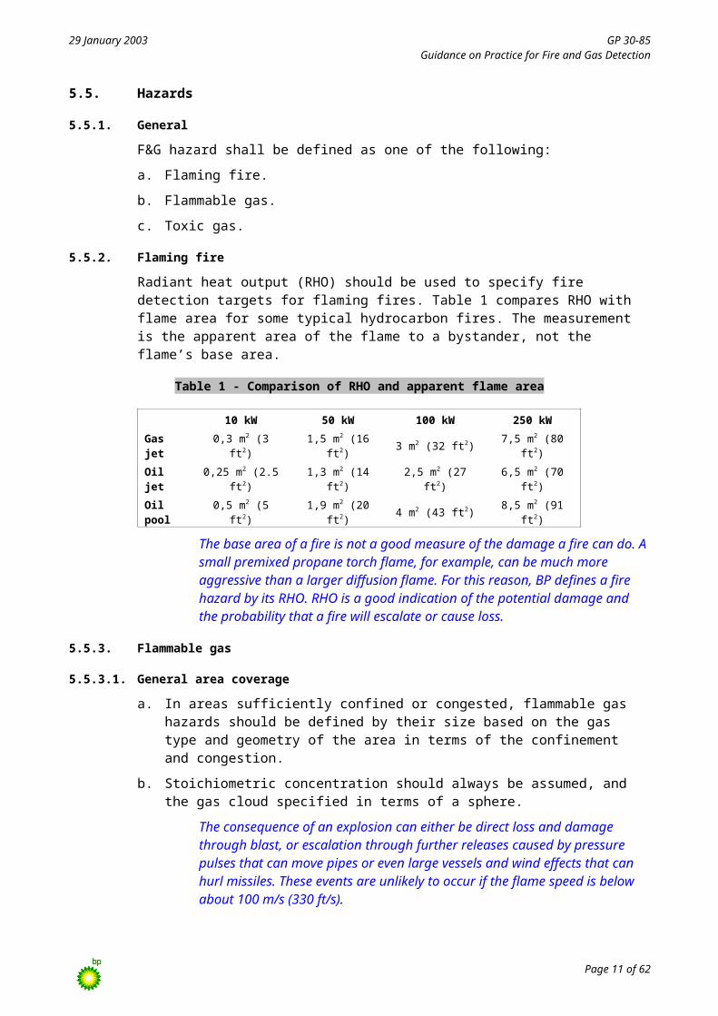
Radiant heat output (RHO) should be used to specify fire detection targets for flaming fires. Table 1 compares RHO with flame area for some typical hydrocarbon fires. The measurement is the apparent area of the flame to a bystander, not the flame’s base area.
Table 1 - Comparison of RHO and apparent flame area
10 kW 50 kW 100 kW 250 kW
Gas jet 0,3 m2 (3 ft2) 1,5 m2 (16 ft2) 3 m2 (32 ft2) 7,5 m2 (80 ft2)
Oil jet 0,25 m2 (2.5 ft2) 1,3 m2 (14 ft2) 2,5 m2 (27 ft2) 6,5 m2 (70 ft2)
Oil pool 0,5 m2 (5 ft2) 1,9 m2 (20 ft2) 4 m2 (43 ft2) 8,5 m2 (91 ft2)
The base area of a fire is not a good measure of the damage a fire can do. A small premixed propane torch flame, for example, can be much more aggressive than a larger diffusion flame. For this reason, BP defines a fire hazard by its RHO. RHO is a good indication of the potential damage and the probability that a fire will escalate or cause loss.
5.5.3. Flammable gas
5.5.3.1. General area coverage
a. In areas sufficiently confined or congested, flammable gas hazards should be defined by their size based on the gas type and geometry of the area in terms of the confinement and congestion.
b. Stoichiometric concentration should always be assumed, and the gas cloud specified in terms of a sphere.
The consequence of an explosion can either be direct loss and damage through blast, or escalation through further releases caused by pressure pulses that can move pipes or even large vessels and wind effects that can hurl missiles. These events are unlikely to occur if the flame speed is below about 100 m/s (330 ft/s).
In the same way that an athlete performing long jumps needs a runup to reach takeoff speed, the flame front of an explosion needs a space in which to accelerate. For many types of gases (typically alkanes) that BP handles at upstream facilities and the geometry of BP plants, the minimum acceleration distance is about 5 m to 6 m (16 ft to 19 ft), even if assuming perfect combustion.
5.5.3.2. Nonhazardous spaces
In areas containing electrical apparatus that have not been assessed as hazardous (as defined by relevant national or international standards) and are supplied by mechanical ventilation for over-pressurisation, the hazard is from gas ingress via the ventilation system.
5.5.3.3. Perimeter monitoring
Gas hazards that may result from ignition of gas that has migrated from large unconfined and uncongested areas containing hydrocarbon handling equipment shall require detection of significant gas volumes leaving the handling area.
Examples of such application would be onshore gas terminals or refineries. The base area of most offshore installations would generally be too small for perimeter detection to be effective.
5.5.4. Toxic gas
Toxic gas hazard performance requirements shall be specified in terms of concentration and response time.
Page 10 of 45
29 January 2003 GP 30-85Guidance on Practice for Fire and Gas Detection
Toxic gas effects are directly linked to concentration, and for some gases, exposure time.
6. Fire detection performance
6.1. General
The method described below is based on many years experience gained at many facilities. The method tailors detection requirements to the type of hazard and levels of risk on a site, and is strongly linked to workforce expectations and major risk reduction requirements. The process is summarised in Figure 1.
a. Fire detection requirements shall be determined using the process defined in Figure 1.
b. Legislative requirements for automatic fire detection shall be established.
c. Site shall be divided into areas for the purpose of determining level of fire detection.
d. Required fire sensitivity levels shall be defined for the site.
e. Areas shall be assigned grades according to defined criteria.
f. Areas shall be assessed to determine where fire detection could reduce risk of personnel exposure to fire.
Area assessment is normally performed through formal safety studies.
g. Potential losses from fire damage shall be assessed in terms of plant replacement or lost production costs. Determination of how automatic fire detection could reduce such losses shall be made.
h. Risks shown in Table 2 should be used to determine the need for and quality of fire detection.
i. Fire detection grading should be performed as follows:
1. A risk classification shall be assigned to each area.
2. A protection grade shall be assigned to each area.
Fire detection requirements for an area are determined by the risk in that area, and defined by the grade of protection required.
6.1.2. Grading basis
Areas within a site shall be assigned a grade based on the following factors:
a. Legislative requirements for automatic fire detection that apply to the site.
b. Safety studies.
c. Required fire sensitivity level.
d. Fire risk category.
e. Type of area, including:
1. Hydrocarbon handling area.
2. Nonhydrocarbon-handling area.
3. Special risk area.
f. Purpose and use of the area, including:
1. Human occupation.
2. Turbines and other engines.
Page 11 of 45

29 January 2003 GP 30-85Guidance on Practice for Fire and Gas Detection
3. Special equipment.
4. Ventilation air intake.
6.1.3. Legislative requirements
Legislative requirements that apply to the site shall be recorded and applied to the grading process.
6.1.4. Safety studies
Previous site safety studies shall be examined and applicable results incorporated into the grading process.
6.2. Fire sensitivity levels fire risk analysis
a. A fire risk analysis for the site should be performed to determine fire sensitivity levels of Low, Medium, and High.
b. Sensitivity levels should be set relative to the type of site.
For example, a fire of sufficient heat output to damage 6 mm (0,25 in) OD instrument tubing may have no effect on 0,9 meter (36 in) heavy wall pipe.
c. Fire risk analysis should be based on one or more of the following:
1. Qualitative analysis based on experience of fire risk analysis.
2. Site-specific safety studies.
3. Project-specific safety studies.
6.3. Fire risk categories
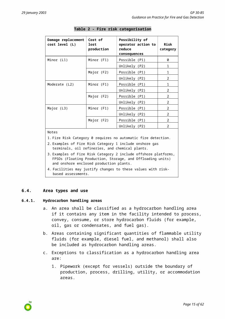
A fire risk category shall be assigned to each area of the site in accordance with Table 2.
Table 2 - Fire risk categorisation
Damage replacement cost level (L)
Cost oflost production
Possibility of operator action to reduce consequences
Risk category
Minor (L1) Minor (F1) Possible (P1) 0
Unlikely (P2) 1
Major (F2) Possible (P1) 1
Unlikely (P2) 2
Moderate (L2) Minor (F1) Possible (P1) 1
Unlikely (P2) 2
Major (F2) Possible (P1) 2
Unlikely (P2) 2
Major (L3) Minor (F1) Possible (P1) 2
Unlikely (P2) 2
Major (F2) Possible (P1) 2
Unlikely (P2) 2
Notes
1. Fire Risk Category 0 requires no automatic fire detection.
2. Examples of Fire Risk Category 1 include onshore gas terminals, oil refineries, and chemical plants.
3. Examples of Fire Risk Category 2 include offshore platforms, FPSOs (Floating Production, Storage, and Offloading units) and onshore enclosed production plants.
4. Facilities may justify changes to these values with risk-based assessments.
Page 12 of 45

29 January 2003 GP 30-85Guidance on Practice for Fire and Gas Detection
6.4. Area types and use
6.4.1. Hydrocarbon handling areas
a. An area shall be classified as a hydrocarbon handling area if it contains any item in the facility intended to process, convey, consume, or store hydrocarbon fluids (for example, oil, gas or condensates, and fuel gas).
b. Areas containing significant quantities of flammable utility fluids (for example, diesel fuel, and methanol) shall also be included as hydrocarbon handling areas.
c. Exceptions to classification as a hydrocarbon handling area are:
1. Pipework (except for vessels) outside the boundary of production, process, drilling, utility, or accommodation areas.
2. Turbine enclosures and other similar machinery enclosures that are described separately.
Note that NFPA 30 (the Flammable and Combustible Liquids Code) uses different and stricter definitions of the words “combustible liquid” and “flammable liquid”.
6.4.2. Nonhydrocarbon handling areas
Nonhydrocarbon handling areas shall be enclosed spaces other than those designated as hydrocarbon handling areas and that have one of the following characteristics:
a. Is normally occupied.
b. Contains machinery or electrical and electronic equipment.
c. Contains significant inventory of flammable materials.
d. Is a designated escape route that could be affected by one of the above (even if it contains no fire hazard of its own).
6.4.3. Special risk areas
6.4.3.1. General
The following area types shall be classified as special risk:
a. Enclosures for turbines, other engines, and similar machinery.
b. Ventilation air intakes.
c. Areas that require fire detection, but to which no other previously defined area type applies.
6.4.3.2. Turbine engine machinery enclosures
Machinery enclosures require early fire detection if either of the following applies:
a. Fires in the enclosure would be difficult or dangerous to control.
b. The type of fire that could occur may quickly lead to unacceptable damage or loss.
Examples of this type of fire are if a fire could be particularly aggressive (high-pressure fuel or lubricating oil fires) or if equipment in the enclosure is easily damaged and critical (fire pumps or analyser houses).
6.4.3.3. Ventilation air intakes
a. Ventilation air intake areas shall include air intakes that supply one of the following:
Page 13 of 45

29 January 2003 GP 30-85Guidance on Practice for Fire and Gas Detection
1. Personnel.
2. Plant areas that require monitoring.
b. Air intakes that require incoming air to be monitored for the protection of the facility or personnel within the area shall have smoke detection fitted.
c. Applications that require toxic gas and fire detection on air intakes shall have fire detection performance requirements specified in terms of:
1. Smoke concentration.
2. Toxic gas concentration.
3. Required response time.
6.4.4. Areas requiring no detection
If fire detection is not required in an area, the reason shall be documented.
Changes in the facility (for example, new storage of flammable materials) may later invalidate that decision.
6.5. Grade definitions
6.5.1. General
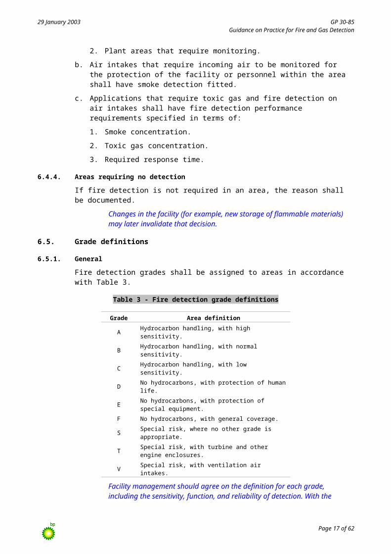
Fire detection grades shall be assigned to areas in accordance with Table 3.
Table 3 - Fire detection grade definitions
Grade Area definition
A Hydrocarbon handling, with high sensitivity.
B Hydrocarbon handling, with normal sensitivity.
C Hydrocarbon handling, with low sensitivity.
D No hydrocarbons, with protection of human life.
E No hydrocarbons, with protection of special equipment.
F No hydrocarbons, with general coverage.
S Special risk, where no other grade is appropriate.
T Special risk, with turbine and other engine enclosures.
V Special risk, with ventilation air intakes.
Facility management should agree on the definition for each grade, including the sensitivity, function, and reliability of detection. With the exception of Grade S, these definitions apply throughout the facility. Because Grade S areas are a special case, each Grade S area has its own definition.
6.5.2. Definition of grades in hydrocarbon handling areas
For each hydrocarbon handling area requiring fire detection, an appropriate grade (A, B, or C) should be set. Specification of each grade should include:
a. Fire detection sensitivity (refer to recommended defaults in Table 4).
b. Response time from the moment the condition occurs until the correct output signal is given.
c. Availability, which is the probability that the fire will be detected and the correct output given. This probability accounts for random equipment failure, design limitations (such as incomplete coverage), and operational failures (such as lockout or maintenance).
d. Requirement for manual or automatic control actions that the system should promote (for example, alarms and plant shutdowns).
Page 14 of 45
29 January 2003 GP 30-85Guidance on Practice for Fire and Gas Detection
Table 4 - Fire detection sensitivity recommended defaults
Sensitivity required - RHO in kW
Fire risk category Area grade For alarm For automatic control action
Category 1Grade A 50 Not required
Grade B 100 Not required
Grade C 500 Not required
Category 2voted
Grade A 10 10
Grade B 10 50
Grade C 100 250
Category 2nonvoted
Grade A 10 10
Grade B 50 50
Grade C 100 100
6.5.3. Definition of grades in nonhydrocarbon handling areas
For each nonhydrocarbon handling area requiring fire detection, an appropriate grade (D, E, F) should be set. The specification should include:
a. Conformance to an industry standard level of performance, if feasible. Table 5 lists typical performance requireents.
b. Availability, which is the probability that the fire will be detected and the correct output given. This accounts for random equipment failure, design limitations such as incomplete coverage, and operational failures such as lockout or maintenance.
c. The need for manual or automatic control actions that the system should promote (for example, alarms and plant shutdowns).
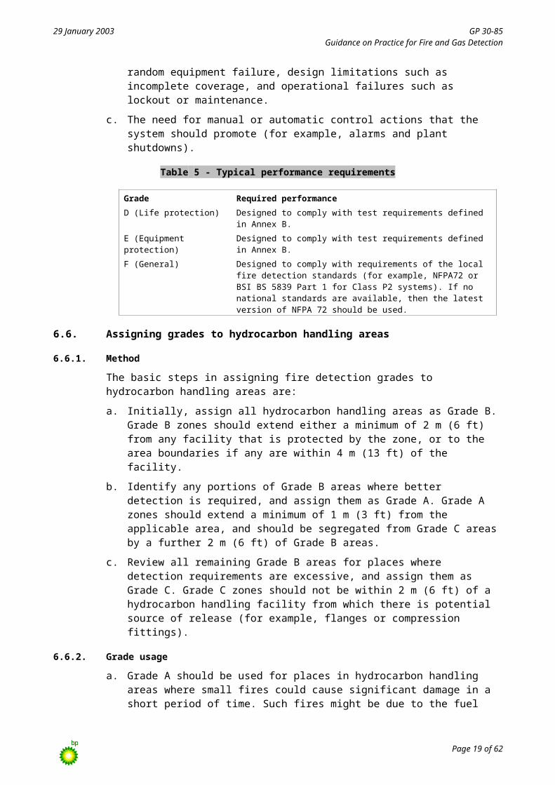
Table 5 - Typical performance requirements
Grade Required performance
D (Life protection) Designed to comply with test requirements defined in Annex B.
E (Equipment protection) Designed to comply with test requirements defined in Annex B.
F (General) Designed to comply with requirements of the local fire detection standards (for example, NFPA72 or BSI BS 5839 Part 1 for Class P2 systems). If no national standards are available, then the latest version of NFPA 72 should be used.
6.6. Assigning grades to hydrocarbon handling areas
6.6.1. Method
The basic steps in assigning fire detection grades to hydrocarbon handling areas are:
a. Initially, assign all hydrocarbon handling areas as Grade B. Grade B zones should extend either a minimum of 2 m (6 ft) from any facility that is protected by the zone, or to the area boundaries if any are within 4 m (13 ft) of the facility.
b. Identify any portions of Grade B areas where better detection is required, and assign them as Grade A. Grade A zones should extend a minimum of 1 m (3 ft) from the applicable area, and should be segregated from Grade C areas by a further 2 m (6 ft) of Grade B areas.
c. Review all remaining Grade B areas for places where detection requirements are excessive, and assign them as Grade C. Grade C zones should not be within 2 m (6 ft) of a hydrocarbon handling facility from which there is potential source of release (for example, flanges or compression fittings).
Page 15 of 45

29 January 2003 GP 30-85Guidance on Practice for Fire and Gas Detection
6.6.2. Grade usage
a. Grade A should be used for places in hydrocarbon handling areas where small fires could cause significant damage in a short period of time. Such fires might be due to the fuel source (for example, high-pressure gas from a compressor) or from the area’s inherent sensitivity to fire (for example, small bore pipework and pump seals). Such risks normally have well-defined risk reduction measures (control actions), some of which may be active and may need to be triggered by automatic fire detection.
b. Grade B is the “normal” level of fire detection in hydrocarbon risk areas. It should be used if another grade is not more appropriate.
c. Grade C should be used if the Grade B level of detection is excessive, and a reduced performance grade is appropriate.
d. The extensions to Grade A and Grade B areas (refer to paragraphs 6.6.a and 6.6.b) may be revised because of site-specific detection targets. The criteria quoted above should be regarded as the minimum.
6.7. Assigning grades to nonhydrocarbon handling areas
a. The basic steps in assigning fire detection grades to nonhydrocarbon risk areas are:
1. Initially, assign Grade F to nonhydrocarbon risk areas.
2. Review Grade F areas for life protection risks and reassign these as Grade D.
3. Review remaining Grade F areas for special equipment protection requirements, and reassign these as Grade E detection.
4. Review remaining Grade F areas for places where detection is not required. Document reasons that fire detection is not required, and note that future changes may invalidate the decision.
b. Grade D should be assigned to rooms that contain a bed (including medical areas) and to escape routes. This performance level protects a sleeping person from a fire in the same cabin or in an adjacent space. If the ventilation system can transfer smoke (either directly or by induction) into escape routes or sleeping areas, these areas should also be Grade D.
c. Grade E should be assigned to rooms that contain electrical or mechanical safety equipment or other high-value equipment (for example, ESD cabinets, emergency power supplies, communication systems, and incident control centres).
d. Grade F should be assigned to all other nonhydrocarbon areas that require fire detection. This should include public areas (common rooms, offices, etc.), utility spaces (voids, etc.), and areas that contain less valuable equipment (storage rooms for flammable materials, etc.).
6.8. Assigning grade to special areas
6.8.1. General
The basic steps in assigning grades to special areas are:
a. Identify turbine and similar machinery enclosures where early detection of an internal fire is required. Assign Grade T and clarify the performance requirements for such areas with the facility management. Table 6 lists typical requirements.
b. Identify air intakes that require fire detection and assign them Grade V. Establish the nature of the hazard and establish agreement with the facility management on the role of detection in achieving the required protection.
c. Inevitably, there are places in the facility where detection requirements do not fall into one of the other eight grades. Identify such areas and assign them Grade S. Special
Page 16 of 45
29 January 2003 GP 30-85Guidance on Practice for Fire and Gas Detection
requirements for each Grade S area should be established in conjunction with facility management.
Table 6 - Typical requirements for Grade T and Grade V
Grade Function Sensitivity
T To detect oil mist or vapour from fuel or lubrication system releases in the enclosure, or smoke arising from combustion of these fuels.
1 dB/m
To detect excessive air temperature in the enclosure and in the ventilation air outlet.An alarm from either form of detection should automatically cause alarm at the control point. Alarms from the temperature detection should cause automatic control actions.
Ambient +40°C (+72°F)
V To detect a smoke plume from an oil or gas fire at the limit of “breatheability” for an exposure time determined by site-specific fire analysis.To prevent smoke at the stated limit from reaching any room of the protected space.
Determined by analysis
6.8.2. Grade T fire detection
Grade T should be assigned to:
a. Turbine enclosures.
b. Other machinery enclosures that require early fire detection. Early fire detection is required if one of the following conditions is present:
1. Fire in the enclosure would be difficult or dangerous to control.
2. Fire could rapidly cause unacceptable damage or loss.
Unacceptable damage or loss can be caused by fires that are particularly aggressive (for example, high pressure fuel or lubricating oil fires).
3. Equipment in the enclosure is easily damaged and is critical.
Examples of such equipment include fire pumps or analyser houses.
6.8.3. Grade V fire detection
a. Grade V should be used in air intakes if the incoming air needs to be monitored for personnel or equipment protection in the area served by the air supply.
b. Types of smoke or toxic gas to monitor shall be specified.
c. Supplied air used to pressurise living space volumes and dilute or prevent leaks of higher smoke concentrations from doors, drains, and other penetrations shall be categorized “breatheable”.
“Breatheable” air is different from “uncontaminated” air. In many cases the supplied air is normally used to pressurise living space volumes and dilute or prevent leaks of higher smoke or toxic gas concentrations from doors, drains and other penetrations. If pressurisation is lost at an early stage of a major incident (for example, in response to very sensitive detection) then the resulting leaks can quickly lead to fatality of the occupants.
d. For areas that require breathable air, the F&G system should detect concentrations of smoke or toxic gas at the upper limit of breatheability.
e. Upper limit of breatheability shall depend on how long personnel are expected to remain in the volume.
f. Specification should refer to the Smoke and Gas Ingress Analysis, if available.
Page 17 of 45

29 January 2003 GP 30-85Guidance on Practice for Fire and Gas Detection
6.8.4. Grade S fire detection
a. Grade S should be assigned if the default grades are not appropriate.
b. Specification of detection for Grade S areas shall be based on:
1. Type of fire and its fuel (the hazard).
2. Risk to be mitigated.
3. Planned actions, including response time (the role).
4. Required sensitivity (in RHO).
5. Required system outputs (the function).
6. Worst acceptable failure on demand rate for detection elements (the availability).
6.8.5. Control actions from fire detection
a. Automatic control actions from fire detection should be targeted for the hazard they are protecting against on an area-by-area basis.
b. Manual response to fire alarms that can be demonstrated to be sufficiently effective are preferred to automatic systems.
It is important that automatic control actions from fire detection are targeted, rather than taking a blanket approach for the facility. For example, in a facility that contains both office and process facilities, it makes no sense to shut down the process on detection of an office fire. In fact, this increases the probability of hazard in the process facility.
Higher performance detection can provide earlier warnings, allowing manual action to be taken in preference to automatic control action.
6.9. Fire detection voting
6.9.1. General
Voting logic should be used for automatic control actions where the anticipated loss from unwanted response (false control action) from the detection equipment is unacceptable.
6.9.2. Grade A, Grade B, and Grade C
a. For Grade A, Grade B, and Grade C areas where automatic control actions cause process or plant shutdown or activation of fire protection systems, 2ooN voting logic (two of the detectors or circuits in the voting group in alarm) should be employed for all electrical and electronic detection systems.
b. Pneumatic fire detection systems may be used in Grade A, Grade B, and Grade C areas without voting if care is taken in their design and installation to minimise unwanted actions that result in production losses.
There are at present no optical flame detection systems that have sufficient history to justify their being used in a nonvoting mode for automatic control actions in the majority of BP applications. When deciding on the requirement for voting detectors, consideration should be given to the cost of adding the necessary number of detectors to achieve the performance targets versus the cost of unwanted production shutdowns.
6.9.3. Grades D, Grade E, and Grade F
For Grade D, Grade E, and Grade F areas, unwanted automatic control actions are unlikely to cause significant losses, so detectors should not normally be voted.
Page 18 of 45
29 January 2003 GP 30-85Guidance on Practice for Fire and Gas Detection
6.9.4. Grade S
For Grade S areas, detector voting requirements should be assessed on a case-by-case basis.
6.9.5. Grade T
For Grade T areas, detectors used to automatically shut down the machine and initiate the fire protection system should be voted in a 2ooN configuration.
6.9.6. Grade V
For Grade V areas, unwanted automatic control actions are unlikely to cause significant losses, so detectors should not normally be voted.
6.10. Manual fire alarm stations
Manual fire alarm stations (also called manual alarm callpoints) are for personnel to raise alarms.
a. Manual fire alarm station devices should be located at exits on designated escape routes.
b. Maximum personnel travel distance on designated escape routes between the exited area to the nearest station shall be determined by national standards, but shall not exceed 60 m (200 ft). If the travel distance between exits exceeds the maximum limit, additional manual fire alarm stations shall be positioned throughout the designated escape routes.
c. The role of manual fire alarms should be clearly defined and personnel properly trained in their use.
d. The use of alarms on some facilities for events other than fire (for example, man overboard) should be considered.
e. If manual fire stations are to be used to raise alarms for events other than fire, additional stations shall be required to allow for these extra functions.
7. Flammable gas detection performance
7.1. General
The method described below is based on many years experience gained at many facilities. The method tailors detection requirements to the type of hazard and levels of risk on a site, and is strongly linked to workforce expectations and major risk reduction requirements. The process is summarised in Figure 2.
a. Flammable gas detection requirements shall be determined using the process defined in Figure 2.
b. Initially, any legislative requirements for automatic gas detection should be determined.
c. Next, each area should be assessed for risks from gas explosion.
d. Gas detection should be required for an area if any of the following apply:
1. Areas that are classified as hazardous in accordance with either GP 12-60 or with the recognised national standard shall require gas detection. Exceptions are areas that are too small to contain a gas cloud large enough to be an explosion hazard.
2. Areas that are nonhazardous into which gas could feasibly be transported, either by mechanical ventilation systems, differential pressures, or air movement) require gas detection. The penetrations through which gas can be transported include air supply ducts and single-door accessways coming from classified hazardous areas. Exceptions are self-closing extract ducts, airlocked entrances, or single emergency doors that are not often used.
Page 19 of 45

29 January 2003 GP 30-85Guidance on Practice for Fire and Gas Detection
3. Areas in which large volumes of gas could be released and transported to other areas where an explosion hazard could be formed.
A nontoxic flammable gas release is not normally hazardous unless ignited. If the gas is ignited the result can be a flash fire, a sustained fire, or an explosion. If fire detection is provided in accordance with this GP, it is assumed that all risks associated with sustained fires are addressed.
Current technology does not allow gas detection to reliably detect all leaks. The best that can be reliably achieved is the detection of a gas cloud with size and concentration to make it a sufficient threat to require action. Obviously, some leaks will be detected. Gas detection would not usually be fitted in areas where gas at hazardous concentrations is normally present.
7.2. Risk volume assessment
7.2.1. General
a. Flammable gas detection shall be provided in areas (risk volumes) where ignited gas clouds could cause damage from explosion overpressure.
b. In these areas, the smallest gas cloud that has the potential to cause such damage shall be specified as the detection target.
7.2.2. Small enclosed volumes
a. Small volumes shall be defined as less than 1 000 m3 (35 000 ft3).
These areas can be either naturally ventilated or force ventilated.
b. Small volumes that are naturally ventilated shall require detection of a spherical gas cloud 4 m (13 ft) in diameter anywhere in the volume.
c. Small volumes that are mechanically ventilated may have gas detection at the ventilation air outlet instead of inside the volume if the volume has the following characteristics:
1. Contains a source of release.
2. Has normal air change rate greater than 60 air changes per hour.
d. In very small enclosures, defined as less than 100 m3 (3 500 ft3), the minimum number of detectors may be set by either of the following:
1. Special automatic action requirements.
2. Voting philosophy for the facility.
7.2.3. Large fully enclosed volumes
a. Large fully enclosed volumes shall be defined as greater than 1 000 m3 (35 000 ft3).
b. Large fully enclosed volumes may have explosion protection in the form of inerting systems.
c. If explosion protection is installed, detection shall be required of a spherical gas cloud 5 m (16 ft) in diameter anywhere in the volume.
d. If explosion protection is not installed, detection shall be required of a spherical gas cloud 4 m (13 ft) in diameter anywhere in the volume.
7.2.4. Large partially enclosed volumes
a. Large partially enclosed volumes shall be defined as:
1. Greater than 1 000 m3 (35 000 ft3).
Page 20 of 45

29 January 2003 GP 30-85Guidance on Practice for Fire and Gas Detection
2. Having a blockage ratio greater than 0,3.
b. Large partially enclosed volumes shall have detection of a spherical gas cloud 5 m (16 ft) in diameter anywhere in the volume.
7.2.5. Open volumes
a. For large open volumes with congested parts having a blockage ratio less than 0,3, detection of a spherical gas cloud 10 m (33 ft) in diameter anywhere in the volume shall be required.
b. For large open areas that contain pockets with a blockage ratio greater than 0,3, detection of a spherical gas cloud of 5 m (16 ft) in diameter anywhere within the pocket shall be required.
c. Perimeter detection may be used in place of volumetric detection for large open volumes if the following conditions are present:
1. The volume has no congested parts with a blockage ratio greater than 0,3.
2. The hazard of concern is migration of gas to other areas.
Perimeter detection would normally be used in onshore facilities such as gas terminals or oil refineries. Perimeter detection would not normally be used in offshore installations because migration of gas from the installation is not usually a hazard.
d. If the flammable gas is also toxic, more local detection may be required at onshore facilities.
7.2.6. Liquid phase releases
a. Low-level detectors (for heavy gas hazards) should be installed in areas that contain inventories of process fluids, which if released to atmosphere, would remain in liquid state for a significant period.
b. Low-level detectors shall be installed at no more than 0,5 m (1,6 ft) above local deck or grade.
c. Low-level detectors should be arranged on a 5 m (16 ft) triangular grid around potential heavy gas release points.
A liquefied gas release can behave very differently from a vapour phase release. First, less mixing occurs with the air. Second, the heat required to evaporate the gas is often more than available from the surroundings, so released fluids remain liquid for some time. The local gas cloud is therefore relatively dense and cold. This gas or vapour tends to slump, especially in low air movement areas. Throughout the length of the plume, gas at the outer edges is entrained into and carried away by local air movement. At some point downwind, the whole plume may have warmed sufficiently to "lift off" and be entrained in the ambient flow field.
7.2.7. Leak detection
a. Detection systems designed for detection of gas clouds large enough to potentially cause damage from explosion overpressure shall not be relied upon for leak detection.
The gas detection requirements previously discussed in this section relate to detection of gas clouds of a size that have the potential to cause damage from explosion overpressure.
b. A leak detection system may be installed in addition to, and not to replace in whole or in part, a volumetric gas detection system where the fluid that could be released is in the gaseous phase, and is at pressure of 10 barg (150 psig) or greater.
Page 21 of 45

29 January 2003 GP 30-85Guidance on Practice for Fire and Gas Detection
7.2.8. Air intakes
a. Enclosed volumes with no source of release, but which contain sources of ignition (for example, accommodation blocks or electrical equipment rooms) shall require fast-response gas detection at the air inlets to ensure that gas is prevented from entering an area containing an ignition source. The passage of gas in the ducts should be stopped before it crosses the boundary of the protected space.
b. Total response time of detectors, control systems, and dampers should be:
1. Shorter than the time needed for gas to reach the area boundary after passing the gas detector.
2. Verified by site measurement.
7.3. Gas detection control actions
a. Automatic control actions from gas detection should be targeted for the hazard they are protecting against in each area.
b. Manual response to gas alarms that can be demonstrated to be sufficiently effective is preferred to automatic systems.
It is important to target automatic control actions from gas detection, rather than to use a blanket approach for the facility. For example, detection of gas at a ventilation air intake to a building cannot be used to infer the formation of an explosion hazard in adjacent process areas.
7.4. Gas detection voting
a. If anticipated loss from unwanted response by detection equipment (false control action) is unacceptable, voting logic should be used for automatic control actions.
b. If detectors on BP facilities have had satisfactory reliability for a number of years, then they need not be voted.
c. Infrared gas detectors may be used in 1ooN, 1oo2d, or 2ooN voting configurations.
d. Detectors in 1ooN mode should:
1. Alarm if any single device reaches 20% of scale.
2. Prompt automatic control actions at 60% of scale.
e. Detectors in 1oo2d mode should:
1. Alarm if any single device reaches 20% of scale.
2. Prompt automatic control actions if two devices reach 20% of scale.
f. If any detectors in the 1oo2d voting group are in fault (including beam block), this detector shall count as one device at 20% of scale in terms of voting logic.
g. Detectors in 2ooN mode should:
1. Alarm if any single device reaches 20% of scale.
2. Prompt automatic control actions if two devices reach 20% of scale.
h. Detector faults shall not be included in voting logic for automatic control actions in 2ooN configurations.
i. Whether to use 1oo2d or 2ooN voting logic should be determined by the availability requirements of the system.
For open path gas detectors, little benefit is gained in having two levels of alarm, because their range is usually limited to a small band of 0 LELmetres to
Page 22 of 45

29 January 2003 GP 30-85Guidance on Practice for Fire and Gas Detection
5 LELmetres, and gas can be present up to 100% by volume. The difference between 20% and 60% of scale is roughly the difference of 2% by volume for the gases commonly encountered at BP facilities. Two levels of alarm should be retained on 1ooN systems as a preliminary alarm that may be used to announce the onset of detector failure.
8. Toxic gas detection performance
8.1. General
a. Safe working practices constitute the primary protection of personnel from toxic gases.
b. The threat to personnel from toxic gas shall be clearly identified and recorded along with the working practices for keeping personnel safe.
c. If toxic gas detectors are installed, their role and performance shall also be documented to ensure that personnel do not rely on these devices for overall safety.
This is because some toxic gas detection devices are suitable for detecting leaks in lethal service chemicals, but are not sensitive enough to detect the lower exposure limit concentrations for personnel protection.
d. Table 7 summaries exposure limits for the more common toxic gases encountered at BP facilities in the UK and USA. The table should be a guide for other locations unless stricter national requirements apply.
Table 7 - Exposure limits for common toxic gases
COSHH (UK) OSHA (USA)
Toxic gas STEL (ppm) TWA (ppm) STEL (ppm) TWA (ppm)
CO 200 30 400 35
CO2 15 000 5 000 30 000 10 000
H2S 15 10 15 10
HCN 4.7 N/A
HF 3 N/A 6 3
Note:STEL – Short-term exposure level.TWA – Time-weighted average.
8.2. Carbon monoxide
a. Fixed carbon monoxide (CO) detectors may be installed in enclosed spaces where personnel are present and there is a threat to them from machinery exhaust fumes inadvertently being leaked into the area.
b. Detectors should be placed where personnel are present during normal operations (designated entrances, exits, and walkways).
c. Detectors should alarm at the TWA (time-weighted average) threshold defined by local legislation or guidance.
d. The rationale for detector placement shall be clearly documented to allow system audits.
e. Use of carbon monoxide detectors shall not detract from the need for formal working practices to protect personnel from CO hazard.
8.3. Carbon dioxide
a. If the threat to personnel is from machinery exhaust fumes, CO detectors should be used rather than CO2 detectors, because CO is the primary toxin.
Page 23 of 45

29 January 2003 GP 30-85Guidance on Practice for Fire and Gas Detection
b. If CO2 may be a threat to personnel without CO being present, CO2 detectors may be used.
c. Detectors should be placed where personnel are present during normal operations (designated entrances, exits, and walkways).
d. Detectors should alarm at the TWA threshold defined by local legislation or guidance.
e. The rationale for detector placement shall be clearly documented to allow system audits.
f. Use of these detectors shall not detract from the need for formal working practices to protect personnel from CO and CO2 hazard.
8.4. Hydrogen sulphide
a. If flammable gas detection using infrared technology is installed, it may be used to infer H2S concentration if the hydrocarbon gas content in any release is at least 1 000 times the H2S content.
b. Detectors should be placed where personnel may be present during normal operations (designated entrances, exits, and walkways).
c. Detectors should alarm at the TWA threshold defined by local legislation or guidance.
d. The rationale for detector placement shall be clearly documented to allow system audits.
e. Use of detectors shall not detract from the need for formal working practices to protect personnel from H2S hazard.
8.5. Hydrogen cyanide
a. Fixed hydrogen cyanide (HCN) detectors should be installed in enclosed spaces where there is a threat to personnel and personnel are present.
b. Detectors should also be placed where personnel may be present during normal operations (designated entrances, exits, and walkways).
c. Detectors should alarm at the TWA threshold defined by local legislation or guidance.
d. The rationale for detector placement shall be clearly documented to allow system audits.
e. Use of these detectors shall not detract from the need for formal working practices to protect personnel from HCN gas hazard.
8.6. Hydrogen fluoride
a. Fixed hydrogen fluoride (HF) detectors should be installed in enclosed spaces where there is a threat to personnel and personnel are normally present.
b. Detectors should also be placed where personnel may be present during normal operations (designated entrances, exits, and walkways).
c. Detectors should alarm at the TWA threshold defined by local legislation or guidance.
d. The rationale for detector placement shall be clearly documented to allow system audits.
e. Use of these detectors shall not detract from the need for formal working practices to protect personnel from HF gas hazard.
9. Safe havens
a. Safe havens (also called temporary refuges) shall be defined as areas where personnel muster in an emergency.
Safe havens have special detection requirements.
Page 24 of 45

29 January 2003 GP 30-85Guidance on Practice for Fire and Gas Detection
b. The time that personnel are required to stay in these areas shall be based on the type of emergency.
c. In terms of F&G detection, performance targets shall be specific to the conditions of the facility and shall consider the time that personnel are expected to remain within the safe haven.
d. Performance targets should be set in accordance with the BP smoke and gas ingress analysis procedure, if available.
10. Detector type selection
10.1. General
a. Detectors shall be selected to detect the appropriate hazard.
b. Detectors shall be capable of detecting hazards as they occur on the site especially considering onsite sources that will affect device detection performance.
Detector performance can be adversely affected by common contaminants on a site or by radiation sources, such as a hot process plant.
c. Consideration shall be given to sources on the site that could cause the detector to false alarm.
d. Detector types and use shall comply with GIS 30-851.
10.2. Flame
10.2.1. General
a. The preferred method of fire detection shall be optical flame detection in the majority of hydrocarbon fire risk applications (Grade A, Grade B, and Grade C).
b. Equipment should detect fires specific for the fuel types that are located in the areas detection is covering.
c. Facility-specific contaminants and interfering sources that can affect the detector’s ability to see the fire or affect detector false alarm immunity shall be considered.
d. Selection process should be formally documented to allow future audits.
10.2.2. Closed circuit television
a. Closed circuit television (CCTV) flame detectors may be used at facilities that process hydrocarbon gas or liquids.
b. In applications where other optical flame detection systems do not perform satisfactorily due to excessive false alarms from reflections of process flares (for example, top deck process areas on offshore platforms), CCTV systems may be used.
CCTV systems, developed for these situations, continually and automatically process video signals, testing for a suspected fire. On detection, the system automatically alarms and displays a video image of the area in the control room.
c. CCTV devices may be used for detection of gas and liquid hydrocarbon fires.
d. CCTV devices should not be used for invisible fires from methanol or hydrogen.
10.2.3. Infrared
a. Infrared (IR) flame detectors may be used on facilities that process hydrocarbon gas or liquids.
Page 25 of 45

29 January 2003 GP 30-85Guidance on Practice for Fire and Gas Detection
b. Preferred infrared devices shall be single frequency with advanced signal processing operating in the middle IR region of the spectrum (4,3 microns), rather than multiwavelength devices.
c. IR detectors should not be used in areas where flare radiation can be seen, either directly or reflected.
Infrared flame detectors are suitable for all gas and liquid hydrocarbon fires. Fires of other fuels (such as hydrogen) may be impossible for the sensors to see. Other fuels, such as methanol, may be seen but very poorly. All IR flame detectors are affected to some extent by background “blackbody” radiation sources in their field of view (hot plant site, people, the sun, etc.). Some detectors suffer reduced sensitivity while others give false alarms, especially if the source appears to flicker.
10.2.4. Ultraviolet
a. Ultraviolet (UV) flame detectors may be used at facilities where the only fuel sources are hydrogen or hydrocarbon gas.
b. UV detectors are unsuitable for detection of hydrocarbon liquid fires and shall not be used for such applications.
c. UV detectors shall not be used in areas where flare radiation can be seen, either directly or reflected.
UV detectors can see clean burning gas fires, including hydrogen fires. If clean burning fire is the only hazard in the area, UV detectors may be used, but they are best located well below roof level in case smoke is given off from other materials (for example, paint or cables). Using UV detectors with hydrocarbon liquid fires presents two problems: the fires can emit very little UV, and smoke absorbs UV.
10.2.5. Combined ultraviolet and infrared
Combined UV/IR detectors are not recommended for general use.
Combined UV/IR devices operate in two modes: “UV and IR”, or “UV or IR”. The “UV and IR” mode requires detection of both wavebands before a shutdown signal is given. Some devices give a preliminary alarm on detection of only one waveband. The purpose is to reject unwanted alarms, because few sources emit as strongly as clean fires in both spectral regions. Such devices may be beneficial if fires can only be clean burning, if they emit IR and UV, and if the windows of the detectors can be kept scrupulously clean.
10.3. Gas
10.3.1. General
a. Unless infrared is not suitable for the gas types to be detected, the infrared detectors shall be preferred for detecting gas.
b. Infrared gas detectors should not be used to detect gases that have no infrared absorption characteristics (for example, hydrogen).
Infrared gas detectors are suitable for detection of a large range of gases, including alkanes that are commonly found in BP facilities. However, gases that have no infrared absorption characteristics (for example, hydrogen) are also found in BP facilities.
Be aware that any plastic obstructions in the beam path are seen by infrared detectors as hydrocarbons.
Page 26 of 45
29 January 2003 GP 30-85Guidance on Practice for Fire and Gas Detection
c. The preferred gas detection method for applications where clear paths exist shall be open path gas detectors, rather than point gas detectors.
d. Open path gas detectors based on infrared absorption should be used for:
1. Detection of gas clouds with explosion potential.
2. Perimeter monitoring of large onshore facilities.
10.3.2. Catalytic bead
a. Catalytic bead gas detectors should not be used for general use. They should be used only in applications where other technologies do not detect the target gases.
Catalytic bead gas detectors have poor availability and response time. These devices have many undetected failure modes, such as catalyst poisoning and blockage of the sintered flame arrester.
b. Catalytic bead gas devices are suitable for use in clean areas where hydrogen detection is required.
10.3.3. Electrochemical cell
a. Electrochemical cell devices may be used for the detection of toxic gases.
b. Due to the poor availability and undetected failures, electrochemical cell devices shall not be relied upon for personnel safety.
At this time, there are no practical optical toxic gas detectors available for use in the intended range of applications.
10.3.4. Point infrared
Point infrared gas detectors may be used:
1. Space or congestion prohibits the use of open path gas detectors.
2. Detection of spot flammability at a particular location is required.
10.3.5. Open path
a. Open path detection systems using separate transmitters and receivers shall be preferred to combined transmitters/receivers using reflector panels.
b. Open path devices with diagnostics that prevent poorly installed and commissioned systems from going online should be used.
The main role of such instruments is to monitor the level of gas hazard in an area. Their integrating method of measurement makes them more suited to indicate the presence of explosion hazards than point devices that only measure local flammability.
10.3.6. Sensitivity
Gas detector specification should ensure that gas detection is such that a hazard is never underestimated. This objective requires a detailed knowledge of:
a. Gas mixtures that may be released.
b. Limits of flammability of the gases.
c. Response characteristics of the selected detector technology.
10.3.7. Ultrasonic
a. Ultrasonic gas leak detection shall be used only in addition to a volumetric gas detection system.
Page 27 of 45
29 January 2003 GP 30-85Guidance on Practice for Fire and Gas Detection
b. Ultrasonic gas leak detection shall not replace a volumetric gas detection system in whole or in part.
c. Use of time delays should be minimised and should never exceed 30 seconds.
d. Background ultrasonic levels within the detection area should be mapped to determine:
1. Alarm threshold.
2. Number and spacing of detectors.
10.4. Heat
10.4.1. General
Heat detection may be used if one of the following conditions is present:
1. Other forms of detection are not suited to detection of the hazards.
2. Other forms of detection would have unacceptable false alarm rates.
Heat detectors are less sensitive than other fire detection technologies, and on this basis their use is generally discouraged. There are some applications (for example, turbine enclosures) that have a relatively small volume to be protected, where heat detectors are acceptable.
10.4.2. Pneumatic
a. Pneumatic tube, frangible bulb, and fusible plug systems may be used for either of the following applications:
1. If direct control of firewater deluge valves is required to cover specific areas of the facility.
2. General area coverage.
b. If used as a backup to flame detectors, the sensitivity of the system may be an order of magnitude less than the automatic control action threshold set for the flame detection system.
Pneumatic systems are pressurised so that if the fire detecting element is ruptured, the pressure quickly falls, causing the deluge valve to open and the transmitter to alarm and possibly take control action. Instrument air is supplied through a filter regulator and a small, variable restriction orifice. Flow of makeup air into the tube is just sufficient to maintain a pressure transmitter above its alarm setting and to compensate for minor leakage from fittings. Tube and bulb systems suffer false alarms from mechanical damage.
10.4.3. Electrical linear
Electrical linear heat detection may be used for either of the following applications:
a. If coverage of specific areas of the facility is required.
b. General area coverage.
Electrical linear heat detectors have two types: those that respond to an average temperature along their length, and those that respond to the highest temperature at a point along their length. Both types have a factory preset response threshold and produce an alarm-only output. These systems have not generally been used at BP hydrocarbon handling facilities.
10.4.4. Optical linear
Optical linear heat detection may be used for either of the following applications:
Page 28 of 45

29 January 2003 GP 30-85Guidance on Practice for Fire and Gas Detection
a. If coverage of specific areas of the facility is required.
b. General area coverage.
Optical linear heat detection uses a property (Ramman scattering) of a type of optical fibre that changes with temperature. A sophisticated control system can monitor the temperature at any point along the fibre. Available versions shield the fibre for most of its length, removing the shielding at specific points where a heat collector is coupled to the fibre. This effectively turns the system into a string of point heat detectors. These systems offer the advantage of continuous analogue readings from a large number of points, but have little practical value in most BP applications where the requirement is usually to detect the presence of fire, rather than absolute temperature measurement.
10.4.5. Point devices
a. Point heat detection should only be used in special applications where flame or smoke detection is not appropriate.
b. Bimetallic strips may be used in situations such as turbine enclosures or ventilation ducts for turbines.n bnb
c. Electronic types (thermistors) may be used where aesthetics is a primary consideration (for example, in accommodation areas).
Several types of point heat detector are available, based on technologies like bimetallic strips, IR sensors, and thermistors. Bimetallic devices can respond at a factory set temperature and can incorporate an additional trip on a high rate of rise in temperature, again preset by the manufacturer. The electronic types (thermistors, etc.) are generally less reliable, more expensive, and more complex. They are generally used only if aesthetics is a primary consideration.
10.5. Oil mist
a. Oil mist detectors should be used in areas where the fire may be preceded by a release of high-pressure flammable liquid, such as diesel or lubrication oil.
b. Oil mist detectors should be used in machinery spaces or turbine exhaust ducts.
Oil mist detectors are essentially optical obscuration instruments operating on principles similar to open path smoke detectors. They are particularly useful in engine enclosures for indicating the release of high-pressure fuel or lubrication oil, which can lead to particularly aggressive and damaging fires. If the oil mist ignites, the instrument doubles as an optical smoke detector.
10.6. Smoke
10.6.1. General
The following shall be considered in the selection of smoke detection equipment:
a. Smoke detection technologies fall into two categories:
1. The more frequently used devices designed to comply with the sensitivity levels set out in national and international standards.
2. Other devices designed to operate outside this sensitivity band.
A number of smoke detection technologies are available.
b. High-sensitivity smoke detectors are of two basic types:
1. Aspirated optical systems.
2. Addressable point optical systems.
Page 29 of 45

29 January 2003 GP 30-85Guidance on Practice for Fire and Gas Detection
c. Less sensitive smoke detection systems are available for special applications. These smoke detection systems are tuned to the level of smoke that affects human life.
10.6.2. Aspirating systems
a. High-sensitivity aspirating smoke detectors should be used in Grade E areas.
One type of high-sensitivity aspirating smoke detector is known as “VESDA”. VESDA stands for Very Early Smoke Detection Apparatus, and is a registered trademark of Vision Systems. Mention of the VESDA name in this GP should not be inferred as a preference for this product over other similar aspirating type systems (for example, Kidde Analazer).
b. High-sensitivity aspirating type smoke detector systems should be designed to function both with and without the HVAC system running.
High-sensitivity aspirating type smoke detectors are normally used to monitor extracted air from rooms containing high-criticality electrical or electronic equipment. Their sensitivity is adjustable, and at maximum is far higher than BP requires.
c. The efficiency of the system is dependent on the design of the sampling system and should be checked on commissioning, using a standard test. Thereafter, testing, calibration, and maintenance shall be performed onsite.
d. Point-type devices should not be used in Grade E areas.
Point-type devices are discouraged because they are generally more difficult to engineer and can be significantly affected by local environment variations. Their overall cost of installation and ownership is generally higher.
10.6.3. Closed circuit television
Closed circuit television (CCTV) may be considered in areas that are normally unattended and where manual response would take too long to prevent losses or allow facility restart.
CCTV smoke detectors require good lighting to see smoke. These devices are not as sensitive as aspirating systems, because they operate by detecting visible smoke.
10.6.4. Ionisation
a. Ionisation smoke detectors may be used in Grade F or Grade V areas, if the concern is property protection.
b. Ionisation smoke detectors shall not be used in sleeping areas.
Ionisation smoke detectors are not suited to sleeping areas, because they may not detect a fire in time to save the lives of personnel in the room. They may be used to detect fire in some equipment spaces (depending on the ventilation), but not for highly critical electrical or electronic equipment. These detectors are sensitive to gas and liquid hydrocarbon fires, but not robust enough to be used in plant areas. They are suited to monitoring air intake ducts if their slow response time is acceptable. They may be too sensitive for some applications.
10.6.5. Point optical
a. High-sensitivity point type smoke detectors should be used in Grade D areas for the protection of sleeping personnel.
b. High-sensitivity point type smoke detectors may be combined with other detection techniques for the protection of sleeping personnel.
c. Standard sensitivity point type optical smoke detectors may be used in Grade F areas.
Page 30 of 45
29 January 2003 GP 30-85Guidance on Practice for Fire and Gas Detection
Optical smoke detectors are a less sensitive option than ionisation types for smoke generated by electrical fires. Detectors are available in combinations of detection technology. Generally, these devices have similar sensitivity to ionisation types for detection of most fires, while retaining improved performance for detection of electrical fires.
10.6.6. Open path
Open path smoke detectors should be used in one of the following:
a. Large open areas (Grade F) where point detectors would be difficult or expensive to deploy,
b. Grade V applications for personnel protection.
These are essentially obscuration monitors. Anything that reduces the intensity of light (near IR) in the path of the beam alarms at a given level. A particularly rugged version of the obscuration detector, developed from an exhaust stack analyser, is used in ventilation ducts to detect when the level of smoke in the air reaches the limit of breatheability for one hour. This is particularly valuable in safe haven (temporary refuge) applications where the survival of personnel depends on maintaining pressurisation of the refuge.
11. Detector deployment
11.1. General
The following shall be considered in deploying detectors:
a. Correct installation and orientation of detection equipment is critical to reliable performance.
b. Mounting arrangements should ensure correct operation even in the presence of vibration of the supporting steelwork.
c. Maintenance access should be considered. Flame detectors should be placed between 3 m (10 ft) and 4 m (13 ft) above local deck or access platform.
The 3 m (10 ft) and 4 m (13 ft) distance above local deck or access platform was determined from reviewing the practice across a number of BP facilities. In these facilities, it has been allowable for personnel to access equipment at these elevations from portable ladders, rather having to use temporary structures such as scaffolding. In practice, placing the detectors lower than 3 m (10 ft) above local deck or access platform means that they have more restricted views and therefore more detectors are required to achieve the same level of coverage.
11.2. Flame
a. Flame detector deployment should be optimised using computer-aided coverage assessment tools.
b. If computer-aided coverage assessment tools are not used, drawings should be required to show the intended coverage of each detector, including overlapping voting coverage.
c. The maximum distance from detector to the item or area requiring coverage shall be set after considering the fire size and fuel type, and any desensitising effects from local conditions.
11.3. Gas
a. Gas detector deployment should be optimised using computer-aided coverage assessment tools.
Page 31 of 45

29 January 2003 GP 30-85Guidance on Practice for Fire and Gas Detection
b. If computer-aided coverage assessment tools are not used, drawings should be used that show the intended coverage of each detector, including overlapping voting coverage.
c. If areas are assessed as having explosion potential, detectors should be installed to ensure that a cloud of given size and concentration cannot exist without encompassing at least one detector or detection path.
d. Maintenance access should be considered. Gas detectors should be placed between 3 m (10 ft) and 4 m (13 ft) above local deck or access platform.
e. Open path gas detectors should be installed in locations where their paths will not be interrupted by routine operations.
In practice, placing open path detectors lower than 3 m (10 ft) above local deck or access platform will result in frequent blockage of the paths by personnel carrying out routine operations. These interruptions cause unnecessary nuisance fault indications at the control point.
f. Low-level gas detectors aimed at detecting heavy gas hazards should be located no higher than 300 mm (1 ft) above local deck or grade.
g. Elevation of toxic gas detectors shall be specified based on their intended role and the nature of gases in the intended installation.
11.4. Heat
a. Heat detectors in Grade F areas should be installed in accordance with national guidance. If no national guidance is available, NFPA 72 should be used to determine detector deployment.
b. If pneumatic tubing is used in Grade A or Grade B applications, detection tubing should be installed local to the protected facility areas, and at the required spacing for detection of the target fire sizes.
For example, to detect a fire of 50 kW RHO, the tubing would need to be installed so that all areas of the protected site are within 2 m (6 ft) of a detection tube.
c. Pneumatic detection tube shall be protected from accidental damage (for example, with an inverted cable tray).
11.5. Oil mist
a. Oil mist detectors may be installed in Grade F, Grade T, or Grade V areas.
b. In Grade F areas, they should be installed in accordance with national guidance. If no national guidance is available, NFPA 72 should be used to determine detector deployment.
c. In Grade T areas, oil mist detectors should be installed throughout the room on a 5 m (16 ft) pitch along the longitudinal axis of the room, covering the main air exhaust streams, or in areas with air change rates greater than 60 per hour, in the HVAC exhaust ducting.
d. In Grade V areas, oil mist detectors should be installed in the air exhaust ducting.
11.6. Smoke
a. Smoke detectors in Grade F areas should be installed in accordance with national guidance. If no national guidance is available, NFPA 72 should be used to determine detector deployment.
b. Smoke detectors in Grade D or Grade E areas require special design to determine the number and location of detectors, and detector sampling points.
The Vendor proprietary computer model should be used to establish base design.
Page 32 of 45

29 January 2003 GP 30-85Guidance on Practice for Fire and Gas Detection
c. In all smoke detector applications in Grade D or Grade E areas, the installed system shall be tested using the tests specified in the grading.
12. Control and indicating equipment
a. Detectors should be connected to suitable control and indicating equipment.
b. Type and configuration of control and indicating equipment should be determined by formal analysis.
c. Control and indicating equipment shall comply with GIS 30-851.
d. The safety integrity level (SIL) of the F&G detection functions shall be set in accordance with GP 30-76.
e. The SIL should be used to determine an appropriate F&G system configuration, including interface to the shutdown system, in accordance with GP 30-80.
GP 30-80 covers requirements for choice of equipment, minimum architectures, reliability, robustness, power supply, integration, installation, commissioning, documentation and verification.
f. The preferred detection systems for non-SIL-rated and SIL 1 applications shall be addressable.
g. Addressable detection systems should not be used at SIL 2 and above unless justified by complying with the requirements of IEC 61508 in full as described in GP 30-80.
h. Operator interfaces shall comply with GP 30-45.
13. Maintenance
a. A maintenance strategy for the F&G system should be established in accordance with GP 30-81 before commissioning the system. The strategy should define necessary maintenance and testing based on:
1. Location of the equipment and its environment.
2. Failure modes.
3. Performance targets.
b. The strategy should include maintenance/testing frequencies for detection devices based on Vendor recommendations or BP experience in similar applications, whichever provides the longer period of time between service.
c. Performance of the system should be monitored and annually reviewed for the need to adjust the frequency of maintenance and testing routines. Maintenance shall comply with GIS 30-851 and GP 30-81.
Logic systems with automatic testing should not normally require routine testing. This may not be the case for higher SIL rated systems.
14. Audit and inspection
14.1. General
a. Systems should be audited against the agreed performance requirements and in accordance with the verification activities in GP 30-75.
b. As a minimum, audits should take place after any of the following:
1. Installation of a new system.
Page 33 of 45

29 January 2003 GP 30-85Guidance on Practice for Fire and Gas Detection
2. Major modification to a detection system.
3. Major modifications to the monitored area.
c. Periodic audits should be conducted to ensure that the system complies with performance requirements.
Normally, small changes are made to the location of F&G detectors during construction to avoid conflict with pipework and cable trays. This fact is one reason for the audit after installation.
14.2. Audit criteria
a. An independent auditor uses performance criteria that have been set for each part of the F&G detection system in accordance with this GP.
b. If these criteria are not already available, they should be prepared and agreed upon with site management before the audit.
14.3. System design review
14.3.1. General
The purpose of design review is to ensure a design can comply with the performance requirements if the system is correctly installed, operated, and maintained. Review techniques vary according to the type of detector and the area covered.
General guidance on functional safety assessment including design review is provided in GP 30-75.
14.3.2. Flame detection
a. The proposed layout and orientation of detectors shall be assessed for the following:
1. To ensure the coverage footprint is sufficient to provide the required hazard alarms and control actions.
2. To ensure detector views are not impeded by pipework, cable trays, or other obstructions.
b. Assessment should use computer-aided assessment software developed for this purpose.
c. The effective range of selected detectors should consider the expected environment, with the estimate based on test data.
d. Manual mapping methods of flame detector coverage may be used, but these are generally less accurate and more expensive to implement than computer-aided methods.
14.3.3. Heat and smoke detection
a. Proposed layout and orientation of detectors shall be assessed to ensure that coverage is sufficient to provide the required alarms and control actions for the specified hazards.
b. Selection of detector types shall be checked for suitability to the hazards.
c. Positioning of detectors shall be checked for the influence of expected air movement.
14.3.4. Combustible gas detection
a. Proposed layout and orientation of detectors shall be assessed to ensure that a cloud or plume of the specified size and concentration anywhere in the area shall be detected.
b. Sensitivity of the instruments shall be checked to ensure that they do not underestimate hazards arising from any mixtures of gases that may arise.
Page 34 of 45
29 January 2003 GP 30-85Guidance on Practice for Fire and Gas Detection
14.4. Installed equipment review
14.4.1. General
a. The review should:
1. Determine whether the installed F&G detection system is capable of complying with the performance criteria.
2. Cover selection of equipment, suitability, layout, positioning, and orientation.
b. Periodic checks may be required to ensure the performance criteria continue to be met.
Previously audited designs that have had no major modifications or changes in risk should remain fit for purpose throughout the life of the site. Despite this fact, equipment can fail to comply with performance criteria.
c. Review guidelines for the review shall include the following steps:
1. Visually inspect of the detection equipment and make a qualitative assessment of whether detection coverage complies with design coverage requirements.
2. Visually inspect the area of detection and control area for anything that might inhibit the required output, or delay it beyond the required response time.
3. If, after visual inspection, the auditor has doubts about the performance of the detection system, tests should be performed to determine whether performance is acceptable. Tests vary according to detector type and installation area characteristics.
14.4.2. Flame detection tests
a. No practical, onsite fire tests are possible for this assessment. The audit tests shall be inferential, as are those routinely used during maintenance.
b. Audits should review the optical condition of detectors and their alignment.
1. The current detector alignment view should be compared with an existing photographic record of their optimum alignment.
2. If a photographic record of the optimum alignment is not available, photographs should be taken of the view from each detector. The photographs should be used to assess coverage against performance requirements, using computer-aided assessment software or a manual alternative.
14.4.3. Smoke detection tests
Smoke detectors performance depends to a great extent on their location with respect to the sources of smoke and the air movement in the area.
If necessary to prove the performance of smoke detection systems, smoke tests should be conducted in nonhazardous areas.
14.4.4. Heat detection tests
Testing heat detectors arrangement onsite is not routine because of problems associated with creating large volumes of very hot air.
a. Calibration of individual sensors may be checked by the same tests used in maintenance.
b. Performance of the devices onsite can only be inferred from their location with respect to their surroundings.
14.4.5. Combustible and toxic gas detection tests
Gas detection systems should be audited to ensure the detectors are in the required location, and that maintenance ensures the required sensitivity.
Page 35 of 45
29 January 2003 GP 30-85Guidance on Practice for Fire and Gas Detection
14.5. Reliability and availability review
a. System availability should be checked by reviewing the F&G system event log for detector faults, inhibits, or overrides, and the maintenance history for equipment faults. This information should be used to calculate system availability.
b. If the F&G system has no event log, manual recording systems (for example, inhibit or fault logs) shall be reviewed and the information should be used for input to the availability calculations.
c. Reliability calculations shall be performed, supported by actual record of detection performance during testing and on real demands, to ensure that required performance is achieved. Undetected failures should be assumed to occur half way through maintenance/testing intervals.
GP 30-80 provides guidance in performing reliability calculations.
d. Appropriate actions should be taken to rectify shortfall in reliability or availability.
14.6. Personnel review
a. Personnel working on the system (for example, technicians and control room operators) shall be interviewed to appraise their skill, knowledge, and experience in their area of responsibility in accordance with the requirements for competency in GP 30-75.
b. Samples of each maintenance routine should be witnessed and checked for compliance with the maintenance procedures.
c. During sample maintenance routine checks, operators should be assessed for compliance with the system operating procedures.
Page 36 of 45

29 January 2003 GP 30-85Guidance on Practice for Fire and Gas Detection
Annex A(Normative)
F&G detection performance record sheets
Page 37 of 45

29 January 2003 GP 30-85Guidance on Practice for Fire and Gas Detection
Fire & Gas Detection Performance Targets Record SheetGeneral Requirements
Sheet of
Site: Include name of site Area: Include name of area (can be all areas)Legislative ComplianceInclude details of legislative requirements for F&G detection in this area.
Emergency ResponseInclude details of site manning levels in terms of how often personnel normally visit each area and how long (in minutes) it takes from getting an F&G alarm to a response team reaching the area.
Fire Detection (Hydrocarbon Handling Areas)Assign Fire Risk CategoryCarry out categorization as per section 4.3.4.3 recording the decision taken at each branch the chart. Then assign default Grades below.
Grade Fire Size (RHO) for Alarm Fire Size (RHO) for Control Action
Response Time
A Include fire size in kW RHO
Include fire size in kW RHO Include in seconds
B Include fire size in kW RHO
Include fire size in kW RHO Include in seconds
C Include fire size in kW RHO
Include fire size in kW RHO Include in seconds
Fire Detection (Non-Hydrocarbon Handling Areas)Grade Required PerformanceD Assign required performance from recognised standard for life protection.E Assign required performance from recognised standard for equipment protection.F Assign required performance from recognised standard for general areas.
Gas DetectionGas Detection RequirementsSpecify the role of the gas detection system in terms of either;Detecting volumes of gas that could cause explosionDetecting gas leaks.Preventing gas ingress to non-classified areasDetecting toxic gases.
Manual Alarm StationsDefine the role of Manual Alarm Stations.
Signature: Signature:Prepared By:
Approved By:
Date: Date:
Page 38 of 45

29 January 2003 GP 30-85Guidance on Practice for Fire and Gas Detection
Fire & Gas Detection Performance Targets Record SheetFire Detection (Hydrocarbon Handling Areas)
Sheet of
Site: Include name of site Area: Include name of area
Hazard DescriptionInclude discussion on fire hazards specific to this area.
Control MeasuresInclude discussion on fire control measures in this area including passive fire protection, active fire protection and plant inventory isolation and depressurisation.
GradingGrade DescriptionA List all Grade A items of plant in the area.
B List all Grade B items of plant in the area.
C List all Grade C items of plant in the area.
S List all Special Grade items of plant in the area.
Signature: Signature:Prepared By:
Approved By:
Date: Date:
Page 39 of 45

29 January 2003 GP 30-85Guidance on Practice for Fire and Gas Detection
Fire & Gas Detection Performance Targets Record SheetFire Detection (Non-Hydrocarbon Handling Areas)
Sheet of
Site: Include name of site
Hazard DescriptionInclude discussion on fire hazards specific to each area.
Control MeasuresInclude discussion on fire control measures in this area including passive fire protection, active fire protection and plant inventory isolation and depressurisation.
GradingSpace Description & Reference Fire Class Ventilation Grade
Signature: Signature:Prepared By:
Approved By:
Date: Date:
Page 40 of 45
29 January 2003 GP 30-85Guidance on Practice for Fire and Gas Detection
Fire & Gas Detection Performance Targets Record SheetGas Detection
Sheet of
Site: Include name of site Area: Include name of area
Hazard DescriptionInclude discussion on fire hazards specific to this area.
Control MeasuresInclude discussion on fire control measures in this area including explosion suppression and plant inventory isolation and depressurisation.
Hazardous Area Classification Include details on any classified parts of the areaVentilation Type Natural or Mechanical
Area Boundary Blockage RatiosFloor Ceiling North South East West
Flammable Gas detection RequirementsVolumetric Include target gas cloud size (s) and response time.Ventilation Air Intake Specify maximum response timeVentilation Exhaust Duct Specify maximum response timeLeak Detection Specify leakage rate
Toxic Gas detection RequirementsCO Include detection aims, required sensitivity and response time.H2S Include detection aims, required sensitivity and response time.HCN Include detection aims, required sensitivity and response time.HF Include detection aims, required sensitivity and response time.
Signature: Signature:Prepared By:
Approved By:
Date: Date:
Page 41 of 45

29 January 2003 GP 30-85Guidance on Practice for Fire and Gas Detection
Annex B(Normative)
Test requirements for high-sensitivity smoke detection systems
B.1 General
B.1.1 Scope
This test method is suitable for the testing of high-sensitivity fire detection systems.
B.1.2 Fire simulation
To simulate the early stages of a fire, a length of wire is electrically overloaded so that smoke or vapours are driven off.
Warning: Test produces sufficiently high temperatures to generate small quantities of hydrogen chloride (HCl). The Threshold Limit Value (TLV) for HCl is 5 ppm. Vapours given off by this test shall be diluted to safe levels for personnel exposure and safely disposed of by the ventilation system covering the area of test. Should personnel at any time during the test experience a burning sensation in the nose or throat, coughing, or laboured breathing, the test should be stopped immediately.
B.2 Test equipment
Test equipment shall include:
a. 1 m (3 ft) length of 10/0,1 mm (10/38 AWG) strands insulated with PVC to a radial thickness of 0,3 mm (12 mils), the cross-sectional area of the conductor being 0,078 mm2 (120E–6 in2).
b. A transformer to operate on the local electricity mains supply capable of delivering at least 15A at 6V.
c. An insulating board of noncombustible material of minimum size 600 mm (2 ft) x 600 mm (2 ft).
d. A stopwatch accurate to 1 s.
B.3 Test procedure
The test procedure shall consist of the following steps:
a. Connect the wire to the 6V output terminals of the transformer.
b. Ensure that the wire is laid on the insulating board so that there are no kinks or crossovers.
c. Connect the mains electricity supply to the primary terminals of the transformer and switch on follow-up period of 60 s.
d. The detection system should respond within 120 s from the transformer being switched off.
Page 42 of 45

29 January 2003 GP 30-85Guidance on Practice for Fire and Gas Detection
Bibliography
[1] BSI BS 5839 - Fire Detection and Alarm Systems for Buildings.
[2] BSI BS 6266 - Fire Protection for Electronic Data Processing Installations.
[3] ISO 10418 (draft 2003) - Petroleum and natural gas industries – Analysis, design, installation, and testing of basic surface process safety systems on offshore production installations – Requirements and guidelines.
[4] ISO 13702 - Petroleum and natural gas industries – Control and mitigation of fires and explosions on offshore production installations – Requirements and guidelines.
[5] Methodology for Assessing Smoke and Gas Ingress to Accommodation and TR Volumes, by BP Upstream Technology Group. Document Number: SPR/G/97/006, Issue 01, Issue Date: April 1997.
[6] NFPA 30 - Flammable and Combustible Liquids Code.
[7] Offshore Technology Report – OTO 93 002 Offshore Gas Detector Siting Criterion, Investigation of Detector Spacing (HSE, April 1993).
Page 43 of 45

29 January 2003 GP 30-85Guidance on Practice for Fire and Gas Detection
Figure 1 - Method for setting fire detection requirements
Page 44 of 45
SUPPLY AIR TO MANNED AREA
OR CONTAIN EQUIP
Y
NTURBINE OR MACHINARY
ROOM
VENTILATION AIR INTAKE
NO FIRE RISK IDENTIFIED
N
N
ASSIGN GRADE F
ASSIGN GRADE CASSIGN GRADE A
NON-HC RISK AREA
HC RISK AREA
SET DEFAULT
GRADINGS A, B, C, D, E, F, T, & V
RECORD ANY LEGISLATIVE
REQUIREMENT FOR FIRE DETECTION
REVIEW OTHER SAFETY STUDIES
N
Y
IS GRADE B
TOO GOOD
ASSIGN GRADE E
ASSIGN GRADE S
IS GRADE B NOT GOOD ENOUGH
DO PERSONNEL SLEEP HERE
ASSIGN GRADE T
ASSIGN GRADE F LEAVE GRADE VASSIGN GRADE DLEAVE GRADE B
ASSIGN GRADE B
Y Y
N
NO FIRE DETECTION REQUIRED
RECORD WHY NOT
Y
N
Y
N
N
Y
DOESAREA CONTAIN ESSENTIAL OR HIGH VALUE ELECTRICAL/ ELECTRONIC
EQUIP
Y
N
Y
SPECIAL RISK
N
Y

29 January 2003 GP 30-85Guidance on Practice for Fire and Gas Detection
Figure 2 - Method for setting flammable gas detection requirements
Page 45 of 45
RECORD ANY LEGISLATIVE
REQUIREMENTS
FOR GAS
DETECTION
IS VOLUME FULLY ENCLOSED
INSTALL LOW LEVEL GAS DETECTORS ON
5m (16ft) TRIANGULAR GRID
IS NATURAL
GAS MIGRATION TO THIS AREA
CREDIBLE
IS AREACLASSIFIED
ASHAZARDOUS
REVIEW
SAFETY
STUDIES FOR GAS DETECTION
CLAIMS
N
Y
IS
EXPLOSION SUPPRESION
FITTED
DETECTION REQUIREMENT
4m (13ft) DIAMETER SPHERICAL CLOUDS
IS VOLUMELESS THAN 1 000m3
(35 000ft3)
DETECTION REQUIREMENT
5m (16ft) DIAMETER SPHERICAL GAS
CLOUDS
ANY HEAVYGAS HAZARDS
IDENTIFIED
Y Y
IS VOLUME PARTLY
ENCLOSED
N
FIT AIR INTAKE
GAS DETECTORS
IS GAS
INGRESS VIA MECHANICAL
VENTILATION AIR INTAKE
CREDIBLE
Y
Y
N
IS VOLUME OPENN N
Y
N
IS AIRCHANGE RATE MORE THAN 60
PER HOUR
FIT AIR EXTRACT GAS DETECTORS
ANY CONFINED POCKETS
IS FLOOR
BASE AREA DIMENSIONS LESS THAN
10m (33ft)
NO GAS DETECTION REQUIRED.
RECORD WHY NOT
Y
Y
N Y
N
N
Y Y
DETECTION REQUIREMENT
10m (33ft) DIAMETER SPHERICAL GAS
CLOUDS
Y
N
N
N