goldfisch fat extraction apparatus
TRANSCRIPT

Goldfisch Fat Extraction Apparatus
Models 3500100

Copyright © 2017 Labconco Corporation. The information contained in this manual and the
accompanying products are copyrighted and all rights reserved by Labconco Corporation. Labconco
Corporation reserves the right to make periodic design changes without obligation to notify any
person or entity of such change.
Returned or Damaged Goods
Do not return goods without the prior authorization from Labconco. Unauthorized returns will not be
accepted. If your shipment was damaged in transit, you must file a claim directly with the freight
carrier. Labconco Corporation and its dealers are not responsible for shipping damages.
The United States Interstate Commerce Commission rules require that claims be filed with the
delivery carrier within fifteen (15) days of delivery.
Limitation of Liability
The disposal and/or emission of substances used in connection with this equipment may be governed
by various federal, state, or local regulations. All users of this equipment are required to become
familiar with any regulations that apply in the user’s area concerning the dumping of waste materials
in or upon water, land, or air and to comply with such regulations. Labconco Corporation is held
harmless with respect to user’s compliance with such regulations.
Contacting Labconco Corporation
If you have questions that are not addressed in this manual, or if you need technical assistance, contact
Labconco’s Customer Service Department or Labconco’s Product Service Department at 1-800-821-5525
or 1-816-333-8811, between the hours of 7:30 a.m. and 5:30 p.m., Central Standard Time.
Part # 3518100, Rev. L
ECO L123
Warranty
Labconco Corporation provides a warranty to the original buyer for the repair or replacement of parts and
reasonable labor as a result of normal and proper use of the equipment with compatible chemicals. Broken
glassware and maintenance items, such as filters, gaskets, light bulbs, finishes and lubrication are not
warranted. Excluded from warranty are products with improper installation, erratic electrical or utility supply,
unauthorized repair and products used with incompatible chemicals.
The warranty for the Goldfisch Fat Extraction Apparatus will expire one year from date of installation or two
years from date of shipment from Labconco, whichever is sooner. Warranty is non-transferable and only
applies to the owner (organization) of record.
Buyer is exclusively responsible for the set-up, installation, verification, decontamination or calibration of
equipment. This limited warranty covers parts and labor, but not transportation and insurance charges. If the
failure is determined to be covered under this warranty, the dealer or Labconco Corporation will authorize
repair or replacement of all defective parts to restore the unit to operation. Repairs may be completed by 3rd
party service agents approved by Labconco Corporation. Labconco Corporation reserves the rights to limit
this warranty based on a service agent’s travel, working hours, the site’s entry restrictions and unobstructed
access to serviceable components of the product.
Under no circumstances shall Labconco Corporation be liable for indirect, consequential, or special damages
of any kind. This warranty is exclusive and in lieu of all other warranties whether oral, or implied.

TTAABBLLEE OOFF CCOONNTTEENNTTSS
CHAPTER 1: INTRODUCTION 1
Components Shipped 1
General Description 2
Component Identification 2
CHAPTER 2: INSTALLATION 4
Preparation 4
Location 4
Utility Connections 4
Initial Start-Up and Check Out 4
Gasket Assembly 5
CHAPTER 3: NORMAL OPERATION & ROUTINE
MAINTENANCE 6
Summary of Operation 6
Procedures 6
Maintenance 8
APPENDIX A: REPLACEMENT PARTS 9
APPENDIX B: DIMENSIONS 11
APPENDIX C: SPECIFICATIONS 12
APPENDIX D: WIRING DIAGRAM 13
Product Service 1-800-522-7658 1
CChhaapptteerr 11::
IInnttrroodduuccttiioonn
Components Shipped
Carefully check the contents of the carton for damage that might have
occurred in transit. Do not discard the carton or packing material until all
components have been checked against the following component list and the
equipment has been installed and tested.
As shipped, the carton should contain the following:
Part Number Description
35001 Goldfisch Fat Extraction Apparatus
35051 Beakers, 100 cc (12)
35049 Sample Tubes (6)
35048 Reclaiming Tubes (6)
35050 Extraction Thimbles (6)
35052 Condenser Gaskets (6)
35191 Wave Washer – Beaker Seal (6)
35054 Ring, Beaker Retainer (6)
35185 Assembly, Heater Cover (6)
35181 Instruction Manual (this document)
Chapter 1: Introduction
Product Service 1-800-522-7658 2
General Description
The Labconco Goldfisch Fat Extraction Apparatus is designed for single or
multiple fat extractions according to the methods prescribed in the
Association of Official Analytical Chemists (AOAC) or other technical
methods involved with the use of a continuous extractor.
These units operate on a continuous type extraction principle; however, the
refluxing time normally required by the Soxhlet Extraction Method is usually
reduced through the design principles incorporated in the Goldfisch
Extractors.
The following instructions outline the features, installation and maintenance
of the Goldfisch Extractor. This manual should be kept handy so that
questions of use or service can be answered.
Component Identification
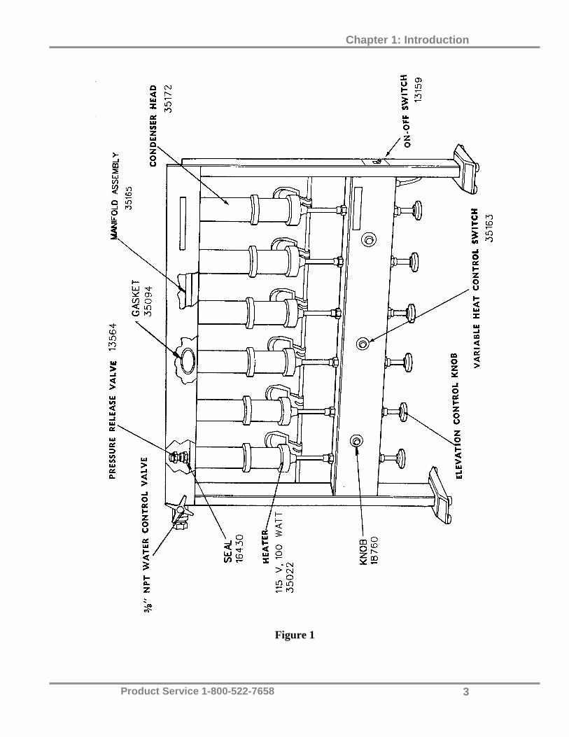
Refer to Figure 1 for the specific location of these components.
1. Manifold Assembly. This assembly is located at the top of the apparatus
and provides an even flow and distribution of water to the condenser
heads. Water exits through the water control valve, located on the upper
left hand portion of the unit. And flows through the manifold assembly,
depositing cool water in the condenser head system.
2. Pressure Release Valve. These valves are located at the top of the
manifold above each of the condensers. It provides an escape for excess
gaseous pressure which may build up in the condenser. The valves
automatically reset themselves to assure a closed system of extraction.
3. Condenser Head System. These cylindrical shaped condensers located
above each heater provide an essential part of the extraction process. The
solvent vapor rises from the boiling solvent and reaches a point inside the
condenser head coming into contact with metal cone shaped surface
which is cooled by water. The vapors condense and drip through the
sample held in the ceramic thimble, extracting the fat from the sample.
4. Heater System. Each 100 watt adjustable spring loaded heater provides
an even distribution of heat through the use of coiled heater wires
embedded in a ceramic material. The variable heat control switch located
at the front of the unit provides a variety of settings.
Chapter 1: Introduction
Product Service 1-800-522-7658 3
Figure 1

Product Service 1-800-522-7658 4
CChhaapptteerr 22::
IInnssttaallllaattiioonn
Preparation
The Goldfisch Extractor is shipped complete and fully assembled. The operating
parts shipped with the unit will be installed after the unit has been located in the
laboratory area.
Location
Choose a location in the laboratory which has a convenient 115 volt A.C. outlet,
an unrestricted 3/8" NPT cold water supply and drain facilities of at least 3/4"
NPT. Caution: The Goldfisch Extractor should be operated inside an explosion
proof hood with proper airflow to handle the extremely flammable solvents that
are used during the Goldfisch Extractor’s normal operation.
Utility Connections
(1) Once the unit has been placed in its final location, connect the cold water
supply to the 3/8" NPT control valve water fitting on the upper left.
(2) Connect the 3/8" NPT control valve on the upper right to an open drain of
sufficient size (3/4" IPS or larger) to accommodate the cooling water.
Cooling water should be a minimum of .75 gal/min or 2.8L/min for flow
(55 °F (13 °C) or less is preferable).
(3) Plug the unit into an electrical outlet.
Initial Start-Up and Check Out
Turn main power and variable heat control switches on. Make sure all heating
elements heat properly. Wait two to three minutes.

Chapter 2: Installation
Product Service 1-800-522-7658 5
Gasket Assembly Remove contents of the operating parts package which should be taped to the unit.
Assemble the gasket, wave washer, retaining ring and glassware according to
assembly drawing instructions as shown in Appendix A. Hand tighten the
retaining rings to achieve vapor seal.
Turn water on and make sure there is an even flow leaving the unit.
Product Service 1-800-522-7658 6
CChhaapptteerr 33::
NNoorrmmaall OOppeerraattiioonn && RRoouuttiinnee
MMaaiinntteennaannccee
Summary of Operation The Labconco extractor reduces extraction time from 16 hours to about four
hours through its efficient refluxing system. The operation is carried out by
using a Pyrex® beaker as the solvent chamber. The procedure involves
placing the samples between the boiling solvent and a cold surface. As
boiling continues, the solvent vaporizes, condenses on the cold surface and
washes back through the samples to the boiling solvent below.
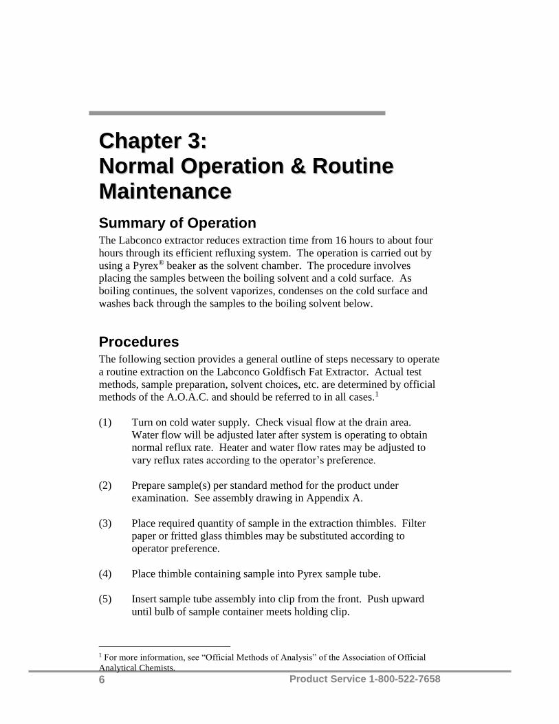
Procedures The following section provides a general outline of steps necessary to operate
a routine extraction on the Labconco Goldfisch Fat Extractor. Actual test
methods, sample preparation, solvent choices, etc. are determined by official
methods of the A.O.A.C. and should be referred to in all cases.1
(1) Turn on cold water supply. Check visual flow at the drain area.
Water flow will be adjusted later after system is operating to obtain
normal reflux rate. Heater and water flow rates may be adjusted to
vary reflux rates according to the operator’s preference.
(2) Prepare sample(s) per standard method for the product under
examination. See assembly drawing in Appendix A.
(3) Place required quantity of sample in the extraction thimbles. Filter
paper or fritted glass thimbles may be substituted according to
operator preference.
(4) Place thimble containing sample into Pyrex sample tube.
(5) Insert sample tube assembly into clip from the front. Push upward
until bulb of sample container meets holding clip.
1 For more information, see “Official Methods of Analysis” of the Association of Official
Analytical Chemists.

Chapter 3: Normal Operation & Routine Maintenance
Product Service 1-800-522-7658 7
(6) Place solvent of proper type and quantity into beaker. A quantity of
25 to 35 ml of solvent is normally sufficient for an estimate 3 to 4
hours of refluxing.
(7) Assemble beaker to retainer ring with the wave washer inserted and
twist to lock securely in place. After beaker is locked in place, pull
down elevation control knob and twist ¼ turn to the left. Raise
control knob to “catch” position and again twist ¼ turn to the left.
Slowly allow heater to rise against bottom of flask. DO NOT let go
of knob until heater is in position against beaker.
(8) Select heat rate required using panel control switch(es). Control is
provided for full range of power with the “HIGH” position providing
both heaters with approximately 100 watts each. Control position “5”
provides approximately 35 watts each.
(9) Turn the main power switch, located on the right side, to the ON
position. Switches on the panel each control two heaters.
NOTE: If only one extraction is being made, the adjacent (or
companion) heater, operating on the same panel switch, should be
loaded with a beaker of solvent or water to “load” the heater and
increase its service life.
(10) Pre-heating the heaters for about 8 to 10 minutes prior to starting
samples will reduce waiting time for start of refluxing.
(11) Water flow rate through the condenser head system can be regulated
to provide a wide range of reflux rates, when used alone or in
combination with heater control selections.
NOTE: If water flow rate is reduced too much, solvent will be lost in
the beakers. A condenser without flow rate will permit solvent to
escape through the pressure relief valves.
(12) When extraction is completed, place heater covers on heaters to
prevent solvent from coming into contact with the hot heater.
Remove sample tubes, replace with reclaiming tubes and remove
heater covers. Heat transfers solvent into the reclaiming tube, leaving
oil in the beaker.
(13) Drying of the extract is accomplished efficiently with a special swing
beaker holder (one holder behind each heater assembly) which
inclines the beaker at a slight angle in the warm air above the heater
assembly. When all but the last few milliliters of solvent is
evaporated, the beaker is placed in a drying oven, weighted and
compared to the tare weight of the beaker. Weight difference is the
amount of extracted material.

Chapter 3: Normal Operation & Routine Maintenance
Product Service 1-800-522-7658 8
(14) Heater covers are provided to prevent solvent from coming into
contact with the hot heater. Use covers when removing or attaching
beakers to condenser heads.
(15) The Labconco Fat Extractors are suitable for carrying out the indirect
Method of Fat Extraction (also known as “Crude Fat Extraction”).
This procedure requires the determination of moisture, followed by
extraction of the dried material, with the loss reported as the ether
extract.
Official methods should be referred to for specific test procedure of
the indirect method in all cases.
Maintenance All of the parts contained in the operating parts package are routine
maintenance items. It is suggested that additional supplies of these items be
kept in stock. Items such as gaskets or beakers occasionally wear out or
break and need to be replaced. You may order these through your local
laboratory apparatus dealer or by contacting Labconco Corporation. Be sure
to specify the Labconco part number when ordering. If contacting Labconco
directly, please furnish the name of the dealer from whom you purchased the
equipment.

Product Service 1-800-522-7658 9
AAppppeennddiixx AA::
RReeppllaacceemmeenntt PPaarrttss
PART # QTY DESCRIPTION
12726 1 Pilot light
13516 1 Valve, needle, water
13159 1 Switch, mercury, toggle single pole, 115 volt, 15 amp
13564 1 Valve, pressure relief
35094 1 Gasket, outer condenser shell
30139 1 Wire, No. 18, stranded nickel with braided glass cover for
heater harness and lead, 15' length
35167 Wiring harness – 6 unit
35022 1 Heating element, 115 volt, 110 watt
35163 1 Switch, infinite control
35046* Pkg. of 6 Beaker, glass (Pyrex), tall form, 5' high
35053 Pkg. of 6 Beaker, glass (Pyrex), 100 cc, 3 1/4" high
35054 Ring, beaker
35059 Pkg. of 6 Extraction thimble, 22 x 80 mm
35061 Pkg. of 6 Sample tube container (thimble holder), glass (Pyrex)
35062 Pkg. of 6 Reclaiming tube, glass (Pyrex)
35160 Pkg. of 6 Gasket, condenser, upper
35067* 1 Sample tube container (thimble holder), stainless steel
35185 1 Heater cover
35191 6 Req’d. Wave washer – Beaker seal
35120 Spring, compression heater push rod
35172 Condenser assembly
*Not furnished as standard equipment, but offered as an accessory.
Note: When ordering replacement parts, specify the Labconco equipment
serial number.

Appendix A: Replacement Parts
Product Service 1-800-522-7658 10

Product Service 1-800-522-7658 11
AAppppeennddiixx BB::
DDiimmeennssiioonnss
35.7"
26.9"
9"

Product Service 1-800-522-7658 12
AAppppeennddiixx CC::
SSppeecciiffiiccaattiioonnss
6-unit Goldfisch Fat Extractor Model No. 35001 operates on 115 volts, 50/60
Hz, (max.) at 5.2 amps. It is shipped complete with power cord and
grounded (3 wire) plug. Standard features are as follows:
1. Main power on-off.
2. Full range variable heat control switch. Each switch controls two heaters.
3. All stainless steel (Type 304) condenser assembly.
4. Pressure relief valves for each condenser.
Product Service 1-800-522-7658 13
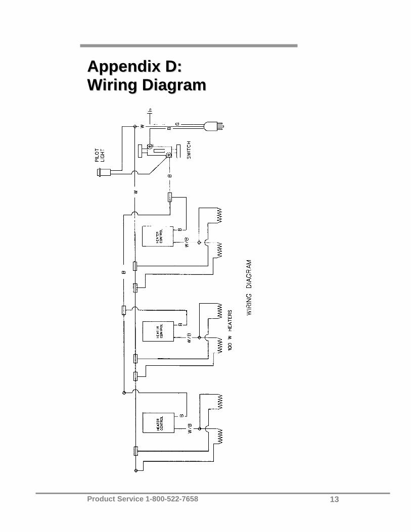
AAppppeennddiixx DD::
WWiirriinngg DDiiaaggrraamm