gmc truck/suv 2007-2011 high output intercooled system · gmc truck/suv 20072011 high output system...
TRANSCRIPT

GMC Truck/SUV 2007-2011 High Output Intercooled System
Installation Guide
The Intercooled Supercharging Experts!®
®

© 2012 Accessible Technologies, Inc.
Accessible Technologies, Inc. 14801 W. 114th Terrace
Lenexa, KS 66215 Phone: 913.338.2886
Fax: 913.338.2879 [email protected]
All rights reserved. Accessible Technologies Inc. hereby grants permission to use and reproduce this document for personal use, provided that all copyright information be retained. Reproduction of this document for unauthorized commercial use is strictly prohibited.
Information in this document is subject to change without notice.
ProCharger is a registered trademark and The Intercooled Supercharging Experts!TM and Designed to Blow Away the CompetitionTM are trademarks of Accessible Technologies, Inc. and may not be used without express permission.
Revised 5/12 Part Number PMGR1A-001 Rev. E Printed in the USA

GMC Truck/SUV 2007-2011 High Output System Installation Guide i
Introduction
Congratulations on purchasing your ProCharger® GMC Truck/Suv 2007-2011 High Output Intercooled System. Read this entire manual before you attempt to install your ProCharger kit. It is imperative that you follow all of the instructions in the order they appear in this installation guide. If you have any questions regarding any aspect of this installation, call us at (913) 338-3086.
For best results, we recommend reviewing the installation instructions beforehand, and following the installation instructions closely and in sequence. A detailed packing list has been provided to assist you in identifying the components of your ProCharger system.
Required Tools and Supplies• 3/8” Socket Set (standard & metric) • 3/8” Ratchet • 3/8” Hex Bit Set (allen head) • 5/16” Nut Driver • Floor Jack and Jack Stands • Open End Wrench Set (standard & metric) • Wire Stripper/Crimper • Locktite® 272 • Flat Screwdrivers • Phillips Screwdrivers • Plier Set • Electric Drill with 1/8" Drill Bit
Warning: Your supercharged GMC truck must always be run on 91 octane or higher gas.
IntroductIon
You should also have the following gauges available to properly check the finished installation and monitor your vehicle’s performance (especially for testing):• Manifold Boost Pressure Gauge • Fuel Pressure Gauge • Wide Band Oxygen Sensor and Gauge
Gauges should be of a type that can be read from the cockpit while performing a wide-open throttle road test. Cockpit or hood-mounted gauges are preferable. In order to obtain usable readings, the gauges should measure pressure at the intake manifold and fuel rail. IF VEHICLE DOES NOT MAINTAIN PROPER FUEL PRESSURE, DECREASE THROTTLE APPLICATION IMMEDIATELY. In some cases, extra vehicle modifications can strain the stock fuel pump. If your vehicle has difficulty retaining adequate fuel pressure, contact ATI ProCharger about the availability of an upgraded fuel system.
The engine on which the ProCharger® is to be installed should retain the factory compression ratio. If it has been modified in any way, please consult ProCharger staff before proceeding with the installation. This supercharger system is intended for use on STOCK, strong, well-maintained engines/transmissions. Installation on a worn or troublesome powertrain should be reconsidered. ATI PROCHARGER WILL NOT BE HELD RESPONSIBLE FOR DAMAGE TO A VEHICLE’S POWERTRAIN. ATI ProCharger is not responsible for ECM tuning/programming on non-stock vehicles. ATI PROCHARGER recommends verifying that your vehicle has current ECM updates from the vehicle manufacturer before installation.
For best performance and reliability, always use premium grade fuel (91 octane or higher) and listen closely for signs of detonation, which might sound like ball bearings rolling around in a tin can. IF DETONATION SHOULD OCCUR, OR IF YOU ARE UNSURE WHETHER WHAT YOU’RE HEARING IS DETONATION, DECREASE THROTTLE APPLICATION IMMEDIATELY and please consult ATI ProCharger staff. Detonation should not be an issue with a properly installed intercooled supercharger system, though OEM factory-shipped engine and parts inconsistencies are possible on any vehicle.

ii GMC Truck/SUV 2007-2011 High Output System Installation Guide
Introduction
table of contents
Introduction .................................................................................................................................. i
Table of Contents ..........................................................................................................................ii
Getting Started ............................................................................................................................ 1
Crank Pulley Pin Kit (optional) ..................................................................................................... 7
ProCharger Head Unit ................................................................................................................. 8
Intercooler and Tubing ............................................................................................................... 12
Air Inlet and Bypass Valve .......................................................................................................... 22
Crank Case Ventilation ............................................................................................................... 24
Fuel Injector Replacement ......................................................................................................... 25
Flow Charger Installation ........................................................................................................... 26
Reprogrammed ECU Installation ................................................................................................ 30
Installation Review/Safety Check ............................................................................................... 31
Operation and Maintenance ...................................................................................................... 32
Limited Warranty ....................................................................................................................... 34
ProCharger Extended Coverage ................................................................................................ 35
Notes ......................................................................................................................................... 36
For complete system installations, please review the ECU removal/reprogramming instructions (Getting Started), Fuel Injector Replacement and Flow Charger Installation sections to ensure you have the proper components to complete the installation. Tuning for this vehicle is a multi-step process that should be initialized before the installation has begun. If there are any questions about this process, or any other step during your installation, please call ProCharger Technical Service at 913-338-2886.

GMC Truck/SUV 2007-2011 High Output System Installation Guide 1
Getting Started
1 Remove the gas cap to relieve fuel tank vapor pressure.
2 Remove the fuel pump fuse from the fuse block. Crank the engine for a few seconds to bleed fuel pressure from the fuel lines. The engine should not start at this point. Replace the fuse.
Note: If your vehicle does not utilize a fuel pump fuse (located in the fuse block found in the engine compartment), place a rag under the schrader valve (passenger's side fuel rail), remove the cap on the valve, press the center pin to relieve fuel pressure, and place the cap back onto the valve.
3 Disconnect the negative battery cable from the battery.
4 Remove the plastic engine cover by pulling firmly upward.
5 Remove the ECU from it's bracket, located by the driver's side frame rail, and then remove the three (3) bolts (2 upper, 1 lower) to remove the ECU bracket itself with a 10mm wrench. Disconnect the two ECU connectors.
Note: Refer to the supplied forms found with these instructions for more information on tuning.
ECU Bracket
GettInG started
Schrader Valve

2 GMC Truck/SUV 2007-2011 High Output System Installation Guide
Getting Started
6 Unplug the Mass Airflow (MAF) sensor, remove the sensor from the stock air filter box and throttle body inlet tube, and set aside.
Note: 2009 model year trucks utilize a cartridge style MAF sensor. Unplug the harness leading to the MAF sensor. Using a Phillips screwdriver, remove the (2) screws securing the sensor to the airbox, and remove the assembly from the vehicle.
7 With a 5/16" nut driver, remove both the throttle body inlet tube from the throttle body and the clips on the upper radiator hose and set aside. Disconnect the PCV hose from the passenger's side valve cover.
8 Remove the plastic air filter box by lifting upward with a small amount of force.
Mass Airflow (MAF) Sensor
Throttle Body Inlet Tube Removed
Air Filter Box

GMC Truck/SUV 2007-2011 High Output System Installation Guide 3
Getting Started
9 With a 10mm socket and ratchet, remove the four (4) bolts from the black air filter box bracket on the passenger's side, and remove the bracket.
Note: We suggest replacing your factory plugs with Autolite AR103 spark plugs gapped at 0.035" at this time. These are one heat range colder than a factory spark plug.
10 With a 15mm socket and 3/8" ratchet, pull back on the factory spring tensioner and remove the factory serpentine drive belt.
11 Detach and remove the front fan shroud by removing the two (2) upper bolts from either side with a 13mm socket and ratchet.
12 Disconnect the clamps towards the bottom of the shroud assembly.
13 Disconnect the two (2) electric fan connectors at the bottom of the fan motors. Remove the push pin on the driver's side that mounts the AC lines to the fan shroud. Also, remove the (2) transmission cooler line bracket bolts located on the passenger's side radiator shroud with a 10mm socket. At this time, remove the fan by pulling it up and out of the engine compartment.
Tech Tip: Removing the fan will make it easier to install the supercharger bracket and bolts.
Air Filter Box Bracket
Factory Serpentine Drive Belt
Fan Shroud Bolts

4 GMC Truck/SUV 2007-2011 High Output System Installation Guide
Getting Started
14 Remove the two (2) bolts from the small factory splash panel on the driver's side frame rail using a 13mm socket and ratchet. This piece will not be reused.
15 With an appropriately rated automotive jack, lift up the front of the vehicle and secure with jack stands.
16 Remove the four (4) bolts securing the lower front splash panel with a 15mm socket and ratchet. Retain the bolts for use later in the installation. The lower front splash panel will not be reused.
17 With a 15mm socket and ratchet, remove the three bolts attaching the alternator/power steering bracket to the driver's side cylinder head, and the two alternator bolts. These five points will be the mounting platforms for the ProCharger main bracket.
Small Factory Splash Panel
Lower Front Splash Panel
Main Bracket Mounting Points

GMC Truck/SUV 2007-2011 High Output System Installation Guide 5
Getting Started
18 The lower passenger's side splash panel may need to be removed or trimmed to make room for the intercooler tubing. If you choose to remove it completely, fasten the inner fender well with a zip tie or similar device to keep the fender from flapping during normal driving. Otherwise, remove the (2) 10mm fasteners (1 upper, 1 lower), and the 2 push pins (1 upper, 1 in the inner fender well) that attach the plastic to the inner fender well, trim the plastic as shown, and re-install.
Stock Passenger's Side Splash Panel
Trimmed Passenger's Side Splash Panel

6 GMC Truck/SUV 2007-2011 High Output System Installation Guide
Getting Started
2007-2009 SUV's Only
Note: If installing on a 2007-2009 truck, proceed to the next section.
19 To allow the hood to close properly with the supercharger installed, replace both of the stock hood springs/hinges with the new heavy-duty hood springs included with your system.
Tech Tip: Springs may require two (2) people to install.
20 Attach the bottom part of the springs to the fender well first. Then (forcefully) bend the spring to align the hood with the top mounting position at the other end of the spring. Do not over-tighten the top bolt.
21 Once the new springs are installed, remove the stock gas-charged strut/hood prop. Make sure the hood aligns correctly after both hinges are installed and make adjustments as needed for symmetry.
Note: If you have trouble installing the new springs, you may choose to retain the “gas-charged strut” (hood prop) instead, though you will have to disconnect it every time you close the hood in order for it to clear the installed supercharger.
Stock Gas-Charged Strut/Hood Prop
Heavy Duty Hood Hinges (Passenger's Side)

GMC Truck/SUV 2007-2011 High Output System Installation Guide 7
Crank Pulley Pin Kit
Note: Pinning the balancer to the crankshaft is recommended.
1 Raise the front of the vehicle using car ramps, jackstands, or a vehicle lift.
2 Remove the factory harmonic balancer retaining bolt using a 24mm socket and impact wrench or breaker bar.
Tech Tip: Using a torch to heat the flange on the crank pulley bolt makes removal easier. There is an adhesive on the back of the flange which helps retain the bolt. Heating this breaks the adhesion.
3 Install the harmonic balancer pinning tool using the supplied M16 hex bolt.
4 Tighten the bolt to hold the tool in place and prevent spinning during the drilling process.
5 Tape the supplied 1⁄4” HSS drill bit 15⁄8” from the tip. Using this taped bit, drill a hole in the crankshaft and harmonic balancer, stopping at the tape edge. The hole will be centered on the OD of the crankshaft. Do not drill deeper than 0.800” into the face of the crankshaft.
6 Remove the pinning tool and set aside. Clean the chips from inside the drilled hole and the surrounding area throroughly.
7 Install the supplied 1/4” OD x 0.75” long stainless steel dowel pin in the hole (tapping the pin with a rubber mallet is acceptable). Re-install the crank pulley bolt and tighten to 40 ft-lbs plus an additional 120º.
crank Pulley PIn kIt
(oPtIonal)
Crankshaft and harmoniC BalanCer drill Jig
Harmonic Balancer Pinned to Crankshaft

8 GMC Truck/SUV 2007-2011 High Output System Installation Guide
ProCharger Head Unit
1 With a 17mm socket and ratchet, attach the billet main bracket, shown in exploded view below, through the factory alternator/power steering bracket to the driver's side cylinder head using the three (3) supplied M10 x 180 hex bolts, washers and 2.425" long spacers. Do not tighten at this time.
ProcharGer head unIt
Exploded View of the ProCharger Bracket System

GMC Truck/SUV 2007-2011 High Output System Installation Guide 9
ProCharger Head Unit
2 With a 17mm socket and ratchet, install two (2) M10 x 150 hex bolts through the billet main bracket to the alternator/power steering bracket using the 1.650" long spacers. The mounting points for the hex bolts are the alternator bolt holes.
Tech Tip: Due to the factory bushings that align the alternator to its bracket, the alternator spacers have been counterbored on one side to allow for the spacers to lie flat against the alternator bracket face.
3 Install the supplied 6 rib belt, making sure the belt is located below the 1.650" long spacer. Slide the belt between the main bracket and factory idler pulley. Route the belt under the factory idler pulley and over the alternator pulley.
4 At this time, fill your ProCharger with the supplied oil (6 ounces for a P1SC-1 or D1SC).
5 Tighten and torque all five (5) bolts supporting the main bracket to the alternator/power steering bracket.
6 Attach the ProCharger to the sub-bracket using three (3) 5/16"-18 x 5/8" hex bolts and washers, and one (1) 3/8"-16 x 3/4" hex bolt and washer. Tighten/torque these bolts.
Counterbored Alternator Spacers
Belt Installation
Sub-Bracket

10 GMC Truck/SUV 2007-2011 High Output System Installation Guide
ProCharger Head Unit
7 Place the ProCharger and sub-bracket assembly behind the main bracket and position the sub-bracket assembly so it’s fastening points align with the main bracket. Leave the idler pulley off temporarily. You can re-install this pulley by hand after the serpentine belt is correctly installed. Refer to the exploded view on page 7 for bolt and spacer placement.
8 Using a 9/16" wrench, socket and ratchet install two (2) 3/8"-16 x 3" hex bolts with washers through the main bracket and the two (2) 1.650" spacers. The lower bolt will require a lock nut on the back side and the upper bolt will thread into the supercharger.
Tech Tip: The compressor housing on the back side of the supercharger may need to be rotated slightly for clearance. You may loosen the small 3/16" allen bolts along the outer diameter of the supercharger, but you MUST tighten/torque them once the outlet is rotated to the correct position. Failure to do so could cause damage and/or void the warranty.
9 With a 15mm socket and ratchet, pull back on the factory tensioner and install the serpentine belt. With the tensioner still pulled back, slide the idler pulley and two (2) idler bushings down and into place between the sub-bracket and main bracket.
Sub-Bracket Assembly Installed
Idler Pulley

GMC Truck/SUV 2007-2011 High Output System Installation Guide 11
ProCharger Head Unit
10 Install a 5/16"-18 x 3" hex bolt with washer through the main bracket, idler, and into the supercharger. Tighten/torque all fasteners.
11 Use the diagram below to route the serpentine belt (4.00" supercharger pulley = 114.50" long 6 rib belt.
Tech Tip: A brand new belt will be considerably tighter immediately after installation, but will loosen and stretch after approximately 50 miles of use, and may need to be re-tightened.
12 Re-install the fan and fan shroud by reattaching the clamps, two (2) upper bolts, and the electric fan connectors.
Serpentine Belt Installed

12 GMC Truck/SUV 2007-2011 High Output System Installation Guide
Intercooler and Tubing
Intercooler and tubInG20
07-2
008
2-c
or
e In
ter
co
ole
r s
ch
em
atI
c

GMC Truck/SUV 2007-2011 High Output System Installation Guide 13
Intercooler and Tubing
2007
-200
8 3-
co
re In
ter
co
ole
r s
ch
em
atI
c

14 GMC Truck/SUV 2007-2011 High Output System Installation Guide
Intercooler and Tubing
2009
+ 2
-co
re In
ter
co
ole
r s
ch
em
atI
c
222
270

GMC Truck/SUV 2007-2011 High Output System Installation Guide 15
Intercooler and Tubing
2009
+ 3
-co
re In
ter
co
ole
r s
ch
em
atI
c
222
270

16 GMC Truck/SUV 2007-2011 High Output System Installation Guide
Intercooler and Tubing
1 With a 15mm socket and ratchet, install the rear sheet metal intercooler bracket (black) to the front suspension cross-member using the provided fasteners and spacers. The rear mounts using the factory 15mm bolts, the front utilizes the provided spacers, 3/8-16 bolts and washers.
2 Using the remaining two (2) factory splash panel bolts, install the two supplied front intercooler mounting straps (silver). These must be bent by hand so that they point straight down.
Front Intercooler Mounting Straps
Rear Sheet Metal Intercooler Bracket

GMC Truck/SUV 2007-2011 High Output System Installation Guide 17
Intercooler and Tubing
3 You may need to mark off the mounting holes with a marker and then drill out the holes in order to install the air scoop and support strap to the intercooler.
4 With a 7/16" wrench and socket, install the black rubber air scoop and the aluminum support strap to the intercooler, using the nine (9) supplied 1/4"-20 x 1" hex bolts, lock nuts and flat washers.
Tech Tip: To ensure you get the coolest charge air temperatures, try to minimize obstructions to the intercooler that might restrict air flow.
Mark Off Mounting Holes
Black Rubber Air Scoop

18 GMC Truck/SUV 2007-2011 High Output System Installation Guide
Intercooler and Tubing
5 Using a 9/16" wrench, socket and ratchet, install the intercooler to the front two mounting straps and the rear mounting bracket using the four (4) 3/8"-16 x 1-1/4" bolts.
6 Tighten/torque all intercooler mounting bolts.
Tech Tip: To ease installation, leave hose/tube clamps loose until all hoses and tubes are rotated and fitted correctly.
7 With a 5/16" nut driver, install a rubber 4" to 3-1/2" reducer from the throttle body to the upper tube using a #56 hose clamp and a #64 hose clamp. For aesthetic purposes, you may choose to route the coolant reservoir hose under this long tube. Make sure to slide the hose sheathing underneath the tube to protect the hose from wear.
Note: The hose clamps are labeled with part numbers in order to identify the tube size they are associated with. For example: (#52 = 3" hose/tube), (#56 = 3-1/2" hose/tube), (#64 = 4" hose/tube).
Front Mounting Straps
Rear Mounting Bracket
Rubber Reducer And Upper Tube

GMC Truck/SUV 2007-2011 High Output System Installation Guide 19
Intercooler and Tubing
(2007-08 MODELS ONLY)
8 Place the MAF sensor onto the 3-1/2" rubber 90° elbow using #56 hose clamps (this is a tight fit). The arrow on the MAF sensor must point towards the elbow.
9 With a 5/16" nut driver, install the MAF sensor and elbow assembly to the end of the upper tube with a #56 hose clamp, with the MAF inlet facing down. In order to preserve the integrity of the custom programming, the MAF sensor must be rotated with the electrical connection facing the coolant reservoir.
10 Reattach the MAF electrical connection.
11 Attach the remaining rubber 4" to 3-1/2" reducer to the inlet of the MAF sensor with a #56 and a #64 hose clamp.
12 Install the 3-1/2" to 3" extended 90° steel tube from the MAF rubber reducer downward, with the 90° end aimed toward the intercooler below. This will not yet line up exactly with the intercooler outlet.
MAF Sensor Installed On Rubber 90° Elbow
MAF Sensor And Elbow Assembly
MAF Electrical Connection

20 GMC Truck/SUV 2007-2011 High Output System Installation Guide
Intercooler and Tubing
(2009 MODELS ONLY)
8 Mount the MAF sensor into the upper tube using the provided M4 screws. Plug the electrical harness into the sensor.
9 Connect the provided 3" long 3-1/2" diameter hose coupler onto the upper tube using a #56 hose clamp.
10 Mount the provided steel 90° elbow to the 3-1/2" diameter hose coupler using a #56 hose clamp.
11 Slide the provided 7" section of 3-1/2" diameter hose onto the steel 90° elbow and secure using a #56 hose clamp.
12 Install the 3-1/2" to 3" extended 90° steel tube from the rubber coupler downward, with the 90° end aimed toward the intercooler below. This will not yet line up exactly with the intercooler outlet.
MAF Sensor Installed
Steel 90° Elbow Mounted To Upper Tube

GMC Truck/SUV 2007-2011 High Output System Installation Guide 21
Intercooler and Tubing
(Intercooler Installation Cont.)
13 Connect the offset double 45° rubber hose from the intercooler outlet plenum to the 90° metal tube using #52 hose clamps to secure.
14 With a 5/16" nut driver, install the rubber 45° elbow to the outlet of the supercharger. Connect the straight steel bypass tube, bung facing upwards, to the 45° elbow. Secure all connections with #52 hose clamps.
15 Install the second rubber 45° elbow, facing down, to the bypass tube (near the outside driver's side frame rail). Secure with #52 hose clamps.
16 Connect the 3" x 10" long steel tube, to a 3" rubber 90° hose. Attach the steel tube to the 45° elbow and the 90° rubber hose to the intercooler inlet plenum. Secure all connections with #52 hose clamps.
17 Check and tighten all hose clamps.
Note: If installing a 2 core intercooler, your system will include an additional 3" x 3" tube, a short section of 3" rubber hose, and 2 additional #52 hose clamps. Slide the hose onto the intercooler inlet, followed by the tube. Connect the tube to the 90° rubber hose. Secure using the provided hose clamps.
Double 45° Rubber Hose
Rubber 45° Elbow With Bypass Tube
45° Elbow With 10" Long Steel Tube

22 GMC Truck/SUV 2007-2011 High Output System Installation Guide
Air Inlet and Bypass Valve
aIr Inlet and byPass ValVe
1 Using a 5/16" nut driver and two (2) #64 hose clamps, install the air filter onto the inlet elbow, and connect to the supercharger inlet, as seen in the diagram on the right. The surge return bung should aim towards the master cylinder slightly.
2 Install the Proflow surge valve as seen in the diagram, with the appropriate hoses and #20 hose clamps. Some trimming may be required for hoses to fit correctly. Air Filter/Inlet Elbow Assembly

GMC Truck/SUV 2007-2011 High Output System Installation Guide 23
Air Inlet and Bypass Valve
3 Attach one end of the supplied 3/16" vacuum hose from the brass port on the surge valve and route it over to the passenger's side of the intake manifold.
4 The manifold vacuum source can be found on the passenger's side of the intake manifold. This vacuum source/port can be enabled by breaking off the tip of the plastic tab with pliers. Use caution not to break off the entire tab.
5 Attach the other end of the vacuum hose to this vacuum port.
Tech Tip: You can test the Proflo valve linkage by hand to make sure the valve opens and closes smoothly. Driveability problems can often result from incorrect operation of the valve.
Manifold Vacuum Source
Proflo/Vacuum Hose
Manifold Vacuum Source/Vacuum Hose

24 GMC Truck/SUV 2007-2011 High Output System Installation Guide
Crank Case Ventilation
crank case VentIlatIon
1 On the passenger's side valve cover, next to the oil fill neck, there is a 3/8" crank case vent/port.
2 Attach the 2.5' long 3/8" hose to the vent/port, route it to the driver's side and attach it to the air inlet tube bung.
3 Remove the plastic air tube running from the top of the intake manifold to the rear of the driver's side valve cover. Connect the 1.5' section of 3/8" hose to these two points. Cut the line in the center, and insert the provided check valve. Verify that the arrow on the check valve points towards the intake manifold.
Note: 2009 model year trucks utilize an o-ring seal for the PCV line on the intake manifold. You must retain the o-ring end of the factory PCV tube that plugged into the manifold by cutting the plastic tube and inserting the provided rubber hose onto the cut end of the tube. Run the other end of the hose to the driver's side valve cover per Step 3.
Intake Manifold PCV Line O-Ring Seal
Check Valve
Crank Case Vent/Port

GMC Truck/SUV 2007-2011 High Output System Installation Guide 25
Fuel Injector Replacement
fuel Injector rePlacement
Note: This section only applies to full systems, which include upgraded fuel injectors. If you do not have a full system, upgraded fuel injectors will be required before starting the vehicle.
1 Verify that the fuel system has been depressurized.
2 Disconnect the fuel injector electrical connectors one at a time, labeling them by their corresponding injector location. To disconnect, remove retainer clips (A) and set aside for reassembly later.
3 Remove the four (4) fuel rail attaching bolts with an 8mm socket and ratchet.
4 Remove injector retainer clips (B) to release each injector from the fuel rail. Remove the old injectors and set aside.
5 Lubricate each new injector o-ring seal with several drops of clean engine oil.
6 Install each injector onto the fuel rails, making sure that the injectors are rotated to line up with their corresponding electrical connectors.
7 Using Loctite 272™ (high temperature thread locker) or equivalent, re-install the fuel rail bolts with spacer shims under each of the four mounting points.
8 Reattach all connections and clips.
Warning: Never re-use fuel injector o-ring seals, as they lose elasticity over time and could cause a fuel leak and/or potential fire.
Injector Retainer Clips(Factory Injector Shown Above)
RETAINERCLIP (A)
RETAINERCLIP (B)
Fuel Rail Bolts/Shims

26 GMC Truck/SUV 2007-2011 High Output System Installation Guide
Flow Charger Installation
E4
Note: This section only applies to full systems, which include the Flow Charger boost-a-pump. Flow Charger's are only required for 2007 & 2008 6.0L and 6.2L engines. If you do not have a full system, additional fuel system modifications may be required. If you have a 4.8L or 5.3L engine, or a 2009-2011 6.0L/6.2L, skip to the next section.
1 If you have not already done so, disconnect the negative battery cable. Remove the cover from the factory fuse panel, located on the top of the driver's side wheel well.
2 Carefully flip the two gray handles up toward's the middle. This should unlock the panel cover so it can be removed, exposing the fuse block connectors.
3 Undo the tabs to unfasten the top left (black) fuse block connector, exposing the wiring underneath it.
4 The illustration (lower right) identifies location E4 (the red wire with a white stripe) which is the “FSCM” location, where the Flow Charger will splice into.
flow charGer InstallatIon
Fuse Panel
Fuse Block Connector

GMC Truck/SUV 2007-2011 High Output System Installation Guide 27
Flow Charger Installation
5 Cut and strip both ends of the red/white E4 wire, leaving approximately 1.5" of exposed wire on each end.
Note: If the wires/fuses are organized or colored differently than described in this section, please call ATI ProCharger at (913) 338-2886 for the most up-to-date wiring information.
6 Attach the supplied red wire to the end of the red/white E4 wire on the black fuse block connector using a supplied wire connector.
7 Attach the supplied yellow wire to the end of the red/white E4 wire, which connects to the factory fuel pump, using a supplied wire connector.
8 Snap the black fuse block connector back into its original, top left postion.
9 Route the input and output power wires through the back and then around the right side of the fuse panel box. Screw the red wire along with the internal relay wire into the B+ terminal located on the Flow Charger. Screw the yellow wire into the PUMP terminal located on the Flow Charger.
E4 RED/WHITE WIRE
E4 FUSE BLOCK LOCATION
GROUND
BOOST REFERENCE WIRES
BOOST-A-PUMP
POWER IN WITH 30 AMP FUSE
POWER OUTTO FUEL PUMP
INTERNAL RELAY WIRE

28 GMC Truck/SUV 2007-2011 High Output System Installation Guide
Flow Charger Installation
10 Ensure that none of the prongs on the underside of the fuse panel are bent, and carefully re-install the panel back onto the box.
11 Lock the two gray handles back into their original positions and make sure the panel is fastened securely.
12 With an electric drill and 1/8" drill bit, use the supplied screws to mount the Flow Charger to the inner fender well, behind the driver's side headlight as shown.
13 Crimp the supplied ring terminal to the end of the supplied piece of black wire. Screw the wire into the Flow Charger ground terminal, and connect the ring terminal to a clean, metal ground source (any of the 3 battery tray fasteners located below the Flow Charger are sufficient).
14 Crimp the supplied ring terminals to the (2) boost reference wires.
15 Assemble the Hobbs switch by tightening the barbed fitting to the threaded end, and screwing the ring teminals that were crimped in the previous step to either side of the Hobbs switch as shown at right (wire colors do not matter for this step).
Warning: Double check the Flow Charger ground – if the ground is inadequate, the unit could be damaged.
Fuse Panel Cover
Flow Charger Installed
Hobbs Switch
GMC Truck/SUV 2007-2011 High Output System Installation Guide 29
Flow Charger Installation
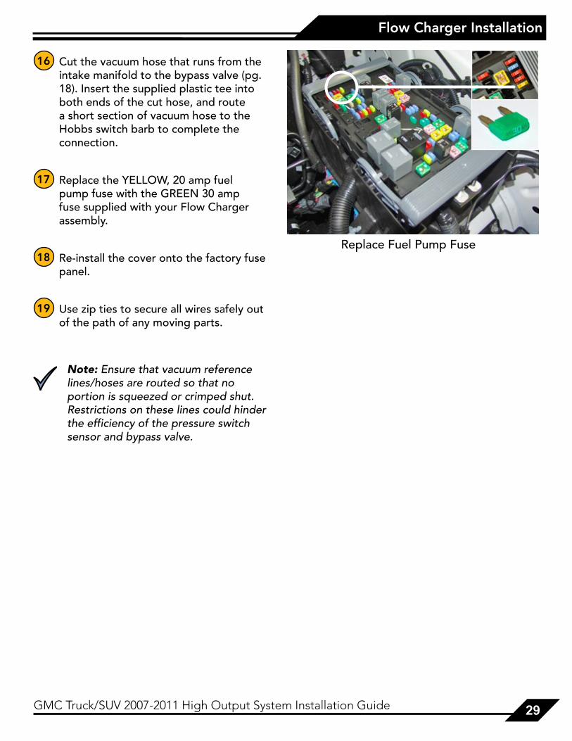
16 Cut the vacuum hose that runs from the intake manifold to the bypass valve (pg. 18). Insert the supplied plastic tee into both ends of the cut hose, and route a short section of vacuum hose to the Hobbs switch barb to complete the connection.
17 Replace the YELLOW, 20 amp fuel pump fuse with the GREEN 30 amp fuse supplied with your Flow Charger assembly.
18 Re-install the cover onto the factory fuse panel.
19 Use zip ties to secure all wires safely out of the path of any moving parts.
Note: Ensure that vacuum reference lines/hoses are routed so that no portion is squeezed or crimped shut. Restrictions on these lines could hinder the efficiency of the pressure switch sensor and bypass valve.
Replace Fuel Pump Fuse

30 GMC Truck/SUV 2007-2011 High Output System Installation Guide
Reprogrammed ECU Installation
1 Install the original black plastic ECU bracket into the upper front left threaded hole using (1) of the original 10mm fasteners (you will only use one fastener as opposed to the (2) that were removed).
2 Place the supplied spacer into the upper left rear threaded hole. Place the ECU on top of the spacer and align with one of the holes located on each corner of the ECU. Fasten the ECU to the vehicle using the supplied 6mm x 60mm bolt and washer. The bolt will go through the washer, followed by the ECU, then the spacer, and into the threaded hole.
3 Reattach the ECU connections.
Warning: Aftermarket chips/programmers for naturally aspirated motors advance timing at elevated RPM’s; this will cause detonation and engine damage if used with a supercharger. Many aftermarket chips and programmers also extend your rpm range. Since boost is related to engine rpm, this can produce excessive boost and engine damage. Boost figures for ProCharger® pulleys are rated at 5,700 rpm on a stock 6.2L Vortec V8 engine.
reProGrammed ecu InstallatIon

GMC Truck/SUV 2007-2011 High Output System Installation Guide 31
Installation Review/Safety Check
1 Reattach the gas cap and negative battery cable.
2 Check the new injectors for leaks by performing the following procedure:
A. Turn the ignition to the “on” position for 2 seconds; don’t start the engine!
B. Turn the ignition off for 10 seconds.
C. Turn the ignition to the “on” position.
D. Check for fuel leaks at both ends of each injector and at the fuel supply hose fittings.
3 Re-install the plastic engine cover.
4 Carefully review the entire installation. Examine fuel lines routed near moving parts and exhaust components to ensure that they are protected from chafing or abrasion, secure and free of twists and kinks. All wires and hoses should be firmly secured with clamps or wire ties.
5 Check and correct all fluid levels.
6 Start the engine and let it idle for a few minutes. Shut off the engine and check for fluid leakage, signs of rubbing parts, and other potential problems.
InstallatIon reVIew/safety check

32 GMC Truck/SUV 2007-2011 High Output System Installation Guide
Operation and Maintenance
oPeratIon and maIntenance
Cold StartingNever race your engine and ProCharger supercharger when your engine is cold. Allow the water temperature to climb into operating range for several minutes before driving above 2,500 rpm, to ensure adequate oil lubrication.
Fuel QualityWith a properly installed intercooled ProCharger supercharger system, detonation should not occur. For the best performance and reliability, use premium grade fuel (91 octane or higher). Listen for signs of detonation after refueling, and after replacement or modification of any fuel system component(s). If detonation occurs, reduce the throttle and locate the source.
Ignition System MaintenanceIf your spark plugs are more than a year old or have more than 10,000 miles logged, you should consider changing them before driving your vehicle under load. Spark plug wires should be changed if visibly damaged or when resistance exceeds factory specifications.
Air Filter MaintenanceYour air filters should be cleaned periodically, potentially as often as every 10,000 miles or 6 months, even though a service interval of 50,000 - 100,000 miles is quoted by the manufacturer under normal driving conditions. A clogged air filter will result in decreased boost levels and vehicle performance. Be sure to re-oil the cleaned filter before re-installing. Always operate your vehicle with an air filter, failure to do so may result in damage to your ProCharger supercharger and personal injury!
Belt ReplacementThe serpentine belt, which turns your ProCharger supercharger, will stretch after initial run-in, and should be retightened after the first hundred miles. Tighten the belt sufficiently to avoid slippage, but do not overtighten. Overtightening the belt could cause damage to the ProCharger supercharger’s precision bearings. When re-installing the belt, use the belt routing diagram in this manual. If you reuse a thrown belt and find that it needs frequent re-tightening, the belt is damaged and should be replaced. Gates Micro-V belts can be bought from ATI or from your local parts store.
ProCharger Oil Change IntervalsThe first oil change should be performed at 500 miles and at 6,000 mile intervals thereafter. Clean drain plug after every oil change. Drain oil by removing the drain plug. Clean off drain plug before re-installing.

GMC Truck/SUV 2007-2011 High Output System Installation Guide 33
Operation and Maintenance
Magnetic Drain Plug (hex head)
Sealed Plug (socket head)
Dipstick (flat head)
Sealed Plug (socket head)
ProCharger Oil LevelThe ProCharger supercharger’s oil level must be checked periodically to ensure the proper lubrication. The dipstick can be loosened using a flat blade screwdriver or a coin. When installed, the oil level should remain between the minimum (MIN) and maximum (MAX) indicators at all times.
Warning: Filling the ProCharger higher than the maximum level on the dipstick can lead to bearing and seal damage. The supercharger is a sealed unit and should not normally require the addition of oil between service intervals. If excessive usage is noted, the unit should be sent to ATI for inspection and repair. The dipstick fitting should be firmly tightened after changing or checking the oil level.
GeneralWhen removing the warning tag, be sure to retain the nylon washer. A spare nylon washer and o-ring is included. Use only the ATI supplied nylon washer and o-ring when servicing the oil dipstick and drain plug. A discoloration of the oil and residue on the drain plug may occur during the initial oil changes. This is normal and will gradually decrease. For the proper positioning of the ProCharger supercharger, the serial tag should be pointing upwards. Installing the ProCharger supercharger in another position will cause inadequate oiling and supercharger failure. If you have any questions about the maintenance of your supercharger, contact ATI.

34 GMC Truck/SUV 2007-2011 High Output System Installation Guide
Limited Warranty
lImIted warranty
Accessible Technologies, Inc. (ATI) provides a limited twelve (12) month warranty on the ProCharger supercharger against defects in materials and workmanship unless otherwise specified. This limited warranty starts on the date of original purchase from your local dealer, or date of shipment from the factory. This limited warranty coverage is extended only to the original owner and excludes hoses, sleeves, and electronic components manufactured by other companies. IF THE SUPERCHARGER’S DRIVE RATIO IS ALTERED IN ANY WAY FROM THE FACTORY SETTING, WARRANTY COVERAGE IS VOID. USE OF ANY PULLEY NOT MANUFACTURED OR SUPPLIED BY ATI VOIDS ALL WARRANTY COVERAGE. ATI’s warranty obligations are limited to the terms below:
ATI agrees to honor a warranty claim at its sole discretion and only after inspection at the ATI factory. No warranty will be honored if any part of the product is found to have been improperly installed, tampered with, mishandled, or misused in any way. Disassembly of the ProCharger supercharger or removal of the ProCharger supercharger’s serial plate voids all warranties. Claims for freight damages should be directed to the freight company.
If ATI’s limited warranty applies, your product will be repaired or replaced at ATI’s discretion and shipped back. If the limited warranty does not apply, ATI will advise you of the specific reason, cost of the repair, and delivery time. After advising you of this information we will, at your option, either proceed with repairs or return your product to you in the state in which it was received. In either case the product will be shipped to you, insured at replacement value. Therefore, you will pay the return shipping and insurance charges if ATI’s limited warranty does not apply to your product.
THE WARRANTY AND REMEDIES SET FORTH ABOVE ARE EXCLUSIVE AND IN LIEU OF ALL OTHERS, ORAL OR WRITTEN, EXPRESS OR IMPLIED. THE DURATION OF ANY AND ALL WARRANTIES ON THE PRODUCTS DISCUSSED ARE LIMITED TO THE PERIOD IDENTIFIED ABOVE. ATI IS NOT RESPONSIBLE IN ANY EVENT FOR DIRECT, SPECIAL, INCIDENTAL OR CONSEQUENTIAL DAMAGES. No ATI dealer, agent, or employee is authorized to make any modification, extension, or addition to this warranty.
To obtain service under this warranty you must do the following during the warranty period:
Phone ATI (913-338-2886) and provide us with the following information:
- ProCharger supercharger serial number. - Vehicle year, make, model, engine modifications, and other modifications. - Description of perceived issue.
If a solution to your issue can not be found after the above phone consultation, you will be assigned a return authorization number (RMA). You must then properly package and ship your product, at your expense, to the ATI factory. The product should be carefully packaged in a rugged box.
Include the following information inside the box with your product:
- Copy of your original invoice or receipt. - Name, address, and daytime telephone number. - Return authorization number (RMA). - Vehicle year, make, model, engine modifications, and other modifications. - Description of perceived issue.
Clearly mark the warranty claim number on the top and one side of the box in characters at least 2” tall. Properly package the product and ship it, prepaid and insured for the retail value of the component(s) being returned, to the following address:
Accessible Technologies, 14801 West 114th Terrace, Lenexa, Kansas 66215

GMC Truck/SUV 2007-2011 High Output System Installation Guide 35
ProCharger Extended Coverage
ProcharGer extended coVeraGe
The ProCharger Extended Coverage Program extends the ProCharger warranty coverage for an additional twenty-four (24) months, for a total of thirty-six (36) months or three years of coverage. This extended coverage applies to parts for the ProCharger supercharger head unit only and does not include other system components. With your extended coverage registration, you will receive two (2) additional boxes of ProCharger Supercharger oil.
Under the extended coverage program, Accessible Technologies, Inc. (ATI) will repair or replace any component within the supercharger head unit which is found to be defective. Only the supercharger head unit itself is included in the extended coverage.
Service under the extended coverage program is obtained through the same process as described in the Limited Warranty.
Race kits are not eligible for the ProCharger Extended Coverage Plan
To qualify for the ProCharger Extended Coverage:
• Only the original owner of the ProCharger supercharger is eligible.
• Completion of the Extended Coverage Registration Form is required, along with a $49 registration fee. This form must be completed in its entirety, and must be submitted along with payment within 30 days from the date of original purchase from your local dealer or date of shipment from the factory.
• Participants must have a ProCharger P-1SC, P-1SC-1, C1, or C2 supercharger head unit using the maximum warranted boost level. All terms and conditions within “The Limited Warranty” apply. Acts resulting in disqualification include but are not limited to the following:
- Disassembly or modification the ProCharger supercharger.
- Removal or attempted removal of the ProCharger drive pulley(s).
- Removal or attempted removal of the ProCharger supercharger serial number plate.
- Removal or attempted removal of the compressor housing or transmission case.
• Participants agree to properly maintain the ProCharger supercharger and provide proof of compliance with the following recommended maintenance:
- Change the ProCharger supercharger oil after the initial break-in period of 500 miles (automotive) or 15 hours (marine).
- Change the ProCharger supercharger oil every 6,000 miles after the initial break-in period.
- Use only the specified amount of ProCharger Supercharger oil in the ProCharger supercharger.
- Inspect and clean the magnetic drain plug at every ProCharger supercharger oil change.
- Check the ProCharger supercharger oil level frequently.

36 GMC Truck/SUV 2007-2011 High Output System Installation Guide
Notes

ProCharger Extended Coverage Program Registration Formcu
t al
ong
the
do
tted
line
cut
alo
ng t
he d
ott
ed li
ne
Name:_________________________________
Address:_______________________________
City:___________________________________
State:________________ Zip:____________
Daytime phone:_________________________
Evening phone:_________________________
E-mail:_________________________________
Age 18 - 24 25 - 34 35 - 44 45 - 54 55 and up
Income $15,000 - $29,000 $30,000 - $44,000 $45,000 - $69,000 $70,000 and up
What magazines do you read?
Car & Driver Car Craft Chevy High Performance Four Wheel and Off Road Hot Rod Motor Trend Muscle Mustangs and Fast Fords GM High-Tech Performance 5.0 Mustang Super Street Mustang Monthly Truck Trends Popular Hot Rodding Road & Track Super Chevy Truckin’ Street Truck
Date of Purchase:_______________________
Purchased From:_______________________
ProCharger Serial #:_____________________
Vehicle Year:___________________________
Vehicle Make:__________________________
Vehicle Model:_________________________
Please rank in order of importance starting with 1 being most important.
Which information sources most influenced your decision to purchase a ProCharger system?
___ Magazine advertising ___ Dealer recommendation ___ ProCharger Brochures ___ Witnessed performance on a car ___ Test drive ___ Magazine editorials ___ Friends ___ Conversations with ATI technicians ___ Web Site (please specify)___________ ___ Other (please specify)__________
What most influenced your decision to purchase a ProCharger system?
___ Reliability ___ Standard warranty ___ Extended coverage warranty ___ Performance ___ Quiet operation ___ Removability (ability to return car to stock) ___ Cost ___ Ease of Installation
Who installed your ProCharger system? Self Dealer Other ________________________ Have you own a forced induction system previously? Yes No If yes: Supercharger: Brand(s)_______________________ Vehicle(s)_____________________________
Turbocharger: Brand(s)_______________________ Vehicle(s)_____________________________
I have read and understand the policy for the ProCharger Extended Coverage Program. I have not and will not modify my ProCharger supercharger in any way during my participation in the extended coverage program. I have read and answered all questions on this form. I have enclosed my check for $49, payable to ATI, for enrolling my ProCharger supercharger (serial number indicated above) in the extended coverage program for an additional twenty-four (24) months beyond the standard limited warranty period of twelve (12) months.
Signature_____________________________________________ Date_____________________
Mail this completed registration form with a $49 check to ATI at: 14801 West 114th Terrace, Lenexa, KS 66215. If you have any questions, contact us at [email protected] or (913) 338-2886 8:30 AM - 5:30 PM CST, Monday - Friday.
Return this completed form and a $49 check within 30 days of original purchase.

this page intentionaly left blank

this page intentionaly left blank

Accessible Technologies, Inc. 14801 W. 114th Terrace
Lenexa, KS 66215 Phone: 913.338.2886
Fax: 913.338.2879 [email protected]
Accessible Technologies, Inc. ©2012 ATI, All Rights Reserved
Part Number PMGR1A-001 Rev. E
*PMGR1A-001*