gladiator - hawk measurement systems acoustic switch cleaner data... · gladiator acoustic switch...
TRANSCRIPT

A Higher Level of Performance
www.hawkmeasure.comFor more information, please visit >
GladiatorAcoustic Switch Series Auto Spray Cleaner
Data Sheet
OverviewSultan Acoustic Wave Series
2
Auto Spray CleanerGladiator Acoustic Switch Series
Concept
The Gladiator Acoustic Switch has received a firmware update to utilise the Relay 2 as a trigger mechanism to notify the user or activate a cleaning system based on time or conditions within the chute which require cleaning.
There are three software options using two different concepts. The first concept is based on total Gain used and the second is based on a Time interval.
The options are located in the Advanced menu as a sub menu for Relay2Action.
The selectable software options are as follows:
[Maintnce Chk] - The unit will switch on the relay when total Gain is greater than the CleanGainHigh % - the relay will switch off when Gain falls below CleanGainLow %.
[GainOpt Clng] - When total Gain exceeds the CleanGainHigh point the unit activates the relay for 1/2 of the On Delay time and then switches off. The unit will then count the Clean Time interval time before repeat the process until total Gain is below CleanGainLow point.
[TimeOpt Clng] - At every Clean Time interval the unit will switch on the relay for 1/2 of the On Delay time and then switch off.
Terminology Reference & Details
Gain Gain is a term used to describe the sensitivity of the unit. When conditions in a chute worsen then unit automatically increases Gain to maintain a full signal between each sensor.
The amount of Gain the unit is using is at any time a viewable diagnostic - While the unit is pulsing press the up or down arrow until the top line reads Gain. It’s current value will be also be on the top line.
Switch On Delay Delay before activating primary relay (Relay 1). Delay time adjustable in ‘Quickset’
Maintenance Check Use as a ‘pre alarm’ that the unit may require cleaning or maintenance.
Gain Option Cleaner Use to activate a water spray when the unit is using high amounts of gain to maintain its signal. Use the water spray to clear out crusting and cupping which can form over the sensor face. The spray duration will be half of the switch on delay time to avoid false trips. Recommend at least 3 second switch on delay.
The Clean Time interval is used if the first spray does not result in Gain falling below the low Gain point. The unit will wait for this time period until attempting the next spray.
Time Option Cleaner Use to activate a water spray using a timer interval only. The spray duration will be half of the switch on delay time to avoid false trips.
User Guide
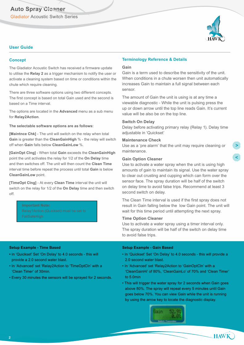
Setup Example - Time Based
• In ‘Quickset’ Set ‘On Delay’ to 4.0 seconds - this will provide a 2.0 second water blast.• In ‘Advanced’ set ‘Relay2Action to ‘TimeOptCln’ with a ‘Clean Timer’ of 30min.• Every 30 minutes the sensors will be sprayed for 2 seconds.
Setup Example - Gain Based
• In ‘Quickset’ Set ‘On Delay’ to 4.0 seconds - this will provide a 2.0 second water blast.• In ‘Advanced’ set ‘Relay2Action to ‘GainOptCln’ with a ‘CleanGainHi’ of 80%, ‘CleanGainLo’ of 70% and ‘Clean Timer’ to 5.0min• This will trigger the water spray for 2 seconds when Gain goes above 80%. The spray will repeat every 5 minutes until Gain goes below 70%. You can view Gain while the unit is running by using the arrow key to locate the diagnostic display.
Important Note: Relay1Action (Quickset) must be set to FailSafeHigh

OverviewSultan Acoustic Wave Series
3
Auto Spray CleanerGladiator Acoustic Switch Series
Use CAL as select / proceed / save Arrows to scroll between menu options
CALSensor Value
CALUnlock 0 Quickset
CALApp TypeCal MountSwitch PointOn Delay AdjOff Delay AdjRelay Action
CALOn Delay Adj
CALOn Delay Adj*Edit*
CAL to save
Min 3.0 seconds
CALSensor Value
CALUnlock 0 Quickset
AdvancedCAL
Switch ModeRelay2ActionView LogReset LogComms TypeProbeAVGInitilize TXLoadDefaults
CALTimeOpt Cln
CAL
CleanGainHi
CAL
GainOpt Cln Maintnce Chk Relay2Failsafe
CleanGainHi*Edit*
CAL
CleanGainLo
CAL
CleanGainLo*Edit*
CAL
Clean Time
CAL
Clean Time*Edit*
CAL
CAL
CleanGainHi
CAL
CleanGainHi*Edit*
CAL
CleanGainLo
CAL
CleanGainLo*Edit*
CAL
CAL
Clean Time
CAL
Clean Time*Edit*
CAL
to save
to save
to save
To set spray duration for Gain and Time options (1/2 of On Delay).
To set Relay 2 action for one of Time, Gain or Maintenance options.
Note: Requires GSA unit with software revision 7.40 or later
Typical System
• GSASUS • 2x AWRT15Y4XXXC15XAS • AWRT-JB-06 • 2x FA4A-4-ASC
GAWC-SYS1 standard cleaner package consists of • GAWC-X • GAWC-SL • GAWC-4P • GAWC-12MMLz • GAWC-06MMLz
z = specify pipe length in metres
See Page 2 for length requirements
Updating Software
The software for the cleaner system was released to production on 9 May 2013. If you update an older, you must: • Flash the GSA Amplifier • Run ‘Load Defaults’ to reset the amplifier to factory default. You will also be prompted to reset the sensors (select yes). • Press RUN to return re-active the unit operation. • Perform a power cycle - power down unit and wait 10 seconds before re-powering.
You will need to re-program the unit settings (re-select app type, delay times etc and perform a Cal Mount)
The unit is now ready to be used with the new software.
Internal Software Flow
OverviewSultan Acoustic Wave Series
4
Auto Spray CleanerGladiator Acoustic Switch Series
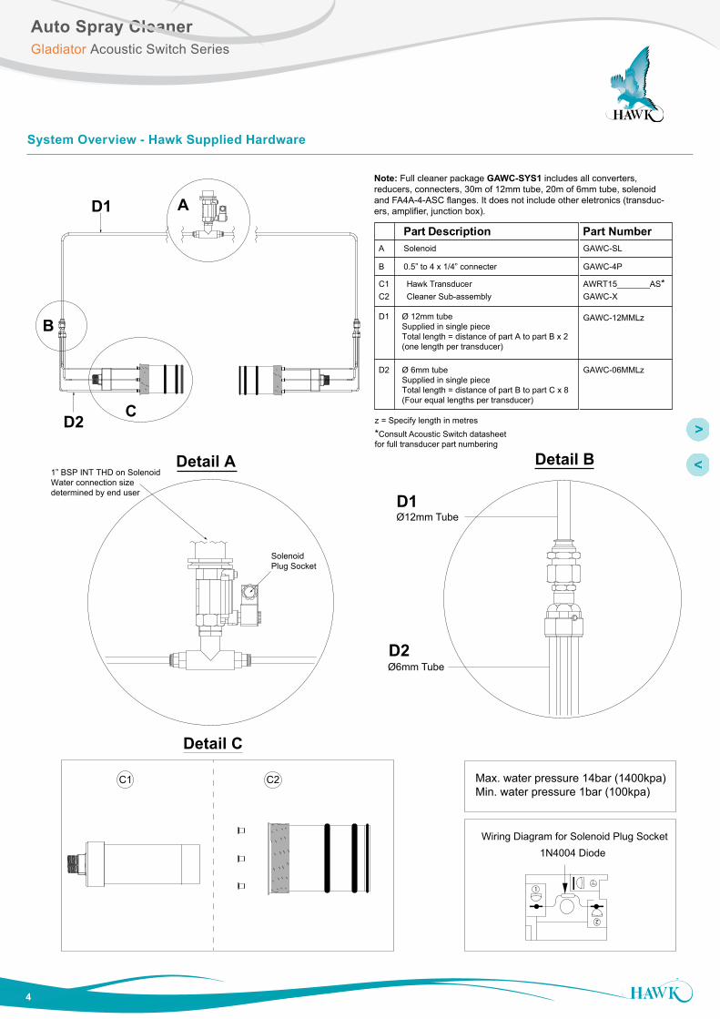
A
C
B
D1
D2
1” BSP INT THD on SolenoidWater connection size determined by end user
Detail A
Solenoid Plug Socket
C1 C2
Detail C
Ø12mm Tube
Ø6mm Tube
Detail B
D1
D2
Part Description Part Number
C1 Hawk TransducerC2 Cleaner Sub-assembly GAWC-X
AWRT15_______AS*
SolenoidA
0.5” to 4 x 1/4” connecterB
GAWC-SL
GAWC-4P
D1 Ø 12mm tubeSupplied in single pieceTotal length = distance of part A to part B x 2(one length per transducer)
D2 Ø 6mm tubeSupplied in single pieceTotal length = distance of part B to part C x 8(Four equal lengths per transducer)
GAWC-12MMLz
GAWC-06MMLz
z = Specify length in metres*Consult Acoustic Switch datasheetfor full transducer part numbering
1
2
1N4004 DiodeWiring Diagram for Solenoid Plug Socket
Max. water pressure 14bar (1400kpa)Min. water pressure 1bar (100kpa)
Note: Full cleaner package GAWC-SYS1 includes all converters, reducers, connecters, 30m of 12mm tube, 20m of 6mm tube, solenoid and FA4A-4-ASC flanges. It does not include other eletronics (transduc-ers, amplifier, junction box).
System Overview - Hawk Supplied Hardware
OverviewSultan Acoustic Wave Series
5
Auto Spray CleanerGladiator Acoustic Switch Series
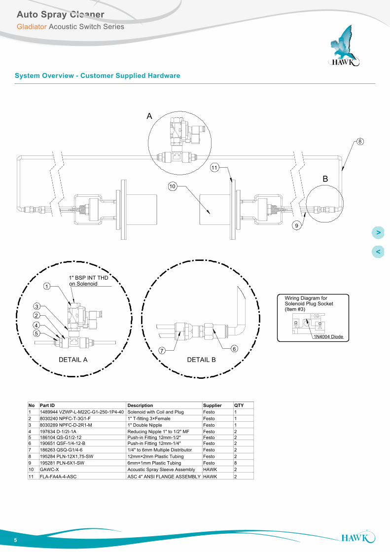
System Overview - Customer Supplied Hardware
A
B
8
9
10
Wiring Diagram for Solenoid Plug Socket(Item #3)
1N4004 Diode
11
DETAIL A
1
5
2
41 2
1" BSP INT THD on Solenoid
3
DETAIL B
67
No Part ID Description Supplier QTY1 1489944 VZWP-L-M22C-G1-250-1P4-40 Solenoid with Coil and Plug Festo 12 8030240 NPFC-T-3G1-F 1" T-fitting 3×Female Festo 13 8030289 NPFC-D-2R1-M 1" Double Nipple Festo 14 197634 D-1/2I-1A Reducing Nipple 1" to 1/2" MF Festo 25 186104 QS-G1/2-12 Push-in Fitting 12mm-1/2" Festo 26 190651 QSF-1/4-12-B Push-in Fitting 12mm-1/4" Festo 27 186263 QSQ-G1/4-6 1/4" to 6mm Multiple Distributor Festo 28 195284 PLN-12X1,75-SW 12mm×2mm Plastic Tubing Festo 29 195281 PLN-6X1-SW 6mm×1mm Plastic Tubing Festo 810 GAWC-X Acoustic Spray Sleeve Assembly HAWK 211 FLA-FA4A-4-ASC ASC 4" ANSI FLANGE ASSEMBLY HAWK 2
OverviewSultan Acoustic Wave Series
6
Auto Spray CleanerGladiator Acoustic Switch Series
ISOVIEW FOR REFERENCE ONLY
108mm
120.5mm
90mm
100mm
205mm
Thread to fitFA4A-4 Flange (included)
D
A BC*
STANDARD ANSI FLANGE DIMENSIONSFLANGE TYPE E (PCD) F (OD) G (ID) H (Hole)
mm in. mm in. mm in. mm in.FA4 ANSI class 150 190.5 7.5 229 9.0 100 4 19 0.75
SIZE
4”
No.Holes
8
Spray Sleeve
ISOVIEW FOR REFERENCE ONLY
100mm
H
E F
STANDARD ANSI FLANGE DIMENSIONSFLANGE TYPE E (PCD) F (OD) H (Hole)
mm in. mm in. mm in.FA4 ANSI class 150 190.5 7.5 229 9.0 19 0.75
SIZE
4”
No.Holes
8
Spray Sleeve
102mm
123mm250mm
Flange
Sensor face threadedto end of steel thread(10mm cavity)
3 x Rubber O-rings
Mounting Instruction
• Sleeve face should be flush with vessel wall interior
• Sensor face must be within slight cavity of sleeve approximately 10mm (end of internal thread).
• Solenoid and 4 way pipe converter should be mounted securely.
• Recommend 4 way pipe converter is kept close to mounting position on transducer - use 1” single pipe for as much distance as possible.
• Use a converter if required to interface with 1” HAWK recommended pipe connection.
Dimensions

OverviewSultan Acoustic Wave Series
7
Auto Spray CleanerGladiator Acoustic Switch Series
Relay 1 - Output RelayRelay 2 - FailSafe/Cleaner Relay
+ – A 1L+– NBRED
BLAC
K
BLUE
WHI
TEIs
SENSOR DC-In AC-In*4-20mA* COMMS
SLA
VE
IN
MA
STE
R O
UT
TEST
IN
RELAY 1
NC
CO
M
NO
RELAY 2
NC
CO
M
NO
1 2 3 4 5 6 7 8 9 10 11 12 13 14 15
16 17 18 19 20 21 22 23 24 25 26 27 28 29 30
+24V
1N4004 Diode
1 2
SOLENDOID
*Model dependant
GSA Amplifier
Wiring

OverviewSultan Acoustic Wave Series
8
Auto Spray CleanerGladiator Acoustic Switch Series
Hawk Measurement Systems(Head Office)15 - 17 Maurice Court Nunawading VIC 3131, AUSTRALIA
Phone: +61 3 9873 4750Fax: +61 3 9873 [email protected]
Hawk Measurement 96 Glenn StreetLawrence, MA 01843, USA
Phone: +1 888 HAWKLEVEL (1-888-429-5538)Phone: +1 978 304 3000Fax: +1 978 304 [email protected]
Represented by:
For more information and global representatives: www.hawkmeasure.comAdditional product warranty and application guarantees upon request. Technical data subject to change without notice.
DO
C-A
CO
US
TIC
-AS
C-D
AT v
1.4
021
5
Data sheet: Solenoid coil MD-2-24VDC-PA – #549903
Feature ValuesAssembly position AnySwitching position indicator NoDuty cycle 100%Characteristic coil data 24V DC: 6,8WPermissible voltage fluctuation +/- 10 %Protection class IP65Ambient temperature -20 ... 50 °CMax. tightening torque for fitting 0.5 NmProduct weight 110 gElectrical connection Per DIN EN 175301-803Mounting type With knurled nutMaterial information, solenoid coil Duroplast
CopperSteel
Material information, coil Copper
Water Pressure
• Maximum: 14bar (1400kpa) • Minimum: 1bar (100kpa)
Water Quality
• System requires good water quality. Install filter if required.
Water Usage
• Approximately 200ml per second per transducer (water pressure dependant)
Specifications
All
com
pany
or p
rodu
ct n
ames
are
regi
ster
ed tr
adem
arks
or t
rade
mar
ks o
f the
ir re
spec
tive
owne
rs.