gf1 - efes otomasyon - endüstriyel otomasyon - … · msystem micro panel gf1 device description...
TRANSCRIPT
MSystem
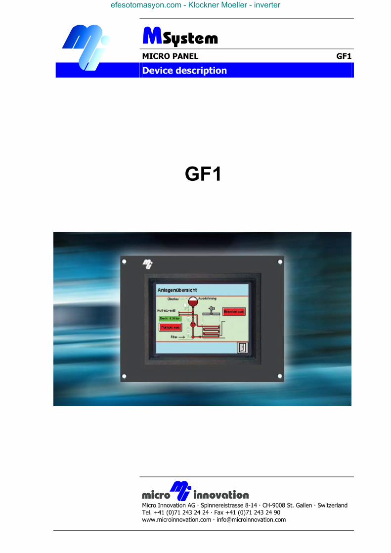
MICRO PANEL GF1
Device description
Micro Innovation AG Spinnereistrasse 8-14 CH-9008 St. Gallen Switzerland Tel. +41 (0)71 243 24 24 Fax +41 (0)71 243 24 90 www.microinnovation.com [email protected]
GF1
efesotomasyon.com - Klockner Moeller - inverter
Device description GF1 MICRO PANELCopyright
2
Technical subject to changeM000260-01.DOC
© by Micro Innovation
Copyright
Keep documentation for future use! This documentation is the intellectual property of Micro Innovation AG, which also has the exclusive copyright. Any modification of the content, dublication or reprinting of this documentation, as well as distribution to third parties can only be made with the express permission of Micro Innovation AG. Micro Innovation AG does not accept any liability for damages arising from the use of any incorrect or incomplete information contained in this documentation or any information missing therefrom. Micro Innovation AG reserves the right to male complete or partial modification to this document. All brand and product names are trademarks or registered trademarks of th owner concerned.
efesotomasyon.com - Klockner Moeller - inverter
MICRO PANEL Device description GF1 Proper use
Technical subject to change M000260-01.DOC © by Micro Innovation 3
Proper use Hardware, software, operatingsystems and drivers must only be used for the applications specified in this description and only in conjunction with the components recommended by Micro Innovation AG. Warning ! No warranty claims will be recognized for faults arising from the improper handling of any device. Devices and communication should not be used for the implementation of any safety functions relating to the protection of personnel and machinery. No liability is accepted for claims for damages arising from a failure or functional defect. All data specified in this document does not represent guaranteed specifications in the legal sense.
efesotomasyon.com - Klockner Moeller - inverter

Device description GF1 MICRO PANELContents
4
Technical subject to changeM000260-01.DOC
© by Micro Innovation
Contents 1 Explanation of Symbols ..................................................................................... 5 2 Introduction......................................................................................................... 6 3 Device version..................................................................................................... 7 4 Scope of delivery ................................................................................................ 8 5 Device Mounting ................................................................................................. 9
5.1 General mounting instructions................................................................................. 9 6 Dimensions, Views, Front Plate Cutout .......................................................... 10
6.1 10“-Version (GF1-10xxx) ....................................................................................... 10 7 Connection Assignment................................................................................... 11
7.1 System power supply for AC Version (100...240 VAC, GF1-xxxxA)...................... 11 7.2 System power supply for DC Version (24 VDC, GF1-xxxxD) ................................ 12 7.3 System Port (Function, Assignment) ..................................................................... 12
8 Memory Card Slot ............................................................................................. 13 9 The Touch Screen............................................................................................. 14
9.1 Basic function of the Touch Screen....................................................................... 14 9.2 Power up function test ........................................................................................... 14 9.3 Cleaning and care of the Touch Screen ................................................................ 14
10 Function and control LEDs .............................................................................. 15 11 Communication Modules and System Expansion (Slot 0, Slot 1) ................ 16 12 Installation Instructions ................................................................................... 17
12.1 Device installation .............................................................................................. 17 12.2 Mounting to IP65 ................................................................................................ 17 12.3 Preparation of the connection cables (EMC)...................................................... 18 12.4 Preparing the shield connections ....................................................................... 19
13 EU Conformity................................................................................................... 20 14 Technical Data................................................................................................... 21 15 Revision History................................................................................................ 23
efesotomasyon.com - Klockner Moeller - inverter
MICRO PANEL Device description GF1 Explanation of Symbols
Technical subject to change M000260-01.DOC © by Micro Innovation 5
1 EXPLANATION OF SYMBOLS
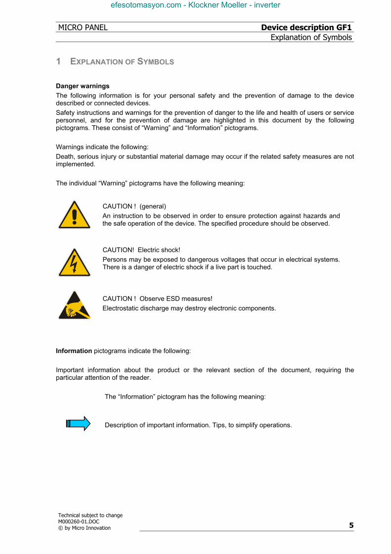
Danger warnings The following information is for your personal safety and the prevention of damage to the device described or connected devices. Safety instructions and warnings for the prevention of danger to the life and health of users or service personnel, and for the prevention of damage are highlighted in this document by the following pictograms. These consist of “Warning” and “Information” pictograms. Warnings indicate the following: Death, serious injury or substantial material damage may occur if the related safety measures are not implemented. The individual “Warning” pictograms have the following meaning:
CAUTION ! (general) An instruction to be observed in order to ensure protection against hazards and the safe operation of the device. The specified procedure should be observed.
CAUTION! Electric shock! Persons may be exposed to dangerous voltages that occur in electrical systems. There is a danger of electric shock if a live part is touched.
CAUTION ! Observe ESD measures! Electrostatic discharge may destroy electronic components.
Information pictograms indicate the following: Important information about the product or the relevant section of the document, requiring the particular attention of the reader.
The “Information” pictogram has the following meaning:
Description of important information. Tips, to simplify operations.
efesotomasyon.com - Klockner Moeller - inverter
Device description GF1 MICRO PANELIntroduction
6
Technical subject to changeM000260-01.DOC
© by Micro Innovation
2 INTRODUCTION The Micro Panel GF-1 a visualisation unit that is provided with touch zone functions for medium to high complexity automation systems, meeting all the requirements placed on a modern visualisation unit. The Micro Panel GF-1 must be loaded before use with the appropriate project data. This is stored in the external plug-in memory card (PC card). The memory card in the GF-1 can be loaded with project data via a download or directly on the PC (PC card slot). The project data is created using the design software for the GF-1 device series (GALILEO). The Micro Panel GF-1 provides two slots for communication modules or system expansions (→ Section 11). The communication card handles the connection to the automation system. They are described in separate documentation. This device description is a reference for technical data, information on installing, terminals, commissioning and operating all the versions of the Micro Panel GF-1. The illustrations in this documentation refer to the 10“-Version (→ Section 2), unless otherwise noted. Lettering and function of the terminals and indicators are the same for all device versions.
efesotomasyon.com - Klockner Moeller - inverter
MICRO PANEL Device description GF1 Device version
Technical subject to change M000260-01.DOC © by Micro Innovation 7
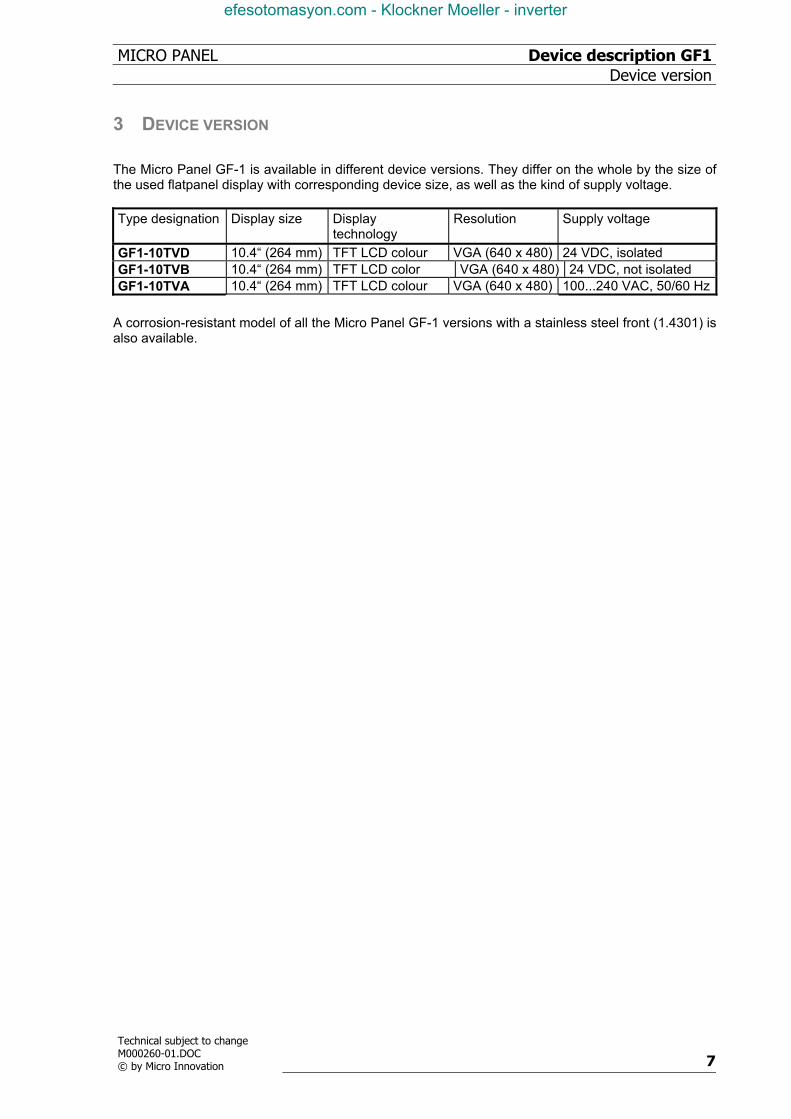
3 DEVICE VERSION The Micro Panel GF-1 is available in different device versions. They differ on the whole by the size of the used flatpanel display with corresponding device size, as well as the kind of supply voltage. Type designation Display size Display
technology Resolution Supply voltage
GF1-10TVD 10.4“ (264 mm) TFT LCD colour VGA (640 x 480) 24 VDC, isolated GF1-10TVB 10.4“ (264 mm) TFT LCD color VGA (640 x 480) 24 VDC, not isolated GF1-10TVA 10.4“ (264 mm) TFT LCD colour VGA (640 x 480) 100...240 VAC, 50/60 Hz
A corrosion-resistant model of all the Micro Panel GF-1 versions with a stainless steel front (1.4301) is also available.
efesotomasyon.com - Klockner Moeller - inverter
Device description GF1 MICRO PANELScope of delivery
8
Technical subject to changeM000260-01.DOC
© by Micro Innovation
4 SCOPE OF DELIVERY
The following components are supplied with the basic equipment : Micro Panel GF-1 including PC-Card retaining device and a blind plate with knurled screws for System Slot 1 • Fixing screws for device installation (4 pcs.) • Seal for device installation • Power supply plug - DC Version (GF1-xxxxD) : plug-in screw terminal (3 pole)(Poenix, Type : MSTB 2.5/3-ST-5.08) - AC Version (GF1-xxxxA) : Standard appliance plug • Device description
efesotomasyon.com - Klockner Moeller - inverter
MICRO PANEL Device description GF1 Device Mounting
Technical subject to change M000260-01.DOC © by Micro Innovation 9
5 DEVICE MOUNTING
5.1 GENERAL MOUNTING INSTRUCTIONS
The Micro Panel GF1 series comes in different mounting versions. The front panel version with 4 fixing holes (xx0) is specially designed for mounting in an enclosure or cabinet where there is no possibility of access from the rear. It is fixed from the front with four countersunk screws through the front plate (→ Section 5). The front versions with threaded bolts at the back require access from the rear. Washers and nuts are used to mount the device from the rear. All mounting versions ensure a sealed mounting to IP65. The relevant mounting instructions must be observed (→ Section 5.2). Ensure that the mounting allows access to connections, status LEDs, operating elements, such as the Download button and the memory card (PC card). Ensure sufficient space for outgoing cables (connector housings and bending radii of cables). The Micro Panel GF1 can be run at a maximum ambient temperature of 50°C (→ Section 21). The ambient temperature refers to the air temperature in the vicinity of the lower cooling slots, with vertical mounting, unobstructed air convection and a maximum operating altitude of 2000m above sea level. When mounting in an enclosure or cabinet, the ambient temperature is likewise the air temperature inside the enclosure concerned. In this case it is assumed that the air temperature at the front of the device is not higher than the temperature in the enclosure or cabinet, and there is no additional heat caused by radiation or conduction that has an effect on the device. The cooling slots must always be free in order to ensure the proper cooling of the system. Ensure a wall clearance of at least 3 cm on all sides of the housing, so that proper air circulation is not impaired. Avoid exposure to direct sunlight on the flat screen, even when it is switched off. The sunlight (UV component) and the resulting heat may damage the display.
The cooling slots must always be free in order to ensure the proper cooling of the system. Avoid the exposure of the flat screen to direct sunlight. Ensure that operating elements (Download button, memory card) and connections are still accessible when the device is mounted.
efesotomasyon.com - Klockner Moeller - inverter
Device description GF1 MICRO PANELDimensions, Views, Front Plate Cutout
10
Technical subject to changeM000260-01.DOC
© by Micro Innovation
6 DIMENSIONS, VIEWS, FRONT PLATE CUTOUT
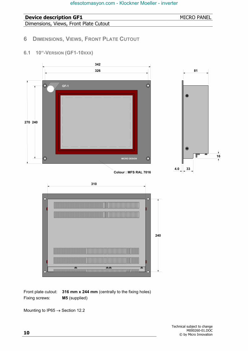
6.1 10“-VERSION (GF1-10XXX)
GF-1
MICRO DESIGN
4.0 33
16
81
342
326
240270
240
310
Colour : MFS RAL 7016
Front plate cutout: 316 mm x 244 mm (centrally to the fixing holes) Fixing screws: M5 (supplied) Mounting to IP65 → Section 12.2
efesotomasyon.com - Klockner Moeller - inverter
MICRO PANEL Device description GF1 Connection Assignment
Technical subject to change M000260-01.DOC © by Micro Innovation 11
7 CONNECTION ASSIGNMENT
7.1 SYSTEM POWER SUPPLY FOR AC VERSION (100...240 VAC, GF1-XXXXA)
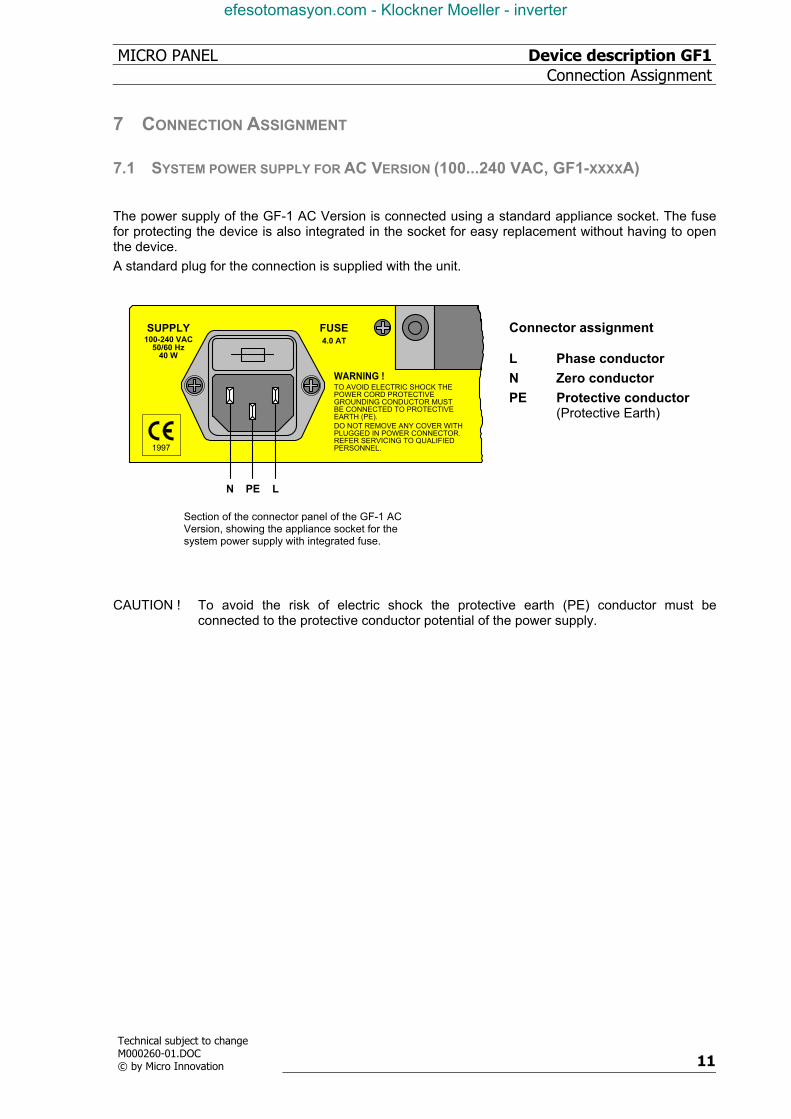
The power supply of the GF-1 AC Version is connected using a standard appliance socket. The fuse for protecting the device is also integrated in the socket for easy replacement without having to open the device. A standard plug for the connection is supplied with the unit.
4.0 ATFUSE
1997
SUPPLY100-240 VAC
50/60 Hz40 W
TO AVOID ELECTRIC SHOCK THEPOWER CORD PROTECTIVEGROUNDING CONDUCTOR MUSTBE CONNECTED TO PROTECTIVEEARTH (PE).DO NOT REMOVE ANY COVER WITHPLUGGED IN POWER CONNECTOR.REFER SERVICING TO QUALIFIEDPERSONNEL.
WARNING !
PE LN
Section of the connector panel of the GF-1 AC Version, showing the appliance socket for the system power supply with integrated fuse.
Connector assignment L Phase conductorN Zero conductorPE Protective conductor
(Protective Earth)
CAUTION ! To avoid the risk of electric shock the protective earth (PE) conductor must be
connected to the protective conductor potential of the power supply.
efesotomasyon.com - Klockner Moeller - inverter
Device description GF1 MICRO PANELConnection Assignment
12
Technical subject to changeM000260-01.DOC
© by Micro Innovation
7.2 SYSTEM POWER SUPPLY FOR DC VERSION (24 VDC, GF1-XXXXD)
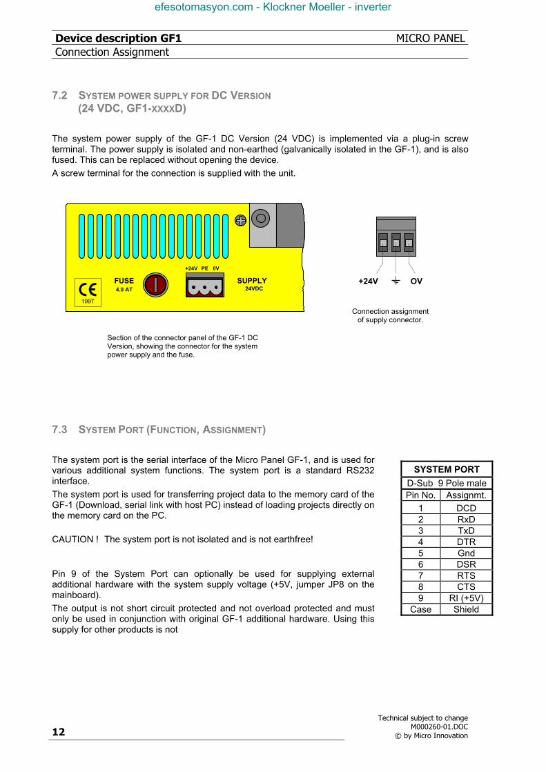
The system power supply of the GF-1 DC Version (24 VDC) is implemented via a plug-in screw terminal. The power supply is isolated and non-earthed (galvanically isolated in the GF-1), and is also fused. This can be replaced without opening the device. A screw terminal for the connection is supplied with the unit.
SUPPLY4.0 ATFUSE
+24V PE 0V
24VDC
1997
Section of the connector panel of the GF-1 DC Version, showing the connector for the system power supply and the fuse.
+24V OV
Connection assignment of supply connector.
7.3 SYSTEM PORT (FUNCTION, ASSIGNMENT) The system port is the serial interface of the Micro Panel GF-1, and is used for various additional system functions. The system port is a standard RS232 interface. The system port is used for transferring project data to the memory card of the GF-1 (Download, serial link with host PC) instead of loading projects directly on the memory card on the PC. CAUTION ! The system port is not isolated and is not earthfree! Pin 9 of the System Port can optionally be used for supplying external additional hardware with the system supply voltage (+5V, jumper JP8 on the mainboard). The output is not short circuit protected and not overload protected and must only be used in conjunction with original GF-1 additional hardware. Using this supply for other products is not
SYSTEM PORT D-Sub 9 Pole malePin No. Assignmt.
1 DCD 2 RxD 3 TxD 4 DTR 5 Gnd 6 DSR 7 RTS 8 CTS 9 RI (+5V)
Case Shield
efesotomasyon.com - Klockner Moeller - inverter
MICRO PANEL Device description GF1 Memory Card Slot
Technical subject to change M000260-01.DOC © by Micro Innovation 13
8 MEMORY CARD SLOT
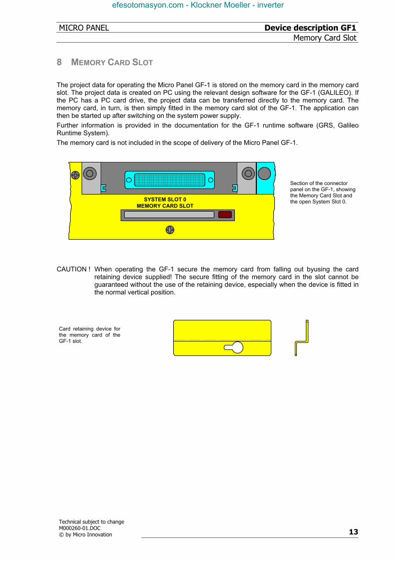
The project data for operating the Micro Panel GF-1 is stored on the memory card in the memory card slot. The project data is created on PC using the relevant design software for the GF-1 (GALILEO). If the PC has a PC card drive, the project data can be transferred directly to the memory card. The memory card, in turn, is then simply fitted in the memory card slot of the GF-1. The application can then be started up after switching on the system power supply. Further information is provided in the documentation for the GF-1 runtime software (GRS, Galileo Runtime System). The memory card is not included in the scope of delivery of the Micro Panel GF-1.
MEMORY CARD SLOTSYSTEM SLOT 0
Section of the connector panel on the GF-1, showing the Memory Card Slot and the open System Slot 0.
CAUTION ! When operating the GF-1 secure the memory card from falling out byusing the card
retaining device supplied! The secure fitting of the memory card in the slot cannot be guaranteed without the use of the retaining device, especially when the device is fitted in the normal vertical position.
Card retaining device for the memory card of the GF-1 slot.
efesotomasyon.com - Klockner Moeller - inverter

Device description GF1 MICRO PANELThe Touch Screen
14
Technical subject to changeM000260-01.DOC
© by Micro Innovation
9 THE TOUCH SCREEN
9.1 BASIC FUNCTION OF THE TOUCH SCREEN The function of Touch Screen is based on the active light matrix principle in the infrared range. The optical elements of the light matrix are located behind the IR transparent plastic frame in the front of the device. They are located in such a way that their radiation extends slightly out of the front plate. Each emitter is assigned a receiver that is located on the other side. In this way a total of 70 IR channels are arranged closely together. A touch on the screen is detected by the simultaneous interruption of one or several channels in the X or Y axis. Repeated touches and touches that cover an area greater than 20 mm x 20 mm are not evaluated by the touch controller. Continuously interrupted channels caused by severe contamination and dirt, or by the failure an optical element, are detected by the touch controller and are no longer included in the evaluation.
9.2 POWER UP FUNCTION TEST The GF-1 runs through a function test of the Touch Screen with every start-up. All the IR channels are evaluated and their signal levels compared with those of the initial values. The initial values are determined before the device is delivered and stored in a retentive memory. If one or several channel signals is below a minimum relative to the initial level, this will be indicated on the screen with an error message and the DEF/DIRTY LED will be lit (→ Section 10). A reduced signal level of this kind is normally due to severe contamination of the IR transparent plastic frame which consequently has to be cleaned (→ Section 9.3). The Touch Screen, however, remains fully functional. Only an increase in the contamination of the screen will lead to the continuous interruptions of one or several IR channels. IR channels that are continuously interrupted will be detected by the touch controller and no longer included in the evaluation. In extreme cases, this may mean that individual zones cannot be activated by touch. CAUTION ! Do not touch the screen whilst the system is being started up, and wait till your
application has started.The Touch Screen carries out a function test during the start up in which the signal levels of the IR channels are measured.
9.3 CLEANING AND CARE OF THE TOUCH SCREEN
For operation ensure that the signal levels of the channels are not so severely reduced or interrupted due to excessive contamination through dirt (→ Section 9.1). Clean the inside of the plastic frame of the device regularly with a damp soft cloth. Ensure that the surface is not scratched or scoured, especially when removing hard deposits and abrasive dusts. Do not expose the front of the device to solvents which may corrode and loosen the plastic frame (frame material: polymethylmethacrylate, PMMA).
efesotomasyon.com - Klockner Moeller - inverter
MICRO PANEL Device description GF1 Function and control LEDs
Technical subject to change M000260-01.DOC © by Micro Innovation 15
10 FUNCTION AND CONTROL LEDS
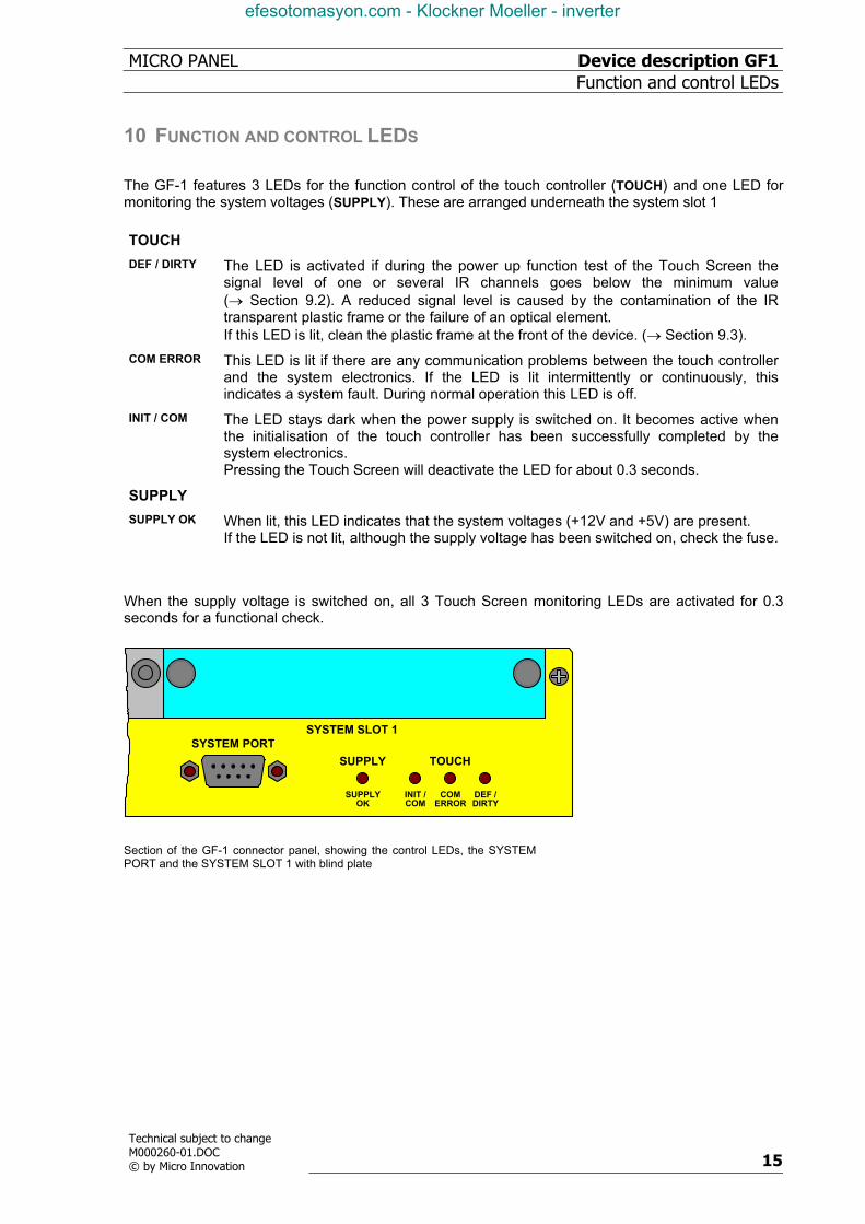
The GF-1 features 3 LEDs for the function control of the touch controller (TOUCH) and one LED for monitoring the system voltages (SUPPLY). These are arranged underneath the system slot 1
TOUCH DEF / DIRTY The LED is activated if during the power up function test of the Touch Screen the
signal level of one or several IR channels goes below the minimum value (→ Section 9.2). A reduced signal level is caused by the contamination of the IR transparent plastic frame or the failure of an optical element. If this LED is lit, clean the plastic frame at the front of the device. (→ Section 9.3).
COM ERROR This LED is lit if there are any communication problems between the touch controller and the system electronics. If the LED is lit intermittently or continuously, this indicates a system fault. During normal operation this LED is off.
INIT / COM The LED stays dark when the power supply is switched on. It becomes active when the initialisation of the touch controller has been successfully completed by the system electronics. Pressing the Touch Screen will deactivate the LED for about 0.3 seconds.
SUPPLY SUPPLY OK When lit, this LED indicates that the system voltages (+12V and +5V) are present.
If the LED is not lit, although the supply voltage has been switched on, check the fuse. When the supply voltage is switched on, all 3 Touch Screen monitoring LEDs are activated for 0.3 seconds for a functional check.
SUPPLY
TOUCHSUPPLY
OKINIT /COM
COMERROR
DEF /DIRTY
SYSTEM PORTSYSTEM SLOT 1
Section of the GF-1 connector panel, showing the control LEDs, the SYSTEM PORT and the SYSTEM SLOT 1 with blind plate
efesotomasyon.com - Klockner Moeller - inverter

Device description GF1 MICRO PANELCommunication Modules and System Expansion (Slot 0, Slot
16
Technical subject to changeM000260-01.DOC
© by Micro Innovation
11 COMMUNICATION MODULES AND SYSTEM EXPANSION (SLOT 0, SLOT 1) The Micro Panel GF-1 provides two slots for communication modules and system expansions. The different communication modules available allow the Touch Screen to be connected to the automation system (e.g. PLC) or the field bus system required. The use of two communication modules allows two communication systems to be operative at the same time. Information on communication modules and protocols that are currently available can be obtained from your local Micro Panel dealer or from Micro Design Systems AG Technical Support. CAUTION! Do not handle the plug-in cards (modules) without observing the relevant safety
measures concerning electrostatic discharge (ESD). Do not fit the modules with the power supply switched on. Only operate the modules once they have been screwed into position. Do not operate non-Micro Design components in the slots. Only the original
hardware of Micro Design Systems AG must be used
efesotomasyon.com - Klockner Moeller - inverter
MICRO PANEL Device description GF1 Installation Instructions
Technical subject to change M000260-01.DOC © by Micro Innovation 17
12 INSTALLATION INSTRUCTIONS
12.1 DEVICE INSTALLATION
When installing the Micro Panel GF-1, a minimum distance of 10 cm must be ensured between the device and any other components, so that the cooling of the system is not impaired. The cooling slits must not be covered by cables or other objects. The specified operating temperature (→ Section 5) is based on a vertical mounting with unhindered air convection and a location of no more than 2000 m above sea level. Avoid the exposure of the flat screen to direct sunlight. The radiation from the sun (UV component) reduces the lifespan of the liquid crystal.
12.2 MOUNTING TO IP65
A mounting kit is available for installations complying with degree of protection IP65. This consists of a conter frame that is mounted on the rear of the device so that the required pressure on the seal is ensured even when fitting to a thin panel. The seal is supplied with the delivery. The conter frame must be ordered separately. Order designation : - 10“-Version : Conter frame for GF1-10xxx
MDS Ord. No. : 65 20 963100
efesotomasyon.com - Klockner Moeller - inverter
Device description GF1 MICRO PANELInstallation Instructions
18
Technical subject to changeM000260-01.DOC
© by Micro Innovation
12.3 PREPARATION OF THE CONNECTION CABLES (EMC) The preparation of the data and signal cables is an important factor in the electromagnetic compatibility (EMC) of the Micro Panel GF-1, both in terms of interference immunity and emission. The EMC values stated in the technical data can only be guaranteed if the cables are prepared according to the following specifications. All data cables on the GF-1 (System Port) and on the modules in the slots (Slot 0 and Slot 1) must be shielded unless unshielded wiring is expressly stipulated. The power supply cable is not shielded. The cable shield must be made from copper braid. Only use a metal or metallised connector casing. Connect the cable shield directly to the low-impedance connector casing on the GF-1. This ensures that the cable screen is properly connected to the housing of the Micro Panel GF-1 via the screws and the protective metal shroud of the plug connector (low-impedance). Cables must also be shielded if they are disconnected at the other end or are only connected during commissioning or servicing. Refer to the relevant operating instructions of the PLC manufacturer for the correct connection procedure for the cable shield at the other end. Unless otherwise stated, connect the cable shield to the metal or metallised connector casing on the PLC. Avoid leaving the shield open. The data connections to be shielded involve the high-speed transfer of digital signals between two active systems. The cable shield only functions against asymmetrical interference transients if the shield is connected to the device earths (usually metallic device casing) at both ends. Provide a potential equalisation cable with a suitable cross-section between potentials (control cabinets) if the Micro Panel GF-1 and the communication partner are installed in different control cabinets or at different PE potentials (zero conductor potentials), and if the cable shield is directly or indirectly connected at both ends to the protective earth conductor. This will prevent the occurrence of excessive compensation currents on the shield and shield connections, as may occur in the event of a possible shorting of a device on the protective earth system. These kinds of compensation currents of normally 50 Hz even occur in normal operation and do not represent a problem for data transmission. However, they may cause the destruction of the shield contacts, particularly in the event of short-circuits in the environment.
efesotomasyon.com - Klockner Moeller - inverter
MICRO PANEL Device description GF1 Installation Instructions
Technical subject to change M000260-01.DOC © by Micro Innovation 19
12.4 PREPARING THE SHIELD CONNECTIONS
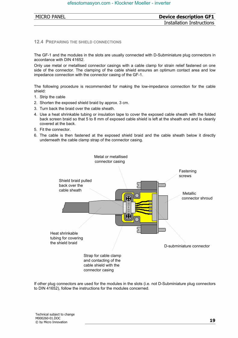
The GF-1 and the modules in the slots are usually connected with D-Subminiature plug connectors in accordance with DIN 41652. Only use metal or metallised connector casings with a cable clamp for strain relief fastened on one side of the connector. The clamping of the cable shield ensures an optimum contact area and low impedance connection with the connector casing of the GF-1. The following procedure is recommended for making the low-impedance connection for the cable shield: 1. Strip the cable 2. Shorten the exposed shield braid by approx. 3 cm. 3. Turn back the braid over the cable sheath. 4. Use a heat shrinkable tubing or insulation tape to cover the exposed cable sheath with the folded
back screen braid so that 5 to 8 mm of exposed cable shield is left at the sheath end and is cleanly covered at the back.
5. Fit the connector. 6. The cable is then fastened at the exposed shield braid and the cable sheath below it directly
underneath the cable clamp strap of the connector casing.
Metal or metallised
D-subminiature connector
Metallicconnector shroud
Fasteningscrews
connector casing
Heat shrinkable tubing for covering the shield braid
Shield braid pulledback over the cable sheath
Strap for cable clampand contacting of the cable shield with theconnector casing
If other plug connectors are used for the modules in the slots (i.e. not D-Subminiature plug connectors to DIN 41652), follow the instructions for the modules concerned.
efesotomasyon.com - Klockner Moeller - inverter
Device description GF1 MICRO PANELEU Conformity
20
Technical subject to changeM000260-01.DOC
© by Micro Innovation
13 EU CONFORMITY The Micro Panel GF-1 meets the requirements specified by the Directives of the EU Council for harmonizing the regulations of EU member states relating to electromagnetic compatibility (89/336/EEC) and electrical safety (Low-Voltage Directive 73/23/EEC). The following basic standards were used to assess the electromagnetic compatibility of the Micro Panel GF-1 : EN 50081-2 (Emission) EN 50082-2 (Immunity) The following standard has been used as a basis for assessing the Micro Panel GF-1 with respect to its electrical safety : EN 60950 Manufacturer : Micro Innovation AG Manufacturer address : Spinnereistrasse 8-14 9008 St. Gallen Switzerland
1997
efesotomasyon.com - Klockner Moeller - inverter
MICRO PANEL Device description GF1 Technical Data
Technical subject to change M000260-01.DOC © by Micro Innovation 21
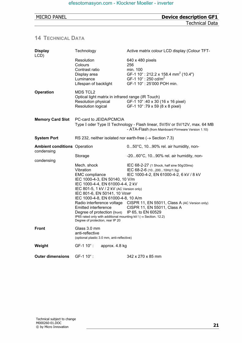
14 TECHNICAL DATA Display Technology Active matrix colour LCD display (Colour TFT-LCD) Resolution 640 x 480 pixels Colours 256 Contrast ratio min. 100 Display area GF-1 10“ : 212.2 x 158.4 mm2 (10.4") Luminance GF-1 10“ : 250 cd/m2 Lifespan of backlight GF-1 10“ : 25’000 POH min.
Operation MDS TCL2 Optical light matrix in infrared range (IR Touch) Resolution physical GF-1 10“ :40 x 30 (16 x 16 pixel) Resolution logical GF-1 10“ :79 x 59 (8 x 8 pixel)
Memory Card Slot PC-card to JEIDA/PCMCIA Type I oder Type II Technology - Flash linear, 5V/5V or 5V/12V, max. 64 MB - ATA-Flash (from Mainboard Firmware Version 1.10)
System Port RS 232, neither isolated nor earth-free (→ Section 7.3)
Ambient conditions Operation 0...50°C, 10...90% rel. air humidity, non-condensing Storage -20...60°C, 10...90% rel. air humidity, non-condensing Mech. shock IEC 68-2-27 (1 Shock, half sine 50g/20ms) Vibration IEC 68-2-6 (10...200...10Hz/1.5g) EMC compliance IEC 1000-4-2, EN 61000-4-2, 6 kV / 8 kV IEC 1000-4-3, EN 50140, 10 V/m IEC 1000-4-4, EN 61000-4-4, 2 kV IEC 801-5, 1 kV / 2 kV (AC Version only) IEC 801-6, EN 50141, 10 VEMF IEC 1000-4-8, EN 61000-4-8, 10 A/m Radio interference voltage CISPR 11, EN 55011, Class A (AC Version only) Emitted interference CISPR 11, EN 55011, Class A Degree of protection (front) IP 65, to EN 60529 IP65 rated only with additional mounting kit ! (→ Section. 12.2) Degree of protection, rear IP 20
Front Glass 3.0 mm anti-reflective (optional plastic 3.0 mm, anti-reflective)
Weight GF-1 10“ : approx. 4.8 kg Outer dimensions GF-1 10“ : 342 x 270 x 85 mm
efesotomasyon.com - Klockner Moeller - inverter
Device description GF1 MICRO PANELTechnical Data
22
Technical subject to changeM000260-01.DOC
© by Micro Innovation
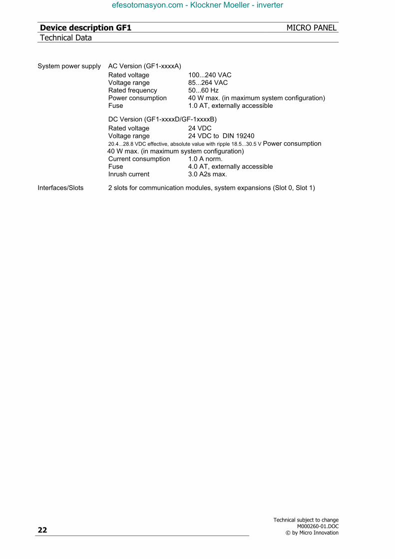
System power supply AC Version (GF1-xxxxA) Rated voltage 100...240 VAC Voltage range 85...264 VAC Rated frequency 50...60 Hz Power consumption 40 W max. (in maximum system configuration) Fuse 1.0 AT, externally accessible
DC Version (GF1-xxxxD/GF-1xxxxB) Rated voltage 24 VDC Voltage range 24 VDC to DIN 19240 20.4...28.8 VDC effective, absolute value with ripple 18.5...30.5 V Power consumption 40 W max. (in maximum system configuration) Current consumption 1.0 A norm. Fuse 4.0 AT, externally accessible Inrush current 3.0 A2s max.
Interfaces/Slots 2 slots for communication modules, system expansions (Slot 0, Slot 1)
efesotomasyon.com - Klockner Moeller - inverter
MICRO PANEL Device description GF1 Revision History
Technical subject to change M000260-01.DOC © by Micro Innovation 23
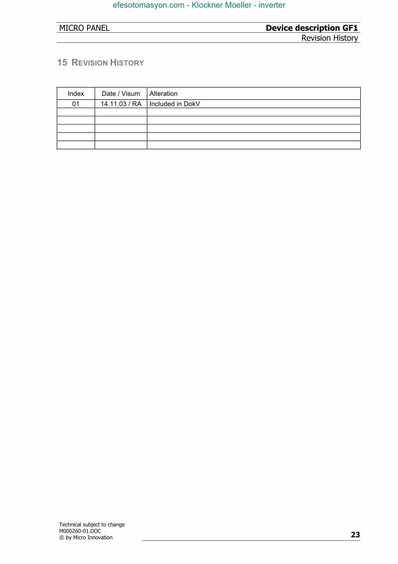
15 REVISION HISTORY
Index Date / Visum Alteration 01 14.11.03 / RA Included in DokV
efesotomasyon.com - Klockner Moeller - inverter
Device description GF1 MICRO PANELRevision History
24
Technical subject to changeM000260-01.DOC
© by Micro Innovation
Micro Innovation AG Spinnereistr 8-14 CH-9008 St. Gallen Switzerland Tel : ++41- 71 243 24 24 Fax : ++41- 71 243 24 90 email : [email protected] homepage : http://www.microinnovation.com
efesotomasyon.com - Klockner Moeller - inverter