getting started with 3d in microstation connect edition
TRANSCRIPT

Bentley MicroStation Workshop
2017 FLUG Spring Training Event
441 - Getting Started with 3D in MicroStation Connect Edition
Bentley Systems, Incorporated 685 Stockton Drive Exton, PA 19341 www.bentley.com

Practice Workbook
This workbook is designed for use in Live instructor-led training and for OnDemand selfstudy. The explanations and demonstrations are provided by the instructor in the classroom, or in the OnDemand eLectures of this course available on the Bentley LEARN Server (learn.bentley.com).
This practice workbook is formatted for on-screen viewing using a PDF reader. It is also available as a PDF document in the dataset for this course.
DO NOT DISTRIBUTE - Printing for student use is permitted
Getting Started with 3D in MicroStation CONNECT Edition
TRNC02001-1/0001

Copyright © 2015 Bentley Systems, Incorporated 2DO NOT DISTRIBUTE - Printing for student use is permitted
Description and Objectives
Learning 3 Dimensional (3D) drawing with MicroStation CONNECT Edition is an extension of your knowledge of 2 Dimensional (2D) drawing. If you can draw in 2D, then all that is needed is to learn how to manipulate the AccuDraw compass in 3D space.
Course Description
This workbook contains exercises that will provide the basic skills required to:
Skills Taught
Begin a transition from 2D drafting to 3D Designing
Provide an understanding of the 3D Workspace
Show how to use 3D standard, rotated, and Saved views
Isolate parts of a design using Clip Volumes
Create Auxiliary Coordinate Systems for any 3D plane
Design using AccuDraw in 3D space
Create and place 3D Cells
Transitioning from 2D Drafting to 3D Designing
In this section, we will open the MicroStation design file:
01-Transitioning from 2D to 3D.dgn
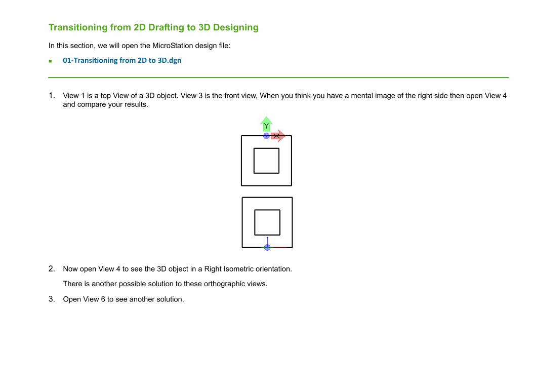
1. View 1 is a top View of a 3D object. View 3 is the front view, When you think you have a mental image of the right side then open View 4 and compare your results.
2. Now open View 4 to see the 3D object in a Right Isometric orientation.
There is another possible solution to these orthographic views.
3. Open View 6 to see another solution.

Copyright © 2015 Bentley Systems, Incorporated 4DO NOT DISTRIBUTE - Printing for student use is permitted
4. Let’s take a look at a 2D shape created in a 3D DGN file by opening 02-2D Shapes in 3D Space.dgn.
This 3D design has only a 2D block created in the Top view. The height of this 2D Shape or closed profile has no Z value.The front, View3 and right side, View 4 appear as a line with no height in Z axis.

Copyright © 2015 Bentley Systems, Incorporated 5DO NOT DISTRIBUTE - Printing for student use is permitted
5. If we add a Z value the 2D shape is now a 3D object.Open 03-2D Shape extruded.dgn. The technique for adding the height will be covered in another course.
Copyright © 2015 Bentley Systems, Incorporated 6DO NOT DISTRIBUTE - Printing for student use is permitted
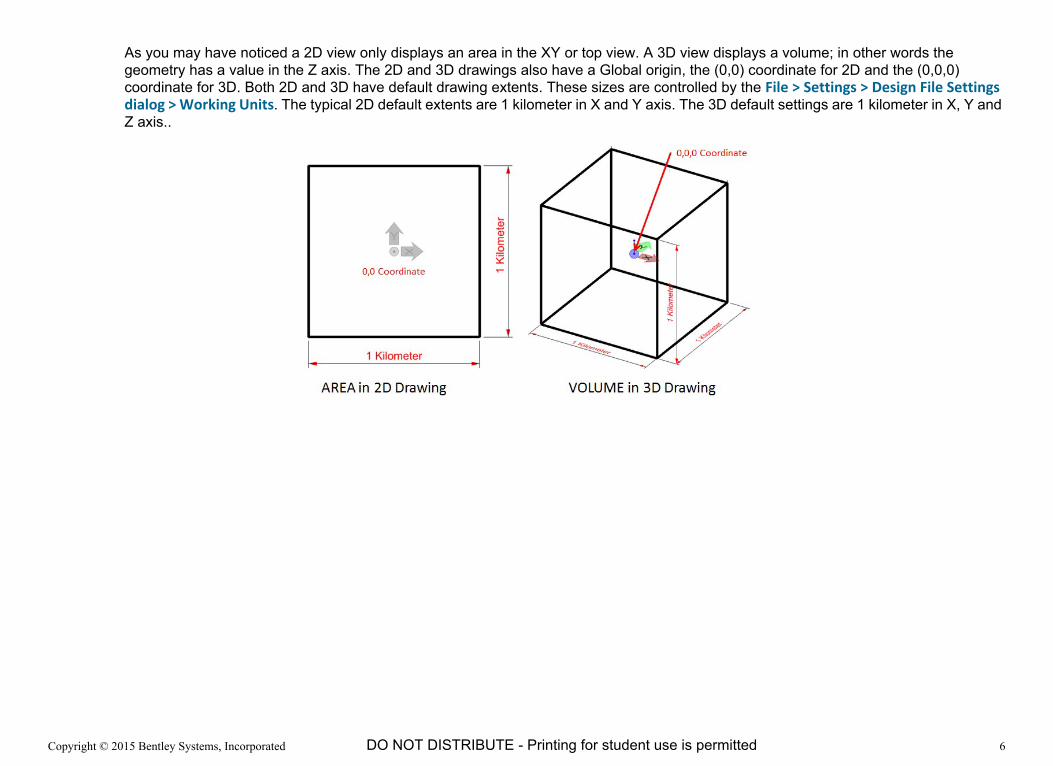
As you may have noticed a 2D view only displays an area in the XY or top view. A 3D view displays a volume; in other words the geometry has a value in the Z axis. The 2D and 3D drawings also have a Global origin, the (0,0) coordinate for 2D and the (0,0,0) coordinate for 3D. Both 2D and 3D have default drawing extents. These sizes are controlled by the File > Settings > Design File Settings dialog > Working Units. The typical 2D default extents are 1 kilometer in X and Y axis. The 3D default settings are 1 kilometer in X, Y and Z axis..
Copyright © 2015 Bentley Systems, Incorporated 7DO NOT DISTRIBUTE - Printing for student use is permitted
Viewing 3D Geometry
When working with 3D geometry it is very important to be able to rotate the geometry around any axis. It is also necessary to change to any standard orthographic view.
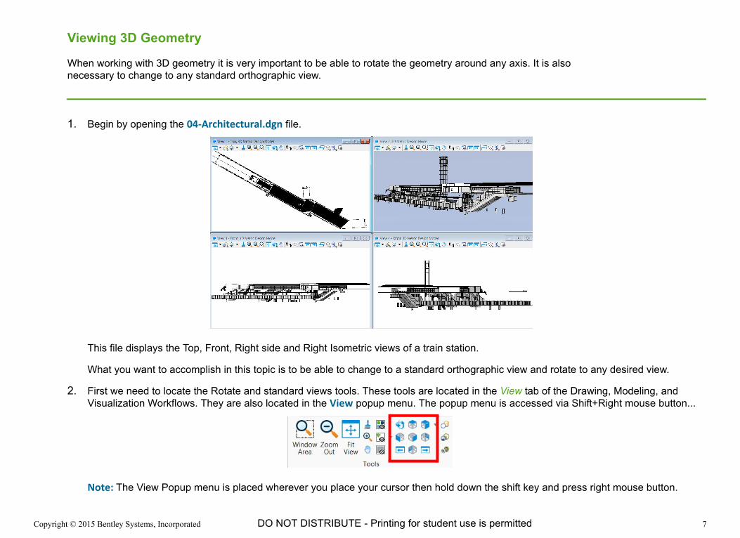
1. Begin by opening the 04-Architectural.dgn file.
This file displays the Top, Front, Right side and Right Isometric views of a train station.
What you want to accomplish in this topic is to be able to change to a standard orthographic view and rotate to any desired view.
2. First we need to locate the Rotate and standard views tools. These tools are located in the View tab of the Drawing, Modeling, and Visualization Workflows. They are also located in the View popup menu. The popup menu is accessed via Shift+Right mouse button...
Note: The View Popup menu is placed wherever you place your cursor then hold down the shift key and press right mouse button.

Copyright © 2015 Bentley Systems, Incorporated 8DO NOT DISTRIBUTE - Printing for student use is permitted
3. Let’s work with one view. Close Views 1,3 and 4.and Fit View in View 2.
4. Using the Right Isometric tool, set View 2 to Right Isometric.
5. Use the Standard View tools to change View 2 to Top, Front and Right Isometric Views.With only one view open you have more room for designing.
6. To create a custom view you will use the Rotate tool.
7. After you select the Rotate tool you will notice the Tool Settings Method is set to Dynamic, and you will see a plus sign in View 2. This plus sign is the center of rotation. Hold down the left mouse button and move your cursor left, right, up or down. The geometry in the view will rotate. Remember the geometry is not rotating, just you the observer. You are looking at the geometry from different angles.

Copyright © 2015 Bentley Systems, Incorporated 9DO NOT DISTRIBUTE - Printing for student use is permitted
8. Move the plus sign by moving your cursor over the plus sign, then pressing the left mouse button and dragging the plus sign to any point on the geometry. This will now become the new center of rotation. You can also move your scroll wheel forward and backward to zoom into the geometry.
9. To pan the view hold down the mouse wheel as a button and drag by moving your cursor. Try setting the view as pictured below.
10. All of the rotation so far used the Cube rotation with the option Preserve World Up enabled in the Rotate tool settings. Preserve World Up means the Z axis is always pointing straight up from Active Auxiliary Plane. Auxiliary Coordinate Systems will be in a later topic.
Copyright © 2015 Bentley Systems, Incorporated 10DO NOT DISTRIBUTE - Printing for student use is permitted
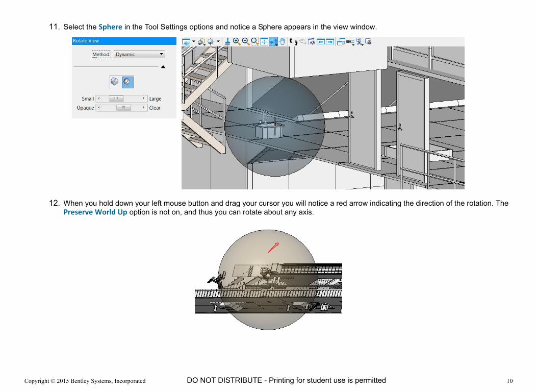
11. Select the Sphere in the Tool Settings options and notice a Sphere appears in the view window.
12. When you hold down your left mouse button and drag your cursor you will notice a red arrow indicating the direction of the rotation. The Preserve World Up option is not on, and thus you can rotate about any axis.

Copyright © 2015 Bentley Systems, Incorporated 11DO NOT DISTRIBUTE - Printing for student use is permitted
Hint: You can use the Slide bars to change the size of the sphere or change its opacity with the Opaque slider.
13. After rotating to a custom view you may want to save the view for later use for viewing or a drawing detail to clarify a design in your deliverables. We will go back to our Cube rotate with Preserve World Up enabled, then rotate to a custom view.

Copyright © 2015 Bentley Systems, Incorporated 12DO NOT DISTRIBUTE - Printing for student use is permitted
14. Navigate to the Saved View tool located in View > Saved Views > Create Saved View.
15. In the Tool Settings type a name for this view and a good Description so you can find this view for use at a later date. Click in View 2 to select the Source View. Navigate to the Saved View dialog by clicking on the button in lower right corner of the Saved Views tools.
Copyright © 2015 Bentley Systems, Incorporated 13DO NOT DISTRIBUTE - Printing for student use is permitted
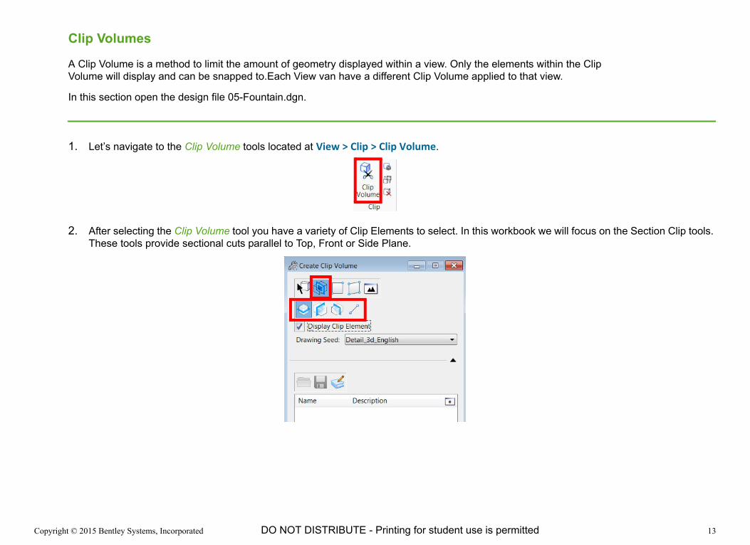
Clip Volumes
A Clip Volume is a method to limit the amount of geometry displayed within a view. Only the elements within the Clip Volume will display and can be snapped to.Each View van have a different Clip Volume applied to that view.
In this section open the design file 05-Fountain.dgn.
1. Let’s navigate to the Clip Volume tools located at View > Clip > Clip Volume.
2. After selecting the Clip Volume tool you have a variety of Clip Elements to select. In this workbook we will focus on the Section Clip tools. These tools provide sectional cuts parallel to Top, Front or Side Plane.

Copyright © 2015 Bentley Systems, Incorporated 14DO NOT DISTRIBUTE - Printing for student use is permitted
3. Fit All geometry in View 2 then select the fitted section parallel to the Top Plane. Enable Display Clip Element then click anywhere in View 2.
4. The blue handles control the amount of the clip to be displayed and the green arrow indicates the cutting plane. These can be modified by selecting and moving them.

Copyright © 2015 Bentley Systems, Incorporated 15DO NOT DISTRIBUTE - Printing for student use is permitted
5. To delete a Clip Volume for a specific view, click on the Clear Clip Volume icon.

Copyright © 2015 Bentley Systems, Incorporated 16DO NOT DISTRIBUTE - Printing for student use is permitted
Auxiliary Coordinate Systems (ACS)
An ACS is useful in placing elements on planes that have a different depth or orientation.In this section you will create a new ACS and draw 2D elements on the plane.
1. Open the design file 06-ACS Planes.dgn.

Copyright © 2015 Bentley Systems, Incorporated 17DO NOT DISTRIBUTE - Printing for student use is permitted
The objective is to create an ACS on the indicated plane.
2. Open the Manage ACS dialog by navigating to the lower right corner of Drawing Aids > ACS.

Copyright © 2015 Bentley Systems, Incorporated 18DO NOT DISTRIBUTE - Printing for student use is permitted
3. Some ACS have been created by default and these will be discussed in the section on AccuDraw in 3D. To create this new plane select the Define ACS (Aligned with Element) tool and click on the midpoint of the bottom edge of indicated plane above.
4. The next step is to create a name for the ACS. In the Manage ACS dialog select the Create a New ACS tool and name the ACS angled plane 1.
5. Create another ACS named angled plane 2 then select the Select ACS tool in the Manage ACS dialog. All available ACS are displayed. Click on any ACS to make it the Active ACS.

Copyright © 2015 Bentley Systems, Incorporated 19DO NOT DISTRIBUTE - Printing for student use is permitted
You can also Lock the ACS plane. This will force all X, Y and Z coordinates to be relative to the Active ACS, such as angled plane 2 above.
6. Navigate to Drawing Aids > Locks > Select ACS Plane Lock. The standard views are placed relative to the active ACS.

Copyright © 2015 Bentley Systems, Incorporated 20DO NOT DISTRIBUTE - Printing for student use is permitted
7. You can draw a Circle Element on the Plane in the Top View.
Try creating other shapes such as a Block, Ellipse, orthogonal shape, on angled plane 1.
Hint: Another method for making an ACS active is to double click the name in the Manage ACS dialog.
Copyright © 2015 Bentley Systems, Incorporated 21DO NOT DISTRIBUTE - Printing for student use is permitted
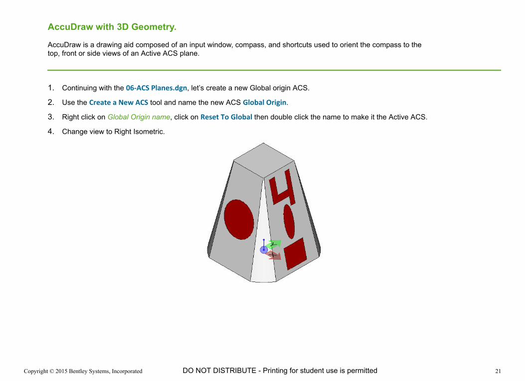
AccuDraw with 3D Geometry.
AccuDraw is a drawing aid composed of an input window, compass, and shortcuts used to orient the compass to the top, front or side views of an Active ACS plane.
1. Continuing with the 06-ACS Planes.dgn, let’s create a new Global origin ACS.
2. Use the Create a New ACS tool and name the new ACS Global Origin.
3. Right click on Global Origin name, click on Reset To Global then double click the name to make it the Active ACS.
4. Change view to Right Isometric.

Copyright © 2015 Bentley Systems, Incorporated 22DO NOT DISTRIBUTE - Printing for student use is permitted
5. You will draw a Block on the top of the 3D geometry. Remember the ACS lock is on, so elements will be drawn relative to the Global Origin ACS. If you were to create the Block away from the 3D object, the Block will be drawn on the Global Origin ACS. In the Front View notice the Block is drawn on the Global Origin ACS plane.
6. Draw the Block again but snap to the top of the 3D geometry. This will set the depth in the 3D View volume.

Copyright © 2015 Bentley Systems, Incorporated 23DO NOT DISTRIBUTE - Printing for student use is permitted
7. Open Design file AccuDraw compass orientation.
8. There are 3 basic compass orientations, the Top (T), Front (F), and Side (S) shortcuts. Remember from 2D training, Function Key (F11) places focus in AccuDraw, then type Shift+? to display the AccuDraw Shortcuts.Here are the 3 Compass orientation shortcuts in a Right Isometric View.

Copyright © 2015 Bentley Systems, Incorporated 24DO NOT DISTRIBUTE - Printing for student use is permitted
9. Open the Manage ACS dialog and you will see all the ACS planes. Some ACS planes have been created for top, front and side. By making one of these planes the Active plane then using the AccuSnap tools, you can set the depth to the top plane and draw elements on the top plane.
Copyright © 2015 Bentley Systems, Incorporated 25DO NOT DISTRIBUTE - Printing for student use is permitted
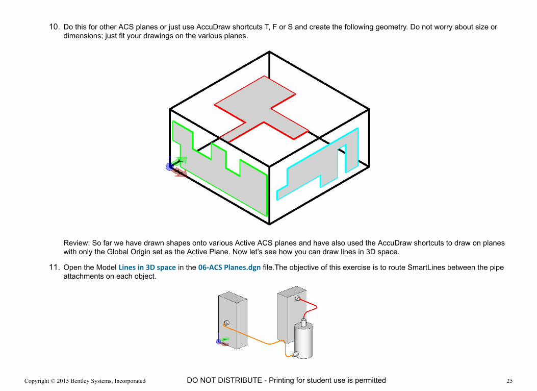
10. Do this for other ACS planes or just use AccuDraw shortcuts T, F or S and create the following geometry. Do not worry about size or dimensions; just fit your drawings on the various planes.
Review: So far we have drawn shapes onto various Active ACS planes and have also used the AccuDraw shortcuts to draw on planes with only the Global Origin set as the Active Plane. Now let’s see how you can draw lines in 3D space.
11. Open the Model Lines in 3D space in the 06-ACS Planes.dgn file.The objective of this exercise is to route SmartLines between the pipe attachments on each object.

Copyright © 2015 Bentley Systems, Incorporated 26DO NOT DISTRIBUTE - Printing for student use is permitted
12. Use a SmartLine with a Rounded Vertex of 0.200 Meters, and select the Center of the pipe attachment. Orient your compass to the (S), side or (T) top orientation, and move along the -X axis for 0.3 meters.
Note: You can change to Top standard view. With only one view window being used you can change to any standard view anytime.
13. Lock the axis in the positive Y axis by pressing Enter. This is the shortcut called Smart Lock. This allows you to move your cursor along the Y axis and align to the pipe attachment on the cylindrical object by moving the cursor to the pipe attachment point. Then press the left mouse button to add a data point.

Copyright © 2015 Bentley Systems, Incorporated 27DO NOT DISTRIBUTE - Printing for student use is permitted
14. To complete the routing of all the lines, use the following image as a guide

Copyright © 2015 Bentley Systems, Incorporated 28DO NOT DISTRIBUTE - Printing for student use is permitted
15. Simply draw a circle at the start point of each line, then use the Modeling > Solids > Extrude Along tool and create pipes as you see below.

Copyright © 2015 Bentley Systems, Incorporated 29DO NOT DISTRIBUTE - Printing for student use is permitted
Placing 3D Cells
In this section, we will open the Model Placing 3D cell in the MicroStation design file 07-3D Cells.dgn.
1. First navigate to the Drawing > Annotate > Cells > Place Active Cell tool.
2. Select the browse button (three dots) to the right of the Active Cell

Copyright © 2015 Bentley Systems, Incorporated 30DO NOT DISTRIBUTE - Printing for student use is permitted
The Cell Library dialog opens.
3. Select File > Attach File, then navigate to BentleyCONNECTTraining > WorkSets > Introduction To 3D > Cell Library > 3D Cells.cel.
4. Double click the Desk cell. This will make the Desk the Active Cell and it will appear at your cursor in View 2. You can close the Cell Library dialog.

Copyright © 2015 Bentley Systems, Incorporated 31DO NOT DISTRIBUTE - Printing for student use is permitted
5. The cell is in a top orientation but the view is right isometric.You will use the AccuDraw shortcut, letter O. This shortcut will place a temporary origin at the cursor (X). Remember to hover the cursor over a point until the “X” appears, then press the letter O.The cell will orient to the View 2 right isometric view.

Copyright © 2015 Bentley Systems, Incorporated 32DO NOT DISTRIBUTE - Printing for student use is permitted
The desk’s origin is now placed on the right side at corner between floor and wall. Use the Move tool to position the desk on the back wall. You may have to Rotate view if shaded or change to wireframe to see the back of Desk cell.
6. Now move the Desk cell along the negative X axis to position along the back wall.

Copyright © 2015 Bentley Systems, Incorporated 33DO NOT DISTRIBUTE - Printing for student use is permitted
7. Now let’s place a Desk cell along the left wall.
8. Select Place Cell tool. Hover over a point and press F11 then letter “O”. Rotate the Desk around the Z axis by typing shortcut RZ, then move to correct position.
The RZ tool rotates about the Z axis, RX about X axis and RY about Y axis. Try these other rotations to see results.

Copyright © 2015 Bentley Systems, Incorporated 34DO NOT DISTRIBUTE - Printing for student use is permitted
9. The creation of 3D cells is the same process as 2D cell creation.
a. Create geometry
b.Place all geometry in a Selection Set
c. Place a cell Origin
d. Change to Top View
e. Create a name for 3D cell
This exercise completes the Introduction To 3D course. Completion of this course is a prerequisite for all courses in MicroStation CONNECT Edition 3D.