get start 30 - telephone · pdf file1.1 system connection diagram ... telephone cable for...
TRANSCRIPT

Hybrid IP-PBX
Getting Started
1 Before Installation 2 Installation 3 Starting the Hybrid IP-PBX 4 Customising the Hybrid IP-PBX 5 Confirming the Connection
Table of Contents ........................... 2
........................................ 4............. 11
..... 14............ 20
Thank you for purchasing the Panasonic Hybrid IP-PBX, KX-TDA30.Please read this manual carefully before using this product and save this manual for future use.
KX-TDA30: Version 1.0
Model no. KX-TDA30

1 Before Installation
1.1 System Connection Diagram
*1 In addition to the supplied AC adaptor, an optional AC adaptor can be connected to the Hybrid IP-PBX.*2 The Hybrid IP-PBX has 4 super hybrid ports pre-installed.
SLT Wireless Phone Fax Machine
PCKX-T7636/KX-T7633
DSSConsole
Doorphone & Door Opener
AC Cord & AC Adaptor*1
IP-typePrivate Network
Station MessageDetail Recording (SMDR)
PC
Router
ISDN BRI LineISDN BRI Line(Digital Trunk)(Digital Trunk)ISDN BRI Line(Digital Trunk)
LCOT4(KX-TDA3180)
DLC8(KX-TDA3172)
DLC4(KX-TDA3171)
SLC8(KX-TDA3174)
SLC4(KX-TDA3173)
DPH4(KX-TDA3161)
DPH2(KX-TDA3162)
ECHO8(KX-TDA3166)
EXT-CID(KX-TDA3168)
MSG2(KX-TDA3191)
IP-GW4(KX-TDA3480)
AnalogueAnalogueTrunkTrunk
AnalogueTrunk
TelephoneCompany
SLT Wireless Phone Fax Machine
Hybrid IP-PBX
DPT
APT
DPT DSS Console
Voice Processing System
Voice Processing System
Radio
Amplifier Pager/Speaker
Server PC
CID4(KX-TDA3193)
CS PS
4 Super Hybrid Ports*2
CS PS
Batteries
Main Board
RMT(KX-TDA3196)
KX-T7600 DPT KX-T7600 DPT
for Single Line Device
for Digital Proprietary Telephone (DPT)and DSS Console
for Single Line Device, DPT/AnalogueProprietary Telephone(APT), DSS Console,and Portable Station (PS)
BRI2(KX-TDA3280)
2 Getting Started
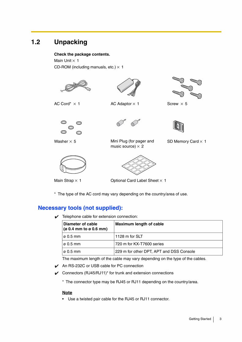
1.2 Unpacking
Check the package contents.
Main Unit × 1
CD-ROM (including manuals, etc.) × 1
Necessary tools (not supplied):Telephone cable for extension connection:
The maximum length of the cable may vary depending on the type of the cables.
An RS-232C or USB cable for PC connection
Connectors (RJ45/RJ11)* for trunk and extension connections
Note• Use a twisted pair cable for the RJ45 or RJ11 connector.
AC Cord* × 1 AC Adaptor × 1 Screw × 5
Washer × 5 Mini Plug (for pager andmusic source) × 2
SD Memory Card × 1
Main Strap × 1 Optional Card Label Sheet × 1
* The type of the AC cord may vary depending on the country/area of use.
Diameter of cable(ø 0.4 mm to ø 0.6 mm)
Maximum length of cable
ø 0.5 mm 1128 m for SLT
ø 0.5 mm 720 m for KX-T7600 series
ø 0.5 mm 229 m for other DPT, APT and DSS Console
* The connector type may be RJ45 or RJ11 depending on the country/area.
Getting Started 3

2 Installation
2.1 Opening/Closing the Covers
Opening the Covers1. Pull the slide button to the right and, holding it, slide the cable cover upwards. Then turn
the cable cover slightly to remove it.
2. Remove the three screws.
3. Holding the protrusions on both sides of the front cover, swing the cover open.
Slide Button
Cable Cover
Screw
4 Getting Started

Closing the Covers1. Close the front cover, then tighten the three screws.
2. Attach the rear hooks on the cable cover to the main unit, then swing the cable cover closed so that the front hooks fit in place.
3. Slide the cable cover down until it locks.
Screw
Cable Cover
Getting Started 5

2.2 Installing the SD Memory Card
The SD Memory Card contains software for all the processes of the Hybrid IP-PBX and all the customer data. The SD Memory Card must be inserted before start up.
CAUTIONDo not remove the SD Memory Card during the operation of the Hybrid IP-PBX. Removing the SD Memory Card during operation may cause damage to the SD Memory Card, or result in loss of data.
SD Memory CardSlot Cover
SD MemoryCard
6 Getting Started

2.3 Installing the Optional Service Cards
Slot Position
Slot Condition
The following table shows the slot condition. " " indicates that the slot supports the optional service card.
CAUTIONTo protect the main board from static electricity, do not touch parts on the main board or on the optional service cards. To discharge static, touch ground or wear an earthing strap.
*1 Slot s 10 and 11 supports only cards which do not have external ports. Therefore, these slots do not have removable cover plates.
*2 Slot 01 is the pre-installed super hybrid ports. No optional service card can be installed.
Card Slot Number
Type Max 02 03 04 05 06 07 08 09 10 11
LCOT4 3
BRI2 3
DLC41*1
*1 Only one of either DLC4 or SLC4 card can be installed.
SLC4
IP-GW4 1
DLC82*2
*2 A maximum of two DLC8 cards, two SLC8 cards, or one of each card can be installed.
SLC8
DPH41*3
*3 Only one of either DPH4 or DPH2 card can be installed.
DPH2
ECHO8 1
EXT-CID 1
MSG2 2
02
03
04
05
06
07
08
09
10*1
11*1
01*2
Getting Started 7

Installing the Trunk/Extension Cards1. Before installing the optional service cards, cut and remove the appropriate dummy cover
plates from the main unit.
CAUTIONFor safety reasons, smooth the cut edges after removing the dummy cover plates.
2. Position the card in the open slot, making sure that the tabs on the both sides of the card fit into place. Then, holding the card firmly in place, lower the rear end so that the hole of the card fits over the extension bolt.
3. Insert the new extension bolt (included with the card) into the hole on the card, and tighten it to secure the card.
Dummy Cover Plate
1
2
Extension Bolt
Optional Service Card
Extension Bolt
8 Getting Started

2.4 Installing the Trunk Cards
LCOT4 Card
Accessory (included): Extension Bolt × 1, Strap × 1
User-supplied (not included): RJ45 connector or RJ11 connector*
BRI2 Card
Accessory (included): Extension Bolt × 1, Strap × 1
User-supplied (not included): RJ45 connector
Notes• Connect this optional service card to the trunk through an NT1; do not connect to the
U interface of the trunk directly.
• This optional service card has 100 of terminal resistance. For use in point to multi-point connection, the card must be placed at the end of the bus.
* The connector type may be RJ45 or RJ11 depending on the country/area.
To trunk
RJ45
To NT1
RJ45 (LINE 1)RJ45 (LINE 2)
Getting Started 9

2.5 Installing the Extension Cards (DLC4/DLC8/SLC4/SLC8)
Accessory (included): Extension Bolt × 1, Strap × 1
User-supplied (not included): RJ45 connector or RJ11 connector*
2.6 Connecting Extensions
* The connector type may be RJ45 or RJ11 depending on the country/area.
Example: DLC4 Card
To extension
RJ45
To extension card
RJ11
Example: KX-T7600 Series DPT
DPT and DSS Console
KX-T7000 Series SLT
Pin Assignments
H L
T R
APT
HTRL
TO MAIN UNIT/ PABX
H L
10 Getting Started

2.7 Frame Earth Connection
IMPORTANT!Connect the frame of the Hybrid IP-PBX to earth.
• Proper earthing (connection to earth) is very important to protect the Hybrid IP-PBX from the bad effects of external noise or to reduce the risk to the user of electrocution in the case of lightning strikes.
• The earth wire of the AC cable has an effect against the external noise and lightning strikes, but it may not be enough to protect the Hybrid IP-PBX. A permanent connection between earth and the earth terminal of the Hybrid IP-PBX must be made.
3 Starting the Hybrid IP-PBX
CAUTION
• SD Memory Card must be inserted in the SD Memory Card slot of the main board before start up.
• Before touching the System Initialise Switch and the Reset Button, discharge static by touching ground or wearing an earthing strap.
• Once you have started the Hybrid IP-PBX and if you unplug the Hybrid IP-PBX, do not perform the following procedures to start the Hybrid IP-PBX again. Otherwise, your programmed data will be cleared.
• The Hybrid IP-PBX will continue to be powered even if the power switch is turned "OFF".
• The power supply cord is used as the main disconnect device, ensure that the socket-outlet is located/installed near the equipment and is easily accessible.
1. Loosen the screw.
2. Insert an earthing wire (user-supplied)*.
3. Tighten the screw.
4. Connect the earthing wire to earth.
* For earthing wire, green-and-yellow insulation is required, and the cross-sectional area of the conductor must be more than 0.75 mm2 or 18 AWG.
Screw
Earthingwire
To earth
Getting Started 11

1. Set the System Initialise Switch to the "SYSTEM INITIALIZE" position.
2. Plug the DC connector of the AC adaptor into the DC IN 1.
Note
The AC adaptor supplied with the Hybrid IP-PBX must be connected to the DC IN 1. If an AC adaptor is connected to the only DC IN 2, the Hybrid IP-PBX will not start.
Reset Button
System Initialise Switch
RUN Indicator
ALARM Indicator
DC Connector
DC IN 1
AC Adaptor
2
1
12 Getting Started

3. Plug the AC cord into the AC adaptor, and then plug the other end into an AC outlet.
4. Turn on the power switch.
Notes
• For safety reasons, follow the procedures as indicated when turning on the Hybrid IP-PBX.
• For safety reasons, do not stretch, bend, or pinch the AC cord and the DC cable of the AC adaptor.
5. Press the Reset Button with a pointed tool. (The RUN indicator will flash.)
6. While the RUN indicator is flashing (within about 10 s), return the System Initialise Switch to the “NORMAL” position. Depending on the configuration, initialisation takes about 1 min to 3 min. If successfully executed, the RUN indicator will stop flashing and be kept lit.
All data will be cleared and the Hybrid IP-PBX will be initialised to the default values. The DPTs should show the time as 01:00.
Note
Use the same types of AC adaptor and AC cord that are supplied with the Hybrid IP-PBX only.
AC Adaptor
AC Cord
To AC outlet
Power Switch
Getting Started 13

4 Customising the Hybrid IP-PBXKX-TDA30 Maintenance Console serves as an overall system programming tool for the Hybrid IP-PBX. KX-TDA30 Maintenance Console’s Quick Setup lets you easily configure the Hybrid IP-PBX to receive intercom and trunk calls, as well as apply basic settings such as time and date.
Note
The contents and design of the software are subject to change without notice.
4.1 Connecting the PC
To programme the Hybrid IP-PBX, connect it to the PC with serial interface.
Serial Interface Connection
PC
PC
To USB Port
To COM Port
USB Port
RS-232C Port
RS-232C (Cross Cable)Pin Assignments
Pin No.2345678
Pin No.2345678
RS-232C PortCOM Port
14 Getting Started

4.2 Installing the KX-TDA30 Maintenance Console and Selecting Appropriate Country/Area Data
For the system requirements of the PC (e.g., operating system, hardware specifications), refer to "7.3.1 Installing and Starting the KX-TDA30 Maintenance Console" in the Installation Manual.
NoteScreen shots reprinted with permission from Microsoft Corporation.
4.3 Programming the Hybrid IP-PBX
Starting the KX-TDA30 Maintenance Console and Assigning the Basic Items (Quick Setup)
When you start the KX-TDA30 Maintenance Console with the Installer Level Programmer Code and connect to the Hybrid IP-PBX for the first time after initialisation (with the factory default setting), Quick Setup will launch automatically. During Quick Setup, you will setup the following basic items:
• Date and Time of the Hybrid IP-PBX. The date and time set on the PC will be used.
• System Password for installer for PC programming.
• Operator extension numbers. Operator extensions for all time modes (day/lunch/break/night) can be assigned.
• Flexible Numbering type to pattern 1 or pattern 2. If pattern 1 (with ) is selected, " " must prefix all feature numbers (except access numbers) when an extension user wants to use a feature.
• Operator call and Idle Line Access/ARS numbers (0 or 9). The feature numbers for operator call and Idle Line Access/ARS can be selected.
• Remote Maintenance Dial Number. Enter the complete telephone number of the PBX (including the country code). When necessary, this number will be used to access the PBX from a remote location for maintenance purposes.
1. a. Save the setup file of the KX-TDA30 Maintenance Console on your PC.
b. Double-click the icon to execute the setup file.
c. Follow the instructions of the wizard.
2. a. Type the appropriate Country Code.The KX-TDA30 Maintenance Console will be installed with the appropriate default data for your country/area.
b. Click [Next].
c. Follow the instructions of the wizard.
d. Click [Finish].
e. Click [OK].
Getting Started 15

1 Start the KX-TDA30 Maintenance Console from the start menu.
2. a. Type the Installer Level Programmer Code (default: 1234).
b. Click [OK].
3. Click "Connect" "USB" or "RS-232C" from the menu bar, depending on the serial interface connection with the Hybrid IP-PBX.
NoteTo connect with USB, you need to have installed the KX-TDA USB driver. Follow the instructions of the wizard to install the KX-TDA USB driver.
4. a. Type the system password for installer (default: 1234).
b. Click [OK].
5. When country/area data do not match:
a. Click [OK] to replace the country/area data of the Hybrid IP-PBX. Replacement may take several minutes to complete.
b. Follow the procedure described in "3 Starting the Hybrid IP-PBX" and restart the Hybrid IP-PBX.
c. Repeat steps 1 to 4 to restart the KX-TDA30 Maintenance Console.
6. Follow the instructions of the wizard and assign the basic items (Quick Setup).
16 Getting Started

Assigning the BRI Setting (Automatic Configuration)
The programme menu appears.
1. a. Double-click "Configuration".
b. Double-click "Slot".
c. Change the status of the BRI card to OUS.
d. Click [Cancel].
2. Click "Tool" "BRI Automatic Configuration" from the menu bar.
3. a. Click "Check" to turn on the BRI card.
b. Click [OK].
Getting Started 17

Assigning the Incoming Trunk Call Destination
4. a. Type the Subscriber Number for the desired ports.
b. Click [Execute].ISDN line data such as P-P/P-MP, TEI Mode are automatically set.
c. Click "Check Box" of the desired ports.
d. Click [Data Apply].
e. Click [Close].
5. a. Double-click "Slot".b. Change the status of the BRI card to INS.
c. Click [Cancel].
For analogue trunk user (DIL Setting):
1. Double-click "CO & Incoming Call".2. Double-click "DIL Table & Port Setting".
3. Click the "DIL" tab.
4. For necessary items, enter the proper numbers and selections.
5. Click [OK].
For ISDN trunk user (DDI Setting):
1. Double-click "CO & Incoming Call".2. Double-click "DDI/DID Table".
3. For necessary items, enter the proper numbers and selections.
4. Click [OK].
18 Getting Started

Setting the Extension Port for Using DSS Console
For ISDN trunk user (MSN Setting):
1. Double-click "CO & Incoming Call".2. Double-click "DIL Table & Port Setting".
3. Click the "DDI / DID / TIE / MSN" tab.
4. Set the "Incoming Type" of the desired ports to "MSN".
5. Click [OK].
6. Double-click "MSN Table".
7. Click the "Main" tab.
8. For necessary items, enter the proper numbers and selections.
9. Click [OK].
1. Double-click "Configuration".
2. Double-click "Extension Port".
3. Change the connection of the desired port to OUS.
4. For DPT Property, set the Type to "DSS" and assign the Location number.
5. Click [OK].
6. Double-click "Extension".
7. Double-click "DSS Console".
8. Double-click "Main".
9. Type the Pair Extension Number.
10. Click [OK].
11. Double-click "Flexible Key".
12. For necessary items, enter the proper numbers and selections.
13. Click [OK].
Getting Started 19

5 Confirming the Connection
5.1 Making Calls
To call another extension
To call an outside party
14. Double-click "Configuration".
15. Double-click "Extension Port".16. Change the connection of the
appropriate port to INS.
17. Click [OK].
Off-hook. Talk.Dial extension number.
extension no.
Off-hook. Talk.Dial outside phone number.
Enter automatic line access number.
9 0/ outsidephone no.
20 Getting Started

Getting Started 21

The KX-TDA30E, the KX-TDA30NE, the KX-TDA30GR, and the KX-TDA30CE are designed to interwork with the:• Analogue Public Switched Telephone Network (PSTN) of a European country• Pan-European Integrated Services Digital Network (ISDN) using ISDN basic rate access
We, Panasonic Communications Co., Ltd./Panasonic Communications Company (U.K.) Ltd., declare that this equipment is in compliance with the essential requirements and other relevant provisions of Directive 1999/5/EC.If you would like to receive a copy of the original Declaration of Conformity of our products which relates to the R&TTE, please visit our web address:http://doc.panasonic-tc.de
Panasonic Communications Co., Ltd.1-62, 4-chome, Minoshima, Hakata-ku, Fukuoka 812-8531, Japan
Copyright:This manual is copyrighted by Panasonic Communications Co., Ltd. (PCC). You may print out this manual solely for internal use with this model. Except above, you may not reproduce this manual in any form, in whole or part, without the prior written consent of PCC.
© 2003 Panasonic Communications Co., Ltd. All Rights Reserved.
PSQX3128ZA KK1103EK0