geotechnical engineering report structure pipe jacking.pdf · geotechnical engineering report...
TRANSCRIPT

Geotechnical Engineering Report Turner Turnpike Widening
Milepost 210 to 218
Drainage Structure Pipe Jacking
Creek County, Oklahoma
July 1, 2016
Terracon Project No. 04165017
Prepared for:
Benham
Tulsa, Oklahoma
Prepared by:
Terracon Consultants, Inc.
Tulsa, Oklahoma


TABLE OF CONTENTS
Page
Responsive ■ Resourceful ■ Reliable
INTRODUCTION ............................................................................................................. 1
PROJECT INFORMATION ............................................................................................. 1
2.1 Project Description ............................................................................................... 1
2.2 Site Location and Description .............................................................................. 1
SUBSURFACE CONDITIONS ........................................................................................ 2
3.1 Soil Conditions ..................................................................................................... 2
3.2 Groundwater ........................................................................................................ 2
PIPE JACKING CONSIDERATIONS .............................................................................. 3
4.1 Pipe Jacking at Station 887+27 ............................................................................ 3
GENERAL COMMENTS ................................................................................................. 3
APPENDIX A – FIELD EXPLORATION
Exhibit A-1 Site Location Map
Exhibit A-2 Boring Location Plans
Exhibit A-3 Field Exploration Description
Exhibits A-4 to A-5 Boring Logs
Exhibit A-6 Subsurface Profile
APPENDIX B – SUPPORTING INFORMATION
Exhibit B-1 Laboratory Testing
Exhibits B-2 Grain Size Distribution
APPENDIX C – SUPPORTING DOCUMENTS
Exhibit C-1 General Notes
Exhibit C-2 Unified Soil Classification System
Exhibit C-3 AASHTO Soil Classification System
Responsive ■ Resourceful ■ Reliable 1
GEOTECHNICAL ENGINEERING REPORT
TURNER TURNPIKE WIDENING
PIPE JACKING
CREEK COUNTY, OKLAHOMA
Terracon Project No. 04165017
July 1, 2016
INTRODUCTION
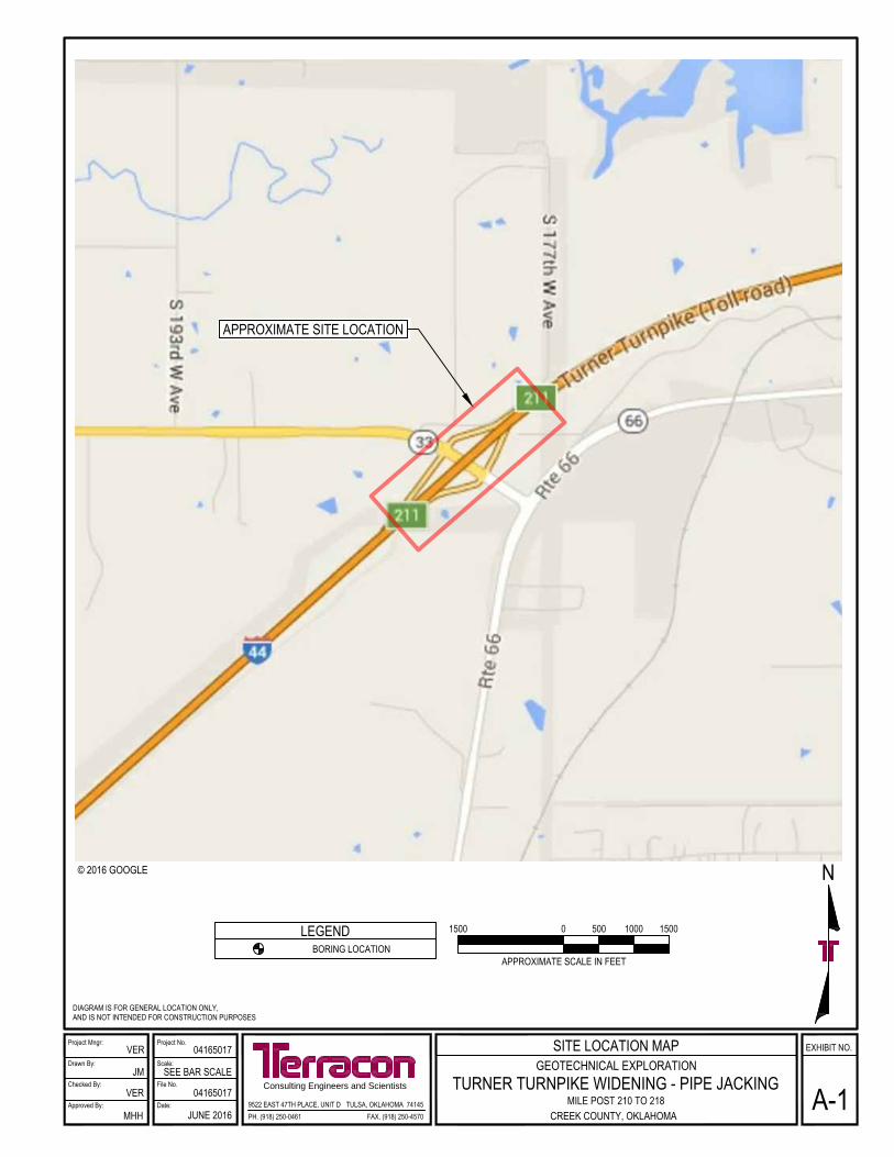
This geotechnical engineering report has been completed for the proposed pipe jacking location
along the Turner Turnpike in Creek County, Oklahoma (Appendix A, Exhibit A-1). Two borings,
designated PJ-1A and PJ-1B, were drilled for the project to depths of approximately 12.5 to 18.5
feet below the existing ground surface. The boring logs and a boring location plan showing the
approximate boring locations are provided in Appendix A of this report.
The purpose of these services is to provide information and geotechnical engineering
recommendations relative to:
subsurface soil and rock conditions pipe jacking
groundwater conditions
PROJECT INFORMATION
2.1 Project Description
Item Description
Boring Layout See Appendix A, Figure A-2 Boring Location Diagram.
Proposed Construction Pipe jacking will be performed to replace an existing reinforced
concrete pipe.
2.2 Site Location and Description
Item Description
Location
Crossing beneath I-44 (Turner Turnpike) in Creek County, Oklahoma
at Station 887+27. The pipe will have a flowline of from about 819.4
feet to 818.5 feet.
Geotechnical Engineering Report
Turner Turnpike Widening – Utility Pipe Jacking
Creek County, Oklahoma ■ July 1, 2016 ■ Terracon Project No. 04165017
Responsive ■ Resourceful ■ Reliable 2
SUBSURFACE CONDITIONS
3.1 Soil Conditions
The subsurface conditions encountered in the borings are shown on the boring logs and are briefly
described below. The stratification lines shown on the boring logs (Exhibits A-4 to A-5, Appendix A)
represent the approximate boundary between soil types; in-situ, the transition between materials
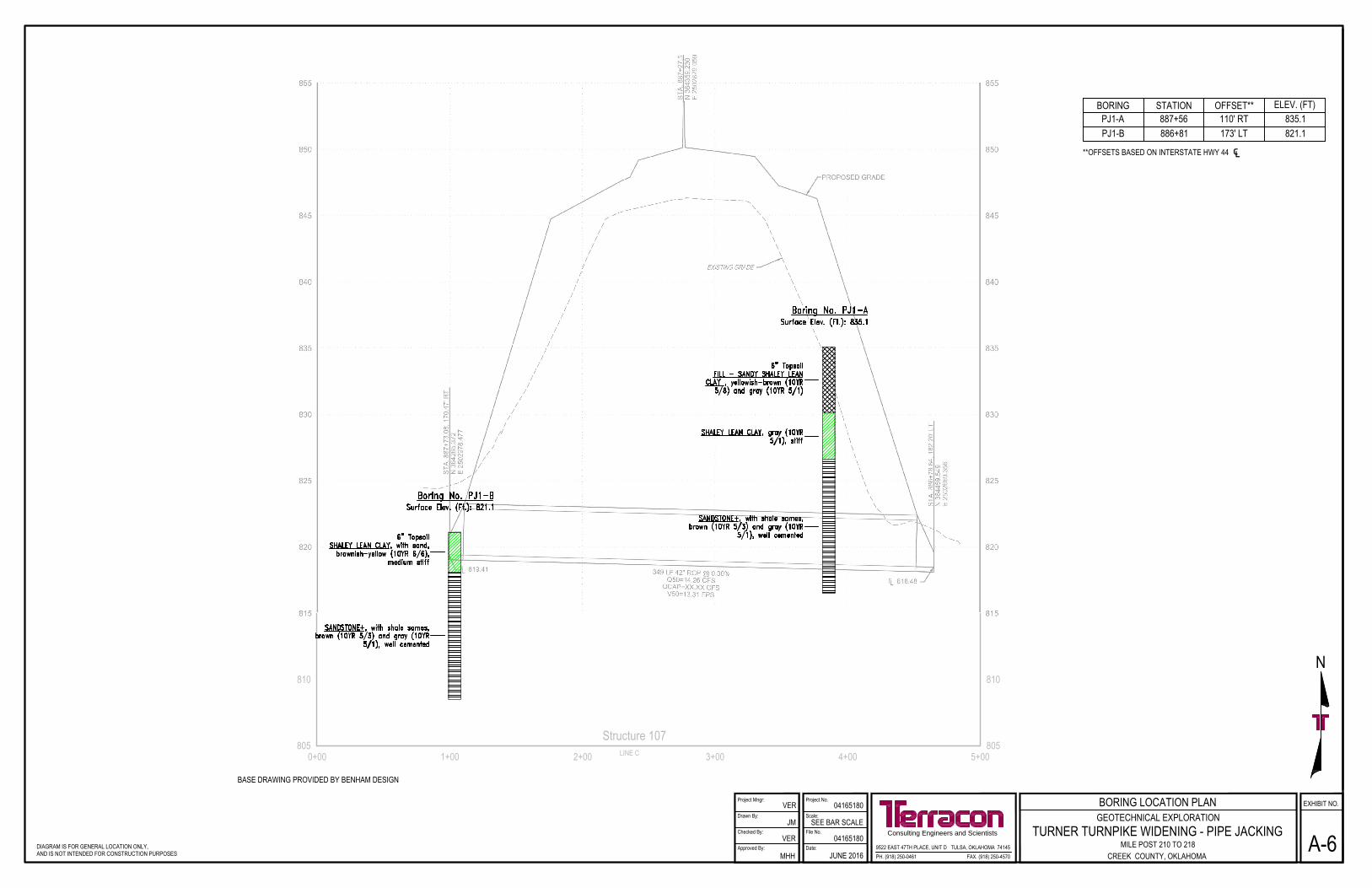
may be gradual and indistinct. Exhibit A-6 of Appendix A shows profiles of the pipe jacking location
with boring logs superimposed over the cross section.
Description Approximate Depth to
Bottom of Stratum Material Encountered Consistency/Density
Surface 6 inches Topsoil N/A
Stratum 1 5 feet at boring PJ1-A Fill: Sandy shaley lean clay N/A
Stratum 2 3 to 8.5 feet Shaley lean clay Medium stiff to stiff
Stratum 3
Encountered to boring
termination depths of
about 12.5 to 18.5 feet
Sandstone with shale seams Well cemented
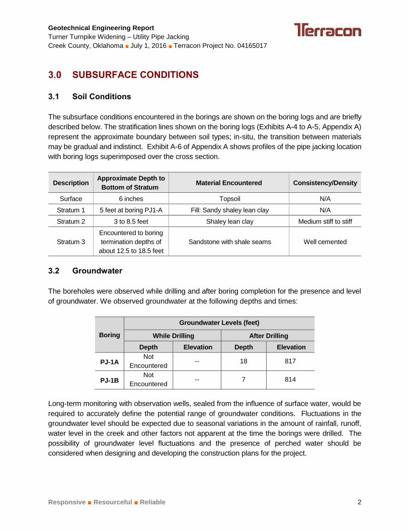
3.2 Groundwater
The boreholes were observed while drilling and after boring completion for the presence and level
of groundwater. We observed groundwater at the following depths and times:
Boring
Groundwater Levels (feet)
While Drilling After Drilling
Depth Elevation Depth Elevation
PJ-1A Not
Encountered -- 18 817
PJ-1B Not
Encountered -- 7 814
Long-term monitoring with observation wells, sealed from the influence of surface water, would be
required to accurately define the potential range of groundwater conditions. Fluctuations in the
groundwater level should be expected due to seasonal variations in the amount of rainfall, runoff,
water level in the creek and other factors not apparent at the time the borings were drilled. The
possibility of groundwater level fluctuations and the presence of perched water should be
considered when designing and developing the construction plans for the project.

Geotechnical Engineering Report
Turner Turnpike Widening – Utility Pipe Jacking
Creek County, Oklahoma ■ July 1, 2016 ■ Terracon Project No. 04165017
Responsive ■ Resourceful ■ Reliable 3
PIPE JACKING CONSIDERATIONS
4.1 Pipe Jacking at Station 887+27
Based on the results of the borings, the pipe at Station 887+27 will encounter medium stiff to very
stiff native clay and well cemented, hard sandstone with shale seams. Special installation
techniques such as pre-drilling will be required to penetrate the sandstone bedrock within the
zone of the proposed pipe.
We understand that headwalls may be constructed after pipe jacking activities are completed.
Construction activities for performing pipe jacking may disturb the soils in this area. Thus, we
recommend proofrolling be performed within the areas of proposed headwall construction with a
loaded tandem axle dump truck weighing at least 25 tons or the equivalent. A review of aerial
photography indicate areas of standing water near the outlet of the concrete pipe at the toe of the
existing embankment. If soft, wet soils are present during construction, these soils may be
unstable for the support of construction equipment, and it will be necessary to overexcavate and
replace, with compact soil or crushed aggregate, or stabilize the full-depth of the unstable soils to
develop support for equipment and allow headwall construction to proceed.
GENERAL COMMENTS
Terracon should be retained to review the final design plans and specifications so comments can
be made regarding interpretation and implementation of our geotechnical recommendations in
the design and specifications. Terracon also should be retained to provide observation and testing
services during grading, excavation, foundation construction and other earth-related construction
phases of the project.
The analysis and recommendations presented in this report are based upon the data obtained
from the borings performed at the indicated locations and from other information discussed in this
report. This report does not reflect variations that may occur between borings, across the site, or
due to the modifying effects of construction or weather. The nature and extent of such variations
may not become evident until during or after construction. If variations appear, we should be
immediately notified so that further evaluation and supplemental recommendations can be
provided.
The scope of services for this project does not include either specifically or by implication any
environmental assessment of the site or identification or prevention of pollutants, hazardous
materials or conditions. If the owner is concerned about the potential for such contamination or
pollution, other studies should be undertaken.
Geotechnical Engineering Report
Turner Turnpike Widening – Utility Pipe Jacking
Creek County, Oklahoma ■ July 1, 2016 ■ Terracon Project No. 04165017
Responsive ■ Resourceful ■ Reliable 4
This report has been prepared for the exclusive use of our client for specific application to the
project discussed and has been prepared in accordance with generally accepted geotechnical
engineering practices. No warranties, either express or implied, are intended or made. Site safety,
excavation support, and dewatering requirements are the responsibility of others. In the event
that changes in the nature, design, or location of the project as outlined in this report are planned,
the conclusions and recommendations contained in this report shall not be considered valid
unless Terracon reviews the changes and either verifies or modifies the conclusions of this report
in writing.
APPENDIX A
FIELD EXPLORATION
N
APPROXIMATE SITE LOCATION
LEGENDBORING LOCATION
DIAGRAM IS FOR GENERAL LOCATION ONLY, AND IS NOT INTENDED FOR CONSTRUCTION PURPOSES
© 2016 GOOGLE
APPROXIMATE SCALE IN FEET
1500 0 1000 1500500
Project Mngr:
Approved By:
Checked By:
Drawn By:
Project No.
Scale:
Date:
File No.Consulting Engineers and Scientists
EXHIBIT NO.
9522 EAST 47TH PLACE, UNIT D TULSA, OKLAHOMA 74145FAX. (918) 250-4570PH. (918) 250-0461
VER
JM
VER
MHH
04165017
SEE BAR SCALE
04165017
JUNE 2016
SITE LOCATION MAP
A-1GEOTECHNICAL EXPLORATION
TURNER TURNPIKE WIDENING - PIPE JACKINGMILE POST 210 TO 218
CREEK COUNTY, OKLAHOMA
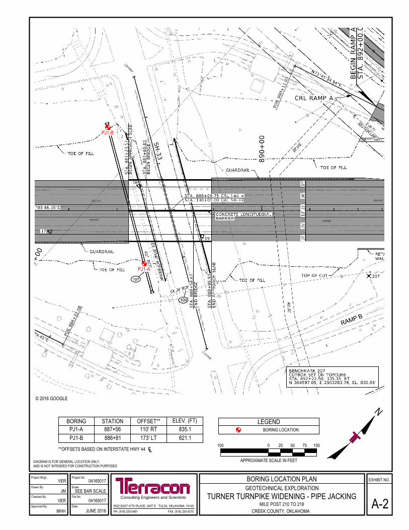
BORING STATION OFFSET** ELEV. (FT)PJ1-A 887+56 110' RT 835.1PJ1-B 886+81 173' LT 821.1
**OFFSETS BASED ON INTERSTATE HWY 44 ℄
LEGENDBORING LOCATION
DIAGRAM IS FOR GENERAL LOCATION ONLY, AND IS NOT INTENDED FOR CONSTRUCTION PURPOSES
© 2016 GOOGLE
APPROXIMATE SCALE IN FEET
100 0 50 1007525
Project Mngr:
Approved By:
Checked By:
Drawn By:
Project No.
Scale:
Date:
File No.Consulting Engineers and Scientists
EXHIBIT NO.
9522 EAST 47TH PLACE, UNIT D TULSA, OKLAHOMA 74145FAX. (918) 250-4570PH. (918) 250-0461
VER
JM
VER
MHH
04165017
SEE BAR SCALE
04165017
JUNE 2016
BORING LOCATION PLAN
A-2GEOTECHNICAL EXPLORATION
TURNER TURNPIKE WIDENING - PIPE JACKINGMILE POST 210 TO 218
CREEK COUNTY, OKLAHOMA
PJ1-B
PJ1-A
Geotechnical Engineering Report
Turner Turnpike Widening – Utility Pipe Jacking
Creek County, Oklahoma ■ July 1, 2016 ■ Terracon Project No. 04165017
Responsive ■ Resourceful ■ Reliable Exhibit A-3
Field Exploration Description
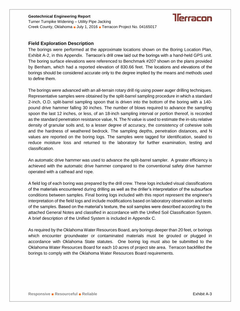
The borings were performed at the approximate locations shown on the Boring Location Plan,
Exhibit A-2, in this Appendix. Terracon’s drill crew laid out the borings with a hand-held GPS unit.
The boring surface elevations were referenced to Benchmark #207 shown on the plans provided
by Benham, which had a reported elevation of 830.66 feet. The locations and elevations of the
borings should be considered accurate only to the degree implied by the means and methods used
to define them.
The borings were advanced with an all-terrain rotary drill rig using power auger drilling techniques.
Representative samples were obtained by the split-barrel sampling procedure in which a standard
2-inch, O.D. split-barrel sampling spoon that is driven into the bottom of the boring with a 140-
pound drive hammer falling 30 inches. The number of blows required to advance the sampling
spoon the last 12 inches, or less, of an 18-inch sampling interval or portion thereof, is recorded
as the standard penetration resistance value, N. The N value is used to estimate the in-situ relative
density of granular soils and, to a lesser degree of accuracy, the consistency of cohesive soils
and the hardness of weathered bedrock. The sampling depths, penetration distances, and N
values are reported on the boring logs. The samples were tagged for identification, sealed to
reduce moisture loss and returned to the laboratory for further examination, testing and
classification.
An automatic drive hammer was used to advance the split-barrel sampler. A greater efficiency is
achieved with the automatic drive hammer compared to the conventional safety drive hammer
operated with a cathead and rope.
A field log of each boring was prepared by the drill crew. These logs included visual classifications
of the materials encountered during drilling as well as the driller’s interpretation of the subsurface
conditions between samples. Final boring logs included with this report represent the engineer's
interpretation of the field logs and include modifications based on laboratory observation and tests
of the samples. Based on the material’s texture, the soil samples were described according to the
attached General Notes and classified in accordance with the Unified Soil Classification System.
A brief description of the Unified System is included in Appendix C.
As required by the Oklahoma Water Resources Board, any borings deeper than 20 feet, or borings
which encounter groundwater or contaminated materials must be grouted or plugged in
accordance with Oklahoma State statutes. One boring log must also be submitted to the
Oklahoma Water Resources Board for each 10 acres of project site area. Terracon backfilled the
borings to comply with the Oklahoma Water Resources Board requirements.

69
96
14
15
11
10
9
28-16-12
35-18-17
830
826.5
816.5
12
1
14
0
12
1
4-3-2N=5
1-2-2N=4
4-6-7N=13
50/1"
14-50/6"
50/1"
5.0
8.5
18.6
6" TopsoilFILL - SANDY SHALEY LEAN CLAY , yellowish-brown(10YR 5/8) and gray (10YR 5/1)
SHALEY LEAN CLAY, gray (10YR 5/1), stiff
SANDSTONE+, with shale sames, brown (10YR 5/3) andgray (10YR 5/1), well cemented
Boring Terminated at 18.6 Feet
Hammer Type: Automatic+Classification estimated from disturbed samples. Coresamples and petrographic analysis may reveal other rock types.
Stratification lines are approximate. In-situ, the transition may be gradual.
GR
AP
HIC
LO
G
TH
IS B
OR
ING
LO
G IS
NO
T V
ALI
D IF
SE
PA
RA
TE
D F
RO
M O
RIG
INA
L R
EP
OR
T.
G
EO
SM
AR
T L
OG
-NO
WE
LL 0
416
501
7 P
IPE
JA
CK
.GP
J
Mile Post 210 to 218 Creek County, OklahomaSITE:
Page 1 of 1
Advancement Method:Power Auger
Abandonment Method:Backfilled with cuttings above 4’; grouted 4’ to 14’;backfilled with cuttings from 14’ to termination depth.
9522 E 47th Pl Ste DTulsa, OK
Notes:
Project No.: 04165017
Drill Rig: ATV 840
Boring Started: 6/25/2016
BORING LOG NO. PJ1-ABenhamCLIENT:
Driller: JB
Boring Completed: 6/25/2016
Exhibit: A-1
See Exhibit A-3 for description of fieldprocedures.See Appendix C for description of laboratoryprocedures and additional data (if any).
See Appendix C for explanation of symbols andabbreviations.
PROJECT: Turner Turnpike Widening - Pipe Jacking
PE
RC
EN
T F
INE
S
WA
TE
RC
ON
TE
NT
(%
)
ATTERBERGLIMITS
LL-PL-PISurface Elev.: 835.1 (Ft.)
ELEVATION (Ft.)
SA
MP
LE T
YP
E
WA
TE
R L
EV
EL
OB
SE
RV
AT
ION
S
DE
PT
H (
Ft.)
5
10
15
RE
CO
VE
RY
(In
.)
UN
CO
NF
INE
DC
OM
PR
ES
SIV
ES
TR
EN
GT
H (
psi)
FIE
LD T
ES
TR
ES
ULT
S
DEPTH
LOCATION See Exhibit A-2
Station: 887+56 Offset: 110' RTNorthing: 0 Easting: 1
WATER LEVEL OBSERVATIONS
18 ft After Drilling
Not Encountered While Drilling
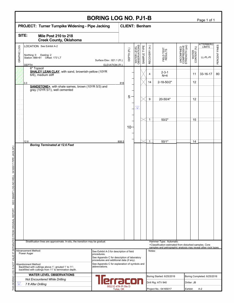
8011
12
12
15
14
33-16-17
818
808.5
4
14
9
1
1
2-3-1N=4
2-18-50/2"
20-50/4"
50/2"
50/1"
3.0
12.6
6" TopsoilSHALEY LEAN CLAY, with sand, brownish-yellow (10YR6/6), medium stiff
SANDSTONE+, with shale sames, brown (10YR 5/3) andgray (10YR 5/1), well cemented
Boring Terminated at 12.6 Feet
Hammer Type: Automatic+Classification estimated from disturbed samples. Coresamples and petrographic analysis may reveal other rock types.
Stratification lines are approximate. In-situ, the transition may be gradual.
GR
AP
HIC
LO
G
TH
IS B
OR
ING
LO
G IS
NO
T V
ALI
D IF
SE
PA
RA
TE
D F
RO
M O
RIG
INA
L R
EP
OR
T.
G
EO
SM
AR
T L
OG
-NO
WE
LL 0
416
501
7 P
IPE
JA
CK
.GP
J
Mile Post 210 to 218 Creek County, OklahomaSITE:
Page 1 of 1
Advancement Method:Power Auger
Abandonment Method:Backfilled with cuttings above 1’; grouted 1’ to 11’;backfilled with cuttings from 11’ to termination depth.
9522 E 47th Pl Ste DTulsa, OK
Notes:
Project No.: 04165017
Drill Rig: ATV 840
Boring Started: 6/25/2016
BORING LOG NO. PJ1-BBenhamCLIENT:
Driller: JB
Boring Completed: 6/25/2016
Exhibit: A-2
See Exhibit A-3 for description of fieldprocedures.See Appendix C for description of laboratoryprocedures and additional data (if any).
See Appendix C for explanation of symbols andabbreviations.
PROJECT: Turner Turnpike Widening - Pipe Jacking
PE
RC
EN
T F
INE
S
WA
TE
RC
ON
TE
NT
(%
)
ATTERBERGLIMITS
LL-PL-PISurface Elev.: 821.1 (Ft.)
ELEVATION (Ft.)
SA
MP
LE T
YP
E
WA
TE
R L
EV
EL
OB
SE
RV
AT
ION
S
DE
PT
H (
Ft.)
5
10
RE
CO
VE
RY
(In
.)
UN
CO
NF
INE
DC
OM
PR
ES
SIV
ES
TR
EN
GT
H (
psi)
FIE
LD T
ES
TR
ES
ULT
S
DEPTH
LOCATION See Exhibit A-2
Station: 886+81 Offset: 173' LTNorthing: 0 Easting: 2
WATER LEVEL OBSERVATIONS
7 ft After Drilling
Not Encountered While Drilling
810
805
810
8050+00 1+00 2+00 3+00 4+00 5+00
Structure 107LINE C
Project Mngr:
Approved By:
Checked By:
Drawn By:
Project No.
Scale:
Date:
File No.Consulting Engineers and Scientists
EXHIBIT NO.
9522 EAST 47TH PLACE, UNIT D TULSA, OKLAHOMA 74145FAX. (918) 250-4570PH. (918) 250-0461
VER
JM
VER
MHH
04165180
SEE BAR SCALE
04165180
JUNE 2016
BORING LOCATION PLAN
A-6GEOTECHNICAL EXPLORATION
TURNER TURNPIKE WIDENING - PIPE JACKINGMILE POST 210 TO 218
CREEK COUNTY, OKLAHOMA
N
DIAGRAM IS FOR GENERAL LOCATION ONLY, AND IS NOT INTENDED FOR CONSTRUCTION PURPOSES
BASE DRAWING PROVIDED BY BENHAM DESIGN
BORING STATION OFFSET** ELEV. (FT)PJ1-A 887+56 110' RT 835.1PJ1-B 886+81 173' LT 821.1
**OFFSETS BASED ON INTERSTATE HWY 44 ℄
APPENDIX B
SUPPORTING INFORMATION

Geotechnical Engineering Report
Turner Turnpike Widening – Utility Pipe Jacking
Creek County, Oklahoma ■ July 1, 2016 ■ Terracon Project No. 04165017
Responsive ■ Resourceful ■ Reliable Exhibit B-1
Laboratory Testing
Samples retrieved during the field exploration were taken to the laboratory for further observation
by the project geotechnical engineer and were classified in accordance with the Unified Soil
Classification System (USCS) described in Appendix C. After the testing was completed, the field
descriptions were confirmed or modified as necessary.
Selected soil and bedrock samples obtained from the site were tested for the following
engineering properties:
Water content (ASTM D2216)
Atterberg limits (ASTM D4318)
Sieve analysis (ASTM D422)
Procedural standards noted above are for reference to methodology in general. In some cases
variations to methods are applied as a result of local practice or professional judgment.

APPENDIX C
SUPPORTING DOCUMENTS
01 - 1011 - 30
> 30
RELATIVE PROPORTIONS OF FINES
Descriptive Term(s)of other constituents
Percent ofDry Weight
Hand Penetrometer
Torvane
Standard PenetrationTest (blows per foot)
Photo-Ionization Detector
Organic Vapor Analyzer
Texas Cone Penetrometer
TraceWithModifier
Water Level Aftera Specified Period of Time
GRAIN SIZE TERMINOLOGYRELATIVE PROPORTIONS OF SAND AND GRAVEL
TraceWithModifier
Standard Penetration orN-Value
Blows/Ft.
Descriptive Term(Consistency)
Loose
Very Stiff
Standard Penetration orN-Value
Blows/Ft.
Ring SamplerBlows/Ft.
Ring SamplerBlows/Ft.
Medium Dense
Dense
Very Dense
0 - 1 < 3
4 - 9 2 - 4 3 - 4
Medium-Stiff 5 - 9
30 - 50
WA
TE
R L
EV
EL
Auger
Shelby Tube
Grab Sample
FIE
LD
TE
ST
S
DESCRIPTION OF SYMBOLS AND ABBREVIATIONS
Descriptive Term(Density)
Non-plasticLowMediumHigh
BouldersCobblesGravelSandSilt or Clay
10 - 18
> 50 15 - 30 19 - 42
> 30 > 42
_
Water levels indicated on the soil boringlogs are the levels measured in theborehole at the times indicated.Groundwater level variations will occurover time. In low permeability soils,accurate determination of groundwaterlevels is not possible with short termwater level observations.
CONSISTENCY OF FINE-GRAINED SOILS
(50% or more passing the No. 200 sieve.)Consistency determined by laboratory shear strength testing, field
visual-manual procedures or standard penetration resistance
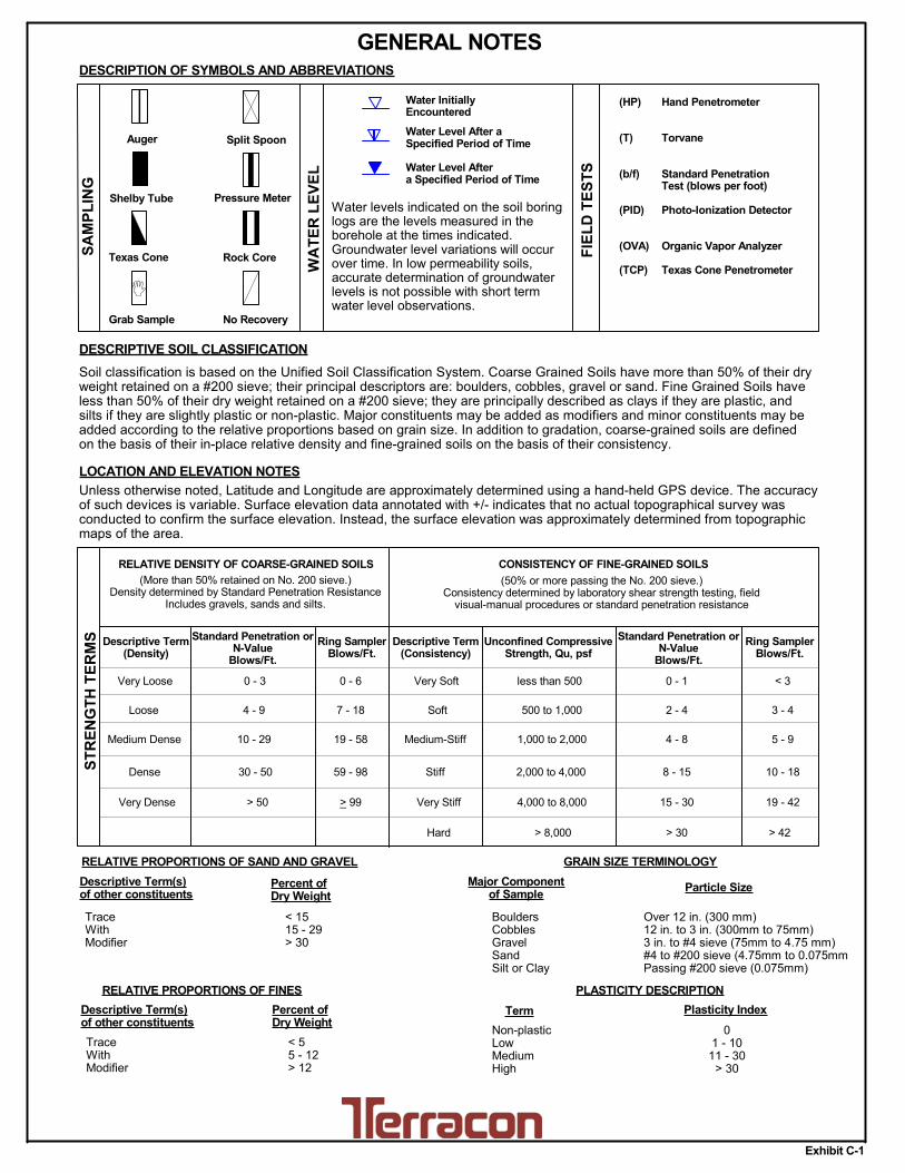
DESCRIPTIVE SOIL CLASSIFICATION
> 8,000
Unless otherwise noted, Latitude and Longitude are approximately determined using a hand-held GPS device. The accuracyof such devices is variable. Surface elevation data annotated with +/- indicates that no actual topographical survey wasconducted to confirm the surface elevation. Instead, the surface elevation was approximately determined from topographicmaps of the area.
Soil classification is based on the Unified Soil Classification System. Coarse Grained Soils have more than 50% of their dryweight retained on a #200 sieve; their principal descriptors are: boulders, cobbles, gravel or sand. Fine Grained Soils haveless than 50% of their dry weight retained on a #200 sieve; they are principally described as clays if they are plastic, andsilts if they are slightly plastic or non-plastic. Major constituents may be added as modifiers and minor constituents may beadded according to the relative proportions based on grain size. In addition to gradation, coarse-grained soils are definedon the basis of their in-place relative density and fine-grained soils on the basis of their consistency.
Plasticity Index
8 - 15
Split Spoon
Rock Core
PLASTICITY DESCRIPTION
Term
< 1515 - 29> 30
Descriptive Term(s)of other constituents
Water InitiallyEncountered
Water Level After aSpecified Period of Time
Major Componentof Sample
Percent ofDry Weight
(More than 50% retained on No. 200 sieve.)Density determined by Standard Penetration Resistance
Includes gravels, sands and silts.
Hard
Very Loose 0 - 3 0 - 6 Very Soft
7 - 18 Soft
10 - 29 19 - 58
59 - 98 Stiff
less than 500
500 to 1,000
1,000 to 2,000
2,000 to 4,000
4,000 to 8,000> 99
LOCATION AND ELEVATION NOTES
SA
MP
LIN
G
< 55 - 12> 12
No Recovery
RELATIVE DENSITY OF COARSE-GRAINED SOILS
Particle Size
Over 12 in. (300 mm)12 in. to 3 in. (300mm to 75mm)3 in. to #4 sieve (75mm to 4.75 mm)#4 to #200 sieve (4.75mm to 0.075mmPassing #200 sieve (0.075mm)
ST
RE
NG
TH
TE
RM
S Unconfined CompressiveStrength, Qu, psf
4 - 8
GENERAL NOTES
Texas Cone
(HP)
(T)
(b/f)
(PID)
(OVA)
(TCP)
Pressure Meter
Exhibit C-1

UNIFIED SOIL CLASSIFICATION SYSTEM
Criteria for Assigning Group Symbols and Group Names Using Laboratory Tests A Soil Classification
Group Symbol
Group Name B
Coarse Grained Soils: More than 50% retained on No. 200 sieve
Gravels: More than 50% of coarse fraction retained on No. 4 sieve
Clean Gravels: Less than 5% fines C
Cu 4 and 1 Cc 3 E GW Well-graded gravel F
Cu 4 and/or 1 Cc 3 E GP Poorly graded gravel F
Gravels with Fines: More than 12% fines C
Fines classify as ML or MH GM Silty gravel F,G,H
Fines classify as CL or CH GC Clayey gravel F,G,H
Sands: 50% or more of coarse fraction passes No. 4 sieve
Clean Sands: Less than 5% fines D
Cu 6 and 1 Cc 3 E SW Well-graded sand I
Cu 6 and/or 1 Cc 3 E SP Poorly graded sand I
Sands with Fines: More than 12% fines D
Fines classify as ML or MH SM Silty sand G,H,I
Fines classify as CL or CH SC Clayey sand G,H,I
Fine-Grained Soils: 50% or more passes the No. 200 sieve
Silts and Clays: Liquid limit less than 50
Inorganic: PI 7 and plots on or above “A” line J CL Lean clay K,L,M
PI 4 or plots below “A” line J ML Silt K,L,M
Organic: Liquid limit - oven dried
0.75 OL Organic clay K,L,M,N
Liquid limit - not dried Organic silt K,L,M,O
Silts and Clays: Liquid limit 50 or more
Inorganic: PI plots on or above “A” line CH Fat clay K,L,M
PI plots below “A” line MH Elastic Silt K,L,M
Organic: Liquid limit - oven dried
0.75 OH Organic clay K,L,M,P
Liquid limit - not dried Organic silt K,L,M,Q
Highly organic soils: Primarily organic matter, dark in color, and organic odor PT Peat
A Based on the material passing the 3-inch (75-mm) sieve B If field sample contained cobbles or boulders, or both, add “with cobbles
or boulders, or both” to group name. C Gravels with 5 to 12% fines require dual symbols: GW-GM well-graded
gravel with silt, GW-GC well-graded gravel with clay, GP-GM poorly graded gravel with silt, GP-GC poorly graded gravel with clay.
D Sands with 5 to 12% fines require dual symbols: SW-SM well-graded sand with silt, SW-SC well-graded sand with clay, SP-SM poorly graded sand with silt, SP-SC poorly graded sand with clay
E Cu = D60/D10 Cc =
6010
2
30
DxD
)(D
F If soil contains 15% sand, add “with sand” to group name. G If fines classify as CL-ML, use dual symbol GC-GM, or SC-SM.
H If fines are organic, add “with organic fines” to group name. I If soil contains 15% gravel, add “with gravel” to group name. J If Atterberg limits plot in shaded area, soil is a CL-ML, silty clay. K If soil contains 15 to 29% plus No. 200, add “with sand” or “with gravel,”
whichever is predominant. L If soil contains 30% plus No. 200 predominantly sand, add “sandy” to
group name. M If soil contains 30% plus No. 200, predominantly gravel, add
“gravelly” to group name. N PI 4 and plots on or above “A” line. O PI 4 or plots below “A” line. P PI plots on or above “A” line. Q PI plots below “A” line.
Exhibit C-2
