geotechnical engineering report - rogers state university · responsive resourceful reliable 1...
TRANSCRIPT

Geotechnical Engineering Report Parking Lot Evaluation & Physical Plant Additions
Rogers State University
Claremore, Oklahoma
May 20, 2015
Terracon Project No. 04155080
Prepared for:
Rogers State University
Claremore, Oklahoma
Prepared by:
Terracon Consultants, Inc.
Claremore, Oklahoma


TABLE OF CONTENTS
Responsive ■ Resourceful ■ Reliable
INTRODUCTION ............................................................................................................. 1 1.0
PROJECT INFORMATION ............................................................................................. 1 2.0
2.1 Project Description ............................................................................................... 1
2.2 Site Location and Description .............................................................................. 2
SUBSURFACE CONDITIONS ........................................................................................ 2 3.0
3.1 Typical Profile ...................................................................................................... 2
3.2 Groundwater ........................................................................................................ 3
RECOMMENDATIONS FOR DESIGN AND CONSTRUCTION ...................................... 3 4.0
4.1 Geotechnical Considerations ............................................................................... 3
4.2 Earthwork ............................................................................................................ 4
Site Preparation ........................................................................................ 4 4.2.1
Fill Material Types .................................................................................... 4 4.2.2
Compaction Requirements ....................................................................... 5 4.2.3
Utility Trench Backfill ................................................................................ 5 4.2.4
Grading and Drainage .............................................................................. 5 4.2.5
Earthwork Construction Considerations .................................................... 6 4.2.6
4.3 Foundations ......................................................................................................... 6
Footing Foundation Design Recommendations ........................................ 6 4.3.1
Construction Considerations for Footings ................................................. 7 4.3.2
4.4 Floor Slabs........................................................................................................... 8
Floor Slab Design Recommendations ...................................................... 8 4.4.1
Floor Slab Construction Considerations ................................................... 8 4.4.2
4.5 Pavements ........................................................................................................... 8
Typical Pavement Sections ...................................................................... 8 4.5.1
Pavement Drainage .................................................................................. 9 4.5.2
Pavement Maintenance ............................................................................ 9 4.5.3
GENERAL COMMENTS ............................................................................................... 10 5.0
APPENDIX A – FIELD EXPLORATION
Exhibit A-1 Site Location Map
Exhibit A-2 Boring Location Plan
Exhibit A-3 Field Exploration Description
Exhibit A-4 to A-8 Boring Logs
APPENDIX B – SUPPORTING INFORMATION
Exhibit B-1 Laboratory Testing
APPENDIX C – SUPPORTING DOCUMENTS
Exhibit C-1 General Notes
Exhibit C-2 Unified Soil Classification System

Responsive ■ Resourceful ■ Reliable 1
GEOTECHNICAL ENGINEERING REPORT
PARKING LOT EVALUATION & PHYSICAL PLANT ADDITIONS
ROGERS STATE UNIVERSITY
CLAREMORE, OKLAHOMA
Terracon Project No. 04155080
May 20, 2015
INTRODUCTION 1.0
A geotechnical engineering report has been completed for the Parking Lot Evaluation & Physical
Plant Additions at Rogers State University in Claremore, Oklahoma. Three borings, designated
B-1 to B-3, were drilled to depths of approximately 15 feet for the physical plant additions; and two
borings, designeated P-1, and P-2, were performed to depths of approximately 5 feet for the
parking lot. Boring logs along with a location map and a boring location plan are included in
Appendix A of this report.
The purpose of these services is to provide information and geotechnical engineering
recommendations relative to:
subsurface soil conditions foundation design and construction
groundwater conditions floor slab subgrade preparation
earthwork pavement thickness
PROJECT INFORMATION 2.0
2.1 Project Description
Item Description
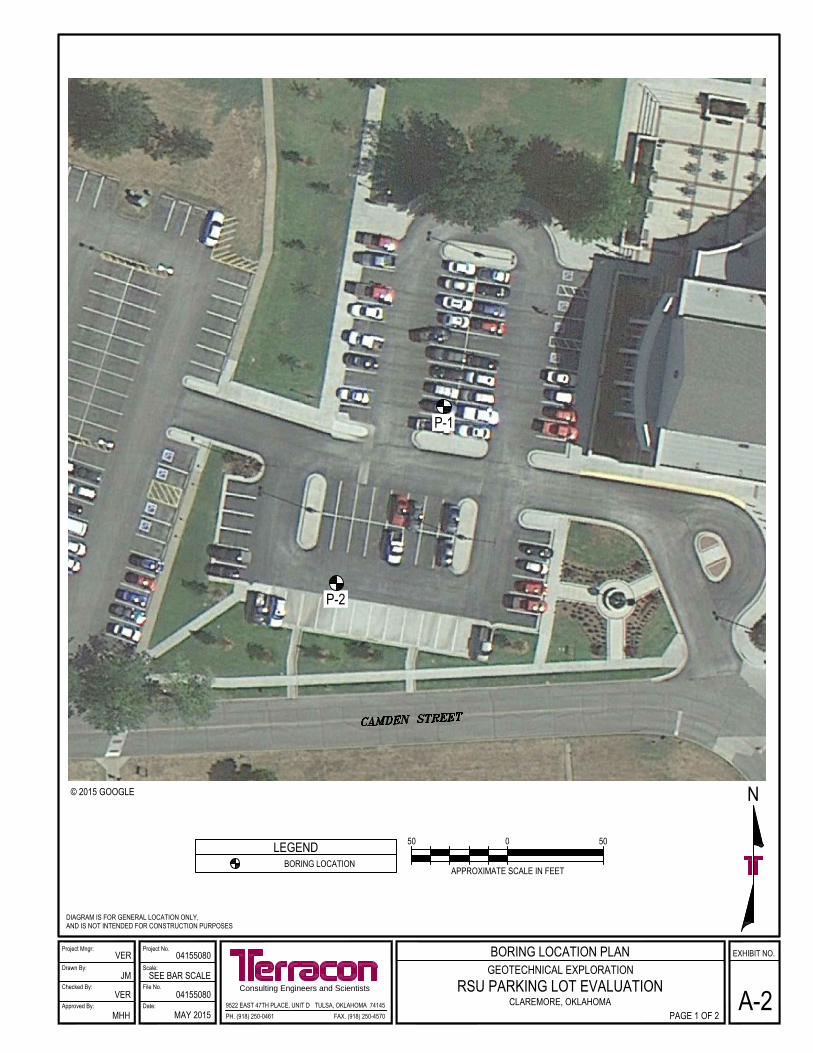
Site layout See Appendix A, Exhibit A-2: Boring Location Plan
Proposed development
■ Parking Lot Evaluation: The existing asphalt concrete
pavement will be replaced with a concrete pavement.
■ Physical Plant Additions: we understand that recent earthwork
activities have been performed and that RSU is interested in
updating Terracon Geotechnical Report No. 04135238 dated
January 29, 2014 for the construction of a building and a paved
parking lot.

Geotechnical Engineering Report RSU Parking Lot and Physical Plant Additions ■ Stillwater, Oklahoma May 20, 2015 ■ Terracon Project No. 04155080
Responsive ■ Resourceful ■ Reliable 2
Item Description
Maximum building addition
loads
Columns: 50 kips (assumed)
Walls: 2 kips/ft. (assumed)
Floor slabs: 150 psf uniform (assumed)
Grading
Final grading plans have not been provided at this time. However,
we anticipate that maximum cut and fill depths on the order of 1 to 3
feet, relatively to the existing grades, will be required to develop the
final building and pavement subgrade elevations.
2.2 Site Location and Description
Item Description
Location
Rogers State University in Claremore, OK. Our geotechnical
services were performed at two locations, as follows:
■ Parking Lot Evaluation: The parking lot is located on the west
side of the RSU Student Services Center.
■ Physical Plant Additions: The site is located on the south side
of the RSU Physical Plant, near the intersection of W Blue
Starr Drive (County Road E 480) and Holly Creek Road.
Existing improvements
■ Parking Lot Evaluation: Asphalt parking lot.
■ Physical Plant Additions: Small metal buildings, paved and
gravel parking and drive areas.
Existing topography Relatively level
SUBSURFACE CONDITIONS 3.0
3.1 Typical Profile
Based on the results of the borings, subsurface conditions on the project site consisted of lean
clay fill soils to depths of 5 to 6.5 feet in the Physical Plant Addition area and to a depth of 2 feet
in the Parking Lot area. Beneath the fill soils we encountered medium stiff to very stiff lean clay
and shaley lean clay soils to boring termination depths of approximately 5 to 15 feet. The upper
soils consist of relatively low plasticity clays. We have been told that the existing fill soils were
removed and recompacted since our original report. The soil samples tested had the following
measured liquid limits, plastic limits, and plasticity indices:
Sample Location, Depth Liquid Limit, (%) Plastic Limit, (%) Plasticity Index, (%)
Boring B-1, 0.5 – 2.0 ft. 32 18 14
Boring B-3, 2.0 – 3.5 ft. 32 20 12

Geotechnical Engineering Report RSU Parking Lot and Physical Plant Additions ■ Stillwater, Oklahoma May 20, 2015 ■ Terracon Project No. 04155080
Responsive ■ Resourceful ■ Reliable 3
Sample Location, Depth Liquid Limit, (%) Plastic Limit, (%) Plasticity Index, (%)
Boring P-2, 1.0 – 2.5 ft. 33 17 16
Boring P-2, 1.0 – 2.5 ft. 30 18 12
Conditions encountered at each boring location are indicated on the individual boring logs included
in Appendix A. Stratification boundaries on the boring logs represent the approximate location of
changes in soil types; in-situ, the transition between materials may be gradual.
3.2 Groundwater
The boreholes were observed while drilling and immediately after completion for the presence
and level of groundwater. No groundwater was observed at these times. Longer monitoring in
piezometers or cased holes, sealed from the influence of surface water, would be required to
evaluate longer-term groundwater conditions. During some periods of the year, perched water
could be present. Fluctuations in groundwater levels should be expected throughout the year
depending upon variations in the amount of rainfall, runoff, evaporation, and other hydrological
factors not apparent at the time the borings were performed.
RECOMMENDATIONS FOR DESIGN AND CONSTRUCTION 4.0
4.1 Geotechnical Considerations
We encountered existing fill materials to depths of about 5 to 6.5 feet at borings B-1 to B-3,
which were drilled for the proposed physical plant additions. We have been told that these soils
were removed and recompacted since our original report. We were told that observation and
testing was not performed to evaluate the quality of fill construction. The soils encountered at
the boring locations appear to consist of suitable material types for construction.
Because of the potential for variation in the composition and quality of existing fill away from the
borings, there is an inherent risk of unpredictable settlement of floor slabs, footings, and
pavements constructed over existing fills. This risk cannot be eliminated unless the full-depth of
the existing fill is removed and replaced with tested and approved, new engineered fill.
However, the risk can be reduced with thorough observation and testing by a representative of
the geotechnical engineer during construction. Close observation and testing will be required
during construction to evaluate the presence and extent of unsuitable fill materials and verify
that the proposed structure is supported by suitable materials. Any unsuitable fill materials will
require removal and replacement with engineered fill.

Geotechnical Engineering Report RSU Parking Lot and Physical Plant Additions ■ Stillwater, Oklahoma May 20, 2015 ■ Terracon Project No. 04155080
Responsive ■ Resourceful ■ Reliable 4
The proposed building can be supported on shallow foundations bearing in properly constructed
new engineered fill or further verified existing fill. Recommendations and design parameters for
shallow foundations are presented in section 4.3 Foundations.
Recommendations regarding earthwork, design and construction of foundations, and support of
floor slabs and pavements are presented below.
4.2 Earthwork
Site Preparation 4.2.1
Areas within the limits of construction should be stripped and cleared of all surface vegetation,
topsoil, loose material, and debris. After stripping and completing any required cuts and
overexcavations, the subgrade should be proofrolled to aid in locating soft and unstable areas.
Proofrolling should be performed with a loaded tandem axle dump truck weighing at least 25
tons. Areas too small to proofroll should be evaluated by the geotechnical engineer. Soft,
unstable soil should be removed and replaced with tested and approved, engineered fill, if they
cannot be adequately stabilized in-place.
After completing the proofrolling, and before placing any fill, the exposed subgrade should be
scarified to a minimum depth of 9 inches, moisture conditioned, and compacted as
recommended in section 4.2.3 Compaction Requirements.
Fill Material Types 4.2.2
Engineered fill should meet the following material property requirements:
Fill Type 1 USCS Classification Acceptable Location for Placement
Low Volume
Change (LVC)
Material 2
CL or SC with
PI ≤ 18 All locations and elevations
On-Site Clay Soils CL All locations and elevations
1. Controlled, compacted fill should consist of approved materials that are free of organic matter and
debris and contain maximum rock size of 3 inches. Frozen material should not be used, and fill
should not be placed on a frozen subgrade. A sample of each material type should be submitted to
the geotechnical engineer for evaluation.
2. Low plasticity cohesive soil having a plasticity index (PI) of 18 or less and containing at least 15%
fines (material passing the No. 200 sieve, based on dry weight).

Geotechnical Engineering Report RSU Parking Lot and Physical Plant Additions ■ Stillwater, Oklahoma May 20, 2015 ■ Terracon Project No. 04155080
Responsive ■ Resourceful ■ Reliable 5
Compaction Requirements 4.2.3
The scarified and compacted subgrade and fill should be moisture conditioned and compacted
using recommendations in the following table:
Item Description
Subgrade Scarification Depth 9 inches
Fill Lift Thickness 9-inches or less in loose thickness
Compaction Requirements 1
At least 95% of the material’s maximum standard Proctor
dry density (ASTM D-698)
Moisture Content -1 to +3% of the optimum moisture content
1. We recommend that engineered fills (including scarified and compacted subgrade) be tested
for moisture content and compaction. Should the results of the in-place density tests indicate
the specified moisture or compaction limits have not been met, the area represented by the
test should be reworked and retested as required until the specified moisture and compaction
requirements are achieved.
The recommended moisture content should be maintained in the scarified and compacted
subgrade and new fills, until fills are completed and on-grade floor slabs and pavements are
constructed.
Utility Trench Backfill 4.2.4
Utility trenches are a common source of water infiltration and migration. All utility trenches that
penetrate beneath the building should be effectively sealed to restrict water intrusion and flow
through the trenches that could migrate below the building. We recommend constructing an
effective clay “trench plug” that extends at least 5 feet out from the face of the building exterior.
The plug material should consist of clay compacted at a water content at or above the soils
optimum water content. The clay fill should be placed to completely surround the utility line and be
compacted in accordance with recommendations in this report.
Grading and Drainage 4.2.5
All grades must provide effective drainage away from the building during and after construction.
Water permitted to pond next to the building can result in greater soil movements than those
discussed in this report. These greater movements can result in unacceptable differential floor
slab movements, cracked slabs and walls, and roof leaks. Estimated movements described in
this report are based on effective drainage for the life of the structure and cannot be relied upon
if effective drainage is not maintained.
Exposed ground should be sloped at a minimum 5 percent away from the building for at least 10
feet beyond the perimeter of the building. After building construction and landscaping, we
recommend verifying final grades to document that effective drainage has been achieved.
Geotechnical Engineering Report RSU Parking Lot and Physical Plant Additions ■ Stillwater, Oklahoma May 20, 2015 ■ Terracon Project No. 04155080
Responsive ■ Resourceful ■ Reliable 6
Grades around the structure should also be periodically inspected and adjusted as necessary,
as part of the structure’s maintenance program.
Planters located within 10 feet of the structures should be self-contained to prevent water
accessing the building subgrade soils. Sprinkler mains and spray heads should be located a
minimum of 5 feet away from the building lines. Low-volume, drip style landscaped irrigation
should not be used near the building. Roof runoff should be collected in drains or gutters. Roof
drains and downspouts should be discharged onto pavements which slope away from the
building or down spouts should be extended a minimum of 10 feet away from structures.
Earthwork Construction Considerations 4.2.6
Upon completion of filling and grading, care should be taken to maintain the recommended
subgrade moisture content prior to construction of floor slabs and pavements. Construction
traffic over the completed subgrade should be avoided to the extent practical. The site should
also be graded to prevent ponding of surface water on the prepared subgrades or in
excavations. If the subgrade should become frozen, excessively wetted or dried, or disturbed,
the affected material should be removed or these materials should be scarified, moisture
conditioned, and recompacted prior to floor slab and pavement construction.
Temporary excavations may be required during grading operations. The grading contractor, by
his contract, is usually responsible for designing and constructing stable, temporary excavations
and should shore, slope or bench the sides of the excavations as required, to maintain stability
of both the excavation sides and bottom. All excavations should comply with applicable local,
state and federal safety regulations, including the current OSHA Excavation and Trench Safety
Standards.
Terracon should be retained during the construction phase of the project to provide observation
and testing during earthwork.
4.3 Foundations
Footing Foundation Design Recommendations 4.3.1
Description Design Parameters
Net allowable bearing pressure 1 2,000 psf
Bearing material Newly placed engineered fill or further verified
existing fill
Minimum width Columns: 30 inches
Walls: 16 inches
Minimum depth (below lowest finished exterior
grade) 2
24 inches
Estimated total settlement ¾ inch

Geotechnical Engineering Report RSU Parking Lot and Physical Plant Additions ■ Stillwater, Oklahoma May 20, 2015 ■ Terracon Project No. 04155080
Responsive ■ Resourceful ■ Reliable 7
Description Design Parameters
Estimated differential settlement Less than ¾ inch
Allowable passive pressure (rectangular
pressure distribution) 3
750 psf
Coefficient of sliding friction 4
0.30
1. The recommended allowable bearing pressure is based on foundations bearing on newly
placed engineered fill or further verified existing fill. The net allowable bearing pressure is
the pressure in excess of the minimum surrounding overburden pressure at the footing base
elevation.
2. Minimum depth applies to both perimeter footings and foundations in unheated areas.
3. Allowable passive pressure value considers a factor of safety of about 2. Passive pressure
value applies to undisturbed very stiff, native clay soils, and tested and approved new
engineered fill. Passive resistance should be neglected for the upper 2 feet of the soil below
the final adjacent grade due to strength loss from freeze-thaw and moisture changes.
4. Coefficient of friction value is an ultimate value and does not contain a factor of safety.
Construction Considerations for Footings 4.3.2
The bottom of the footing overexcavations should be free of loose and disturbed material,
debris, and water when backfill is placed. The foundation bearing surface should be free of
loose and disturbed material, debris, and water when concrete is placed. Concrete should be
placed as soon as possible after excavation is completed to reduce the potential for wetting,
drying, or disturbance of the bearing materials. It is recommended that the geotechnical
engineer be retained to observe and test the soil foundation bearing materials.
If unsuitable bearing soils are encountered in footing excavations, the excavations should be
extended deeper to suitable soils and the footings could bear directly on these soils at the lower
level or on lean concrete backfill placed in the excavations as shown in Figure 1 below. The
footings could also bear on properly compacted engineered fill extending down to the suitable
soils. Overexcavation for compacted backfill placement below footings should extend laterally
beyond all edges of the footings at least 8 inches per foot of overexcavation depth below footing
base elevation. The overexcavation should then be backfilled up to the footing base elevation
with approved engineered fill material. The overexcavation and backfill procedure is shown in
Figure 2 below.

Geotechnical Engineering Report RSU Parking Lot and Physical Plant Additions ■ Stillwater, Oklahoma May 20, 2015 ■ Terracon Project No. 04155080
Responsive ■ Resourceful ■ Reliable 8
Figure 1 Figure 2
4.4 Floor Slabs
Floor Slab Design Recommendations 4.4.1
We recommend construction of at least 12 inches of low volume change engineered fill beneath
the floor slab of the building. The recommended fill material type and compaction requirements
are presented in sections 4.2.2 Fill Material Types and 4.2.3 Compaction Requirements.
Based on preparing the floor slab subgrade and constructing engineered fills beneath the floor
slab as recommended, the floor slab should be adequately supported.
The use of a vapor retarder should be considered beneath concrete slabs on grade that will be
covered with wood, tile, carpet or other moisture sensitive or impervious coverings, or when the
slab will support equipment sensitive to moisture. When conditions warrant the use of a vapor
retarder, the slab designer should refer to ACI 302 and/or ACI 360 for procedures and cautions
regarding the use and placement of a vapor retarder.
Floor Slab Construction Considerations 4.4.2
Upon completion of grading operations in the building area, care should be taken to maintain
the recommended subgrade moisture content and density prior to construction of the building
floor slab. If the subgrade should become excessively wetted or dried, or otherwise disturbed
prior to construction of the floor slab, the affected material should be removed or the materials
scarified, moisture conditioned, and recompacted.
4.5 Pavements
Typical Pavement Sections 4.5.1
It has been our experience that soft, wet soils are often encountered beneath existing
pavements. The contractor should anticipate encountering soft, wet soils as they remove the
Geotechnical Engineering Report RSU Parking Lot and Physical Plant Additions ■ Stillwater, Oklahoma May 20, 2015 ■ Terracon Project No. 04155080
Responsive ■ Resourceful ■ Reliable 9
existing pavements at borings P-1 and P-2. We recommend that subgrade improvement be
accomplished by constructing a minimum 10-inch thick layer of select fill beneath the pavement
section. Some on-site subgrade soils may require overexcavation to construct the 10-inch thick
layer of select fill below the pavement section. The select fill should meet the criteria for Low
Volume Change (LVC) material stated in section 4.2.2 Material Types. The 10-inch select fill
layer beneath the pavements should have a Unified Soil Classification System group symbol of
CL or SC. Soils classifying as ML, CL-ML, SM, or SC-SM per the Unified Soil Classification
System should not be used as select fill. An approved crushed aggregate base, crushed
limestone screenings, or broken shale may be considered as an alternative to the select fill
material and, if used, may warrant a slight reduction in the thickness of select fill required.
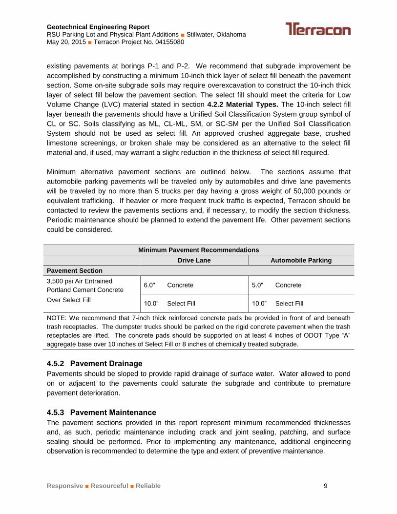
Minimum alternative pavement sections are outlined below. The sections assume that
automobile parking pavements will be traveled only by automobiles and drive lane pavements
will be traveled by no more than 5 trucks per day having a gross weight of 50,000 pounds or
equivalent trafficking. If heavier or more frequent truck traffic is expected, Terracon should be
contacted to review the pavements sections and, if necessary, to modify the section thickness.
Periodic maintenance should be planned to extend the pavement life. Other pavement sections
could be considered.
Minimum Pavement Recommendations
Drive Lane Automobile Parking
Pavement Section
3,500 psi Air Entrained
Portland Cement Concrete
Over Select Fill
6.0" Concrete 5.0" Concrete
10.0” Select Fill 10.0” Select Fill
NOTE: We recommend that 7-inch thick reinforced concrete pads be provided in front of and beneath
trash receptacles. The dumpster trucks should be parked on the rigid concrete pavement when the trash
receptacles are lifted. The concrete pads should be supported on at least 4 inches of ODOT Type “A”
aggregate base over 10 inches of Select Fill or 8 inches of chemically treated subgrade.
Pavement Drainage 4.5.2
Pavements should be sloped to provide rapid drainage of surface water. Water allowed to pond
on or adjacent to the pavements could saturate the subgrade and contribute to premature
pavement deterioration.
Pavement Maintenance 4.5.3
The pavement sections provided in this report represent minimum recommended thicknesses
and, as such, periodic maintenance including crack and joint sealing, patching, and surface
sealing should be performed. Prior to implementing any maintenance, additional engineering
observation is recommended to determine the type and extent of preventive maintenance.
Geotechnical Engineering Report RSU Parking Lot and Physical Plant Additions ■ Stillwater, Oklahoma May 20, 2015 ■ Terracon Project No. 04155080
Responsive ■ Resourceful ■ Reliable 10
GENERAL COMMENTS 5.0
Terracon should be retained to review the final design plans and specifications so comments
can be made regarding interpretation and implementation of our geotechnical recommendations
in the design and specifications. Terracon also should be retained to provide observation and
testing services during grading, excavation, foundation construction and other earth-related
construction phases of the project.
The analysis and recommendations presented in this report are based upon the data obtained
from the borings performed at the indicated locations and from other information discussed in
this report. This report does not reflect variations that may occur between borings, across the
site, or due to the modifying effects of construction or weather. The nature and extent of such
variations may not become evident until during or after construction. If variations appear, we
should be immediately notified so that further evaluation and supplemental recommendations
can be provided.
The scope of services for this project does not include either specifically or by implication any
environmental or biological (e.g., mold, fungi, bacteria) assessment of the site or identification or
prevention of pollutants, hazardous materials or conditions. If the owner is concerned about the
potential for such contamination or pollution, other studies should be undertaken.
This report has been prepared for the exclusive use of our client for specific application to the
project discussed and has been prepared in accordance with generally accepted geotechnical
engineering practices. No warranties, either express or implied, are intended or made. Site
safety, excavation support, and dewatering requirements are the responsibility of others. In the
event that changes in the nature, design, or location of the project as outlined in this report are
planned, the conclusions and recommendations contained in this report shall not be considered
valid unless Terracon reviews the changes and either verifies or modifies the conclusions of this
report in writing.

APPENDIX A
FIELD EXPLORATION

Project Mngr:
Approved By:
Checked By:
Drawn By:
Project No.
Scale:
Date:
File No.Consulting Engineers and Scientists
EXHIBIT NO.
9522 EAST 47TH PLACE, UNIT D TULSA, OKLAHOMA 74145FAX. (918) 250-4570PH. (918) 250-0461
VER
JM
VER
MHH
04155080
SEE BAR SCALE
04155080
MAY 2015
SITE LOCATION MAP
A-1GEOTECHNICAL EXPLORATION
PARKING LOT EVALUATIONCLAREMORE, OKLAHOMA
N
APPROXIMATE SCALE IN FEET
1500 0 1000 1500500
© 2015 GOOGLE
PHYSICAL PLANTSITE LOCATION
PARKING LOTSITE LOCATION
Project Mngr:
Approved By:
Checked By:
Drawn By:
Project No.
Scale:
Date:
File No.Consulting Engineers and Scientists
EXHIBIT NO.
9522 EAST 47TH PLACE, UNIT D TULSA, OKLAHOMA 74145FAX. (918) 250-4570PH. (918) 250-0461
VER
JM
VER
MHH
04155080
SEE BAR SCALE
04155080
MAY 2015
BORING LOCATION PLAN
A-2GEOTECHNICAL EXPLORATION
RSU PARKING LOT EVALUATIONCLAREMORE, OKLAHOMA
PAGE 1 OF 2
N
LEGENDBORING LOCATION
DIAGRAM IS FOR GENERAL LOCATION ONLY, AND IS NOT INTENDED FOR CONSTRUCTION PURPOSES
© 2015 GOOGLE
APPROXIMATE SCALE IN FEET
0 5050
P-1
P-2

Project Mngr:
Approved By:
Checked By:
Drawn By:
Project No.
Scale:
Date:
File No.Consulting Engineers and Scientists
EXHIBIT NO.
9522 EAST 47TH PLACE, UNIT D TULSA, OKLAHOMA 74145FAX. (918) 250-4570PH. (918) 250-0461
VER
JM
VER
MHH
04155080
SEE BAR SCALE
04155080
MAY 2015
BORING LOCATION PLAN
A-2GEOTECHNICAL EXPLORATION
RSU PHYSICAL PLANT ADDITIONSCLAREMORE, OKLAHOMA
PAGE 2 OF 2
N
LEGENDBORING LOCATION
DIAGRAM IS FOR GENERAL LOCATION ONLY, AND IS NOT INTENDED FOR CONSTRUCTION PURPOSES
© 2015 GOOGLE
APPROXIMATE SCALE IN FEET
0 5050
B-1B-2B-3
BENCHMARK: FINISH FLOOR OF EXISTING BUILDING AT DOORWAY. ELEVATION 100 FEET

Geotechnical Engineering Report RSU Parking Lot and Physical Plant Additions ■ Stillwater, Oklahoma May 20, 2015 ■ Terracon Project No. 04155080
Reliable ■ Resourceful ■ Responsive Exhibit A-3
Field Exploration Description
The boring locations were established in the field by Terracon personnel by taping from existing
reference features. Terracon determined the approximate ground surface elevations at borings
B-1 to B-3 using an engineer’s level. The finish floor of the existing building immediately north
of the borehole locations was used as a benchmark. The approximate ground surface
elevations at the borings are shown on the logs based on an elevation of 100.0 feet for the
benchmark. The elevations shown on the logs have been rounded to the nearest 0.5 feet. The
boring locations and elevations should be considered accurate only to the degree implied by the
methods used to define them. We did not collect elevation data at borings P-1 and P-2.
We drilled the borings with an ATV-mounted rotary drill rig using continuous flight solid-stem
augers to advance the boreholes. Representative samples were obtained by the split-barrel
sampling procedure. The split-barrel sampling procedure uses a standard 2-inch, O.D. split-
barrel sampling spoon that is driven into the bottom of the boring with a 140-pound drive
hammer falling 30 inches. The number of blows required to advance the sampling spoon the
last 12 inches, or less, of an 18-inch sampling interval or portion thereof, is recorded as the
standard penetration resistance value, N. The N value is used to estimate the in-situ relative
density of granular soils and, to a lesser degree of accuracy, the consistency of cohesive soils
and the hardness of bedrock.
The sampling depths, penetration distances, and N values are reported on the boring logs. The
samples were tagged for identification, sealed to reduce moisture loss and returned to the
laboratory for further examination, testing and classification.
An automatic SPT hammer was used to advance the split-barrel sampler in the borings performed
on this site. Generally, a greater efficiency is achieved with the automatic hammer compared to
the conventional safety hammer operated with a cathead and rope. The effect of the automatic
hammer's efficiency has been considered in the interpretation and analysis of the subsurface
information for this report.
A field log of each boring was prepared by the drill crew. These logs included visual
classifications of the materials encountered during drilling as well as the driller’s interpretation of
the subsurface conditions between samples. Final boring logs included with this report
represent the engineer's interpretation of the field logs and include modifications based on
laboratory observation and tests of the samples.

5.0
13.5
15.0
6" Crushed RockFILL - LEAN CLAY , with sand, brown and gray
LEAN CLAY (CL), gray and reddish-brown, stiff
SHALEY LEAN CLAY (CL), olive-gray, very stiff
Boring Terminated at 15 Feet
3-5-9N=14
3-4-5N=9
3-3-5N=8
2-3-5N=8
14-27-42N=69
15
17
26
19
16
32-18-14
94.5
86
84.5
18
14
12
10
18
Hammer Type: Automatic+Classification estimated from disturbed samples. Coresamples and petrographic analysis may reveal other rock types.
Stratification lines are approximate. In-situ, the transition may be gradual.
LOCATION
DEPTH
Latitude: 36.32099° Longitude: -95.64149°
GR
AP
HIC
LO
G See Exhibit A-2
TH
IS B
OR
ING
LO
G IS
NO
T V
ALI
D IF
SE
PA
RA
TE
D F
RO
M O
RIG
INA
L R
EP
OR
T.
G
EO
SM
AR
T L
OG
-NO
WE
LL 0
415
508
0.G
PJ
Claremore, OklahomaSITE:
Page 1 of 1
Advancement Method:Power Auger
Abandonment Method:
9522 East 47th Place, Unit DTulsa, Oklahoma
Notes:
Project No.: 04155080
Drill Rig: ATV 380E
Boring Started: 5/12/2015
BORING LOG NO. B-1Rogers State UniversityCLIENT:
Driller: TS
Boring Completed: 5/12/2015
Exhibit: A-4
See Exhibit A-3 for description of fieldprocedures.See Appendix B for description of laboratoryprocedures and additional data (if any).
See Appendix C for explanation of symbols andabbreviations.
PROJECT: Parking Lot Evaluation & Physical PlantAdditions
FIE
LD T
ES
TR
ES
ULT
S
PE
RC
EN
T F
INE
S
WA
TE
RC
ON
TE
NT
(%
)
ATTERBERGLIMITS
LL-PL-PISurface Elev.: 99.5 (Ft.)
ELEVATION (Ft.)
SA
MP
LE T
YP
E
WA
TE
R L
EV
EL
OB
SE
RV
AT
ION
S
DE
PT
H (
Ft.)
5
10
15
RE
CO
VE
RY
(In
.)
UN
CO
NF
INE
DC
OM
PR
ES
SIV
ES
TR
EN
GT
H (
psi)
WATER LEVEL OBSERVATIONS
12 ft After Boring
12 ft While Drilling
6.5
13.5
15.0
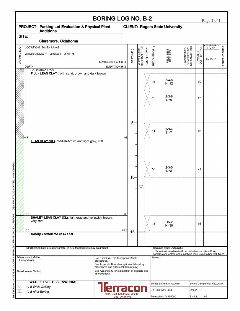
6" Crushed RockFILL - LEAN CLAY , with sand, brown and dark brown
LEAN CLAY (CL), reddish-brown and light gray, stiff
SHALEY LEAN CLAY (CL), light gray and yellowish-brown,very stiff
Boring Terminated at 15 Feet
3-4-8N=12
2-3-6N=9
2-3-4N=7
2-3-5N=8
9-15-23N=38
10
13
16
21
16
93
86
84.5
16
12
14
18
18
Hammer Type: Automatic+Classification estimated from disturbed samples. Coresamples and petrographic analysis may reveal other rock types.
Stratification lines are approximate. In-situ, the transition may be gradual.
LOCATION
DEPTH
Latitude: 36.32097° Longitude: -95.64175°
GR
AP
HIC
LO
G See Exhibit A-2
TH
IS B
OR
ING
LO
G IS
NO
T V
ALI
D IF
SE
PA
RA
TE
D F
RO
M O
RIG
INA
L R
EP
OR
T.
G
EO
SM
AR
T L
OG
-NO
WE
LL 0
415
508
0.G
PJ
Claremore, OklahomaSITE:
Page 1 of 1
Advancement Method:Power Auger
Abandonment Method:
9522 East 47th Place, Unit DTulsa, Oklahoma
Notes:
Project No.: 04155080
Drill Rig: ATV 380E
Boring Started: 5/12/2015
BORING LOG NO. B-2Rogers State UniversityCLIENT:
Driller: TS
Boring Completed: 5/12/2015
Exhibit: A-5
See Exhibit A-3 for description of fieldprocedures.See Appendix B for description of laboratoryprocedures and additional data (if any).
See Appendix C for explanation of symbols andabbreviations.
PROJECT: Parking Lot Evaluation & Physical PlantAdditions
FIE
LD T
ES
TR
ES
ULT
S
PE
RC
EN
T F
INE
S
WA
TE
RC
ON
TE
NT
(%
)
ATTERBERGLIMITS
LL-PL-PISurface Elev.: 99.5 (Ft.)
ELEVATION (Ft.)
SA
MP
LE T
YP
E
WA
TE
R L
EV
EL
OB
SE
RV
AT
ION
S
DE
PT
H (
Ft.)
5
10
15
RE
CO
VE
RY
(In
.)
UN
CO
NF
INE
DC
OM
PR
ES
SIV
ES
TR
EN
GT
H (
psi)
WATER LEVEL OBSERVATIONS
11 ft After Boring
11 ft While Drilling

5.0
13.0
15.0
6" Crushed RockFILL - LEAN CLAY , with sand, brown, dark brown and gray
- with gravel below 2 feet
LEAN CLAY (CL), with sand, gray and reddish-brown, stiff
SHALEY LEAN CLAY (CL), olive-gray, very stiff
Boring Terminated at 15 Feet
3-3-3N=6
26-18-9N=27
3-4-7N=11
2-4-4N=8
8-14-25N=39
13
15
16
20
19
32-20-12
94
86
84
12
14
18
18
18
Hammer Type: Automatic+Classification estimated from disturbed samples. Coresamples and petrographic analysis may reveal other rock types.
Stratification lines are approximate. In-situ, the transition may be gradual.
LOCATION
DEPTH
Latitude: 36.32097° Longitude: -95.64198°
GR
AP
HIC
LO
G See Exhibit A-2
TH
IS B
OR
ING
LO
G IS
NO
T V
ALI
D IF
SE
PA
RA
TE
D F
RO
M O
RIG
INA
L R
EP
OR
T.
G
EO
SM
AR
T L
OG
-NO
WE
LL 0
415
508
0.G
PJ
Claremore, OklahomaSITE:
Page 1 of 1
Advancement Method:Power Auger
Abandonment Method:
9522 East 47th Place, Unit DTulsa, Oklahoma
Notes:
Project No.: 04155080
Drill Rig: ATV 380E
Boring Started: 5/12/2015
BORING LOG NO. B-3Rogers State UniversityCLIENT:
Driller: TS
Boring Completed: 5/12/2015
Exhibit: A-6
See Exhibit A-3 for description of fieldprocedures.See Appendix B for description of laboratoryprocedures and additional data (if any).
See Appendix C for explanation of symbols andabbreviations.
PROJECT: Parking Lot Evaluation & Physical PlantAdditions
FIE
LD T
ES
TR
ES
ULT
S
PE
RC
EN
T F
INE
S
WA
TE
RC
ON
TE
NT
(%
)
ATTERBERGLIMITS
LL-PL-PISurface Elev.: 99 (Ft.)
ELEVATION (Ft.)
SA
MP
LE T
YP
E
WA
TE
R L
EV
EL
OB
SE
RV
AT
ION
S
DE
PT
H (
Ft.)
5
10
15
RE
CO
VE
RY
(In
.)
UN
CO
NF
INE
DC
OM
PR
ES
SIV
ES
TR
EN
GT
H (
psi)
WATER LEVEL OBSERVATIONS
11 ft After Boring
11 ft While Drilling
2.5
5.0
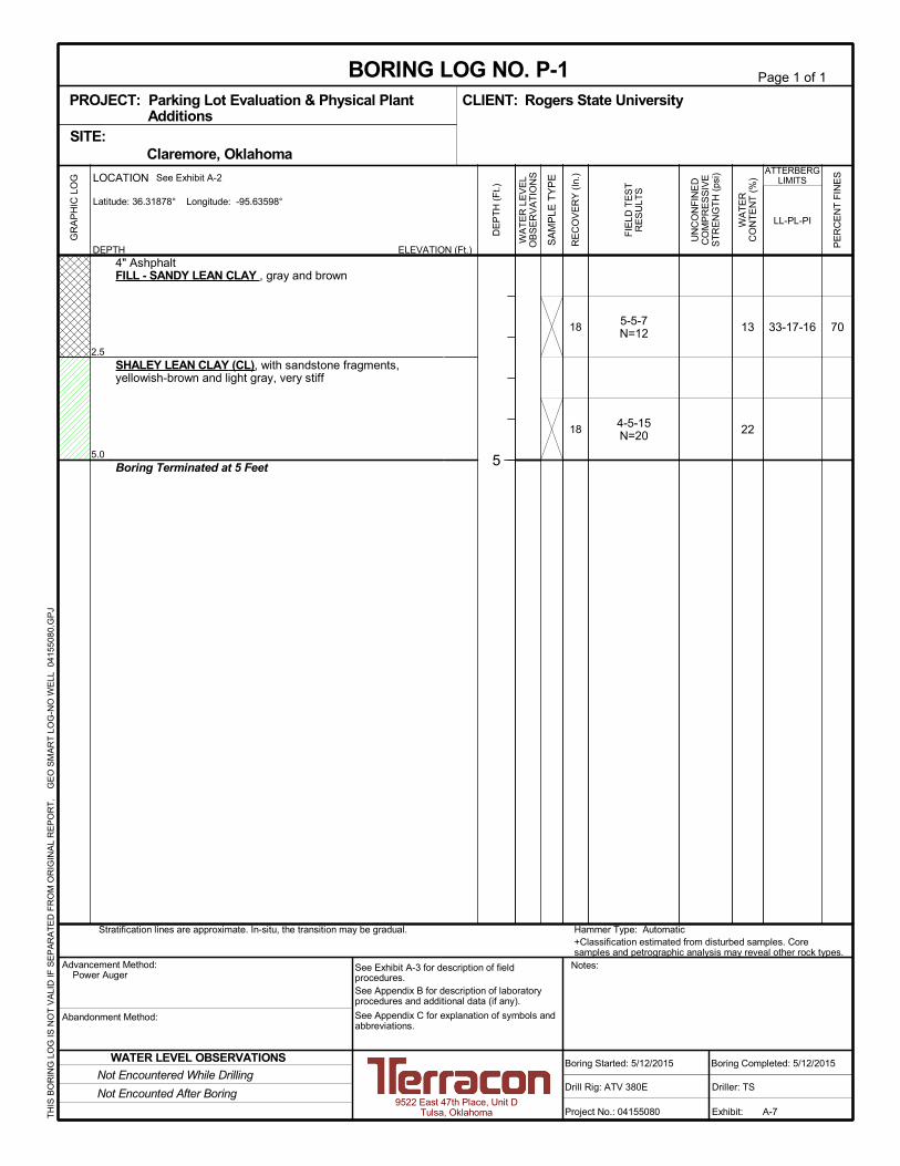
4" AshphaltFILL - SANDY LEAN CLAY , gray and brown
SHALEY LEAN CLAY (CL), with sandstone fragments,yellowish-brown and light gray, very stiff
Boring Terminated at 5 Feet
5-5-7N=12
4-5-15N=20
7013
22
33-17-1618
18
Hammer Type: Automatic+Classification estimated from disturbed samples. Coresamples and petrographic analysis may reveal other rock types.
Stratification lines are approximate. In-situ, the transition may be gradual.
LOCATION
DEPTH
Latitude: 36.31878° Longitude: -95.63598°
GR
AP
HIC
LO
G See Exhibit A-2
TH
IS B
OR
ING
LO
G IS
NO
T V
ALI
D IF
SE
PA
RA
TE
D F
RO
M O
RIG
INA
L R
EP
OR
T.
G
EO
SM
AR
T L
OG
-NO
WE
LL 0
415
508
0.G
PJ
Claremore, OklahomaSITE:
Page 1 of 1
Advancement Method:Power Auger
Abandonment Method:
9522 East 47th Place, Unit DTulsa, Oklahoma
Notes:
Project No.: 04155080
Drill Rig: ATV 380E
Boring Started: 5/12/2015
BORING LOG NO. P-1Rogers State UniversityCLIENT:
Driller: TS
Boring Completed: 5/12/2015
Exhibit: A-7
See Exhibit A-3 for description of fieldprocedures.See Appendix B for description of laboratoryprocedures and additional data (if any).
See Appendix C for explanation of symbols andabbreviations.
PROJECT: Parking Lot Evaluation & Physical PlantAdditions
FIE
LD T
ES
TR
ES
ULT
S
PE
RC
EN
T F
INE
S
WA
TE
RC
ON
TE
NT
(%
)
ATTERBERGLIMITS
LL-PL-PI
ELEVATION (Ft.)
SA
MP
LE T
YP
E
WA
TE
R L
EV
EL
OB
SE
RV
AT
ION
S
DE
PT
H (
Ft.)
5
RE
CO
VE
RY
(In
.)
UN
CO
NF
INE
DC
OM
PR
ES
SIV
ES
TR
EN
GT
H (
psi)
WATER LEVEL OBSERVATIONS
Not Encounted After Boring
Not Encountered While Drilling
2.5
5.0
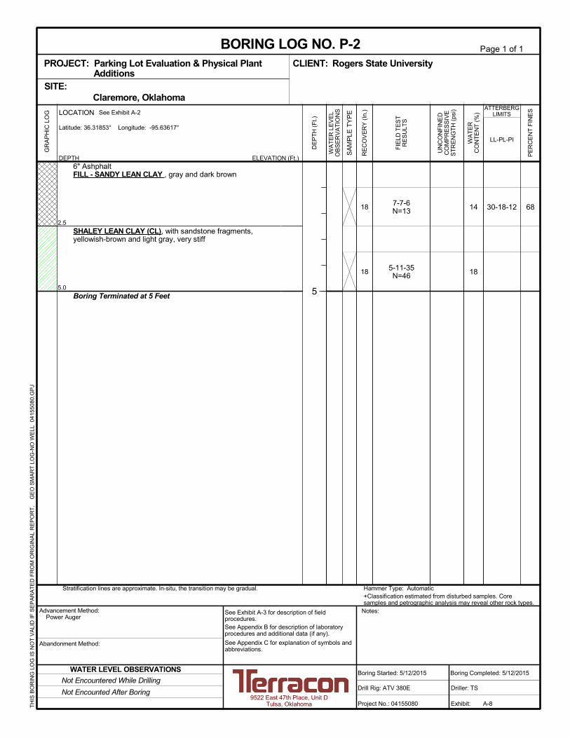
6" AshphaltFILL - SANDY LEAN CLAY , gray and dark brown
SHALEY LEAN CLAY (CL), with sandstone fragments,yellowish-brown and light gray, very stiff
Boring Terminated at 5 Feet
7-7-6N=13
5-11-35N=46
6814
18
30-18-1218
18
Hammer Type: Automatic+Classification estimated from disturbed samples. Coresamples and petrographic analysis may reveal other rock types.
Stratification lines are approximate. In-situ, the transition may be gradual.
LOCATION
DEPTH
Latitude: 36.31853° Longitude: -95.63617°
GR
AP
HIC
LO
G See Exhibit A-2
TH
IS B
OR
ING
LO
G IS
NO
T V
ALI
D IF
SE
PA
RA
TE
D F
RO
M O
RIG
INA
L R
EP
OR
T.
G
EO
SM
AR
T L
OG
-NO
WE
LL 0
415
508
0.G
PJ
Claremore, OklahomaSITE:
Page 1 of 1
Advancement Method:Power Auger
Abandonment Method:
9522 East 47th Place, Unit DTulsa, Oklahoma
Notes:
Project No.: 04155080
Drill Rig: ATV 380E
Boring Started: 5/12/2015
BORING LOG NO. P-2Rogers State UniversityCLIENT:
Driller: TS
Boring Completed: 5/12/2015
Exhibit: A-8
See Exhibit A-3 for description of fieldprocedures.See Appendix B for description of laboratoryprocedures and additional data (if any).
See Appendix C for explanation of symbols andabbreviations.
PROJECT: Parking Lot Evaluation & Physical PlantAdditions
FIE
LD T
ES
TR
ES
ULT
S
PE
RC
EN
T F
INE
S
WA
TE
RC
ON
TE
NT
(%
)
ATTERBERGLIMITS
LL-PL-PI
ELEVATION (Ft.)
SA
MP
LE T
YP
E
WA
TE
R L
EV
EL
OB
SE
RV
AT
ION
S
DE
PT
H (
Ft.)
5
RE
CO
VE
RY
(In
.)
UN
CO
NF
INE
DC
OM
PR
ES
SIV
ES
TR
EN
GT
H (
psi)
WATER LEVEL OBSERVATIONS
Not Encounted After Boring
Not Encountered While Drilling

APPENDIX B
SUPPORTING INFORMATION
Geotechnical Engineering Report RSU Parking Lot and Physical Plant Additions ■ Stillwater, Oklahoma May 20, 2015 ■ Terracon Project No. 04155080
Reliable ■ Resourceful ■ Responsive Exhibit B-1
Laboratory Testing
Samples retrieved during the field exploration were taken to the laboratory for further
observation by the project geotechnical engineer and were classified in accordance with the
Unified Soil Classification System (USCS) described in Appendix A. After the testing was
completed, the field descriptions were confirmed or modified as necessary.
Selected soil and bedrock samples obtained from the site were tested for the following
engineering properties:
Water content
Atterberg limits
Sieve analysis

APPENDIX C
SUPPORTING DOCUMENTS
TraceWithModifier
Water Level Aftera Specified Period of Time
GRAIN SIZE TERMINOLOGYRELATIVE PROPORTIONS OF SAND AND GRAVEL
TraceWithModifier
Standard Penetration orN-Value
Blows/Ft.
Descriptive Term(Consistency)
Loose
Very Stiff
Exhibit C-1
Standard Penetration orN-Value
Blows/Ft.
Ring SamplerBlows/Ft.
Ring SamplerBlows/Ft.
Medium Dense
Dense
Very Dense
0 - 1 < 3
4 - 9 2 - 4 3 - 4
Medium-Stiff 5 - 9
30 - 50
WA
TE
R L
EV
EL
Auger
Shelby Tube
Ring Sampler
Grab Sample
8 - 15
Split Spoon
Macro Core
Rock Core
PLASTICITY DESCRIPTION
Term
< 1515 - 29> 30
Descriptive Term(s)of other constituents
Water InitiallyEncountered
Water Level After aSpecified Period of Time
Major Componentof Sample
Percent ofDry Weight
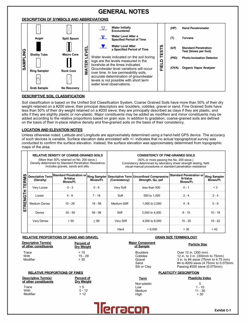
(More than 50% retained on No. 200 sieve.)Density determined by Standard Penetration Resistance
Includes gravels, sands and silts.
Hard
Very Loose 0 - 3 0 - 6 Very Soft
7 - 18 Soft
10 - 29 19 - 58
59 - 98 Stiff
less than 500
500 to 1,000
1,000 to 2,000
2,000 to 4,000
4,000 to 8,000> 99
LOCATION AND ELEVATION NOTES
SA
MP
LIN
G
FIE
LD
TE
ST
S
(HP)
(T)
(b/f)
(PID)
(OVA)
DESCRIPTION OF SYMBOLS AND ABBREVIATIONS
Descriptive Term(Density)
Non-plasticLowMediumHigh
BouldersCobblesGravelSandSilt or Clay
10 - 18
> 50 15 - 30 19 - 42
> 30 > 42
_
Hand Penetrometer
Torvane
Standard PenetrationTest (blows per foot)
Photo-Ionization Detector
Organic Vapor Analyzer
Water levels indicated on the soil boringlogs are the levels measured in theborehole at the times indicated.Groundwater level variations will occurover time. In low permeability soils,accurate determination of groundwaterlevels is not possible with short termwater level observations.
CONSISTENCY OF FINE-GRAINED SOILS
(50% or more passing the No. 200 sieve.)Consistency determined by laboratory shear strength testing, field
visual-manual procedures or standard penetration resistance
DESCRIPTIVE SOIL CLASSIFICATION
> 8,000
Unless otherwise noted, Latitude and Longitude are approximately determined using a hand-held GPS device. The accuracyof such devices is variable. Surface elevation data annotated with +/- indicates that no actual topographical survey wasconducted to confirm the surface elevation. Instead, the surface elevation was approximately determined from topographicmaps of the area.
Soil classification is based on the Unified Soil Classification System. Coarse Grained Soils have more than 50% of their dryweight retained on a #200 sieve; their principal descriptors are: boulders, cobbles, gravel or sand. Fine Grained Soils haveless than 50% of their dry weight retained on a #200 sieve; they are principally described as clays if they are plastic, andsilts if they are slightly plastic or non-plastic. Major constituents may be added as modifiers and minor constituents may beadded according to the relative proportions based on grain size. In addition to gradation, coarse-grained soils are definedon the basis of their in-place relative density and fine-grained soils on the basis of their consistency.
Plasticity Index
01 - 1011 - 30
> 30
RELATIVE PROPORTIONS OF FINES
Descriptive Term(s)of other constituents
Percent ofDry Weight
< 55 - 12> 12
No Recovery
RELATIVE DENSITY OF COARSE-GRAINED SOILS
Particle Size
Over 12 in. (300 mm)12 in. to 3 in. (300mm to 75mm)3 in. to #4 sieve (75mm to 4.75 mm)#4 to #200 sieve (4.75mm to 0.075mmPassing #200 sieve (0.075mm)
ST
RE
NG
TH
TE
RM
S Unconfined CompressiveStrength, Qu, psf
4 - 8
GENERAL NOTES
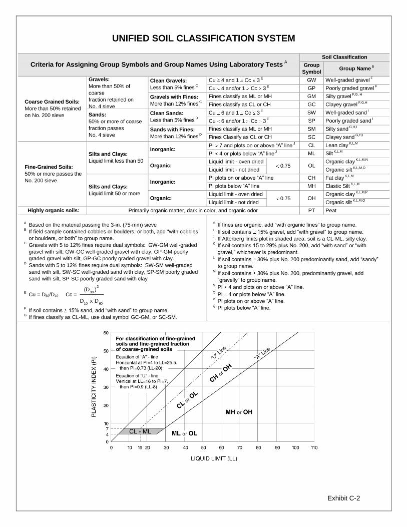
Exhibit C-2
UNIFIED SOIL CLASSIFICATION SYSTEM
Criteria for Assigning Group Symbols and Group Names Using Laboratory Tests A
Soil Classification
Group
Symbol Group Name
B
Coarse Grained Soils:
More than 50% retained
on No. 200 sieve
Gravels:
More than 50% of
coarse
fraction retained on
No. 4 sieve
Clean Gravels:
Less than 5% fines C
Cu 4 and 1 Cc 3 E
GW Well-graded gravel F
Cu 4 and/or 1 Cc 3 E
GP Poorly graded gravel F
Gravels with Fines:
More than 12% fines C
Fines classify as ML or MH GM Silty gravel F,G, H
Fines classify as CL or CH GC Clayey gravel F,G,H
Sands:
50% or more of coarse
fraction passes
No. 4 sieve
Clean Sands:
Less than 5% fines D
Cu 6 and 1 Cc 3 E
SW Well-graded sand I
Cu 6 and/or 1 Cc 3 E
SP Poorly graded sand I
Sands with Fines:
More than 12% fines D
Fines classify as ML or MH SM Silty sand G,H,I
Fines Classify as CL or CH SC Clayey sand G,H,I
Fine-Grained Soils:
50% or more passes the
No. 200 sieve
Silts and Clays:
Liquid limit less than 50
Inorganic: PI 7 and plots on or above “A” line
J CL Lean clay
K,L,M
PI 4 or plots below “A” line J ML Silt
K,L,M
Organic: Liquid limit - oven dried
0.75 OL Organic clay
K,L,M,N
Liquid limit - not dried Organic silt K,L,M,O
Silts and Clays:
Liquid limit 50 or more
Inorganic: PI plots on or above “A” line CH Fat clay
K,L,M
PI plots below “A” line MH Elastic Silt K,L,M
Organic: Liquid limit - oven dried
0.75 OH Organic clay
K,L,M,P
Liquid limit - not dried Organic silt K,L,M,Q
Highly organic soils: Primarily organic matter, dark in color, and organic odor PT Peat
A Based on the material passing the 3-in. (75-mm) sieve
B If field sample contained cobbles or boulders, or both, add “with cobbles
or boulders, or both” to group name. C
Gravels with 5 to 12% fines require dual symbols: GW-GM well-graded
gravel with silt, GW-GC well-graded gravel with clay, GP-GM poorly
graded gravel with silt, GP-GC poorly graded gravel with clay. D
Sands with 5 to 12% fines require dual symbols: SW-SM well-graded
sand with silt, SW-SC well-graded sand with clay, SP-SM poorly graded
sand with silt, SP-SC poorly graded sand with clay
E Cu = D60/D10 Cc =
6010
2
30
DxD
)(D
F If soil contains 15% sand, add “with sand” to group name.
G If fines classify as CL-ML, use dual symbol GC-GM, or SC-SM.
H If fines are organic, add “with organic fines” to group name.
I If soil contains 15% gravel, add “with gravel” to group name.
J If Atterberg limits plot in shaded area, soil is a CL-ML, silty clay.
K If soil contains 15 to 29% plus No. 200, add “with sand” or “with
gravel,” whichever is predominant. L
If soil contains 30% plus No. 200 predominantly sand, add “sandy”
to group name. M
If soil contains 30% plus No. 200, predominantly gravel, add
“gravelly” to group name. N
PI 4 and plots on or above “A” line. O
PI 4 or plots below “A” line. P
PI plots on or above “A” line. Q
PI plots below “A” line.