geotechnical engineering report - dot home page 17/su-ta… · geotechnical engineering report ....
TRANSCRIPT

Geotechnical Engineering Report Proposed 16th Avenue North Reconstruction
Wahpeton, North Dakota January 31, 2013
Terracon Project No. M1125078
Prepared for: Interstate Engineering, Inc.
Wahpeton, North Dakota
Prepared by: Midwest Testing Laboratory/Terracon
Fargo, North Dakota

TABLE OF CONTENTS
Responsive ■ Resourceful ■ Reliable
Page EXECUTIVE SUMMARY ............................................................................................................. i
1.0 INTRODUCTION ............................................................................................................. 1
2.0 PROJECT INFORMATION ............................................................................................. 1
2.1 Project Description ............................................................................................... 1
2.2 Site Location and Description .............................................................................. 1
3.0 SUBSURFACE CONDITIONS ........................................................................................ 2
3.1 Typical Pavement and Soil Profile ........................................................................ 2
3.2 Groundwater ........................................................................................................ 2
4.0 RECOMMENDATIONS FOR DESIGN AND CONSTRUCTION ...................................... 3
4.1 Geotechnical Considerations ............................................................................... 3
4.2 Earthwork ............................................................................................................ 3
4.2.1 Site Preparation ........................................................................................ 3
4.2.2 Material Types .......................................................................................... 4
4.2.3 Compaction Requirements ....................................................................... 4
4.2.4 Utility Trench Backfill ................................................................................ 4
4.2.5 Construction Considerations..................................................................... 5
4.3 Subgrade Preparation .......................................................................................... 5
4.4 Pavement Design Parameters ............................................................................. 6
4.5 Pavement Drainage ............................................................................................. 6
4.5.1 Pavement Maintenance ............................................................................ 6
5.0 GENERAL COMMENTS ................................................................................................. 6
APPENDIX A – FIELD EXPLORATION
Exhibit A-1 Site Location Map Exhibit A-2 Boring Location Plan Exhibit A-3 to A-8 Boring Logs Exhibit A-9 Field Exploration Description
APPENDIX B – SUPPORTING INFORMATION
Exhibit B-1 Laboratory Testing Exhibit B-2 Moisture-Density Relationship Exhibit B-3 CBR Tests
APPENDIX C – SUPPORTING DOCUMENTS
Exhibit C-1 General Notes Exhibit C-2 Unified Soil Classification System

Geotechnical Engineering Report Proposed 16th Avenue North Reconstruction ■ Wahpeton, North Dakota January 31, 2013 ■ MTL/Terracon Project No. M1125078
Responsive ■ Resourceful ■ Reliable i
EXECUTIVE SUMMARY Geotechnical engineering services have been completed for the proposed 16th Avenue North Reconstruction project in Wahpeton, North Dakota. As requested, six (6) soil test borings were performed to depths ranging from 5 to 25 feet below the existing ground surface. This report specifically addresses recommendations regarding the proposed street improvements. Based on the information obtained from our subsurface exploration, the site can be developed for the proposed project. The following geotechnical considerations were identified: Due to the extensive amount of organic soils encountered at the test boring locations, we
anticipate the new roadway would likely be constructed over these existing organic soils. The best option for pavement support would be to remove all organic soils and replacement with a well compacted, inorganic, engineered fill. Due to the excessive depth of organic soils within the project area, we understand this may not be cost effective. Therefore, the owner must be willing to accept some risk of pavement settlement in these areas due to the uncontrolled nature of the fill and the presence of organic soils beneath the pavement.
The natural inorganic soils encountered at our boring locations should be suitable for
support of underground utilities.
The subgrade soils beneath the existing road consist primarily of organic soil (topsoil) extending to depths on the order of four to five feet below the existing ground surface. We anticipate underground utilities would be supported below these organic soils or the organic soils are removed and replaced with a well compacted engineered fill.
The utility trenches should be backfilled with native soils placed in thin lifts and compacted
as recommended to prevent detrimental settlement of the utility trenches after completion of the project. Imported sand fill should not be substituted for native clay soils, due to the potential for differential frost heave.
Close monitoring of the construction operations discussed herein will be critical in achieving the design subgrade support. We therefore recommend that MTL/Terracon be retained to monitor this portion of the work.
This summary should be used in conjunction with the entire report for design purposes. It should be recognized that details were not included or fully developed in this section, and the report must be read in its entirety for a comprehensive understanding of the items contained herein. The section titled GENERAL COMMENTS should be read for an understanding of the report limitations.
Responsive ■ Resourceful ■ Reliable 1
GEOTECHNICAL ENGINEERING REPORT PROPOSED 16TH AVENUE NORTH RECONSTRUCTION
WAHPETON, NORTH DAKOTA MTL/Terracon Project No. M1125078
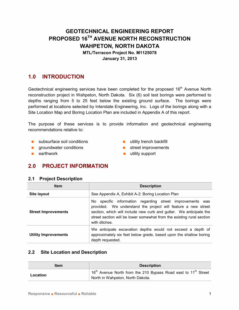
January 31, 2013 1.0 INTRODUCTION Geotechnical engineering services have been completed for the proposed 16th Avenue North reconstruction project in Wahpeton, North Dakota. Six (6) soil test borings were performed to depths ranging from 5 to 25 feet below the existing ground surface. The borings were performed at locations selected by Interstate Engineering, Inc. Logs of the borings along with a Site Location Map and Boring Location Plan are included in Appendix A of this report. The purpose of these services is to provide information and geotechnical engineering recommendations relative to: subsurface soil conditions utility trench backfill groundwater conditions street improvements earthwork utility support
2.0 PROJECT INFORMATION 2.1 Project Description
Item Description
Site layout See Appendix A, Exhibit A-2: Boring Location Plan
Street Improvements
No specific information regarding street improvements was provided. We understand the project will feature a new street section, which will include new curb and gutter. We anticipate the street section will be lower somewhat from the existing rural section with ditches.
Utility Improvements We anticipate excavation depths would not exceed a depth of approximately six feet below grade, based upon the shallow boring depth requested.
2.2 Site Location and Description
Item Description
Location 16th Avenue North from the 210 Bypass Road east to 11th Street North in Wahpeton, North Dakota.

Geotechnical Engineering Report Proposed 16th Avenue North Reconstruction ■ Wahpeton, North Dakota January 31, 2013 ■ MTL/Terracon Project No. M1125078
Responsive ■ Resourceful ■ Reliable 2
Item Description
Current ground cover Asphalt pavement
Existing topography Relatively flat
3.0 SUBSURFACE CONDITIONS 3.1 Typical Pavement and Soil Profile
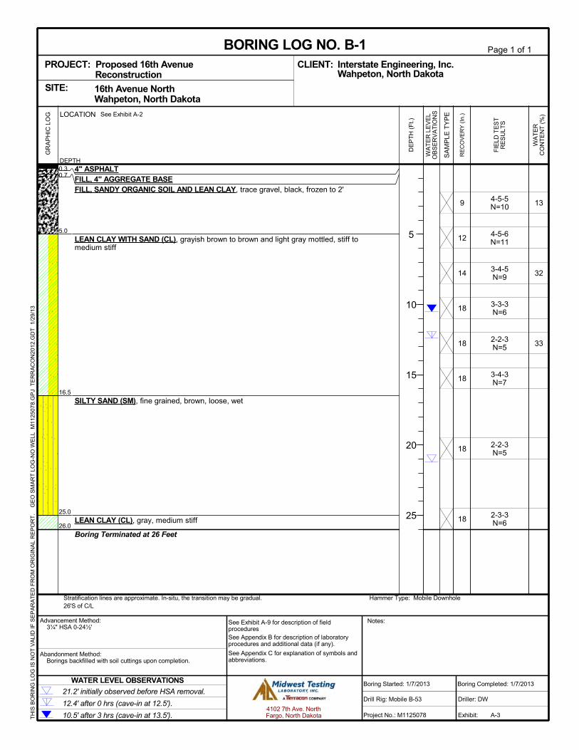
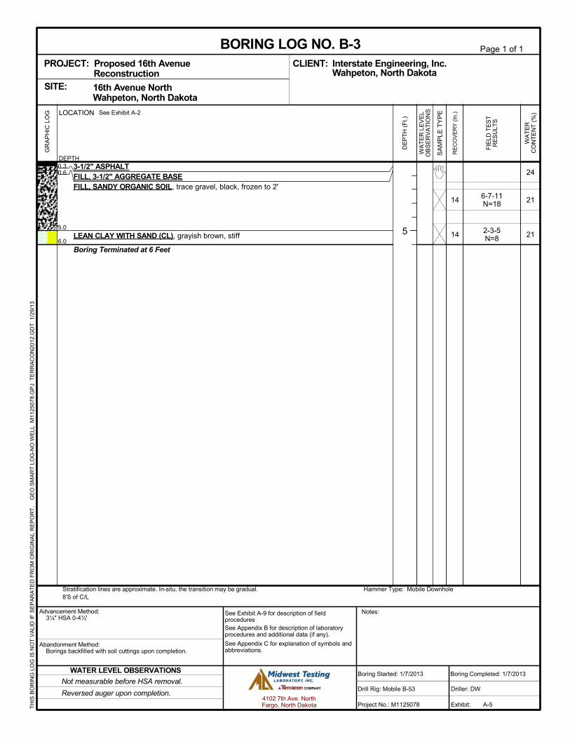
The test borings indicate the pavement ranges in thickness from approximately 3 ½ to 4 inches. Below the asphalt, granular base material was encountered which ranges in thickness from approximately 3½ to 6 inches. Below the granular base, fill soils consisting primarily of sandy organic soil and lean clays were encountered to depths approximately 4 to 5 feet below the existing ground surface. Most of the fill is black in color and contains a trace of gravel. Below the fill and organic soil, the soil conditions consist primarily of lean clay, lean clay with sand and fat clay. These natural clays are typically medium stiff to stiff in consistency. At Boring B-1, the natural lean clay with sand is found to extend to a depth of approximately 16.5 feet and was underlain by a fine grained silty sand with a loose density. At 25 feet, a gray lean clay was encountered which extends to the termination depth of the boring (26 feet). Conditions at each boring location are indicated on the attached individual boring logs. Stratification boundaries on the boring logs represent the approximate location of changes in soil types; in situ, the transition between materials may be gradual. Details for each of the borings can be found on the boring logs in Appendix A of this report. A discussion of the field sampling is included in Appendix A. 3.2 Groundwater
Groundwater was not measurable in any of the five shallow borings performed within the street section. Boring B-1 was extended to a depth of 25 feet and a ground water level of approximately 21 feet was measured upon completion of the boring. After a period of 3 hours, our final ground water level measurement was 10.5 feet below the ground surface. Due to safety concerns, each boring was backfilled and patched with asphalt. Due to the low permeability of the clay soils encountered within the borings, a long period of time may be needed to establish a ground water level. Long-term observations from piezometers or observation wells sealed from the influence of surface water are often required to define groundwater levels in cohesive soils. Based on the measurement data, we estimate the ground water level was located approximately 6 to 10 feet below grade at the time of our field activities.

Geotechnical Engineering Report Proposed 16th Avenue North Reconstruction ■ Wahpeton, North Dakota January 31, 2013 ■ MTL/Terracon Project No. M1125078
Responsive ■ Resourceful ■ Reliable 3
Groundwater level fluctuations should be expected to occur due to seasonal variations in rainfall, runoff and other factors. Therefore, groundwater levels during construction or at other times in the life of the structure may be higher or lower than the levels indicated on the boring logs. The possibility of groundwater level fluctuations should be considered when developing the design and construction plans for the project. 4.0 RECOMMENDATIONS FOR DESIGN AND CONSTRUCTION 4.1 Geotechnical Considerations
The test borings indicate the existing pavement thickness ranges from approximately 3.5 to 4 inches. Below the pavement, we measured approximately 3½ to 6 inches of aggregate base material. The subgrade soils within the road bed consist mostly of a sandy organic soil which is black in color and extends approximately 4 to 5 feet below grade. Generally, to obtain improved pavement performance, the best option for a new roadway would be remove these organic soils from beneath the paved areas. However, we understand this amount of excavation and fill replacement may be cost prohibitive, depending upon the new elevation of the street. If the black organic soils are allowed to remain below the new street, the owner must be willing to accept some risk of settlement and a lower level of pavement performance. We would expect the new street would have similar performance to the previous street section. To reduce the potential for differential frost heave, we recommend reusing the native inorganic soils excavated from utility trenches for trench backfill. Utility trenches which are backfilled with clean sand can exhibit undesirable differential frost heaving on an annual basis. The clay subgrade soils should be considered highly susceptible to frost heaving. Therefore, seasonal movement should be expected as frost penetrates the clay subgrade to depths on the order of 6 to 8 feet. These soils will also experience a significant loss of strength during spring thaw. Therefore, cracking of the pavement should be expected due to frost action and extreme temperature variations. Frost heaving could be prevented by replacing the clay subgrade soils with a clean, non-frost susceptible sand and gravel maintained in a drained condition. We understand this option is cost prohibitive. 4.2 Earthwork
4.2.1 Site Preparation As discussed above, the best option for subgrade preparation in the street areas would be to remove all organic soils from below the new pavement. The test borings indicate excavation depths on the order of 4 to 5 feet below existing grade would be needed. If this amount of

Geotechnical Engineering Report Proposed 16th Avenue North Reconstruction ■ Wahpeton, North Dakota January 31, 2013 ■ MTL/Terracon Project No. M1125078
Responsive ■ Resourceful ■ Reliable 4
overexavation is cost prohibitive, organic soils could remain below the pavement areas and a reduced level of pavement performance would be expected, as compared to an inorganic soil subgrade. 4.2.2 Material Types Compacted structural fill should meet the following material property requirements:
Fill Type 1 USCS Classification Acceptable Location for Placement
Select Granular Fill SP, SP-SM, SP-SC, SW, SW-SM, SW-SC
(P200<12%) Pavement Subgrade
On-site soils CL, CH, OL Utility Trench Backfill and Pavement Subgrade
1. Controlled, compacted fill should consist of approved materials that are free of debris, or other deleterious substance. Frozen material should not be used, and fill should not be placed on a frozen subgrade. A sample of each material type should be submitted to the geotechnical engineer for evaluation.
4.2.3 Compaction Requirements
ITEM DESCRIPTION
Fill Lift Thickness
9-inches or less in loose thickness when heavy, self-propelled compaction equipment is used 4 to 6 inches in loose thickness when hand-guided equipment (i.e. jumping jack, plate compactor, etc.) is used
Compaction Requirements 1 98% for final 1 foot below pavement cross-section 95% deeper than 1 foot below the pavement cross-section
Moisture Content Cohesive Soil +/- 3% of Standard Proctor optimum moisture
Moisture Content Granular Material2 Workable moisture levels
1. We recommend that engineered fill be tested for moisture content and compaction during placement. Should the results of the in-place density tests indicate the specified moisture or compaction limits have not been met, the area represented by the test should be reworked and retested as required until the specified moisture and compaction requirements are achieved. Compaction levels are relative to the soil’s Standard Proctor maximum dry density (ASTM D698).
2. Specifically, moisture levels should be maintained low enough to allow for satisfactory compaction to be achieved without the cohesionless fill material pumping when proofrolled.
4.2.4 Utility Trench Backfill Utility trench backfill should be compacted as recommended in Section 4.2.3. Excavations should be performed in accordance with governing safety regulations. All vehicles and soil piles should be kept back from the crest of excavation slopes. The stability of excavation slopes
Geotechnical Engineering Report Proposed 16th Avenue North Reconstruction ■ Wahpeton, North Dakota January 31, 2013 ■ MTL/Terracon Project No. M1125078
Responsive ■ Resourceful ■ Reliable 5
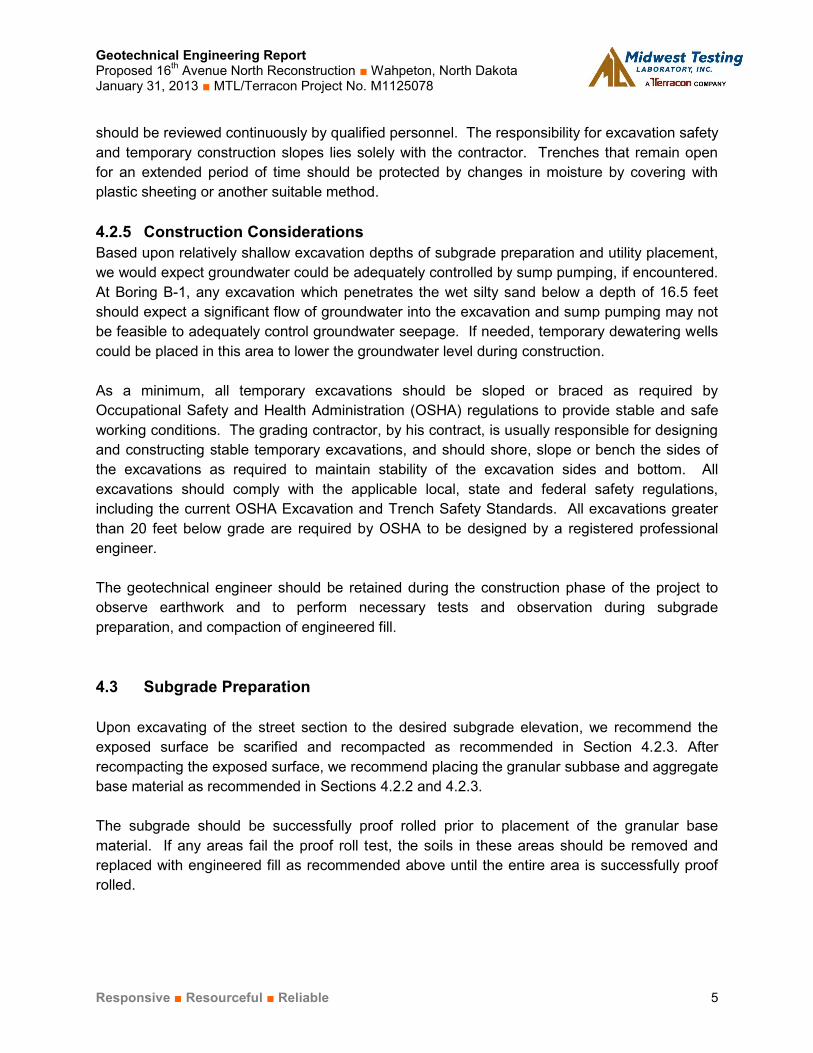
should be reviewed continuously by qualified personnel. The responsibility for excavation safety and temporary construction slopes lies solely with the contractor. Trenches that remain open for an extended period of time should be protected by changes in moisture by covering with plastic sheeting or another suitable method. 4.2.5 Construction Considerations Based upon relatively shallow excavation depths of subgrade preparation and utility placement, we would expect groundwater could be adequately controlled by sump pumping, if encountered. At Boring B-1, any excavation which penetrates the wet silty sand below a depth of 16.5 feet should expect a significant flow of groundwater into the excavation and sump pumping may not be feasible to adequately control groundwater seepage. If needed, temporary dewatering wells could be placed in this area to lower the groundwater level during construction. As a minimum, all temporary excavations should be sloped or braced as required by Occupational Safety and Health Administration (OSHA) regulations to provide stable and safe working conditions. The grading contractor, by his contract, is usually responsible for designing and constructing stable temporary excavations, and should shore, slope or bench the sides of the excavations as required to maintain stability of the excavation sides and bottom. All excavations should comply with the applicable local, state and federal safety regulations, including the current OSHA Excavation and Trench Safety Standards. All excavations greater than 20 feet below grade are required by OSHA to be designed by a registered professional engineer. The geotechnical engineer should be retained during the construction phase of the project to observe earthwork and to perform necessary tests and observation during subgrade preparation, and compaction of engineered fill. 4.3 Subgrade Preparation
Upon excavating of the street section to the desired subgrade elevation, we recommend the exposed surface be scarified and recompacted as recommended in Section 4.2.3. After recompacting the exposed surface, we recommend placing the granular subbase and aggregate base material as recommended in Sections 4.2.2 and 4.2.3. The subgrade should be successfully proof rolled prior to placement of the granular base material. If any areas fail the proof roll test, the soils in these areas should be removed and replaced with engineered fill as recommended above until the entire area is successfully proof rolled.

Geotechnical Engineering Report Proposed 16th Avenue North Reconstruction ■ Wahpeton, North Dakota January 31, 2013 ■ MTL/Terracon Project No. M1125078
Responsive ■ Resourceful ■ Reliable 6
We recommend the moisture content and density of the upper 1 foot of the subgrade be evaluated and the pavement subgrade proof rolled within 2 days prior to commencement of the actual paving operations. 4.4 Pavement Design Parameters
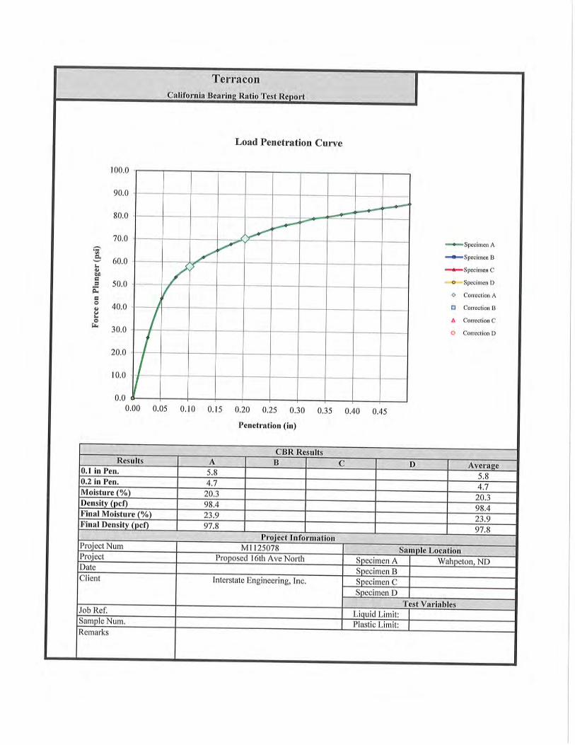
One CBR test was performed on a composite sample collected from Borings B-2 and B-5 from 2 to 4½ feet below grade. When compacted to approximately 95 percent of the Standard Proctor maximum density, a CBR value of 5.8 was measured. We recommend using a CBR value of no greater than 5 in the pavement thickness design for the roadway. We recommend consideration be given to the use of a separate fabric between the clay subgrade and any aggregate base or subbase material. The separation fabric will help improve the performance of the clay subgrade during spring thaw and other wet seasonal periods. 4.5 Pavement Drainage
Pavements should be sloped to provide rapid drainage of surface water. Water allowed to pond on or adjacent to the pavements could saturate the subgrade and contribute to premature pavement deterioration. In addition, the pavement subgrade should be graded to provide positive drainage within the granular base section. Appropriate sub-drainage or connection to a suitable day light outlet should be provided to remove water from the granular base/sub-base. 4.5.1 Pavement Maintenance Pavement maintenance should be planned and provided though an on-going pavement management program. Preventative maintenance activities are intended to slow the rate of pavement deterioration, and to preserve the pavement investment. Preventative maintenance consists of both localized maintenance (e.g. crack and joint sealing and patching) and global maintenance (e.g. surface sealing). Preventative maintenance is usually the first priority when implementing a planned pavement maintenance program and provides the highest return on investment for pavements. Prior to implementing any maintenance, additional engineering observation is recommended to determine the type and extent of preventative maintenance. Even with periodic maintenance, movements and cracking related to frost heaving and extreme temperature variations will still occur and repairs may be required. 5.0 GENERAL COMMENTS MTL/Terracon should be retained to review the final design plans and specifications so comments can be made regarding interpretation and implementation of our geotechnical

Geotechnical Engineering Report Proposed 16th Avenue North Reconstruction ■ Wahpeton, North Dakota January 31, 2013 ■ MTL/Terracon Project No. M1125078
Responsive ■ Resourceful ■ Reliable 7
recommendations in the design and specifications. MTL/Terracon also should be retained to provide observation and testing services during grading, excavation, foundation construction and other earth-related construction phases of the project. The analysis and recommendations presented in this report are based upon the data obtained from the borings performed at the indicated locations and from other information discussed in this report. This report does not reflect variations that may occur between borings, across the site, or due to the modifying effects of construction or weather. The nature and extent of such variations may not become evident until during or after construction. If variations appear, we should be immediately notified so that further evaluation and supplemental recommendations can be provided. The scope of services for this project does not include either specifically or by implication any environmental or biological (e.g., mold, fungi, bacteria) assessment of the site or identification or prevention of pollutants, hazardous materials or conditions. If the owner is concerned about the potential for such contamination or pollution, other studies should be undertaken. This report has been prepared for the exclusive use of our client for specific application to the project discussed and has been prepared in accordance with generally accepted geotechnical engineering practices. No warranties, either express or implied, are intended or made. Site safety, excavation support, and dewatering requirements are the responsibility of others. In the event that changes in the nature, design, or location of the project as outlined in this report are planned, the conclusions and recommendations contained in this report shall not be considered valid unless MTL/Terracon reviews the changes and either verifies or modifies the conclusions of this report in writing.

APPENDIX A FIELD EXPLORATION

DIAGRAM IS FOR GENERAL LOCATION ONLY, AND IS NOT INTENDED FOR CONSTRUCTION PURPOSES
4102 7th Avenue North Fargo, North Dakota 58102
PH. (701) 282-9633 FAX. (701) 282-9635A-1
EXHIBITSITE LOCATION MAP Proposed 16th Avenue North Reconstruction
210 Bypass Road to 11th Street NorthWahpeton, North Dakota
Project Manager:
Drawn by:Checked by:
Approved by:
LMFlmf
LMF
LMF
Project No.
Scale:
Date:
M1125078See above
1-29-2013
Project Site
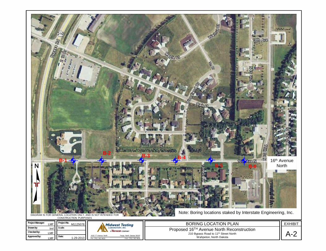
DIAGRAM IS FOR GENERAL LOCATION ONLY, AND IS NOT INTENDED FOR CONSTRUCTION PURPOSES
4102 7th Avenue North Fargo, North Dakota 58102
PH. (701) 282-9633 FAX. (701) 282-9635A-2
EXHIBITBORING LOCATION PLAN Proposed 16TH Avenue North Reconstruction
210 Bypass Road to 11th Street NorthWahpeton, North Dakota
Project Manager:
Drawn by:Checked by:
Approved by:
LMFlmf
LMF
LMF
Project No.
Scale:
Date:
M1125078
1-29-2013
B-1B-2
B-6
B-4B-3
B-516th Avenue
North
Note: Boring locations staked by Interstate Engineering, Inc.
0.30.7
5.0
16.5
25.0
26.0
4" ASPHALTFILL, 4" AGGREGATE BASEFILL, SANDY ORGANIC SOIL AND LEAN CLAY, trace gravel, black, frozen to 2'
LEAN CLAY WITH SAND (CL), grayish brown to brown and light gray mottled, stiff tomedium stiff
SILTY SAND (SM), fine grained, brown, loose, wet
LEAN CLAY (CL), gray, medium stiff
Boring Terminated at 26 Feet
9
12
14
18
18
18
18
18
13
32
33
4-5-5N=10
4-5-6N=11
3-4-5N=9
3-3-3N=6
2-2-3N=5
3-4-3N=7
2-2-3N=5
2-3-3N=6
See Exhibit A-2
Hammer Type: Mobile DownholeStratification lines are approximate. In-situ, the transition may be gradual.26'S of C/L
LOCATION
DEPTH
GR
AP
HIC
LO
G
TH
IS B
OR
ING
LO
G IS
NO
T V
ALI
D IF
SE
PA
RA
TE
D F
RO
M O
RIG
INA
L R
EP
OR
T.
G
EO
SM
AR
T L
OG
-NO
WE
LL M
1125
078
.GP
J T
ER
RA
CO
N20
12.G
DT
1/2
9/13
16th Avenue North Wahpeton, North DakotaSITE:
21.2' initially observed before HSA removal.
12.4' after 0 hrs (cave-in at 12.5').
10.5' after 3 hrs (cave-in at 13.5').
WATER LEVEL OBSERVATIONS
PROJECT: Proposed 16th AvenueReconstruction
Page 1 of 1
Advancement Method:3¼" HSA 0-24½'
Abandonment Method:Borings backfilled with soil cuttings upon completion.
4102 7th Ave. NorthFargo, North Dakota
Notes:
Project No.: M1125078
Drill Rig: Mobile B-53
Boring Started: 1/7/2013
BORING LOG NO. B-1Interstate Engineering, Inc.CLIENT:Wahpeton, North Dakota
Driller: DW
Boring Completed: 1/7/2013
Exhibit: A-3
See Exhibit A-9 for description of fieldproceduresSee Appendix B for description of laboratoryprocedures and additional data (if any).
See Appendix C for explanation of symbols andabbreviations.
RE
CO
VE
RY
(In
.)
WA
TE
RC
ON
TE
NT
(%
)
FIE
LD T
ES
TR
ES
ULT
S
WA
TE
R L
EV
EL
OB
SE
RV
AT
ION
S
DE
PT
H (
Ft.)
5
10
15
20
25
SA
MP
LE T
YP
E

0.30.8
4.5
6.0
3 3/4" ASPHALTFILL, 6" AGGREGATE BASEFILL, SANDY ORGANIC SOIL AND LEAN CLAY, trace gravel, mostly black, frozen to 2'
LEAN CLAY WITH SAND (CL), grayish brown, stiff
Boring Terminated at 6 Feet
14
12
29
29
31
5-8-9N=17
4-3-5N=8
See Exhibit A-2
Hammer Type: Mobile DownholeStratification lines are approximate. In-situ, the transition may be gradual.8'N of C/L
LOCATION
DEPTH
GR
AP
HIC
LO
G
TH
IS B
OR
ING
LO
G IS
NO
T V
ALI
D IF
SE
PA
RA
TE
D F
RO
M O
RIG
INA
L R
EP
OR
T.
G
EO
SM
AR
T L
OG
-NO
WE
LL M
1125
078
.GP
J T
ER
RA
CO
N20
12.G
DT
1/2
9/13
16th Avenue North Wahpeton, North DakotaSITE:
Not measurable before HSA removal.
Reversed auger upon completion.
WATER LEVEL OBSERVATIONS
PROJECT: Proposed 16th AvenueReconstruction
Page 1 of 1
Advancement Method:3¼" HSA 0-4½'
Abandonment Method:Borings backfilled with soil cuttings upon completion.
4102 7th Ave. NorthFargo, North Dakota
Notes:
Project No.: M1125078
Drill Rig: Mobile B-53
Boring Started: 1/7/2013
BORING LOG NO. B-2Interstate Engineering, Inc.CLIENT:Wahpeton, North Dakota
Driller: DW
Boring Completed: 1/7/2013
Exhibit: A-4
See Exhibit A-9 for description of fieldproceduresSee Appendix B for description of laboratoryprocedures and additional data (if any).
See Appendix C for explanation of symbols andabbreviations.
RE
CO
VE
RY
(In
.)
WA
TE
RC
ON
TE
NT
(%
)
FIE
LD T
ES
TR
ES
ULT
S
WA
TE
R L
EV
EL
OB
SE
RV
AT
ION
S
DE
PT
H (
Ft.)
5
SA
MP
LE T
YP
E
0.30.6
5.0
6.0
3-1/2" ASPHALTFILL, 3-1/2" AGGREGATE BASEFILL, SANDY ORGANIC SOIL, trace gravel, black, frozen to 2'
LEAN CLAY WITH SAND (CL), grayish brown, stiff
Boring Terminated at 6 Feet
14
14
24
21
21
6-7-11N=18
2-3-5N=8
See Exhibit A-2
Hammer Type: Mobile DownholeStratification lines are approximate. In-situ, the transition may be gradual.8'S of C/L
LOCATION
DEPTH
GR
AP
HIC
LO
G
TH
IS B
OR
ING
LO
G IS
NO
T V
ALI
D IF
SE
PA
RA
TE
D F
RO
M O
RIG
INA
L R
EP
OR
T.
G
EO
SM
AR
T L
OG
-NO
WE
LL M
1125
078
.GP
J T
ER
RA
CO
N20
12.G
DT
1/2
9/13
16th Avenue North Wahpeton, North DakotaSITE:
Not measurable before HSA removal.
Reversed auger upon completion.
WATER LEVEL OBSERVATIONS
PROJECT: Proposed 16th AvenueReconstruction
Page 1 of 1
Advancement Method:3¼" HSA 0-4½'
Abandonment Method:Borings backfilled with soil cuttings upon completion.
4102 7th Ave. NorthFargo, North Dakota
Notes:
Project No.: M1125078
Drill Rig: Mobile B-53
Boring Started: 1/7/2013
BORING LOG NO. B-3Interstate Engineering, Inc.CLIENT:Wahpeton, North Dakota
Driller: DW
Boring Completed: 1/7/2013
Exhibit: A-5
See Exhibit A-9 for description of fieldproceduresSee Appendix B for description of laboratoryprocedures and additional data (if any).
See Appendix C for explanation of symbols andabbreviations.
RE
CO
VE
RY
(In
.)
WA
TE
RC
ON
TE
NT
(%
)
FIE
LD T
ES
TR
ES
ULT
S
WA
TE
R L
EV
EL
OB
SE
RV
AT
ION
S
DE
PT
H (
Ft.)
5
SA
MP
LE T
YP
E

0.30.8
5.0
6.0
4" ASPHALTFILL, 6" AGGREGATE BASEFILL, SANDY ORGANIC SOIL, trace gravel, black, frozen to 2'
LEAN CLAY WITH SAND (CL), light grayish brown, stiff
Boring Terminated at 6 Feet
16
12
24
19
27
22-16-9N=25
3-4-6N=10
See Exhibit A-2
Hammer Type: Mobile DownholeStratification lines are approximate. In-situ, the transition may be gradual.7'N of C/L
LOCATION
DEPTH
GR
AP
HIC
LO
G
TH
IS B
OR
ING
LO
G IS
NO
T V
ALI
D IF
SE
PA
RA
TE
D F
RO
M O
RIG
INA
L R
EP
OR
T.
G
EO
SM
AR
T L
OG
-NO
WE
LL M
1125
078
.GP
J T
ER
RA
CO
N20
12.G
DT
1/2
9/13
16th Avenue North Wahpeton, North DakotaSITE:
Not measurable before HSA removal.
Reversed auger upon completion.
WATER LEVEL OBSERVATIONS
PROJECT: Proposed 16th AvenueReconstruction
Page 1 of 1
Advancement Method:3¼" HSA 0-4½'
Abandonment Method:Borings backfilled with soil cuttings upon completion.
4102 7th Ave. NorthFargo, North Dakota
Notes:
Project No.: M1125078
Drill Rig: Mobile B-53
Boring Started: 1/7/2013
BORING LOG NO. B-4Interstate Engineering, Inc.CLIENT:Wahpeton, North Dakota
Driller: DW
Boring Completed: 1/7/2013
Exhibit: A-6
See Exhibit A-9 for description of fieldproceduresSee Appendix B for description of laboratoryprocedures and additional data (if any).
See Appendix C for explanation of symbols andabbreviations.
RE
CO
VE
RY
(In
.)
WA
TE
RC
ON
TE
NT
(%
)
FIE
LD T
ES
TR
ES
ULT
S
WA
TE
R L
EV
EL
OB
SE
RV
AT
ION
S
DE
PT
H (
Ft.)
5
SA
MP
LE T
YP
E

0.30.7
4.5
6.0
4" ASPHALTFILL, 4" AGGREGATE BASEFILL, SANDY ORGANIC SOIL AND LEAN CLAY, trace gravel, mostly black, frozen to 2'
LEAN CLAY WITH SAND (CL), brown, stiff
Boring Terminated at 6 Feet
14
10
17
19
7-5-6N=11
3-4-5N=9
See Exhibit A-2
Hammer Type: Mobile DownholeStratification lines are approximate. In-situ, the transition may be gradual.6.5'S of C/L
LOCATION
DEPTH
GR
AP
HIC
LO
G
TH
IS B
OR
ING
LO
G IS
NO
T V
ALI
D IF
SE
PA
RA
TE
D F
RO
M O
RIG
INA
L R
EP
OR
T.
G
EO
SM
AR
T L
OG
-NO
WE
LL M
1125
078
.GP
J T
ER
RA
CO
N20
12.G
DT
1/2
9/13
16th Avenue North Wahpeton, North DakotaSITE:
Not measurable before HSA removal.
Reversed auger upon completion.
WATER LEVEL OBSERVATIONS
PROJECT: Proposed 16th AvenueReconstruction
Page 1 of 1
Advancement Method:3¼" HSA 0-4½'
Abandonment Method:Borings backfilled with soil cuttings upon completion.
4102 7th Ave. NorthFargo, North Dakota
Notes:
Project No.: M1125078
Drill Rig: Mobile B-53
Boring Started: 1/7/2013
BORING LOG NO. B-5Interstate Engineering, Inc.CLIENT:Wahpeton, North Dakota
Driller: DW
Boring Completed: 1/7/2013
Exhibit: A-7
See Exhibit A-9 for description of fieldproceduresSee Appendix B for description of laboratoryprocedures and additional data (if any).
See Appendix C for explanation of symbols andabbreviations.
RE
CO
VE
RY
(In
.)
WA
TE
RC
ON
TE
NT
(%
)
FIE
LD T
ES
TR
ES
ULT
S
WA
TE
R L
EV
EL
OB
SE
RV
AT
ION
S
DE
PT
H (
Ft.)
5
SA
MP
LE T
YP
E

0.30.7
3.0
4.0
6.0
4" ASPHALTFILL, 4-1/2" AGGREGATE BASEFILL, LEAN CLAY WITH SAND AND SANDY ORGANIC SOIL, trace gravel, dark gray and black,frozen to 2'
TOPSOIL, ORGANIC SOIL (OL), black
FAT CLAY (CH), dark grayish brown, stiff
Boring Terminated at 6 Feet
30
27
3-4-7N=11
4-4-7N=11
See Exhibit A-2
Hammer Type: Mobile DownholeStratification lines are approximate. In-situ, the transition may be gradual.10'N of C/L
LOCATION
DEPTH
GR
AP
HIC
LO
G
TH
IS B
OR
ING
LO
G IS
NO
T V
ALI
D IF
SE
PA
RA
TE
D F
RO
M O
RIG
INA
L R
EP
OR
T.
G
EO
SM
AR
T L
OG
-NO
WE
LL M
1125
078
.GP
J T
ER
RA
CO
N20
12.G
DT
1/2
9/13
16th Avenue North Wahpeton, North DakotaSITE:
Not measurable before HSA removal.
Reversed auger upon completion.
WATER LEVEL OBSERVATIONS
PROJECT: Proposed 16th AvenueReconstruction
Page 1 of 1
Advancement Method:3¼" HSA 0-4½'
Abandonment Method:Borings backfilled with soil cuttings upon completion.
4102 7th Ave. NorthFargo, North Dakota
Notes:
Project No.: M1125078
Drill Rig: Mobile B-53
Boring Started: 1/7/2013
BORING LOG NO. B-6Interstate Engineering, Inc.CLIENT:Wahpeton, North Dakota
Driller: DW
Boring Completed: 1/7/2013
Exhibit: A-8
See Exhibit A-9 for description of fieldproceduresSee Appendix B for description of laboratoryprocedures and additional data (if any).
See Appendix C for explanation of symbols andabbreviations.
WA
TE
RC
ON
TE
NT
(%
)
FIE
LD T
ES
TR
ES
ULT
S
WA
TE
R L
EV
EL
OB
SE
RV
AT
ION
S
DE
PT
H (
Ft.)
5
SA
MP
LE T
YP
E
Geotechnical Engineering Report Proposed 16th Avenue North Reconstruction ■ Wahpeton, North Dakota January 31, 2013 ■ MTL/Terracon Project No. M1125078
Responsive ■ Resourceful ■ Reliable Exhibit A-9
Field Exploration Description Six soil test borings were completed for the project on January 7, 2013. The borings were advanced at the approximate locations indicated on Exhibit A-2. The borings were performed at staked locations provided by Interstate Engineering, Inc. Ground surface elevations at the boring locations were not determined. The test borings were completed with a Mobile B-53 truck-mounted drill rig using 3¼ hollow stem to advance boreholes. Soil samples were obtained using both split-barrel and Shelby tube sampling procedures. In the split-barrel sampling procedure the number of blows required to advance a standard 2-inch O.D., 1-3/8-inch I.D spilt-barrel sampler from 6 to 18 inches of penetration by means of a 140-pound hammer with a free fall of 30 inches is used to obtain the Standard Penetration Test (SPT) or N-value. The SPT is used to estimate the in-situ relative density of cohesionless soils and the consistency of cohesive soils. In the Shelby tube sampling procedure, a thin wall seamless steel tube with a sharp cutting edge is pushed into the soil by hydraulic pressure to obtain a relatively undisturbed sample of cohesive soil. A Mobile down-hole hammer was used to advance the split spoon sampler. A somewhat reduced efficiency is typically achieved with the down-hole hammer compared to the conventional safety hammer operated with a cathead and rope. The efficiency of the hammer can have an appreciable affect on the standard penetration resistance blow count (N) values. The effect of the down-hole hammer’s efficiency has been considered in the interpretation and analysis of the subsurface information for this report. The samples were tagged for identification, sealed to reduce moisture loss, and taken to our laboratory for further examination, testing, and classification. Information provided on the boring logs attached to this report includes soil descriptions, consistency evaluations, boring depths, sampling intervals, and groundwater conditions. The borings were backfilled with auger cuttings prior to the drill crew leaving the site. A field log of each boring was prepared by the drill crew. These logs included visual classifications of the materials encountered during drilling as well as the driller’s interpretation of the subsurface conditions between samples. Final boring logs included with this report represent the engineer's interpretation of the field logs and include modifications based on laboratory observation and tests of the samples.

APPENDIX B SUPPORTING INFORMATION

Geotechnical Engineering Report Proposed 16th Avenue North Reconstruction ■ Wahpeton, North Dakota January 31, 2013 ■ MTL/Terracon Project No. M1125078
Responsive ■ Resourceful ■ Reliable Exhibit B-1
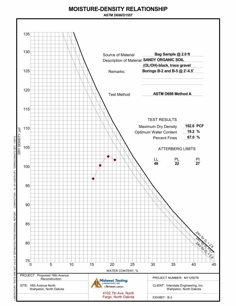
Laboratory Testing Representative samples were selected for laboratory analysis. The testing program consisted of determining the moisture content of the subgrade soils. The laboratory test results are found on the boring logs opposite the samples they represent. Bag samples of subgrade soils collected from Borings B-2 and B-5 were tested to determine the moisture-density relationship (ASTM D698), Atterberg limits and percent passing the #200 sieve. A sample of the subgrade material was then recompacted to 96 percent of ASTM D698 and tested to determine the California Bearing Ratio (CBR). The moisture-density relation, Atterberg, minus 200 and CBR test results are shown on Exhibits B-2 and B-3. Descriptive classifications of the soils indicated on the boring logs are in accordance with the enclosed General Notes and the Unified Soil Classification System. Also shown are estimated Unified Soil Classification Symbols. A brief description of this classification system is attached to this report. All classification was by visual manual procedures. Selected samples were further classified using the results of Atterberg limit testing. The Atterberg limit test results are also provided on the boring logs.
75
80
85
90
95
100
105
110
115
120
125
130
135
0 5 10 15 20 25 30 35 40 45
Test Method
Remarks:
TEST RESULTS
PIPLLL
ATTERBERG LIMITS
49 22 27
PCF
% Maximum Dry Density
Optimum Water Content
102.6
% Percent Fines
Borings B-2 and B-5 @ 2'-4.5'
ASTM D698 Method A
Bag Sample @ 2.0 ft
19.2
67.0
SANDY ORGANIC SOIL
(OL/OH)-black, trace gravel
DR
Y D
EN
SIT
Y,
pcf
WATER CONTENT, %
ZAV for Gs = 2.8
ZAV for Gs = 2.7
ZAV for Gs = 2.6
Source of Material
Description of Material
MOISTURE-DENSITY RELATIONSHIPASTM D698/D1557
EXHIBIT: B-24102 7th Ave. NorthFargo, North Dakota
PROJECT NUMBER: M1125078PROJECT: Proposed 16th Avenue
Reconstruction
SITE: 16th Avenue North Wahpeton, North Dakota
CLIENT: Interstate Engineering, Inc. Wahpeton, North Dakota
LAB
OR
AT
OR
Y T
ES
TS
AR
E N
OT
VA
LID
IF S
EP
AR
AT
ED
FR
OM
OR
IGIN
AL
RE
PO
RT
.
CO
MP
AC
TIO
N -
V2
M11
250
78.G
PJ
TE
RR
AC
ON
2012
.GD
T 1
/29/
13

APPENDIX C SUPPORTING DOCUMENTS

TraceWithModifier
Water Level Aftera Specified Period of Time
GRAIN SIZE TERMINOLOGYRELATIVE PROPORTIONS OF SAND AND GRAVEL
TraceWithModifier
Standard Penetration orN-Value
Blows/Ft.
Descriptive Term(Consistency)
Loose
Very Stiff
Exhibit C-1
Standard Penetration orN-Value
Blows/Ft.
Ring SamplerBlows/Ft.
Ring SamplerBlows/Ft.
Medium Dense
Dense
Very Dense
0 - 1 < 3
4 - 9 2 - 4 3 - 4
Medium-Stiff 5 - 7 5 - 9
30 - 50
WA
TE
R L
EV
EL
Auger
Shelby Tube
Ring Sampler
Grab Sample
Split Spoon
Macro Core
Rock Core
PLASTICITY DESCRIPTION
Term
< 1515 - 29> 30
Descriptive Term(s)of other constituents
Water InitiallyEncountered
Water Level After aSpecified Period of Time
Major Componentof Sample
Percent ofDry Weight
(More than 50% retained on No. 200 sieve.)Density determined by Standard Penetration Resistance
Includes gravels, sands and silts.
Hard
Very Loose 0 - 3 0 - 6 Very Soft
7 - 18 Soft
10 - 29 19 - 58
59 - 98 Stiff
less than 500
500 to 1,000
1,000 to 2,000
2,000 to 4,000
4,000 to 8,000> 99
LOCATION AND ELEVATION NOTES
SA
MP
LIN
G
FIE
LD
TE
ST
S
(HP)
(T)
(b/f)
(PID)
(OVA)
DESCRIPTION OF SYMBOLS AND ABBREVIATIONS
Descriptive Term(Density)
Non-plasticLowMediumHigh
BouldersCobblesGravelSandSilt or Clay
8 - 14 10 - 18
> 50 15 - 30 19 - 42
> 30 > 42
_
Hand Penetrometer
Torvane
Standard PenetrationTest (blows per foot)
Photo-Ionization Detector
Organic Vapor Analyzer
Water levels indicated on the soil boringlogs are the levels measured in theborehole at the times indicated.Groundwater level variations will occurover time. In low permeability soils,accurate determination of groundwaterlevels is not possible with short termwater level observations.
CONSISTENCY OF FINE-GRAINED SOILS
(50% or more passing the No. 200 sieve.)Consistency determined by laboratory shear strength testing, field
visual-manual procedures or standard penetration resistance
DESCRIPTIVE SOIL CLASSIFICATION
> 8,000
Unless otherwise noted, Latitude and Longitude are approximately determined using a hand-held GPS device. The accuracyof such devices is variable. Surface elevation data annotated with +/- indicates that no actual topographical survey wasconducted to confirm the surface elevation. Instead, the surface elevation was approximately determined from topographicmaps of the area.
Soil classification is based on the Unified Soil Classification System. Coarse Grained Soils have more than 50% of their dryweight retained on a #200 sieve; their principal descriptors are: boulders, cobbles, gravel or sand. Fine Grained Soils haveless than 50% of their dry weight retained on a #200 sieve; they are principally described as clays if they are plastic, andsilts if they are slightly plastic or non-plastic. Major constituents may be added as modifiers and minor constituents may beadded according to the relative proportions based on grain size. In addition to gradation, coarse-grained soils are definedon the basis of their in-place relative density and fine-grained soils on the basis of their consistency.
Plasticity Index
01 - 1011 - 30
> 30
RELATIVE PROPORTIONS OF FINES
Descriptive Term(s)of other constituents
Percent ofDry Weight
< 55 - 12> 12
No Recovery
RELATIVE DENSITY OF COARSE-GRAINED SOILS
Particle Size
Over 12 in. (300 mm)12 in. to 3 in. (300mm to 75mm)3 in. to #4 sieve (75mm to 4.75 mm)#4 to #200 sieve (4.75mm to 0.075mmPassing #200 sieve (0.075mm)
ST
RE
NG
TH
TE
RM
S Unconfined CompressiveStrength, Qu, psf
GENERAL NOTES
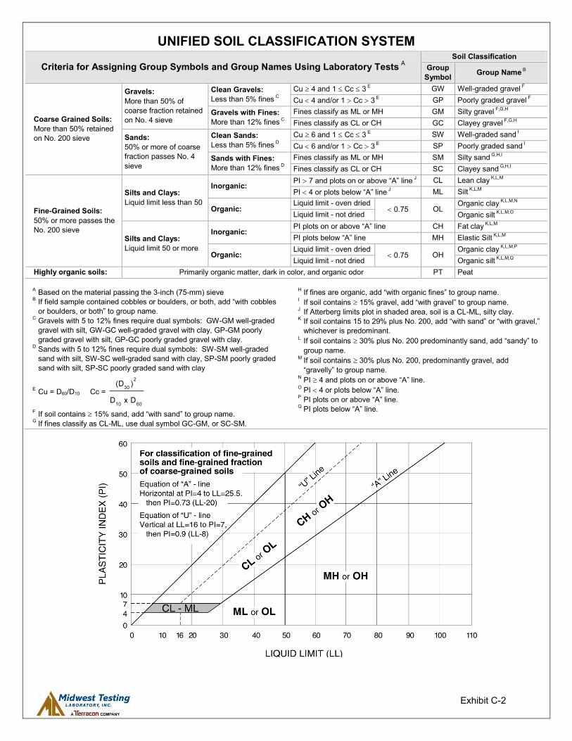
Exhibit C-2
UNIFIED SOIL CLASSIFICATION SYSTEM
Criteria for Assigning Group Symbols and Group Names Using Laboratory Tests A Soil Classification
Group Symbol Group Name B
Coarse Grained Soils: More than 50% retained on No. 200 sieve
Gravels: More than 50% of coarse fraction retained on No. 4 sieve
Clean Gravels: Less than 5% fines C
Cu 4 and 1 Cc 3 E GW Well-graded gravel F Cu 4 and/or 1 Cc 3 E GP Poorly graded gravel F
Gravels with Fines: More than 12% fines C
Fines classify as ML or MH GM Silty gravel F,G,H Fines classify as CL or CH GC Clayey gravel F,G,H
Sands: 50% or more of coarse fraction passes No. 4 sieve
Clean Sands: Less than 5% fines D
Cu 6 and 1 Cc 3 E SW Well-graded sand I Cu 6 and/or 1 Cc 3 E SP Poorly graded sand I
Sands with Fines: More than 12% fines D
Fines classify as ML or MH SM Silty sand G,H,I Fines classify as CL or CH SC Clayey sand G,H,I
Fine-Grained Soils: 50% or more passes the No. 200 sieve
Silts and Clays: Liquid limit less than 50
Inorganic: PI 7 and plots on or above “A” line J CL Lean clay K,L,M PI 4 or plots below “A” line J ML Silt K,L,M
Organic: Liquid limit - oven dried
0.75 OL Organic clay K,L,M,N
Liquid limit - not dried Organic silt K,L,M,O
Silts and Clays: Liquid limit 50 or more
Inorganic: PI plots on or above “A” line CH Fat clay K,L,M PI plots below “A” line MH Elastic Silt K,L,M
Organic: Liquid limit - oven dried
0.75 OH Organic clay K,L,M,P
Liquid limit - not dried Organic silt K,L,M,Q Highly organic soils: Primarily organic matter, dark in color, and organic odor PT Peat
A Based on the material passing the 3-inch (75-mm) sieve B If field sample contained cobbles or boulders, or both, add “with cobbles
or boulders, or both” to group name. C Gravels with 5 to 12% fines require dual symbols: GW-GM well-graded
gravel with silt, GW-GC well-graded gravel with clay, GP-GM poorly graded gravel with silt, GP-GC poorly graded gravel with clay.
D Sands with 5 to 12% fines require dual symbols: SW-SM well-graded sand with silt, SW-SC well-graded sand with clay, SP-SM poorly graded sand with silt, SP-SC poorly graded sand with clay
E Cu = D60/D10 Cc = 6010
2
30
DxD
)(D
F If soil contains 15% sand, add “with sand” to group name. G If fines classify as CL-ML, use dual symbol GC-GM, or SC-SM.
H If fines are organic, add “with organic fines” to group name. I If soil contains 15% gravel, add “with gravel” to group name. J If Atterberg limits plot in shaded area, soil is a CL-ML, silty clay. K If soil contains 15 to 29% plus No. 200, add “with sand” or “with gravel,”
whichever is predominant. L If soil contains 30% plus No. 200 predominantly sand, add “sandy” to
group name. M If soil contains 30% plus No. 200, predominantly gravel, add
“gravelly” to group name. N PI 4 and plots on or above “A” line. O PI 4 or plots below “A” line. P PI plots on or above “A” line. Q PI plots below “A” line.