geophysical proveouts for munitions response projects · geophysical prove-outs for munitions...
TRANSCRIPT

Geophysical Prove-Outsfor Munitions Response Projects
Prepared byThe Interstate Technology & Regulatory Council
Unexploded Ordnance Team
November 2004
Technical/Regulatory Guideline

ABOUT ITRC Established in 1995, the Interstate Technology & Regulatory Council (ITRC) is a state-led, national coalition of personnel from the environmental regulatory agencies of some 40 states and the District of Columbia; three federal agencies; tribes; and public and industry stakeholders. The organization is devoted to reducing barriers to, and speeding interstate deployment of, better, more cost-effective, innovative environmental techniques. ITRC operates as a committee of the Environmental Research Institute of the States (ERIS), a Section 501(c)(3) public charity that supports the Environmental Council of the States (ECOS) through its educational and research activities aimed at improving the environment in the United States and providing a forum for state environmental policy makers. More information about ITRC and its available products and services can be found on the Internet at www.itrcweb.org. DISCLAIMER This document is designed to help regulators and others develop a consistent approach to their evaluation, regulatory approval, and deployment of specific technologies at specific sites. Although the information in this document is believed to be reliable and accurate, this document and all material set forth herein are provided without warranties of any kind, either express or implied, including but not limited to warranties of the accuracy or completeness of information contained in the document. The technical implications of any information or guidance contained in this document may vary widely based on the specific facts involved and should not be used as a substitute for consultation with professional and competent advisors. Although this document attempts to address what the authors believe to be all relevant points, it is not intended to be an exhaustive treatise on the subject. Interested readers should do their own research, and a list of references may be provided as a starting point. This document does not necessarily address all applicable heath and safety risks and precautions with respect to particular materials, conditions, or procedures in specific applications of any technology. Consequently, ITRC recommends also consulting applicable standards, laws, regulations, suppliers of materials, and material safety data sheets for information concerning safety and health risks and precautions and compliance with then-applicable laws and regulations. The use of this document and the materials set forth herein is at the user’s own risk. ECOS, ERIS, and ITRC shall not be liable for any direct, indirect, incidental, special, consequential, or punitive damages arising out of the use of any information, apparatus, method, or process discussed in this document. This document may be revised or withdrawn at any time without prior notice. ECOS, ERIS, and ITRC do not endorse the use of, nor do they attempt to determine the merits of, any specific technology or technology provider through publication of this guidance document or any other ITRC document. The type of work described in this document should be performed by trained professionals, and federal, state, and municipal laws should be consulted. ECOS, ERIS, and ITRC shall not be liable in the event of any conflict between this guidance document and such laws, regulations, and/or ordinances. Mention of trade names or commercial products does not constitute endorsement or recommendation of use by ECOS, ERIS, or ITRC.

Geophysical Prove-Outs for Munitions Response Projects
November 2004
Prepared by The Interstate Technology & Regulatory Council
Unexploded Ordnance Team
Copyright 2004 Interstate Technology & Regulatory Council

Permission is granted to refer to or quote from this publication with the customary acknowledgment of the source. The suggested citation for this document is as follows: ITRC (Interstate Technology & Regulatory Council). 2004. Geophysical Prove-Outs for
Munitions Response Projects. UXO-3. Washington, D.C.: Interstate Technology & Regulatory Council, Unexploded Ordnance Team. Available on the Internet at http://www.itrcweb.org.

ACKNOWLEDGEMENTS
The members of the Interstate Technology & Regulatory Council (ITRC) Unexploded Ordnance (UXO) Team wish to acknowledge the individuals, organizations, and agencies that contributed to this technical and regulatory guidance document. As part of the broader ITRC effort, the Unexploded Ordnance Team effort is funded primarily by the U.S. Department of Energy. Additional funding and support has been provided by the U.S. Department of Defense and the U.S. Environmental Protection Agency. ITRC operates as a committee of the Environmental Research Institute of the States (ERIS), a Section 501(c)(3) public charity that supports the Environmental Council of the States (ECOS) through its educational and research activities aimed at improving the environment in the United States and providing a forum for state environmental policy makers. The team recognizes the following states’ support of team leadership and guidance document preparation: • Jeff Swanson, Colorado Department of Public Health & Environment, Team Co-Leader • Gary Moulder, Pennsylvania Department of Environmental, Team Co-Leader • Richard Albright, District of Columbia Department of Health • Kera Bell, Texas Commission on Environmental Quality • Rizgar Ghazi, California Department of Toxic Substances Control • David Larsen, Utah Department of Environmental Quality • David Lawson, Oklahoma Department of Environmental Quality • Christopher Maurer, State of Washington Department of Ecology • Ramon Naranjo, Nevada Division of Environmental Protection • Jennifer Roberts, Alaska Department of Environmental Conservation • Nicole Sotak, California Department of Toxic Substances Control • Philip Stroud, Alabama Department of Environmental Management • Ken Vogler, Colorado Department of Public Health and Environment • John Waldrip, Utah Department of Environmental Quality • Julie Wanslow, New Mexico Environment Department • Greg Zalaskus, New Jersey Department of Environmental Protection The UXO Team would also like to especially thank the following federal, military, industry and consulting personnel who provided significant contributions to this document: Brian Ambrose, Dupont; Anne Andrews, SERDP/ESTCP; Sue Gray, Sky Research, Inc.; Dwight Hempel, Bureau of the Interior; Jacqui Hood, Army Environmental Center; Aimee Houghton, Center for Public and Environmental Oversight; Norell Lantzer; Richard Mach, Naval Facilities Engineering Command; Doug Maddox, Environmental Protection Agency; Doug Murray, Naval Ordnance Safety and Security Activity; Kevin Oates, Environmental Protection Agency; Jim Pastorick, Geophex UXO; George Robitaille, Army Environmental Center; Andy Schwarz, Army Corps of Engineers; Bill Veith, Army Corps of Engineers; and Laura Wrench, Versar. Thanks also to Stacey Kingsbury, ITRC Program Advisor, for urging progress during the development of the guidance and providing assistance to the team.
i

EXECUTIVE SUMMARY
Geophysical systems are integral to munitions response efforts because they detect surface and subsurface anomalies such as unexploded ordnance and discarded military munitions during geophysical surveys at munition response sites. Detection of munitions and explosives of concern is critical to the success of the overall munitions response effort because items that are not detected will not be removed. Before conducting a geophysical survey of an entire munitions response site, a site-specific geophysical prove-out (GPO) is conducted to test, evaluate, and demonstrate these geophysical systems. Information collected during the prove-out is analyzed and used to select or confirm the selection of a geophysical system that can meet the performance requirements established for the geophysical survey. This document introduces the purpose and scope of GPOs, provides examples of goals and objectives associated with GPOs, and presents detailed information needed to understand and evaluate the design, construction, implementation and reporting of GPOs. This document also communicates the expectations of state regulators to those designing, executing, and reporting GPOs. Because not everyone who will need or want to evaluate a GPO has a background in geophysics, this document includes a background chapter on geophysical surveys as conducted during the course of munitions response actions.
iii

TABLE OF CONTENTS
ACKNOWLEDGEMENTS............................................................................................................. i
EXECUTIVE SUMMARY ........................................................................................................... iii
1. INTRODUCTION .....................................................................................................................1 1.1 State Regulator Role in GPOs .......................................................................................... 1 1.2 Geophysics in Munitions Response.................................................................................. 2 1.3 Definitions ........................................................................................................................ 3 1.4 Document Organization and How to Use this Document ................................................ 6
2. INTRODUCTION TO GEOPHYSICAL SURVEYS...............................................................7 2.1 Geophysics and Geophysical Equipment ......................................................................... 7 2.2 Geophysical Survey Process............................................................................................. 9 2.3 Geophysical Survey Tools and Equipment .................................................................... 13 2.4 Geophysical Survey Results and Outcome..................................................................... 23
3. GPO GOALS AND OBJECTIVES.........................................................................................23
4. GPO TECHNICAL PROCESS INTRODUCTION ................................................................25 4.1 GPO Design.................................................................................................................... 26 4.2 GPO Construction .......................................................................................................... 32 4.3 GPO Implementation...................................................................................................... 34 4.4 GPO Reporting ............................................................................................................... 36
5. DATA QUALITY OBJECTIVES AND PERFORMANCE METRICS.................................38 5.1 Data Quality Objectives ................................................................................................. 38 5.2 Performance Metrics ...................................................................................................... 39 5.3 Quality Control Tests ..................................................................................................... 44
6. ISSUES, CONCERNS, AND RECOMMENDATIONS.........................................................45 6.1 Design Phase Considerations ......................................................................................... 45 6.2 Construction Phase Considerations ................................................................................ 51 6.3 Implementation and Reporting ....................................................................................... 53 6.4 Reporting and Review Considerations ........................................................................... 55
7. REFERENCES ........................................................................................................................56 7.1 Documents...................................................................................................................... 56 7.2 Internet Sites ................................................................................................................... 57
LIST OF TABLES
Table 2-1. Comparison of detection technologies for geophysical surveys..................................15 Table 4-1. Basic site-specific GPO criteria ...................................................................................27 Table 4-2. GPO work plan elements .............................................................................................31 Table 5-1. Sample GPO DQOs .....................................................................................................40
v

LIST OF FIGURES Figure 2-1. Mag and flag survey....................................................................................................8 Figure 2-2. Flags marking selected anomalies following a mag and flag survey..........................8 Figure 2-3. Typical dig sheet information .....................................................................................9 Figure 2-4. Geophysical survey process......................................................................................10 Figure 2-5. Handheld magnetometer ...........................................................................................17 Figure 2-6. Handheld electromagnetic detector...........................................................................17 Figure 2-7. Cart-mounted magnetometer ....................................................................................18 Figure 2-8. Cart-mounted EM .....................................................................................................18 Figure 2-9. Towed sensor array ...................................................................................................18 Figure 2-10. Helicopter-based survey............................................................................................19 Figure 2-11. Airborne survey ........................................................................................................19 Figure 2-12. Geophysical survey coverage schemes.....................................................................20 Figure 2-13. Ropes-and-lanes navigation in a geophysical survey area........................................22 Figure 4-1. GPO technical process ..............................................................................................26 Figure 4-2. GPO seed item emplacement ....................................................................................33 Figure 5-1. ROC curve ................................................................................................................43
APPENDICES APPENDIX A. Acronyms and Abbreviations APPENDIX B. Dig Sheets APPENDIX C. Geophysical Maps APPENDIX D. UXO Team Contacts, ITRC Fact Sheet and Product List
vi

GEOPHYSICAL PROVE-OUTS FOR MUNITIONS RESPONSE PROJECTS 1. INTRODUCTION
The fundamental goal of a geophysical prove-out (GPO) is to determine whether a particular geophysical investigation approach will provide satisfactory results for a munitions response (MR) action on a munitions response site (MRS). The GPO process tests, evaluates, and demonstrates the site-specific capabilities of one or several geophysical systems under consideration for an MR action. GPO results are used to help select or confirm the capabilities of the most appropriate technology. This document provides the following guidance regarding the role and use of site-specific GPOs: • background information on geophysical surveys and equipment; • explanations of the purpose, scope, content, and terminology of GPOs; • technical guidance for reviewing the design, execution, and reporting of GPOs; and • the means to communicate the expectations of state regulators to those designing, executing,
and reporting GPOs. This document is designed primarily for state1 regulators who may not be familiar with geophysical surveys and/or GPOs. Therefore, this document begins with introductory and background information on the context of the GPO in the munitions response process. The document then goes into detail regarding the GPO technical process. Last, it provides a frequently asked questions–style chapter to facilitate discussion and answer questions likely to occur during the different phases of the GPO process. Regardless of the level of familiarity with GPOs, this document will be useful to all members of the munitions response community and stakeholders in the munitions response process. 1.1 State Regulator Role in GPOs
The state may be the lead regulator for environmental investigations and response pertaining to munitions response actions on other than operational ranges, including Formerly Used Defense Sites (FUDS) and Base Realignment and Closure (BRAC) sites. This document focuses on one technical aspect of the munitions response process—the GPO conducted prior to a geophysical survey of an MRS. During the GPO process, a state regulator with oversight authority should • understand the purpose and limitations of GPOs in general; • evaluate whether or not the goals and objectives of a GPO are appropriate for the planned
geophysical survey; • understand GPO-related performance metrics and how they are determined; • perform field oversight to ensure the GPO construction and implementation are as consistent
as possible with the sampling design as documented in the work plan;
1 Throughout this document, the term “state” is used to refer to all regulatory entities having the general regulatory responsibilities of the states, including U.S. territories and commonwealths.

ITRC – Geophysical Prove-Outs for Munitions Response Projects November 2004
• evaluate whether or not the quality assurance/quality control (QA/QC) protocol established for the GPO has been followed;
• review the GPO report for completeness; and • evaluate whether or not the GPO objectives have been achieved and documented. By providing this information, this document will assist state regulators and others communicate with U.S. Department of Defense (DoD) staff and their contractors regarding munitions response actions. Furthermore, state participation in the GPO process will help to facilitate regulatory acceptance of munitions response actions and results. 1.2 Geophysics in Munitions Response
Geophysical systems are integral to MR efforts because it is these systems that detect potential munitions and explosives of concern (MEC), i.e., unexploded ordnance (UXO) and discarded military munitions (DMM)2 present at an MRS. Detection of MEC is critical to the success of the overall munitions response because items that are not detected will not be removed. Therefore, Chapter 2 of this document provides an overview of the geophysical systems and methods typically used for geophysical surveys. Please note that this document focuses primarily on detecting MEC for munitions response; categorizing MEC (i.e., munition type) is still a focus of research and development efforts and is currently possible in only extremely limited conditions. The system or systems selected to conduct the geophysical survey of an MRS must be able to detect the munitions items expected to be present on the site. Demonstrations of this capability take place on both standardized test sites and on MRSs during GPOs. Standardized test sites are used to evaluate the capability of geophysical systems under controlled conditions. To meet these broad testing needs, the U.S. Army established the Standardized UXO Technology Demonstration Site Program. The U.S. Army Environmental Center (USAEC) spearheads this multiagency program, which is funded and supported by the Environmental Security Technology Certification Program (ESTCP), the Strategic Environmental Research and Development Program (SERDP), and the Army Environmental Quality Technology (EQT) program. This program provides geophysical sensor technology users and developers with two standardized sites—encompassing flat, uneven, open, and forested settings—to define the range of applicability of specific technologies, gather data on sensor and system performance, compare results, and document real-life cost and performance information.3 Standardized test site information provides valuable guidance about basic technological capabilities of geophysical systems, but this information is not sufficient for making site-specific decisions.
2Unexploded ordnance and discarded military munitions are subsets of munitions and explosives of concern. This document refers to UXO and DMM as MEC. 3 For more information on the Standardized UXO Technology Demonstration Site Program, see the program’s Web page at http://www.uxotestsites.org.
2

ITRC – Geophysical Prove-Outs for Munitions Response Projects November 2004
Because demonstrating the ability of a geophysical system to detect an item under ideal conditions alone is not enough, the detection threshold of a geophysical system under consideration for a geophysical survey must be clearly established and documented under the actual field conditions to be encountered at the MRS. The geophysical system must also be capable of distinguishing the item of interest from background noise and of identifying or selecting the item’s signature within the raw data as an anomaly. Site-specific conditions—such as the types of munitions present, depth of interest, soil composition, vegetation, terrain, and cultural interferences—influence the effectiveness of geophysical surveys, often in unpredictable ways. For many MRSs, multiple geophysical systems and approaches could potentially be used to detect surface and subsurface anomalies (i.e., MEC). Because all geophysical approaches have inherent strengths and weaknesses, very seldom does one instrument or approach have the best performance in all measurable categories. Therefore, the GPO is a vital step in evaluating the strengths and weaknesses of each geophysical system under consideration.
What is an anomaly? In general, an anomaly is any response above the noise threshold that merits further investigation. This document uses “anomaly” to mean a subsurface feature detected by a geophysical instrument that warrants further investigation.
On large sites, more than one GPO may be required. For example, widely differing terrain, geology, or weapons systems may require multiple prove-out locations to gather representative information for varying site conditions unless a single prove-out area can be established that incorporates these differing site characteristics. Other reasons for performing more than one GPO can include multiple field seasons where remobilization and reestablishment of prove-out parameters are required, new information about site conditions that causes revisions to conceptual site models and geophysical methods (e.g., changing geophysical sensors), or nonconformance problems that require reevaluation of equipment and/or process team elements. 1.3 Definitions
The terminology used in munitions response has evolved over the years. In 2003, DoD established the following standardized terminology for its Military Munitions Response Program (MMRP)(DoD 2003): • defense sites—locations that are or were owned by, leased to, or otherwise possessed or used
by the Department of Defense. The term does not include any operational range, operating storage or manufacturing facility, or facility that is used for or was permitted for the treatment or disposal of military munitions (10 U.S.C. 2710[e][1]).
• discarded military munitions (DMM)—military munitions that have been abandoned without
proper disposal or removed from storage in a military magazine or other storage area for the purpose of disposal. The term does not include unexploded ordnance, military munitions that are being held for future use or planned disposal, or military munitions that have been properly disposed of consistent with applicable environmental laws and regulations (10 U.S.C. 2710[e][2]).
3
ITRC – Geophysical Prove-Outs for Munitions Response Projects November 2004
• explosives or munitions emergency response—all immediate response activities by an explosives and munitions emergency response specialist to control, mitigate, or eliminate the actual or potential threat encountered during an explosives or munitions emergency. An explosives or munitions emergency response may include in-place render-safe procedures, treatment or destruction of the explosives or munitions, and/or transporting those items to another location to be rendered safe, treated, or destroyed. Any reasonable delay in the completion of an explosives or munitions emergency response caused by a necessary, unforeseen, or uncontrollable circumstance will not terminate the explosives or munitions emergency. Explosives and munitions emergency responses can occur on either public or private lands and are not limited to responses at RCRA [Resource Conservation and Recovery Act] facilities (Military Munitions Rule, 40 CFR 260.10).
• munitions constituents (MC)—any materials originating from unexploded ordnance,
discarded military munitions, or other military munitions, including explosive and nonexplosive materials, and emission, degradation, or breakdown elements of such ordnance or munitions (10 U.S.C. 2710 [e][4]).
• munitions and explosives of concern (MEC)—this term, which distinguishes specific
categories of military munitions that may pose unique explosives safety risks, means (A) UXO, as defined in 10 U.S.C. 2710 (e)(9); (B) discarded military munitions (DMM), as defined in 10 U.S.C. 2710 (e)(2); or (C) explosive munitions constituents (e.g., TNT, RDX) present in high enough concentrations to pose an explosive hazard.
• munitions response (MR)—response actions, including investigation, removal, and remedial
actions to address the explosives safety, human health, or environmental risks presented by unexploded ordnance (UXO), discarded military munitions (DMM), or munitions constituents (MC).
• munitions response area (MRA)—any area on a defense site that is known or suspected to
contain UXO, DMM, or MC. Examples include former ranges and munitions burial areas. An MRA comprises one or more munitions response sites.
• munitions response site (MRS)—a discrete location within a MRA that is known to require a
munitions response.
4

ITRC – Geophysical Prove-Outs for Munitions Response Projects November 2004
• military munitions4—military munitions means all ammunition products and components produced for or used by the armed forces for national defense and security, including ammunition products or components under the control of the Department of Defense, the Coast Guard, the Department of Energy, and the National Guard. The term includes confined gaseous, liquid, and solid propellants, explosives, pyrotechnics, chemical and riot control agents, smokes and incendiaries, including bulk explosives and chemical warfare agents, chemical munitions, rockets, guided and ballistic missiles, bombs, warheads, mortar rounds, artillery ammunition, small arms ammunition, grenades, mines, torpedoes, depth charges, cluster munitions and dispensers, demolition charges, and devices and components thereof.
The term does not include wholly inert items, improvised explosive devices, and nuclear weapons, nuclear devices, and nuclear components, other than nonnuclear components of nuclear devices that are managed under the nuclear weapons program of the Department of Energy after all required sanitization operations under the Atomic Energy Act of 1954 (42 U.S.C. 2011 et seq.) have been completed (10 U.S.C. 101(e)(4).
• operational range—a range that is under the jurisdiction, custody, or control of the Secretary
of Defense and (A) that is used for range activities or (B) although not currently being used for range activities, that is still considered by the Secretary to be a range and has not been put to a new use that is incompatible with range activities (10 U.S.C. 101 [e][3]).
• range—the term “range,” when used in a geographic sense, means a designated land or water
area that is set aside, managed, and used for range activities of the Department of Defense. Such term includes the following: (A) Firing lines and positions, maneuver areas, firing lanes, test pads, detonation pads, impact areas, electronic scoring sites, buffer zones with restricted access, and exclusionary areas. (B) Airspace areas designated for military use in accordance with regulations and procedures prescribed by the Administrator of the Federal Aviation Administration (10 U.S.C. 101[e][3]).
• unexploded ordnance (UXO)—military munitions that (A) have been primed, fused, armed,
or otherwise prepared for action; (B) have been fired, dropped, launched, projected, or placed in such a manner as to constitute a hazard to operations, installations, personnel, or material; and (C) remain unexploded whether by malfunction, design, or any other cause (10 U.S.C. 101 [e][5]).
4 Military munitions is also defined by federal regulation; 40 CFR 260.10 defines “military munitions” as all ammunition products and components produced or used by or for the U.S. Department of Defense or the U.S. Armed Services for national defense and security, including military munitions under the control of the Department of Defense, the U.S. Coast Guard, the U.S. Department of Energy (DOE), and National Guard personnel. The term “military munitions” includes confined gaseous, liquid, and solid propellants, explosives, pyrotechnics, chemical and riot control agents, smokes, and incendiaries used by DoD components, including bulk explosives and chemical warfare agents, chemical munitions, rockets, guided and ballistic missiles, bombs, warheads, mortar rounds, artillery ammunition, small-arms ammunition, grenades, mines, torpedoes, depth charges, cluster munitions and dispensers, demolition charges, and devices and components thereof. Military munitions do not include wholly inert items, improvised explosive devices, and nuclear weapons, nuclear devices, and nuclear components thereof. However, the term does include nonnuclear components of nuclear devices, managed under DOE’s nuclear weapons program after all required sanitization operations under the Atomic Energy Act of 1954, as amended, have been completed.
5

ITRC – Geophysical Prove-Outs for Munitions Response Projects November 2004
Readers of this and other documents concerning munitions response should be aware that they will see other terminology related to munitions response. The most likely term that will be encountered is “ordnance and explosives” (OE), which has been officially replaced by “MEC” and has essentially the same meaning. 1.4 Document Organization and How to Use this Document
This document has been organized for use as both guidance and reference. Consequently, it provides information not only on GPOs, but also on the broader topics of geophysical surveys, equipment, and methodologies currently used in munitions response actions. This broader topic information is provided to give the reader the background necessary to understand the context of GPOs in munitions response actions. This document is not necessarily intended to be read cover to cover. Instead, the reader is encouraged to explore the document and focus on those chapters and topics of specific interest or relevance. • Chapter 1 provides the basic introduction to this document and geophysical prove-outs, as
well as current MR terminology. • Chapter 2 provides an introduction to geophysics and geophysical technology, equipment,
and techniques currently used for munitions response actions. It is recommended that those not familiar with UXO geophysics read Chapter 2 because it provides the basic background information needed by anyone participating in the review and evaluation of a GPO plan or report. Readers of this document already familiar with geophysics used in munitions response may find a brief review this chapter adequate.
• Chapter 3 is an introduction to the goals of GPOs and provides several examples of GPO
objectives and the influence of the objectives on the GPO design. • Chapter 4 is an introduction to the GPO technical process. It introduces each of the following
major steps in the GPO process: - Design—encompassing the development of GPO objectives, site location selection, GPO
design, and work plan development - Construction—preparing the site, followed by burying (seeding) of items to be detected
in the test plot - Implementation—testing of candidate geophysical systems in accordance with the work
plan, including reacquisition and evaluation - Reporting—documenting the performance of the instrument(s) used in the GPO, survey
maps, anomaly maps, and dig sheets. • Chapter 5 is intended as an encyclopedic reference covering GPO data quality objectives
(DQOs) and performance metrics. Specifically, it explains how objectives are established for a GPO, the importance of data quality, and the calculation and application of example GPO performance measures. It is critical that project goals and objectives be identified before
6

ITRC – Geophysical Prove-Outs for Munitions Response Projects November 2004
undertaking a GPO. These goals and objectives may vary dependent on whether the project in question is an investigation, a removal, or a remedial action.
• Chapter 6 covers specific issues, concerns, and recommendations for each major step of a
GPO. It is presented in a question-and-answer format to assist state regulators in facilitating dialogue and communicating expectations for a planned GPO and assessing the adequacy of completed GPOs.
2. INTRODUCTION TO GEOPHYSICAL SURVEYS
Geophysics involves the application of physical theories and measurements to discover the properties of the earth. Geophysical surveys are typically noninvasive investigations of the earth’s surface and subsurface involving the measuring, analyzing, and interpreting of physical fields. While some studies can extend to depths of tens of meters or more below ground surface (bgs), geophysical surveys for MR actions are used to investigate the near subsurface (the upper meter or so). Geophysical surveys for MR actions utilize the equipment, personnel, and procedures necessary to detect subsurface anomalies in a nonintrusive manner. If buried military munitions can be confidently and efficiently located, excavation is a relatively straightforward process. However, if the geophysical investigation process is not adequate, then one of two things may happen as a result: some of the military munitions will not be detected and will be left in the ground or items that are not military munitions will be detected but not properly identified, resulting in unnecessary excavations. 2.1 Geophysics and Geophysical Equipment
For MR efforts, the selection of the equipment, personnel, and procedures used to detect and locate anomalies greatly affects the efficiency and effectiveness of the geophysical survey.
Effectiveness—The degree to which the geophysical process meets or exceeds the needs and requirements of the stakeholders (owner, client, regulator and public). It answers the question, “How well does the geophysical system perform?” Efficiency—The degree of effectiveness of the process compared to the resources used. Optimizing efficiency leads to customer satisfaction by minimizing time and cost and maximizing value. It answers the question, “How long does it take and how much does it cost ?”
Geophysical detection and positioning methods range from basic to more complex. The simplest methods utilize handheld instruments that alert the operator to anomalies with a visible or audio signal. The operator records the anomaly location with a pin and flag. This method is commonly referred to as “mag and flag.” More sophisticated devices acquire geophysical data using self-recording instruments. The data is post-processed to identify anomalies for further investigation. This method is called digital geophysical mapping (DGM). The methodology selected should ultimately be the one that will meet the performance objectives for the response action and should be able to detect the items of interest to specified depths. Because there are relatively wide variances in both the capabilities and cost in currently available geophysical
7

ITRC – Geophysical Prove-Outs for Munitions Response Projects November 2004
investigation technologies and procedures, trade-offs between effectiveness and efficiency may be necessary. These trade-offs should be understood and explicitly incorporated into the decision-making process as necessary. 2.1.1 Mag and Flag Method
For analog mag and flag surveys, UXO personnel survey the area with geophysical sensors and manually interpret anomalies and surface-mark them with nonmetallic flags for excavation (Figures 2-1 and 2-2). A summary of the excavation results (often referred to as a “dig sheet”) is produced for the area as is documentation of quality control results.
Figure 2-2. Flags marking selected anomalies following a mag and flag survey.
Figure 2-1. Mag and flag survey.
Mag and flag surveys may be the most appropriate option, or even the only option, for conducting a geophysical survey, especially where high MEC density, high magnetic noise, and/or access may be issues. In addition, there is a low capital cost for equipment associated with this methodology. However, there are several disadvantages in using mag and flag surveys: the process is difficult to QC (i.e., to measure the ability of the technician to interpret the geophysical instrument’s signal); the tools most commonly used are significantly less sensitive to the physical parameters being measured than most digital geophysical equipment; it is impossible to verify that the entire search was covered by the geophysical sensor operators; and last, no direct record of geophysical data or the decision-making process is produced. 2.1.2 Digital Geophysical Mapping Methods
As a result of advances in geophysical sensors, field techniques, and global positioning systems (GPS), the use of digital geophysical methods for geophysical surveys has become more widespread for MR projects. Using DGM methods, the ground is “mapped” by correlating sensor data points with GPS coordinates. The survey data from the geophysical survey is processed and analyzed, and anomalies within the data are selected. As a result, a dig sheets are compiled that record the anomalies selected for excavation (Figure 2-3). After excavation, the dig sheets also show the results of those excavations. The dig sheets and the electronic records of geophysical and positioning data should be archived and available for data quality review.
8

ITRC – Geophysical Prove-Outs for Munitions Response Projects November 2004
This methodology represents an improvement over mag and flag methods because of the improved ability not only to locate anomalies but to locate them to a greater depth and, in some limited circumstances, the ability to characterize a buried item as MEC or non-MEC.5
Figure 2-3. Typical dig sheet information.
2.2 Geophysical Survey Process
This section is intended as a general overview of a complex, and at times highly technical, geophysical survey process. For more detailed information regarding the overall geophysical survey process, refer to Chapter 7 of Ordnance and Explosives Response (USACE 2000b). The geophysical survey process for munitions response actions consists of a series of steps. This document breaks this process into nine possible steps—from defining the survey area, to selecting and deploying the survey equipment, to reporting the results (Figure 2-4). The actual number and sequence of steps in this process varies from site to site and depends on the type of geophysical survey conducted (mag and flag or DGM) and whether a GPO is needed to select the equipment to be used in the survey. 2.2.1 Define Survey Area
The geophysical investigation area will have been previously identified in the conceptual site model (CSM) as the area where potential munitions contamination is to be investigated. During the course of the geophysical investigation, the CSM and geophysical investigation area may be further refined based on geophysical survey results. A professional land survey is typically conducted to delineate the boundaries of the investigation area before the geophysical survey is conducted. 5 Target size and depth can be reliably recovered from magnetometer data for single items. On sites with limited munitions types with low to moderate densities where isolated signatures can be measured, cultural and munitions debris can be screened reliably from military munitions.
9

ITRC – Geophysical Prove-Outs for Munitions Response Projects November 2004
Figure 2-4. Geophysical survey process. A GPO may be conducted to test equipment and, if necessary, to select equipment.
2.2.2 Select Sampling Design
The determination of the survey approach (mag and flag or DGM) is a critical component of the sampling design. Sampling design is influenced by the phase of the response action (i.e., site inspection, detailed investigation, or cleanup action), the overall goals and objectives for that response action, the type of military munitions expected to be found, and the terrain and vegetation of the site. Therefore, these goals and objectives need to be defined and documented before beginning the sampling design. The sampling design includes the general types of equipment, methods, and personnel to be used in the geophysical survey. The equipment design includes the type of sensor, deployment platform, positioning and navigational equipment, and data processing systems to be used in the survey. The methodology includes the type of survey coverage scheme and minimum data
10
ITRC – Geophysical Prove-Outs for Munitions Response Projects November 2004
collection parameters to be used in the survey. The equipment and methodology will be dictated largely by the type and size of munitions of concern, the site’s terrain, and specific project DQOs. 2.2.3 Select Equipment
The sampling design process may have already identified the equipment to be used for the geophysical survey. If not, a GPO can be used to select the equipment to be used for the survey. In some cases, several different types of equipment can be expected to meet the sampling design criteria. In this situation, a GPO designed as a competitive field demonstration may not be needed but may be helpful in selecting the equipment that will most efficiently meet the design criteria. In other cases, the types of equipment that could meet the design criteria may not be known, especially at sites with challenging conditions. In this situation, several types of equipment may be evaluated to determine which has the best chance of successfully meeting the survey goals, objectives, and specific DQOs. In either case, standardized geophysical test sites results can be used to help select the equipment to be tested using a GPO (see Standardized UXO Technology Demonstration Handbook [U.S. Army Aberdeen Test Center 2002]). 2.2.4 Test Equipment (Conduct GPO)
The equipment selected to perform the geophysical investigation must be tested under site-specific conditions to determine and document its capability to meet the project’s overall goals and objectives as well as specific DQOs. A GPO determines and documents this capability. If a GPO is used to select equipment as described above, the GPO to test the equipment may be conducted concurrently. In a GPO, the survey equipment is deployed over an area representative of the proposed survey area in terms of site characteristics. The prove-out area is seeded with inert military munitions or their surrogates to determine the capabilities of the proposed survey methods to detect the military munitions expected to be found on the site. The GPO tests the entire survey process from field data collection to anomaly selection to anomaly reacquisition. The GPO process is discussed in greater detail in Chapter 4.
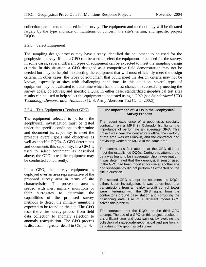
The Importance of GPOs in the Geophysical Survey Process
The recent experience of a geophysics specialty contractor on a MRS in Colorado highlights the importance of performing an adequate GPO. This project was near the contractor’s office, the geology of the area was well known, and the contractor had previously worked on MRSs in the same area. The contractor’s first attempt at the GPO did not meet the established DQOs. During this attempt, the data was found to be inadequate. Upon investigation, it was determined that the geophysical sensor used in the GPO had been modified for use at another site and subsequently did not perform as expected on the site in question. The second GPO attempt did not meet the DQOs either. Upon investigation, it was determined that transmissions from a nearby aircraft control tower were interfering with the GPS signal from the contractor’s ground base station and corrupting the positioning data. Use of a different model GPS solved this problem. The contractor met the DQOs on the third GPO attempt. The use of a GPO on this project resulted in a significant time and cost savings by avoiding the collection of inadequate geophysical and positioning data during the geophysical survey.
11
ITRC – Geophysical Prove-Outs for Munitions Response Projects November 2004
2.2.5 Prepare and Survey Site
Once the equipment has been selected and a GPO conducted to verify its performance capabilities, the survey site is prepared for the geophysical survey by conducting any necessary safety work and site preparation activities. This process typically includes a MEC surface clearance to remove any MEC potential hazards to the survey team, removal of surficial metallic objects to eliminate potential interference, vegetation clearance, and establishment of survey grids and control points. Vegetation clearance is conducted in areas where grass, brush, or trees must be removed to gain access to map the survey area. Methods of vegetation clearance can include mowing, grubbing, and controlled burns. For surveys of large areas, the site is typically gridded to create a local location reference system. During survey preparation, the grid is set in the field by placing flags, laths, steel nails, or spikes at the corners of each grid to establish survey controls for the geophysical data. After the site is prepared, the survey is conducted by deploying the selected equipment utilizing the methods and procedures defined in the geophysical survey plan. Production geophysical survey rates are site- and equipment-dependent and can vary from less than an acre per day for man-portable equipment to several tens or hundreds of acres per day for towed arrays or airborne surveys on open terrain. 2.2.6 Select Anomalies
For mag and flag projects, UXO technicians put a nonmetallic flag in the ground where anomalies are detected. For DGM surveys, the raw data is collected in the field, then further processed and analyzed by project geophysicists to develop a map of subsurface geophysical anomalies. The anomalies are then evaluated using the geophysical target selection criteria to establish a dig list. The dig list shows anomaly locations to be investigated by field UXO personnel. As a QC measure and a false negative check, a random percentage of anomalies not selected as digs may also be investigated. 2.2.7 Reacquire and Dig Anomalies
In DGM surveys, anomaly locations identified during the selection phase must be reacquired (relocated) in the field. Anomaly locations are sent to the field as coordinates on the dig sheet. The exact coordinates are then reacquired. A search radius based on positioning system accuracy is established around each coordinate. Within the search radius, handheld detectors are used to pinpoint specific anomalies for excavation. It is not uncommon to find multiple discrete anomalies within a search radius. In mag and flag surveys, anomaly locations are identified in real time with a flag and therefore do not have to be reacquired. Regardless of the type of survey conducted, each anomaly is excavated. The amount of data collected during the digs is dependent on the survey goals, objectives, and specific DQOs. The amount of data can also vary greatly depending on the phase of the response action (i.e., site inspection, detailed investigation, or cleanup action).
12

ITRC – Geophysical Prove-Outs for Munitions Response Projects November 2004
At this step, potentially hazardous excavated items are either destroyed in situ (known as “blown in place,” or “BIP”) or removed from the immediate area to be destroyed with other recovered remnants. Nonhazardous munitions scrap is processed for disposal, while cultural debris (nails, fence wire, horseshoes, etc.) is removed. After excavation of the anomalies, the area is rescreened with the handheld instrument(s) to ensure that no items have been missed. Each dig location is checked and verified in the field to ensure that all potential anomalies are located, dug, and investigated. 2.2.8 Conduct Quality Assurance/Quality Control
Standard, accepted QA/QC procedures that are applicable to other deliverable products are applicable to the process of geophysical surveys for munitions response. Traditionally, the person, company, or organization performing the work performs QC to ensure that the performed work meets internal or contractual standards for quality. The party accepting the work usually performs the QA to verify that the required quality standards have been achieved. DGM surveys require additional QA/QC measures. For example, daily sensor function checks should be conducted before data collection begins. Also, the dig results are sent to the project geophysicist to evaluate the target anomaly signature against the items removed from the location. In some instances, the geophysical mapping equipment is also deployed to remap areas and/or individual anomalies and verify removals and the resulting data checked to make sure it meets specifications. There are additional QC/QA measures throughout the geophysical survey process not specifically mentioned in this summary. Specific QC procedures are required when anomaly resolution decisions use instruments that differ from those used to initially select the anomalies. Regardless of the type of survey performed, the DQOs for the survey are reviewed against the survey results to verify that the survey has met its objectives and quality standards. 2.2.9 Verify and Report the Results
The final step in the process is to verify the process and report the results. Again, the level of verification and reporting depend on the type of survey, its overall goals and objectives, and the DQOs. At this step, the results of the survey are compiled, achievement of DQOs is documented, data files are compiled for final submission, and a final survey report is prepared. 2.3 Geophysical Survey Tools and Equipment
A geophysical survey system for either mag and flag or DGM is composed of four main elements: the geophysical sensor, survey platform, positioning system, and data processing system. These elements are discussed below in general and in more detail in the following subsections. With its central role in detecting anomalies, the geophysical sensor is generally the main focus in equipment selection. However, the three remaining elements are also critical to the success of the overall geophysical system. The survey platform deploys the geophysical sensor and not only governs the terrain in which the system can be operated, but is also a major factor in system and
13

ITRC – Geophysical Prove-Outs for Munitions Response Projects November 2004
motion noise, as well. The positioning equipment determines the geophysical sensor’s geographic location at each data point recorded during the survey. The data processing system ultimately determines how data is handled and how targets are selected and interpreted. For mag and flag surveys, these elements are inherent to the survey method—the UXO technician holding the sensor is both the survey platform and the data processing system. For DGM surveys, the elements are usually more complex, and many are integrated into the mapping system. 2.3.1 Geophysical Sensors
There are currently two types of geophysical sensors commonly used at most munitions response sites: magnetometers (mag) and electromagnetic induction (EMI) devices. These sensors are well characterized and broadly accepted by the industry. Ground-penetrating radar (GPR) instruments have also been used but have a very limited applicability for munitions response. These technologies are all nonintrusive tools to identify subsurface anomalies, including those that may be caused by subsurface MEC. Table 2-1 summarizes the capabilities and limitations for each method. • Magnetometers. Magnetometry is the science of measurement and interpretation of magnetic
fields. Magnetometers locate buried munitions by detecting irregularities in the earth’s magnetic field caused by the ferromagnetic materials in munitions. Magnetometers are passive devices and respond to ferrous materials, such as iron, steel, and brass. Magnetometers do not respond to metals that are not ferromagnetic, such as copper, tin, and aluminum. Typically these sensors perform better for large, deep, ferrous objects. They may also detect small ferrous objects at or near the surface better than electromagnetic sensors with large sensor coils.
Fluxgate magnetometers are typically the type of magnetometers used for mag and flag surveys, although a wide variety of handheld digital and analog magnetometers can be used. Typically inexpensive and easy to operate, fluxgate magnetometers are also used for anomaly reacquisition. Although many fluxgate magnetometers do not digitally record data, data loggers can be adapted to be used with this type of magnetometer. One disadvantage of this type of magnetometer is that it must be leveled to provide accurate measurements. Also, it typically has a higher noise floor than other instruments.
Another type of magnetometer used for mag and flag surveys is the cesium vapor magnetometer. Lightweight and portable, the principal advantage of cesium vapor magnetometers is their rapid data collection capability. One disadvantage of this type of magnetometer is that it is insensitive to the magnetic field in certain directions. Also, dropouts can occur where the magnetic field is not measured; however, this problem can be avoided with proper field procedures.
14

ITRC – Geophysical Prove-Outs for Munitions Response Projects November 2004
Table 2-1. Comparison of detection technologies for geophysical surveys Technology Description Capabilities Limitations
Magnetometry Magnetometry locates buried military munitions by detecting irregularities in the earth’s magnetic field caused by materials in munitions. This is a completely passive system that emits no electromagnetic (EM) radiation.
• Can detect larger ferrous objects at deeper depths than EMI methods.
• Can detect small ferrous objects at or near the surface better than EM sensors with large sensor coils.
• Multiple systems can be linked together in an array to enhance production rates and increase efficiency.
• Data can be analyzed to estimate target size and depth.
• Detects only ferrous materials. • Influenced by high
concentrations of surface munitions fragments, background magnetic noise, and site-specific soil properties.
• Commonly used magnetometers are less sensitive than most EM sensors.
• Instrument response may be affected by nearby power lines and cultural features.
Electromagnetic induction
EMI systems induce an electromagnetic field and measure the response of objects near the sensor. These systems measure the secondary magnetic field induced in metal objects either in the time domain or frequency domain. Conductive objects such as UXO have very different EM properties from soils.
• Detects both ferrous and nonferrous metallic objects.
• Advanced systems have multiple frequency and time gates.
• Additional data can provide information on target shape, orientation, and material properties.
• Multiple sensors can be linked together in an array to enhance production rates and increase efficiency.
• EM systems are less susceptible to cultural noise sources, such as utilities, fences, etc. than magnetic methods.
• Influenced by high concentrations of surface munitions fragments.
• Limited depth of investigation because the signal falls off with distance—1/R6 vs. 1/R3 for magnetometry. EM radiation may be a hazard around electrosensitive munitions, particularly certain fuzes.
• Limited by vegetation and steep terrain.
• Although less susceptible to cultural noise, EM systems may still be affected by nearby power lines and cultural features in close proximity to the sensor.
Ground-penetrating radar
GPR systems transmit short pulses of electromagnetic energy into the ground; buried objects reflect the signals back to the receiving unit, where they are recorded and may be processed into an image.
• GPR responds to both ferrous and nonferrous materials.
• Multiple systems can be linked together in an array to enhance production rates and increase efficiency.
• Extremely site specific with minimal applicability to MRSs; generally not recommended for most sites.
• Performance is severely degraded by conductive and metallic soils.
• Saturated soils can attenuate signal response.
• Limited by vegetation and steep terrain.
• Can be computationally intensive.
• Susceptible to clutter from a wide variety of sources.
15

ITRC – Geophysical Prove-Outs for Munitions Response Projects November 2004
• Electromagnetic Induction. EMI is a geophysical technology used to transmit an
electromagnetic field beneath the earth’s surface, which in turn induces a secondary magnetic field around objects (ferrous and nonferrous metallic materials) that have conductive properties. When secondary magnetic fields of military munitions and other conductive items exceed background responses, they can be identified as potential anomalies requiring further investigation.
There are two basic modes of EMI operation: frequency domain and time domain. Frequency-domain electromagnetic (FDEM) systems measure the response of the subsurface as a function of frequency. These systems are used for MEC detection and discrimination; some have also been used for detecting boundaries of trenches that may be MEC disposal sites. Time-domain electromagnetic (TDEM) systems measure the response of the subsurface to a pulsed electromagnetic field. In more advanced instruments, measurements can be made in multiple time gates (TDEM systems) and multiple frequencies (FDEM systems), which can increase the information obtained about the physical properties of the targets.
• Dual Sensor Systems. Dual sensor systems incorporate both mag and electromagnetic
sensors onto a single platform and perform both mag and EMI surveys. However, no system is currently capable of measuring co-registered magnetic and EM data simultaneously because the magnetic field can be measured only after the EM field has completely decayed. Therefore, new sampling electronics are being developed that alternately sample the magnetometer and the pulsed EM data.
• Ground-Penetrating Radar. GPR can detect metallic and nonmetallic items under ideal
circumstances. A GPR system radiates short pulses of high-frequency EM energy into the ground from a transmitting antenna. This EM wave propagates into the ground at a velocity related to the electrical properties of subsurface materials. When this wave encounters the interface of two materials having different dielectric properties (e.g., soil and MEC), a portion of the energy is reflected back to the surface, where it is detected by a receiver antenna and transmitted to a control unit for processing and display.
The performance of GPR systems is strongly dependent on site-specific conditions. It can be computationally intensive and produce large data volumes. Due to the current limitations of this technology, GPR is not a good candidate for detecting individual items as magnetic and EM methods are more effective and much more efficient for MR actions. However, GPR can be useful for detecting large concentrations of buried military munitions, as well as detecting the boundaries of impact areas.
• Emerging Sensor Technology. New sensor technologies are currently being developed for detecting and characterizing MEC and are in various stages of demonstration and validation. DoD funds research and development, including efforts to explore new technologies capable of cost-effectively characterizing and remediating sites contaminated with MEC. The Army’s EQT program focuses specifically on MEC detection and discrimination technologies. DoD’s SERDP supports basic and applied research on MEC-related innovative technology. DoD’s
16

ITRC – Geophysical Prove-Outs for Munitions Response Projects November 2004
ESTCP demonstrates and validates emerging technologies. Additional information on emerging sensor technology is available on the programs’ Web sites (see Section 7.2).
2.3.2 Survey Platforms
Survey platforms deploy geophysical sensors to survey an area. There are four basic types of survey platforms: handheld, cart-mounted, towed array, and airborne. The choice of survey platform is dictated by terrain, vegetation, and the accessibility and size of the survey site. Handheld or cart-mounted survey platforms are also referred to as “man-portable” systems. A variation on the handheld survey platform has a technician carrying the survey equipment using a shoulder harness. • Handheld. Handheld platforms have the advantage of being deployable under most site
conditions. Handheld platforms can include handheld instruments (Figures 2-5 and 2-6) as well as larger, man-portable systems (i.e., shoulder harness platforms) and can be used to collect either mag and flag or DGM data.
The procedures used for deployment of handheld sensors depend on the type of survey being conducted. These procedures include the following: - sweeping an analog
sensor back and forth across a designated survey lane and listening for an audible alarm indicating an anomaly;
Figure 2-6. Handheld electromagnetic detector.
Figure 2-5. Handheld magnetometer.
- carrying a handheld sensor on a steady, predetermined path to collect DGM data; or - a combination of the two where the operator walks a predetermined path but also has the
freedom to stop and investigate specific areas while data is continuously recorded using DGM and GPS positioning.
In heavily wooded areas or areas with steep or uneven terrain, handheld sensors may be the only suitable sensor deployment method. However, there are several disadvantages of handheld sensor deployment—it is relatively slow when compared to towed array and airborne deployment, and second, sensor height above the ground surface tends to be more variable when compared to cart-mounted systems. These fluctuations in height above the ground increase noise and the system’s sensitivity for detecting anomalies.
17
ITRC – Geophysical Prove-Outs for Munitions Response Projects November 2004
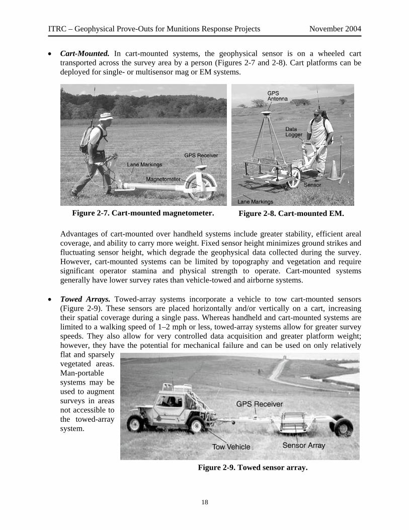
• Cart-Mounted. In cart-mounted systems, the geophysical sensor is on a wheeled cart transported across the survey area by a person (Figures 2-7 and 2-8). Cart platforms can be deployed for single- or multisensor mag or EM systems.
Advantages of cart-mounted over handheld systems include greater stability, efficient areal coverage, and ability to carry more weight. Fixed sensor height minimizes ground strikes and fluctuating sensor height, which degrade the geophysical data collected during the survey. However, cart-mounted systems can be limited by topography and vegetation and require significant operator stamina and physical strength to operate. Cart-mounted systems generally have lower survey rates than vehicle-towed and airborne systems.
• Towed Arrays. Towed-array systems incorporate a vehicle to tow cart-mounted sensors
(Figure 2-9). These sensors are placed horizontally and/or vertically on a cart, increasing their spatial coverage during a single pass. Whereas handheld and cart-mounted systems are limited to a walking speed of 1–2 mph or less, towed-array systems allow for greater survey speeds. They also allow for very controlled data acquisition and greater platform weight; however, they have the potential for mechanical failure and can be used on only relatively flat and sparsely vegetated areas. Man-portable systems may be used to augment surveys in areas not accessible to the towed-array system.
Figure 2-9. Towed sensor array.
Figure 2-7. Cart-mounted magnetometer. Figure 2-8. Cart-mounted EM.
18

ITRC – Geophysical Prove-Outs for Munitions Response Projects November 2004
• Airborne. Airborne survey platforms have been deployed using helicopter and fixed-wing aircraft. Helicopter-based systems (Figure 2-10) have the ability to rapidly collect magnetic or EM data. These surveys require very low flying heights, typically 1–3 meters, to maximize detection capability. The main advantage of these systems is their ability to collect data very rapidly over a large survey area. The main disadvantages are a lower detection capability than ground-based systems (especially for smaller MEC), platform noise, safety issues, and the requirement for the survey area to be relatively flat and free of trees, shrubs, and other obstacles with heights above a meter or so.
Fixed-wing systems (Figure 2-11) can cover large areas very rapidly, but the requirement to fly at a safe ground clearance means that magnetic or EM data collection is impractical. Instead, fixed-wing aircraft typically carry sensors that indirectly detect the presence of subsurface military munitions through their surface expression. Examples include the use of synthetic aperture radar (SAR) to detect surface metal and light detection and ranging (LiDAR) to detect topographic depressions characteristic of bomb craters.
Figure 2-10. Helicopter-based survey.
Figure 2-11. Airborne survey.
Thus, fixed-wing and helicopter airborne sensors are typically used in a wide area assessment role where the task is to identify areas of mass UXO contamination that require additional investigation. Helicopter systems can also be used for individual target detection on large bombing targets.
• Survey Coverage Schemes. Methods and procedures include determining the survey
coverage scheme (Figure 2-12) and defining minimum data collection parameters, such as line spacing and sampling distances. Selection of the survey pattern, instrumentation, and line spacing are dictated largely by the survey DQOs and also by the type and size of munitions believed to be buried.
2.3.3 Positioning Equipment
A positioning technology is needed in digital geophysics to produce any type of representation or mapping of the earth’s surface or subsurface. Positioning technologies determine the sensor’s
19

ITRC – Geophysical Prove-Outs for Munitions Response Projects November 2004
geographic location at each data point recorded. From this information, a map of the sensor response and a record of the travel pathways can be produced. Accuracy, effects of terrain, tree canopy, line of site, ease of use, and costs are generally the most significant criteria for technology selection. Therefore, part of the purpose of a GPO is to test the capability of the positioning technology to be used at the site, including the procedures used to merge the positional data and the geophysical data. Locations can be determined by many different techniques of varying sophistication. Traditional surveying techniques may use tapes and trigonometry to determine relative positions from known ground points. Highly accurate optical laser–based measuring equipment can provide centimeter accuracy in a continuous tracking mode. Other techniques rely upon various applications of differential GPS (DGPS), ultrasonic radio ranging, and inertial navigation systems. In more advanced systems, positioning technologies are directly integrated with geophysical sensors to provide a digital output that can be directly merged with sensor readings for creation of a site map. For DGM surveys, positioning systems locate the
sensor position to enable data interpretation and geophysical anomaly selection for production of a dig list. The ability to correctly locate the position of an emplaced item from the geophysical data depends not only on the positioning technology selected, but also on the physical size of the sensor and the manner in which the geophysical data is processed to determine the location of the anomaly. Various other error sources can degrade anomaly location, including uncorrected motion of the platform in rough terrain, poor data analysis procedures, or timing discrepancies between sensor and navigation system readings. The positioning system used in the survey or a separate system may then be used for the reacquisition of anomalies. It is common practice to employ a second sensor to “pinpoint” anomalies based on locations identified from the initial mapping and the data analysis. This practice may in fact introduce additional positioning errors, depending on the characteristics of the reacquisition sensor and positioning system. The determination of overall system positioning accuracy can be measured by the location picked either during data processing or during reacquisition. Which one is the appropriate measure of overall system location accuracy depends on how the contractor proposes to pick and reacquire targets and should be documented in the work plan.
Figure 2-12. Geophysical survey coverage schemes.
Acceptable positioning accuracy results are based on site conditions, project objectives, and costs. The most desirable positioning systems are ones that are directly integrated with
20

ITRC – Geophysical Prove-Outs for Munitions Response Projects November 2004
geophysical sensors, record data digitally, and map data to provide anomaly locations in all terrain and tree canopies. • Laser-Based Systems. Laser-based survey and tracking systems measure a highly accurate
position relative to a fixed base station location. In a common implementation, a base station is surveyed in at a known location. The base station tripod holds a transmit laser on a robotic mount. The roving sensor platform is outfitted with a prism that reflects the laser from the transmitter. The distance to between the base station and the prism is measured by the time of flight of the laser pulse and the azimuth and elevation angles are accurately tracked by the robotic mount. This information is processed by an on-board computer to calculate the position of the prism in three dimensions. The computer also contains software to lock on to and track the position of the prism in real time to allow on-the-fly data acquisition.
• Differential GPS. GPS satellites orbit the earth transmitting a signal, which can be detected by anyone with a GPS receiver. DGPS increases the accuracy of GPS readings by using two receivers: a stationary receiver that acts as a base station and collects data at a known location and a second roving receiver that makes the position measurements. Base stations can be configured either to transmit the correction data to the rover system or to save the data to be used to correct positional data during post-processing. These corrections increase the accuracy of the GPS readings, with most modern systems capable of locating individual data points with an accuracy of 20–30 cm.
Advantages of positioning using DGPS methods include the accuracy that can be achieved in open terrain, rapid update rate, unlimited range, and ease of operation. System weaknesses include intermittent loss of adequate satellite coverage, which affects the accuracy of the results, and the potential for operators to be unfamiliar with the system’s capabilities and limitations. In addition, tree canopy, deep ravines, or other topographical features can also degrade the system’s accuracy because they can interfere with the GPS receiver’s ability to detect satellite signals.
• Fiducial Positioning. Fiducial positioning is a method of placing electronic markers
indicating locations within a set of recorded geophysical data. To perform the geophysical survey using fiducial positioning, the surveyor depresses the electronic switch to insert a fiducial marker at the beginning of a data set and simultaneously starts walking a straight line at a constant pace. The surveyor continues walking at a constant pace and depresses the electronic switch to place fiducial markers as he crosses the marker ropes. Fiducial markers are typically placed at 25-, 50-, or 100-foot intervals, depending on site-specific needs. It is generally accepted that a well-trained operator can maintain a constant pace and a straight line dead-reckoning (to within 1 foot) between distances of up to 100 feet under good conditions (line-of-site, only minor obstructions, and relatively even ground). Greater distances can be achieved if range markers are used.
The purpose of placing fiducial markers in the geophysical data is to compensate for variances in the speed with which the surveyor walks or drives the geophysical sensor while acquiring data. Fiducial positioning can also be used in the event that the surveyor has to stop due to an obstruction in his path. The process for dealing with obstructions should be defined
21

ITRC – Geophysical Prove-Outs for Munitions Response Projects November 2004
ahead of time in the work plan, demonstrated during the GPO, and documented in a field logbook during the geophysical survey. Key factors governing the success of line and fiducial positioning are the assumptions that a straight line was maintained between fiducial marker points and that a constant pace was maintained during each segment. If either of these assumptions is not maintained, the accuracy of line and fiducial positioned data degrade. It should also be noted that it is very difficult to quantify the accuracy of line and fiducial positioning because, unlike DGPS or any other electronic positioning method, there is no physical or digital record of where the operator actually traveled while collecting the data.
• Ropes-and-Lanes Positioning. Rope and lanes can also be used as a local positioning method. Most commonly associated with “mag and flag” surveys, this method has the advantage of being very “low tech” and can work when other more sophisticated positioning methods break down.
The concept of ropes-and-lanes positioning is to use physical markers on the ground (i.e., the ropes) to create lanes to guide the surveyors (Figure 2-13). Two baselines are established across the opposite ends of the survey area (usually a grid, which is often a 100- × 100- or 200- × 200-foot area). Grid lane lines can then be tied to the baseline knotted rope or stakes. The lane lines mark the boundaries of each 5-foot-wide lane and are used as guides by the magnetometer operators to help ensure complete coverage of the grid. The grid lanes are then surveyed. The survey results are recorded by lane with the relative position of anomalies or other features displayed on a lane or grid map. This method can be accurate within 1 foot if care is taken when recording data on the lane or grid maps and field notes.
Figure 2-13. Ropes-and-lanes navigation in a geophysical survey area.
2.3.4 Data Processing
Data processing encompasses the steps necessary to convert raw survey data into anomaly locations. For mag and flag surveys using analog instruments, the UXO technician interprets the data (i.e., the instrument’s signals) in real time while conducting the survey and immediately identifies and flags anomaly locations. For DGM surveys, digital sensor data is recorded in the field by a data acquisition system (i.e., data logger or computer) and is processed and analyzed after the survey is completed. Digital data processing includes corrections made to the raw data
22

ITRC – Geophysical Prove-Outs for Munitions Response Projects November 2004
to account for sensor drift, heading errors, etc. This sensor data is tabulated and often reported in an ASCII-delimited data file or spreadsheet and includes X and Y coordinate information. Additional information that may be recorded includes values of the measured potential field, time stamp, positioning quality indicators, and instrument operating response. Post-processing of digital data consists of merging the geophysical sensor and positional data, filtering, de-medianing, and gridding. The resulting data set represents the potential fields that were measured. Outputs from data analysis and interpretations usually include maps of the interpreted data and databases of anomaly selections that include coordinate information and anomaly characteristics. 2.4 Geophysical Survey Results and Outcome
In general, the products of the geophysical surveys on an MRS are a map and a geophysical report containing a discussion of site conditions, methods, equipment and procedures, data processing methods, and the QA/QC process for both the survey process and the data management phases of the projects. The report may also include items such as production rates, difficulties encountered in the survey process, and path forward recommendations. The complexity of the report reflects the complexity of the geophysical survey. In addition, the types of maps included in the report vary depending on the type of survey conducted because magnetic and electromagnetic surveys measure different physical properties of the subsurface anomalies. Dig sheets are produced by geophysicists based on analysis of sensor data. Dig sheets may vary in format but always include northing/easting coordinates and anomaly number. In addition, depending on the instrument(s) employed, information about anomaly depth, size, and orientation may also be presented (see dig sheet example in Appendix B). UXO technicians fill in as-recovered information once anomalies are excavated. 3. GPO GOALS AND OBJECTIVES
The fundamental goal of the GPO is to determine whether a particular geophysical investigation approach will work on a given site. Specific objectives of GPOs differ with the unique issues and challenges present at every MRS. Therefore, it is critical that the scope, purpose, and objectives of a GPO be formally developed and documented before starting the GPO’s design. This procedure allows appropriate and specific DQOs to be developed for the GPO. See Chapter 5 for more information on DQOs. The possible objectives of a GPO vary from site to site. The following are some examples of these possible objectives: • Document the consideration given to various geophysical detection instruments for use at an
MRS, the criteria used to identify geophysical instruments for consideration, and the causes for their respective selection or rejection.
• Document the capabilities and limitations of each geophysical detection instrument selected for consideration at the site-specific GPO.
23

ITRC – Geophysical Prove-Outs for Munitions Response Projects November 2004
• Confirm the achievable probability of detection and confidence levels or confidence intervals to support decision making at the site.
• Observe each geophysical detection instrument operating in the contractor’s configuration, using the contractor’s personnel and methodologies.
• Evaluate the contractor’s data collection, data transfer quality, and data QC method(s). • Evaluate the contractor’s method(s) of data analysis and evaluation. • Evaluate estimated field production rates and estimated false positive ratios, as related to
project cost. • Establish anomaly selection criteria. • Document system reliability. The following examples of GPO objectives show how each objective influences GPO design. Example 1: Compare and Evaluate Technologies and Systems One common GPO objective is the comparison and evaluation of multiple geophysical technologies, systems, and/or contractors. A GPO area designed to support this objective is likely to be used by multiple demonstrators using different geophysical systems. The purpose of this GPO objective is to demonstrate or compete various geophysical systems and obtain information to use in selecting an optimum geophysical approach at a site. In this case it is important to identify a location for the GPO that is easily accessible to allow for the efficient implementation of the GPO, while still incorporating the geologic, terrain, and vegetation characteristics of the MRS. It may also be desirable to select representative targets and to bury them beyond the predicted detection depths to allow the demonstrators the opportunity to exceed expectations in this area. Every seeded target becomes an individual test of each system’s capabilities. The individual systems’ results on each target can be directly compared and analyzed to identify each system’s strengths and weaknesses. All geophysical approaches have inherent strengths and weaknesses. Very seldom does one instrument or approach have the best absolute detection rate, the lowest false alarm rate, the highest production rate, and the lowest cost. Therefore, a GPO can provide information used to evaluate each system’s strengths and weaknesses and select an optimum approach for the site. Example 2: Demonstrate Capabilities of a Selected Geophysical System At many sites, a geophysical system is proposed for use without a competitive demonstration. This situation can occur when performance of the system under expected site conditions is not anticipated to be of concern. At many of these sites, specific performance objectives have also been established for the geophysical system. In these instances, the purpose of the GPO is not to select a geophysical system or establish performance objectives, but rather to demonstrate that the selected system can meet the project DQOs for the munitions response action.
24

ITRC – Geophysical Prove-Outs for Munitions Response Projects November 2004
There are several important differences between supporting the objective in Example 1 and supporting this objective that may cause changes to the design of the GPO area and the procedures used. The demonstration GPO performed under Example 1 may use any sensor and operators to demonstrate the system’s relative performance, but demonstrating the capabilities of a selected geophysical system requires testing the entire system—the specific sensor, the specific personnel performing the sensor operation and data processing, and the procedures to be used on the production survey. These individual components of the selected geophysical system are critical to achieving consistent performance from the system, and achieving this objective requires that the system be evaluated as a whole. Other differences from Example 1 include potentially modifying the GPO area to include more targets and modifying the depth of the seeded targets. An analysis of the specific requirements of the production geophysical system may indicate that additional changes need to be made to the GPO area to achieve additional data to support this objective. Example 3: Determine and Document the Performance of a Selected Geophysical System The third type of a GPO arises when a geophysical system has been selected, either by a selection prove-out or by other means. Rather than to compare the performance of the system to a specific performance objective, the goal of this GPO is to establish the performance capability of the system. For example, the geophysical team may want to know the depth to which the selected system can detect a specific target type. It is not uncommon for both a performance determination and a performance demonstration GPO to be conducted within the same site-specific GPO. This situation typically occurs when a contractor is required to demonstrate a specific contractual performance standard and the regulatory agencies require demonstration of the full capability of the system. In such a case, targets buried at depths deeper than the contractual performance depth may be excluded from the calculation of contractual performance objectives, while all are included in determining the system’s performance. 4. GPO TECHNICAL PROCESS INTRODUCTION
This chapter gives a general introduction to each of the major steps in the GPO process for MR actions. It is intended not to describe the technical details of how to accomplish each step, but rather to provide a clear understanding of the overall GPO process and key aspects of each step. The GPO process outlined in this chapter is intended to apply generally to all geophysical survey systems used for MR projects; however, some aspects of GPO design discussed in this guidance may not be applicable to analog, nonrecording instruments. The concepts are still applicable, and a successful GPO can be implemented with little modification. The GPO process can be broken into four distinct phases: design, construction, implementation, and reporting (Figure 4-1). Each phase entails specific activities and deliverables which must be carefully conducted and thoroughly documented. This chapter identifies those activities and defines the general process for conducting a site-specific GPO in support of a munitions response
25

ITRC – Geophysical Prove-Outs for Munitions Response Projects November 2004
action. Detailed information regarding specific regulatory considerations in each phase in the process is presented in Chapter 6. As discussed in the previous chapter, GPOs can have a variety of goals and objectives, which are determined by the site-specific needs and considerations of the site. One or several GPO objectives may be combined—for example, conducting one GPO to both select equipment and validate performance. The determination of the number of GPOs is typically based on the number of competing systems, GPO implementation costs, and technical practicality of performing concurrent levels of evaluation. 4.1 GPO Design
GPO design typically refers to the phase of the GPO from initial scoping to completion of the GPO work plan. The GPO design must be tailored to match the overall approach and objectives of the geophysical survey. The GPO design must also be consistent with the geophysical survey approach planned for the MR action. The design phase incorporates several key components—planning, test plot design, and work plan development. In the actual design of a GPO, planning and design are typically considered in parallel, with the eventual design being documented in the GPO work plan. 4.1.1 GPO Planning
The GPO scope and complexity must be consistent with the goals and objectives of the geophysical survey. To design a GPO that meets project needs, planners must identify and agree on several basic site-specific GPO design parameters during the DQO development process. Information contained in the CSM (military munition type, expected depth, delivery mechanism, etc.) can be used to help determine some of the criteria to be used in designing a GPO. Table 4-1 presents the basic criteria typically necessary for designing a GPO. For example, because detection becomes more difficult as depth below ground surface or the size of the munition decreases, the size of the seed items and the depths of placement are criteria that should be used in designing a GPO. In addition, GPO designers must have a thorough understanding of the physical conditions of the survey site and any possible limitations under which the geophysical survey, and thus the GPO, will be
Figure 4-1. GPO technical process.
26

ITRC – Geophysical Prove-Outs for Munitions Response Projects November 2004
conducted. This minimum baseline knowledge is necessary before beginning the detailed design of the GPO.
Table 4-1. Basic site-specific GPO criteria Importance GPO parameters
influenced Design criteria
Munition(s) of interest
The specific munition(s) of interest should be included in the GPO design to ensure that the detection system used can locate the item(s) at varying, yet realistic, depths and orientations.
• Size, shape, depth, orientation, and composition of seed items
Depth of interest for each munition
Detection becomes more difficult as the depth below ground surface increases or the size of the munition decreases. Therefore, it is important to identify the depth of interest for each munition to ensure that the detection system used can locate each item at the depth needed to meet project objectives.
• Size of seed items • Depth of
placement
Size of smallest munition(s) of interest (i.e., fuzes, bursters, other components)
Smaller items are more difficult to detect than larger items. Therefore, it is important to identify the smallest munition of interest at a depth needed to meet project objectives, as this item will likely dictate the minimum detection level required.
• Size of seed items • Depth of
placement
Composition of munition(s) of interest
If nonferrous items like brass fuzes or aluminum-case flares are anticipated to be found on the site, it is important to understand that magnetic geophysical detection instruments are ineffective at locating these types of items, even though the instruments may detect similarly sized ferrous items at similar depths.
• Composition of seed items
Quantity of munitions
The quantity of munitions to be seeded should be included in the GPO design to ensure that the project objectives are met.
• Number of seed items
Project objectives (characterization, remediation, or removal objectives)
The GPO design should include sufficient number and types of items at critical depths to demonstrate attainment of the GPO objectives.
• Size of seed items • Depth of
placement • Number of seed
items Acceptable geophysical survey confidence and uncertainty levels
The minimum number of seed items required is a function of the probability of detection and confidence level.
• Number of seed items
• Size of seed items • Depth of
placement Survey coverage and geometry
The GPO should be designed to evaluate the specific type of survey coverage being considered (full coverage, transects, meandering path, etc.). The GPO should also evaluate the same sensor geometry as the system that will be deployed during the actual site survey.
• Test grid size and geometry
• Target placement geometry
The scope and complexity of the GPO are typically dictated by the goals and objectives of the MR action and geophysical survey. Depending on the project needs, a GPO can range from simple to complex, and on large, complex sites, more than one GPO may be required. The scope of the GPO can also be influenced by the degree of confidence in the survey system’s ability to meet project objectives. How difficult is it anticipated to be for the geophysical system to find the munitions of interest? Has the geophysical system been successful at similar projects under similar site conditions? For the occasional site types, it may be appropriate to limit scope and complexity of the GPO. Conversely, an extensive prove-out may be dictated by projects where there are complex or varying site conditions or difficult-to-detect munitions or where a detailed comparison of geophysical systems is required or desired. For these very complex projects,
27

ITRC – Geophysical Prove-Outs for Munitions Response Projects November 2004
hundreds of inert munitions may be buried in a relatively large area at many depths and orientations to closely match the expected population of munitions in the field. The GPO scope may also be limited by the scope of the geophysical survey project. For example, if the goal of the survey is limited to identification of areas of potential munitions contamination, the scope of the GPO may be limited to mapping, positioning, and data processing elements. However, if the goal of the MR action is subsurface clearance, the GPO should include evaluation of the reacquisition of the anomalies. 4.1.2 GPO Test Plot Design
Designing a GPO test plot design includes selecting the GPO test site, determining the seed targets, and specifying the GPO search pattern and mapping procedures. This section discusses each of these aspects and how it influences the GPO design. GPO Site Selection—Several basic parameters must be considered in the selection or evaluation of a suitable GPO location. These location-specific considerations are important to ensure that GPO results will be representative of the conditions expected across the entire survey site and that the GPO, as well as the production survey, can be implemented safely and efficiently. Basic parameters that should be taken into consideration in GPO site selection include the following: • Terrain and vegetation at the
potential GPO site should be similar to those across the survey area.
• The geophysical noise conditions existing at the GPO site should be similar to those expected across the survey area, including the soil type (e.g., moist silty soils, dry sandy soils, moist clayey soils), electrical conductivity, magnetic susceptibility, etc.
Major GPO Design Components
I. GPO Planning • Determine goals and objectives • Determine scope and complexity • Determine DQOs
II. GPO Test Plot Design
• Site selection • Seed items • Search pattern
III. GPO Work Plan
• Document design s • Establish procedure
• Define work tasks
Tailoring the GPO Area to the Specific Site Requirements
The GPO for the Adak, Alaska munitions response project presented several challenges to the Navy and its contractor. Significant variations in terrain (steep, moderate, and flat slopes) and vegetation (none/rock, short, medium and tall tundra and hummocks) across the MRS had to be duplicated at the selected GPO site. Upon analyzing the requirements, the project team determined that 100% survey coverage wasn’t required and that the GPO could consist of transect surveys because that method would duplicate the transect surveys planned for characterization of the site. The Navy’s contractor located a potential GPO site that had the following attributes: • one long (750-m) meandering transect, • starting and ending at the same location, near a
road, and • covering all of the terrain and vegetation types
selected for inclusion in the GPO. The selected geophysical sensor and process were demonstrated to meet the GPO objectives and DQOs for the identified terrain and vegetation combinations. This resulted in significant project cost savings because one conveniently located GPO was constructed instead of multiple smaller GPOs at various locations, resulting in decreased GPO construction and maintenance costs.
28

ITRC – Geophysical Prove-Outs for Munitions Response Projects November 2004
• The GPO site should be large enough to accommodate all necessary GPO tests and equipment and for adequate spacing of the seed items to avoid ambiguities in scoring and data analysis.
• The GPO site should be readily accessible to project personnel but restricted for nonproduction personnel.
• The GPO location should be on or in close proximity to the actual survey site. A perfect GPO site may not exist; therefore, it is often necessary to balance the above criteria in the selecting the best site. At some sites, a portion of the actual survey area may be the best location for the GPO, or multiple locations may be needed to test varying, diverse site conditions. GPO Test Areas—GPO test sites typically have two main test areas: a function check area and a test plot, although not every GPO requires a function check area. The function check area is used to ensure that equipment, operators, software, and models work under the general site conditions (soil and munitions types, etc.). Function check area surveys are typically conducted by or under the direct supervision of the senior project geophysicists. The demonstrators are provided detailed information on the types and locations of seeded items in this area. Additionally, the terrain and other site conditions are typically more conducive for geophysical data collection than may be experienced across the MRS. The function check area enables demonstrators to test their geophysical system, build a site library, document signal strength, and deal with site-specific variables in a controlled manner. The test plot (also referred to as the “field test area”) is used to demonstrate that the geophysical detection system works under not only optimal but also typical field conditions. The field test area survey should be conducted by personnel with the same level of expertise and experience as the personnel who are to conduct the geophysical survey of the MRS. Demonstrators test their technology and methodology (equipment, operators, processing, and analysis) against unknown seed items under typical field conditions, which can include uneven terrain, varied vegetation, fences, power lines, clutter, and other site-specific challenges. The locations of seeded items in the test area are not disclosed to the demonstrators (both the field personnel and the data processors) until the data is fully processed and targets are selected. GPO Seed Item Selection and Placement—The selection of seed items for a GPO includes determining the types of seed items, the quantity of each type of item, the placement of each item (location, depth, and orientation), and the amount and type of clutter, if any, to use. The decisions should reflect the anticipated conditions of the production area. Many of the decisions related to seed item selection and placement are driven by the basic design criteria and DQOs (see Chapter 5 for more information on how these decisions relate to the DQOs). • Type—Seed items used in the GPO should reflect the types of munitions expected to be
present on the MRS and should include the most difficult to detect (often the smallest) items of concern.
29

ITRC – Geophysical Prove-Outs for Munitions Response Projects November 2004
• Quantity and Placement—A sufficient number of seeded items should be used to meet project objectives. The quantity and placement should be sufficient to evaluate detection system performance with respect to a variety of variables, including the following: - the munitions of interest; - the orientation of the munitions (i.e., items should be placed at several different
orientations); - depth of detection (i.e., items should be placed at different depths); - enough encounters to capture random factors such as relative orientation, exact line
placement, etc.; and - site-specific performance metrics as identified in the DQOs.
The DQOs may include common contractual performance metrics such as the probability of detection (Pd) at a specified confidence level (CL). Care should be taken to devise an emplacement plan so that Pd and CL can be determined on the specific population of interest (i.e., the population of all munitions and all expected depths vs. specific munitions and specified depths). There may be a practical limit to the number of items that can be accommodated in the GPO, which limits the extent to which items of interest can be subdivided and therefore the ability to demonstrate the actual Pd and CL for the intended population (see also Section 5.2.2.).
• Clutter—The amount and type of clutter
seeded in the GPO area should be representative of what is expected in the production site to maximize discrimination effectiveness. Clutter can be added to the GPO area to address two separate issues: detection and discrimination. Clutter can include range scrap metal, salvaged scrap metal, old weapon clips, cartridge cases, etc. Munitions-related clutter items (i.e., fuzes, booster charges, propellant, explosive filler, etc.) must be inspected and certified by a UXO supervisor as free of any explosive materials.
GPO Test Plot Search Patterns—The GPO test plot search pattern must be consistent with the search pattern and/or coverage scheme previously determined for the overall geophysical survey of the MRS (Figure 2-12). GPO search pattern parameters vary depending on the search pattern, coverage scheme, and DQOs. Different GPO test plot coverage schemes can have significantly different results with the same survey equipment. For example, a full coverage magnetometer survey scheme can provide multiple “looks” (i.e., adjacent passes of the sensor over or near the seed item), while a transect survey may only have one “look” at the seed item. Depending on the size, depth, and orientation of the item, having multiple “looks” may increase the chances of detecting the item. Thus, if a transect coverage scheme will be used for the production survey, it is important that the same coverage scheme be evaluated as part of the GPO. It is also important to recognize the limitations of a GPO in the design of a transect survey. The GPO can be used to determine the performance capability of the survey method at the transect
Clutter Clutter items may include fragments of military munitions (also called “munitions debris”) or non-munitions-related, manmade metallic objects (also called “cultural debris”) or magnetic rock.
30

ITRC – Geophysical Prove-Outs for Munitions Response Projects November 2004
level. However, the GPO cannot be used to evaluate which transect survey design would best characterize a site. For example, a GPO cannot be used to determine the relative merits of different transect line spacings to characterize a MRS. 4.1.3 GPO Work Plan Development
The GPO work plan documents the GPO goals and objectives, specific DQOs, and GPO design elements. The GPO work plan can be developed as a stand-alone document or as part of the geophysical investigation or removal work plan. The size and complexity of the GPO and geophysical survey, along with regulatory and stakeholder considerations, dictate the need for a separate GPO work plan. Whether stand-alone or integrated into another work plan, a GPO work plan describes how the GPO will be accomplished by defining work tasks and establishing methods and procedures. The GPO work plan should, at a minimum, address basic elements (Table 4-2) and should be reviewed and approved prior to site construction or GPO implementation.
Table 4-2. GPO work plan elements GPO element Work plan content
Test area layout Include the proposed test area layout, showing the prove-out type, size, location, and search pattern and a list and map of all seed items and their placement.
Site preparation Describe any preparations that may be necessary to allow accessibility with geophysical instruments. These may include vegetation removal and/or surface removal of MEC.
Survey specifications Describe the method to be employed to locate test plot corners, seed item burial locations, equipment, monuments, coordinate systems, and angle definitions. On many projects the use of a professional land surveyor is required.
Baseline geophysical survey
Describe background (preseed) geophysical mapping to be performed to document baseline geophysical conditions at the site.
Quality control Describe the quality control measures to be implemented for the GPO. Anomaly avoidance Describe the procedures to be used at the site to ensure that the location of each excavation
and corner marker is clear of metallic anomalies before placing seed items. Seeding Describe the planned seeding methodology for the site, including known items, blind items,
item placement (including approximate depth and orientation), and excavation procedures. Data collection procedures and variables
Describe the field procedures to be followed during data collection and data elements for each detector type utilized in the GPO. Examples of some of these elements include instrument height, instrument orientation and direction of travel, instrument channel selections, measurement intervals along survey line, lane width, etc. Some data elements are subject to modification and evaluation in the field, which should be noted in the report, along with any limitations related to field implementation.
Data analysis and interpretation
Describe the methodology to be employed for the analysis and interpretation of the geophysical survey data, including all anticipated field and post-processing steps and example dig sheets.
Reacquisition (DGM surveys only)
Describe the procedures for anomaly reacquisition and verification.
Data evaluation Describe the methodology, performance metrics, and scoring criteria to be used to evaluate results of the GPO. For a GPO to select equipment, these should include how the different systems and/or survey approaches will be evaluated.
31

ITRC – Geophysical Prove-Outs for Munitions Response Projects November 2004
4.2 GPO Construction
The GPO construction phase consists of three major tasks—site preparation, seed item emplacement, and site construction documentation. Each task in site construction should be clearly identified and described in the GPO work plan. It is critical to the success of the GPO that these tasks are fully implemented in accordance with the GPO work plan. Any field variations must be fully documented and reported to the geophysical team. As possible, state regulators should perform field oversight to ensure that the construction is consistent with the sampling design as documented in the work plan. 4.2.1 GPO Site Preparation
The first step in GPO site construction is site preparation. GPO site preparation encompasses any tasks necessary to prepare the GPO site before seed item emplacement. Site preparation can include a site boundary survey, surface removal, vegetation clearance, and/or baseline survey. However, not all site preparation tasks are needed at all sites. Establish Site Boundary—The extent of the survey needed to establish a GPO site depends on the scope and complexity of the GPO and the level of existing data available for the site. At a minimum, the GPO site boundary should be marked and surveyed and a land survey marker or benchmark located. A first-order survey marker is preferred. The survey marker should have both horizontal and vertical controls. Depending on the positioning system being deployed, a survey marker may also need to be placed within line of sight of the test areas. If not already available, a topographical land survey is also conducted across the site and includes tree lines, telephone lines, utilities, or other features. The topography is useful in obtaining geophysical background characteristics of the entire test site. The datum and coordinate system used during the survey should be documented and used consistently throughout the entire GPO process. Surface Removal—If there is a potential for munitions hazards on the GPO test site, the surface and subsurface of the entire area that makes up the proposed GPO site must be cleared of any munitions hazards. Furthermore, anomaly avoidance measures must be followed when selecting seed item burial locations. The GPO work plan must specify how inert munitions items, scrap, fragments, and other surface clutter items will be addressed during surface removal. In most instances, all surface items are removed from the site during the surface sweep. Any clutter needed for the prove-out can then be placed back into the test plot during seed item emplacement. Vegetation Clearance—The conditions of the GPO site should mimic those found in the production area. Vegetation removal should be conducted to duplicate the production area conditions. Baseline Survey—The baseline geophysical survey of the GPO site is conducted before seed item emplacement to determine the presence or absence of existing anomalies and to establish background geophysical responses. Existing anomalies can be removed or documented. In
32

ITRC – Geophysical Prove-Outs for Munitions Response Projects November 2004
addition, any soil sampling, soil property measurements, and/or soil moisture levels determined by the geophysical team to be necessary for the prove-out can also be conducted at this time. 4.2.2 GPO Seed Item Emplacement
Acquisition and Selection—Two types of seed items can be used on a GPO site—munitions and clutter. Potential sources of these seed items include items recovered during previous response actions at the site or at other sites or surrogate items. The lead time for acquiring seed items should be factored into the site activities for realistic planning. Because surrogates introduce additional uncertainty into the testing process, inert items recovered from the site are the preferred seed items for the GPO. If munitions are unavailable, surrogates of approximately equal size, shape, and material composition should be used. When using surrogates, care must be taken to ensure that the surrogate items’ geophysical signatures will be representative of the signatures of items of interest expected to be encountered at the site. Clutter Considerations—Clutter items emplaced on the test site are considered seed items and should be treated as such. Therefore, the use of clutter on the test site should be representative of the clutter expected to be found on the production survey site. Emplacement—Seed items are emplaced according to the GPO design. Items should be buried at the depths, attitudes, and orientations that are expected in the MRS. Emplacement is typically conducted by digging a hole to the appropriate depth, placing the item in the hole at the prescribed depth and orientation, surveying its location, photographing the item, and backfilling the hole (Figure 4-2). A backhoe, auger, or posthole digger may be used to place items. Efforts should be made to minimize the size of the disturbance while placing seed items and to ensure that the confidentiality of the site is maintained. Seed placement location can be masked by grading and revegetating seed locations. These locations can also be allowed to weather so that surface scars are not evident. To ensure that items are not being selected due to ground disturbance, several holes should also be dug and filled in without placing items and their locations documented.
Figure 4-2. GPO seed item emplacement.
33

ITRC – Geophysical Prove-Outs for Munitions Response Projects November 2004
4.2.3 Site Construction Documentation
As with all phases of the GPO, it is critical that the construction of the GPO test site be clearly and thoroughly documented. Depending on the complexity of the project and GPO, the documentation can vary from a letter report to a full site construction report and as-built drawings. During the design phase, the geophysical team should determine the required level of documentation of the GPO construction. At a minimum, the GPO construction report should contain a map of the test plot location; a diagrams showing seed item locations; a spreadsheet showing emplaced locations, depths, orientations, depths, etc.; photographs of all seed items; survey data; names of the people that constructed the test plot; and the date of construction. 4.3 GPO Implementation
After the GPO is designed and constructed, geophysical systems are tested in accordance with the work plan. Because the ultimate goal of the GPO is to confirm that selected geophysical survey equipment and methods are appropriate for the site, it is important that the GPO survey be conducted in the same manner as the production survey. Therefore, GPOs should be implemented using key geophysical personnel, equipment types and configurations, survey procedures, data analysis, and anomaly identification and reacquisition methods in the same manner as will be used during the production survey. This helps maintain the integrity of the GPO and adds validity to the GPO process and the data collected. The skill levels of personnel executing the prove-out, both field personnel and geophysicists, should be specified in the GPO design and should closely match the level of personnel that will execute the production survey. Otherwise the GPO results may not be representative of the system performance to be expected during the production survey The GPO should also imitate the production survey’s design elements such as survey speeds, coverage, and data density. Furthermore, the time taken to collect and process the data should be monitored to ensure that excessive time is not spent collecting an idealized GPO data set that would not be representative of actual survey performance. At some sites, the GPO test plot is also used for geophysical survey system certification (sometimes referred to as “system validation”). In such cases, the GPO is repeated by each field team with the specific equipment that will be used to conduct the actual production survey. Geophysical mapping system certification is a QC tool that can be implemented during the site survey using the GPO test plot. The need for and value of this tool are currently under debate. The need for geophysical system certification should be determined by the geophysical team during the scoping of the response project and may influence the design of the GPO test plot. 4.3.1 GPO Field Mapping and Data Collection
The GPO report should fully document the equipment used, survey speed, survey coverage, and data acquisition rates. In addition, the function checks and setup procedures for all acquisition and sensor equipment should be documented, and any deviances should be noted. For mag and
34

ITRC – Geophysical Prove-Outs for Munitions Response Projects November 2004
flag surveys, the procedures, equipment settings, and search patterns used should be noted for exact duplication during the production survey. A daily logbook is typically used to record all on-site activities and field notes and should include such information as the reliability of equipment, number of people, start/end time for data collection, maintenance time, function checks, etc. 4.3.2 GPO Data Documentation and Management
GPO data should be collected and managed using the procedures that will be used during the actual production surveys and that have been documented in the work plan. If possible, state regulators should observe the data collection in the field to verify that the methods and procedures are consistent with the sampling design as documented in the work plan. 4.3.3 GPO Data Analysis
In a mag and flag survey, data analysis consists of the UXO technician making an interpretation of audio and visual signals in real time. Maps are then produced that show the locations of the picked targets (see Appendix C for examples). In a DGM survey, a geophysicist processes the raw data collected during the survey and then analyzes and interprets the results to select targets. Data analysis and interpretation are generally the result of a multistep process and typically include computer processing, including leveling of the electromagnetic signals recorded by the geophysical sensor. The processed data is analyzed to establish a threshold or minimum signal strength of signal responses, which is based on the geophysical signatures of the military munitions of interest, and may also depend on the background geologic noise level of the site. Signal responses above the established threshold are selected and reviewed by the project geophysicist to minimize false positive responses. The geophysicist also reviews the signals below the established threshold to ensure that there were no false negative responses. All of the targets identified during this analysis are recorded on a dig sheet. Dig sheets (whether produced by either a mag and flag or DGM survey) include all information available on the instrument response to the target. Dig sheets may vary in format but always include northing/easting coordinates and anomaly number. In addition, depending on the instrument(s) employed, information about anomaly depth, size, and orientation may also be presented. The U.S. Army Corps of Engineers (USACE) uses a standardized dig sheet on all MRSs. During the GPO process, only the first seven columns are typically completed. The remaining columns are completed throughout the investigation and remediation phases of the project. 4.3.4 Target Reacquisition
For DGM surveys, the final GPO field activity is target reacquisition. Target reacquisition tests and demonstrates the ability to accurately record the location of the selected anomaly, navigate back to the selected anomaly, and then determine the precise anomaly location using a geophysical sensor. To do this, a technician searches within a predetermined radius around the
35

ITRC – Geophysical Prove-Outs for Munitions Response Projects November 2004
identified anomaly location. Once the anomaly is reacquired, the technician marks the exact location of the anomaly with a pin or flag and determines the precise X and Y coordinates of the anomaly. This marked location will be used to score the ability to reacquire the anomaly, the interpretative location, the reacquisition location, and the results of the GPO. Again, in the case of a GPO intended to certify a geophysical system, the exact personnel, equipment, and procedures should be the same as those to be used for the production survey. 4.3.5 Evaluation of GPO Results
Each seeded target should be scored as a “pass” or “fail” based on whether the seeded target was successfully detected and relocated within the maximum allowable radius as described by the DQO for positioning accuracy. Because site-specific conditions and the types of munitions of interest affect different geophysical systems differently, evaluating the results of a GPO comparing multiple candidate systems can be difficult. Very seldom does one system or approach have the highest Pd, lowest false alarm rate (FAR), greatest efficiency, lowest cost, and least environmental impact. Therefore, the geophysical team members must use the GPO information in a trade-off analysis to select the optimal geophysical approach for the project, and the trade-offs should be communicated to everyone involved in the project before a final decision is made. 4.4 GPO Reporting
The final product of the geophysical prove-out is the GPO report. This report documents the performance of the system(s) used in the GPO and the ability to meet the project objectives. This section discusses the key aspects of the GPO report, including report content, GPO findings and conclusions, and QA/QC. A draft GPO report should be distributed for review before finalizing. The final GPO report should be included in the administrative record established for the munitions response project. 4.4.1 GPO Report Content
The content and complexity of the report is tailored to reflect the complexity of the GPO. The exact contents of the report are dictated by the DQOs established at the onset of the project. Therefore, a report that details the application of sophisticated digital geophysical EM survey equipment will differ from a report on a mag and flag survey. Outline for Reporting, Required Elements—In general, a GPO report discusses site conditions, methods, procedures and instrumentation employed, data processing methods, and the QA/QC process for both the survey process and data management. The following elements should be included in all GPO reports:
Example GPO Report Table of Contents
1. Introduction 2. GPO Objectives 3. Test Grid Locations and Design 4. Equipment 5. Procedures 6. Data Processing and Management 7. Results 8. Quality Control 9. Conclusion Appendix A. GPO Seed Item Pictures Appendix B. Raw and Processed Data Appendix C. Dig Sheets
36

ITRC – Geophysical Prove-Outs for Munitions Response Projects November 2004
• as-built drawing of the GPO plot; • pictures of the seed items; • color maps of the geophysical data (DGM surveys only); • summary of the GPO results; • proposed geophysical equipment, techniques, and methodologies to be used for the
production survey; and • sufficient supporting information to justify recommendations. The GPO report may also include items such as production rates, any difficulties encountered in the survey process, and path forward recommendations. Maps and Photos—The report should include photographs and descriptions of all instruments and equipment used in the survey. The GPO results section should include GPO survey maps, anomaly maps, dig sheets, and reacquisition results similar to those of a production survey. These results should also be compared to the seed item data and discussed in terms of system performance and the ability to meet the DQOs. Electronic Data Reporting—In addition to the written report, the GPO report should include electronic submittals of all GPO data files. This data should include copies of the raw data files, processed data files, processing logs, and any other intermediate data sets critical to the data processing and analysis. Data sets should be submitted in industry standard formats and include sufficient descriptions to allow for independent auditing and reprocessing. 4.4.2 QA/QC Reporting
The QA/QC procedures used throughout the GPO process should be documented and include discussions of the following: • equipment function checks, • personnel qualifications, • data collection operations procedures, • target parameters, • positioning system operations/limitations/accuracy, and • data management/processing. QA programs can consist of whatever quality inspections are determined to be appropriate by the accepting agency. These inspections can include observation of field personnel during the performance of their duties to ensure that they are working in compliance with the approved work plan, independent confirmatory sampling, and reporting and documentation of QA results. QC procedures are conducted throughout any investigation process and typically include morning and evening standard response tests, a static test prior to beginning data collection of each grid, and collected repeat data over each grid.
37

ITRC – Geophysical Prove-Outs for Munitions Response Projects November 2004
4.4.3 Reporting Conclusions
The specific finding and conclusions depend on the type of GPO conducted but should address detection capability, along with positioning system capabilities and data quality. Every GPO report should answer the following questions: Did this GPO meet its goals and objectives? Is the selected geophysical survey system appropriate for this site? Will the selected system meet the objectives of the MR action? 5. DATA QUALITY OBJECTIVES AND PERFORMANCE METRICS
In keeping with the philosophy and the systematic planning process recommended by the Interstate Technology & Regulatory Council, GPOs should be planned and executed to determine the type, quantity, and quality of data sufficient for environmental decision making. Both USACE and the U.S. Environmental Protection Agency (EPA) have systematic project planning approaches that are relevant for the planning of munitions response geophysical surveys and GPOs (USACE 1998, EPA 2000). The DQO process established by EPA and discussed below is one example of how the systematic project planning approach has been applied to MR actions. Performance metrics can be used to score the data results of a GPO to determine whether seeded anomalies were successfully detected, identified, and reacquired. Determination of applicable DQOs and performance metrics is site specific and may vary from GPO to GPO. 5.1 Data Quality Objectives
DQOs are quantitative and qualitative statements that specify the type and quality of the data needed to support an investigative activity. They are developed before data are collected as part of sampling program design. EPA has developed a seven-step sequential and reiterative process for developing DQOs as follows: 1. State the problem. 2. Identify the decision. 3. Identify the inputs to the decision. 4. Define the study boundaries. 5. Develop a decision rule. 6. Specify acceptable limits on decision errors. 7. Achieve optimal design for field sampling design. This seven-step process is aimed at achieving an “optimal design” for obtaining the desired data necessary for geophysical surveys and prove-outs. The outputs from each step of the process result in the DQOs. These DQOs are statements that • clarify the objective of the data collection effort, • specify how the data will be used to support the risk management decision being addressed, • define the most appropriate type of data to collect,
38

ITRC – Geophysical Prove-Outs for Munitions Response Projects November 2004
• specify acceptable levels of decision errors that will be used as the basis for establishing the quantity and quality of data needed,6 and
• specify the quantity and quality of data to be collected. By using the DQO process, the geophysical team members can clearly define what data and information are needed and develop a data collection design to help them obtain the type, quantity, and quality of data needed to make a sound decision about whether a technology has been effective. Once DQOs are established for the GPO and before the GPO is implemented, the DQOs should be documented in the work plan. DQOs are an integral part of QA/QC that are used to specify the acceptable limits for decisions that will be used as the basis for establishing the quality and quantity of data needed to support decisions. Supporting DQOs establish the quality acceptance criteria such as precision, sensitivity, accuracy, and completeness (Table 5.1). The GPO report should document the meeting of DQOs and any variances. In the event of variances, the QA process and QC checks also should ensure that the variances were documented and that the effect or lack of effect on data usability is understood and accounted for relative to subsequent site decisions. The reported results should be reviewed by the geophysical team prior to the commencement of the production survey to ensure that all technical and project managers are in agreement that the established DQOs are being met. 5.2 Performance Metrics
Performance metrics are the definable and measurable aspects of the various types of data as required by the DQOs. Another way to look at performance metrics is to think of them as the measurable criteria from the GPO data that are scored to determine whether seeded anomalies were successfully detected, identified, and relocated. Like DQOs, determination of appropriate performance metrics is site specific and therefore varies from GPO to GPO. 5.2.1 Probability of Detection
Pd is a statistically meaningful parameter that describes the probability of detecting an item of interest. Although Pd and “percent detected” are often used interchangeably, percent detected is the one-sample measure of the number of MEC items detected divided by the number emplaced. Unlike percent detected, a true probability is calculated on a statistically significant population of items that all have the same chance of being detected and captures the random processes that effect detectability. In other words, true Pd is calculated on a population of items made up of single munition type at a single depth and orientation to capture the effects of the exact location of sample points relative to the item, the positioning uncertainty, etc. However, it is not practical to perform such an exercise on a GPO. As a substitute, an array of munitions of interest is emplaced at a range of depths and orientations, and the Pd is calculated on a single sample of the array of munitions. Therefore, the Pd does not necessarily represent the probability of detecting items in the population as they occur in the field.
6 A decision error rate is the probability of making an incorrect decision based on data that inaccurately estimate the true conditions at the site.
39

ITRC – Geophysical Prove-Outs for Munitions Response Projects November 2004
Table 5-1. Sample GPO DQOs7
Data quality indicator Example measurement performance criteria Data type
Geophysical survey and anomaly identification Precision • Response to standardized item will not vary more than ±10% Representativeness • Survey to achieve 0.85 Pd at 90% CL for all 60-mm mortars within 2
feet bgs • Sensor to identify at least 90% of all munitions seed items or their
surrogates Sensitivity • Sensor to identify 60-mm mortars at a minimum of 2 feet bgs
Geophysical sensor data
• Sensor to identify 20-mm projectiles to a depth of 12 inches bgs • Standard deviation of background noise = <3 mV • Signal-to-noise variance = < lesser of 5% or 5 mV
Accuracy • Percent false positives not to exceed 15% of all identified anomalies Completeness • At least 98% of possible sensor readings will be captured along a
transect Precision • Positional error at known points will not exceed ±20 cm Accuracy • Interpreted locations of anomalies within 0.5-m radius of actual location
Positional data
Completeness • Search transect spacing to vary no more than ±10% of spacing specified in sampling design
• Along track sampling of <0.5 feet • Across track sampling of <0.3 feet, excluding data gaps due to trees or
other obstacles • Total acreage of data gaps not to exceed 0.25 acres
Anomaly reacquisition Precision • Response to standard object will not vary more than ±10% Representativeness • Survey to achieve 0.85 Pd at 90% CL for all 60-mm mortars within 2
feet bgs Sensitivity • Sensor to identify 60-mm mortars at a minimum of 2 feet bgs
Geophysical sensor data
Accuracy • Percent false positives not to exceed 15% of all identified anomalies Precision • Positional error at known monuments will not exceed ±20 cm Positional
data Accuracy • Reacquired locations of anomalies within 0.5-m radius of actual location• Anomaly reacquisition within 2 feet of interpreted locations
Anomaly excavation Precision • Response to standard object will not vary more than ±10% Geophysical
sensor data Accuracy • All excavations cleared of metallic items Precision • Positional error at known monuments will not exceed ±20 cm Accuracy • Type, condition, and fuzing state (no fuze, unarmed fuze, armed fuze) of
munitions items correctly identified
Positional data
Completeness • Anomaly identification forms completely and correctly filled out for each anomaly
5.2.2 Confidence Level
The CL is the probability value that the Pd measured on the GPO is representative within the required limits of the true Pd of the system on the test plot. A common contractual requirement is for a Pd of 0.85 at a 95% confidence level. The number of targets determines the lower bound on
7 The DQOs shown in this table are examples of DQOs that have been used on MRSs. However, these DQOs are not applicable to all sites. DQOs should be developed for each GPO, based on site specific characteristics, project objectives and methodologies used.
40

ITRC – Geophysical Prove-Outs for Munitions Response Projects November 2004
the true Pd at a specified confidence level, with a lower number of targets resulting in a lower confidence level. For example, if the GPO site is seeded with 10 emplaced targets and a demonstrator successfully detects 9 targets, the resulting Pd estimate is 90%. If the same GPO is seeded with 100 emplaced targets and the demonstrator successfully detects 90, the Pd estimate is also 90%. However, in the first scenario, with a smaller number of seeded items, the lower confidence limit at 95% confidence level is 0.55, where in the second example with the larger number of seed items it is 0.82. Therefore, the sample size (i.e., the number of emplaced items) must be large enough to ensure the required statistical significance. The CL is calculated using statistics that are beyond the scope of this document. Because the populations may differ in depth distribution and relative abundance of different munitions types from the survey area, the Pd and CL from the prove-out are not necessarily accurate estimates of those parameters that can be expected to be achieved in the field survey. 5.2.3 False Negative
A false negative is the omission of MEC from the dig sheet. This may result from either the failure of the geophysical instrument to detect a response to the target or the response being misidentified during data processing. These errors result in risks remaining following the completion of the MR action. 5.2.4 False Alarm/False Positive
A false alarm, also referred to as a “false positive,” occurs when an identified anomaly is incorrectly selected as a possible target when no object is present. This term may also be applied to a declared target location that does not correspond with the actual target location. False alarms typically result in unnecessary excavations, which ultimately inflate project costs. False positives can be the result of sensor noise, motion noise, data collection or processing artifacts, personnel error, or a difference in capabilities of the search and reacquisition sensors. 5.2.5 False Alarm Rate
The FAR is a measure of the number of incorrect target anomalies selected and occurs when geophysical data acquisition or data processing indicates a response that is not associated with a target item. False alarms can occur associated with anomaly detection vs. false alarms associated with anomaly discrimination. An anomaly that exists in the data but turns out to be associated with instrument noise is a false alarm in the context of anomaly detection. However, an anomaly that is selected but turns out to be associated with an iron-bearing rock or a buried utility is not a false alarm in the context of anomaly detection. By contrast, an anomaly that has been passed through an anomaly discrimination process and is declared an item of interest but turns out to be associated with an iron-bearing rock or a buried utility is considered a false alarm in the context of anomaly discrimination. For example, one possible cause of a false alarm associated with detection can occur when an active electromagnetic sensor coil bumps into the ground during data acquisition. If this accidental bump produces a spike in data intensity, the data could be interpreted as representing a subsurface anomaly. It is often difficult to determine the cause of a false alarm unless a good background geophysical survey was performed on the GPO site prior
41

ITRC – Geophysical Prove-Outs for Munitions Response Projects November 2004
to emplacement of seed items. It is also important to note that as sensor sensitivity increases, sensors detect more targets of interest, which may increase the number of false alarms as well. Some federal contracts specify or define a maximum number of false alarms as a percentage of the number of target picks that can be associated with an actual subsurface metal object. However, there is no absolute rule to determine an acceptable FAR. From a regulator’s perspective, a high FAR may increase the possibility that the target items are going to be detected. However, the inefficiencies associated with a high FAR increase field efforts, data processing and handling, and the likelihood of errors and may decrease the overall quality of the GPO and project fieldwork results. 5.2.6 Signal-to-Noise Ratio
When GPOs are used to determine the operating envelope of a system or to confirm the correct functioning of equipment, the appropriate metrics relate to signal strength and the noise environment in which signals must be detected. The signal strength and system noise are often combined in a signal-to-noise ratio (SNR). The target’s signal strength is reported in the operating units of the instrument, i.e., nanoTesla (nT) for a magnetometer and millivolts (mV) for an EM instrument. The appropriate number may be the maximum amplitude of a target signal or the signal integrated over its spatial extent, depending on how the targets are selected. In either case, the signal strength for a selected target at a specified distance and orientation is measured. In the selection of equipment, this value may be compared to the associated noise measurements to establish the operating envelope of the system. The repeatability of this value may be used to determine whether equipment is functioning correctly and being used properly. Noise is measured in the same operating units as the sensor. Noise is commonly divided into sensor noise and environmental noise. Sensor noise is the fluctuation in sensor output in the absence of an external signal and is generally dominated by noise in the sensor electronics. Depending on the application, the sensor noise may be reported using a peak-to-peak fluctuation, a root mean square measurement, or some other statistical measure. The sensor noise characteristics should remain stable with time, so this quantity is relevant to determining whether a sensor is operating properly. Environmental noise captures other external sources that also compete with the signal of interest. These sources can include electromagnetic interference, geological noise, or other types of clutter. In the case of MEC detection, environmental noise is generally the dominant contributor to the overall noise of the system. The amount of noise is relevant to determining the signal strength that will be required to reliably detect items of interest in the real-world environment of the site. Consequently, the signal strength of the target must exceed the sum of the sensor noise and the environmental noise. The SNR is the ratio of these two metrics (target strength to noise) and is a dimensionless quantity. In general, SNRs of a minimum of 2–3 are required for reliable detection. Higher values are required to discriminate anomalies from noise and facilitate analysis. It is fairly common to make estimates of target size and depth from magnetometer data, which can be very accurate with good SNR and positioning information.
42

ITRC – Geophysical Prove-Outs for Munitions Response Projects November 2004
5.2.7 Positional Accuracy
Positional accuracy is measured by comparing the known location of the emplaced targets to the reported location of the anomalies detected, selected, and reacquired by the GPO demonstrator. The geophysical team must determine the requirement for positional accuracy error based on the expected field requirements and specify this accuracy requirement to the GPO demonstrators. During the reacquisition phase of the field survey, the positioning accuracy requirement is used to determine the size of the radius around an established geophysical anomaly location. Field personnel must search in this radius with another geophysical sensor to reacquire the anomaly and determine its exact location. 5.2.8 Object Depth vs. Diameter
In general, larger objects may be detected at greater depths than smaller objects. Objects in the GPO may be plotted as depth vs. diameter, indicating those detectable with the sensor and process being demonstrated. The primary use of such a plot is to determine whether a sensor can detect the munitions of interest to the required depth. Beyond the specific requirements of the project, such plots also indicate the likelihood of munitions being left at deeper depths. Sites where this may be of concern include regions where frost heave may result in upward migration of these items.
Simplified Expression for Maximum Depth of Detection USACE uses the following formula to estimate detection depth: Estimated detection depth (m) = 11 × diameter (mm) / 1000 This rule of thumb for approximating detection depths can be useful for planning but should not be considered the limit of detection capability for all modern survey systems.
5.2.9 Receiver Operating Characteristic Curve
The receiver operating characteristic (ROC) curve, a method of comparing the Pd and FAR metrics, can be used to characterize the performance of sensors. As the sensitivity increases, the sensor detects more targets of interest, but the number of false alarms increases as well. In the ROC curve, the probability of detection is plotted as a function of the probability of false alarms as the threshold for sensor operation is varied (Figure 5-1). Figure 5-1. ROC curve. Generally, it is not feasible to collect enough data to construct a ROC curve as part of a GPO. However, it is important to understand the concept which the ROC curve illustrates to understand the relationship of Pd to false alarms. Any sensor can be operated at a threshold selected to maximize detections, which also increases false alarms, or to minimize false alarms, which also decreases detections. The efficiency with which these two parameters trade off is
43

ITRC – Geophysical Prove-Outs for Munitions Response Projects November 2004
critical to making optimal decisions about which sensors are appropriate for meeting the objectives of a project and how the sensors should be deployed on a site. 5.3 Quality Control Tests
QC procedures are conducted throughout any investigation process. Therefore, they also need to be conducted during the GPO and typically include morning and evening standard response tests, a static test prior to beginning data collection of each grid, a shake test, and collected repeat data over each grid. These QC procedures should be documented in the GPO report. 5.3.1 Standard Response Test
The standard response test consists of a predetermined route (survey line) established on site in an area free of metallic contacts. The beginning, midpoint, and end of the line are marked, and data is collected along the line. Each time the test is performed, the line is surveyed to gather background data and then surveyed a second time with a metallic contact (typically an iron or stainless steel sphere) placed on the ground surface at the line’s midpoint. The test is conducted at the beginning and end of each day, prior to and following the collection of survey data. The purpose of the standard response test is to demonstrate consistent instrument response throughout the course of the investigation. 5.3.2 Static Test
Static tests are performed by positioning the survey equipment within the survey boundaries in an area free of metallic contacts and collecting data for a specific period, while holding the instrument in a fixed position. The purpose of the static test is to determine whether unusual levels of instrument or ambient noise exist. 5.3.3 Shake Test
Shake tests check the response of instruments to vibration. On a daily basis, instrument coils are checked for their response to vibrations in the cables, with response transmitted back to the processor and analyzed and checked for spikes in the data that can possibly create false anomalies. 5.3.4 Repeat Data Test
Repeat data tests are tests where a percentage of original survey data is collected for each grid (typically over 2%–5% of grid). This data is used to demonstrate consistency or repeatability in instrument function and instrument operation and the consistency of the survey team. 5.3.5 Positioning Accuracy
Positioning accuracy of the final processed data is demonstrated by operating the equipment over one or more known points, usually in a “cross” or “star” pattern, and plotting the track on a map. It is important that the positioning system be tested in exactly the same manner in which it is to be used during the actual surveys. The accuracy of the data positioning is assessed by calculating
44

ITRC – Geophysical Prove-Outs for Munitions Response Projects November 2004
the difference between the location where the track plots cross each other on the map and the actual location of the known point(s). Presumably, the actual track plots cross exactly over the known point when the data was collected, and the difference, if any, observed on the final track plot map is a direct measure of the positioning system’s accuracy. In some cases where absolute positioning errors need to be quantified, the contractor “forces” the sensors to cross over the known point(s) using guides or rails (wood 2×4s or PVC pipe split in half) placed on the ground, which force the sensor to travel over an exact path while collecting data. 6. ISSUES, CONCERNS, AND RECOMMENDATIONS
The following information on site-specific GPOs provides some key factors to be considered by regulatory agencies during the planning, design, construction, implementation, evaluation, and reporting phases. These factors are presented in a question-and-answer format to provide guidance and to facilitate dialogue during each phase of the GPO. This section is divided into four main subsections corresponding to the four primary phases of a GPO: design, construction, implementation, and reporting. 6.1 Design Phase Considerations
6.1.1 Conceptual GPO Design Considerations
Are the goals and objectives of the GPO clearly defined and documented? It is critical that GPOs be designed by a geophysical technical team with a thorough understanding of the overall goals and objectives of the production geophysical survey. These goals and objectives must be agreed to by the geophysical team and clearly documented before attempting to design the GPO. Is the CSM being used in the GPO design? It is important to ensure that a current, comprehensive CSM exists for the project. The CSM should be the basis for developing the overall geophysical survey objectives. As such, the CSM is a critical document in guiding the conceptual design of the GPO. The CSM should be updated and refined as new information is available. Should the overall munitions response team be involved in the GPO design? The design of a GPO should be developed by the geophysical technical team in consultation with the overall munitions response team. It is particularly important that the full team be involved in the early stages of the conceptual GPO design to ensure that the design addresses regulatory and stakeholder concerns. However, in the case of “blind” GPOs, it should be understood that information on the specific location, depth, and orientations of seeded target anomalies will be restricted to a minimal number of individuals. This secrecy can be accomplished by recording the information on a “confidential and restricted” appendix to the GPO plan which is not distributed with the work plan. Should stakeholders participate in the GPO design? Although the size and complexity of a geophysical survey and GPO vary from site to site, it is necessary to obtain both regulatory and stakeholder participation and concurrence during the design phase to ensure that the GPO and geophysical survey address the concerns and expectations of both regulators and stakeholders.
45

ITRC – Geophysical Prove-Outs for Munitions Response Projects November 2004
Some key concurrence points should be agreed upon prior to designing the GPO, including site-specific characterization and/or remediation objectives. What are the basic design criteria to identify and agree on before starting the GPO design? To design a GPO that meets the project needs, several basic site-specific GPO design parameters must be identified and agreed upon (see the DQO process discussion in Chapter 5). The criteria for determining these parameters should be fundamental information from the CSM. The basic design criteria typically necessary for designing a GPO are listed in Table 4-1. 6.1.2 Equipment Selection Considerations
When is it appropriate to preselect the equipment? A preselection process may be used to limit the systems tested at a specific site to those believed by the geophysical team to have a reasonable likelihood of successful implementation. In most cases, the preselection of equipment is documented on the site or in the GPO work plan and includes at a minimum the rationale for the preselection. The level of documentation required is generally dependant on the regulator and/or community acceptance of the preselection. Should the number of geophysical survey systems to be tested be limited? The number of practical systems to test may be limited by site terrain and vegetation constraints and/or the types of munitions present. Is it ever necessary to retest a system? If any one of the components of the separate subsystems (sensors, positional equipment, human operators) changes significantly, the entire system should be reevaluated by performing a GPO to ensure that the entire system is still functioning properly. Also, specific project QC procedures may require recertification of the geophysical system on a periodic basis when equipment is repaired or when the geophysical crew returns from vacation. How important is the positioning system? The positioning system is a vital part of the overall geophysical survey system. More geophysical survey projects encounter problems due to positioning issues than from any other factor. For automated positioning systems, the GPO should include the static surveying of known points (such as the GPO corners), as well as surveying over small surface targets at known locations. For example, often a small target (such as a trailer hitch ball or similar round object) is placed on the ground at a known location. As part of the GPO, the sensor system goes directly over the center of the object traveling in a north/south direction. The traverse then proceeds without stopping to go over the object in an east/west direction. This “loop test” is executed twice in both directions (south/north and west/east). The final map should show the geophysical anomaly caused by the object on all traverses at the same known location. For fiducial positioning, the number of measurements should be consistent from line to line. In addition, the methods for accounting for obstacles should be demonstrated during the GPO and documented. Who determines the geophysical survey system scoring and selection protocols? Who performs the scoring and selection? The GPO work plan must include discussion of how the
46

ITRC – Geophysical Prove-Outs for Munitions Response Projects November 2004
systems will be scored. The scoring protocol should be made clear to the demonstrators, be applied consistently to every system tested, and reflect contractual requirements. Additionally, those who will perform the scoring and selection should be identified in the GPO design. Those individuals should be integrally involved in the GPO design, have comprehensive knowledge of the project, and have a clear understanding of the goals for both the GPO and the overall geophysical survey project. The criteria for determining a “pass” or “fail” for individual seeded target anomalies should be clearly stated in the GPO work plan. 6.1.3 Location Selection Considerations
Under what conditions will more than one GPO site be necessary? In selecting a GPO location, a perfect candidate site may not exist. Multiple locations may be needed to test varying, diverse site conditions, especially on large sites. What are the options if there are no suitable GPO locations near the MRS? This situation is likely to occur only at small urban locations where manmade features, unique geology, or other site conditions are not easily recreated. In such situations, the best option is typically to conduct the GPO on the actual geophysical production survey area. The other options available are to select a location farther from the site or to use previous results from a similar site elsewhere. These two options, however, can significantly hinder the demonstration of site-specific geophysical survey system performance and are not recommended. Why is it important to consider terrain and vegetation in selecting a GPO location? If the GPO area is overly simple in terms of vegetation and topography, the results of the GPO may be skewed toward higher detection rates than will actually be realized during the geophysical survey project. Additionally, positioning system performance can be significantly influenced by vegetation and terrain features. On rough terrain, bumping some geophysical sensors into the ground can corrupt or degrade the data and may increase noise or result in a decrease in Pd and an increase in FAR. Why is it important to consider geology and soil conditions in the selection of a GPO location? Sensors are affected by many elements of the media in the general proximity of the sensor. For example, if near-surface soils contain ferrous minerals, then the signature of these soils will be recorded by the sensor, along with the response of the targets. It is common to have soil effects significantly impact the data on munitions response sites. It is difficult to address the full range of soil conditions that may be evident at a site; however, it is important to place the GPO site in conditions that reflect the typical soil complexities that will affect the data during the production geophysical survey. Are weather conditions a consideration in designing a GPO? Unusual variations in site weather conditions should be considered. For example, a site with distinct seasonal weather patterns may produce significantly different seasonal results (e.g., dry vs. wet conditions). Only under extreme conditions should the GPO be coordinated to reflect strong, adverse weather because adverse weather conditions can present a myriad of health and safety issues, as well as affect productivity. Typically, the GPO should be rescheduled in cases of adverse weather conditions.
47

ITRC – Geophysical Prove-Outs for Munitions Response Projects November 2004
What type of regulatory/permit requirements may be required for construction of a GPO area? Regulatory and permit requirements for construction of a GPO area vary by site. For example, if a site is on the National Register of Historic Places, extensive restrictions and documentation requirements may exist regarding the removal of any items from the area, as well as the ground disturbance associated with GPO site preparation and seed item emplacement. Other considerations may include regulatory and permit requirements associated with wetlands or endangered species. In addition, specific construction codes may pertain to the site. Should GPO site security be a consideration? Yes, GPO area site access should be controlled, preferably with site security or some other means of physical controls. Limited access to the area is important in maintaining the integrity of the test site. Additionally, the presence of geophysical instruments and equipment on site may present concerns with regard to the security of the equipment as well as safety. How do potential interference sources such as utilities (above or below ground) affect the GPO? The GPO site should be established in an area (or areas) that replicate the conditions expected during the actual survey. The GPO site should not be influenced by nearby structures such as fences, pipelines, power lines, etc. unless the effects of such structures are expected during the actual survey and are part of the GPO design. Subsurface conditions should also be similar to those anticipated on the actual survey site. A surface sweep of candidate GPO areas should be conducted prior to construction to ensure that the sites are clear of subsurface debris and/or structures (utilities, pipelines, etc.). If isolated targets are present on the candidate GPO site, they should be removed or marked for avoidance. Is a function check area required? A function check area—used by demonstrators to ensure that equipment, operators, software, and models work under the general site conditions—may not be a GPO requirement but should be available to ensure that demonstrators can successfully complete the prove-out. What is a blind test area? Is it required? The blind test area is the area of the GPO where the demonstrators do not know the types or the locations of seeded items (including clutter) that are present. The blind test area enables demonstrators to test their technology (i.e., equipment, operators, software, and models) against unknown materials and munitions, with varied targets of different calibers, depths, and orientations. A blind test area is not required on all projects; however, individual projects may use a blind test to test the demonstrators’ ability to detect unknown items. What documentation should be collected and reported during GPO site location selection? The GPO location is typically documented in the overall GPO work plan. It is very important that the site selection criteria and the site’s precise location be documented. The site selection process documentation consists of a collection of maps, notes, historical documentation, and other data that was used for selecting the site compiled by the geophysical team. At sites where a suitable GPO location is obvious or noncontroversial, documentation may be minimal. However, at large, complex, or controversial sites, detailed documentation is essential to defend the validity of the selected GPO location and may warrant a separate site selection reporting document.
48

ITRC – Geophysical Prove-Outs for Munitions Response Projects November 2004
Before site construction, the regulatory agencies and stakeholders should concur with the GPO location as part of the GPO design phase. 6.1.4 Seed Target Selection and Placement Considerations
What are most difficult items to detect, and how does that factor influence seed target selection? Typically the smallest and deepest items expected to be found on the MRS are the most difficult items to detect. Therefore, seed items selection and placement should include these difficult-to-detect items. When talking about GPO test geometry and coverage, what is the difference between full-coverage surveys and transects during the GPO? Typically the purpose of a GPO is to quantify detection capabilities based on full coverage of a seeded GPO area. However, if transects are expected to be performed on the actual survey site as part of the project, it is reasonable to devise a GPO that evaluates the ability of the transect method to detect (and locate) munitions. The difference between the two types of surveys relates to the number of opportunities the geophysical sensor has to detect items of interest. The transect method enables the geophysical sensor to have only one “look” at each item. Full-coverage surveys provide the geophysical sensor multiple opportunities to detect items on adjacent passes. While a GPO can be used to validate that a transect survey is capable of detecting certain munitions at certain depths under prescribed soil conditions, a GPO cannot address the capability of transects to characterize a site. Can the GPO be used to determine a “probability of detection” for a geophysical survey system? The GPO can be used to determine the Pd, but only for the GPO. The GPO process does not provide a reliable method to establish Pd statistics for the field survey. The reason for this limitation is that real-world conditions of the MRS may vary from the more controlled conditions of the GPO area. The actual detection rates are typically more variable and harder to quantify. The greater the number of seed items, the greater the statistical validity of the results, as discussed in Section 5.2.2. The GPO can establish the ability of tested technologies (comprising tested deployment methods, data densities, sensor elevations, navigation methods, processing methods, and analysis techniques) to detect different targets at different depths and orientations. Once the technology is selected, data quality specifications are established to ensure that the data collected during the actual survey is of the quality necessary to detect targets at levels comparable to those observed on the GPO site. What is the effect/importance of depth, orientation, and azimuth of emplaced targets in a GPO area? Geophysical detection capability is influenced by the geometry of the buried target item. The depth and orientation of the target can strongly influence detection; for example, increasing the burial depth of a target just 6 inches can mean the difference between detection and nondetection. Due to these effects, it is important to consider a range of varying depths and orientations for seeded munitions in the GPO area.
49

ITRC – Geophysical Prove-Outs for Munitions Response Projects November 2004
What quantity of seeded items is required? The DQOs will determine the number of seed items needed to evaluate the performance of geophysical technologies during a GPO to ensure statistical validity of the results. For example, a sufficient number of seed items should be buried at a range of depths and orientations to document detection limits. One limitation on the number of seed items that can be used is seed item availability. Cost may be another factor that may limit the number of seed items that can be used. Are actual munitions or surrogates typically used as seed items? Is one preferred over the other? For safety reasons, actual munitions cannot be used for a GPO. Actual inert munitions items are preferred. If munitions are unavailable, then surrogates of approximately equal size, shape, mass, and material composition of metal components should be fabricated. When using surrogates, it is desirable to place an inert munition and its surrogate in the same depth and orientation within a test plot to determine the extent to which the geophysical response of the surrogate is dissimilar to that of the actual munitions item. However, when using inert munitions, be aware that the geophysical response of different models in the same munitions class (e.g., 60-mm mortars) can differ. In particular, practice rounds can be made of different materials entirely. What is the purpose of adding clutter to a GPO? Adding clutter may be necessary to simulate the expected conditions of the production survey area. Because clutter can mask signals of interest as well as generate signals not of interest, adding clutter to a GPO that represents the type and amount of clutter expected to be found in the production survey area helps establish sensor performance. Where can standardized targets and clutter items be obtained? Standardized target and clutter items can be obtained in one of two ways: locally, using inert munitions and debris cleared from the GPO test site areas, or through the Aberdeen Test Center. Local clutter is preferred, but munitions-related clutter must be inspected and documented as being free of explosive materials (fuzes, booster charges, propellant, explosive filler, etc.). 6.1.5 Work Plan Considerations
Is a separate work plan always required for a GPO, or can it be documented in the overall project work plan? A separate GPO work plan is not always necessary. The size and complexity of the GPO and geophysical survey dictate the need for a separate GPO work plan. When should the GPO work plan be developed? After the selection of a GPO site location, seed items, and site geometry, an overall GPO work plan is developed that documents the GPO site location, the criteria used in its selection, the seed items used, site geometry, etc. What are the key parameters that must be defined in the GPO work plan? The GPO work plan should include a complete discussion of the goals and objectives of the GPO. These may include, but are not limited to, the following: detection capabilities for specific munitions items, characterization of soil effects, sensor technologies to be tested, data density requirements, sensor deployment techniques (single sensors, pushcarts, towed arrays, etc.), navigation technologies, munitions and/or surrogate emplacement strategies, and QC procedures. A clear
50

ITRC – Geophysical Prove-Outs for Munitions Response Projects November 2004
plan of field activities should be included, as well as a data processing plan. The work plan should also identify all specific tasks, objectives, and procedures to be followed by demonstrators when using the GPO area. It should also clearly describe the criteria for scoring (determining “pass” or “fail”) for individual seeded target anomalies. 6.2 Construction Phase Considerations
This section discusses factors to consider in the construction phase of a site-specific GPO. The factors are presented under three major categories—GPO site preparation, target and clutter placement, and GPO construction documentation. 6.2.1 Site Preparation Considerations
Does the GPO site need to be cleared before GPO construction begins? The entire area that makes up the proposed GPO site should be cleared of all munitions and other metallic clutter items to a minimum depth as documented in the GPO design. This is important because the presence of extraneous metallic items not associated with the GPO site construction may adversely affect the integrity of the instrument performance on the site. Is a baseline geophysical survey necessary? After the entire area is cleared as described above, a baseline survey of the entire GPO site should be conducted to obtain geophysical background characteristics. The baseline survey provides the demonstrators with common geophysical data for use during the GPO. The baseline survey is also used to identify previously buried existing targets located in the GPO area, which should be removed or marked for avoidance. What are the requirements for a first-order survey marker at the GPO site? The first-order survey marker, having both horizontal and vertical controls, should be placed within line of sight of the GPO test area(s) and be constructed to the minimum industry standards for first-order control points. Coordinates should be established by conducting surveys to first-order survey standards, with minimum requirements of either 1:100,000 accuracy or 5.0 cm, whichever is greater. GPS surveys meeting first-order standards should provide an elevation accurate to ±2.5 cm; this is sufficient to meet the vertical accuracy standards. However, differential leveling should be performed between survey markers on site to ensure accurate relative elevation data. Once a GPO site is constructed, what are the maintenance requirements? Typically, maintenance of a GPO site includes mowing the vegetation. Depending on the particular site and the challenges being presented during the GPO, some of the grasses may be allowed to grow while other areas may be kept short to duplicate the conditions in the geophysical survey area. 6.2.2 Target and Clutter Placement
Is there an advantage to using standardized vs. nonstandardized targets on a site-specific GPO test grid? Generally, both standardized and nonstandardized ordnance targets are used on a site-specific GPO test grid. Standardized target signatures have been characterized and are well known. The known signatures are useful during calibration and help to assess the anticipated
51

ITRC – Geophysical Prove-Outs for Munitions Response Projects November 2004
munitions that may be encountered. To better address site-specific issues, it is necessary to use nonstandardized targets as well. For example, the history of a site may include items not available in the standardized munitions library; therefore, it would be necessary to seed a GPO site with items unique to that site. Is it necessary for targets to “mature” after placement in the GPO area and before use of the GPO site? There are two issues related to targets getting “equilibrated” to the ground conditions. One is the effect on the ordnance signature (i.e., acquired remanence), which is not currently well understood. The second is visual cues on the surface from the emplacement, which should be eliminated. This “maturing” may take weeks, months, or even years. It is generally agreed, however, that this is a second-order effect and does not significantly affect GPOs. 6.2.3 Construction Documentation
What type and level of documentation should I expect to see before a GPO site is constructed? The following information should be clearly documented (typically in the GPO work plan) before construction of a GPO site begins: • survey map of the area identifying the locations of the calibration area and test survey area; • target design layout consisting of a series of maps showing where target items will be placed
in the GPO area(s) (to be kept confidential to protect the integrity of the GPO site and the items’ depths and orientations); and
• work plan and safety and health plans, which need to be in accord with the host installation’s health and safety requirements.
What should be included as part of the documentation for seed item placement? Field target placement should be fully documented, typically on placement worksheets, and certified (by signature). The information on the placement sheet should include the following: • munition/clutter identification (ID) number—it is extremely important that the ID numbers in
this target location placement sheet precisely match the ID numbers recorded on the separate spreadsheet file containing the physical descriptions of targets;
• field test area (i.e., calibration area, blind test area, open field area, etc.); • field grid location in specified datum and coordinate system; • ground surface depth—measured from highest point of the object to the ground surface or
from the center of the object; whichever method is used should be documented; • target orientation (dip and azimuth)—should include the reference for dip and azimuth (i.e.,
is 0° defined as horizontal? What is the definition of positive and negative angles with respect to the position of the nose?);
• coordinate location—typically obtained from the highest point of the object or from the center of the object; whichever method is used should be documented and consistent;
• Z depth relative to survey marker; • target placement date; • target removal date; • field photograph; and • field notes/comments.
52

ITRC – Geophysical Prove-Outs for Munitions Response Projects November 2004
What type of documentation should be submitted after construction? Why should regulators care? Post-construction documentation consists of all target emplacement records and maps. The site construction field office typically keeps this documentation until the GPO is completed and is included in the GPO report. This information is typically available for review at the project site or field office and includes the following: • site boundary maps—outline the overall site boundaries and the test areas used in the GPO
(calibration area, blind test grid area, etc.); can be provided to the demonstrator; • target placement maps—showing the actual location of the emplaced items; and • final construction report. 6.3 Implementation and Reporting
This section provides some key factors to be considered by regulatory agencies during the implementation, evaluation, and reporting of a site-specific GPO. Is the GPO work plan being followed? The first questions to be asked when observing field work are, “Where is the work plan, and is it being followed?” Key site personnel should have a copy of the work plan available during the survey. It is important to verify early in the GPO process that the work plan is implementable and being followed. Any field deviations from the plan should be carefully documented in the field notes and major changes agreed to by the munitions response team. What data is collected during a prove-out for a handheld mag and flag survey? During GPO for a mag and flag survey, demonstrators must carefully document the procedures, equipment settings and operating conditions, search geometry, etc. to be used during the survey. Since a mag and flag survey is real time, it is beneficial for regulatory personnel to observe the GPO implementation and scoring in the field. Are the personnel collecting the GPO data the same skill level as those who will be implementing the actual site survey? Not necessarily. The quality of the data may be impacted by the personnel implementing the prove-out. A state regulator should be aware that changes in personnel can impact the results of the actual survey. If the personnel are important to achieving the goals of the GPO, changes in personnel may be important. However, if the GPO is testing system performance, changes in personnel may not be as important. What is the regulator’s role during the implementation of the GPO fieldwork? During implementation of the GPO fieldwork, the regulator should verify that the demonstrator is operating according to the work plan, safety and health plan, and QA plan for conducting the GPO surveys. If possible, this effort should include field oversight to ensure the GPO construction and implementation are consistent with the sampling design as documented in the work plan. Additionally, the regulator may elect to collect data from the demonstrator before the demonstrator leaves the site.
53
ITRC – Geophysical Prove-Outs for Munitions Response Projects November 2004
How should the project plans to deploy multiple systems during the production survey be handled during the GPO? When multiple systems are to be deployed using the same technology, it is generally not necessary to test all of the systems during the GPO, as one of the production systems is typically selected and used to perform the GPO. However, it is recommended that all survey equipment being used at a site be tested using the GPO area to verify its performance before deployment for production survey work. In addition, survey equipment should be retested whenever major repairs or system changes are made. How should a regulator verify that QC issues are addressed? QC of the survey methods and procedures should be specifically addressed in the GPO work plan. Regulators may want to be provided the GPO data for independent evaluation. What level of documentation should be collected during the GPO fieldwork? Documentation collected during the GPO should include detailed field notes, digital photos, sensor calibration records, equipment setup time, survey times, and notes on survey control. This information should be included in the GPO report and reviewed by the state regulator. What types of data should be collected in the project field logs? Field site managers should carefully document GPO operations on standardized forms provided in the GPO work plan. Information to be collected includes the following: • observations relating to the demonstrator’s on-site operations; • equipment (detector/sensor/platform) reliability; • number of people (including job title and duties) and time required for setup operations,
performing the test, and making repairs; and • daily activities, including the amount of time required at each test area/grid/scenario, etc.
(This information is used both during the GPO to evaluate the cost, efficiency, and reliability of the system and during the production survey to verify that the system is being deployed as tested in the GPO.).
How is the data being handled during the GPO survey? Will production data be handled differently? It is important that the geophysical team review the procedures to be used for storage and handling of survey data during both the GPO and the production survey. Key issues to be aware of and address in data handling are chain of custody, preservation of raw data sets, data access and security, and data availability. The GPO typically generates a much smaller data set than the production survey; however, it is generally good practice to use the production survey data handling procedures during the GPO whenever possible. What data should be submitted in the field during a GPO? The demonstrator should be required to submit field data for each GPO area covered before leaving the site, including data from both sensors and navigation systems (GPS, etc.). The sensor data should be provided on digital storage medium (i.e., computer disk). How is data analysis being conducted and documented? The GPO does not end with the completion of survey data collection. In many cases, the overall effectiveness of the deployed technology is dependent on the specific techniques and skills of the data processor/data analyst.
54

ITRC – Geophysical Prove-Outs for Munitions Response Projects November 2004
Thus, it is important for the demonstrator to define the methods being applied to the data. While it is not necessary for “proprietary” details to be disclosed, the overall techniques should be described. 6.4 Reporting and Review Considerations
The following information on GPO reporting provides some key factors to be considered by regulatory agencies when reviewing and evaluating GPO reports. Is a GPO report really necessary? The system found everything in the GPO site—can’t we just go straight into production and document the GPO at the end of the process? To ensure that the production survey is performed properly and data quality is maintained at a known level, it is critical that the results of the GPO be fully documented, reviewed by the full munitions response team, and accepted as being successful. Shortcutting the reporting of the GPO risks confusion over data collection methods, standards, and performance and should be avoided. What types of maps and diagrams should I expect to see in the GPO report? At a minimum, the GPO report should include the following: • an initial, unfiltered plot of the raw data; • a final processed map used by the detection procedure; • comparative maps of the data collected at different data densities; • for digital geophysical mapping surveys, “track maps” of the navigation traverses collected
as part of the GPO survey; and • a final map with all detected targets, annotated with target characterization results (depth,
size, mass, etc.). What is a ROC curve, and why should I care? A ROC curve shows the technology receiver operating characteristics. Essentially, the ROC curve illustrates that as the Pd increases (through more aggressive target picking), the number of false alarms also increases. Generally, it is not feasible to collect enough data to construct a ROC curve for a GPO. In current practice, decisions are made that involve the features captured by a ROC (such as where to set the sensitivity threshold for a magnetometer), but they do not consider the trade-offs between Pd and false alarms explicitly. Therefore, the importance of the ROC curve is not the literal ROC curve representation but the conceptual understanding of the trade-offs between Pd and FAR in making decisions about which sensors are appropriate and how the sensors should be deployed on a site.
55

ITRC – Geophysical Prove-Outs for Munitions Response Projects November 2004
7. REFERENCES
7.1 Documents
Blackhawk UXO Services. 2003. Geophysical Proveout Southshore Development Site Former Lowry Bombing and Gunnery Range. Golden, Colo.
DoD (U.S. Department of Defense). 1998. Unexploded Ordnance (UXO) Clearance, Active
Range UXO Clearance, and Explosive Ordnance Disposal (EOD) Programs. Office of the Under Secretary of Defense (Acquisition and Technology).
DoD. 1999. DoD Ammunition and Explosives Safety Standards, “Chapter 12, Real Property
Contaminated with Ammunition, Explosives or Chemical Agents.” DoD 6055.9-STD. DoD. 2001. Management Guidance for the Defense Environmental Restoration Program.
ODUSD(I&E). DoD. 2003. “Definitions Related to Munitions Response Actions.” Memo dated December 18,
Office of the Under Secretary of Defense. DoD and EPA. 2003. Management Principles for Implementing Response Actions at Closed,
Transferring, and Transferred (CTT) Ranges, Review Draft 2. Earth Tech. 2002. Technology Evaluation Former Camp Beale Yuba and Nevada Counties,
California. Colton, Calif. EPA (U.S. Environmental Protection Agency). 2000. Data Quality Objectives Process for
Hazardous Waste Site Investigations. EPA QA/G-4HW. EPA. 2002. Handbook on the Management of Ordnance and Explosives at Closed, Transferring,
and Transferred Ranges and Other Sites, Interim Final. ITRC (Interstate Technology & Regulatory Council). 2003. Munitions Response Historical
Records Review. UXO-2. Naval Explosive Ordnance Disposal Technology Division, et al. 1996. Unexploded Ordnance
(UXO): An Overview. Indian Head, Md. Parsons. 2002. Ordnance and Explosives Sampling and Analysis Plan, Former Fort Ord,
Monterey, California, Ordnance and Explosives (OE) Cleanup. Marina, Calif. Plugge, D., R. J. Selfridge, and R. Young. 2003. Planning Geophysical Proveouts for Munitions
Response Projects. Huntsville, Ala.: U.S. Army Engineering and Support Center. U.S. Army Aberdeen Test Center. 2002. Standardized UXO Technology Demonstration
Handbook. Aberdeen Proving Ground, Md.
56

ITRC – Geophysical Prove-Outs for Munitions Response Projects November 2004
USACE (U.S. Army Corps of Engineers). 1998. Technical Project Planning (TPP) Process. DID EM 200-1-2.
USACE. 2000a. Engineering and Design—Ordnance and Explosives Response. DID EP 1110-1-
18. USACE. 2000b. Ordnance and Explosives Response, “Chapter 7, Geophysical Investigations for
Unexploded Ordnance (UXO).” EM 1110-1-4009. USACE. 2003a. Engineering and Design—Conceptual Site Models for Ordnance and Explosives
(OE) and Hazardous, Toxic, and Radioactive Waste (HTRW) Projects. DID EM 1110-1-1200.
USACE. 2003b. Geophysical Investigation Plan. DID MR-005-05. USACE. 2003c. Geophysical Prove-out (GPO) Plan and Report. DID MR-005-05A. USACE. 2003d. Geospatial Information and Electronic Submittals. DID MR-005-07. USACE and Army Yuma Proving Ground. 1995. Sensor Technology Assessment for Ordnance
and Explosive Waste Detection and Location. JPL D-11367 Revision B. Through an agreement with National Aeronautics and Space Administration by Jet Propulsion Laboratory, Pasadena, Calif.
7.2 Internet Sites
Defense Environmental Network & Information Exchange https://www.denix.osd.mil/ Environmental Security Technology Certification Program (ESTCP) http://www.estcp.org/ Standardized UXO Technology Demonstration Site Program http://www.uxotestsites.org/ Strategic Environmental Research and Development Program (SERDP) http://www.serdp.org/ U.S. Army Environmental Quality Technology Program http://aec.army.mil/usaec/technology/eqt00.html U.S. Department of Defense Environmental Cleanup http://www.dtic.mil/envirodod/ U.S. Department of Defense Explosives Safety Board (DDESB) http://www.ddesb.pentagon.mil/
57

ITRC – Geophysical Prove-Outs for Munitions Response Projects November 2004
U.S. Department of Defense Office of the Deputy Under Secretary of Defense (Environmental Security)
http://www.acq.osd.mil/ie/ U.S. Environmental Protection Agency Federal Facilities Restoration and Reuse Office http://www.epa.gov/swerffrr/ U.S. Army Corps of Engineers documents http://www.usace.army.mil/usace-docs/ U.S. Army Corps of Engineers, U.S. Army Engineering and Support Center, Ordnance and
Explosives Mandatory Center of Expertise http://www.hnd.usace.army.mil/oew/index.asp
58

APPENDIX A
Acronyms and Abbreviations

ACRONYMS AND ABBREVIATIONS
bgs below ground surface BRAC Base Realignment and Closure CL confidence level CSM conceptual site model DGM digital geophysical mapping DGPS differential geographic positioning system DMM discarded military munitions DoD U.S. Department of Defense DQO data quality objective EM electromagnetic EMI electromagnetic induction EPA U.S. Environmental Protection Agency EQT Environmental Quality Technology ESTCP Environmental Security Technology Certification Program FAR false alarm rate FDEM frequency-domain electromagnetic FUDS Formerly Used Defense Sites GPO geophysical prove-out GPR ground-penetrating radar GPS global positioning system ID identification ITRC Interstate Technology & Regulatory Council LiDAR light detection and ranging Mag magnetometer MC munitions constituents MEC munitions and explosives of concern MMRP Military Munitions Response Program MR munitions response MRA munitions response area MRS munitions response site OE ordnance and explosives Pd probability of detection QA quality assurance QC quality control ROC receiver operating characteristic SAR synthetic aperture radar SERDP Strategic Environmental Research and Development Program SNR signal-to-noise ratio TDEM time-domain electromagnetic USACE U.S. Army Corps of Engineers USAEC U.S. Army Environmental Center UXO unexploded ordnance
A-1

APPENDIX B
Dig Sheets

B-1
B-1

APPENDIX C
Geophysical Maps

Map 1. Representative anomaly map from a geophysical survey.
C-1

Map 2. This map shows a site with a significant amount of environmental noise because
the sensor captured other external sources that compete with the signal of interest. Sources of environmental noise include electromagnetic interference, geological noise, or
other types of clutter.
C-2

Map 3. Survey results from a total magnetic field, multi, towed array detection system (MTADS)—Airborne survey of the Pueblo of Isleta.
C-3

Map 4. Results from a ground-based MTADS survey of the north
half of the bombing target area at Badlands Bombing Range.
Map 5. Analytic signal as plotted in computer software. Taken with Oak Ridge National
Laboratory helicopter system over bombing target at Badlands Bombing Range. The line feature in the center of the map can probably be attributed to cultural noise (fence, utility line, etc.).
C-4

APPENDIX D
UXO Team Contacts, ITRC Fact Sheet and Product List

UXO TEAM CONTACTS Richard Albright Brian Ambrose DC Dept. Health DuPont Corp. Remediation Group 628 9th Street, NE Barley Mill Plaza P.O. Box 80027 Wilmington, DE 19880-0027 Washington, DC 20002 [email protected] [email protected] Anne Andrews Kera Bell ESTCP/SERDP Texas Commission on Environmental 901 N. Stuart Street Remediation Division / Corrective Action Suite 303 MC-127, P.O. Box 13087 Arlington, VA 22313 Austin, TX 78711-3087 [email protected] [email protected] Rizgar Ghazi Sue Gray CA Dept. of Toxic Substances Control Sky Research, Inc. 8800 Cal Center Drive 445 Dead Indian Memorial Road Sacramento, CA 95826 Ashland, OR 97520 [email protected] [email protected] Dwight Hempel Jacquelyn Hood DOI Bureau of Land Management Aberdeen Test Center / Military 1849 C Street, NW P.O. Box 567 MS 1000LS ATC Bldg. 402, Room 200 Washington, DC 20240 Aberdeen Proving Ground, MD 21005 [email protected] [email protected] Aimee Houghton Norrell Lantzer Center For Public Environmental Oversight Gannett Fleming 815 King Street 3849 W Chapel Rd. Suite 206 Aberdeen, MD 21001 Alexandria, VA 22314 [email protected] [email protected] David Larsen J. David Lawson UT Department of Environmental Quality Oklahoma Department of Environmental Division of Solid and Hazardous Waste Land Protection Division P.O. Box 144880 707 North Robinson, PO Box 1677 Salt Lake City, UT 84114-4880 Oklahoma City, OK 73101-1677 [email protected] [email protected]
D-1

Doug Maddox Christopher Maurer US EPA, Federal Facilities Restoration and State of Washington Dept. of Ecology Mail Code 51066 PO Box 47600 1200 Pennsylvania Ave, NW Olympia, WA 98504-7600 Washington, DC 20460 [email protected] [email protected] Gary Moulder Douglas L. Murray PA Dept. of Env. Protection Naval Ordnance Safety and Security Rachel Carson State Office Building 101 Strauss Ave. 400 Market Street, 14th Floor Bldg. D327 (Code 511) Harrisburg, PA 17105-8471 Indian Head, MD 20640-5555 [email protected] [email protected] Ramon C. Naranjo Kevin Oates Nevada Division of Environmental USEPA Region 10 333 West Nye Lane 540 South Morris Ave. Carson City, NV 89706-0851 Montgomery, AL 36115 [email protected] [email protected] Jim Pastorick Jennifer L. Roberts Geophex UXO, Ltd. Alaska Dept Environmental Conservation 218 N. Lee St., Suite 304 555 Cordova Street Alexandria, VA 22314 Anchorage, AK 99501 [email protected] [email protected] George Robitaille Nicole Sotak US Army Environmental Center Cal Dept. Toxic Substances Control SFIM-AEC-ATT 1001 I St. Building 4430 PO Box 806 APG, MD 21010-5401 Sacramento, CA 95812 [email protected] [email protected] Philip Stroud Jeff Swanson Alabama Department of Environmental CO Dept. of Public Health & Environment PO Box 301463 CDPHE HMWMD-HW-B2 Montgomery, AL 36130-1463 4300 Cherry Creek Drive South [email protected] Denver, CO 80246-1530 [email protected] Bill Veith Kenneth Vogler US Army Engineering & Support Center, Colorado Department of Public Health and Attn: CEHNC-OE-CX HMWMD-FF-B2 4820 University Square 4300 Cherry Creek Drive South Huntsville, AL 35816 Denver, CO 80246-1530 [email protected] [email protected]
D-2

John Waldrip Julie Wanslow Utah Department of Environmental NM Environment Dept./Hazardous Waste PO Box 144880 2905 Rodeo Park Drive East Salt Lake City, UT 84114-6715 Building 1 [email protected] Santa Fe, NM 87505 [email protected] Laura E. Wrench Gregory Zalaskus Versar, Inc NJ DEP Dept. Remediation Mgmt. 6850 Versar Center 401 E. State Street, 5th Flr. Springfield, VA 22151 P.O. Box 028 [email protected] Trenton, NJ 08625-0028 [email protected]
D-3