geologic model transforming method (gmtm) for numerical ... · pdf filegeologic...
TRANSCRIPT
Geotechnical Aspects of Underground Construction in Soft Ground – Ng, Huang & Liu (eds)© 2009 Taylor & Francis Group, London, ISBN 978-0-415-48475-6
Geologic Model Transforming Method (GMTM) for numerical analysismodeling in geotechnical engineering
X.X. Li & H.H. ZhuKey Laboratory of Geotechnical and Underground Engineering of Ministry of Education, Tongji University,Shanghai, P. R. ChinaDepartment of Geotechnical Engineering, School of Civil Engineering, Tongji University, Shanghai, P. R. China
Y.L. LinGeotechnical Research Institute, Hohai University, Nanjing, P. R. China
ABSTRACT: During numerical simulation of geotechnical engineering, due to the complex engineering geo-logical condition, the simplified geologic model is usually adopted. However, the accuracy and reliability ofcalculating result are directly influenced by characteristic of model. The 3D geologic model can better reflect theactual geological condition. The paper presents a new and practical modeling method (Geologic Model Trans-forming Method) of numerical analysis by integrating geologic model and numerical model. This method isperformed with the following procedures: (1) cutting the 3D geologic model according to numerical calculationregion; (2) extracting control data from cutting model to reconstruct the surface model; (3) meshing and formingthe numerical model automatically by the stratum attribute; (4) importing the model into numerical analysissystem. An example is given to illustrate the application of the method. The implementation of the methodresults in high efficiency and automaticity of modeling.
1 INTRODUCTION
With the development of the computer technology,finite element method (FEM) is widely used ingeotechnical engineering and other research domains.During the solution of FEM, preprocessing, solvingand the post-processing are included. The preproces-sor, which involves collecting data, inputting infor-mation, meshing and defining material property, etc.,is the fussiest process and spends 40∼50 percent ofthe total time in the analysis course of FEM. That is,about half effort of FEM analysis is expended on thepreprocessor (Liu et al. 2002). Therefore, preprocess-ing system is one of the core parts of the finite elementanalysis and a good preprocessor plays an importantrole in the success of the method.
For a practical problem of geotechnical engineer-ing, numerous data is demanded during the modelingprocess because of complex geological environment,structure, construction procedure and so on. If thefussy data is inputted by manual handling, it is ineffi-cient, and is difficult to check and modify data. Thus,the simplified geologic model is generally adopted.However, a poor model may give unreliable resultsthat are usually misleading and may lead to incorrectconclusions. Therefore, it is necessary to develop the
research on a simplified good FEM preprocessor, andthe problem has received a lot of interests (Yu et al.1999, Zhou et al. 2002, Liang et al. 2004).
The information visualization of engineering geol-ogy is an important research subject in geosciences.Atpresent, the geology simulation has the powerful func-tion of 3D geological modeling. 3D strata model canbe established by borehole data, and part spatial analy-sis can also be operated, such as sectioning and cutting,etc. There are the certain similarities in modeling andspatial analysis between geologic model and numeri-cal model. If geologic model can be transformed intonumerical analysis model, its data can also be directlyintroduced. Thus, the preprocessor of FEM is largelysimplified (Hou et al. 2002, Xia et al. 2005).
In full consideration of the characteristics of thegeologic model and the numerical model, this paperpresents a new modeling method of numerical analy-sis called the Geologic Model Transforming Method(GMTM). This method is suitable for FEM preproces-sor in geotechnical engineering and simpler and moreefficient than the traditional operations approach.The GMTM can be used to form finite elementmesh directly from 3D geologic model. The proposedtechnology will give some useful references to thecontinuous research on this subject.
791
The remainder of this paper is organized as follows:in the next section the 3D geologic model is described.Section 3 introduces the implementation and the algo-rithm of the new method. Section 4 gives an exampleto illustrate the results of this method.
2 3D GEOLOGIC MODEL
2.1 Choosing data model
At present, there are more than twenty data modelspresented for 3D geosciences modeling. Accordingto the form of data structure, these geologic modelspresented or discussed could be classified into threetypes as facial models, volumetric models and mixedmodels. The facial model emphasizes on the surfacerepresentation for terrain, strata interface, outlines ofthe constructions, buildings and underground engi-neeering. The triangulated irregular network (TIN) iswidely applied for the surface modeling (Baker 1989,Huang et al. 2002). The volumetric model is basedon the spatial partition and the real 3D object con-struction.The three dimension space can be filled withregular or irregular 3D volumes, and the representativevolume is irregular tetrahedron network (TEN) (Chenet al. 1994, Pilouk et al. 1994). The mixed model is thecombination of facial model and volumetric model.
The small storage space of data and its fast visual-ization are the characteristic of the facial model, andthe information of strata interface and fault could berepresented in the interior of geologic surface model.The volumetric model is convenient for the descrip-tion of the attributes of each volume and the storage ofits related spatial location. However, due to the enor-mous data amount of the solid model, the efficiencyof Boolean operation to strata is lower. Although themixed model takes the advantage of facial model forfast visualization and volumetric model for spatialanalysis in theory, the modeling technology is quitecomplicated. By contrast, the paper chooses the 3Dgeologic surface model as basic model.
2.2 3D strata surface modeling
The paper is concerned with the 3D geologic sur-face model based on TIN representation (Zhang et al.2006).To the geological modeling, the practical imple-mentation just requires:
1. Transaction of borehole data. The information ofdrill hole is extracted from database. Then everyborehole is numbered with the dichotomic topo-logic data structure, and is blocked with the block-ing rules of data. Thus, the stratum integrity can beopened out.
2. Construction of the hollow surface model. The ref-erence TIN is constructed with the surface data ofthe borehole. In term of the topological relations ofthe formed TIN, each stratum interface is obtained
by mapping the altitude and attribute of under layerborehole. For the phantom, the modeling can beestablished by the sliced interface rules and theinterpolation of the space attribute. So the wholehollow surface model is finished.
3. Construction of the surrounding surface model.With the nearest neighbor first algorithm andDelaunay method to the scattered points in exter-nal outline of every interface, the strata surroundingsurface model is constructed. Finally, the 3D stratasurface model is composed of the hollow interfacemodel and the surrounding model.
3 TRANSFORM GEOLOGIC MODEL INTONUMERICAL ANALYSIS MODEL
The finite element mesh needs to coincide with theconsistency principle and the geometrical propertyprinciple. In consideration of the difference in datastructure, the geologic model can not be directly takenas the numerical model (Wang et al. 2004). To satisfythe regulation of the finite element mesh, the new mod-eling method presented in this paper emphasis on theprocess of transforming geologic model into numericalmodel.
3.1 Flow process
The realized procedures from geologic model tonumerical model are listed in the following:
1. Calculation region cutting (section 3.2). Based onthe 3D strata surface model established, the regioncutting is performed along the partial researchregion in conformity to the request of numericalanalysis.
2. Reconstruction of surface model (section 3.3). Byvirtue of the intersection points and the stratacontrol points extracted from the cutting model,the strata surface model of the calculate regionis reconstructed. Thus, the initial surface mesh isgenerated.
3. FEM surface meshing (section 3.4.1). Evaluatewhether the quality of the initial surface mesh is sat-isfied with the request of the finite element mesh ornot. If the judgment is true, the initial mesh can beacted as the calculation mesh. Otherwise, the sur-face mesh needs to be regenerated automatically bya new approach.
4. FEM solid meshing (section 3.4.2). Based on thegenerated surface mesh which satisfied with theFEM request, the relevant solid mesh is generatedautomatically by an efficient approach.
5. Importing into numerical analysis system (section3.5). The topological data of the FEM mesh modelis imported into the numerical analysis system inaccordance with the requested data format. In theend, the modeling work is finished gradually.
792

Figure 1. Flowchart of model transformation.
In the Geologic Model Transforming Method, thekey technologies include the cutting, the reconstruc-tion and the meshing. Figure 1 shows a flowchart of thetransforming process. The following sections describethe key steps in detail.
3.2 Calculation region cutting
According to the engineering geological condition andthe survey data, the 3D strata surface model is estab-lished with the geological modeling technology. It hasthe advantages of better accuracy for strata attributeand larger overlying region. To a practical calculationmodel, the partial research region just is the regionof numerical model. The conditions which determinethe calculation region usually include removing theboundary effect and satisfying the calculation accu-racy. So it is unnecessary to take the overlying regionof the geologic model as the research region of thecalculation model. To reduce the computing time andscale of the numerical analysis, the region cutting isperformed in the method. By the means that choose thecalculation region of the numerical analysis, the rea-sonable cutting boundary could also be determined, asshown in Figure 2.
To benefit the calculation, the cutting region gen-erally is a rectangular solid. Of course, it can alsobe composed with many planes or polygons. Thealgorithm of the region cutting is a procedure that
Figure 2. Calculation region cutting.
the intersection lines and the intersection points areobtained with the intersection calculation of the spaceplanes each other. By the region cutting, the partialresearch region can be arbitrarily acquired on the 3Dgeologic model.Thus, it is unnecessary to build the cal-culation model again and again. At the same time, theconstruction process in geotechnical engineering canbe simulated, such as the excavation of the foundationand the tunnel.
3.3 Reconstruction of surface model
The topological relations are changed when the regioncutting is performed on the original strata surfacemodel. In order to keep the same topological struc-ture, the surface cutting model is reconstructed by theintersection lines, the intersection points and the origi-nal strata control points. The reconstruction algorithmincludes two sections: the reconstruction of stratainterface and the reconstruction of strata surroundingsurface.
Reconstruction of strata interface:
1. The intersection lines, the intersection points andthe original strata control points in the cuttingregion are classified and restored by the strataattribute.
2. To each stratum, the intersection lines are takenas the constraint boundary, and then the con-straint Delaunay triangularization is applied to thescattered points in the plane region.
3. The topological structure of the formed mesh is keptinvariability. The altitude of each point is mapped.Thus, the stratum interface model is obtained again.
4. Repeat step (2) and (3). Each stratum interfacemesh could be reconstructed. Finally, the wholeinterface modeling is finished.The illustration of the reconstruction to the strata
interface is shown in Figure 3.Reconstruction of strata surrounding surface:
5. The surrounding outline loop of the cutting modelis constructed by the intersection points in theinterface and is oriented counterclock wise.
6. To each cutting plane, the intersection lines of theplane are taken as the interior constraint lines, and
793

Figure 3. Strata interface reconstruction.
Figure 4. Surrounding surface strata reconstruction.
then the constraint Delaunay train-gularization isapplied to the intersection points of the cuttingplane.
7. The attribute of the formed mesh in the cuttingplanes is determined with the attribute of theintersection points.
8. Repeat step (6) and (7). The surface mesh ofthe closed surrounding cutting planes could begenerated. Finally, the whole surrounding surfacemodeling is finished.
The illustration of the reconstruction to the stratasurrounding surface is shown in Figure 4.
The surface model of the cutting region is thecombination of the strata interface model and the sur-rounding surface model. The cutting model has thesame geometric relation and the topological data struc-ture. Its mesh is also taken as the initial surface meshwith the strata attribute.
3.4 Finite element meshing
At present, the algorithms of the finite element meshgeneration are rather sophisticated and efficient. Mostrelevant researches are focused on the algorithm itself(George 1991; Shephard et al. 1991; Lau et al. 1996).However, there are many preconditions of the mesh
Figure 5. Multiple TIN Regions (MTR) method.
generation need to be judged by the man-machineinteraction way during the process of numerical mod-eling, such as the preconditions whether the meshingregion is closed or not and whether the total redundantedge length is zero or not, etc. Thus, the automaticmeshing is often not able to be performed normally.The reason of the problem does not lie in the algorithmsbut in the preconditions. These factors cause the mod-eling difficulty to be enlarged and the automaticity tobe reduced. Therefore, it is necessary to research howto improve the whole modeling efficiency entirely.
3.4.1 Surface meshingAny single irregular triangle is closed. Such the tri-angle region is called the Single TIN Region (STR)in the paper. The set of many STR which do not passthrough each other is called the Multiple TIN Region(MTR). The surface model based on TIN representa-tion is taken as the MTR model. So the initial surfacemesh of the cutting model also is the MTR model.By performing circularly the algorithm of the surfacemeshing in 3D space plane to each STR, the finiteelement surface mesh of MTR model could be gen-erated automatically, as shown in Figure 5. In orderto coincide with topological consistency of the nodesin shared edge, the region boundaries are discretizedwith fixed length partition or integer division way.The method of the surface meshing is called the MTRmethod.
Based on the MTR method, some man-machineinteraction operations can be avoided, such as seekingmanually the closed region and discretizing the bound-aries one by one. The MTR method is realized easilyby programming, and has the advantages of betterelement quality and high efficiency and automaticity.
3.4.2 Solid meshingA single closed 3D space composed of the FEM sur-face mesh is called the Single Space Region (SSR).The set of many SSR which do not pass through eachother is called the Multiple Space Region (MSR).The algorithm of the solid meshing needs to be per-formed in SSR. Generally, there are many differentspace regions in a calculation model.Thus, almost eachSSR need to be formed with man-machine interaction.It is very inconvenient to the numerical modeling.
794
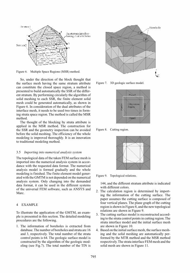
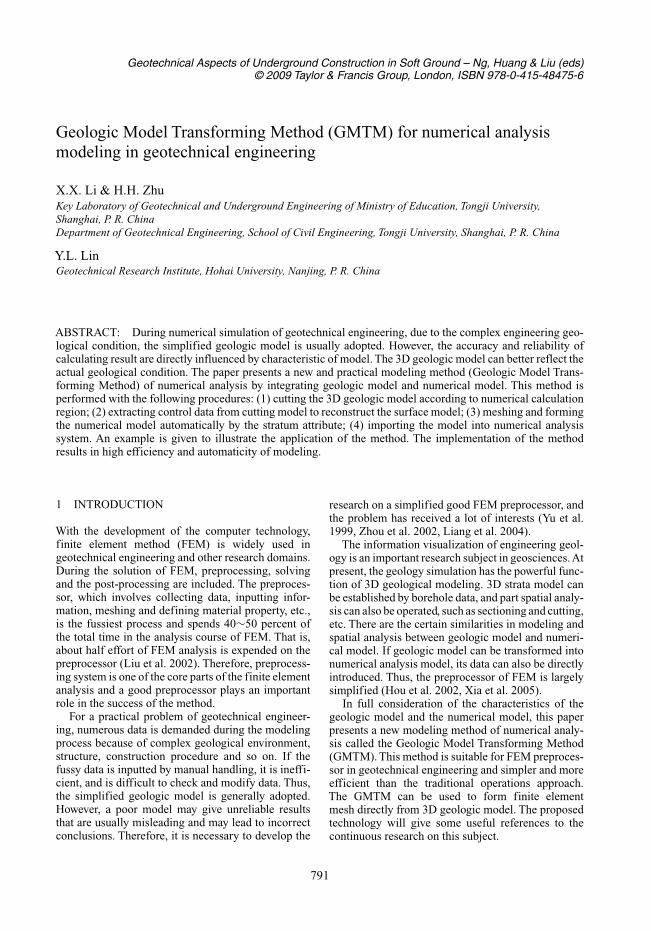
Figure 6. Multiple Space Regions (MSR) method.
So, under the direction of the block thought thatthe surface mesh having the same stratum attributecan constitute the closed space region, a method ispresented to build automatically the SSR of the differ-ent stratum. By performing circularly the algorithm ofsolid meshing to each SSR, the finite element solidmesh could be generated automatically, as shown inFigure 6. In consideration of the dual attributes of theinterface mesh, it needs to be used two times in form-ing strata space region. The method is called the MSRmethod.
The thought of the blocking by strata attribute isapplied in the MSR method. The construction forthe SSR and the geometry inspection can be avoidedbefore the solid meshing. The efficiency of the wholemodeling is improved thoroughly. It is an innovationto traditional modeling method.
3.5 Importing into numerical analysis system
The topological data of the taken FEM surface mesh isimported into the numerical analysis system in accor-dance with the requested data format. The numericalanalysis model is formed gradually and the wholemodeling is finished. The finite element model gener-ated with the GMTM is not depended on the numericalanalysis system. Only changing into the demandeddata format, it can be used in the different systemsof the universal FEM software, such as ANSYS andMarc.
4 EXAMPLE
To illustrate the application of the GMTM, an exam-ple is presented in this section. The detailed modelingprocedures are the following.
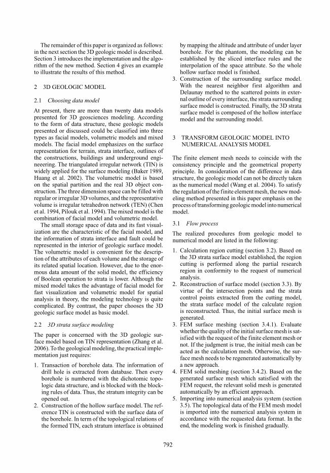
1. The information of boreholes is extracted fromdatabase.The number of boreholes and strata are 16and 3, respectively. The total number of the stratacontrol points is 64. The geologic surface model isconstructed by the algorithm of the geologic mod-eling (see Fig.7). The total number of the TIN is
Figure 7. 3D geologic surface model.
Figure 8. Cutting region.
Figure 9. Topological relations.
144, and the different stratum attribute is indicatedwith different colors.
2. The calculation region is determined by import-ing the information of the cutting surface. Thepaper assumes the cutting surface is composed offour vertical planes. The plane graph of the cuttingregion is shown in Figure 8, and the new topologicalrelations are shown in Figure 9.
3. The cutting surface model is reconstructed accord-ing to the strata control points in cutting region.Thestrata interface model and the initial surface meshare shown in Figure 10.
4. Based on the initial surface mesh, the surface mesh-ing and the solid meshing are automatically per-formed by the MTR method and the MSR methodrespectively.The strata interface FEM mesh and thesolid mesh are shown in Figure 11.
795

Figure 10. Surface model: (a) strata interface model;(b) initial surface mesh.
Figure 11. FEM mesh: (a) strata interface mesh; (b) solidmesh.
Figure 12. Mesh of the excavation model: (a) whole mesh;(b) part mesh.
5. The excavation process also can be simulated by theregion cutting. In this example, the cutting regionis taken as the foundation pit. The whole and partFEM mesh are shown in Figure 12. In the surfacemodel, the total number of the point and the triangleelement generated are 1140 and 3646 respectively.In the solid model, the total number of the pointand the tetrahedron element generated are 1821 and8838, respectively.The total time spent in the wholemodeling process is about 10 minutes.
Figure 13. Stress distribution: (a)before excavation;(b) after excavation.
6. The topological data of the formed mesh isimported into the FEM software Marc. In order tocheck the element mesh quality, a simple numeri-cal calculation is implemented. Figure 13 shows theself-weight stresses of the model before excavationand after excavation in the action of gravity.
5 CONCLUSIONS
In order to simplify the preprocessor of the numericalanalysis, the paper presents a new modeling methodbased on the geologic model. It differs from the tradi-tional modeling method. In our method, the numericalmodel is generated by the following procedures: cut-ting the calculation region, reconstructing the surfacemodel, finite element automatic meshing, importingthe analysis system. The characteristic of the methodis generalized as:
1. The element mesh is marked by the stratumattribute, so the model further nears to the realgeological condition. The partial region can be ran-domly extracted from the 3D strata model, and mustnot be established repeatedly.
2. Taking the advantage of the characteristic of thegeologic model, the complex meshing algorithm isavoided. The programming of the meshing is sim-ple and efficient. The whole modeling is highlyautomatic and rapid.
3. The excavation of the foundation and the tunnelcan be conveniently simulated. The boundary ofthe excavation must not be set in advance.
4. The finite element mesh can be imported into thedifferent analysis system to calculate. The model isapplicable and flexible.
5. In a word, the GMTM realizes the dream to estab-lish numerical model directly based on 3D geologicmodel. It provides a nice possibility and prospectfor FEM numerical simulation. The transformingmethod based on other geologic model is consis-tent with the method presented in the paper, but thematerial algorithm needs to be studied further.
796

REFERENCES
Baker, T.J. 1989. Developments and trends in three dimen-sional mesh generation. Applied Numerical Mathematics.
Chen, X.Y. & Kozo, I. 1994. Three dimensional modelingof GIS based on delaunay tetrahedral tessellations. In:International Archives of Photogrammetry and RemoteSensing, Munich, Germany, 30: 132–139.
George, P.L. 1991. Automatic mesh Generation: Applicationto Finite Element Methods. Witey, New York.
Hou, E.K, Wu, L.X. & Li, J.M. 2002. Study on the couplingof 3D geoscience modeling with numerical simulation.Journal of China coal Society, 27(4): 388–392.
Huang, Y.Y. & Chen, S.Q. 2002. Geologic modeling bymarching cube. Journal of Engineering Graphics, 23(2):65–69.
Lau, T.S. & Lo, S.H. 1996. Finite element mesh generationover analytical curved surface. Computers & Structures,59(2): 301–309.
Liang, S.W, Yang X.H. & Yang, W.B. 2004. System integra-tion of ANYSIS preprocessor and AutoCAD. Journal ofHuazhong University of Science and Technology (UrbanScience Edition), 21(1): 81–84.
Liu, L.M, Liu, H.L. & Zhu, Z.D. 2002. Integration methodof geoengineering finite element analysis system based onGIS. Chinese Journal of Rock Mechanics and Engineer-ing, 21(Supp.1): 1995–1998.
Pilouk, M, Klaus, T. & Martien, M. 1994. A tetrahedron-based 3D vector data model for geoinformation.In: Advanced Geographic Data Modeling, Nether-lands Geodetic Commission, Publications on Geodesy,1994(40): 129–140.
Shephard, M.S. & Georges, M.K. 1991. Automatic threedimensional mesh generation by the finite octree tech-nique. International Journal for Numerical methods inEngineering, 32: 709–749.
Wang, C.X. & Bai, S.W. 2004. Study on integration of 3Dstrata information system and FEM. Chinese Journal ofRock Mechanics and Engineering, 23(21): 3695–3699.
Xia, Y.H, Bai, S.W. & Ni, C.S. 2005. Study on couplingof 3D visualization with numerical simulation for pow-erhouse excavation of a certain hydrojunction. Rock andSoil Mechanics, 26(6): 969–972.
Yu, C, Zhou, X.H. & Zhang, Y.Q. 1999. The integration ofthe feature-based modeling and finite element method.Journal of computer-aided design and computer graphics.
Zhang, F, Zhu, H.H. & Ning, M.X. 2006. Modeling methodof 3D strata suitable for massive data. Chinese Jour-nal of Rock Mechanics and Engineering, 25(Supp.1):3306–3310.
Zhou, E.H, Zhu, Y.W. & Wang, T. 2002. Transitional-zone method in hexahedral finite element meshing ingeotechnical engineering. Engineering Journal of WuhanUniversity, 35(3): 24–29.
797