genuine interior lighting kit - trademotion...1 genuine interior lighting kit installation...
TRANSCRIPT
1
GENUINE Interior Lighting Kit
INSTALLATION INSTRUCTIONS
Thank you for purchasing a genuine Mazda accessory. Before removal and installation, be sure to thoroughly read these instructions. Please read the contents of this booklet in order to properly install and use the interior lighting kit. Your safety depends on it. Keep these instructions with your vehicle records for future reference.
There are several WARNING and CAUTION sections in this booklet concerning safety when installing or removing the interior lighting kit. Always read and follow them in order to prevent injuries, accidents, and possible damage to the vehicle.
WARNING: Indicates a situation in which serious injury or death could result if the warning is ignored.
CAUTION: Indicates a situation in which bodily injury or damage to the vehicle could result if the caution is ignored.
For areas indicating the tightening torque in this instruction manual, tighten to the specified torque using a torque wrench.
Do not modify the interior lighting kit. Do not install the interior lighting kit remove in any way other than described in the following instructions. If in any doubt, please ask your Mazda dealer to install the accessory in order to prevent errors in
installation. If you have any questions about the use of the accessory, ask your Mazda dealer for proper advice
before using it. Mazda and its suppliers are not responsible for injuries, accidents, and damage to persons and property
that arise from the failure of the dealer or installer to follow these instructions. To ensure safety and reliability of the work, installation, removal and disposal work must be carried out
by an Authorized Mazda Dealership. Be careful not to lose removed parts, and be sure that they are kept free from scratches, grease or
other dirt.
PART NAME: Interior Lighting kit VEHICLE: MAZDA CX-5 PART NUMBER: KB7W V7 050
To the dealer Please turn over these instructions to the customer after installation. To the customer Keep these instructions after installation. The instructions may be necessary
for installing other optional parts or removal of this accessory. Should the vehicle or this accessory be resold, always leave these instructions
with vehicle for the next owner.
WARNING
NOTE
KB7W-V7-050-01_01
2
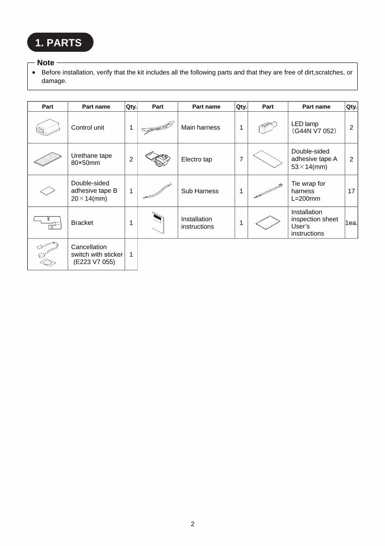
Part Part name Qty. Part Part name Qty. Part Part name Qty.
Control unit 1 Main harness 1
LED lamp (G44N V7 052) 2
Urethane tape 80×50mm 2
Electro tap 7
Double-sided adhesive tape A 53×14(mm)
2
Double-sided adhesive tape B 20×14(mm)
1 Sub Harness 1
Tie wrap for harness L=200mm
17
Bracket 1
Installation instructions
1
Installation inspection sheet User’s instructions
1ea.
Cancellation switch with sticker (E223 V7 055)
1
Before installation, verify that the kit includes all the following parts and that they are free of dirt,scratches, or damage.
Note
1. PARTS
3
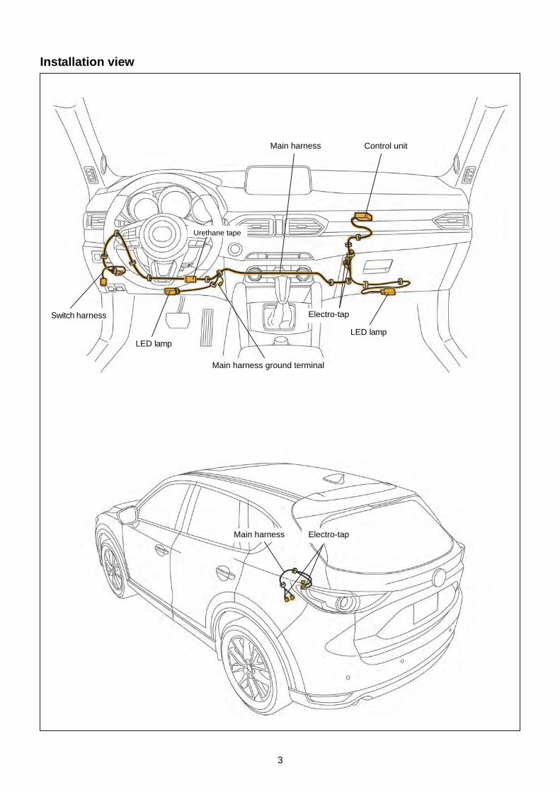
Installation view
Main harness
Switch harness
Main harness
LED lamp
Control unit
LED lamp
Electro-tap
Electro-tap
Main harness ground terminal
Urethane tape
4
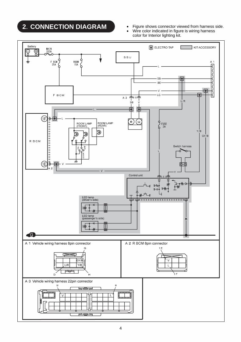
2.CONNECTION DIAGRAM Figure shows connector viewed from harness side.
Wire color indicated in figure is wiring harness color for Interior lighting kit.

5
■ REQUIRED TOOLS ☆Screwdriver (Phillips) ☆Socket wrench ☆Torque wrench
☆Nipper ☆Pliers ☆Pin
☆Drill (2mm,5mm,9mm) ☆Hole saw (20mm) ☆Round file
☆Flathead screwdriver wrapped with protective tape ☆Fastener remover wrapped with protective tape ☆Scissors
☆Masking tape ☆Electrical vinyl tape ☆Soft clean cloth
☆Mat ☆IPA (Isopropyl alcohol)
To perform the installation work safely and maintain functionality and quality, thoroughly read these instructions before performing the procedures and always heed the warnings and precautions.
In the work procedures, there are descriptions which are only indicated in the illustrations. Make sure to follow these procedures as well.
WARNING
When the negative battery is
connected during operation, may cause electric shock or other personal injuries. Disconnect the negative cable before /installation.
Before performing any work, park the vehicle on level ground, apply the parking brake securely, and then block the wheels.
Be careful when handling drills and other sharp objects. If not handled properly, it could result in serious injury.
When connecting/dis- connecting connectors, grasp the connectors, not the wires. Otherwise a short, and an accident from poor contact or fire may occur.
Make sure the connector is securely pressed in until a click sound is heard. Otherwise, a fire or other accident may occur due to an open circuit or poor contact.
Secure the harness with the band (part included) so it doesn’t dangle. If not, it may cause a short, accident, or fire.
Do not pull the harness with excessive force. Doing so can cause a breakage or a short-related accident, as well as an electrical short or fire.
CAUTION
Using improper tools may cause damage and/or broken parts. Use the correct tool for the job.
Wrap protective tape around screwdrivers and fastener remover tools to prevent scratching the vehicle.
Excessive length of tie wrap may interfere with other parts and cause damage.
Put the removed parts and the parts in the kit on the protective sheet to prevent scratches.
If there is dust, dirt or grease on the adhesion surface, the adhesive strength of the double-sided adhesive tape will splotch and adhesive power of the tape will be reduced. Wash and degrease the surface of the adhesion area before applying the double-sided adhesive tape. Be sure to wash interior and exterior parts using IPA (isopropyl alcohol).
If tape or a mount base is re-adhered, the adhesive strength will be weakened. Before adhering, accurately determine the adhesion position.
When drilling, hold the drill or hole saw perpendicular to the drilling surface to prevent the drill position from deviating.
Make sure to remove burrs fromthe surface so that the bumper surface is smooth.
Advice Refer to the Workshop Manual for removal and installation of vehicle parts.
3. BEFORE INSTALLATION

6
■ Branch connection procedure using electro tap
1. Insert the harness and vehicle wiring harness into
the electro tap.
2. Fold the electro tap as shown in the figure and lock it.
3. Insert the harness to the end of the electro tap.
4. Firmly press the electro tap terminal using pliers.
5. Fold the electro tap in the direction of the arrow
shown in the figure and lock it.
Firmly engage the lock part until a click sound is heard.
CAUTION
Electro tap
Harness
Firmly press using pliers
Vehicle wiring harness
Lock
Lock
Vehicle wiring harness
Terminal
Vehicle wiring harness
7
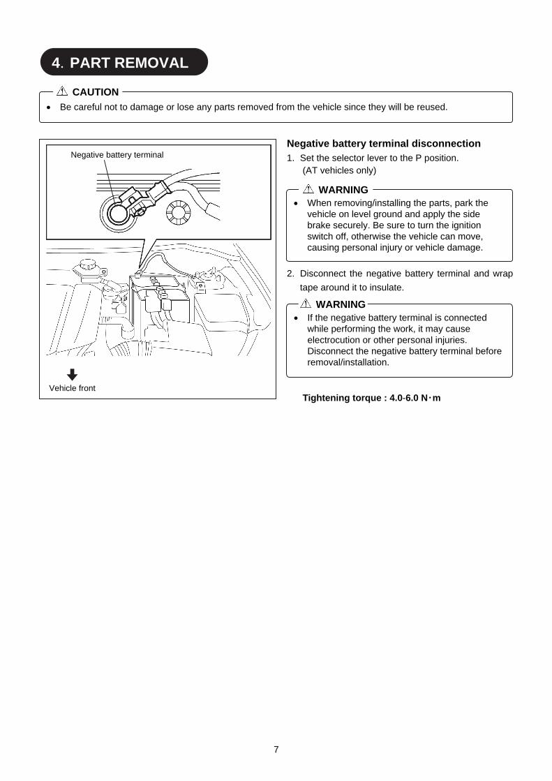
Negative battery terminal disconnection 1. Set the selector lever to the P position.
(AT vehicles only)
2. Disconnect the negative battery terminal and wrap
tape around it to insulate.
Tightening torque : 4.0-6.0 N・m
4.PART REMOVAL
Be careful not to damage or lose any parts removed from the vehicle since they will be reused.
CAUTION
When removing/installing the parts, park the vehicle on level ground and apply the side brake securely. Be sure to turn the ignition switch off, otherwise the vehicle can move, causing personal injury or vehicle damage.
WARNING
If the negative battery terminal is connected while performing the work, it may cause electrocution or other personal injuries. Disconnect the negative battery terminal before removal/installation.
WARNING
Vehicle front
Negative battery terminal

8
Front scuff plate removal 1. Hold area A shown in the figure, open the front
scuff plate in the direction of arrow (1), and detach
tab A of the front scuff plate from the inner panel
while moving it in the direction of arrow (2). 2. Hold the shaded areas shown in the figure and
detach tab B of the front scuff plate from the inner
panel while moving the front scuff plate in the
direction of arrow (3).
3. Hold area A shown in the figure, open the front
scuff plate in the direction of arrow (1), and detach
tab A of the front scuff plate from the inner panel
while moving it in the direction of arrow (2).
4. Hold the shaded areas shown in the figure and
detach tab B of the front scuff plate from the inner
panel while moving the front scuff plate in the
direction of arrow (3).
Vehicle front
: Tab B
(1)
Inner panel
Area A
(3)
(2)
Inner panel
Tab A
Front scuff plate
Illustration indicates left side. (RH side identical)
Front scuff plate
Front scuff plateInner panel
Tab A (2)
(3)
: Tab B
Vehicle front
Illustration indicates left side. (RH side identical)
(1)
Area A
Inner panel
Front scuff plate
9
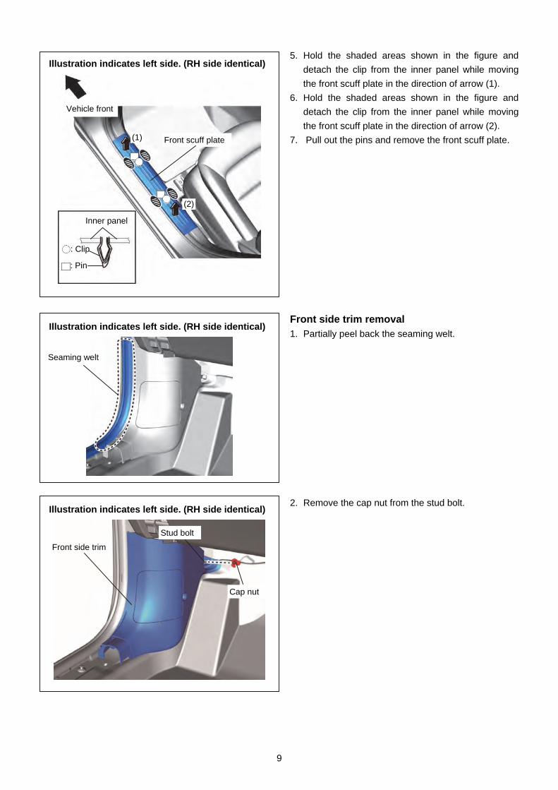
5. Hold the shaded areas shown in the figure and
detach the clip from the inner panel while moving
the front scuff plate in the direction of arrow (1).
6. Hold the shaded areas shown in the figure and
detach the clip from the inner panel while moving
the front scuff plate in the direction of arrow (2).
7. Pull out the pins and remove the front scuff plate.
Front side trim removal 1. Partially peel back the seaming welt.
2. Remove the cap nut from the stud bolt.
Seaming welt
Illustration indicates left side. (RH side identical)
Front side trim
Stud bolt
Cap nut
Illustration indicates left side. (RH side identical)
Illustration indicates left side. (RH side identical)
Front scuff plate
Inner panel
: Clip
: Pin
Vehicle front
(1)
(2)
10
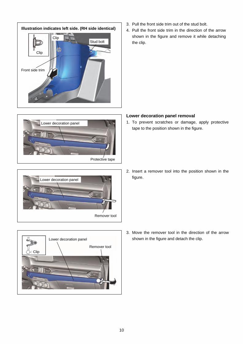
3. Pull the front side trim out of the stud bolt.
4. Pull the front side trim in the direction of the arrow
shown in the figure and remove it while detaching
the clip.
Lower decoration panel removal 1. To prevent scratches or damage, apply protective
tape to the position shown in the figure.
2. Insert a remover tool into the position shown in the
figure.
3. Move the remover tool in the direction of the arrow
shown in the figure and detach the clip.
Illustration indicates left side. (RH side identical)
Clip
Clip Stud bolt
Front side trim
Lower decoration panel
Protective tape
Lower decoration panel
Remover tool
: Clip
Lower decoration panel
Remover tool
11
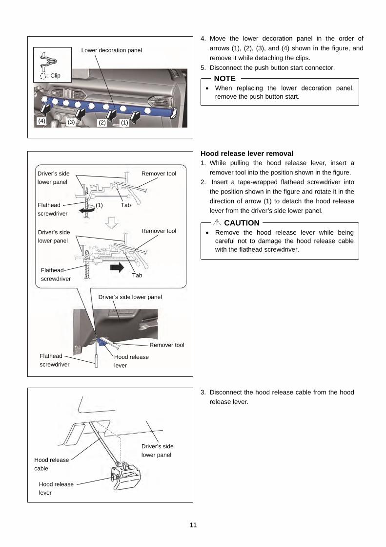
4. Move the lower decoration panel in the order of
arrows (1), (2), (3), and (4) shown in the figure, and
remove it while detaching the clips.
5. Disconnect the push button start connector.
Hood release lever removal 1. While pulling the hood release lever, insert a
remover tool into the position shown in the figure.
2. Insert a tape-wrapped flathead screwdriver into
the position shown in the figure and rotate it in the
direction of arrow (1) to detach the hood release
lever from the driver’s side lower panel.
3. Disconnect the hood release cable from the hood
release lever.
Remove the hood release lever while being careful not to damage the hood release cable with the flathead screwdriver.
CAUTION
When replacing the lower decoration panel, remove the push button start.
NOTE
Driver’s side
lower panel Hood release
cable
Hood release
lever
Driver’s side lower panel
Tab
Remover tool
(1) Flathead
screwdriver
Driver’s side
lower panel
Flathead
screwdriver Tab
Remover tool
Flathead
screwdriver Hood release
lever
Remover tool
Driver’s side
lower panel
Lower decoration panel
: Clip
(1) (2) (3) (4)
12
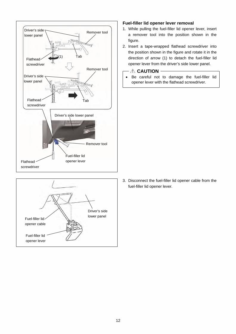
Fuel-filler lid opener lever removal 1. While pulling the fuel-filler lid opener lever, insert
a remover tool into the position shown in the
figure.
2. Insert a tape-wrapped flathead screwdriver into
the position shown in the figure and rotate it in the
direction of arrow (1) to detach the fuel-filler lid
opener lever from the driver’s side lower panel.
3. Disconnect the fuel-filler lid opener cable from the
fuel-filler lid opener lever.
Be careful not to damage the fuel-filler lid opener lever with the flathead screwdriver.
CAUTION
Driver’s side
lower panel
Tab
Remover tool
Flathead
screwdriver
(1)
Driver’s side
lower panel
Flathead
screwdriver Tab
Remover tool
Flathead
screwdriver
Fuel-filler lid
opener lever
Remover tool
Driver’s side lower panel
Driver’s side
lower panel Fuel-filler lid
opener cable
Fuel-filler lid
opener lever
13
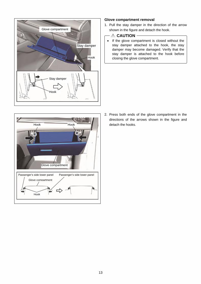
Glove compartment removal 1. Pull the stay damper in the direction of the arrow
shown in the figure and detach the hook.
2. Press both ends of the glove compartment in the
directions of the arrows shown in the figure and
detach the hooks.
If the glove compartment is closed without the stay damper attached to the hook, the stay damper may become damaged. Verify that the stay damper is attached to the hook before closing the glove compartment.
CAUTION
Hook
Glove compartment
Stay damper
Hook
Stay damper
Passenger’s side lower panel
Glove compartment
Passenger’s side lower panel
Hook
Hook Hook
Glove compartment

14
3. Lower the glove compartment in the direction of
arrow (1) shown in the figure, pull it up in the
direction of arrow (2), and remove it while detaching
the hooks.
Glove compartment
Passenger’s side lower panel
Hook
(1)
(2)
Glove compartment
Hook
(1)
(2)
15
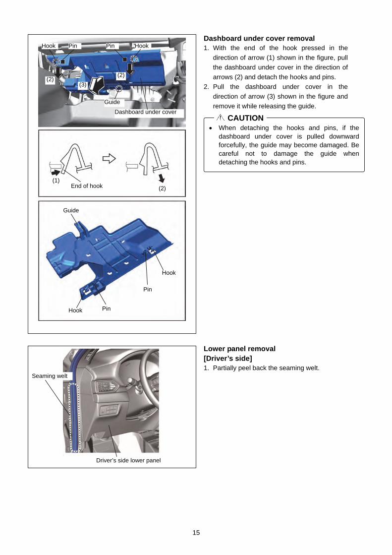
Dashboard under cover removal 1. With the end of the hook pressed in the
direction of arrow (1) shown in the figure, pull
the dashboard under cover in the direction of
arrows (2) and detach the hooks and pins.
2. Pull the dashboard under cover in the
direction of arrow (3) shown in the figure and
remove it while releasing the guide.
Lower panel removal [Driver’s side] 1. Partially peel back the seaming welt.
Seaming welt
Driver’s side lower panel
When detaching the hooks and pins, if the dashboard under cover is pulled downward forcefully, the guide may become damaged. Be careful not to damage the guide when detaching the hooks and pins.
CAUTION
End of hook (1)
(2)
Hook Pin
Dashboard under cover
Guide
Pin Hook
(2) (2)
(3)
Hook Pin
Pin
Hook
Guide

16
2. Remove the bolt.
3. Pull the driver’s side lower panel in the order of
arrows (1), (2), (3), and (4) shown in the figure,
and remove it while detaching the clips, hook, tab,
and guide.
Driver’s side lower panel
Dashboard
: Clip
: Hook
: Tab
: Guide
Dashboard
Dashboard
Dashboard
(1) (2) (3)
(4)
Bolt
Driver’s side lower panel
Bolt: 2.0—6.0 N·m {21—61 kgf·cm, 18—63 in·lbf}

17
4. Disconnect the cluster switch connector.
5. Remove the data link connector.
6. Remove the wiring harness clips A and B.
[Passenger’s side] 1. Partially peel back the seaming welt.
2. Remove the bolts.
3. Remove the screws.
Passenger’s side lower panel
Seaming welt
Passenger’s side lower panel
Bolt
Screw Screw
Bolt
: Wiring harness clip A
: Wiring harness clip B
Wiring harness clip A
Wiring harness clip B
Cluster switch connector
Data link connector
Driver’s side lower panel
18
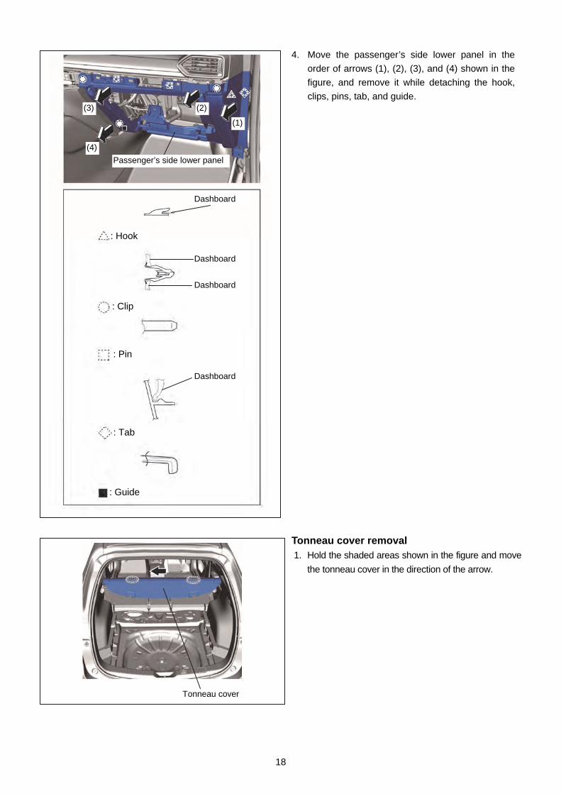
4. Move the passenger’s side lower panel in the
order of arrows (1), (2), (3), and (4) shown in the
figure, and remove it while detaching the hook,
clips, pins, tab, and guide.
Tonneau cover removal 1. Hold the shaded areas shown in the figure and move
the tonneau cover in the direction of the arrow.
Dashboard
: Hook
Dashboard
Dashboard
: Pin
: Clip
: Tab
: Guide
Dashboard
Passenger’s side lower panel
(1)
(2) (3)
(4)
Tonneau cover

19
2. Remove the tonneau cover in the direction of the
arrow shown in the figure.
Trunk board removal 1. Remove the center trunk board.
Center trunk board
Move the center trunk board in the direction of the arrows shown in the figure, and remove the ends of the center trunk board from the gap between the trunk side trim and the rear seat back.
Note
Tonneau cover
End of center trunk board
End of center trunk board
Rear seat back
Trunk side trim
Rear seat back
Trunk side trim
Rear seat back
Trunk side trim Trunk side trim
Center trunk board
20
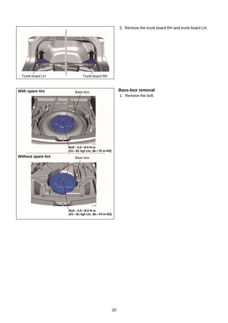
2. Remove the trunk board RH and trunk board LH.
Bass-box removal 1. Remove the bolt.
Trunk board RHTrunk board LH
Bolt : 4.0—8.0 N·m {41—81 kgf·cm, 36—70 in·lbf}
Bolt : 4.0—8.0 N·m {41—81 kgf·cm, 36—70 in·lbf}
With spare tire
Without spare tire
Bass box
Bass box
21
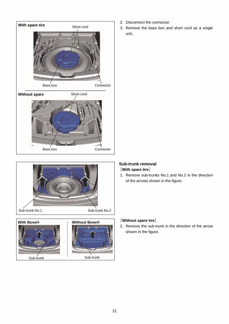
2. Disconnect the connector.
3. Remove the bass box and short cord as a single
unit.
Sub-trunk removal [With spare tire]
1. Remove sub-trunks No.1 and No.2 in the direction
of the arrows shown in the figure.
[Without spare tire]
2. Remove the sub-trunk in the direction of the arrow
shown in the figure.
Sub-trunk No.1 Sub-trunk No.2
With spare tire Short cord
Without spare
ConnectorBass box
ConnectorBass box
Short cord
Without Bose®With Bose®
Sub-trunk Sub-trunk
22
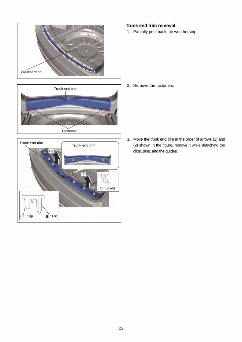
Trunk end trim removal 1. Partially peel back the weatherstrip.
2. Remove the fasteners.
3. Move the trunk end trim in the order of arrows (1) and
(2) shown in the figure, remove it while detaching the
clips, pins, and the guides.
Weatherstrip
Fastener
Trunk end trim
Trunk end trim
Trunk end trim
: Guide
: Clip : Pin
(1)
(2)
23
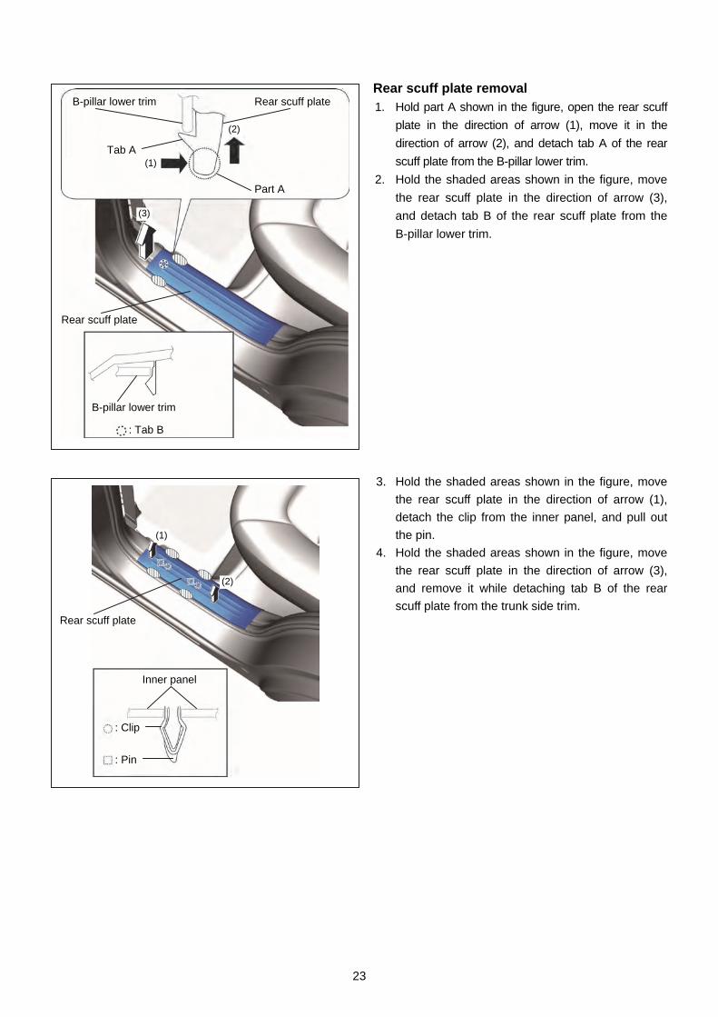
Rear scuff plate removal 1. Hold part A shown in the figure, open the rear scuff
plate in the direction of arrow (1), move it in the
direction of arrow (2), and detach tab A of the rear
scuff plate from the B-pillar lower trim.
2. Hold the shaded areas shown in the figure, move
the rear scuff plate in the direction of arrow (3),
and detach tab B of the rear scuff plate from the
B-pillar lower trim.
3. Hold the shaded areas shown in the figure, move
the rear scuff plate in the direction of arrow (1),
detach the clip from the inner panel, and pull out
the pin.
4. Hold the shaded areas shown in the figure, move
the rear scuff plate in the direction of arrow (3),
and remove it while detaching tab B of the rear
scuff plate from the trunk side trim.
(1)
(2)
Rear scuff plate
Inner panel
: Clip
: Pin
B-pillar lower trim
B-pillar lower trim
Rear scuff plate
Rear scuff plate
Tab A
Part A
(2)
(3)
(1)
: Tab B
24
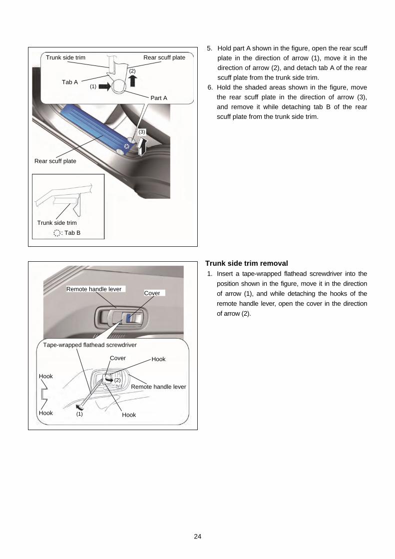
5. Hold part A shown in the figure, open the rear scuff
plate in the direction of arrow (1), move it in the
direction of arrow (2), and detach tab A of the rear
scuff plate from the trunk side trim.
6. Hold the shaded areas shown in the figure, move
the rear scuff plate in the direction of arrow (3),
and remove it while detaching tab B of the rear
scuff plate from the trunk side trim.
Trunk side trim removal 1. Insert a tape-wrapped flathead screwdriver into the
position shown in the figure, move it in the direction
of arrow (1), and while detaching the hooks of the
remote handle lever, open the cover in the direction
of arrow (2).
Tape-wrapped flathead screwdriver
Hook
Hook
Remote handle leverCover
Cover Hook
(2)
Hook
Remote handle lever
(1)
Rear scuff plate
(2)
Tab A
Part A
: Tab B
Trunk side trim
(1)
(3)
Trunk side trim
Rear scuff plate
25
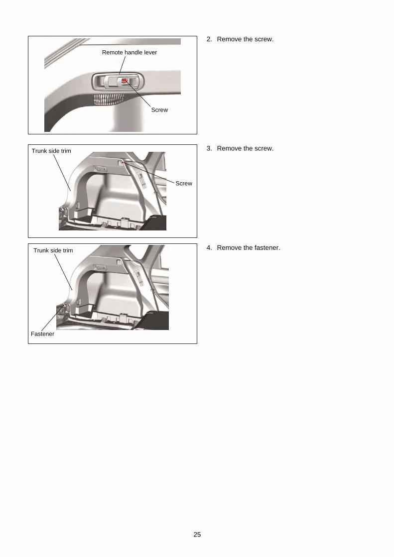
2. Remove the screw.
3. Remove the screw.
4. Remove the fastener.
Remote handle lever
Screw
Screw
Trunk side trim
Trunk side trim
Fastener

26
5. Remove the bolts.
6. Remove the cargo net hooks.
7. Partially peel back the weatherstrips.
8. Remove the rear seat cushion.
9. Fold the rear seat back.
10. Insert a tape-wrapped flathead screwdriver into
the position shown in the figure, move it in the
direction of the arrows, and remove the clips.
Weatherstrip Weatherstrip
Tape-wrapped flathead screwdriver
: clip
Trunk side trim
Bolt : 9—12 N·m {92—122 kgf·m, 80—106 ft·lbf}
Cargo net hook
Trunk side trim
Bolt
Cargo net hook
Bolt

27
11. Move the trunk side trim in the order of arrows (1),
(2), (3), and (4) shown in the figure, and remove
the clips and hooks.
12. Insert a hand into the back side of the trunk side
trim, press the tabs of the remote handle lever in
the direction of arrows (1) shown in the figure,
and remove the remote handle lever in the
direction of arrow (2).
13. Set the remote handle lever aside.
Tab
Trunk side trim
Remote handle lever
Trunk side trim
(1)
(1)
(2)
Tab
Tab
Remote handle lever
Remote handle lever
Trunk side trim
: clip : Hook
(1)
(2)
(3)
(4)
Left side only
28
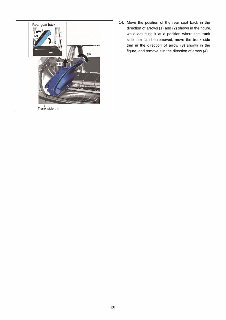
14. Move the position of the rear seat back in the
direction of arrows (1) and (2) shown in the figure,
while adjusting it at a position where the trunk
side trim can be removed, move the trunk side
trim in the direction of arrow (3) shown in the
figure, and remove it in the direction of arrow (4).
Trunk side trim
Rear seat back
(1)
(2)
(3)
(4)
29
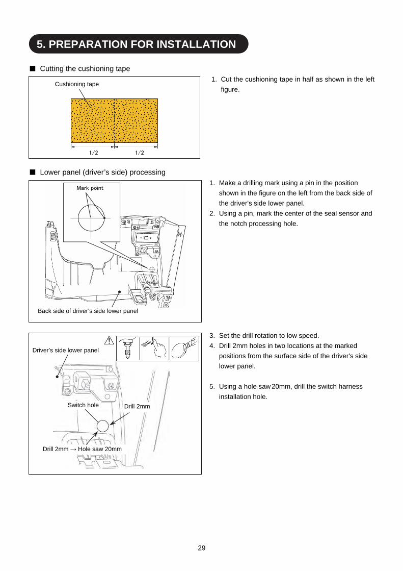
■ Cutting the cushioning tape
1. Cut the cushioning tape in half as shown in the left
figure.
■ Lower panel (driver’s side) processing
1. Make a drilling mark using a pin in the position
shown in the figure on the left from the back side of
the driver's side lower panel.
2. Using a pin, mark the center of the seal sensor and
the notch processing hole.
3. Set the drill rotation to low speed.
4. Drill 2mm holes in two locations at the marked
positions from the surface side of the driver's side
lower panel.
5. Using a hole saw 20mm, drill the switch harness
installation hole.
5. PREPARATION FOR INSTALLATION
Back side of driver’s side lower panel
Mark point
Drill 2mm
Driver’s side lower panel
Switch hole
Drill 2mm → Hole saw 20mm
Cushioning tape
1/2 1/2
30
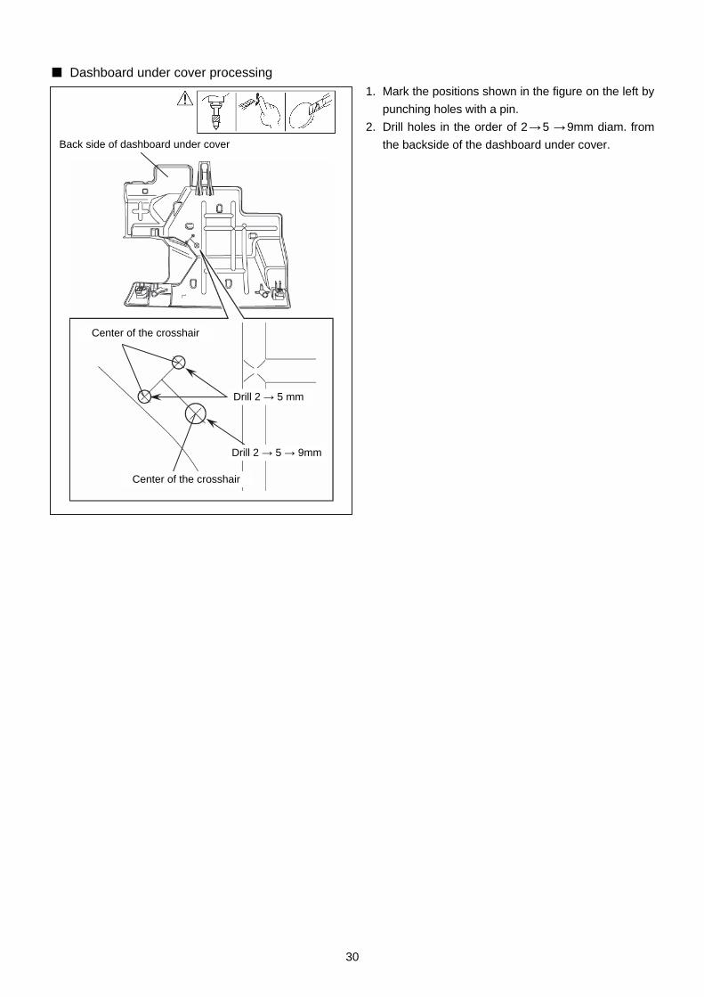
■ Dashboard under cover processing
1. Mark the positions shown in the figure on the left by
punching holes with a pin.
2. Drill holes in the order of 2 → 5 → 9mm diam. from
the backside of the dashboard under cover.
Back side of dashboard under cover
Center of the crosshair
Center of the crosshair
Drill 2 → 5 mm
Drill 2 → 5 → 9mm
31
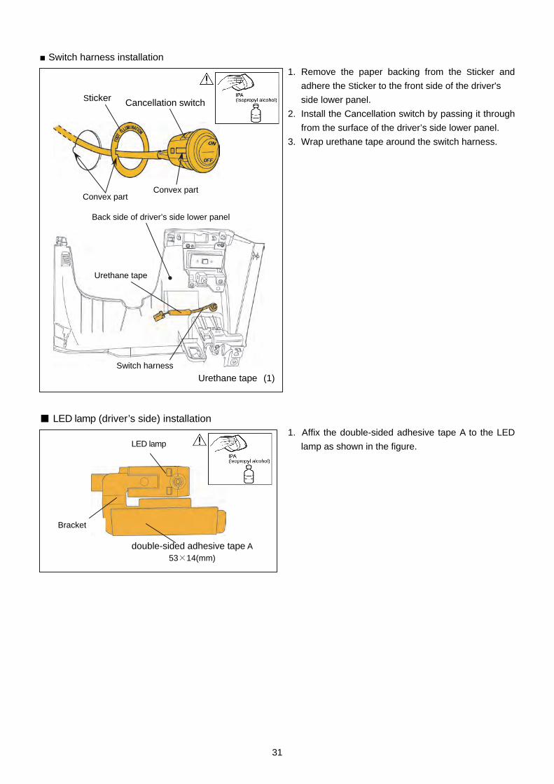
■ Switch harness installation
1. Remove the paper backing from the Sticker and
adhere the Sticker to the front side of the driver's
side lower panel.
2. Install the Cancellation switch by passing it through
from the surface of the driver’s side lower panel.
3. Wrap urethane tape around the switch harness.
■ LED lamp (driver’s side) installation 1. Affix the double-sided adhesive tape A to the LED
lamp as shown in the figure.
double-sided adhesive tape A
53×14(mm)
Bracket
LED lamp
Cancellation switch
Convex part
Sticker
Convex part
Switch harness
Back side of driver’s side lower panel
Urethane tape (1)
Urethane tape
32
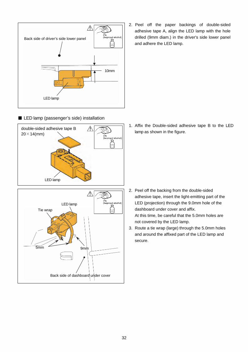
2. Peel off the paper backings of double-sided
adhesive tape A, align the LED lamp with the hole
drilled (9mm diam.) in the driver's side lower panel
and adhere the LED lamp.
■ LED lamp (passenger’s side) installation
1. Affix the Double-sided adhesive tape B to the LED
lamp as shown in the figure.
2. Peel off the backing from the double-sided
adhesive tape, insert the light-emitting part of the
LED (projection) through the 9.0mm hole of the
dashboard under cover and affix.
At this time, be careful that the 5.0mm holes are
not covered by the LED lamp.
3. Route a tie wrap (large) through the 5.0mm holes
and around the affixed part of the LED lamp and
secure.
LED lamp
Back side of driver’s side lower panel
double-sided adhesive tape B 20×14(mm)
LED lamp
Back side of dashboard under cover
Tie wrap
LED lamp
9mm 5mm
10mm
33
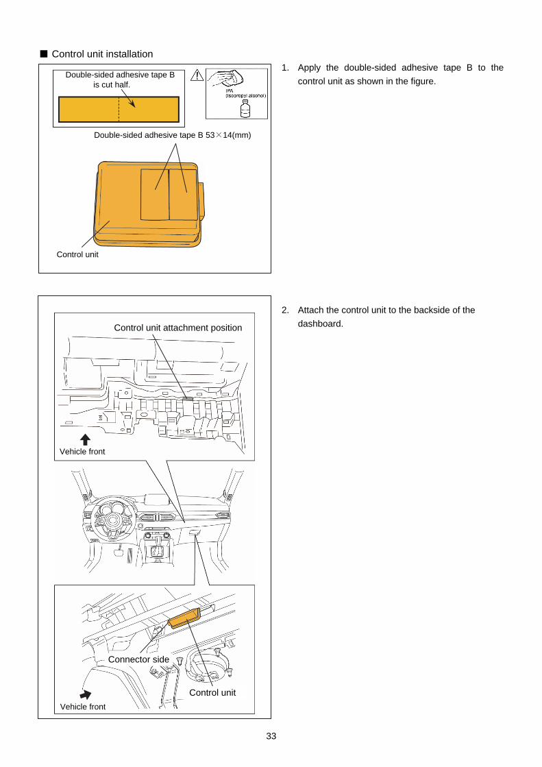
■ Control unit installation 1. Apply the double-sided adhesive tape B to the
control unit as shown in the figure.
2. Attach the control unit to the backside of the
dashboard.
Control unit
Double-sided adhesive tape B is cut half.
Double-sided adhesive tape B 53×14(mm)
Control unit
Control unit attachment position
Vehicle front
Vehicle front
Connector side

34
6.INSTALLATION OF MAIN HARNESSES
Connect an electro-tap to the indicated signal line securely. Misconnection may cause a system or vehicle malfunction.
Wrap the electro-tap area using cushioning tape to prevent the occurrence of abnormal noise.
CAUTION
Passenger side air bag module
(A)
Control unit
Dashboard member
(Hole)
Vehicle front ▲ Tie wrap (2)
(1) Connect the main harness to the control unit.
Main harness
(2) Install the main harness.
(3) Tie redundant part using tie wrap.
To (B)
35
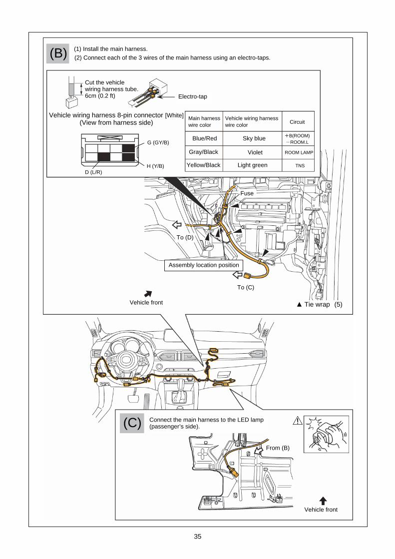
(B)
(C)
Vehicle front
Connect the main harness to the LED lamp (passenger’s side).
(1) Install the main harness. (2) Connect each of the 3 wires of the main harness using an electro-taps.
Cut the vehicle wiring harness tube. 6cm (0.2 ft)
Vehicle wiring harness 8-pin connector [White](View from harness side)
Vehicle front
▲ Tie wrap (5)
To (D)
To (C)
From (B)
G (GY/B)
H (Y/B)D (L/R)
Electro-tap
Assembly location position
Fuse
Main harnesswire color
Vehicle wiring harnesswire color
Circuit
Violet
Yellow/Black Light green
Sky blue
ROOM LAMP
TNS
Blue/Red
Gray/Black
+B(ROOM) -ROOM.L
36
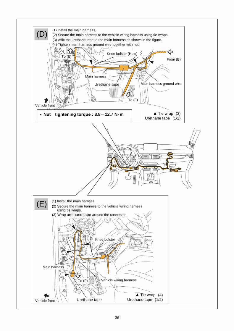
(E)
Main harness
(D)
(1) Install the main harness
(2) Secure the main harness to the vehicle wiring harnessusing tie wraps.
Vehicle wiring harness
Knee bolster (Hole)
(1) Install the main harness. (2) Secure the main harness to the vehicle wiring harness using tie wraps.
From (B)
To (F)
To (F)
Urethane tape
▲ Tie wrap (3) Urethane tape (1/2)
Nut tightening torque : 8.8-12.7 N・m
▲ Tie wrap (4)Urethane tape (1/2)
Knee bolster
Main harness
To (E)
(3) Wrap urethane tape around the connector.
Vehicle front
Vehicle front
Urethane tape
(3) Affix the urethane tape to the main harness as shown in the figure.(4) Tighten main harness ground wire together with nut.
Main harness ground wire

37
(F) (2) Connect the main harness to the LED lamp
(passenger’s side).
(1) Connect the main harness to the Cancellation switch.
From (E)
Cancellation switch
LED lamp (passenger’s side)
Driver’s side lower panel
From (E)
Vehicle front
38
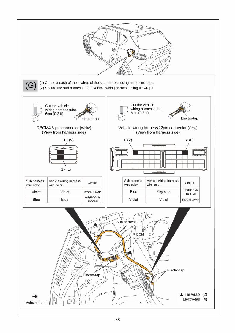
⑨
⑩
⑧
Cut the vehicle wiring harness tube. 6cm (0.2 ft)
Cut the vehiclewiring harness tube.6cm (0.2 ft)
RBCM4 8-pin connector [White] (View from harness side)
1E (V)
1F (L)
u (V) e (L)
Electro-tap Electro-tap
Electro-tap Electro-tap
Sub harness
R BCM
Vehicle front
Vehicle wiring harness 22pin connector [Gray] (View from harness side)
(1) Connect each of the 4 wires of the sub harness using an electro-taps.
(2) Secure the sub harness to the vehicle wiring harness using tie wraps.
▲ Tie wrap (2)Electro-tap (4)
(G)
Sub harness wire color
Vehicle wiring harness wire color
Circuit
Violet
Blue
Violet
Blue
ROOM LAMP
+B(ROOM)-ROOM.L
Sub harness wire color
Vehicle wiring harness wire color Circuit
Violet
Blue
Violet
Sky blue
ROOM LAMP
+B(ROOM)-ROOM.L

39
1. Reinstall parts in the reverse order of the installation procedure in【4.VEHICLE PARTS REMOVAL】.
2. Refer to “Required servicing after disconnecting/connecting negative battery cable” in the vehicle workshop
manual or the owner’s manual to restore the vehicle functions.
3. Perform reinstallation and inspection of the vehicle parts.
7.OPERATION CHECK