generator module agm20/30/35/ 40/50/70 - rinco ultrasonics · rinco ultrasonics ag romanshorn,...
TRANSCRIPT
Operating Manual
Generator Module
Engl
ish
AGM20/30/35/ 40/50/70

Copyright by RINCO ULTRASONICS AG, Switzerland
Version 4.0, gb, Art.-No. 35827
Creation date: 09.06.2010
DisclaimerThe information in this brochure corresponds to our current state of knowledge.However, it is not to be understood as a warranty for certain characteristics or for suitability of the products for certain applications. Our general contractual terms apply in this regard, and reference should also be made to these terms with regard to liability. No industrial property rights of any kind are granted to the user along with this brochure, nor are any assurances made with regard to a licence. Corresponding separate agreements would be necessary for this purpose. The suitability of the products for particular appli-cations may only be checked with our own specialists. The German version of the brochure is binding with regard to accuracy of the information given.

Notes
Read and precisely follow the information in this ope-rating manual before unpacking the unit and putting it into operation!
The unit may only be used, maintained and repairedby people, who are familiar with the operating manualand the applicable regulations on work safetyand accident prevention.
Unit-specific information
Agency

Content1 Explanation of symbols and signs 6
2 Transport 72.1 Receiving the delivery 72.2 Transport damage 7
3 Technical data 83.1 Engineer standards and conditions of use 83.2 Limit values, connection loads 8
4 Safety information 94.1 General information 94.2 Intended use 94.3 Use according to instructions 94.4 Installation 94.5 Electrical connection types 94.6 Operation 10
5 Installation 115.1 Mechanical installation 11
5.1.1 Measurement and assembling 115.2 Environmental conditions 125.3 Electrical installation 13
5.3.1 Power supply 135.3.2 Fuses / Cable cross-section 135.3.3 Earth conductor 145.3.4 Equipotential bonding 14
5.4 EMC-compliant installation 155.4.1 Installation of a CE typical ultrassonic system 155.4.2 Appropriate line filter for CE typical ultrasonic welding 15
6 Operation 166.1 High voltage 166.2 Acoustical noise 166.3 Damps and dust emission 166.4 Nois emission 166.5 Guarantee 17
7 Product information 187.1 Example of how to control the AGM generator module with accessories 187.2 Short overview of the functional
characteristigs 19
8 Available generator modules and theire variants 20
8.1 Output power classes 208.2 Suitable oscillator units 20
9 Operating and display elements 219.1 Connections of AGM generator 219.2 DIP switch for CAN Termianators 219.3 Mains voltage connection of generator module (STO_0) 21
9.3.1 connection 219.4 24V Integrated 24V power supply, CANopen interface and RS485 interface (STO1) 22
9.4.1 24V power supply 229.4.2 RS485 protocol 229.4.3 CANopen protocol 22
9.5 Signals (STO_2) 239.5.1 Description of signals 23
9.6 Connection to oscillator system (STO_4) 25
10 Operating modes 2610.1 Welding modes 26
10.1.1 Time mode 2610.1.2 Energy mode 2610.1.3 Continuous mode 26
10.2 Output and energy measurement 2710.2.1 Output measurement and output curve 2710.2.2 Power overload 2710.2.3 Energy measurement 27
10.3 Soft start, Soft stop and ramp start amplitude 2810.4 Ultrasonic test and power loss measurement 2910.5 Permitted frequency range 2910.6 Amplitude selection 29
11 Amplitude values 3011.1 Amplitude values, 20 kHz generators 30
11.1.1 Amplitude diagram of20 kHz generators 30
11.2 Amplitude values, 30 kHz generators 3111.2.1 Amplitude diagram of
30 kHz generators 3111.3 Amplitude values, 35 kHz generators 32
11.3.1 Amplitude diagram of35 kHz generators 32
11.4 Amplitude values, 40 kHz generators 3311.4.1 Amplitude diagram of
40 kHz generators 3311.5 Amplitude values, 70 kHz generators 34
11.5.1 Amplitude diagram of70 kHz generators 34
12 Operating parameters 35
13 Example applications 3613.1 Start and Stop Ultrasonic 3613.2 Amplitude selection 3813.3 Power measurement 4013.4 Error analysis 42
14 Technical data 4414.1 Power supply, 230 V 4414.2 Integrated 24VDC power supply 4414.3 Analog and digital inputs and outputs 44
14.3.1 Voltage supply and voltage level 4414.3.2 Overview of inputs and outputs 4514.3.3 Analog input and output 4614.3.4 Time behaviour of digital inputs and outputs 47
15 Cleaning and maintenance 51
16 Services internal components 51
17 Disposal 51
18 Error elimination 5218.1 General faults 52
19 Error messages 5319.1 Generator faults 5419.2 Converter and application faults 5519.3 Limit faults 56
20 Service Adresses 58

Important!When making inquiries about your machine, please quote the exact type and machine serial number.These can be found on the rating plate (A) as well as on the second page of this operating manual.The design and switchgear of these machines is the object of ongoing further development and improvement and correspond to the latest state of technology.
RINCO ULTRASONICS AGRomanshorn, Switzerland
PrefaceWe are very pleased that you chose to buy a RINCO product. We are convinced that you will achieve amaximum degree of economy of operation and pro-duct quality when using this unit.The purpose of this manual is to give the purchaserand the user all the information they need in termsof the handling, assembly, operation and care of the machine.To ensure that your system is always in an operationalstate, you should take note of and follow all thetips and instructions contained within this manual.
A

1 Explanation of symbols and signs
Please pay particular attention to sections of text with the following symbols:
Note!
Very important information or operational note on
how to weld properly with the ultrasonic equipment.
Caution!
Describes the serious hazards to the health of
people or damage to equipment that may result from
disregard.
Danger!
Describes dangers that may result in death or serious
bodily harm to people if disregarded.
Danger electricity!
Indicates a potential personal injury hazard. It
describes a danger of electricity or electric shock
and advise caution from a wide range of potential
danger.
Commandment!
Ear protectors must be worn. Shows the need to
wear safety equipment in the workplace.
6

2 Transport
Equipment may only be transported by suitably trai-
ned personnel.
Please note the transport advice on the packaging.
2.1 Receiving the delivery
The despatch containers for machines and equipment withstand normal loads during transport by road, rail and air.After receipt, please make sure that the all parts agree with the packaging list and that there is no visible damage. If damage is established, inform the transport company immediately and keep the packaging as proof.
2.2 Transport damage
The transport company is responsible for damage which occurs during transport. A complete report precisely describing the damage must be submitted to the transport company and serves as the basis for the claim for damages. Damage to or loss of goods supplied by us must be reported to us immediately and confirmed by a copy of the aforementioned report.If delivery by RINCO ULTRASONICS was free house or CIF, the damaged consignment will be replaced if appropriate and claims will be made to the relevant transport insurance company.
7

8
Typ HF power HF power HF power Mains supply Standby
Peak Pulsed- Continous- Voltage- Input-
operation operation frequency power
(1); (4) (2); (4) (3); (4) VA (max) VA (max)
AGM20-3000P-230-B2 3600W 2400W 1200W L1/N PE 230V 5200 48
AGM20-4-3000P-230-B2 50 / 60 Hz
207V --- 253V
AGM20-2000P-230-B2 2400W 1600W 1000W 3800 48
AGM20-4-2000P-230-B2
AGM20-1500P-230-B2 1800W 1200W 700W 2600 48
AGM20-4-1500P-230-B2
AGM20-1000P-230-B2 1200W 1000W 700W 2200 48
AGM20-4-1000P-230-B2
AGM30-1000P-230-B2 1200W 1000W 700W 2000 48
AGM30-500P-230-B2 600W 500W 400W 1100 48
AGM35-900P-230-B2 1080W 700W 500W 2000 48
AGM35-4-900P-230-B2
AGM35-600P-230-B2 720W 600W 500W 1500 48
AGM35-4-600P-230-B2
AGM35-400P-230-B2 480W 400W 400W 1100 48
AGM35-4-400P-230-B2
AGM40-800P-230-B2 960W 700W 500W 1900 48
AGM40-400P-230-B2 480W 400W 400W 1100 48
AGM50-100P-230-B1 120W 100W 100W 320 48
AGM70-100P-230-B1 120W 100W 100W 320 48
3 Technical data
3.1 Engineer standards and conditions of use
3.2 Limit values, connection loads
Conformity: CE
Admission: SEMIS2
Ambient conditions: - non-condensing, average relative humidity 20 to 90% - 0 to 1000 over NNTemperature range: transport/ -20 to +70 degree(Ambient temperature) storage
operation +10 to +50 degreeLeakage current: > 10 mA toward PESafety measures against: short-circuit, overload, excess temperature, final stageProtection system through housings: IP20
(1) Maximum peak power (im milliseconds)(2) Pulsed operatrion 1 to 9 (e.g. 1 s ON 9 s OFF)(3) At 100% ampiltude(4) These values are not to be understood as guarantee reference values of the AGM- generator. The values of an overall system can strongly deviate from it.

9
4 Safety information
4.1 General informationen
Some components of the ultrasonic system (HF cable, converter, horn) can be operated in such a way that they move or rotate.
Unauthorized removal of the required cover, impro-
per use and improper installation or operation can
cause serious personal or property damage.
All activities during transport, installation, commissio-ning and maintenace must be performed by qualified and trained personnel (IEC 364 and CENELEC HD 384 or DIN VDE 0100 and IEC-Report 664 or DIN VDE 0110 and national accident prevention regulations must be considered).According to this basic safety information, qualified and skilled personnel are persons who are familiar with the installation, the assembly, commissioning, and the operation of the product and have the qualifi-cations necessary for their occupation.
4.2 Indtended use
The AGM generators as well as the acessories are intended exclusively for the welding and cutting of suitable materials.Depending on material and application, there can be a developement of harmful vapors, material abrasion, high temperatures at material and tools as well as a high noise pollution. In this case provide appropriate retaliatory actions such as covers, sound enclosures, fire-extinguishing systems so that the endangerment for persons can be excluded. Please ask your material supplier about possible endangering which are caused by ultrasonic welding and cutting.For further information about suitable materails, please contact your RINCO ULTRASONICS AG, Switzerland.
4.3 Use according to instructions
AGM generators are components which have been designed for the installation in electrical systems or machinery. They may not be used as separate units. In accordance with EN 61000-3-2, they are meant ex-
clusively for professional and commercial use.This document contains information for compliance with the standard EN 61000-3-2.During the installation of AGM generators into a machine, the starting up (i.e. the start of operation as prescribed) is prohibited until it has been demonstra-ted that the machine corresponds to the EC directives 2006/42 EC (machinary directives) and the harmonized standard EN 60204-1 is mantained.The starting up (i.e. the start of operation as prescri-bed) is only permissible if the EMC directives 2004/108 EC are mantained.AGM-generators meet the requirements of the low-voltage directive 2006/95 EC and the harmonised norms of the series EN 61010-1 are valid.
4.4 InstallationProvide for appropiate handling and avoid excessive mechanical load. Do not bend any components and do not change any insulation distances during transport or handling. Do not affect electronic components. Only trained staff instructed in the use of the machine may work with the generator.AGM-generators contain electrostatically sensitive components which can be easily damaged by mistre-ating. Do not damage any electrical components or destory since thereby your health could be endangered!
4.5 Electrical connection types
If work on energized AGM-generators is carried out, the valid national accident prevention instructions (e.g. BGV A3) must be adhered.The electrical installation must be in accordance with the valid regulations (e.g. cable cross-sections, fuses, PE connection).Additional information can be found in the documen-tation.The documentation contains information about the installation according to the EMC directives (shielding, earthing, filters and cables).

4.6 Operation
Systems with AGM generators must be equipped with additional monitoring and safety device which corresponds to the valid standards (e.g. standards for technical equipment, accident prevention, etc.).Independently of it, an emergency stop circuit, a mains disconnect and an all-phase fuse protection of the input circuits is mandatory.
10
11
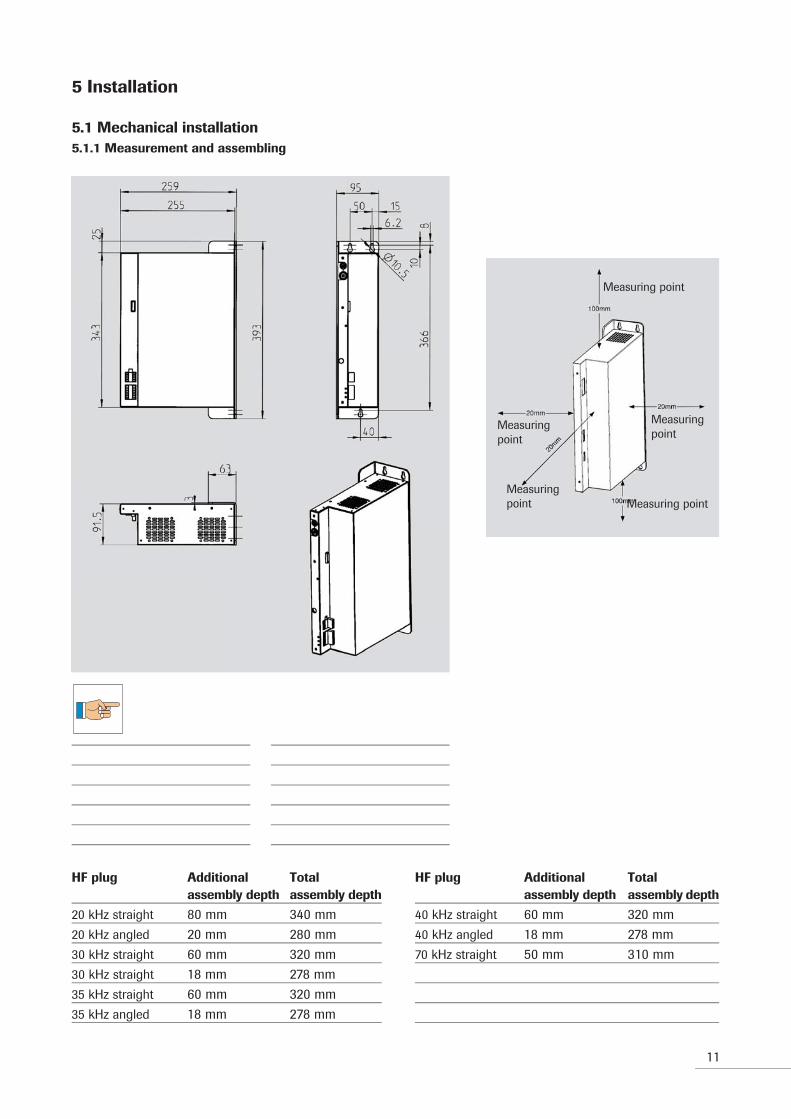
Measuring point
Measuringpoint
Measuring point
Measuringpoint
Measuringpoint
5 Installation
5.1 Mechanical installation5.1.1 Measurement and assembling
HF plug Additional Total assembly depth assembly depth
20 kHz straight 80 mm 340 mm20 kHz angled 20 mm 280 mm30 kHz straight 60 mm 320 mm30 kHz straight 18 mm 278 mm35 kHz straight 60 mm 320 mm35 kHz angled 18 mm 278 mm
HF plug Additional Total assembly depth assembly depth
40 kHz straight 60 mm 320 mm40 kHz angled 18 mm 278 mm70 kHz straight 50 mm 310 mm

12
5.2 Environmental conditions
AGM generators must not be installed at places where they are exposed to unfavorable environmental condi-tions. These includes:combustible, oily or harmful damps or dust, excessive humidity, extreme vibrations or temperatures.
For additional information, please contact directly RINCO ULTRASONICS AG Switzerland.
The function of the AGM generator is affected by the ambient temperature. The AGM generator must be installed in a way that the maximum allowable tempe-rature is in no case exceeded. The ambient tempera-ture must be controlled.The permissible ambient temperature goes from10 ° C to 50 ° C. If the required temperature can not be kept, an appropriate device (cooling, etc.) must be used. High-performance applications, continuous and virtually continuous applications should generally be cooled.The assembly is carried out with 3 x M4 or M5 steel screws. If correctly mounted, the assembly allows a fast device replacement during service.It is important to ensure that all three screws are pro-perly tightened during operation.

13
5.3 Electrical installtion5.3.1 Power supply
The AGM generator must be led across a bipolar
circuit breaker and an emergency stop.
5.3.2 Fuses / Cable cross-section (1)
(Short circuit current rating (SCCR) = 1,5kA)
Power connectionMachine Nom. Fuse Breaker (1/N PE AC 230V) output [mm²]AGM20-(4)-3000P-230-B2 3000 W M16 A C16 A min. 2.5
AGM20-(4)-2000P-230-B2 2000 W M16 A C16 A min. 2.5
AGM20-(4)-1500P-230-B2 1500 W M10 A C10 A min. 1.5
AGM20-(4)-1000P-230-B2 1000 W M10 A C10 A min. 1.5
AGM30-1000P-230-B2 1000 W M10 A C10 A min. 1.5
AGM30-500P-230-B2 500 W M6 A C6 A min. 1.5
AGM35-(4)-900P-230-B2 900 W M10 A C10 A min. 1.5
AGM35-(4)-600P-230-B2 600 W M6 A C6 A min. 1.5
AGM35-(4)-400P-230-B2 400 W M6 A C6 A min. 1.5
AGM40-800P-230-B2 800 W M10 A C10 A min. 1.5
AGM40-400P-230-B2 400 W M6 A C6 A min. 1.5
AGM50-100P-230-B1 100 W M6 A C6 A min. 1.5
AGM70-100P-230-B1 100 W M6 A C6 A min. 1.5(1) Please consider in each case the valid local regluations.

14
5.3.3 Earth conductor
The AGM generator must never be operated without a protective conductor connection. In addition, an earth conductor with min 2.5 mm² must be led from the AGM generator to each ultrasonic converter.
5.3.4 Equipotential bonding
Every component of an ultrasonic system must be connected to a equipotential bonding system of the machine (mfg.-plant). This connection can be made via a mounting plate, such as AGM generator and line filter, or via cable with a min of 6 mm².
15
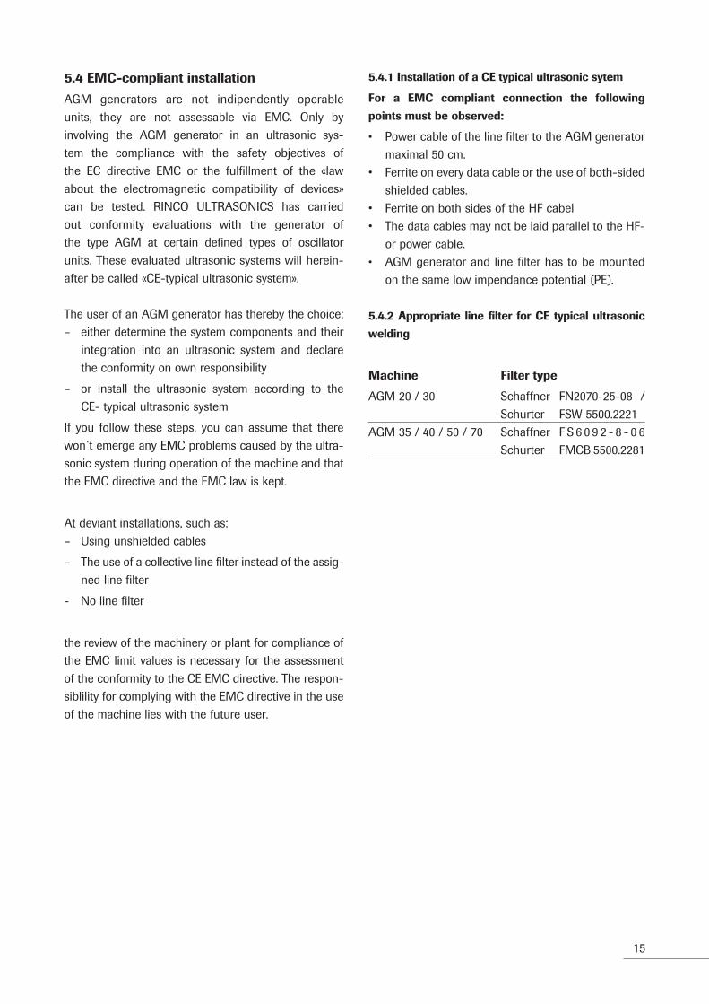
5.4 EMC-compliant installation
AGM generators are not indipendently operable units, they are not assessable via EMC. Only byinvolving the AGM generator in an ultrasonic sys-tem the compliance with the safety objectives of the EC directive EMC or the fulfillment of the «law about the electromagnetic compatibility of devices» can be tested. RINCO ULTRASONICS has carried out conformity evaluations with the generator of the type AGM at certain defined types of oscillatorunits. These evaluated ultrasonic systems will herein-after be called «CE-typical ultrasonic system».
The user of an AGM generator has thereby the choice:– either determine the system components and their
integration into an ultrasonic system and declare the conformity on own responsibility
– or install the ultrasonic system according to theCE- typical ultrasonic system
If you follow these steps, you can assume that there won`t emerge any EMC problems caused by the ultra-sonic system during operation of the machine and that the EMC directive and the EMC law is kept.
At deviant installations, such as:– Using unshielded cables
– The use of a collective line filter instead of the assig-ned line filter
- No line filter
the review of the machinery or plant for compliance of the EMC limit values is necessary for the assessment of the conformity to the CE EMC directive. The respon-siblility for complying with the EMC directive in the use of the machine lies with the future user.
5.4.1 Installation of a CE typical ultrasonic sytem
For a EMC compliant connection the following
points must be observed:
• Power cable of the line filter to the AGM generator maximal 50 cm.
• Ferrite on every data cable or the use of both-sided shielded cables.
• Ferrite on both sides of the HF cabel• The data cables may not be laid parallel to the HF-
or power cable.• AGM generator and line filter has to be mounted
on the same low impendance potential (PE).
5.4.2 Appropriate line filter for CE typical ultrasonic
welding
Machine Filter type
AGM 20 / 30 Schaffner FN2070-25-08 / Schurter FSW 5500.2221AGM 35 / 40 / 50 / 70 Schaffner F S 6 0 9 2 - 8 - 0 6 Schurter FMCB 5500.2281
16
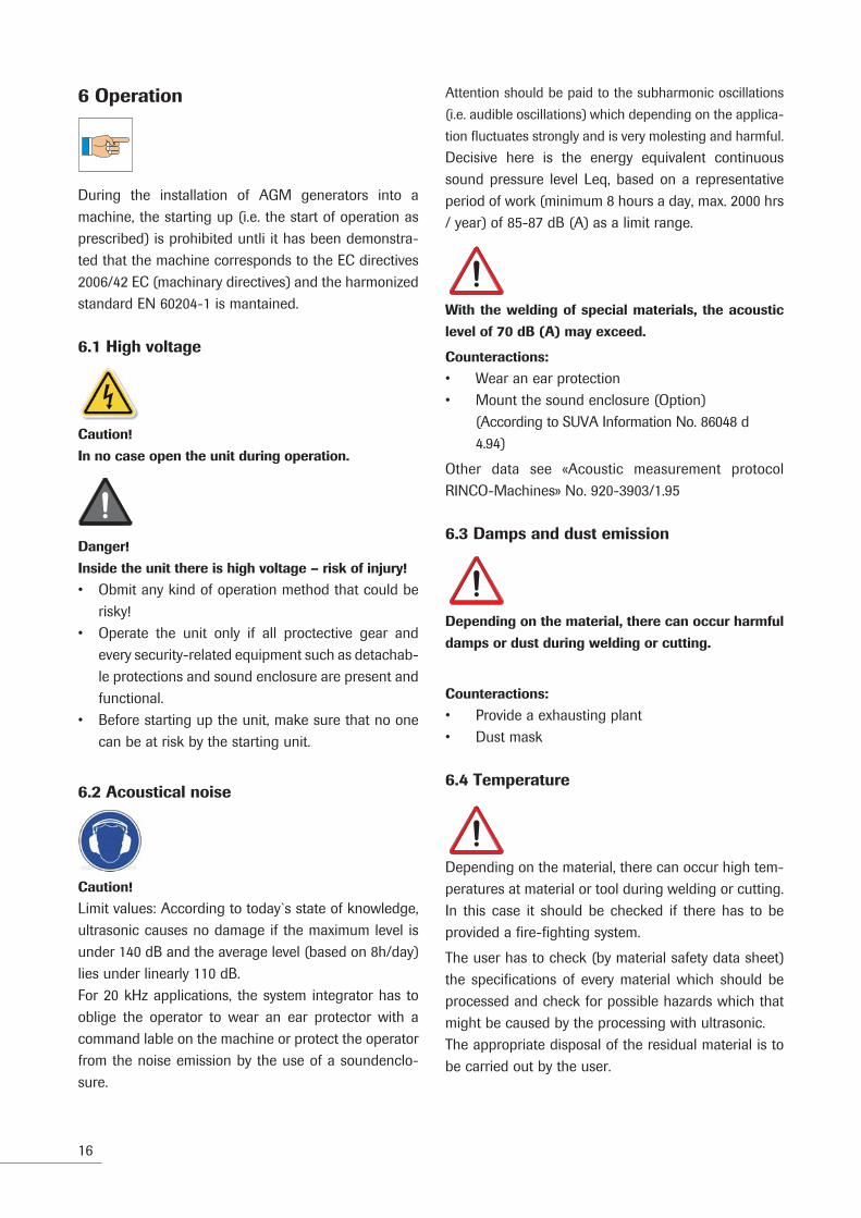
6 Operation
During the installation of AGM generators into a machine, the starting up (i.e. the start of operation as prescribed) is prohibited untli it has been demonstra-ted that the machine corresponds to the EC directives 2006/42 EC (machinary directives) and the harmonized standard EN 60204-1 is mantained.
6.1 High voltage
Caution!
In no case open the unit during operation.
Danger!
Inside the unit there is high voltage – risk of injury!
• Obmit any kind of operation method that could be risky!
• Operate the unit only if all proctective gear and every security-related equipment such as detachab-le protections and sound enclosure are present and functional.
• Before starting up the unit, make sure that no one can be at risk by the starting unit.
6.2 Acoustical noise
Caution!
Limit values: According to today`s state of knowledge, ultrasonic causes no damage if the maximum level is under 140 dB and the average level (based on 8h/day) lies under linearly 110 dB.For 20 kHz applications, the system integrator has to oblige the operator to wear an ear protector with a command lable on the machine or protect the operator from the noise emission by the use of a soundenclo-sure.
Attention should be paid to the subharmonic oscillations
(i.e. audible oscillations) which depending on the applica-
tion fluctuates strongly and is very molesting and harmful. Decisive here is the energy equivalent continuous sound pressure level Leq, based on a representative period of work (minimum 8 hours a day, max. 2000 hrs / year) of 85-87 dB (A) as a limit range.
With the welding of special materials, the acoustic
level of 70 dB (A) may exceed.
Counteractions:
• Wear an ear protection• Mount the sound enclosure (Option) (According to SUVA Information No. 86048 d 4.94)
Other data see «Acoustic measurement protocol RINCO-Machines» No. 920-3903/1.95
6.3 Damps and dust emission
Depending on the material, there can occur harmful
damps or dust during welding or cutting.
Counteractions:
• Provide a exhausting plant• Dust mask
6.4 Temperature
Depending on the material, there can occur high tem-peratures at material or tool during welding or cutting.In this case it should be checked if there has to be provided a fire-fighting system.
The user has to check (by material safety data sheet) the specifications of every material which should be processed and check for possible hazards which that might be caused by the processing with ultrasonic.The appropriate disposal of the residual material is to be carried out by the user.

17
6.5 Guarantee
RINCO ULTRASONICS delivers the system with a guarantee that corresponds to VSM (Swiss Association of Machinery Manufacturers).
The conditions for RINCO ULTRASONICS fulfilling its guarantee are, among other things, the following:
• The user possesses knowledge of the contents of this operating manual
• The instructions and warnings in this operating manual are followed
• The operating company is not permitted to under-taken any changes or conversions of the indivi dual parts of the press, the oscillator system or the generator of its own accord
RINCO ULTRASONICS is happy to explain any possible ambiguities or to provide instructions by our qualified staff via telephone.

18
7 Product information
7.1 Example of how to control the AGM gene-rator module with accessories
HF

19
7.2 Short overview of functional character-istics
Structured control concept for special machines
– All control tasks and parameter input must be done by a control system (PLC)
– Integrated 24 V power supply
– Digital inputs and outputs for control system
– Analog amplitude selection (40-100%)
– Analog power output (0-120%)
– Digital error coding (generator fault, oscillating system fault, limit fault)
Increased process reliability through active process
monitoring
– Digital control and regulation technology designed according to latest knowledge in the field of ultra- sonic welding
– Welding controlled by digital signal processor (DSP)
– Digital PLL for frequency tuning
– Welding modes:• time mode (accuracy 1 ms) with energy limits• energy mode (accuracy 0.1Ws) with time limits• continuous mode with power limits (accuracy 1W)
– Amplitude regulation
– Power measurement with accuracy of ± 1% of gen- erator performance
– Greater in-depth view of electrical signals of the enerator for system analysis and therefore recognition of limit conditions of generator and converter
Comprehensive protection of generator
– Automatic switch off in case of errors or if limits are reached
– Soft start and soft stop time can be set for protection of the oscillator system
Data transfer through bus-capable interfaces
– Bus-capable serial interface RS485– CANopen interface– Operating parameters can be set via interfaces

20
8 Available generator modules and their variants
8.1 Output power classes
AGM generators are high-power units and can beadapted to the relevant application.
The following output power classes are available:
20 kHz: 3000 W 2000 W 1500 W 1000 W
20-(4) kHz: 3000 W 2000 W 1500 W 1000 W
30 kHz: 1000 W 500 W
35 kHz: 900 W 600 W 400 W
35-(4) kHz: 900 W 600 W
40 kHz: 800 W 400 W
50 kHz: 100 W
70kHz: 100 W
Mains voltage:
20 kHz: 230 V +/-10% 50/60 Hz
30 kHz: 230 V +/-10% 50/60 Hz
35 kHz: 230 V +/-10% 50/60 Hz
40 kHz: 230 V +/-10% 50/60 Hz
50 kHz: 230 V +/-10% 50/60 Hz
70 kHz: 230 V +/-10% 50/60 Hz
For high-load applications, the internal cooling must be adapted to the environmental circumstances.
RINCO ULTRASONICS will be pleased to advise you in selecting a suitable design.
8.2 Suitable oscillator units
The oscillator units and generator modules should only be purchased from RINCO ULTRASONICS.For more information, please contact your RINCO ULTRASONICS service point.

21
3 (N)
2 (PE)
1 (L)
9 Operating and display elements
9.1 Connection of AGM generator
The AGM generator has a connection to the mains voltage, connections for the control system via digital inputs and outputs, via the CANopen interface and the RS485 interface and the connection for the oscillator system.
1 Mains voltage connection (STO_0)2 Interface (STO_1)3 Signals (STO_2)4 HF connection (STO_4)5 Fuse 24VDC power supply (F2)6 DIP switch (SW2)
9.2 DIP switch for CAN Terminators
ON terminators are switched on
Both CAN lines are linked to terminators. These are switched in when the two DIP switches are set to «on».
9.3 Mains voltage connection of generator module (STO_0)
Mains voltage to the generator is via the STO_0 connector. The necessary fusing and filtering on the power supply side must be implemented outside the AGM generator.
9.3.1 Connection
PIN allocation STO_0
PIN 1 Phase (L)PIN 2 Earth (PE)PIN 3 Neutral (N)
PIN allocation STO_0
4
1
2
6
3
5

22
9.4 24 V power supply, CANopen interface and RS485 interface (STO_1)
The serial RS485 interface, the CANopen bus system and the integrated 24V power supply 24VDC_OUT can be accessed via this connector.
PIN 1 RS485_Y PIN 6 CAN_HPIN 2 RS485_Z PIN 7 CAN_LPIN 3 RS485_A PIN 8 24VDC_OUTPIN 4 RS485_B PIN 9 GND24VDC_OUTPIN 5 GND_RS485 PIN 10 GND_CAN
9.4.1 24 V power supply
A 24 V power supply is integrated in the AGM generator.The power supply can be used, for example, for the triggering of the digital inputs and outputs. The output voltage of the 24V power supply is fused via fuse F2 and is on the front of the housing of the AGM gene-rator.
Output voltage Fuse F2
24VDC_OUT 1.25 A
9.4.2 RS485 protocol
The protocol of the RS485 interface is RINCO-specific. A detailed description of controlling via the RS485 interface can be requested from RINCOULTRASONICS.
9.4.3 CANopen protocol
A detailed description of controlling via the CANopen interface can be requested from RINCO ULTRASONICS.
low high
1
2
3
4
5
6
7
8
9
10
23
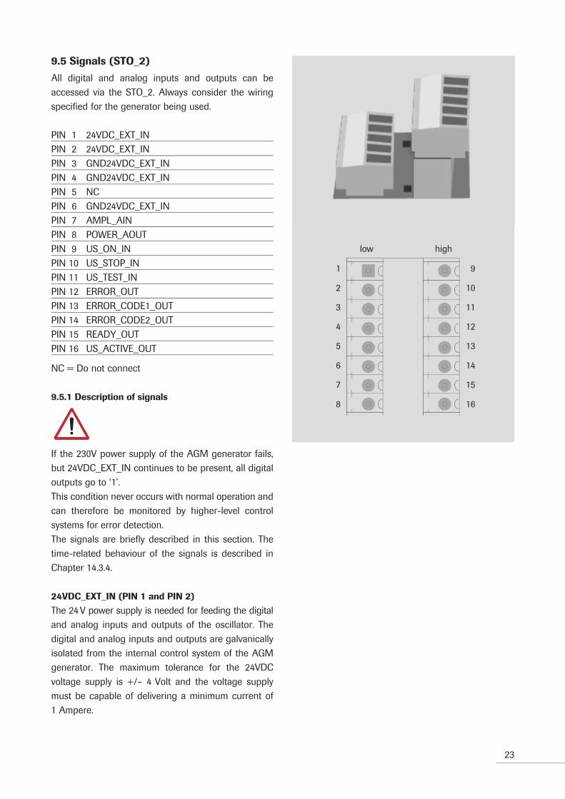
9.5 Signals (STO_2)
All digital and analog inputs and outputs can be accessed via the STO_2. Always consider the wiring specified for the generator being used.
PIN 1 24VDC_EXT_INPIN 2 24VDC_EXT_IN PIN 3 GND24VDC_EXT_INPIN 4 GND24VDC_EXT_INPIN 5 NCPIN 6 GND24VDC_EXT_IN PIN 7 AMPL_AIN PIN 8 POWER_AOUTPIN 9 US_ON_INPIN 10 US_STOP_INPIN 11 US_TEST_INPIN 12 ERROR_OUTPIN 13 ERROR_CODE1_OUTPIN 14 ERROR_CODE2_OUTPIN 15 READY_OUTPIN 16 US_ACTIVE_OUT
NC = Do not connect
9.5.1 Description of signals
If the 230V power supply of the AGM generator fails, but 24VDC_EXT_IN continues to be present, all digital outputs go to ‘1’.This condition never occurs with normal operation and can therefore be monitored by higher-level control systems for error detection. The signals are briefly described in this section. The time-related behaviour of the signals is described in Chapter 14.3.4.
24VDC_EXT_IN (PIN 1 and PIN 2)
The 24 V power supply is needed for feeding the digital and analog inputs and outputs of the oscillator. The digital and analog inputs and outputs are galvanically isolated from the internal control system of the AGM generator. The maximum tolerance for the 24VDC voltage supply is +/– 4 Volt and the voltage supply must be capable of delivering a minimum current of 1 Ampere.
low high
1
2
3
4
5
6
7
8
9
10
11
12
13
14
15
16

24
GND24VDC_EXT_IN (PIN 3, PIN 4 and PIN 6)
Ground reference of supply 24VDC_EXT_IN
AMPL_AIN (PIN 7)
The amplitude can be changed in real time during welding. The analog amplitude input must be activated once via the CANopen or RS485 interface. For more detailed information, please see Chapter 8.6.
Example AMPL_AIN
Voltage at AMPL_AIN in V Amplitude in %
4.0 4010.0 100
POWER_AOUT (PIN 8)
This analog output gives a linear voltage from 0 to 10VDC in proportion to the current output power. The maximum output voltage of 10VDC is used for 120% of the nominal generator output.
Example POWER_AOUT
Generator Current output power in W Current outptut power in % Voltage at
POWER_AOUT in V
AGM20-3000 2400 80 6.67AGM30-1000 1000 100 8.33AGM35-900 360 40 3.33AGM40-800 400 50 4.17AGM70-100 30 30 2.50
US_ON_IN (PIN 9)
Welding can be activated with this input. The input is high-active i.e. if 24VDC is available at this input, the welding process is started.
US_STOP_IN (PIN 10)
Welding can be stopped with input US_STOP_IN. If the input is set to 24VDC when welding is active, welding cea-ses immediately.
US_TEST_IN (PIN 11)
An ultrasonic test can be carried out with input US_TEST_IN. If the input is set to 24VDC, the ultrasonic test is started. The ultrasonic test lasts 250ms and can be used for diag-nosis purposes.Error messages can be acknowledged with US_TEST. However, acknowledgement with US-Test is only possible if the fault is no longer active (e.g. in case of overtempe-rature). A generator fault (see Chapter 17.1) must be ack-nowledged with an ultrasonic test.
25
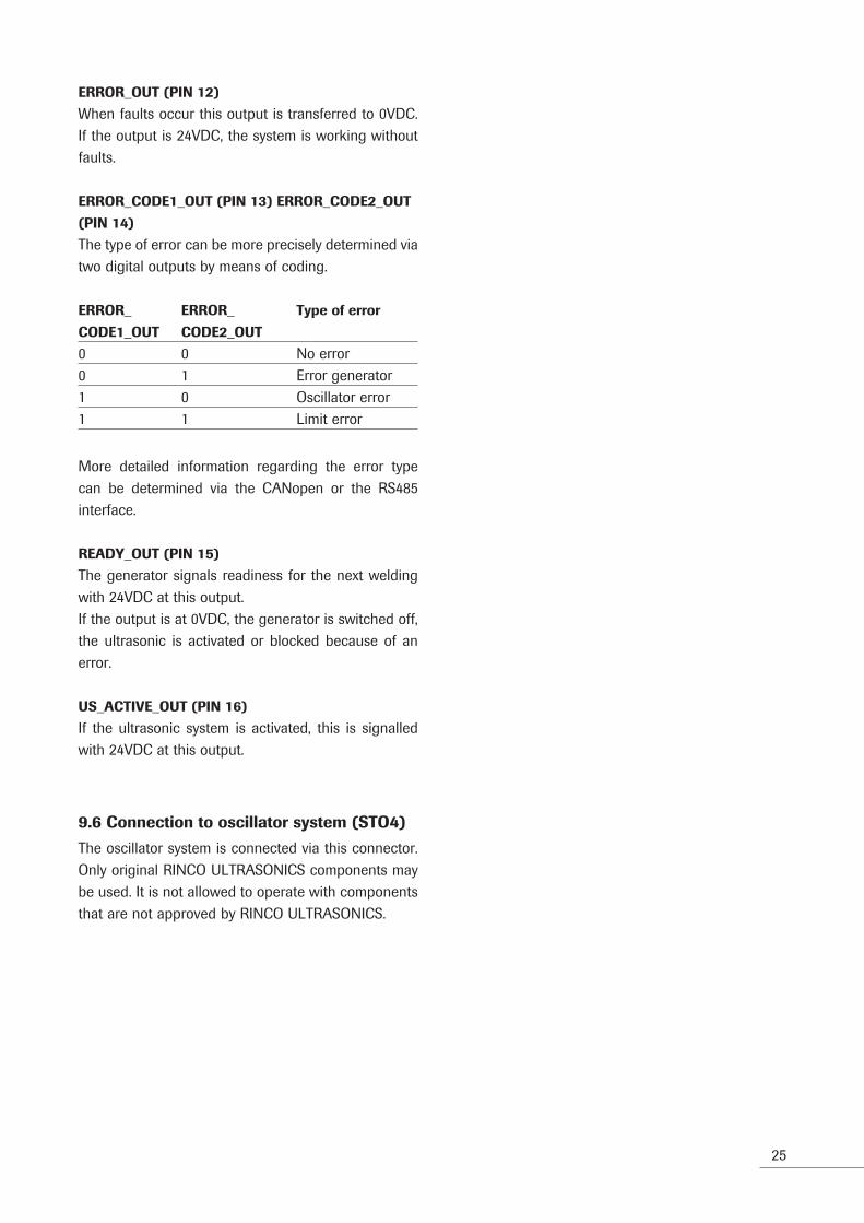
ERROR_OUT (PIN 12)
When faults occur this output is transferred to 0VDC. If the output is 24VDC, the system is working without faults.
ERROR_CODE1_OUT (PIN 13) ERROR_CODE2_OUT
(PIN 14)
The type of error can be more precisely determined via two digital outputs by means of coding.
ERROR_ ERROR_ Type of error
CODE1_OUT CODE2_OUT
0 0 No error0 1 Error generator1 0 Oscillator error1 1 Limit error
More detailed information regarding the error type can be determined via the CANopen or the RS485 interface.
READY_OUT (PIN 15)
The generator signals readiness for the next welding with 24VDC at this output.If the output is at 0VDC, the generator is switched off, the ultrasonic is activated or blocked because of an error.
US_ACTIVE_OUT (PIN 16)
If the ultrasonic system is activated, this is signalled with 24VDC at this output.
9.6 Connection to oscillator system (STO4)
The oscillator system is connected via this connector. Only original RINCO ULTRASONICS components may be used. It is not allowed to operate with components that are not approved by RINCO ULTRASONICS.

26
10 Operating modes
10.1 Welding modes
The AGM generator can be operated in three welding modes.
10.1.1 Time mode
In time mode, the user selects a target welding time (of up to 10 seconds). When starting the ultrasonic process, the welding time is reset and counted up in millisecond steps. When the target welding time is complete, the ultrasonic process is ended. The actual energy is measured during the ultrasonic process in time mode. If a maximum energy, which can be set, is exceeded, the ultrasonic process is interrupted with an error message.
10.1.2 Energy mode
A target energy level can be selected in energy mode. When the target energy level is reached, the ultrasonic process is ended. If a target maximum welding time (maximum 10 seconds) is exceeded before the target energy level is reached, the ultrasonic process is interrupted with an error message. After the end of the ultrasonic process the welding time is compared with a selectable minimum welding time. If the minimum welding time has not been reached, an error message is generated.
10.1.3 Continuous mode
A lower and upper output level can be set in 1W steps in continuous mode. If the output power exceeds these limits for longer than a selectable time, the ultrasonic process is interrupted with an error message. There is no time or energy monitoring.

27
10.2 Output and energy measurement
10.2.1 Output measurement and output curve
The output power is measured during the ultrasonic process and the power curve is stored in the AGM generator (in % of the nominal generator power).
The AGM automatically determines the time intervals (power measurement intervals) at which a measured value is stored. The output measurement intervals depend on the welding time.
Welding time Power measurement interval
in milliseconds
5 – 512 ms 1 513 – 1024 ms 21025 – 2048 ms 42049 – 4096 ms 84097 – 8192 ms 168193 – 16384 ms 32
The data memory can store 16,384 milliseconds.The power curve is only stored during a normal ultrasonic process. The power curve is not stored in the case of after-pulse and during power loss mea-surement.The power curve can be read out via the RS485 inter-face after the ultrasonic process. If the CANopen interface is used, the power can be read from the generator in real time.
10.2.2 Power overload
In order to prevent damage to the oscillator system and the generator, a protective mechanism is provided during operation with overload. If the gener ator is operated with more than a maximum of 120 % of the nominal generator power for more than 50 ms, the welding process is interrupted with an error message. The output power at which the system should be swit-ched off can be changed via the CANopen or RS485 interface.
10.2.3 Energy measurement
The energy value is updated every millisecond.
0
20
40
60
80
100
120
0 20 40 60 80 100 120
Time in ms
Po
wer
in %
-20
0
20
40
60
80
100
120
140
0 20 40 60 80 100 120 140
Time in ms
Po
wer
in %
50 ms
Example of a power curve
Power overload

Target amplitude
Start amplitude
Soft start time5–200 ms
Target welding time, target energy
Soft stop time0 – 50 ms
t
28
10.3 Soft start, Soft stop and Start amplitude
A soft start time and a soft stop time can be entered in order to protect the oscillator system. The soft start begins the ultrasonic process with a start amplitude and increases the amplitude linearly each millisecond to the target amplitude. The time from the start amplitude to the target amplitude is called the soft start time and can be selected between 5 ms and 200 ms. At the same time, frequency tuning is slowed down during the soft start. This means that start-up of sonotrodes where it is difficult to begin oscillation is made easier. With the soft stop, the ultrasonic process is not switched off immediately. The amplitude is dec-reased linearly from the current amplitude value down to 0. This time is called the soft stop time and can be selected between 0 ms and 50 ms. Frequency tuning is switched off during the soft stop.The illustration shows the ramp start value, the soft start time, soft stop time, set welding time and set energy.
Incorrect selection of the times must be prevented by the higher-level control system. If, for example, the target welding time is set to be shorter than the soft start time, the target amplitude is not achieved.
29
10.4 Ultrasonic test and power loss measu-rement
The power loss measurement can be used for fault diagnosis or when changing the oscillator system in order to find the optimum starting frequency for an ultrasonic process. It can be started via the CANopen or RS485 interface or via the digital US_TEST_IN input.
The power loss is measured at the amplitude which is currently set. The power loss measurement starts with the current frequency and lasts for 250 ms.The soft start and soft stop are used in the power loss measurement. The power curve is not stored.
10.5 Permitted frequency range
The maximum frequency range (permitted range of the ultrasonic oscillator) reaches from +500 Hz to –500 Hz to the nominal frequency (AGM70: +3000 Hz —-3000 Hz). The frequency range can be changed via the CANopen and RS485 interfaces. If the permitted frequency range is exceeded, the ultra- sonic process is interrupted with an error message.
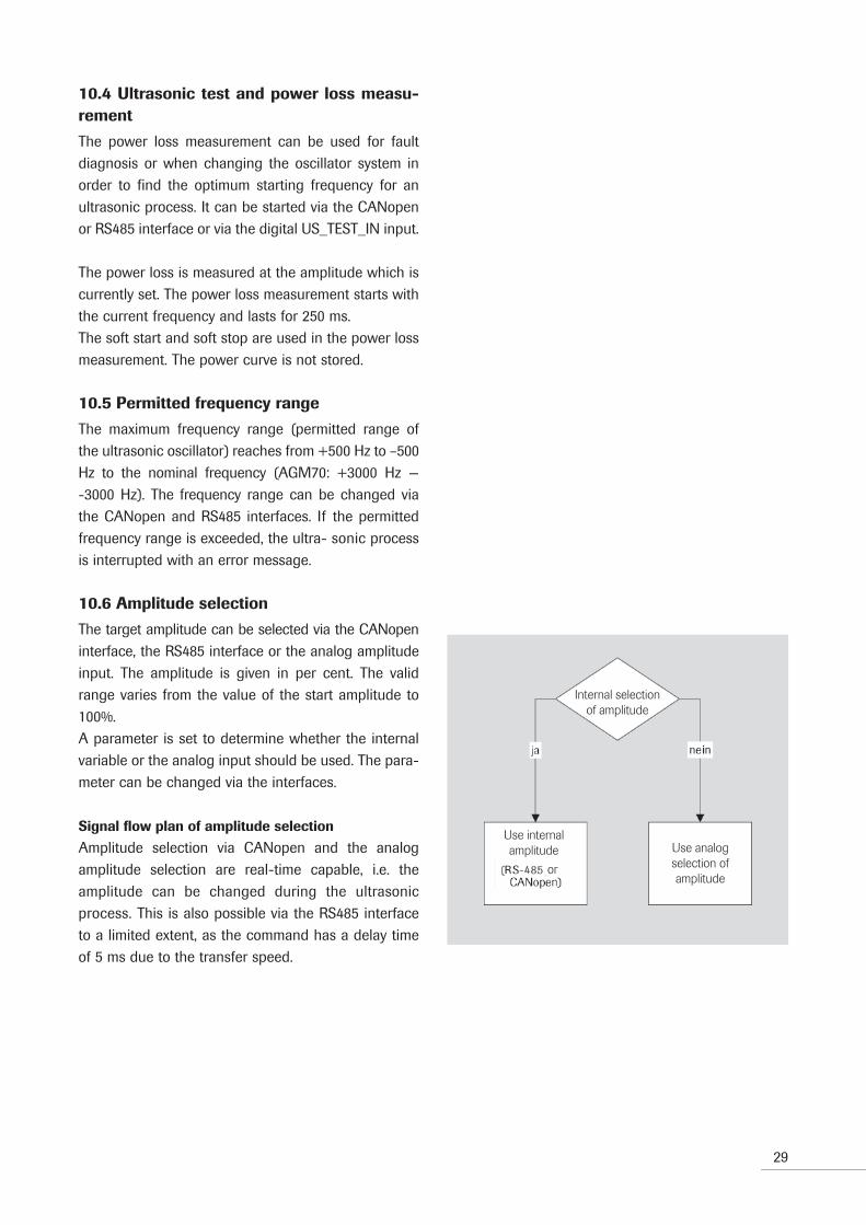
10.6 Amplitude selection
The target amplitude can be selected via the CANopen interface, the RS485 interface or the analog amplitude input. The amplitude is given in per cent. The valid range varies from the value of the start amplitude to 100%.A parameter is set to determine whether the internal variable or the analog input should be used. The para-meter can be changed via the interfaces.
Signal flow plan of amplitude selection
Amplitude selection via CANopen and the analog amplitude selection are real-time capable, i.e. the amplitude can be changed during the ultrasonic process. This is also possible via the RS485 interface to a limited extent, as the command has a delay time of 5 ms due to the transfer speed.
Internal selection of amplitude
Use internalamplitude
or
Use analogselection ofamplitude

30
11 Amplitude values
11.1 Amplitude values, 20 kHz generators
The different generator outputs result in different amplitudes. The amplitude values shown in the table below relate to the corresponding generator/booster/ sonotrode configuration. Therefore the effective welding amplitude can be read off directly.
9 Sonotrode24 Converter25 BoosterA AmplitudeK1 Coupling pointK2 Coupling point
11.1.2 Amplitude diagram of 20 kHz generators
HornAmplifi cation
Booster
A
24
K1
25
K2
9
31
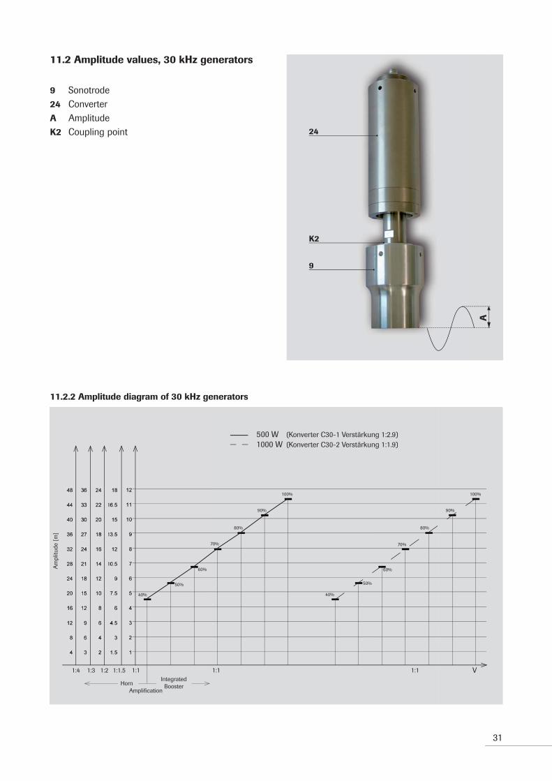
11.2 Amplitude values, 30 kHz generators
9 Sonotrode24 ConverterA AmplitudeK2 Coupling point
11.2.2 Amplitude diagram of 30 kHz generators
500 W (Converter C30-1 amplifi cation 1:2.9)1000 W (Converter C30-2 amplifi cation 1:1.9)
Am
plitu
de [
m]
HornIntegrated
BoosterAmplifi ction
500 W (Konverter C30-1 Verstärkung 1:2.9)1000 W (Konverter C30-2 Verstärkung 1:1.9)
100%100%
40%
50%
60%
70%
80%
90%
40%
90%
80%
70%
60%
50%
1:1 1:1
Am
plitu
de [
m]
1:1 V1:1.51:21:31:4
24
K2
9
A
HornAmplifi cation
IntegratedBooster
32
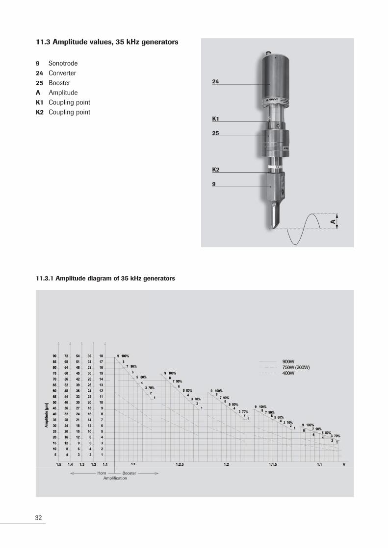
11.3 Amplitude values, 35 kHz generators
9 Sonotrode24 Converter25 BoosterA AmplitudeK1 Coupling pointK2 Coupling point
11.3.1 Amplitude diagram of 35 kHz generators
A
24
K1
25
K2
9
HornAmplifi cation
Booster

11.4 Amplitude values, 40 kHz generators
9 Sonotrode24 ConverterA AmplitudeK2 Coupling point
11.4.2 Amplitude diagram of 40 kHz generators
33
HornAmplifi cation
Am
plitu
de [
m]
800 W (Converter C40-2)400 W (Converter C40-2)
100%
100%
90%
90%
80%
70%
80%70%
60%
60%
50%
40%
40%
50%
1:1 1:1
Am
plitu
de [
m]
V1:1.51:21:31:4
24
K2
9
A
IntegratedBooster
HornAmplifi cation

34
HornAmplifi cation
HornAmplifi cation
11.5 Amplitude values, 70 kHz generators
9 Sonotrode24 ConverterA AmplitudeK2 Coupling point
11.5.1 Amplitude diagram of 70 kHz generators
24
K29
2
4
6
8
3
6
9
12
4
8
12
16
5
10
15
20
V1:11:21:31:41:5
Ampl
itude
[µm
]
1
2
3
4
9
18
27
36
8
16
24
32
7
14
21
28
6
12
18
24
10
20
30
40
1:101:91:81:71:6
1
9 100%7 90%
5 80%3 70%
86
42
A

Parameter Description Unit Min Max Standard
Welding mode 0 = time mode, 1 = energy mode, – 0 2 2 2 = continuous
Amplitude value Set amplitude % 40 100 60
Welding time in ms 5 9999 1000time mode
Energy minimum in Ws 0 Nominal output power Nominal output power/time mode * 10.0 1000
Energy maximum in Ws Nominal output power/ Nominal output power Nominal output powertime mode 1000 * 10.0 * 10.0
Set energy in Ws Nominal output power/ Nominal output power Nominal output powerenergy mode 1000 * 10.0 * 1.0
Minimum welding ms 0 9999 100time inenergy mode
Maximum welding ms 5 9999 1000time inenergy mode
Minimum output W 0 Nominal output power 0power in continuous * 1.2mode
Maximum output W 0 Nominal output power Nominal output powerpower in continuous * 1.2 * 1.1mode
Time to interrupt at ms 0 9999 100power overload incontinuous mode
After-pulse time ms 5 1000 100
Soft start time see Chapter 8.3, soft start ms 5 200 50
Soft stop time see Chapter 8.3, soft stop ms 0 50 0
Frequency reset Return frequency back to 0 = deactivated 1 = activated 0 = deactivated nominalfrequency after welding
Start amplitude s. Chapter. 8.3, Start amplitude % 10 40 30
Power measurement Measuring interval for power ms 1 32 Automatically set byinterval curve 1 ms, 2 ms, 4 ms, AGM generator 8 ms, 16 ms oder 32 ms (see section 5.4.1)
Power overload level The ultrasonic is interrupted W 5 Nominal output *1.2 Nominal output *1.1 in case of power overload
Upper frequency As positive offset to the Hz 50 500 500limit nominal frequency 3000 for AGM 70 3000 for AGM 70
Lower frequency As negative offset to the Hz 50 500 500limit nominal frequency 3000 for AGM 70 3000 for AGM 70
Amplitude source internal or external 0 = internal 1 = external 0 = internal
Cable length m 1 15 3
Slow control rate - 1 20 1
Fan mode 0 = Auto mode - 0 = Auto mode 1 = continous 1 = continous (>50 °C = ON) 1 = continous
35
12 Operating parameters
The AGM oscillator contains various parameters which are needed for the correct running of the ultrasonic pro-cess. These can be changed via the CANopen or RS485 interface.

36
13 Example applications
Some example applications are shown in the following text. If there are any questions, please contact RINCO ULTRASONICS.
The example applications show that the AGM
generator has to be protected in front of the main
voltage filter.
The digital inputs and outputs are supplied via an
external 24VDC supply in the example applications.
The integrated 24V power supply can be used as an
alternative (see Chapter 9.4.1).
13.1 Start and Stop Ultrasonic
Basic circuit to start the ultrasonic via digital input US_ON_IN. In order to start, the signal is set to 24VDC and back to 0VDC in order to switch off. As a further option, input US_STOP_IN is used to switch off the ultrasonic. The ultrasonic is switched off automatically in case of errors. In addition, the readiness message (Signal READY_OUT) and monitoring of the ultrasonic (Signal US_ACTIVE_OUT) is described.

37
1 The end of welding is triggered by one of the follo-wing conditions: – Input US_ON_IN set to 0VDC (continuous mode)– Parametered target value reached (time mode,
energy mode)– Stop via RS485 or CANopen
2 Welding was stopped because of an error:– Oscillator or limit error (READY_OUT changes
back to 24VDC)– Generator fault (READY_OUT remains at 0VDC)
3 Interruption of welding by 24VDC at US_STOP_IN
A Time delay until READY_OUT changes to 24VDC is <1 ms
B US_STOP_IN must be available for 5 ms until Stop is recognized
C Signal level US_ON_IN is not relevant
US_ON_IN
US_STOP_IN
E RROR_OUT
RE ADY_OUT
US_ACT IVE _OUT
A A A
B
C
Start1
Stop2
StopStart3
StopStart

38
13.2 Amplitude selection
The amplitude can be varied between the start ampli-tude and 100% via analog input AMPL_AIN (0 to 10V).If the analog signal is below the value for the start amplitude, the generator reports an error. It is possible to change the amplitude at all times.
The generator must be parametered for external
amplitude.
Please see Chapter 10.6 and 14.3.3 for more detailed information.

39
A Welding is carried out with 80% amplitude (80% corresponds to 8VDC)
B Welding is started with 100% amplitude (10VDC) and will be reduced constantly and linearly to 40% amplitude (4VDC).
C Welding is started with 100% amplitude (10VDC). After the desired time the amplitude is reduced externally. The welding is interrupted because of an error.
1 The end of welding was triggered by one of the following conditions: – Input US_ON_IN set to 0VDC (continuous mode)– Parametered target value reached (time mode,
energy mode)– Stop via RS485 or CANopen
2 Welding was interrupted because of an error or fault: – Oscillator or limit error (READY_OUT changes
back to 24VDC)– Generator error (READY_OUT remains at 0VDC)
3 The end of welding was triggered by one of the following conditions: – Input US_ON_IN set to 0VDC– Parametered target value reached– Stop via RS485
4 Welding was interrupted because of an error:– Oscillator or limit error (READY_OUT changes
back to 24VDC)– Generator fault (READY_OUT remains at 0VDC)

40
13.3 Power measurement
The analog signal of the POWER_AOUT (0 to 10VDC) output can be used for any desired interpretations or control tasks. The maximum value of 10VDC corre-sponds to an output of 120% of the nominal output power.This means that 100% nominal output power is represented by a voltage value of 8.33VDC.The timing diagrams with POWER_AOUT were created with a theoretical model for welding, as all applic-ations differ hugely in practice. It is assumed that the characteristics of the workpiece to be processed and the pressure conditions at the tool do not change. The power output will demonstrate deviating behaviour in practice.

41
1,2
The end of welding was triggered by one of the following conditions: – Input US_ON_IN set to 0VDC (continuous mode)– parametered target value reached (time mode,
energy mode)– Stop via RS485 or CANopen
A Welding is started with 80% amplitude (8VDC) and is increased to 100% amplitude (10VDC) after half of the welding time. In the theoretical model the output power depends on the amplitude, it there-fore goes through a sudden increase after half the welding time. The output value (0 to 10VDC) varies depending on application.
B Welding is started by 24VDC at input US_ON_IN. During the welding process the analog output POWER_OUT (0 to 10VDC) is read into a control system and integrated up to an energy. When the set energy is reached, the signal US_ON_IN is set to 0VDC and welding stops. This method is desi-gnated as energy mode.
US_ON_IN
AMPL_AIN
POWER_AOUT
100%
40%
Start1
Stop Start Stop2
A B100%
0%
42
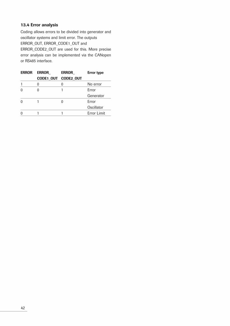
13.4 Error analysis
Coding allows errors to be divided into generator and oscillator systems and limit error. The outputsERROR_OUT, ERROR_CODE1_OUT andERROR_CODE2_OUT are used for this. More precise error analysis can be implemented via the CANopen or RS485 interface.
ERROR ERROR_ ERROR_ Error type
CODE1_OUT CODE2_OUT
1 0 0 No error0 0 1 Error Generator0 1 0 Error Oscillator0 1 1 Error Limit

43
1,5
The end of welding was triggered by one of the following conditions: – Input US_ON_IN set to 0VDC (continuous mode)– Parametered target value reached (time mode,
energy mode)– Stop via RS485 or CANopen
2 End of welding by generator error.
3 End of welding by oscillator system error.
4 End of welding by limit error
A In the case of generator errors the signal READY_OUT remains at 0VDC. This signals that no new welding can be started.
B The generator error no longer exists and an ult-rasonics test was performed. The signal ERROR_CODE2_OUT changes to 24VDC. For this reason the signal READY_OUT also changes to 24VDC. The next welding process can be started.
C If an error exists (ERROR_OUT at 0VDC), a welding process can be started with 24VDC at US_ON_IN. The prerequisite is the readiness signal via 24VDC at output READY_OUT.
US_ON_IN
ERROR_OUT
ERROR_CODE1_OUT
ERROR_CODE2_OUT
READY_OUT
US_ACTIVE_OUT
Start1
Stop Start2
Stop Start3
Stop Start4
Stop Start5
Stop
A
B
C C C

44
14 Technical data
14.1 Power supply 230V
The AGM generator requires a supply voltage of 230VAC.The permissible voltage levels are:
Parameter Min Typical Max Unit
230VAC 200 230 250 V
14.2 Integrated 24VDC power supply
The AGM generator includes an unregulated 24V power supply. The output voltage of the power supply 24VDC_OUT can be accessed via connection STO_1 and is fused with fuse F2 (on the front of the AGM generator housing).
Parameter Typical Unit
24VDC_OUT 24 V
14.3 Analog and digital inputs and outputs 14.3.1 Voltage supply and voltage level
The digital and analog inputs and outputs are galva-nically isolated from the internal control system of the AGM generator. They therefore require an external power supply (24VDC_EXT_IN) of 24V.The voltage level of the power supply and the digital inputs and outputs are shown in the following table.
If the 230V power supply of the AGM fails but
24VDC_EXT_IN continues to be present, all digital
outputs go to ‘1’. This condition is never present in
normal operation and can therefore by monitored
by higher-level control systems for purposes of fault
detection.
Parameter Condition Min Type Max Unit
24VDC_EXT_IN 20 24 28 VDigital Input High Signal 20 VDigital Input Low Signal 1 VDigital Output High Signal VSupply = 24V 24 VDigital Output Low Signal VSupply = 24V 0 0.5 V

45
14.3.2 Overview of inputs and outputs
The following table shows an overview of inputs andoutputs.
Name Type Description Voltage level
US_ON_IN Input Starts ultrasonic process 24VDC = Activate ultrasonic process Input current = 5 mA typical Input resistance = 4.7 kUS_STOP_IN Input Stops ultrasonic process 24VDC = Stop Input current = 5 mA typical Input resistance = 4.7 kUS_TEST_IN Input Acknowledges errors and 24VDC = Test carries out a power loss Input current = 5 mA typical measurement Input resistance = 4.7 kAMPL_AIN Input Analog Amplitude selection 0–10 V corresponds to an amplitude between 0% and 100% Accuracy = ± 3% Input current = 0.3 mA typical Input resistance = 33 kUS_ACTIVE_OUT Output Ultrasonic process active 24VDC = Ultrasonics active Output current = 100 mA max.US_ERROR_OUT Output Generator error 0VDC = Error, 24VDC no error Output current = 100 mA max.US_ERROR_CODE1_OUT Outputs Coding Generator error 24VDC = 1, 0VDC = 0US_ERROR_CODE2_OUT Output current = 100 mA max. 01 -> Generator error 10 -> Oscillator system error 11-> Limit errorUS_READY_OUT Output Generator is ready for the 24VDC = Ready next ultrasonic process Output current 100 mA max.POWER_AOUT Output Analog power output 0-10V corresponds to 0W up to generator output * 1.2 (e.g. 0 to 3600 W at 3000 W generator Accuracy = ± 3% Output current = 10 mA max. (see 12.3.3) Output resistance = 680

46
14.3.3 Analog input and output
Because of the circuit the analog input has a delay of max. 0.7 ms. The analog power output also has a delay of 0.7 ms. In order to avoid inaccuracy at the analog input the internal resistance of the connected source may not be greater than 330 .
In order to avoid inaccuracy at the power output, the internal resistance of the connected drain must be greater than 68 k.
POWER_AOUT-Output
AMPL_AIN-Input
AGM
AGM
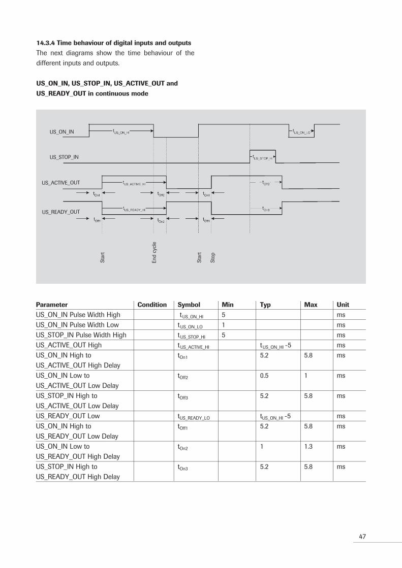
14.3.4 Time behaviour of digital inputs and outputs
The next diagrams show the time behaviour of the different inputs and outputs.
US_ON_IN, US_STOP_IN, US_ACTIVE_OUT and
US_READY_OUT in continuous mode
47
Parameter Condition Symbol Min Typ Max Unit
US_ON_IN Pulse Width High tUS_ON_HI 5 msUS_ON_IN Pulse Width Low tUS_ON_LO 1 msUS_STOP_IN Pulse Width High tUS_STOP_HI 5 msUS_ACTIVE_OUT High tUS_ACTIVE_HI tUS_ON_HI -5 msUS_ON_IN High to tOn1 5.2 5.8 msUS_ACTIVE_OUT High DelayUS_ON_IN Low to tOff2 0.5 1 msUS_ACTIVE_OUT Low DelayUS_STOP_IN High to tOff3 5.2 5.8 msUS_ACTIVE_OUT Low DelayUS_READY_OUT Low tUS_READY_LO tUS_ON_HI -5 msUS_ON_IN High to tOff1 5.2 5.8 msUS_READY_OUT Low DelayUS_ON_IN Low to tOn2 1 1.3 msUS_READY_OUT High DelayUS_STOP_IN High to tOn3 5.2 5.8 msUS_READY_OUT High Delay
Star
t
End
cycl
e
Star
t
Stop
US_ON_IN
US_STOP_IN
US_ACTIVE_OUT
US_READY_OUT

48
Parameter Condition Symbol Min Typ Max Unit
US_ON_IN Pulse Width High tUS_ON_HI 5 msUS_STOP_IN Pulse Width High tUS_STOP_HI 5 msUS_ACTIVE_OUT High time mode, tUS_ACTIVE_HI 249.7 250.2 250.7 ms nominal US-Time = 250 msUS_ACTIVE_OUT High time mode, tUS_ACTIVE_HI 999.7 1000.2 1000.7 ms nominal US-Time = 1000 msUS_ON_IN High to tOn1 5.2 5.8 msUS_ACTIVE_OUT High DelayUS_STOP_IN High to tOff2 5.2 5.8 msUS_ACTIVE_OUT Low DelayUS_READY_OUT Low time mode, tUS_READY_LO 249.7 250.2 250.7 ms nominal US-Time = 250 msUS_READY_OUT Low time mode, tUS_READY_LO 999.7 1000.2 1000.7 ms nominal US-Time = 1000 msUS_STOP_IN High to tOff1 5.2 5.8 msUS_READY_OUT Low DelayUS_ON_IN High to tOn2 5.2 5.8 msUS_READY_OUT High Delay
US_ON_IN, US_STOP_IN, US_ACTIVE_OUT and
US_READY_OUT in time and energy mode
49
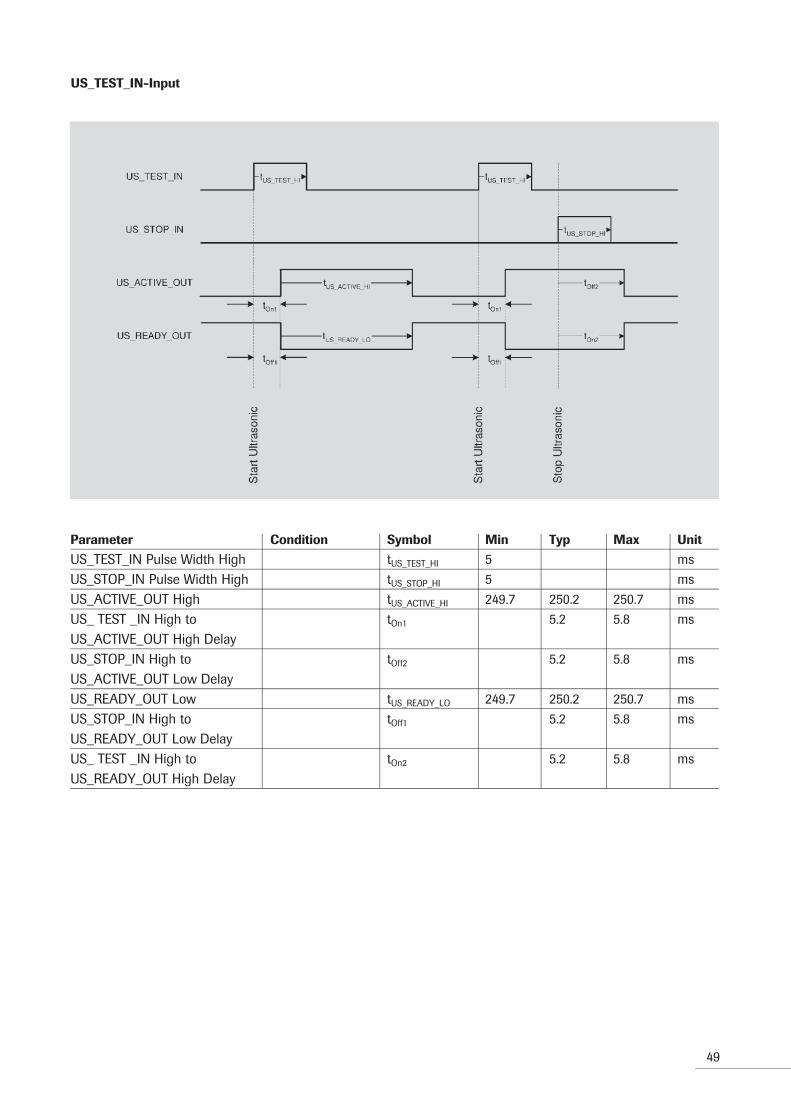
US_TEST_IN-Input
Parameter Condition Symbol Min Typ Max Unit
US_TEST_IN Pulse Width High tUS_TEST_HI 5 msUS_STOP_IN Pulse Width High tUS_STOP_HI 5 msUS_ACTIVE_OUT High tUS_ACTIVE_HI 249.7 250.2 250.7 msUS_ TEST _IN High to tOn1 5.2 5.8 msUS_ACTIVE_OUT High Delay US_STOP_IN High to tOff2 5.2 5.8 msUS_ACTIVE_OUT Low DelayUS_READY_OUT Low tUS_READY_LO 249.7 250.2 250.7 msUS_STOP_IN High to tOff1 5.2 5.8 msUS_READY_OUT Low DelayUS_ TEST _IN High to tOn2 5.2 5.8 msUS_READY_OUT High Delay

50
Parameter Condition Symbol Min Typ Max Unit
Error to US_ACTIVE_OUT Low tOff1 0.2 0.5 msDelayError to ERROR_OUT Low Delay tOff2 0.2 0.5 msError to ERROR_CODE1_OUT High tOn1 0.2 0.5 msDelayError to ERROR_CODE2_OUT High tOn2 0.2 0.5 msDelayUS_ON_IN High to ERROR_OUT tOn3 5.2 5.8 msHigh DelayUS_ON_IN High to tOff3 5.2 5.8 msERROR_CODE1_OUT Low DelayUS_ON_IN High to tOff4 5.2 5.8 msERROR_CODE2_OUT Low Delay
Error outputs
Star
t
Lim
it Er
ror
Star
t
Con
vert
er E
rror
Star
t with
out
Erro
r

51
15 Cleaning and maintenance
The generator does not require any maintenance.However, the converter, booster and sonotrode should be checked from time to time and kept clean from the outside.
16 Services internal components
This generator is maintenance-free if correctly ope-rated. If fan cooling is intended, it must be periodically checked for dust depending on operating environment and cleaned if necessary.If filters are used in combination with a fan, these must be replaced periodically.
17 Disposal
The generator module has to be disposed properly. Please contact RINCO ULTRASONICS AG.

52
18 Error elimination
In the case of errors which do not originate from the application, the nearest RINCO ULTRASONICS service point must be contacted.
18.1 General faults
Fault Corrective action
Power (yellow LED) - Check mains voltage supplynot illuminated - Check fuse F1
Control via digital I/O`s - Check fuse F2 (1.25A)not possible - Check power supply 24V_EXT_IN (PIN1, 2) GND is Pin 3, 4
Noise - Check support - Check breakaway torques of the oscillator system (between converter, booster and horn) - Check power dissipation of the oscillator system in non-clamped and clamped condition, if necessary replace converter, booster or horn
Heat - Converter- and horn cooling is application dependent - Unusual heat development can be caused by loose components or cracks in the oscillator system
53
19 Error messages
The following tables show the error messages of the AGM generator. The error messages can be selected through the interfaces RS485 ore CANopen, therefore RINCO ULTRASONICS offers the software GenParam.
The error messages are devided into three ERROR CODE groups (see chapter 9.5.1, P. 25):
• Generator fault - Code 0_1
• Converter- and - Code 1_0application fault
• Limit fault - Code 1_1
Error messages can be acknowledged with US_TEST. The acknowledgement with the US-TEST can be carri-ed out through CANopen or RS485 as well as through the US_TEST_IN-input. A confirmation with US-TEST is only possible, if the error is no longer active, e.g. no longer an overtemperature exists.
All generator faults have absolutely to be acknowled-ged with US_TEST. Converter- and application faults as well as limit faults can be cleared with a new star-ting signal. That means, at these types of errors the generator can start a new cycle without confirming the error message before.

54
19.1 Generator faults (Code 0_1)
Fault Cause Reaction Corrective action
Mains voltage - The at the generator - Error message is - Check mains voltagetoo low adjacent mains voltage generated is below 85% of the - Ultrasonic process nominal voltage interrupted - New ultrasonic process is blocked - Error message must be acknowledged with US-Test.
Internal power - Internal power supply - Error message is generated - Conntact yoursupply defective failed by a short - Ultrasonic process service centre circuit, temperature excess interrupted or by defective parts - New ultrasonic process is blocked - Error message must be acknowledged with US-Test.
Minimal modulation - Minimal modulation of - Error message is generated - Increase amplitudeend stage end stage, defective - Ultrasonic process components in the generator interrupted - Very low amplitude - New ultrasonic process choice is blocked - Error message must be acknowledged with US-Test.
Generator - The internal temperature - Error message is generated - Check fans for functiontemperature monitoring of the generator - Ultrasonic process and soilingis too high reports a too high value interrupted - Turn on the fans using the - New ultrasonic process jumper at the inside of is blocked the housing - Error message must be (at SN < 2000) or acknowledged with US-Test. select via GenParam the option FAN on (SN > 2000) - Reduce the ambient- temperature - Reduce Duty Cycle

55
19.2 Converter and application faults (Code 1_0)
Fault Cause Reaction Corrective action
Frequency - Oscillator system not - Error message is - Check cable connectionminimum connected generated - Check cableexceeded - Oscillator system faulty - Ultrasonic process - Check/replace converter - Too high damping of the interrupted - Check assembling oscillator system through - New ultrasonic process oscillator system high pressure starts at nominal frequency, - Check temperature - Defect at the oscillator respectively at start frequency oscillator system system - Check/replace horn - Reduce welding pressure
Frequency - Oscillator system not - Error message is - Horn abrasionmaximum connected generated - Check cable connectionexceeded - Oscillator system faulty - Ultrasonic process - Check cable - Too high damping of the interrupted - Check/replace converter oscillator system through - New ultrasonic process - Check assembling high pressure starts at nominal frequency, oscillator system -Defect at the oscillator respectively at start frequency - Check temperature system oscillator system - Check/replace horn - Reduce welding pressure
Maximum - Oscillator system faulty - Error message is generated - Reduce start amplitudeconverter voltage - Too high damping of the - Ultrasonic process - Increase softstart timeexceeded oscillator system through interrupted - Check/replace converter, high pressure - New ultrasonic process horn, booster - Wrong parameterisation starts at nominal frequency, - Adapt start frequency respectively at start frequency
Pover overload - Oscillator system faulty - Error message is generated - Check parameter choicelevel exceeded - Too high damping of the - Ultrasonic process - Reduce pressure oscillator system through interrupted - Use a more powerful high pressure - New ultrasonic process starts generator at the last welding frequency
56
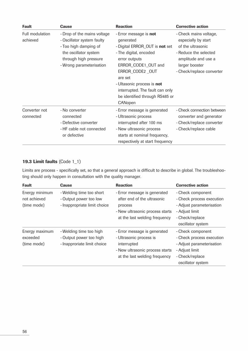
19.3 Limit faults (Code 1_1)
Limits are process - specifically set, so that a general approach is difficult to describe in global. The troubleshoo-ting should only happen in consultation with the quality manager.
Fault Cause Reaction Corrective action
Energy minimum - Welding time too short - Error message is generated - Check componentnot achieved - Output power too low after end of the ultrasonic - Check process execution(time mode) - Inappropriate limit choice process - Adjust parameterisation - New ultrasonic process starts - Adjust limit at the last welding frequency - Check/replace oscillator system
Energy maximum - Welding time too high - Error message is generated - Check componentexceeded - Output power too high - Ultrasonic process is - Check process execution(time mode) - Inapproriate limit choice interrupted - Adjust parameterisation - New ultrasonic process starts - Adjust limit at the last welding frequency - Check/replace oscillator system
Fault Cause Reaction Corrective action
Full modulation - Drop of the mains voltage - Error message is not - Check mains voltage,achieved - Oscillator system faulty generated especially by start - Too high damping of - Digital ERROR_OUT is not set of the ultrasonic the oscillator system - The digital, encoded - Reduce the selected through high pressure error outputs amplitude and use a - Wrong parameterisation ERROR_CODE1_OUT and larger booster ERROR_CODE2 _OUT - Check/replace converter are set - Ultasonic process is not interrupted. The fault can only be identified through RS485 or CANopen
Converter not - No converter - Error message is generated - Check connection betweenconnected connected - Ultrasonic process converter and generator - Defective converter interrupted after 100 ms - Check/replace converter - HF cable not connected - New ultrasonic process - Check/replace cable or defective starts at nominal frequency, respectively at start frequency

57
Fault Cause Reaction Corrective action
Minimum welding - Welding time too short - Error message is generated - Check componenttime not achieved - Output power too high after end of the ultrasonic - Check process execution(energy mode) - Inapproriate limit choice process - Adjust parameterisation - New ultrasonic process starts - Adjust limit at the last welding frequency - Check/replace oscillator system
Welding time - Welding time too high - Error message is generated - Check componentmaximum - Output power too high - Ultrasonic process - Check process executionexceeded - Inapproriate limit choice interrupted - Adjust parameterisation(energy mode) - New ultrasonic process starts - Adjust limit at the last welding frequency - Check/replace oscillator system
Minimum output - Output power too low - Error message is generated - At this type of errorpower not achieved - Inapproriate limit choice - Ultrasonic process it is imperativ to reassess(continuous mode) interrupted also the delay time - New ultrasonic process starts - Check component at the last welding frequency - Check process execution - Adjust parameterisation - Adjust limit - Check/replace oscillator system
Maximum output - Output power too high - Error message is generated - At this type of errorpower exceeded - Inapproriate limit choice - Ultrasonic process it is imperativ to reassess(continuous mode) interrupted also the delay time - New ultrasonic process starts - Check component at the last welding frequency - Check process execution - Adjust parameterisation - Adjust limit - Check/replace oscillator system
Analog amplitude - The voltage at the external - Error message is generated - Set correctly the voltagetoo low analog amplitude input is, - Ultrasonic process on the external before or during the interrupted analog amplitude input ultrasonic process, blow the - New ultrasonic process starts value of the start amplitude at the last welding frequency (less than 1V-4V). - Start of the ultrasonic This value is dependent process is denied on the parameterisation of the start amlitude, which can be 10 to 40%.

58
20 Service Addresses
If you experience problems with welding or technical faults with the equipment, please contact the Techni cal Customer Service of RINCO ULTRASONICS AG, who will be pleased to help you.For an efficient response our Customer Service requires the following information:
– A precise description of the technical fault or welding problem.
Our address:
RINCO ULTRASONICS AGIndustriestrasse 4CH-8590 RomanshornSwitzerland
National callsTel. 071 466 41 00Fax 071 466 41 01
International callsTel. ++41 71 466 41 00Fax ++41 71 466 41 [email protected]

59
Dat
e C
arrie
d ou
t wor
k Pe
rson
in c
harg
e N
ote

RINCO ULTRASONICS AG
Industriestrasse 4CH-8590 Romanshorn 1Switzerland
Tel. +41 71 466 41 00Fax +41 71 466 41 01
CR
ES
T G
RO
UP
CO
MP
AN
Y