generation iii coulter - yetter co · generation iii coulter 2995-012 – fertilizer coulter...
TRANSCRIPT

GENERATION III COULTER
MODEL 2995
SET-UP & PARTS MANUAL
2565-490_REV_D ● 07/13
YETTER MANUFACTURING CO. FOUNDED 1930
Colchester, IL 62326-0358 Toll free: 800/447-5777
309/776-3222 (Fax) Website: www.yetterco.com
E-mail: [email protected]
2
FOREWORD
You’ve just joined an exclusive but rapidly growing club. For our part, we want to welcome you to the group and thank you for buying a Yetter product. We hope your new Yetter products will help you achieve both goals-increase your productivity and increase your efficiency so that you may generate more profit. This operator’s manual has been designed into four major sections: Foreword, Safety Precautions, Installation Instructions and Parts
Breakdown.
This SAFETY ALERT SYMBOL indicates important safety messages in
the manual. When you see this symbol, be alert to the possibility of PERSONAL INJURY and carefully read the message that follows. The word NOTE is used to convey information that is out of context with the manual text. It contains special information such as specifications, techniques and reference information of a supplementary nature. The word IMPORTANT is used in the text when immediate damage will occur to the machine due to improper technique or operation. Important will
apply to the same information as specified by note only of an immediate and urgent nature. It is the responsibility of the user to read the operator’s manual and comply with the safe and correct operating procedure and to lubricate and maintain the product according to the maintenance schedule in the operator’s manual. The user is responsible for inspecting his machine and for having parts repaired or replaced when continued use of the product would cause damage or excessive wear to the other parts. It is the user’s responsibility to deliver his machine to the Yetter dealer who sold him the product for service or replacement of defective parts, which are covered by the warranty policy. If you are unable to understand or follow the instructions provided in this publication, consult your local Yetter dealer or contact:
YETTER MANUFACTURING CO. 309/776-4111 800/447-5777
309/776-3222 (FAX) Website: www.yetterco.com
E-mail: [email protected]
WARRANTY Yetter Manufacturing warrants all products manufactured and sold by it against defects in material. This warranty being expressly limited to replacement at the factory of such parts or products as shall appear to be defective after inspection. This warranty does not obligate the Company to bear cost of labor in replacement of parts. It is the policy of the Company to make improvements without incurring obligations to add them to any unit already sold. No warranty is made or authorized to be made, other than herein set forth. This warranty is in effect for one year after purchase.
Dealer ___________________________________________________ Yetter Manufacturing warrants its own products only and cannot be responsible for damages to equipment on which mounted.

3
SAFETY
A brief description of signal words that may be used in this manual: CAUTION: Used as a general reminder of good safety practices or to direct attention to unsafe practices. WARNING: Denotes a specific potential hazard. DANGER: Denotes the most serious specific potential hazard.
SAFETY PRECAUTIONS You can make your farm a safer place to live and work if you observe the safety precautions given. Study these precautions carefully and insist that they be followed by those working with you and for you. Finally, remember this: an accident is usually caused by someone’s carelessness, neglect, or oversight.
WARNING
Never clean, lubricate or adjust a machine that is in motion. Always lower or block the implement before performing service. If machine must be serviced in the raised position, jack or block it up to prevent it from accidentally falling and injuring someone. Do not allow riders on the tractor or implement. Use speeds and caution dictated by the terrain being traversed. Do not operate on any slope steep enough to cause tipping or loss of control. Be sure all personnel are clear of the immediate area before operating. Read and understand the operator’s manual and require all other persons who will operate the equipment to do the same. Be familiar with all tractor and implement controls and be prepared to stop engine and implements quickly in an emergency.
CAUTION Consult your implement and tractor operator’s manual for correct and safe operating practices. Beware of towed implement width and allow safe clearance.
FAILURE TO HEED MAY RESULT IN PERSONAL INJURY OR DEATH.
4
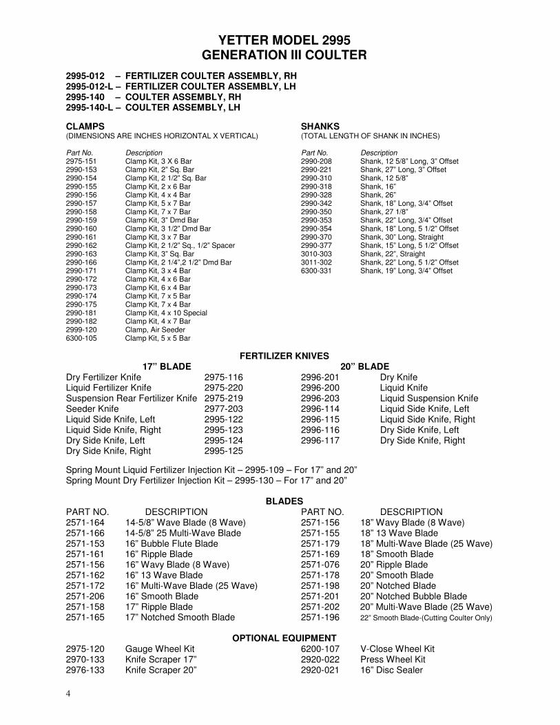
YETTER MODEL 2995 GENERATION III COULTER
2995-012 – FERTILIZER COULTER ASSEMBLY, RH 2995-012-L – FERTILIZER COULTER ASSEMBLY, LH 2995-140 – COULTER ASSEMBLY, RH 2995-140-L – COULTER ASSEMBLY, LH
CLAMPS (DIMENSIONS ARE INCHES HORIZONTAL X VERTICAL) Part No. Description 2975-151 Clamp Kit, 3 X 6 Bar 2990-153 Clamp Kit, 2” Sq. Bar 2990-154 Clamp Kit, 2 1/2” Sq. Bar 2990-155 Clamp Kit, 2 x 6 Bar 2990-156 Clamp Kit, 4 x 4 Bar 2990-157 Clamp Kit, 5 x 7 Bar 2990-158 Clamp Kit, 7 x 7 Bar 2990-159 Clamp Kit, 3” Dmd Bar 2990-160 Clamp Kit, 3 1/2” Dmd Bar 2990-161 Clamp Kit, 3 x 7 Bar 2990-162 Clamp Kit, 2 1/2” Sq., 1/2” Spacer 2990-163 Clamp Kit, 3” Sq. Bar 2990-166 Clamp Kit, 2 1/4”,2 1/2” Dmd Bar 2990-171 Clamp Kit, 3 x 4 Bar 2990-172 Clamp Kit, 4 x 6 Bar 2990-173 Clamp Kit, 6 x 4 Bar 2990-174 Clamp Kit, 7 x 5 Bar 2990-175 Clamp Kit, 7 x 4 Bar 2990-181 Clamp Kit, 4 x 10 Special 2990-182 Clamp Kit, 4 x 7 Bar 2999-120 Clamp, Air Seeder 6300-105 Clamp Kit, 5 x 5 Bar
SHANKS (TOTAL LENGTH OF SHANK IN INCHES)
Part No. Description 2990-208 Shank, 12 5/8” Long, 3” Offset 2990-221 Shank, 27” Long, 3” Offset 2990-310 Shank, 12 5/8” 2990-318 Shank, 16” 2990-328 Shank, 26” 2990-342 Shank, 18” Long, 3/4” Offset 2990-350 Shank, 27 1/8” 2990-353 Shank, 22” Long, 3/4” Offset 2990-354 Shank, 18” Long, 5 1/2” Offset 2990-370 Shank, 30” Long, Straight 2990-377 Shank, 15” Long, 5 1/2” Offset 3010-303 Shank, 22”, Straight 3011-302 Shank, 22” Long, 5 1/2” Offset 6300-331 Shank, 19” Long, 3/4” Offset
FERTILIZER KNIVES 17” BLADE
Dry Fertilizer Knife 2975-116 Liquid Fertilizer Knife 2975-220 Suspension Rear Fertilizer Knife 2975-219 Seeder Knife 2977-203 Liquid Side Knife, Left 2995-122 Liquid Side Knife, Right 2995-123 Dry Side Knife, Left 2995-124 Dry Side Knife, Right 2995-125
20” BLADE 2996-201 Dry Knife 2996-200 Liquid Knife 2996-203 Liquid Suspension Knife 2996-114 Liquid Side Knife, Left 2996-115 Liquid Side Knife, Right 2996-116 Dry Side Knife, Left 2996-117 Dry Side Knife, Right
Spring Mount Liquid Fertilizer Injection Kit – 2995-109 – For 17” and 20” Spring Mount Dry Fertilizer Injection Kit – 2995-130 – For 17” and 20”
BLADES
PART NO. DESCRIPTION 2571-164 14-5/8” Wave Blade (8 Wave) 2571-166 14-5/8” 25 Multi-Wave Blade 2571-153 16” Bubble Flute Blade 2571-161 16” Ripple Blade 2571-156 16” Wavy Blade (8 Wave) 2571-162 16” 13 Wave Blade 2571-172 16” Multi-Wave Blade (25 Wave) 2571-206 16” Smooth Blade 2571-158 17” Ripple Blade 2571-165 17” Notched Smooth Blade
PART NO. DESCRIPTION 2571-156 18” Wavy Blade (8 Wave) 2571-155 18” 13 Wave Blade 2571-179 18” Multi-Wave Blade (25 Wave) 2571-169 18” Smooth Blade 2571-076 20” Ripple Blade 2571-178 20” Smooth Blade 2571-198 20” Notched Blade 2571-201 20” Notched Bubble Blade 2571-202 20” Multi-Wave Blade (25 Wave) 2571-196 22” Smooth Blade-(Cutting Coulter Only)
OPTIONAL EQUIPMENT 2975-120 Gauge Wheel Kit 2970-133 Knife Scraper 17” 2976-133 Knife Scraper 20”
6200-107 V-Close Wheel Kit 2920-022 Press Wheel Kit 2920-021 16” Disc Sealer

5
SINGLE ARM COULTERS

6
INSTALLATION
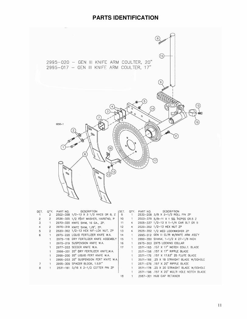
1. Assembly 3/8 x 2-1/2” roll pin into hole closest to end of 1-1/2” diameter shank, leaving approximately equal amount protruding out each side. Note: offset shanks require that you perform step 2 first then step 1.
2. Insert lock collar into pivot casting and slide shank up through casting and lock collar.
If you wish to lock coulter from pivoting, slide roll pin into slots in casting. If you wish to let coulter pivot, do not align roll pin with casting slots, but slide shank up till roll pin contacts casting surface. Install and tighten 5/8 x 1” setscrew in lock collar to 110 ft. lb. torque maximum.
3. Mount 17” blade loosely to hub using four 1/2 x 1-1/2” carriage bolts, lock washers and
nuts. 4. Mount fertilizer knife and spacer block to rear support arm using two 1/2 bolts lock
nuts. Place shims between 2995-309 – Spacer Block and support arm as required to align knife point with blade.
5. Center blade on hub by rotating blade and watching clearance between knife and
blade. Slide blade on hub as required until clearance varies no more than 1/8” when blade is rotated one complete revolution. Tighten four 1/2” nuts. If blade-wobble is excessive, check for burrs on hub mounting surface and remove if necessary.
6. Adjust knife clearance to blade as close as possible. The high point of the blade
should just clear the knife as blade is rotated. Be sure blade rotates freely then tighten two 1/2” locknuts to 120 ft. lb. Re-check clearance, by rotating blade one full revolution, after all bolts are tightened.
7. Assemble clamp components loosely to planter front bar as shown in parts view of
appropriate clamp. 8. Position coulter clamps either toward the inside or outside of the planter openers on
each side of the planter to equalize draft. Tighten four 1/2” nuts to secure the clamps. 9. Install coulters on planter by inserting shank up through clamps and tightening 5/8 x 1”
setscrews. 10. Install 5/16 x 2-1/2” cotter pins in all vertical 1-1/2” diameter shanks. This cotter pin
prevents loss of coulter should the clamp setscrews work loose. Cotter pin can be installed between clamp castings or on top, above top casting depending on the shank.
11. Set coulter depth by loosening setscrews in clamp castings. For John Deere 7000
front fold planters there may not be enough up adjustment to operate coulter at proper depth, not more than hub deep. Not all toolbars on John Deere planters operate at the same height. If necessary, cut off top of 1/12” diameter shank to allow proper adjustment.

7
INSTALLATION 12. On John Deere 7000 front fold planters there are two hoses that may interfere with
coulter operation. Loosen hydraulic fittings and swivel hoses up out of the way to provide clearance when coulter flexes up.
13. If you have elected to let coulter swivel, set lock collar to allow swivel in one or both directions as required. If you have elected to hold coulter rigid, set coulter straight with the direction of travel. Tighten set screw to 110 ft. lb. torque maximum.
14. Set spring tension by adjusting 3/4” lock nut until 1/8” of threads are exposed above the nut. Tighten 3/4” locknut if greater spring pre-load is required. NOTE: This will reduce vertical movement of coulter.
15. NEVER mount coulters under planter drive shaft to allow coulter blades to contact shaft when an obstacle is struck. Coulters must be mounted so blade can always flex up and clear drive shaft.
NOTE: Dry fertilizer must be free of chunks greater that 1/4” in size to prevent plugging. Yetter recommends using screened fertilizer or running fertilizer through screen when hoppers are filled. Clean hoppers thoroughly at the beginning of season to prevent plugging problems.
The rubber dry fertilizer tube may appear to be ‘stretched’ when the planter is in the transport position. This does not affect operation of the planter and should not be detrimental to the fertilizer tube.
OPERATION
Yetter Model Generation III fertilizer coulters are designed to apply fertilizer 3” to 5” deep. See your fertilizer dealer for recommended depth and distance away from row for your particular fertilizer. A popular placement setting is 2” below and 2” away from the seed. High deposit rates require the fertilizer to be placed farther away from the row to avoid crop “burn”.
The coulter can be set up to swivel or not swivel as required. By not allowing the coulter to swivel, the distance between seed and fertilizer varies less when planting on contour.
When mounting Model Generation III coulters on 3-point or 2-point hitch planters, the coulters should be set up to swivel, particularly if a 4-wheel drive tractor is used. This reduces the side load on the coulter during operation. It is preferable to allow the coulter to swivel.
IMPORTANT: For proper operation, the planter frame must operate level and at the correct height, usually 20” – 22” while in operation.
In hard no-till conditions the desired operating depth may not be possible. Tighten spring nut to maintain depth if spring is flexing rather than lower coulter to obtain maximum depth. Planter weight may limit operating depth in hard conditions, particularly with mounted or semi-mounted planters. Be sure planter has enough weight to keep drive wheels on the ground during operation or plant populations can be drastically affected.

8
OPERATION
1. Set coulter blades to run vertical to ground. Operation depth and blade wear can be affected if coulter is mounted crooked. If coulters are set-up to not swivel be sure they run straight with the direction of travel.
2. After a few hours use, check all bolts and setscrews for tightness. 3. After a few days use, check coulter hubs for loose bearings. There should be no end play in the hub
bearings to allow it to wobble. If necessary, remove hub cap and cotter pin, adjust slotted nut to remove wobble, re-insert cotter pin and replace hub cap.
4. KNIFE ADJUSTMENT IS CRITICAL. Adjust knife-blade clearance regularly, see page 9.
An optional knife scraper, Part #2970-133 or 2976-133 is available to reduce the frequency of adjustment on the fertilizer coulter knife. In addition this allows better operation in tough conditions such as freshly disked soils with abundant trash in the top four inches of loose soil. NOTE: A ‘bump’ will appear behind knife scraper, on blade where protected, this must be ground off periodically to maintain correct knife-blade clearance.
5. BLADE WEAR can affect operation in loose trash conditions. If knife adjustment does not stop
plugging problems, it may be necessary to replace blade. 6. Dry fertilizer must be free of chunks greater that 1/4” in size to prevent plugging. Yetter
recommends using screened fertilizer or running fertilizer through screen when hoppers are filled. Clean hoppers thoroughly at the beginning of season to prevent plugging problems.
NOTE: The rubber dry fertilizer tube may appear to be ‘stretched’ when the planter is in the transport position. This does not affect operation of the planter and should not be detrimental to the fertilizer tube.
2970-133 17” Knife Scraper Key Qty. Part No. Description 1 1 2970-353 Double Edge Knife Scraper 2 1 2502-199 5/16-18 x 3/4 HHCS Gr. 5 ZP 3 1 2526-201 5/16 Std. Flat washer ZP 4 1 2520-205 5/16-18 Lock Hex Nut ZP
2976-133 20” Knife Scraper Key Qty. Part No. Description 1 1 2976-353 Double Edge Knife Scraper 2 1 2502-199 5/16-18 x 3/4 HHCS Gr. 5 ZP 3 1 2526-201 5/16 Std. Flat washer ZP 4 1 2520-205 5/16-18 Lock Hex Nut ZP
9
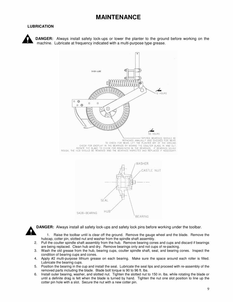
MAINTENANCE
LUBRICATION
DANGER: Always install safety lock-ups or lower the planter to the ground before working on the machine. Lubricate at frequency indicated with a multi-purpose type grease.
DANGER: Always install all safety lock-ups and safety lock pins before working under the toolbar.
1. Raise the toolbar until is clear off the ground. Remove the gauge wheel and the blade. Remove the hubcap, cotter pin, slotted nut and washer from the spindle shaft assembly.
2. Pull the coulter spindle shaft assembly from the hub. Remove bearing cones and cups and discard if bearings are being replaced. Clean hub and dry. Remove bearings only and not cups of re-packing.
3. Wash the old grease from the hub, bearing cups, coulter spindle shaft, seal, and bearing cones. Inspect the condition of bearing cups and cones.
4. Apply #2 multi-purpose lithium grease on each bearing. Make sure the space around each roller is filled. Lubricate the bearing cups.
5. Position the bearing in the cup and install the seal. Lubricate the seal lips and proceed with re-assembly of the removed parts including the blade. Blade bolt torque is 90 to 96 ft. lbs.
6. Install outer bearing, washer, and slotted nut. Tighten the slotted nut to 150 in. lbs. while rotating the blade or until a definite drag is felt when the blade is turned by hand. Tighten the nut one slot position to line up the cotter pin hole with a slot. Secure the nut with a new cotter pin.

10
KNIFE ADJUSTMENT
The adjustment of knife clearance to the blade is critical to trouble free operation of the fertilizer coulter, in certain conditions the coulter can “plug” in just a few feet if not correctly adjusted. 1. The disc blade must run concentric. Adjust by loosening four hub nuts and centering the blade. 2. Set knife to rub slightly on blade, especially at bottom of knife. See illustrations above. Tighten lock
nuts securely.
11
PARTS IDENTIFICATION
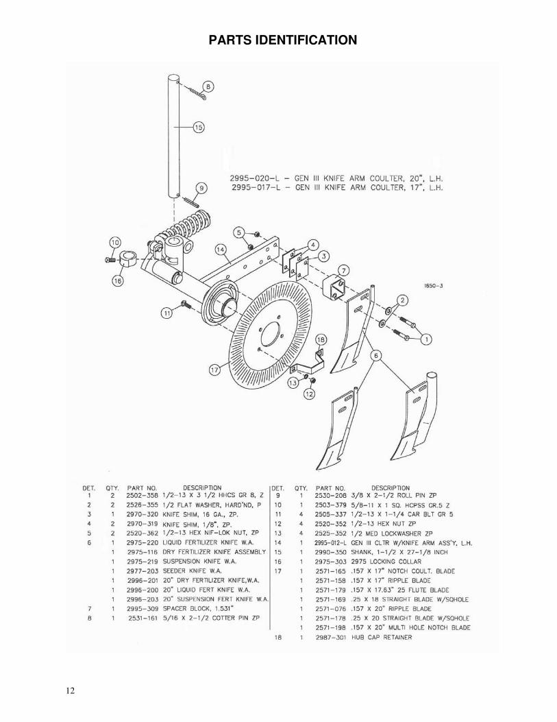
12
PARTS IDENTIFICATION
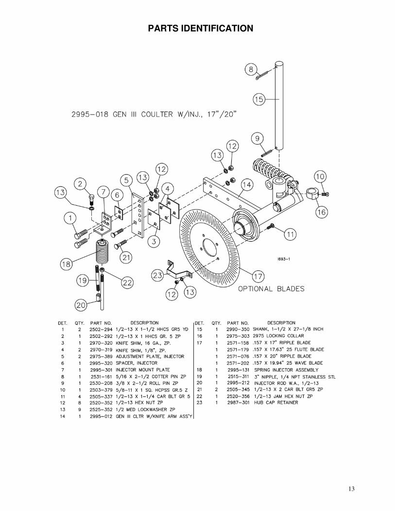
13
PARTS IDENTIFICATION
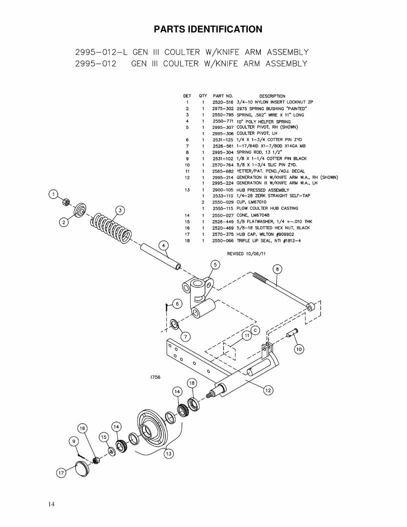
14
PARTS IDENTIFICATION
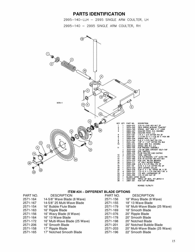
15
PARTS IDENTIFICATION
ITEM #24 – DIFFERENT BLADE OPTIONS PART NO. DESCRIPTION 2571-164 14-5/8” Wave Blade (8 Wave) 2571-167 14-5/8” 25 Multi-Wave Blade 2571-154 16” Bubble Flute Blade 2571-163 16” Ripple Blade 2571-156 16” Wavy Blade (8 Wave) 2571-164 16” 13 Wave Blade 2571-172 16” Multi-Wave Blade (25 Wave) 2571-206 16” Smooth Blade 2571-158 17” Ripple Blade 2571-165 17” Notched Smooth Blade
PART NO. DESCRIPTION 2571-156 18” Wavy Blade (8 Wave) 2571-155 18” 13 Wave Blade 2571-179 18” Multi-Wave Blade (25 Wave) 2571-169 18” Smooth Blade 2571-076 20” Ripple Blade 2571-178 20” Smooth Blade 2571-198 20” Notched Blade 2571-201 20” Notched Bubble Blade 2571-203 20” Multi-Wave Blade (25 Wave) 2571-196 22” Smooth Blade
16
PARTS IDENTIFICATION
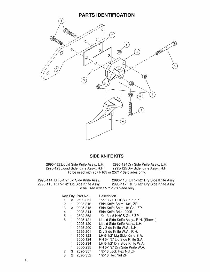
SIDE KNIFE KITS 2995-122 Liquid Side Knife Assy., L.H. 2995-124 Dry Side Knife Assy., L.H. 2995-123 Liquid Side Knife Assy., R.H. 2995-125 Dry Side Knife Assy., R.H.
To be used with 2571-165 or 2571-169 blades only.
2996-114 LH 5-1/2” Liq Side Knife Assy. 2996-116 LH 5-1/2” Dry Side Knife Assy. 2996-115 RH 5-1/2” Liq Side Knife Assy. 2996-117 RH 5-1/2” Dry Side Knife Assy.
To be used with 2571-178 blade only.
Key Qty. Part No. Description 1 3 2502-351 1/2-13 x 2 HHCS Gr. 5 ZP 2 1 2995-316 Side Knife Shim, 1/8”, ZP
3 3 2995-315 Side Knife Shim, 16 Ga., ZP 4 1 2995-314 Side Knife Brkt., 2995 5 1 2502-362 1/2-13 x 5 HHCS Gr. 5 ZP 6 1 2995-121 Liquid Side Knife Assy., R.H. (Shown) 1 2995-120 Liquid Side Knife Assy., L.H. 1 2995-200 Dry Side Knife W.A., L.H. 1 2995-201 Dry Side Knife W.A., R.H. 1 3000-123 LH 5-1/2” Liq Side Knife S.A. 1 3000-124 RH 5-1/2” Liq Side Knife S.A. 1 3000-234 LH 5-1/2” Dry Side Knife W.A. 1 3000-235 RH 5-1/2” Dry Side Knife W.A. 7 3 2520-357 1/2-13 Lock Hex Nut ZP 8 2 2520-352 1/2-13 Hex Nut ZP
17
PARTS IDENTIFICATION
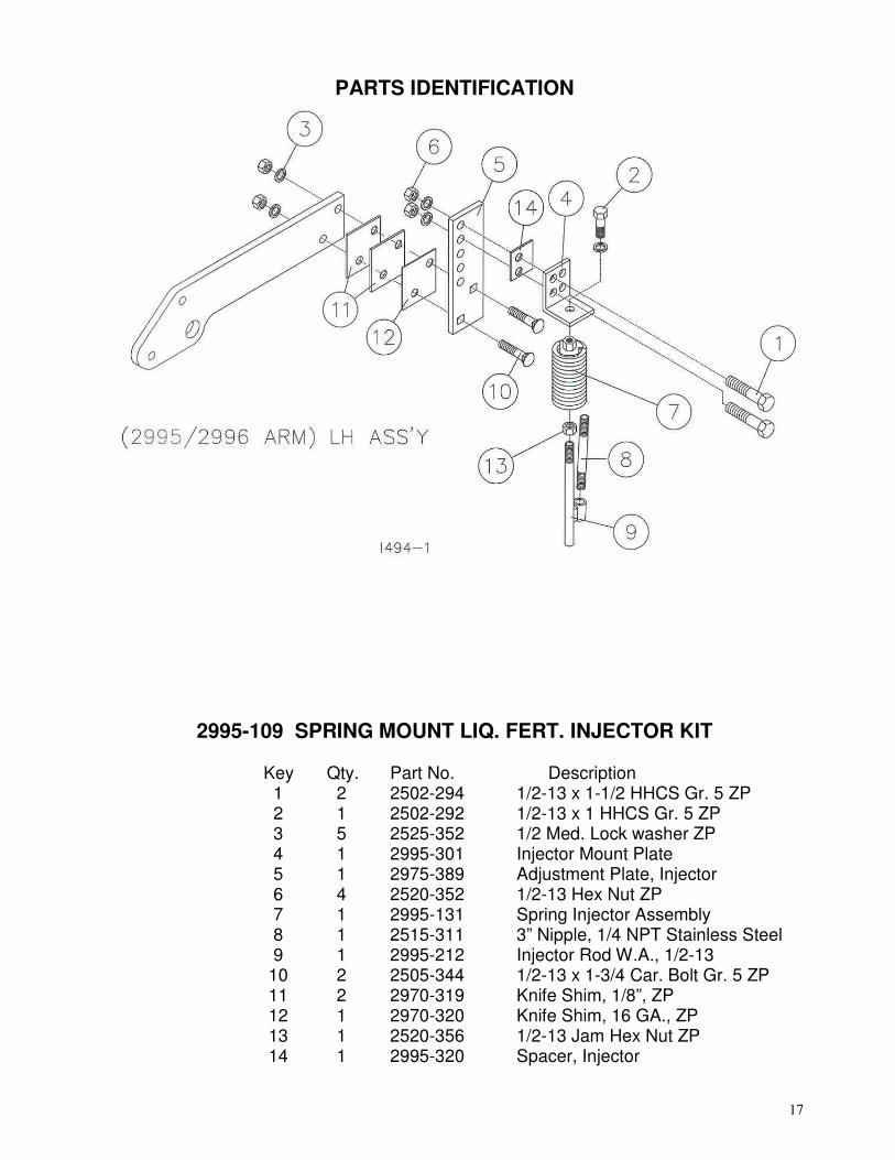
2995-109 SPRING MOUNT LIQ. FERT. INJECTOR KIT Key Qty. Part No. Description 1 2 2502-294 1/2-13 x 1-1/2 HHCS Gr. 5 ZP
2 1 2502-292 1/2-13 x 1 HHCS Gr. 5 ZP 3 5 2525-352 1/2 Med. Lock washer ZP
4 1 2995-301 Injector Mount Plate 5 1 2975-389 Adjustment Plate, Injector
6 4 2520-352 1/2-13 Hex Nut ZP 7 1 2995-131 Spring Injector Assembly
8 1 2515-311 3” Nipple, 1/4 NPT Stainless Steel 9 1 2995-212 Injector Rod W.A., 1/2-13 10 2 2505-344 1/2-13 x 1-3/4 Car. Bolt Gr. 5 ZP 11 2 2970-319 Knife Shim, 1/8”, ZP 12 1 2970-320 Knife Shim, 16 GA., ZP
13 1 2520-356 1/2-13 Jam Hex Nut ZP 14 1 2995-320 Spacer, Injector
18
PARTS IDENTIFICATION
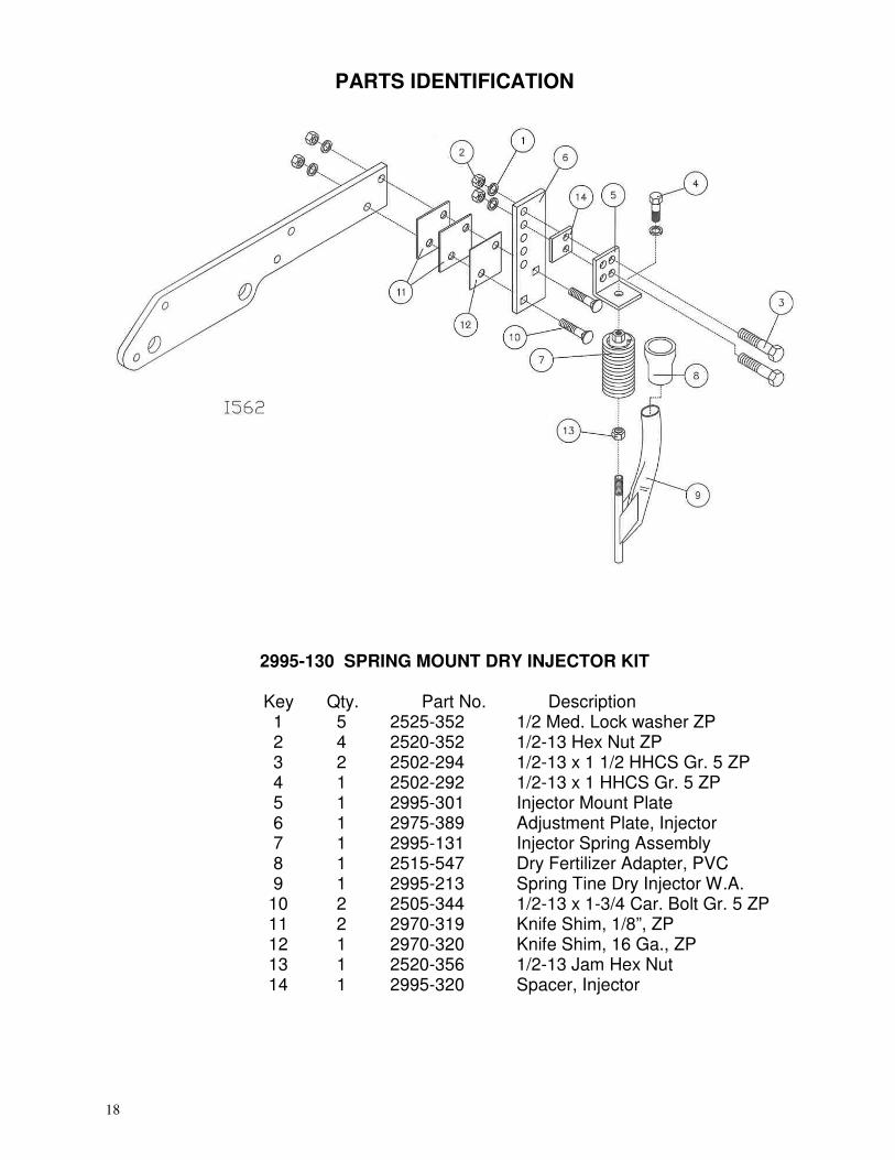
2995-130 SPRING MOUNT DRY INJECTOR KIT Key Qty. Part No. Description 1 5 2525-352 1/2 Med. Lock washer ZP 2 4 2520-352 1/2-13 Hex Nut ZP 3 2 2502-294 1/2-13 x 1 1/2 HHCS Gr. 5 ZP 4 1 2502-292 1/2-13 x 1 HHCS Gr. 5 ZP 5 1 2995-301 Injector Mount Plate 6 1 2975-389 Adjustment Plate, Injector 7 1 2995-131 Injector Spring Assembly 8 1 2515-547 Dry Fertilizer Adapter, PVC 9 1 2995-213 Spring Tine Dry Injector W.A. 10 2 2505-344 1/2-13 x 1-3/4 Car. Bolt Gr. 5 ZP 11 2 2970-319 Knife Shim, 1/8”, ZP 12 1 2970-320 Knife Shim, 16 Ga., ZP 13 1 2520-356 1/2-13 Jam Hex Nut 14 1 2995-320 Spacer, Injector
19
PARTS IDENTIFICATION
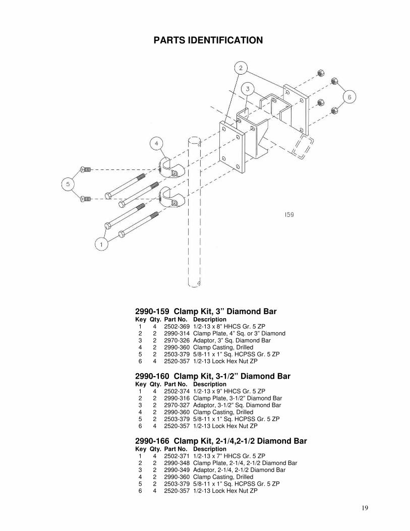
2990-159 Clamp Kit, 3” Diamond Bar Key Qty. Part No. Description 1 4 2502-369 1/2-13 x 8” HHCS Gr. 5 ZP 2 2 2990-314 Clamp Plate, 4” Sq. or 3” Diamond 3 2 2970-326 Adaptor, 3” Sq. Diamond Bar 4 2 2990-360 Clamp Casting, Drilled 5 2 2503-379 5/8-11 x 1” Sq. HCPSS Gr. 5 ZP 6 4 2520-357 1/2-13 Lock Hex Nut ZP
2990-160 Clamp Kit, 3-1/2” Diamond Bar Key Qty. Part No. Description 1 4 2502-374 1/2-13 x 9” HHCS Gr. 5 ZP 2 2 2990-316 Clamp Plate, 3-1/2” Diamond Bar 3 2 2970-327 Adaptor, 3-1/2” Sq. Diamond Bar 4 2 2990-360 Clamp Casting, Drilled 5 2 2503-379 5/8-11 x 1” Sq. HCPSS Gr. 5 ZP 6 4 2520-357 1/2-13 Lock Hex Nut ZP
2990-166 Clamp Kit, 2-1/4,2-1/2 Diamond Bar Key Qty. Part No. Description 1 4 2502-371 1/2-13 x 7” HHCS Gr. 5 ZP 2 2 2990-348 Clamp Plate, 2-1/4, 2-1/2 Diamond Bar 3 2 2990-349 Adaptor, 2-1/4, 2-1/2 Diamond Bar 4 2 2990-360 Clamp Casting, Drilled 5 2 2503-379 5/8-11 x 1” Sq. HCPSS Gr. 5 ZP
6 4 2520-357 1/2-13 Lock Hex Nut ZP
20
PARTS IDENTIFICATION
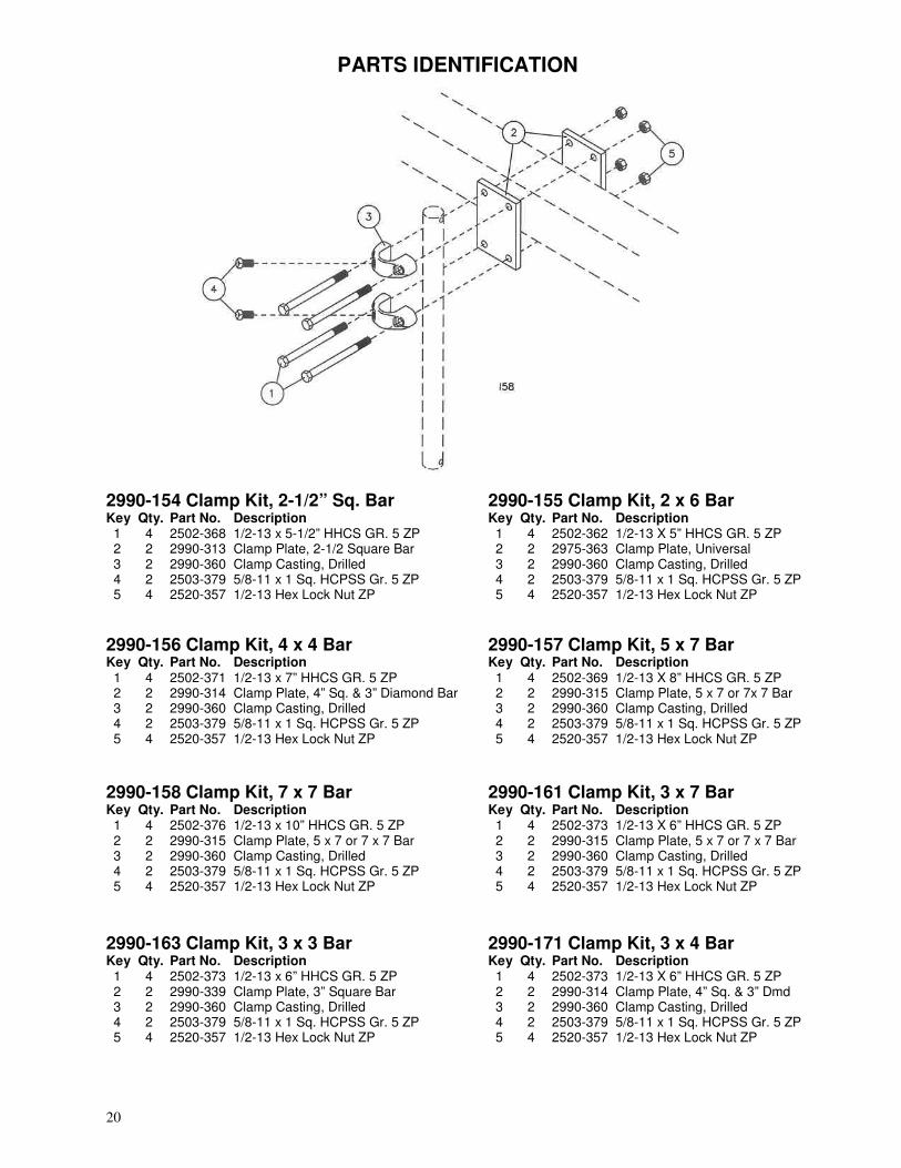
2990-154 Clamp Kit, 2-1/2” Sq. Bar 2990-155 Clamp Kit, 2 x 6 Bar Key Qty. Part No. Description Key Qty. Part No. Description 1 4 2502-368 1/2-13 x 5-1/2” HHCS GR. 5 ZP 1 4 2502-362 1/2-13 X 5” HHCS GR. 5 ZP 2 2 2990-313 Clamp Plate, 2-1/2 Square Bar 2 2 2975-363 Clamp Plate, Universal 3 2 2990-360 Clamp Casting, Drilled 3 2 2990-360 Clamp Casting, Drilled 4 2 2503-379 5/8-11 x 1 Sq. HCPSS Gr. 5 ZP 4 2 2503-379 5/8-11 x 1 Sq. HCPSS Gr. 5 ZP 5 4 2520-357 1/2-13 Hex Lock Nut ZP 5 4 2520-357 1/2-13 Hex Lock Nut ZP
2990-156 Clamp Kit, 4 x 4 Bar 2990-157 Clamp Kit, 5 x 7 Bar Key Qty. Part No. Description Key Qty. Part No. Description 1 4 2502-371 1/2-13 x 7” HHCS GR. 5 ZP 1 4 2502-369 1/2-13 X 8” HHCS GR. 5 ZP 2 2 2990-314 Clamp Plate, 4” Sq. & 3” Diamond Bar 2 2 2990-315 Clamp Plate, 5 x 7 or 7x 7 Bar 3 2 2990-360 Clamp Casting, Drilled 3 2 2990-360 Clamp Casting, Drilled 4 2 2503-379 5/8-11 x 1 Sq. HCPSS Gr. 5 ZP 4 2 2503-379 5/8-11 x 1 Sq. HCPSS Gr. 5 ZP 5 4 2520-357 1/2-13 Hex Lock Nut ZP 5 4 2520-357 1/2-13 Hex Lock Nut ZP
2990-158 Clamp Kit, 7 x 7 Bar 2990-161 Clamp Kit, 3 x 7 Bar Key Qty. Part No. Description Key Qty. Part No. Description 1 4 2502-376 1/2-13 x 10” HHCS GR. 5 ZP 1 4 2502-373 1/2-13 X 6” HHCS GR. 5 ZP 2 2 2990-315 Clamp Plate, 5 x 7 or 7 x 7 Bar 2 2 2990-315 Clamp Plate, 5 x 7 or 7 x 7 Bar 3 2 2990-360 Clamp Casting, Drilled 3 2 2990-360 Clamp Casting, Drilled 4 2 2503-379 5/8-11 x 1 Sq. HCPSS Gr. 5 ZP 4 2 2503-379 5/8-11 x 1 Sq. HCPSS Gr. 5 ZP 5 4 2520-357 1/2-13 Hex Lock Nut ZP 5 4 2520-357 1/2-13 Hex Lock Nut ZP
2990-163 Clamp Kit, 3 x 3 Bar 2990-171 Clamp Kit, 3 x 4 Bar Key Qty. Part No. Description Key Qty. Part No. Description 1 4 2502-373 1/2-13 x 6” HHCS GR. 5 ZP 1 4 2502-373 1/2-13 X 6” HHCS GR. 5 ZP 2 2 2990-339 Clamp Plate, 3” Square Bar 2 2 2990-314 Clamp Plate, 4” Sq. & 3” Dmd 3 2 2990-360 Clamp Casting, Drilled 3 2 2990-360 Clamp Casting, Drilled 4 2 2503-379 5/8-11 x 1 Sq. HCPSS Gr. 5 ZP 4 2 2503-379 5/8-11 x 1 Sq. HCPSS Gr. 5 ZP 5 4 2520-357 1/2-13 Hex Lock Nut ZP 5 4 2520-357 1/2-13 Hex Lock Nut ZP
21
PARTS IDENTIFICATION
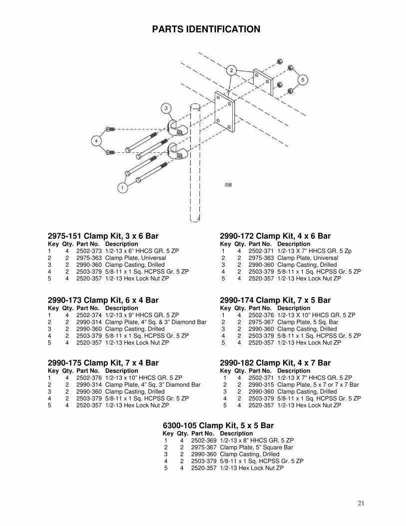
2975-151 Clamp Kit, 3 x 6 Bar 2990-172 Clamp Kit, 4 x 6 Bar Key Qty. Part No. Description Key Qty. Part No. Description 1 4 2502-373 1/2-13 x 6” HHCS GR. 5 ZP 1 4 2502-371 1/2-13 X 7” HHCS GR. 5 Zp 2 2 2975-363 Clamp Plate, Universal 2 2 2975-363 Clamp Plate, Universal 3 2 2990-360 Clamp Casting, Drilled 3 2 2990-360 Clamp Casting, Drilled 4 2 2503-379 5/8-11 x 1 Sq. HCPSS Gr. 5 ZP 4 2 2503-379 5/8-11 x 1 Sq. HCPSS Gr. 5 ZP 5 4 2520-357 1/2-13 Hex Lock Nut ZP 5 4 2520-357 1/2-13 Hex Lock Nut ZP
2990-173 Clamp Kit, 6 x 4 Bar 2990-174 Clamp Kit, 7 x 5 Bar Key Qty. Part No. Description Key Qty. Part No. Description 1 4 2502-374 1/2-13 x 9” HHCS GR. 5 ZP 1 4 2502-376 1/2-13 X 10” HHCS GR. 5 ZP 2 2 2990-314 Clamp Plate, 4” Sq. & 3” Diamond Bar 2 2 2975-367 Clamp Plate, 5 Sq. Bar 3 2 2990-360 Clamp Casting, Drilled 3 2 2990-360 Clamp Casting, Drilled 4 2 2503-379 5/8-11 x 1 Sq. HCPSS Gr. 5 ZP 4 2 2503-379 5/8-11 x 1 Sq. HCPSS Gr. 5 ZP 5 4 2520-357 1/2-13 Hex Lock Nut ZP 5 4 2520-357 1/2-13 Hex Lock Nut ZP
2990-175 Clamp Kit, 7 x 4 Bar 2990-182 Clamp Kit, 4 x 7 Bar Key Qty. Part No. Description Key Qty. Part No. Description 1 4 2502-376 1/2-13 x 10” HHCS GR. 5 ZP 1 4 2502-371 1/2-13 X 7” HHCS GR. 5 ZP 2 2 2990-314 Clamp Plate, 4” Sq. 3” Diamond Bar 2 2 2990-315 Clamp Plate, 5 x 7 or 7 x 7 Bar 3 2 2990-360 Clamp Casting, Drilled 3 2 2990-360 Clamp Casting, Drilled 4 2 2503-379 5/8-11 x 1 Sq. HCPSS Gr. 5 ZP 4 2 2503-379 5/8-11 x 1 Sq. HCPSS Gr. 5 ZP 5 4 2520-357 1/2-13 Hex Lock Nut ZP 5 4 2520-357 1/2-13 Hex Lock Nut ZP
6300-105 Clamp Kit, 5 x 5 Bar Key Qty. Part No. Description
1 4 2502-369 1/2-13 x 8” HHCS GR. 5 ZP 2 2 2975-367 Clamp Plate, 5” Square Bar 3 2 2990-360 Clamp Casting, Drilled 4 2 2503-379 5/8-11 x 1 Sq. HCPSS Gr. 5 ZP 5 4 2520-357 1/2-13 Hex Lock Nut ZP

22
TROUBLESHOOTING
Problem Setting coulter Trash plugging Blade not penetrating Spring not deflecting Fertilizer too deep Fertilizer too shallow Fertilizer will not flow Blade not rotating properly
Cause Planter not set correctly Excessive knife-blade clearance Knife not correctly aligned behind blade Insufficient coulter spring pressure Coulter incorrectly installed Excessive spring pressure Spring not deflecting Coulter incorrectly installed Lack of depth control Planter frame too low Blade not penetrating Coulter incorrectly installed Plugged fertilizer tubes Loose soil
Solution Ensure that in operation the planter frame is at correct height (20”-22”) and level the toolbar. See opposite page. Check and adjust knife-blade clearance. See page 9. Use shims to align knife behind blade Tighten coulter spring locknut down 1” further Adjust height of coulter by sliding shank down Back off coulter spring locknut to 1/8” of thread exposed Back off coulter spring locknut to 1/8” of thread exposed Adjust height of coulter by sliding shank up Install gauge wheel kit, part no. 2975-120 Raise planter frame to correct height Tighten coulter spring locknut down 1” further Adjust height of coulter by sliding shank down Check for plugged fertilizer tube openings on knife Check for plugged fertilizer delivery tubes on planter Coulter works best in firmer soil conditions

23
NOTES

24
Our name Is getting known
Just a few years ago, Yetter products were sold primarily to the Midwest only. Then we embarked on a program of expansion and moved into the East, the South, the West and now north into Canada. We’re even getting orders from as far away as Australia and Africa. So, when you buy Yetter products . . .you’re buying a
name that’s recognized. A name that’s known and respected. A name that’s become a part of American agriculture and has become synonymous with quality and satisfaction in the field of conservation tillage. Thank you.
YETTER MANUFACTURING CO. Colchester, IL 62326-0358 � 309/776-4111
Toll Free 800/447-5777 Fax 309/776-3222
Website: www.yetterco.com E-mail: [email protected]
2565-490_REV_D
� 07/13