planting components - great plains manufacturing ... · 204-219l left hand dry fertilizer coulter...
TRANSCRIPT
Cover illustration may show optional equipment not supplied with standard unit.
!Read the operator’s manual entirely. When you see this symbol, the subsequentinstructions and warnings are serious - follow without exception. Your life andthe lives of others depend on it!
© Copyright 2002 Printed 3/24/2003
11160
204-310M
Operator’s/Parts ManualVantage II
Planting Components

Table of Contents
© Copyright 2002 All rights Reserved
Great Plains Manufacturing, Inc. provides this publication “as is” without warranty of any kind, either expressed or implied. While every precaution has been taken in thepreparation of this manual, Great Plains Manufacturing, Inc. assumes no responsibility for errors or omissions. Neither is any liability assumed for damages resulting fromthe use of the information contained herein. Great Plains Manufacturing, Inc. reserves the right to revise and improve its products as it sees fit. This publication describesthe state of this product at the time of its publication, and may not reflect the product in the future.
Great Plains Manufacturing, Incorporated TrademarksThe following are trademarks of Great Plains Mfg., Inc.: Application Systems, Ausherman, Land Pride, Great Plains
All other brands and product names are trademarks or registered trademarks of their respective holders.
Printed in the United States of America.
204-310M4/26/2006
General Information . . . . . . . . . . . . . . . . . . . . . . . . .1
Using this Manual . . . . . . . . . . . . . . . . . . . . . . . . . . .1
Introduction . . . . . . . . . . . . . . . . . . . . . . . . . . . . . . . .1
Important Safety Information . . . . . . . . . . . . . . . . . .3
Owner’s Assistance . . . . . . . . . . . . . . . . . . . . . . . . .4
Operating and Assembly Instructions. . . . . . . . . . .5
General Operation & Repair . . . . . . . . . . . . . . . . .5
Adjustments . . . . . . . . . . . . . . . . . . . . . . . . . . . . . . .7
Spring Adjustments . . . . . . . . . . . . . . . . . . . . . . .7
Fertilizer Tube Adjustments . . . . . . . . . . . . . . . . . .7
Maintenance & Lubrication . . . . . . . . . . . . . . . . . . .8
Maintenance . . . . . . . . . . . . . . . . . . . . . . . . . . . . .8
Storage . . . . . . . . . . . . . . . . . . . . . . . . . . . . . . . . .8
Lubrication . . . . . . . . . . . . . . . . . . . . . . . . . . . . . .8
Parts . . . . . . . . . . . . . . . . . . . . . . . . . . . . . . . . . . . . .10
Vantage ll Coulter . . . . . . . . . . . . . . . . . . . . . . . .10
Rectangular Tubing Clamp Kits . . . . . . . . . . . . .12
Extension Brackets . . . . . . . . . . . . . . . . . . . . . . .14
Specifications . . . . . . . . . . . . . . . . . . . . . . . . . . . . .22
Appendix . . . . . . . . . . . . . . . . . . . . . . . . . . . . . . . . .23
Warranty . . . . . . . . . . . . . . . . . . . . . . . . . . . . . . . . . .24

4/26/2006 204-310M
1General Information
Important NoticeGreat Plains Manufacturing, Inc. provides thispublication “as is” without warranty of any kind,either expressed or implied, while everyprecaution has been taken in the preparation ofthis manual, Great Plains Manufacturing, Inc.assumes no responsibility for errors or omissions.Neither is any liability assumed for damagesresulting from the use of the informationcontained herein. Great Plains Manufacturing,Inc. reserves the right to revise and improve itsproducts as it sees fit. This publication describesthe state of this product at the time of itspublication, and may not reflect the product at alltimes in the future.
Printed in the United States of America.
For your convenience, record your Model and theDate Purchased on page 4. Have this informationbefore you when calling a Great Plains AuthorizedDealer.
This Operator’s Manual applies to theVantage II Fertilizer Coulter listed below:
204-218L Right Hand Dry Fertilizer Coulter
204-219L Left Hand Dry Fertilizer Coulter
Using this ManualFor your safety and to help in developing a betterunderstanding of your equipment we highlyrecommend that you read the operator sections ofthis manual. Reading these sections not onlyprovides valuable training but also familiarizesyou with helpful information and its location. Theparts sections are for reference only and don’trequire cover to cover reading. After reviewingyour manual store it in a dry, easily accessiblelocation for future reference.
General Information
! WARNINGGreat Plains denies any responsibility for damage caused to seed due to the improper application of liquid fertilizer or chemical.It is the sole responsibility of the user of liquid fertilizer or chemical for any damage incurred.

204-310M 4/26/2006
2
Introduction
Great Plains welcomes you to its growing family ofnew product owners. This Vantage II FertilizerCoulter has been designed with care and built byskilled workers using quality materials. Propersetup, maintenance and safe operating practiceswill help you get years of satisfactory use from themachine.
Description of UnitThe parts on your Vantage II Fertilizer Coulterhave been specially designed and should only bereplaced with genuine Great Plains parts.Therefore, should your Vantage II FertilizerCoulter require replacement parts go to yourGreat Plains Dealer.
Using This ManualThis manual will familiarize you with safety,assembly, operation, adjustments andmaintenance. Read this manual and follow therecommendations to help ensure safe andefficient operation.
The information in this manual is current atprinting. Some parts may change to assure topperformance.
DefinitionsThe following terms are used throughout thismanual.
Right-hand and left-hand as used in this manualare determined by facing the direction themachine will travel while in use unless otherwisestated.
IMPORTANT: A crucial point of informationrelated to the preceding topic. For safe andcorrect operation, read and follow thedirections provided before continuing.
NOTE: Useful information related to thepreceding topic.
! WARNINGGreat Plains denies any responsibility for damage caused to seed due to the improper application of liquid fertilizer or chemical.It is the sole responsibility of the user of liquid fertilizer or chemical for any damage incurred.

4/26/2006 204-310M
3Important Safety Information
Important Safety Information
!Look for Safety SymbolThe SAFETY ALERT SYMBOL indicates there isa potential hazard to personal safety involved andextra safety precaution must be taken. When yousee this symbol, be alert and carefully read themessage that follows it. In addition to design andconfiguration of equipment, hazard control andaccident prevention are dependent upon theawareness, concern, prudence and propertraining of personnel involved in the operation,transport, maintenance and storage ofequipment.
Be Aware of Signal WordsSignal words designate a degree or level ofhazard seriousness.
DANGER indicates an imminently hazardoussituation which, if not avoided, will result in deathor serious injury. This signal word is limited to themost extreme situations, typically for machinecomponents that, for functional purposes, cannotbe guarded.
WARNING indicates a potentially hazardoussituation which, if not avoided, could result indeath or serious injury, and includes hazards thatare exposed when guards are removed. It mayalso be used to alert against unsafe practices.
CAUTION indicates a potentially hazardoussituation which, if not avoided, may result in minoror moderate injury. It may also be used to alertagainst unsafe practices.
! CAUTION
! WARNING
! DANGER
! WARNINGGreat Plains denies any responsibility for damage caused to seed due to the improper application of liquid fertilizer or chemical.It is the sole responsibility of the user of liquid fertilizer or chemical for any damage incurred.

204-310M 4/26/2006
4
If you need customer service or repair parts,contact a Great Plains dealer. They have trainedpersonnel, repair parts and equipment speciallydesigned for Great Plains products.
Your machine’s parts were specially designed andshould only be replaced with Great Plains parts.Always use the model number when orderingparts from your Great Plains dealer.
Record your Model and Date Purchased here forquick reference:
Model :________________________________
Date Purchased:_________________________
Your Great Plains dealer wants you to be satis-fied with your new machine. If you do notunderstand any part of this manual or are not sat-isfied with the service received, please take thefollowing actions.
1. Discuss the matter with your dealershipservice manager. Make sure they are aware ofany problems so they can assist you.
2. If you are still unsatisfied, seek out the owneror general manager of the dealership.
3. For further assistance write to:
Product SupportGreat Plains Mfg. Inc., Service Department
P.O. Box 5060Salina, KS 67402-5060
Owner Assistance
! WARNINGGreat Plains denies any responsibility for damage caused to seed due to the improper application of liquid fertilizer or chemical.It is the sole responsibility of the user of liquid fertilizer or chemical for any damage incurred.
4/26/2006 204-310M
5Operating and Assembly Instructions
Operating and Assembly Instructions
! WARNINGGreat Plains denies any responsibility for damage caused to seed due to the improper application of liquid fertilizer or chemical.It is the sole responsibility of the user of liquid fertilizer or chemical for any damage incurred.
Most accidents are the result of negligence andcarelessness, usually caused by failure of theoperator to follow simple but necessary safetyprecautions. The following safety precautions aresuggested to help prevent such accidents. Thesafe operation of any machinery is a big concernto consumers and manufactures.Your Vantage IIFertilizer Coulter has been designed with manybuilt-in safety features. However, no one shouldoperate this product before carefully reading thisOperators Manual.
General Operation & RepairNever allow the Fertilizer Coulter to be operatedby anyone who is unfamiliar with the operation ofall functions of the unit. All operators should readand thoroughly understand the instructions givenin this manual prior to moving the unit.
1. Make sure safety rules are understood beforeoperating machinery or tractor.
2. Never permit any persons other than theoperator to ride on the tractor.
3. Never permit any persons to ride on or standnear the drill while it is in operation.
4. Regulate your speed to the field conditions,maintaining complete control at all times.
5. After repairing or adjusting, make sure alltools and parts are removed from theimplement before attempting to operate it.
6. Do not grease or oil machine while it is inoperation.
7. Loose fitting clothing should not be worn as itmay catch in moving parts.
8. Never dismount from a moving tractor.
9. Do not leave the tractor or the implementunattended with the engine running.
10. Do not stand between the tractor and theimplement during hitching.
11. Detach and store implements in an areawhere children normally do not play. Stabilizeimplements by using suitable supports andblock wheels.
204-310M 4/26/2006
6
12. If a hydraulic leak develops, correct itimmediately. Escaping hydraulic oil can haveextremely high pressure. A stream of highpressure oil may easily penetrate the skin aswith modern needle-less vaccinationequipment - but with the exception thathydraulic fluid may cause blood poisoning. Itis imperative that the connections are tightand that all lines and pipes are in goodcondition. If an injury is caused by theescaping hydraulic fluid, see doctor at once!
13. Use a piece of cardboard or wood to detectleaks of hydraulic oil under pressure.
14. Be sure to relieve all hydraulic pressure beforedisconnecting any lines or pipes between theimplement and the tractor hydraulic system.Keep all guards and shields in place.
Assembly InstructionsYour Vantage II Fertilizer Coulter comes to youcompletely assembled. Follow the instructionsbelow for mounting.
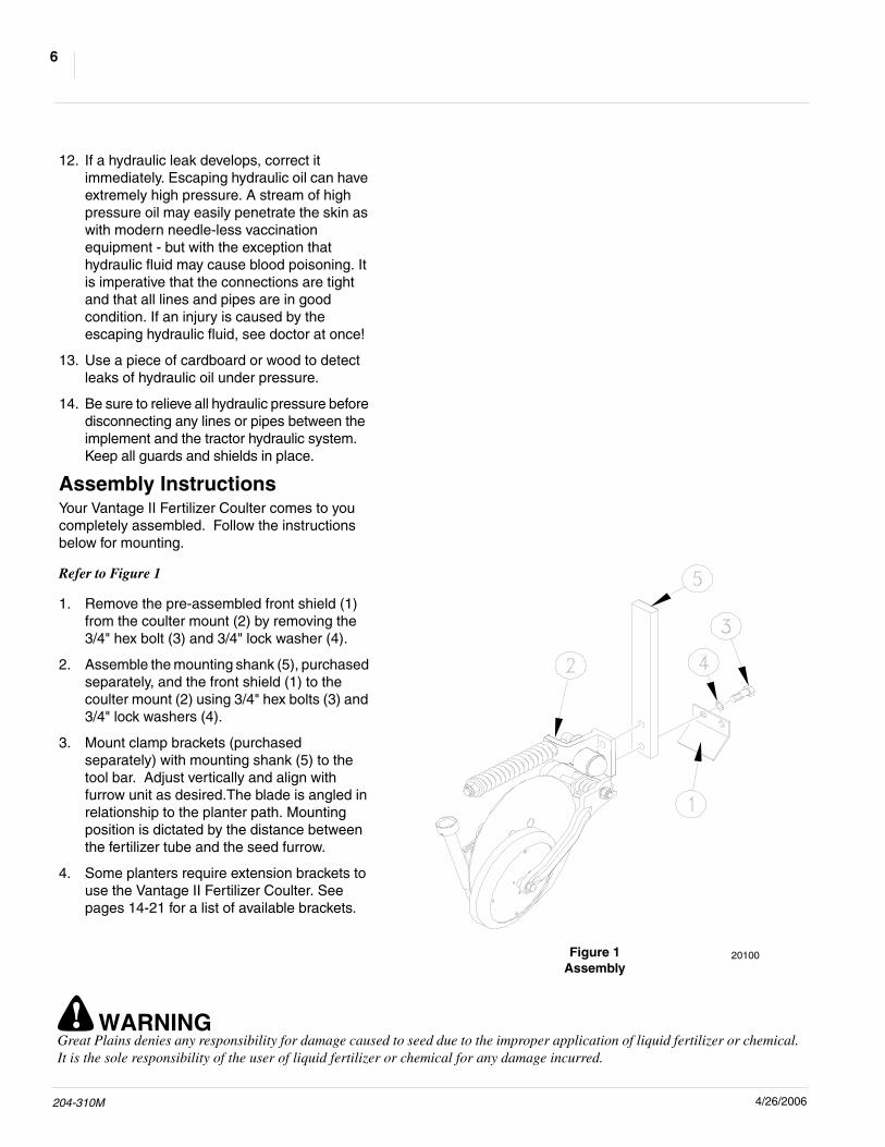
Refer to Figure 1
1. Remove the pre-assembled front shield (1)from the coulter mount (2) by removing the3/4" hex bolt (3) and 3/4" lock washer (4).
2. Assemble the mounting shank (5), purchasedseparately, and the front shield (1) to thecoulter mount (2) using 3/4" hex bolts (3) and3/4" lock washers (4).
3. Mount clamp brackets (purchasedseparately) with mounting shank (5) to thetool bar. Adjust vertically and align withfurrow unit as desired.The blade is angled inrelationship to the planter path. Mountingposition is dictated by the distance betweenthe fertilizer tube and the seed furrow.
4. Some planters require extension brackets touse the Vantage II Fertilizer Coulter. Seepages 14-21 for a list of available brackets.
Figure 1Assembly
20100
! WARNINGGreat Plains denies any responsibility for damage caused to seed due to the improper application of liquid fertilizer or chemical.It is the sole responsibility of the user of liquid fertilizer or chemical for any damage incurred.

4/26/2006 204-310M
7Adjustments
Spring AdjustmentsNo down pressure spring adjustment isnecessary on this unit. Initial operating force tomove coulter upwards is 428 pounds. Thepreload has proved to be more than adequate formost No-Till conditions. The torsion spring on thewheel arm requires no adjustment. This springapplies adequate down pressure to the wheel.This controls the soil from being pushed awayfrom the coulter blade, leaving the furrow asnarrow as possible.
! CAUTIONAny attempt to make coulter force greater than factorysetting, may contribute to premature failure of partsand warranty shall be null and void.
Fertilizer Tube AdjustmentAdjustments are made by starting with all threefertilizer tube mounting bolts tightened the sameamount, compressing the rubber slightly.
To move the fertilizer tube assembly toward thecoulter blade you can either loosen the front boltor tighten the two rear bolts evenly. To tilt thebottom of the tube toward the coulter blade, youcan either tighten the bottom rear bolt or loosenthe top rear bolt.
The desired running distance between the coulterblade and fertilizer tube assembly is from 1/16" to1/8".
Adjustments
! WARNINGGreat Plains denies any responsibility for damage caused to seed due to the improper application of liquid fertilizer or chemical.It is the sole responsibility of the user of liquid fertilizer or chemical for any damage incurred.

204-310M 4/26/2006
8
MaintenanceProper servicing and adjustment is the key to thelong life of any farm implement. With careful andsystematic inspection, you can avoid costlymaintenance, time and repair.
After using your Fertilizer Coulter for several hours,check all bolts to be sure they are tight.
1. Listed below are the items you need to lubricateevery 20 hours of operation. Use a heavy dutymultipurpose grease:
a. Grease zerk on hub.
b. Grease zerk on mounting casting
StorageClean the Fertilizer Coulter as necessary.
1. Lubricate zerks as indicated in the followingIllustrations.
2. Store the Fertilizer Coulter inside if possible forlonger Fertilizer Coulter life.
Lubrication
Lubrication is required every 20 hours of operation.
Lubrication Symbols
20
Maintenance and Lubrication
! WARNINGGreat Plains denies any responsibility for damage caused to seed due to the improper application of liquid fertilizer or chemical.It is the sole responsibility of the user of liquid fertilizer or chemical for any damage incurred.

4/26/2006 204-310M
9Maintenance and Lubrication
20Swivel Mounting Casting
Type of Lubrication: Heavy duty multipurpose grease
20Hub
Type of Lubrication: Heavy duty multipurpose grease
12799
12798
! WARNINGGreat Plains denies any responsibility for damage caused to seed due to the improper application of liquid fertilizer or chemical.It is the sole responsibility of the user of liquid fertilizer or chemical for any damage incurred.

204-310M 4/26/2006
10
11158
Parts
Vantage II Coulter

4/26/2006 204-310M
11Parts
1. 807-124C 21 FB ANGLED COULTER SHANK2. 820-181C VANII 5IN OFFSET FLAT SHANK RH Shown. White Planters.
820-182C VANII 5IN OFFSET FLAT SHANK LH3. 804-022C WASHER LOCK SPRING 5/8 PLT4. 803-021C NUT HEX 5/8-11 PLT5. 802-064C HHCS 3/4-10X2 GR56. 804-023C WASHER LOCK SPRING 3/4 PLT7. 204-154D FRONT SHIELD8. 804-025C WASHER FLAT 3/4 SAE PLT9. 817-051C SWING ARM BUSHING10. 204-209H BLADE SPRING ROD WELDMENT11. 204-233V COULTER PIVOT RH SUB-ASSY Shown.
204-235V COULTER PIVOT LH SUB-ASSY12. 200-001D HUB GREASE CAP13. 805-017C PIN COTTER 3/16 X 1 3/4 PLT14. 803-029C NUT HEX SLOTTED 7/8-14 PLT15. 804-055C WASHER SPINDLE - 7/816. 822-021C BEARING CONE LM-6704817. 816-009C OIL SEAL DOUBLE LIP18. 805-063C PIN COTTER 3/32 X 1 LOpfNG19. 204-234V BLADE ARM RH SUB-ASSY Shown.
204-236V BLADE ARM LH SUB-ASSY20. 817-029C BUSHING COULTER CASTING21. 807-074C SPRING 2.25 OD X .5 COIL22. 204-107D SPRING ROD SLEEVE 1 1/8 OD23. 812-031C CASTING COULTER SPRING WASHER24. 803-025C NUT HEX 3/4-10 PLT NYLOCK25. 817-084C PARALLEL ARM PIVOT BUSHING26. 807-089C TORSION SPRING 3/8WIRE RH Shown
807-090C TORSION SPRING 3/8WIRE LH27. 820-093C SINGLE BEVEL 18 COULTER BLADE28. 802-354C PLOW 1/2-13X1 1/2 GR529. 204-145D COULTER HUB30. 804-015C WASHER LOCK SPRING 1/2 PLT31. 803-020C NUT HEX 1/2-13 PLT32. 802-281C HHCS 5/8-11X2 3/4 GR533. 804-019C WASHER FLAT 5/8 USS PLT34. 204-141D WIPER WHEEL ARM RH Shown.
204-142D WIPER WHEEL ARM LH35. 204-153D WIPER WHEEL SPACER36. 198-057S 2X13 DEPTH WHEEL ASSY37. 803-013C NUT LOCK 3/8-16 PLT38. 801-015C SCREW SET SCKT HD 1/4-20X1/239. 204-268D DRY FERTILIZER TUBE COLLAR40. 816-134C RUBBER PAD41. 820-124C DRY FERTILIZER TUBE-RH Shown.
820-125C DRY FERTILIZER TUBE-LH42. 802-406C RHSNB 3/8-16X1 3/4 SS43. 838-482C DECAL GP PLANTING COMPONENTS44. 800-001C GREASE ZERK STRAIGHT 1/4-2845. 800-073C GREASE ZERK 1/4-28 X 90-DEG46. 890-580C VANTAGE II LIQUID INSERT47. 204-412H VAN II RH DRY DROP TUBE WLD Shown.
204-413H VAN II LH DRY DROP TUBE WLD
Ref. Part No. Description

204-310M 4/26/2006
12
Rectangular Tubing Clamps Kit
10188

4/26/2006 204-310M
13Parts
1. 204-225K 3 DIA BAR CLAMP KIT204-226K 3 1/2 DIA BAR CLAMP KIT
2. 204-212H 3DIA BAR CLAMP WELDMENT204-213H 3 1/2 DIA BAR CLAMP WELDMENT
3. 804-022C WASHER LOCK SPRING 5/8 PLT4. 803-021C NUT HEX 5/8-11 PLT5. 806-085C U-BOLT 5/8-11 X3 7/8 3 CORNER
806-086C U-BOLT 5/8-11 X 4 17/32 3 CORNER6. 204-192D 3 DIAMOND SPLIT CLAMP
204-193D 3.5 DIAMOND SPLIT CLAMP7. 804-015C WASHER LOCK SPRING 1/2 PLT8. 803-020C NUT HEX 1/2-13 PLT9. 802-091C HHCS 1/2-13X1 1/2 GR510. 204-185D 2.5 SPLIT BAR CLAMP
204-186D 3 SPLIT BAR CLAMP204-187D 4 SPLIT BAR CLAMP204-188D 6 SPLIT BAR CLAMP204-189D 7 SPLIT BAR CLAMP
11. 806-078C U-BOLT 5/8-11 X 2 17/32 X 5 Use with 204-220K.806-079C U-BOLT 5/8-11 X 3 1/32 X 5 1/2 Use with 204-221K.806-080C U-BOLT 5/8-11 X 4 1/32 X 6 1/2 Use with 204-222K.806-081C U-BOLT 5/8-11 X 4 1/32 X 8 1/2 Use with 204-227K.806-075C U-BOLT 5/8-11 X 6 1/16 X 4 1/4 Use with 204-223K.806-083C U-BOLT 5/8-11 X 7 1/32 X 7 1/2 Use with 204-228K.806-084C U-BOLT 5/8-11 X 7 1/32 X 9 1/2 Use with 204-224K.806-085C U-BOLT 5/8-11 X3 7/8 3 CORNER Use with 204-225K.806-086C U-BOLT 5/8-11 X 4 17/32 3 CORNER Use with 204-226K.806-016C U-BOLT 5/8-11 X 6 1/32 X 5 3/8 Use with 204-341K.806-105C U-BOLT 5/8-11 X 4 1/32 X 6 Use with 204-244K.806-116C U-BOLT 5/8-11 X 6 1/32 X 6 1/2 Use with 204-356K.806-131C U-BOLT 5/8-11 X 7 1/32 X 6 Use with 204-243K.
12. 204-220K 2 1/2 SQ BAR CLAMP KIT204-221K 3 SQ BAR CLAMP KIT204-222K 4 SQ BAR CLAMP KIT204-223K 2W X 6H CLAMP KIT204-224K 7 SQ BAR CLAMP KIT204-225K 3 DIA BAR CLAMP KIT204-226K 3 1/2 DIA BAR CLAMP KIT204-227K 6W X 4H CLAMP KIT204-228K 7X 5 CLAMP KIT204-243K 3W X 7H CLAMP KIT FLAT BAR204-244K 3W X 4H CLAMP KIT FLAT BAR204-341K CLAMP KIT 3 W X 6 H FLAT SHANK204-356K CLAMP KIT 4W X 6H FLAT SHANK
13. 204-190D 6 SPLIT BAR CLAMP 3EXTENSION14. 204-191D 6 X 3 EXTENSION TUBE15. 806-039C U-BOLT 5/8-11 X 6 1/32 X 7 3/416. 204-239K 3 EXTENSION CLAMP KIT FOR 2X6
Ref. Part No. Description

204-310M 4/26/2006
14
Extension Brackets
20123

4/26/2006 204-310M
15Parts
1. 204-423A 7X7 MAINFRAME CLAMP KIT2. 204-279D 7X7 MAINFRAME MOUNT BACK BAR3. 204-278D 7X7 MAINFRAME MOUNT CLAMP4. 801-040C SCREW SQ HD 5/8-11 X 1 CUP PT5. 802-048C HHCS 1/2-13X9 1/2 GR56. 804-015C WASHER LOCK SPRING 1/2 PLT7. 204-072D CLAMP SHANK 1 1/2 DIA8. 204-372K TELESCOPING BRACKET KIT9. 802-105C HHCS 5/8-11X9 GR510. 204-033D FRONT BAR-BACK STRAP11. 803-196C NUT HEX FLANGE 5/8-11 PLT12. 204-381H TELESCOPING BRACKET BACK ARM13. 802-051C HHCS 5/8-11X1 1/2 GR514. 204-382H TELESCOPING BRACKET FRONT ARM15. 806-124C U-BOLT 5/8-11 X 4 1/32 X 7 3/8
Ref. Part No. Description
204-310M 4/26/2006
16
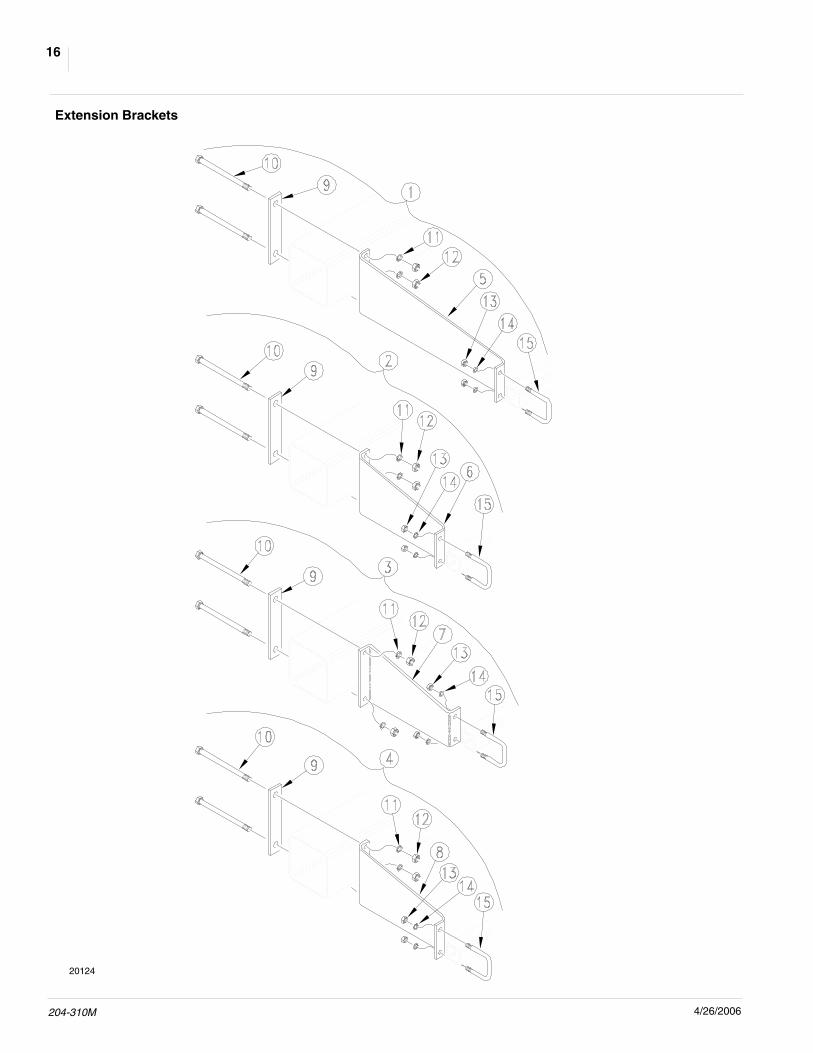
Extension Brackets
20124
4/26/2006 204-310M
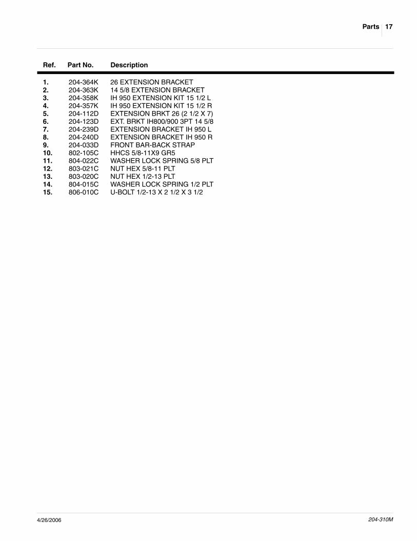
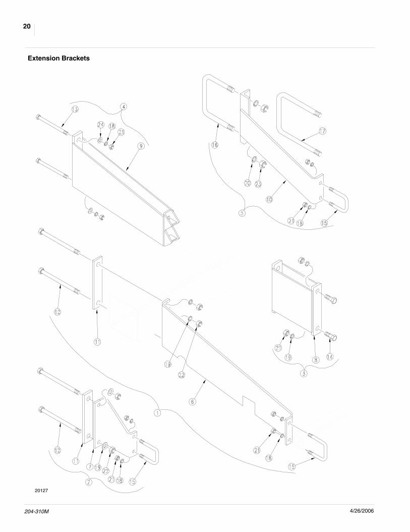
17Parts
1. 204-364K 26 EXTENSION BRACKET2. 204-363K 14 5/8 EXTENSION BRACKET3. 204-358K IH 950 EXTENSION KIT 15 1/2 L4. 204-357K IH 950 EXTENSION KIT 15 1/2 R5. 204-112D EXTENSION BRKT 26 (2 1/2 X 7)6. 204-123D EXT. BRKT IH800/900 3PT 14 5/87. 204-239D EXTENSION BRACKET IH 950 L8. 204-240D EXTENSION BRACKET IH 950 R9. 204-033D FRONT BAR-BACK STRAP10. 802-105C HHCS 5/8-11X9 GR511. 804-022C WASHER LOCK SPRING 5/8 PLT12. 803-021C NUT HEX 5/8-11 PLT13. 803-020C NUT HEX 1/2-13 PLT14. 804-015C WASHER LOCK SPRING 1/2 PLT15. 806-010C U-BOLT 1/2-13 X 2 1/2 X 3 1/2
Ref. Part No. Description

204-310M 4/26/2006
18
Extension Brackets
20125

4/26/2006 204-310M
19Parts
1. 204-351K COULTER EXT. KIT LEFT SHORT2. 204-352K COULTER EXT. KIT RIGHT SHORT3. 204-353K COULTER EXT. KIT LEFT LONG4. 204-354K COULTER EXT. KIT RIGHT LONG5. 890-543C COULTER EXTENSION LEFT6. 890-542C COULTER EXTENSION RIGHT7. 890-547C COULTER EXTENSION LEFT LONG8. 890-548C COULTER EXTENSION RIGHT LONG9. 204-236D COULTER EXT. TOP SUPPORT10. 802-164C HHCS 3/4-10X9 GR511. 804-023C WASHER LOCK SPRING 3/4 PLT12. 803-027C NUT HEX 3/4-10 PLT
Ref. Part No. Description
204-310M 4/26/2006
20
Extension Brackets
20127

4/26/2006 204-310M
21Parts
1. 204-365K 31 1/2 EXTENSION BRACKET2. 204-430S 9 1/2 EXTENSION BUNDLE3. 204-038K EXT. BRKT X 104. 204-039K EXT. BRKT 3 DIA. BAR5. 204-031K FRONT BAR REINFORCEMENT BRKT6. 204-082H EXTENSION BRACKET 31 9/16 JD7. 204-023D SPACER PLT 7 TO 2 1/2 SQ 9 1/28. 204-044H 10 EXT. BRKT9. 204-058H EXT. BRKT. DRY FERT 3 DIA10. 204-029H FRONT BAR BRKT 1811. 204-033D FRONT BAR-BACK STRAP12. 802-105C HHCS 5/8-11X9 GR513. 802-260C HHCS 1/2-13X7 GR514. 802-053C HHCS 5/8-11X1 3/4 GR515. 806-010C U-BOLT 1/2-13 X 2 1/2 X 3 1/216. 806-055C U-BOLT 3/4-10 X 7 1/32 X 6 1/217. 806-050C U-BOLT 3/4-10 X 7 X 8 1/218. 804-015C WASHER LOCK SPRING 1/2 PLT19. 804-022C WASHER LOCK SPRING 5/8 PLT20. 804-023C WASHER LOCK SPRING 3/4 PLT21. 803-020C NUT HEX 1/2-13 PLT22. 803-021C NUT HEX 5/8-11 PLT23. 803-027C NUT HEX 3/4-10 PLT24. 804-017C WASHER FLAT 1/2 USS PLT
Ref. Part No. Description

204-310M 4/26/2006
22
20120

4/26/2006 204-310M
23Appendix
Appendix
Torque Values Chart
in-tpi1 N · m2 ft-lb3 N · m ft-lb N · m ft-lb mm x pitch4 N · m ft-lb N · m ft-lb N · m ft-lb
1/4" - 20 7.4 5.6 11 8 16 12 M 5 X 0.8 4 3 6 5 9 7
1/4" - 28 8.5 6 13 10 18 14 M 6 X 1 7 5 11 8 15 11
5/16 - 18 15 11 24 17 33 25 M 8 X 1.25 17 12 26 19 36 27
5/16" - 24 17 13 26 19 37 27 M 8 X 1 18 13 28 21 39 29
3/8" - 16 27 20 42 31 59 44 M10 X 1.5 33 24 52 39 72 53
3/8" - 24 31 22 47 35 67 49 M10 X 0.75 39 29 61 45 85 62
7/16" - 14 43 32 67 49 95 70 M12 X 1.75 58 42 91 67 125 93
7/16" - 20 49 36 75 55 105 78 M12 X 1.5 60 44 95 70 130 97
1/2" - 13 66 49 105 76 145 105 M12 X 1 90 66 105 77 145 105
1/2" - 20 75 55 115 85 165 120 M14 X 2 92 68 145 105 200 150
9/16" - 12 95 70 150 110 210 155 M14 X 1.5 99 73 155 115 215 160
9/16" - 18 105 79 165 120 235 170 M16 X 2 145 105 225 165 315 230
5/8" - 11 130 97 205 150 285 210 M16 X 1.5 155 115 240 180 335 245
5/8" - 18 150 110 230 170 325 240 M18 X 2.5 195 145 310 230 405 300
3/4" - 10 235 170 360 265 510 375 M18 X 1.5 220 165 350 260 485 355
3/4" - 16 260 190 405 295 570 420 M20 X 2.5 280 205 440 325 610 450
7/8" - 9 225 165 585 430 820 605 M20 X 1.5 310 230 650 480 900 665
7/8" - 14 250 185 640 475 905 670 M24 X 3 480 355 760 560 1050 780
1" - 8 340 250 875 645 1230 910 M24 X 2 525 390 830 610 1150 845
1" - 12 370 275 955 705 1350 995 M30 X 3.5 960 705 1510 1120 2100 1550
1-1/8" - 7 480 355 1080 795 1750 1290 M30 X 2 1060 785 1680 1240 2320 1710
1 1/8" - 12 540 395 1210 890 1960 1440 M36 X 3.5 1730 1270 2650 1950 3660 2700
1 1/4" - 7 680 500 1520 1120 2460 1820 M36 X 2 1880 1380 2960 2190 4100 3220
1 1/4" - 12 750 555 1680 1240 2730 2010
1 3/8" - 6 890 655 1990 1470 3230 2380 1 in-tpi = nominal thread diameter in inches-threads per inch
1 3/8" - 12 1010 745 2270 1670 3680 2710 2 N· m = newton-meters
1 1/2" - 6 1180 870 2640 1950 4290 3160 3 ft-lb= foot pounds
1 1/2" - 12 1330 980 2970 2190 4820 3560 4 mm x pitch = nominal thread diameter in millimeters x thread pitch
Torque tolerance + 0%, -15% of torquing values. Unless otherwise specified use torque values listed above.
Grade 2 Grade 5 Grade 8
Bolt Head Identification
Bolt Size(Inches)
5.8 8.8 10.9
Class 5.8 Class 8.8 Class 10.9
Bolt Head Identification
Bolt Size(Metric)

204-310M 4/26/2006
24
WarrantyGreat Plains Manufacturing, Incorporated warrants to the original pur-chaser that this seeding equipment will be free from defects in materialand workmanship for a period of one year from the date of original pur-chase when used as intended and under normal service and conditionsfor personal use; 90 days for commercial or rental purposes. This War-ranty is limited to the replacement of any defective part by Great PlainsManufacturing, Incorporated and the installation by the dealer of anysuch replacement part. Great Plains reserves the right to inspect anyequipment or part which are claimed to have been defective in materialor workmanship.This Warranty does not apply to any part or product which in GreatPlains’ judgement shall have been misused or damaged by accident orlack of normal maintenance or care, or which has been repaired or al-tered in a way which adversely affects its performance or reliability, orwhich has been used for a purpose for which the product is not de-signed. This Warranty shall not apply if the product is towed at a speedin excess of 20 miles per hour.Claims under this Warranty must be made to the dealer which originallysold the product and all warranty adjustments must by made throughsuch dealer. Great Plains reserves the right to make changes in mate-rials or design of the product at any time without notice.This Warranty shall not be interpreted to render Great Plains liable fordamages of any kind, direct, consequential, or contingent, to property.Furthermore, Great Plains shall not be liable for damages resulting fromany cause beyond its reasonable control. This Warranty does not ex-tend to loss of crops, losses caused by harvest delays or any expenseor loss for labor, supplies, rental machinery or for any other reason.No other warranty of any kind whatsoever, express or implied, ismade with respect to this sale; and all implied warranties of mer-chantability and fitness for a particular purpose which exceedthe obligations set forth in this written warranty are hereby dis-claimed and excluded from this sale.This Warranty is not valid unless registered with Great Plains Manufac-turing, Incorporated within 10 days from the date of original purchase.

Great Plains Manufacturing, Inc.Corporate Office: P.O. Box 5060Salina, Kansas 67402-5060 USA