general tipper body guidelines - transport engineer
TRANSCRIPT

GENERAL TIPPER BODY
GUIDELINES
22 July 2016
Pag
e1 o
f 7
The following document has been prepared by TCS to provide basic guidance to vehicle modifiers when installing tipper bodies. This document also contains a list of non-compliance items that are commonly identified when inspecting second hand tipper bodies. These guidelines are supplied without prejudice and free of charge to assist modifiers. TCS will not be held liable for any problems that arise from sole reliance on, or misinterpretation of, these guidelines or from the introduction of new rules after the issue date of these guidelines. The following documents should be read in conjunction with these guidelines:
1. Vehicle Manufacturer (OEM) Body Building Guidelines (takes precedence over VSB-6 and TCS guidelines)
2. VSB-6 Sections J (Body Mounting), H (Chassis Frame), P (Tow Couplings) and G (Brakes). (VSB6 is the National Code of Practice for heavy vehicle modifications and takes precedence over TCS guidelines. At the time of printing, VSB6 could be accessed via the following link: http://www.infrastructure.gov.au/roads/vehicle_regulation/bulletin/vsb_06.aspx)
All modifications must be carried out by suitably qualified tradespeople in accordance with the relevant Australian Design Rules, Australian Standards and National Codes of Practice. Any uncertainties should be discussed with TCS prior to commencing the modification. These guidelines are not intended to be used as the sole instructional tool for vehicle modifiers; modifiers must be suitably qualified tradespeople who are experienced in modifying heavy vehicles. These guidelines do not provide all the necessary information to carry out a complete tipper body installation and must only be used as a supplementary quick reference guide. Tipper bodies should have a suitably strong, continuous sub-frame and with integrated tipping pivots and lifting ram cross-member. Joining the tipping pivots and ram cross-member into the sub-frame helps to spread the loads from these components through the chassis, which minimises concentrated chassis loading and reduces the likelihood of chassis failure. Diagrams in this document have been simplified to illustrate the topics being discussed and therefore may not show all components necessary for a complete sub-frame. Intermediate chassis cross members, suspension components, etc are also not shown. A simplified example of a sub-frame is provided below:
FIGURE 1: BASIC TIPPER SUB-FRAME

GENERAL TIPPER BODY
GUIDELINES
22 July 2016
Pag
e2 o
f 7
The leading edge of the sub-frame should provide a gradual reduction in stiffness to prevent chassis damage. Refer to TCS’ ‘Leading Edge of Sub-Frame’ guidelines for further information. Guide vanes must be installed to prevent the front of the body moving side-to-side. For steel tipper bodies, guide vanes are typically made from steel plate that is welded to the edges of the sub-frame and flared out at the top to guide the body into place as it is lowered. This type of arrangement can cause excessive wear on aluminium bodies, therefore rubber guides are often used instead. Substantial mounting plates need to be located in the vicinity of the ram cross member to provide restraint during tipping operations. These plates can be welded to the sub-frame but must be bolted to the chassis using ISO Grade 8.8 or equivalent (or stonger) bolts, hardened washers and self-locking nuts. Refer to TCS’ ‘Drilling Chassis Holes – Revision 1’ guidelines before drilling any holes in the chassis.
FIGURE 2: EXAMPLES OF A SUITABLE SUB-FRAME LEADING EDGE, MOUNTING PLATE AND GUIDE VANE
FIGURES 3A & 3B: ALTERNATE SUB-FRAME LEADING EDGE AND BODY GUIDES, FIGURE 3C: MOUNTING PLATE

GENERAL TIPPER BODY
GUIDELINES
22 July 2016
Pag
e3 o
f 7
The ram cross-member must be strong enough to support the tipping ram without deforming under all loading conditions throughout the life of the vehicle. Strengthening ribs are often required to provide adequate strength.
FIGURE 4: CROSS-SECTION VIEW OF RAM CROSS-MEMBER WITH STRENGTHENING RIBS
A cross-member is required at the rear end of the chassis. Wherever possible, the OEM cross-member should be retained and/or reinstalled if the rear of the chassis is shortened. A towbar mounted directly between the chassis rails is often a suitable substitute for a cross-member, but if the towbar is mounted to the outer webs of the chassis rails and the towbar cross-member is positioned below the chassis rails, a cross-member directly between the chassis rails should still be installed. The tipping pivot sleeves should be incorporated in the rear mounting plates to prevent them tearing out of the walls of the sub-frame. Tear-out is common if the pivot sleeves are welded into the walls of the sub-frame only as the sub-frame is often only half the thickness of the mounting plates. It is also recommended that reinforcing plates are installed on the inner faces of the sub-frame to provide additional support for the tipping pivot sleeves. The tipping pin/s must be suitably restrained so that they don’t slide out of the tipping pivot sleeves.
FIGURE 5: REAR MOUNTING PLATES, REAR CROSS-MEMBER, TIPPING PIVOT SLEEVES AND INNER REINFORCING PLATES

GENERAL TIPPER BODY
GUIDELINES
22 July 2016
Pag
e4 o
f 7
Tow Hitches If installing a tow hitch, please refer to TCS’ ‘Mounting Tow Hitches’ guidelines. Every towbar must have safety chain attachments fitted in accordance with ADR 62/xx even if the truck is fitted with an automatic pin coupling and will tow hinged drawbar trailers. There is a common misunderstanding that safety chain attachments on the towbar are not required if the truck will tow a dog trailer with a hinged drawbar, but this is incorrect. When towing a trailer with a hinged drawbar, actual safety chains don't have to be used but the towbar on the truck still has to have ADR compliant safety chain attachments fitted. Body Width The width of the overall vehicle (including tailgate hinges, tailgate levers and tarp rollers but not including lights, reflectors and mirrors) must not exceed 2500mm. Large fines can be issued for over-width vehicles. It is common for second hand bodies to be overwidth and the tailgate hinges often have to be moved inboard and/or the tailgate lever needs to be modified to rectify the issue. Reverse Lights Every vehicle must be fitted with reverse lights in accordance with the ADR applicable to the vehicle, see TCS’ ‘Reverse Lights’ guidelines for further guidance. If you are unsure of the ADRs applicable to your vehicle, the fail-safe way to ensure compliance is to install two white ADR-compliant reverse lights. Safety Props Every vehicle must be fitted a suitably strong safety prop, to support the unloaded body if someone is performing vehicle maintenance underneath it. The safety prop and underbody mating surface must be strong enough to prevent the prop from punching through the under side of the body. Hydraulic Burst Protection Every hydraulic tipping ram must be fitted with hydraulic burst protection that complies with AS1418; this prevents the raised body from dropping down suddenly in the event of a hydraulic failure.
FIGURES 6A: HYDRAULIC BURST PROTECTION CONNECTED TO RAM AND SAFETY PROP LOWERED
FIGURE 6B: SAFETY PROP RAISED BEFORE BODY IS LOWERED
GENERAL TIPPER BODY
GUIDELINES
22 July 2016
Pag
e5 o
f 7
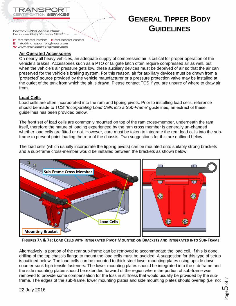
Air Operated Accessories On nearly all heavy vehicles, an adequate supply of compressed air is critical for proper operation of the vehicle’s brakes. Accessories such as a PTO or tailgate latch often require compressed air as well, but when the vehicle’s air pressure gets low, these auxiliary devices must be deprived of air so that the air can preserved for the vehicle’s braking system. For this reason, air for auxiliary devices must be drawn from a ‘protected’ source provided by the vehicle maunfacturer or a pressure protection valve may be installed at the outlet of the tank from which the air is drawn. Please contact TCS if you are unsure of where to draw air from. Load Cells Load cells are often incorporated into the ram and tipping pivots. Prior to installing load cells, reference should be made to TCS’ ‘Incorporating Load Cells into a Sub-Frame’ guidelines; an extract of these guidelines has been provided below. The front set of load cells are commonly mounted on top of the ram cross-member, underneath the ram itself, therefore the nature of loading experienced by the ram cross member is generally un-changed whether load cells are fitted or not. However, care must be taken to integrate the rear load cells into the sub-frame to prevent point loading the rear of the chassis. Two suggestions for this are outlined below. The load cells (which usually incorporate the tipping pivots) can be mounted onto suitably strong brackets and a sub-frame cross-member would be installed between the brackets as shown below:
FIGURES 7A & 7B: LOAD CELLS WITH INTEGRATED PIVOT MOUNTED ON BRACKETS AND INTEGRATED INTO SUB-FRAME
Alternatively, a portion of the rear sub-frame can be removed to accommodate the load cell. If this is done, drilling of the top chassis flange to mount the load cells must be avoided. A suggestion for this type of setup is outlined below. The load cells can be mounted to thick steel lower mounting plates using upside down counter-sunk high tensile fasteners. The lower mounting plates should be integrated into the sub-frame and the side mounting plates should be extended forward of the region where the portion of sub-frame was removed to provide some compensation for the loss in stiffness that would usually be provided by the sub-frame. The edges of the sub-frame, lower mounting plates and side mounting plates should overlap (i.e. not

GENERAL TIPPER BODY
GUIDELINES
22 July 2016
Pag
e6 o
f 7
be located in the same vertical plane) and should be tapered to provide gradual changes in stiffness. As always, if anything is unclear or the suggestions in this document will not work on a certain vehicle, TCS should be consulted before proceeding with the modification.
FIGURE 8: LOAD CELLS WITH MODIFIED SUB-FRAME, LOWER MOUNTING PLATES AND LARGER SIDE MOUNTING PLATES
FIGURE 9: TIPPER SUB-FRAME WITH INTEGRATED LOAD CELLS

GENERAL TIPPER BODY
GUIDELINES
22 July 2016
Pag
e7 o
f 7
FIGURE 10: LOAD CELLS WITH MODIFIED SUB-FRAME, LOWER MOUNTING PLATES AND LARGER SIDE MOUNTING PLATES