general specification for civil engineering works section ... · civil engineering works section 1...
TRANSCRIPT
2006 Edition
GENERAL SPECIFICATION FOR
CIVIL ENGINEERING WORKS
SECTION 1
GENERAL
1.1

2006 Edition
1.2
2006 Edition
SECTION 1
GENERAL
INTERPRETATION OF DOCUMENTS
Application of the 1.01 (1) The provisions contained in the Particular Specification and the General Specification Drawings shall prevail over the provisions contained in this General for Civil Engineering Specification for Civil Engineering Works (GS). Works
(2) The provisions contained in this General Specification for Civil Engineering Works shall prevail over the provisions contained in British Standards, British Standard Codes of Practice and similar standard documents stated in the Contract.
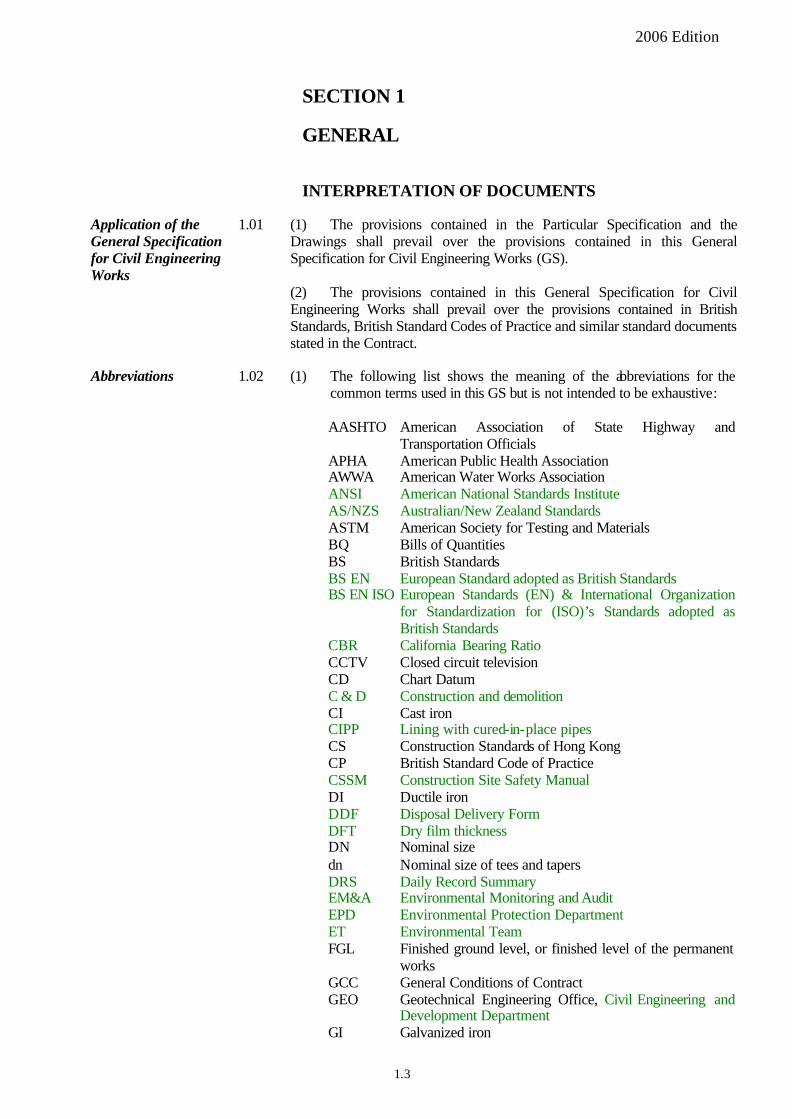
Abbreviations 1.02 (1) The following list shows the meaning of the abbreviations for the common terms used in this GS but is not intended to be exhaustive:
AASHTO American Association of State Highway and Transportation Officials
APHA American Public Health Association AWWA American Water Works Association ANSI American National Standards Institute AS/NZS Australian/New Zealand Standards ASTM American Society for Testing and Materials BQ Bills of Quantities BS British Standards BS EN European Standard adopted as British Standards BS EN ISO European Standards (EN) & International Organization
for Standardization for (ISO)’s Standards adopted as British Standards
CBR California Bearing Ratio CCTV Closed circuit television CD Chart Datum C & D Construction and demolition CI Cast iron CIPP Lining with cured-in-place pipes CS Construction Standards of Hong Kong CP British Standard Code of Practice CSSM Construction Site Safety Manual DI Ductile iron DDF Disposal Delivery Form DFT Dry film thickness DN Nominal size dn Nominal size of tees and tapers DRS Daily Record Summary EM&A Environmental Monitoring and Audit EPD Environmental Protection Department ET Environmental Team FGL Finished ground level, or finished level of the permanent
works GCC General Conditions of Contract GEO Geotechnical Engineering Office, Civil Engineering and
Development Department GI Galvanized iron
1.3

2006 Edition
GS General Specification for Civil Engineering Works HDPE High-density polyethylene HKSAR Hong Kong Special Administrative Region HOKLAS Hong Kong Laboratory Accreditation Scheme HSFG High strength friction grip ISO International Organisation for Standardization JIS Japanese Industrial Standards LPG Liquefied petroleum gas PC Portland cement PD Principal Datum PFA Pulverised-fuel ash PFAC Portland fly ash cement PFC Public Fill Committee ppm parts per million PS Particular Specification PTFE Polytetrafluoroethylene PVC Polyvinyl chloride QPME Quality Powered Mechanical Equipment RAP Reclaimed asphalt pavement SCC Special Conditions of Contract SIS Swedish Standards SMM Standard Method of Measurement for Civil Engineering
Works SRPC Sulphate resisting Portland cement TTS Trip-ticket system ULSD Ultra-low-sulphur diesel uPVC unplasticised polyvinyl chloride VHS Video Home System VOC Volatile Organic Compound WIS Water Industry Specification, Water Research Centre
(2) The following list shows the meaning of the abbreviations for the units used in this GS but is not intended to be exhaustive:
�C degrees Celsius dB decibels g gram g/mL gram(s) per millilitre g/m2 gram(s) per square metre ha hectare hr hour Hz hertz J joule kg kilogram kHz kilohertz kJ kilojoule km kilometre km/hr kilometre(s) per hour kN kiloNewton kPa kiloPascal kV kiloVolt kW kiloWatt L litre L/min litre(s) per minute L/s litre(s) per second m 1.4 metre
m2 square metre
2006 Edition
m3
m/s Mg Mg/m3
min
cubic metre metre(s) per second megagram megagram(s) per cubic metre minute
mL millilitre mm millimetre mm2
mm3
square millimetre cubic millimetre
mm/s MPa N N/mm N/m2
No.
millimetre(s) per second megaPascal Newton Newton(s) per millimetre Newton(s) per square metre number
NTU Pa.s r/min r/s s
nephelometric turbidity units Pascal(s) second revolution(s) per minute revolution(s) per second second
t tonne mm %
micrometer(micron) percentage
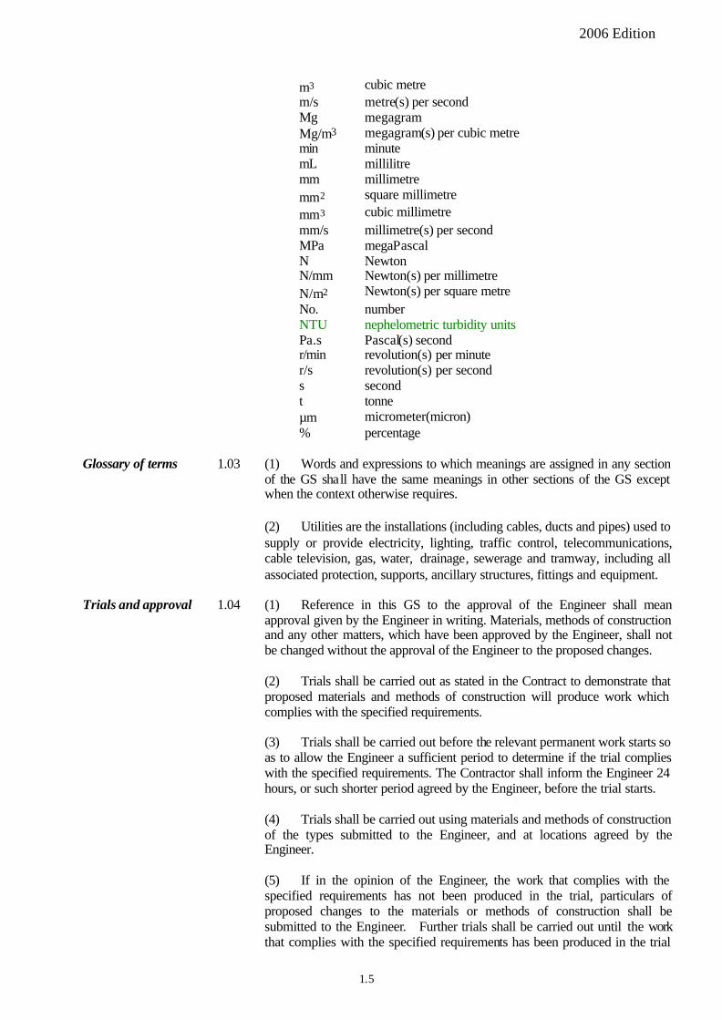
Glossary of terms 1.03 (1) Words and expressions to which meanings are assigned in any section of the GS shall have the same meanings in other sections of the GS except when the context otherwise requires.
(2) Utilities are the installations (including cables, ducts and pipes) used to supply or provide electricity, lighting, traffic control, telecommunications, cable television, gas, water, drainage, sewerage and tramway, including all associated protection, supports, ancillary structures, fittings and equipment.
Trials and approval 1.04 (1) Reference in this GS to the approval of the Engineer shall mean approval given by the Engineer in writing. Materials, methods of construction and any other matters, which have been approved by the Engineer, shall not be changed without the approval of the Engineer to the proposed changes.
(2) Trials shall be carried out as stated in the Contract to demonstrate that proposed materials and methods of construction will produce work which complies with the specified requirements.
(3) Trials shall be carried out before the relevant permanent work starts so as to allow the Engineer a sufficient period to determine if the trial complies with the specified requirements. The Contractor shall inform the Engineer 24 hours, or such shorter period agreed by the Engineer, before the trial starts.
(4) Trials shall be carried out using materials and methods of construction of the types submitted to the Engineer, and at locations agreed by the Engineer.
(5) If in the opinion of the Engineer, the work that complies with the specified requirements has not been produced in the trial, particulars of proposed changes to the materials or methods of construction shall be submitted to the Engineer. Further trials shall be carried out until the work that complies with the specified requirements has been produced in the trial
1.5
2006 Edition
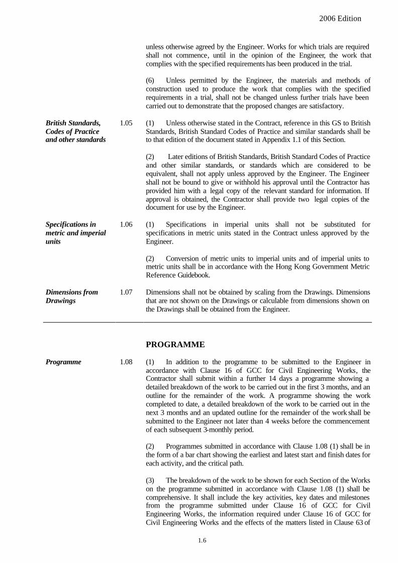
unless otherwise agreed by the Engineer. Works for which trials are required shall not commence, until in the opinion of the Engineer, the work that complies with the specified requirements has been produced in the trial.
(6) Unless permitted by the Engineer, the materials and methods of construction used to produce the work that complies with the specified requirements in a trial, shall not be changed unless further trials have been carried out to demonstrate that the proposed changes are satisfactory.
British Standards, Codes of Practice and other standards
1.05 (1) Unless otherwise stated in the Contract, reference in this GS to British Standards, British Standard Codes of Practice and similar standards shall be to that edition of the document stated in Appendix 1.1 of this Section.
(2) Later editions of British Standards, British Standard Codes of Practice and other similar standards, or standards which are considered to be equivalent, shall not apply unless approved by the Engineer. The Engineer shall not be bound to give or withhold his approval until the Contractor has provided him with a legal copy of the relevant standard for information. If approval is obtained, the Contractor shall provide two legal copies of the document for use by the Engineer.
Specifications in metric and imperial units
1.06 (1) Specifications in imperial units shall not be substituted for specifications in metric units stated in the Contract unless approved by the Engineer.
(2) Conversion of metric units to imperial units and of imperial units to metric units shall be in accordance with the Hong Kong Government Metric Reference Guidebook.
Dimensions from Drawings
1.07 Dimensions shall not be obtained by scaling from the Drawings. Dimensions that are not shown on the Drawings or calculable from dimensions shown on the Drawings shall be obtained from the Engineer.
PROGRAMME
Programme 1.08 (1) In addition to the programme to be submitted to the Engineer in accordance with Clause 16 of GCC for Civil Engineering Works, the Contractor shall submit within a further 14 days a programme showing a detailed breakdown of the work to be carried out in the first 3 months, and an outline for the remainder of the work. A programme showing the work completed to date, a detailed breakdown of the work to be carried out in the next 3 months and an updated outline for the remainder of the work shall be submitted to the Engineer not later than 4 weeks before the commencement of each subsequent 3-monthly period.
(2) Programmes submitted in accordance with Clause 1.08 (1) shall be in the form of a bar chart showing the earliest and latest start and finish dates for each activity, and the critical path.
(3) The breakdown of the work to be shown for each Section of the Works on the programme submitted in accordance with Clause 1.08 (1) shall be comprehensive. It shall include the key activities, key dates and milestones from the programme submitted under Clause 16 of GCC for Civil Engineering Works, the information required under Clause 16 of GCC for Civil Engineering Works and the effects of the matters listed in Clause 63 of
1.6
2006 Edition
GCC for Civil Engineering Works, together with the following:
(a) Work to be carried out, including testing and commissioning,
(b) Fabrication, delivery and installation of materials to be fabricated off the Site,
(c) Delivery of critical materials originating from outside the HKSARG,
(d) Activities for which the Employer or Engineer is responsible, including the issue of critical drawings and other information, provision of materials by the Employer, nomination and approval of Nominated Sub-contractors and consideration and approval of drawings and proposals, and
(e) Work to be carried out by Government departments, utility undertakings and other contractors.
(4) The Contractor shall be responsible for arranging, co-ordinating and agreeing with the utility undertakings a programme for their works. The Contractor shall make full allowance for time and provision of facilities for the utility undertakings in the preparation of his programmes.
CONTRACTOR'S SUPERINTENDENCE
Surveyor 1.09 (1) The Contractor shall employ on the Site a Surveyor for setting out the Works and for conducting slope and retaining wall record survey.
(2) The Surveyor shall possess a Diploma/Higher Certificate in Land Surveying from a Hong Kong technical institute/polytechnic or university, or equivalent qualification appropriate to the nature of the survey work required for the Contract, plus a minimum of 2 years of relevant experience in engineering surveying.
Foreman for concrete works
1.10 If structural concrete works are included in the Contract, the Contractor shall employ on the Site a Foreman who is suitably experienced in concrete works. The Foreman shall be on the Site at all times when concreting is in progress.
Supervision of piling works
1.11 (1) If piling works are included in the Contract, the Contractor shall employ on the Site a Construction Engineer who is required to visit the site at such time and frequency as necessary and shall be present to supervise inter alia, but not limited to, the following items:
(a) 100% check on the depth of excavation and the quality of retrieved material at the founding stratum, and
(b) 100% verification on the depth of the constructed piles by proof drilling (for large-diameter bored piles) including the retrieval of concrete and rock core samples for inspection and testing.
(2) The Contractor shall also employ on the Site a Construction Supervisor who shall be full time on site to supervise the piling works.
1.7
2006 Edition
Particulars of Agent and employees
(3) The Construction Engineer shall be a holder of a recognized degree in civil/structural/geotechnical engineering with 5 years of relevant experience. The Construction Supervisor shall either be a holder of a Higher Diploma/Higher Certificate in civil/structural/geotechnical engineering with 3 years of relevant experience, or a holder of a Diploma/Certificate in the same subjects with 5 years of relevant experience.
(4) The following particulars of the proposed Construction Engineer and Construction Supervisor for piling works shall be submitted to the Engineer for approval:
(a) Name;
(b) Copy of Hong Kong Identity Card;
(c) Details of qualifications, including copies of certificates;
(d) Details of previous experience.
1.12 (1) The proposed Agent as an employee of the Contactor shall hold a university degree acceptable to the Engineer and the HKIE academic requirements for Corporate Membership, or an equivalent qualification, in civil engineering or in a branch of civil engineering appropriate to the nature of the work included in the Contract, and shall have at least two years of relevant working experience. He must be bestowed with adequate authority to receive and carry out the directions and instructions from the Engineer and the Engineer’s Representative.
(2) The following particulars of the proposed Agent, Surveyor, Construction Engineer and Construction Supervisor for piling works and foreman for concrete works shall be submitted to the Engineer:
(a) Name,
(b) Copy of Hong Kong Identity Card,
(c) Details of qualifications, including copies of certificates, and
(d) Details of previous experience.
(3) The particulars of the proposed Agent, Surveyor, Construction Engineer and Construction Supervisor for piling works shall be submitted to the Engineer for approval and the particulars of the proposed foreman for concrete works shall be submitted to the Engineer for information.
(4) The particulars of the proposed Agent, Surveyor, Construction Engineer and Construction Supervisor for piling works shall be submitted within 7 days of commencement of the Works. The particulars of the proposed Foreman for concrete works shall be submitted within 7 days of his appointment
1.8
2006 Edition
SAFETY
Safety 1.13 (1) The Contractor shall keep on the Site a set of the current Construction Site Safety Manual (CSSM) issued by the Environment. Transport and Works Bureau (ETWB) of the Government of the Hong Kong Special Administrative Region (HKSAR). Attention of the Contractor is drawn to Appendix III of Chapter 3 of the CSSM about the need to keep one set of the legislation, regulations and/or codes pf practice on the Site.
(2) Safety precautions for working in sewers, drains and other confined spaces shall comply with the Factories and Industrial Undertakings (Confined Spaces) Regulations. The major provisions of these Regulations are contained in the current edition of the document “A Brief Guide to the Factories and Industrial Undertakings (Confined Spaces) Regulation” issued by the Labour Department of the Government of the HKSAR.
(3) Divers shall undergo regular medical checks and obtain certificates of fitness. Safety precautions for diving shall be in accordance with the current edition of the “Code of Practice: Safety and Health at Work for Industrial Diving” issued by the Labour Department of the Government of the HKSAR.
(4) Adequate safety equipment including, as appropriate, safety helmets, goggles, ear protectors, safety belts, safety equipment for working in sewers, drains and confined spaces, equipment for rescue from drowning, fire extinguishers, first aid equipment and other necessary safety equipment shall be available on the Site at all times.
(5) Safety equipment, scaffolds, working platforms, ladders and other means of access, and lighting, signing and guarding equipment shall be inspected and maintained regularly. Lights and signs shall be kept clean and easy to read. Equipment that are damaged, dirty, incorrectly positioned or not in working order shall be repaired or replaced immediately.
(6) Posters in both English and Chinese to draw attention to safety shall be obtained from the Labour Department and displayed at prominent locations around the Site including site offices, workshops and canteens.
WORK ON ROADS
Approval for temporary traffic arrangements and control
1.14 (1) In addition to any other requirements stated in the Contract, temporary traffic arrangements shall be in accordance with conditions and restrictions imposed by the Commissioner for Transport and the Commissioner of Police. Temporary lighting, signage, guarding and traffic control arrangements shall be in accordance with conditions and restrictions imposed by the Director of Highways. Traffic signs that are not prescribed by the Road Traffic Ordinance or its subsidiary legislation shall be in accordance with conditions and restrictions imposed by the Commissioner for Transport.
(2) The Contractor shall make all arrangements with and obtain the necessary approvals from the Commissioner for Transport, the Commissioner of Police, the Director of Highways and any other relevant authority for temporary traffic arrangements and control.
1.9
2006 Edition
Temporary traffic 1.15 (1) Temporary traffic diversions and pedestrian routes shall be provided arrangements and control
Particulars of temporary traffic arrangements and control
where work in roads or footways obstructs existing vehicular or pedestrian access. The relevant work shall not commence until the approved temporary traffic arrangements and control have been implemented.
(2) Temporary traffic arrangements and control for work in roads and footways shall comply with the requirements contained in the current edition of the document `Code of Practice for Lighting, Signing and Guarding of Road Works' issued by the Government of the HKSAR. A copy of the document shall be kept on the Site.
(3) Temporary traffic light signals shall be of a type approved by the Commissioner for Transport and shall comply with the requirements contained in the current editions of the documents `Type Approval Procedure for Portable Traffic Light Signals' and `Specification for Vehicle Actuated/Fixed Time Portable Traffic Signal Equipment' issued by the Government of the HKSAR.
(4) Temporary traffic signs, including posts, backing plates and faces, shall comply with the requirements for traffic signs contained in Section 12 except as stated in Clauses 1.15(5) and (6).
(5) The thickness of backing plates for temporary traffic signs that will be erected for less than 6 months may be reduced to 1.5 mm. The posts for signs may be constructed of timber or other material provided that in the opinion of the Engineer the traffic signs will be stable and safe.
(6) The Contractor shall design the arrangement of information on sign the faces for temporary traffic directional signs. The details of the background, borders and legends, including letters, numerals, characters and symbols, shall comply with the requirements of the Commissioner for Transport.
(7) The Contractor shall inspect and regularly maintain the temporary traffic arrangements and control, both day and night. He shall keep the traffic lights, lights and signs clean and easy to read, and shall immediately repair or replace the equipment that is damaged, dirty, incorrectly positioned or not in working order.
1.16 The following particulars of proposed temporary traffic arrangements and control shall be submitted to the Engineer for approval at least 7 days before the traffic arrangements and control are implemented:
(a) Details of traffic diversions and pedestrian routes,
(b) Details of lighting, signage, guarding and traffic control arrangements and equipment, and
(c) Any conditions or restrictions imposed by the Commissioner for Transport, the Commissioner of Police, the Director of Highways or any other relevant authority, including copies of applications, correspondence and approvals.
1.10
2006 Edition
Use of roads and footways
Work on roads and footways
1.17 (1) Roads, footways and cycle-tracks on the Site shall be maintained in a clean and passable condition and shall not be used to store materials or park constructional plant or other vehicles, other than those required for immediate use on the Works. The construction plant, materials and temporary works shall be placed with minimum interference with or disturbance to the use of any right of way by the public.
(2) Measures shall be taken to prevent excavated material, silt or debris from entering drainage systems in roads, footways and cycle -tracks. Entry of water to gullies shall not be obstructed.
(3) Surfaced roads on the Site and leading to the Site shall not be used by tracked vehicles unless protection against damage is provided.
(4) Construction plant and other vehicles leaving the Site shall be properly cleaned, loaded and covered in such a manner that excavated material, mud or debr is is not deposited on roads. Measures to be adopted shall include but not be limited to those specified under Clauses 25.15 and 25.26.
1.18 (1) Work on roads on the Site shall be carried out in sections such that the length of road occupied at any time does not exceed that stated in the Contract and the width of road occupied at any time does not exceed the width of one traffic lane unless permitted by the Engineer. Work on each section shall be completed and the road shall be reinstated and opened to traffic before work commences on the next section. Work on any section, including loading and unloading, shall be carried out in such a manner that traffic and utilities on the adjacent road and pedestrian access in the adjacent footway are adequately maintained.
(2) Before excavations are carried out on roads or footways, except in areas covered with paving blocks or tiles, the limits of the area to be reinstated shall be bounded by a continuous saw-cut groove. The groove shall be at least 6 mm wide and at least 50 mm deep. Cutting the groove and breaking out the road or footway shall be carried out in such a manner that the adjacent road or footway, including edges, is not damaged.
(3) Excavated material shall not be stored adjacent to excavations in roads or footways unless permitted by the Engineer.
(4) Vehicular access across excavations in roads shall be provided with steel covers. The covers shall be designed to BS 449: Part 2 and shall be capable of withstanding the full load of traffic permitted to use the road. The covers shall be secured in position and shall have anti-skid coating so that the skid resistance values of the covers measured in accordance with BS 3262 shall be not less than 45. Sufficient steel covers shall be kept on the Site adjacent to excavations in roads to permit vehicular access across the excavations in case of emergency. When installed, the steel covers shall be set to be flush with the road surface and shall not result in any noise nuisance by rocking under the action of traffic.
(5) Work on roads, footways and cycle-tracks shall be carefully planned to minimize the period of temporary excavation. If the Contractor is unable to proceed with the works after any excavation is carried out, he shall immediately backfill or temporarily reinstate the excavation.
1.11
2006 Edition
(6) In respect of works covered by the excavation permits issued by Highways Department and/or Lands Department as appropriate pursuant to the Land (Miscellaneous Provisions) Ordinance Cap 28 where the Contractor is the Nominated Permittee and the Employer is the Permittee, the Contractor shall comply with all conditions stated in the excavation permits.
Reinstatement of roads and footways
1.19 Temporary diversions, pedestrian access and lighting, signage, guarding and traffic control equipment shall be removed immediately they are no longer required. Roads, footways and other items affected by temporary traffic arrangements and control shall be reinstated to the condition existing before the work started or to such other condition as may be agreed or instructed by the Engineer.
CARE OF THE WORKS
Protection from water
1.20 (1) Unless otherwise permitted by the Engineer, all work shall be carried out, as near as may be practicable in the circumstances, in dry conditions, except where the work is required to be carried out in or with water or other fluids.
(2) Where necessary and as far as practicable, the Works including materials for use in the Works shall be kept free of water and protected from damage due to water. Temporary drainage, pumping systems or other effective measures approved by the Engineer shall be used. Silt and debris shall be intercepted with traps before water is discharged from the Site.
(3) The discharge points of the temporary drainage and pumping systems shall be approved by the Engineer. The Contractor shall make all arrangements with and obtain the necessary approvals and inspections from the relevant authorities for discharging water to drains, watercourses or the sea. The relevant work shall not start until the approved arrangements for disposal of the water have been implemented.
(4) Measures shall be taken to prevent flotation of new and existing structures.
Protection from weather
1.21 (1) Works shall not be carried out in weather conditions that may adversely affect the works unless protection by methods agreed by the Engineer is provided.
(2) Permanent works, including materials for permanent works, shall be protected by methods agreed by the Engineer from exposure to weather conditions that may adversely affect the work or materials.
Protection of works 1.22 Finished works shall be protected with methods agreed by the Engineer from damage that could arise from the execution of adjacent works. Works shall be carried out in such a manner that works carried out by others, including Government departments, utility undertakings and other contractors, is not damaged.
1.12
2006 Edition
DAMAGE AND INTERFERENCE
Damage and interference
1.23 (1) Works shall be carrie d out in such a manner that, as far as is reasonable and practicable, there is no damage to or interference with the following, other than such damage as is required to enable the execution of the Works:
(a) Watercourses;
(b) Utilities;
(c) Structures, roads including street furniture, or other property;
(d) Public or private vehicular or pedestrian accesses; and
(e) Trees, graves or burial urns.
(2) The Contractor shall inform the Engineer as soon as practicable of any item, utility or thing which is not stated in the Contract as requiring diversion, removal or relocation but which the Contractor considers as requiring diversion, removal or relocation to enable the Works to be executed. The Contractor shall not divert, remove or relocate any such item, utility or thing without the prior approval of the Engineer.
(3) Items which are damaged or interfered with as a result of the works being carried out and items which are diverted, removed or relocated to enable the works to be carried out, shall be reinstated to the same condition as was existing before the works started or to such other condition as may be agreed or instructed by the Engineer.
Watercourses and drainage systems
1.24 (1) The Contractor shall be responsible for maintaining all river and stream courses, drains and culverts within the Site until handover of the Site to the Employer. Rivers and stream courses shall be maintained in accordance the requirements of Clause 25.09. Maintenance of drains and culverts shall include, but not be confined to, the periodic clearance of debris, weed growth and other obstructions from the drains, culverts, manholes and flap valve chambers to the satisfaction of the Engineer. The Contractor shall ensure throughout the contract period that the flow capacity is not reduced and the quality of water is not worsened by execution of the Works.
(2) The Contractor shall be responsible for any temporary training or diversion of natural streams/rivers, drainage systems, nullahs and watercourses during execution of the Works and subsequent reinstatement. The Contractor shall submit to the Engineer particulars of the diversion and reinstatement proposals at least 21 days before the diversions are implemented. The Contractor shall programme construction of the Works to take account of all the necessary temporary diversions of the existing natural streams/ rivers, nullahs, watercourses and drains. The Contractor shall illustrate in his overall programme how the Works can be phased smoothly with the various necessary diversions.
(3) All diversions shall be of adequate capacity so as not to increase the risk of flooding to any area within, upstream or downstream of the Site either from heavy rainfall or high tides. The Contractor shall ensure that adequate provision is made for dealing with flood flows. Where the design of diversion
1.13
2006 Edition
proposals relies on contingency measures to quickly remove the installed temporary works from the drainage systems in order to provide sufficient flow capacity during adverse weather conditions, any such contingency measures and associated procedures shall be demonstrated to be ‘fail-safe’. The diversion shall be carefully planned to minimize disturbance caused to the natural beds of river/streams and riparian vegetation. The diversion shall be properly reinstated, including removal of any obstructions to flow, as soon as practicable after the works are completed, to the satisfaction of the Engineer.
(4) The natural bottom and existing flow in the river shall be preserved as much as possible to avoid disturbance to the river habitats. If temporary access track on riverbed is unavoidable, this shall be kept to the minimum width and length. Temporary river crossings shall be supported on stilts above the riverbed. Stockpiling of construction material, if necessary, shall be properly covered and located away from any natural stream/river. Measures shall be taken to prevent excavated material, silt or debris from being deposited or washed into existing streams and rivers, drainage systems, nullahs, watercourses, diversion channels or the sea. The measures to be adopted shall include but not be limited to those specified under Clauses 25.07, 25.08 and 25.09.
(5) Any sediment or debris that accumulates in any catchpit, manhole, sump, trap, drain, drainage channel or watercourse, whether temporary, existing or newly constructed, within the Site, shall be removed on a frequent basis, or as directed by the Engineer.
(6) Removal of existing vegetation alongside the riverbanks shall be avoided or minimized. When disturbance to vegetation is unavoidable, all disturbed areas shall be hydroseeded or planted with suitable vegetation to blend in with the natural environment upon completion of works.
Utilities 1.25 (1) The details of existing utilities are given for information only and the accuracy of the details is not guaranteed. The Contractor shall make his own enquiries and shall carefully excavate inspection pits to locate accurately the utilities indicated to him by the utility undertakings.
(2) Temporary supports and protection to utilities shall be provided by methods agreed by the Engineer. Permanent supports and protection shall be provided if instructed by the Engineer.
(3) The Contractor shall inform the Engineer and the utility undertakings without delay of the following:
(a) Damage to utilities,
(b) Leakage of utilities,
(c) Discovery of utilities not shown on the Drawings, and
(d) Diversion, removal, repositioning or re-erection of utilities, which is required to enable the execution of the Works.
(4) The Contractor shall take all steps necessary to enable the utility undertakings to proceed in accordance with the programme agreed between the Contractor and the utility undertakings under Clause 1.08(4). The Contractor shall maintain close liaison with the utility undertakings and shall inform the Engineer of any delays in works by the utility undertakings.
1.14
2006 Edition
(5) Records of existing utilities encountered shall be kept by the Contractor on the Site with a copy provided for the Engineer. The records shall be agreed by the Engineer and shall contain the following details:
(a) Location of utility,
(b) Date on which utility was encountered,
(c) Nature and size of utility,
(d) Condition of utility, and
(e) Temporary or permanent supports provided.
(6) Further to Clause 1.25(1), the Contractor shall submit for the Engineer's agreement, at least 14 days before any excavation by mechanical plant, a proposal for investigations to ascertain the nature, location and size of existing utilities by hand-dug inspection pits. Such investigations by inspection pits shall not relieve the Contractor of any of the duties, responsibilities, obligations or liabilities imposed upon him by any of the provisions of the Contract.
(7) Unless otherwise agreed by the Engineer in writing, the Contractor shall carry out investigations to locate utilities in accordance with the proposal referred to in Clause 1.25(6). The Contractor shall make his own enquiries with the utility undertakings as and when required and should any utility installations including cover tiles be exposed, the respective utility undertakings shall be contacted to determine if all their utilities have been located. Utility installations including cover tiles shall only be removed by the utility undertakings concerned.
(8) No excavation with mechanical plant shall commence until the nature, location and size of utilities that may be affected by the excavation have been ascertained and the setting-out details have been checked by the Engineer. The nature includes the type of utilities, protective uPVC/GI ducts or conduits, concrete surround, haunching and the like. The location includes the top/bottom levels, the coordinates of the center-lines of the utilities and the like.
(9) The Contractor shall provide adequate and experienced site personnel to control the operation of heavy mechanical plant in the proximity of utilities.
(10) The Contractor shall make arrangements to avoid any heavy mechanical plant or vehicles standing or passing over buried pipe-work in particular those at shallow depths with less than 1 metre overburden cover, especially when the road surface is removed. Unless agreed by the Engineer, the Contractor shall not stockpile any material immediately over or in the vicinity of any pipe-work.
(11) Pursuant to Clause 1.25(1), the Contractor shall carry out the Works in such a manner to avoid any damage or interference with any concrete blocks or structures attached to the utilities. The Contractor shall ensure that all cable draw-pits, valve-pits and the like are not covered up or removed as a result of his works and are accessible by utility undertakings at any time during the course of the Works for emergency repair.
1.15
2006 Edition
(12) Further to Clause 1.25(2), where utility installations are exposed, the Contractor shall liaise with the utility undertakers about the necessary protection for the exposed utilities and provide temporary protective measures and warning signs to prevent damaging the utility installations.
Structures, roads and other property
1.26 The Contractor shall immediately inform the Engineer of any damage to structures, roads or other property not required for the execution of the Works.
Access 1.27 Alternative access shall be provided if interference with existing public or private vehicular or pedestrian access is necessary to enable the execution of the Works. The arrangements for the alternative access shall be as agreed by the Engineer. The permanent access shall be reinstated as soon as practicable after the works are complete and the alternative access shall be removed as soon as practic able after it is no longer required.
RECORDS
Records of wage rates
1.28 The average, high and low wage rates for workers of each trade employed on the Site shall be entered on monthly wage return forms provided by the Engineer, and the completed forms returned to the Engineer within 4 days of the start of the succeeding month. For the purpose of completing the returns, actual trades shall be entered as the equivalent trades stated in Table 1.1.
Records of correspondence
1.29 Copies of correspondence relevant to execution of the Works (and not of a confidential nature) received from or despatched to Government departments, utility undertakings and other contractors employed by the Employer shall be submitted to the Engineer for information as soon as possible, but in any case not later than 7 days after receipt or despatch.
Records and reports 1.30 Reports and records, which are to be submitted to the Engineer, shall be in a format agreed by the Engineer. Reports and records shall be signed by the Contractor's agent or by another representative authorised by the Contractor.
1.16

2006 Edition
Table 1.1: Equivalent trades
Actual trade Equivalent trade
Office attendant Labourer (unskilled)
Watchman Labourer (unskilled)
Working ganger Ordinary worker in the trade in which he is employed or, if the trade is not listed, lorry driver
Survey labourer Concretor's labourer
Turf-layer Concretor's labourer
Bituminous material layer
Concretor's labourer
Shot-firer Plasterer
Lorry checker Labourer (unskilled)
Motor driver (car/van) Truck driver
Survey leveller Plumber
Welder Painter
Coxswain, barge Engineer
Truck driver
Dredger crew, barge crew
Diver's linesman
LIAISON WITH OTHERS
Liaison with others
1.31 (1) The Contractor shall make all necessary arrangements with and obtain the necessary approvals from Government departments, utility undertakings and other duly constituted authorities for carrying out the Works.
(2) The Contractor shall maintain close liaison with other contractors employed by the Employer, and utility undertakings or other authorities who are carrying out works on or adjacent to the Site. The Contractor shall ensure as far as possible that the progress of the Works is not adversely affected by the activities of such other contractors.
SITE CLEANLINESS
Site cleanliness 1.32 (1) The Site shall be maintained in a clean and tidy condition. Materials, including materials required for Temporary Works, shall be stored in an orderly manner. The measures to be taken shall include but not limited to the following:
1.17
2006 Edition
(a) Promptly remove all debris and litter on the site including those dumped into the site from outside by the public.
(b) Promptly remove debris and litter not within the site if the debris and litter are in connection with the Works or disposal of by the persons working on the site.
(c) Keep traffic cones, temporary traffic lights and signs clean, secure and in an orderly manner and refurbish, repaint and/or repair hoardings and/or steel barriers half yearly.
(d) Keep passageways clear and free of greasy dirt, waste and timber.
(2) The Contractor shall assign a designated person, with adequate knowledge, experience and authority, for the overall co-ordination, monitoring and overseeing of the performance of the site on cleanliness and control of mosquito breeding. Thereafter, the Contractor shall notify the Engineer of the name and contact telephone number of the assigned person and any subsequent change.
Prevention of mosquito breeding
1.33 (1) Measures shall be taken to prevent mosquito breeding on the Site. The measures to be taken shall include the following:
(a) Empty cans, oil drums, packings and other receptacles that may retain water shall be deposited at a central collection point and those not required for future use shall be removed from the Site regularly.
(b) Standing water shall be treated at least once every week with an oil which will prevent mosquito breeding.
(c) Construction plant and other items on the Site which may retain water shall be stored, covered or treated in such a manner that water will not be retained.
(d) Properly cover all water storage tanks, remove unnecessary stagnant water and disused containers, or use non-hazardous larvicide to prevent mosquito breeding as the last resort. The Contractor shall submit the characteristics, mixing formulation and method of application of the proposed larvicide to the Engineer for approval before its use; and
(e) Cut bamboo poles for scaffolding as near to the nodes of the poles as possible.
(2) Posters in both English and Chinese drawing attention to the dangers of permitting mosquito breeding shall be obtained from the Government of the HKSAR and displayed prominently on the Site.
Prevention of dust
1.34 Works shall be carried out in such a manner that avoidable dust is not generated. Measures to be adopted shall include but not be limited to those specified under Clause 25.15.
1.18
2006 Edition
MATERIALS AND EQUIPMENT
Materials and equipment provided by the Employer
1.35 (1) Materials and equipment which are to be provided by the Employer will be as stated in the Contract.
(2) Materials and equipment provided by the Employer shall be collected by the Contractor from the locations stated in Contract and delivered by the Contractor to the Site. The Contractor shall inspect the materials and equipment before taking receipt and shall immediately inform the Engineer of any shortage or damage.
(3) Materials or equipment provided by the Employer which are damaged after collection shall be repaired by the Contractor and submitted to the Engineer for approval. Materials or equipment, which are lost or which in the opinion of the Engineer are not capable of being or have not been repaired satisfactorily, shall be replaced by the Contractor.
(4) Crates and containers for materials or equipment provided by the Employer shall be disposed of by the Contractor.
(5) Equipment and materials provided by the Employer which are surplus to the requirements of the Works shall be returned to the locations stated in the Contract.
(6) The Contractor shall protect and maintain equipment provided by the Employer while it is on the Site and shall provide operatives, fuel and other consumables required to operate the equipment.
Materials 1.36 (1) Materials for inclusion in the permanent works shall be new or other material as stated in the Contract or approved by the Engineer.
(2) Certificates of tests by manufacturers that are submitted to the Engineer shall relate to the material delivered to the Site. Certified true copies of certificates may be submitted if the original certificates cannot be obtained from the manufacturer. A letter from the supplier stating that the certificates relate to the material delivered to the Site shall be submitted with the certificates.
(3) Samples of materials submitted to the Engineer for information or approval shall be kept on the Site and shall not be returned to the Contractor or used in the permanent works unless permitted by the Engineer.
TESTING
Quality assurance schemes
1.37 Tests stated in the Contract may be omitted or reduced in number as agreed by the Engineer if materials or articles delivered to the Site:
(a) Bear the stamp of the registered certification trade mark of the BS Institution, known as the BS Kitemark, or
(b) Are covered by a manufacturer's quality assurance scheme stated in the Contract or approved by the Engineer.
1.19
2006 Edition
Batches, samples and specimens
1.38 (1) A batch of material is a specified quantity of the material, which satisfies specified conditions such that it may be assumed that all of the material in the batch is of consistent type and quality. If one of the specified conditions is that the material is delivered to the Site at the same time, material delivered to the Site over a period not exceeding 7 days may be considered as part of the same batch if in the opinion of the Engineer there is sufficient evidence that the other specified conditions applying to the batch apply to all of the material delivered over the period.
(2) A sample is a specified amount, or a specified number of pieces or units, taken from a batch for testing, such that the result of tests on the sample can be taken as representing the quality of the batch as a whole.
(3) A specimen is a portion of a sample that is to be tested.
Samples for testing
1.39 (1) For the purpose of this Clause and Clauses 1.40, 1.42 and 1.49, “the Employer’s laboratories” shall mean:
(a) The laboratories of the Laboratories (PWL), and
Employer such as Public Works
(b) The laboratories currently appointed by the Employer.
(2) Samples for laboratory tests or test locations for insitu tests shall be randomly selected by the Engineer. In addition, the Engineer shall be free to select samples he suspects to be defective. The test locations for insitu tests so selected and, if applicable, the area/extent of Works covered by the tests, shall be traceable by means of either a referenced co-ordinates system or a location plan with defined test positions and levels.
(3) Samples shall be representative and of sufficient size to enable all specified tests to be performed.
(4) Samples shall be taken on Site under close supervision of the Engineer or by the Employer’s laboratories having no direct commercial relationship with the Contractor or material supplier, and shall be clearly, indelibly and individually marked for identification.
(5) Once selected and taken, samples stored on Site before delivery to the place of testing shall remain in the charge of the Engineer or the Employer’s laboratories, who/which shall be given adequate facilities (including sample store room) to keep samples securely under lock and key inaccessible to unauthorised persons at all times.
(a) Samples shall be protected, handled and stored in such a manner that they are not damaged nor contaminated such that the properties of the sample do not change. The method of storage shall comply with the requirements of the relevant test methods.
(b) Where insitu concreting works are to be carried out, the Contractor shall, at the discretion of the Engineer, provide sufficient number of steel container rooms (or the like) and curing tanks for storage and curing test cubes to the satisfaction of the Engineer in accordance with Clause 1.49(4).
1.20
2006 Edition
(6) Samples shall be collected and delivered by the Contractor under close supervision of the Engineer or by the Employer’s laboratories to the specified place of testing. During transportation from Site to the specified place of testing, all samples shall be securely locked in containers or suitably modified vehicle compartments unless otherwise approved by the Engineer, with keys kept by the Engineer or the Employer’s laboratories.
(7) The transfer of samples from one place/person to another shall be clearly documented and checked. The person receiving the samples shall acknowledge the receipt and confirm the identification of the samples. A record showing:
(a) When, where and by whom the samples are taken, and
(b) Persons who have handled the samples before and during delivery to the place of testing,
shall be prepared and maintained by the Engineer (with assistance of the Employer’s laboratories when necessary) so that the samples delivered from Site to the specified place of testing are traceable.
(8) For those tests where supervisory attendance is essential for providing guidance on Site or for obtaining test data, details of such supervisory site staff present shall be recorded in relevant data sheets and/or sample submission forms to enhance data integrity.
(9) For the purpose of stock control to preclude the swapping of materials under test and where applicable the unauthorised use of materials before receipt of test results, the Contractor shall:
(a) Clearly identify all batches of materials arriving on the Site (the identification marks so designed shall contain information which can reveal the identity of the batch for each type of material such as the Contract number, type of material, batch number and other information as required by the Engineer);
(b) Keep stockpiles and stock items from which samples have been taken pending test results separated from other materials by means of labels denoting “Stock under Test” or similar agreed by the Engineer;
(c) Establish and maintain a record system showing identification marks, testing status of all materials (under test or approved for use or rejected or re-test or omitted for testing, etc.), key dates (e.g. date of testing) and locations of storage; and
(d) In connection with the above, submit a proposal for a stock management system on Site peculiar to the Contract to prevent unauthorised or uncontrolled use of materials for approval by the Engineer at the commencement of the Contract and subsequent supervision by the Engineer.
(10) Samples on which non-destructive tests have been carried out shall be collected from the place of testing after testing and delivered to the Site or other location instructed by the Engineer.
1.21
2006 Edition
(11) Samples which have been tested may be incorporated in the permanent works provided that:
(a) The sample complies with the specified requirements,
(b) The sample is not damaged, and
(c) Such use as permitted under Clause 1.36(3).
(12) Additional samples shall be provided for testing if in the opinion of the Engineer:
(a) Material previously tested no longer complies with the specified requirements, or
(b) Material has been handled or stored in such a manner that it is no longer represented by previously tested samples.
Testing 1.40 (1) Unless otherwise stated in the Contract, insitu tests and laboratory tests shall be carried out by the Employer’s laboratories if the aforesaid tests can be undertaken by the Employer’s laboratories. Testing shall not be carrie d out in other laboratories unless permitted by the Engineer. If testing is permitted to be carried out by the Contractor:
(a) Independent laboratories with no affiliation as a legal entity to the Contractor or its sub-contractors shall be used,
(b) Laboratories accredited by HOKLAS for the relevant tests shall be used, if available, in which case results shall be issued on HOKLAS endorsed test reports,
(c) Particulars of the laboratory proposed by the Contractor shall be submitted to the Engineer for approval, and
(d) Tests shall be adequately supervised by the Engineer.
(2) The Contractor shall be entitled to attend testing associated with the Works that is carried out in the Employer’s laboratories, and to inspect relevant records.
(3) Unless otherwise stated in the Contract, equipment, apparatus and materials for insitu tests and laboratory tests carried out by the Contractor shall be provided by the Contractor. The equipment and apparatus shall be maintained by the Contractor and shall be calibrated before testing starts and at regular intervals agreed by the Engineer. Calibration requirements and source of calibration applicable to all laboratory equipment shall follow those recommended in the HOKLAS Supplementary Criteria No. 2 “All Test Categories - Equipment Calibration”. The equipment, apparatus and materials for insitu tests shall be removed by the Contractor as soon as practicable after testing is complete.
(4) Workability tests of fresh concrete shall be carried out by skilled personnel of the Contractor.
Compliance of a batch
1.41 (1) Unless otherwise stated in the Contract, the results of tests on samples or specimens shall be considered as representing the whole of the batch from which the sample was taken.
1.22
2006 Edition
(2) A batch shall be considered as complying with the specified requirements for the material if the results of specified tests for specified properties comply with the specified requirements for the properties.
(3) If additional tests are permitted and separate compliance criteria for the additional tests are not stated in the Contract, the Engineer shall determine if the batch complies with the specified requirements for the material on the basis of the results of all tests, including the additional tests, for every property.
Raw records of tests and test reports
1.42 (1) Raw records of insitu tests and laboratory compliance tests carried out by the Contractor (excluding the laboratories engaged by the Contractor) shall be submitted to the Engineer immediately after the te sts, or at such other time stated in the Contract, with a copy of the whole set of records kept by the Contractor on the Site.
(2) For all insitu tests and laboratory compliance tests, a test report shall be submitted to the Engineer in sealed envelope within 7 days, or such other time stated in the Contract, after completion of each test. The report shall contain the following details:
(a) Material or part of the work tested,
(b) Location and area/extent of the batch from which the samples were taken or location and area/extent of the part of the work,
(c) Place of testing,
(d) Date and time of each test,
(e) Weather conditions in the case of insitu tests,
(f) Technical personnel supervising or carrying out the tests,
(g) Size and description of samples and specimens,
(h) Method of sampling,
(i) Properties tested,
(j) Method of testing,
(k) Readings and measurements taken during the tests,
(l) Test results, including any calculations and graphs, and
(m) Other details stated in the Contract.
(3) All test reports compiled by the laboratories (which refer to the Employer’s laboratories and those engaged by the Contractor) shall be delivered directly to the Engineer in a sealed envelope without routing through the Contractor.
(4) Copies of test records carried out through the Employer’s laboratories will be given to the Contractor on request.
1.23
2006 Edition
WORKMANSHIP AND TOLERANCES
Workmanship 1.43 Workmanship shall comply with best trade practice and with relevant British Standard.
Tolerances 1.44 (1) Tolerances stated in the Contract shall be measured perpendicular to the specified lines unless otherwise stated in the Contract.
(2) If adjacent parts of the Works are subject to different dimensional tolerances then the most critical tolerance shall apply to all such works that relate to each other in respect of dimension, line and level.
SITE ESTABLISHMENT
Use of the Site 1.45 (1) The Site shall not be used by the Contractor for any purpose other than for executing the Works or carrying out other works associated with the Works and approved by the Engineer.
(2) Concrete batching and mixing plant erected on the Site shall not be used to provide concrete for work outside the Site.
(3) Bituminous materials batching and mixing plant erected on the Site shall not be used to provide bituminous materials for works outside the Site.
(4) Rock crushing plant shall not be erected on the Site unless stated in the Contract.
(5) The location and size of stockpiles of materials, including excavated material, within the Site shall be as agreed by the Engineer. Stockpiles shall be maintained in a stable condition.
(6) Entry to and exit from the Site shall be only gained at the locations stated in the Contract or agreed by the Engineer.
Submission of particulars
1.46 (1) The following particulars shall be submitted to the Engineer for approval not more than 14 days of the commencement of the Works:
(a) Drawings showing the layout within the Site of the Engineer's and Contractor's accommodation, project signboards, access roads and major facilities required early in the Contract,
(b) Drawings showing the layout and the construction details of the Engineer's accommodation, and
(c) Drawings showing the details to be included on project signboards.
(2) Drawings showing the location of stores, storage areas, concrete and bituminous materials batching and mixing plants, rock crushing plants and other major facilities not required early in the Contract shall be submitted to the Engineer for approval as early as possible, but in any case not later than 28 days before such facilities are constructed on the Site.
1.24
2006 Edition
Survey of the Site 1.47
Fences and signs 1.48 on the Site
The Engineer's 1.49 Site accommodation
A survey of the Site to establish the precise boundaries of the Site and the levels within the Site will be carried out by the Engineer after site clearance, and before other works start in each area to be surveyed. The Contractor shall carry out the survey jointly with the Engineer and agree the result as soon as practicable after completion of site clearance, before commencing other works in the area surveyed.
(1) Hoardings, fences, gates and signs on the Site shall be maintained in a clean, presentable, stable and secure condition. Logos, pictures and text shall be legible and not visually obstructed at all times.
(2) Project signboards stated in the Contract shall be erected not more than 4 weeks, or such other period agreed by the Engineer, after the date for commencement of the Works. Other advertising signs shall not be erected on the Site unless permitted by the Engineer.
(3) The Engineer’s permission shall be obtained before hoardings, fences, gates or signs are removed. Hoardings, fences, gates and signs that are to be left in position after completion of the Works shall be repaired and repainted as instructed by the Engineer.
(4) All components of site hoardings and signboards shall be metallic and not be made of timber. Bolts and nuts shall be used to join the panels of hoardings and signboards unless otherwise approved by the Engineer.
(1) For new accommodation to be erected, preference shall be given to the used prefabricated units that are in good working and serviceable conditions. The accommodation to be provided on the Site for the Engineer shall be ready for occupation, including connection of all utilities, not more than 8 weeks after the date of approval by the Engineer of the proposed location, layout, construction details and measures against all foreseeable hazards such as flooding, landslides, lightning, etc.
(2) The accommodation shall be maintained in a clean, stable and secure condition and shall be cleaned at least daily. The services of a full-time attendant shall be provided for the Engineer.
(3) Equipment provided for the use of the Engineer or persons authorised by the Engineer shall be maintained in a clean and serviceable condition and all consumables shall be replenished when required. Equipment shall, wherever practicable , have Grade 1 Energy Efficiency Labels, or Energy Labels for equipment operated only under the “Recognition Type” labelling system, under the Hong Kong Energy Efficiency Labelling Scheme. They shall include features to facilitate the minimization of waste and consumables. Office equipment must be able to handle use of paper on both sides. Consumables shall be made from recycled material and shall be recyclable wherever practicable. Measuring and testing equipment shall be calibrated before it is used and at regular intervals agreed by the Engineer. Calibration requirements as well as source of calibration applicable to all laboratory equipment shall follow those recommended in the HOKLAS Supplementary Criteria No. 2 “All Test Categories - Equipment Calibration”. Survey equipment shall be maintained by the service agent and shall be calibrated by an approved laboratory at regular intervals agreed by the Engineer. Equivalent replacements shall be provided for equipment that is out of service.
1.25
2006 Edition
The Contractor's Site accommodation
1.50
Site utilities and access
1.51
Transport for the Engineer
1.52
(4) Where insitu concreting works are to be carried out, steel container rooms and curing tanks shall be provided on the Site, at the discretion of the Engineer, according to the requirements stated in Appendix 1.2 and Appendix 1.3 respectively. In this connection, concreting works shall not commence until curing tanks and container rooms (or the like) are completed and accepted by the Engineer or unless otherwise approved by the Engineer. Where directed by the Engineer, Employer’s laboratories shall be given sole access and use of the steel container rooms and curing tanks together with all the equipment provided under the Contract.
(5) The Engineer’s permission shall be obtained before accommodation or equipment is removed. Portable accommodation shall be moved at the times instructed by the Engineer. Accommodation or equipment which is to be left in position or become the property of the Employer after completion of the Works shall be repaired, repainted and serviced as instructed by the Engineer.
The Contractor's offices, sheds, stores, mess rooms, latrines and other accommodation on the Site shall be maintained in a clean, stable and secure condition. Living accommodation shall not be provided on the Site unless stated in the Contract or approved by the Engineer.
(1) Temporary water, electricity, telephone, sewerage and drainage facilities shall be provided for the Engineer's accommodation and for the Contractor's use in carrying out the Works. The Contractor shall make all arrangements with and obtain the necessary approvals from the relevant authorities for the facilities.
(2) Access roads and parking areas shall be provided within the Site as required and shall be maintained in a clean, passable and stable condition with regular suppression of dust as required in Section 25.
(1) A new motor vehicle as transport for the Engineer will not always be required. However, where a used motor vehicle will suffice, it shall not be more than 2 years old when first brought to Site. Transport for the Engineer shall be provided from the date of commencement of the Works unless otherwise permitted or instructed by the Engineer.
(2) The transport shall be for the exclusive use of the Engineer in connection with supervision of Works and persons authorised by the Engineer and shall be available at all times during normal working hours and at other times when the Contractor is working or when instructed by the Engineer. The transport shall not be used by the Contractor or other persons who are not authorised by the Engineer.
(3) The transport shall be maintained in a clean and serviceable condition and shall be serviced regularly. Fuel, oil and other consumables, taxes, licenses, insurances, toll charges and parking and mooring fees shall be provided by the Contractor. The engines of land transport shall be propelled by petrol, liquefied petroleum gas (LPG), electric ity, hybrid of petrol-electric ity, or any other non-fossil fuels as approved by the Engineer. Land transport shall be covered by fully comprehensive insurance, which includes passenger liability and which allows the vehicle to be driven by any driver.
(4) A competent English-speaking driver shall be appointed and shall be available to drive transport when required by the Engineer.
1.26
2006 Edition
Clearance of the Site
1.53
(5) Marine transport shall be equipped and manned in accordance with the statutory requirements of the Marine Department and licensed under the Merchant Shipping (Launches and Ferry Vessels) Regulations Chapter 281. A qualified English-speaking coxswain shall be appointed and shall be available when the marine transport is required by the Engineer.
(6) Records of journeys shall be kept in logbooks provided by the Engineer. Records shall include details of the times and purpose of journeys with appropriate odometer readings and distances travelled. The person using the transport or authorising the journey shall sign against the logbook entries. Logbooks shall be presented for inspection when required by the Engineer and all completed logbooks shall be handed over to the Engineer.
(7) Equivalent transport shall be provided when transport is unavailable for any reason.
(8) The transport shall be provided until the end of the Maintenance Period or such earlier date instructed by the Engineer.
Temporary Works that are not to remain on the Site after completion of the Works shall be removed on completion of the Works or at other times instructed by the Engineer. The Site shall be cleared and reinstated to the lines and levels and to the condition existing before the Works started except as otherwise stated in the Contract.
Meetings 1.54
MEETINGS
The Contractor's agent shall attend, and shall arrange for the representatives of Sub-contractors, Government departments, transport companies, utility undertakings and other Contractors to attend, meetings when required by the Engineer. The Contractor shall inform the Engineer in 48 hours (or such a shorter period as agreed by the Engineer) before conducting meetings with Government departments, transport companies, utility undertakings and/or other Contractors and shall give the Engineer an opportunity to attend such meetings.
Photographs 1.55
PHOTOGRAPHS
Colour photographs, including underwater photographs, showing the progress of the Works and the quality of the materials and workmanship shall be taken at the times and at locations instructed by the Engineer. Photographs shall be captioned with the time, date and location. Selected prints shall be authenticated by the Contractor and the Engineer by signing the back of the prints and the following shall be provided for the Engineer:
(a) A negative of each photograph,
(b) One 3R print of each photograph,
(c) Albums to store the photographs, and
(d) Framed 8R prints of photographs selected by the Engineer.
1.27
2006 Edition
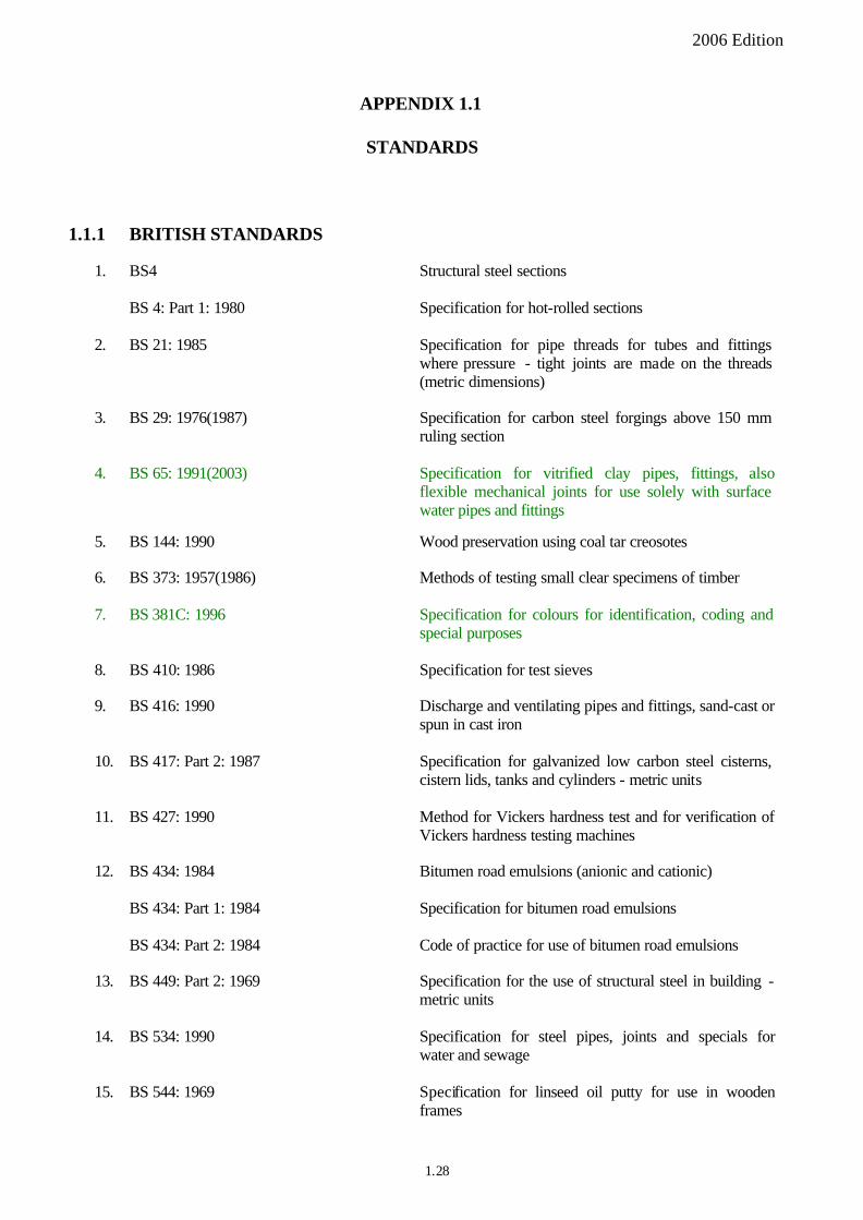
APPENDIX 1.1
STANDARDS
1.1.1 BRITISH STANDARDS
1. BS4 Structural steel sections
BS 4: Part 1: 1980 Specification for hot-rolled sections
2. BS 21: 1985 Specification for pipe threads for tubes and fittings where pressure - tight joints are made on the threads (metric dimensions)
3. BS 29: 1976(1987) Specification for carbon steel forgings above 150 mm ruling section
4. BS 65: 1991(2003) Specification for vitrified clay pipes, fittings, also flexible mechanical joints for use solely with surface water pipes and fittings
5. BS 144: 1990 Wood preservation using coal tar creosotes
6. BS 373: 1957(1986) Methods of testing small clear specimens of timber
7. BS 381C: 1996 Specification for colours for identification, coding and special purposes
8. BS 410: 1986 Specification for test sieves
9. BS 416: 1990 Discharge and ventilating pipes and fittings, sand-cast or spun in cast iron
10. BS 417: Part 2: 1987 Specification for galvanized low carbon steel cisterns, cistern lids, tanks and cylinders - metric units
11. BS 427: 1990 Method for Vickers hardness test and for verification of Vickers hardness testing machines
12. BS 434: 1984 Bitumen road emulsions (anionic and cationic)
BS 434: Part 1: 1984 Specification for bitumen road emulsions
BS 434: Part 2: 1984 Code of practice for use of bitumen road emulsions
13. BS 449: Part 2: 1969 Specification for the use of structural steel in building metric units
14. BS 534: 1990 Specification for steel pipes, joints and specials for water and sewage
15. BS 544: 1969 Specification for linseed oil putty for use in wooden frames
1.28
BS 812: Part 118: 1988 Method for determination of sulphate content
BS 812: Part 121: 1989
Method for determination of soundness
2006 Edition
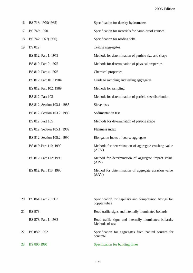
16. BS 718: 1979(1985) Specification for density hydrometers
17. BS 743: 1970 Specification for materials for damp-proof courses
18. BS 747: 1977(1986) Specification for roofing felts
19. BS 812 Testing aggregates
BS 812: Part 1: 1975 Methods for determination of particle size and shape
BS 812: Part 2: 1975 Methods for determination of physical properties
BS 812: Part 4: 1976 Chemical properties
BS 812: Part 101: 1984 Guide to sampling and testing aggregates
BS 812: Part 102: 1989 Methods for sampling
BS 812: Part 103 Methods for determination of particle size distribution
BS 812: Section 103.1: 1985 Sieve tests
BS 812: Section 103.2: 1989 Sedimentation test
BS 812: Part 105 Methods for determination of particle shape
BS 812: Section 105.1: 1989 Flakiness index
BS 812: Section 105.2: 1990 Elongation index of coarse aggregate
BS 812: Part 110: 1990 Methods for determination of aggregate crushing value (ACV)
BS 812: Part 112: 1990 Method for determination of aggregate impact value (AIV)
BS 812: Part 113: 1990 Method for determination of aggregate abrasion value (AAV)
20. BS 864: Part 2: 1983 Specification for capillary and compression fittings for copper tubes
21. BS 873 Road traffic signs and internally illuminated bollards
BS 873: Part 1: 1983 Road traffic signs and internally illuminated bollards. Methods of test
22. BS 882: 1992 Specification for aggregates from natural sources for concrete
23. BS 890:1995 Specification for building limes
1.29
26. BS 970: Part 1: 1996 General inspection and testing procedures and specific requirements for carbon, carbon manganese, alloy and stainless steels
28. BS 1006: 1990 Methods of test for colour fastness of textiles and leather
32. BS 1052: 1980(1999) Specification for mild steel wire for general engineering purposes
2006 Edition
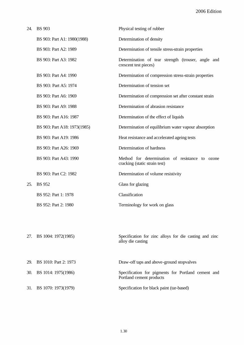
24. BS 903 Physical testing of rubber
BS 903: Part A1: 1980(1988) Determination of density
BS 903: Part A2: 1989 Determination of tensile stress-strain properties
BS 903: Part A3: 1982 Determination of tear strength (trouser, angle and crescent test pieces)
BS 903: Part A4: 1990 Determination of compression stress-strain properties
BS 903: Part A5: 1974 Determination of tension set
BS 903: Part A6: 1969 Determination of compression set after constant strain
BS 903: Part A9: 1988 Determination of abrasion resistance
BS 903: Part A16: 1987 Determination of the effect of liquids
BS 903: Part A18: 1973(1985) Determination of equilibrium water vapour absorption
BS 903: Part A19: 1986 Heat resistance and accelerated ageing tests
BS 903: Part A26: 1969 Determination of hardness
BS 903: Part A43: 1990 Method for determination of resistance to ozone cracking (static strain test)
BS 903: Part C2: 1982 Determination of volume resistivity
25. BS 952 Glass for glazing
BS 952: Part 1: 1978 Classification
BS 952: Part 2: 1980 Terminology for work on glass
27. BS 1004: 1972(1985) Specification for zinc alloys for die casting and zinc alloy die casting
29. BS 1010: Part 2: 1973 Draw-off taps and above-ground stopvalves
30. BS 1014: 1975(1986) Specification for pigments for Portland cement and Portland cement products
31. BS 1070: 1973(1979) Specification for black paint (tar-based)
1.30
BS 1191: Part 1: 1973 (1994)
Excluding premixed lightweight plasters
44. BS 1377: 1990 (as modified in
accordance with Geospec 3, entitled “Model Specification for Soil Testing”, except for Clause 7.39(1) where the year of edition remains to be 1975)
2006 Edition
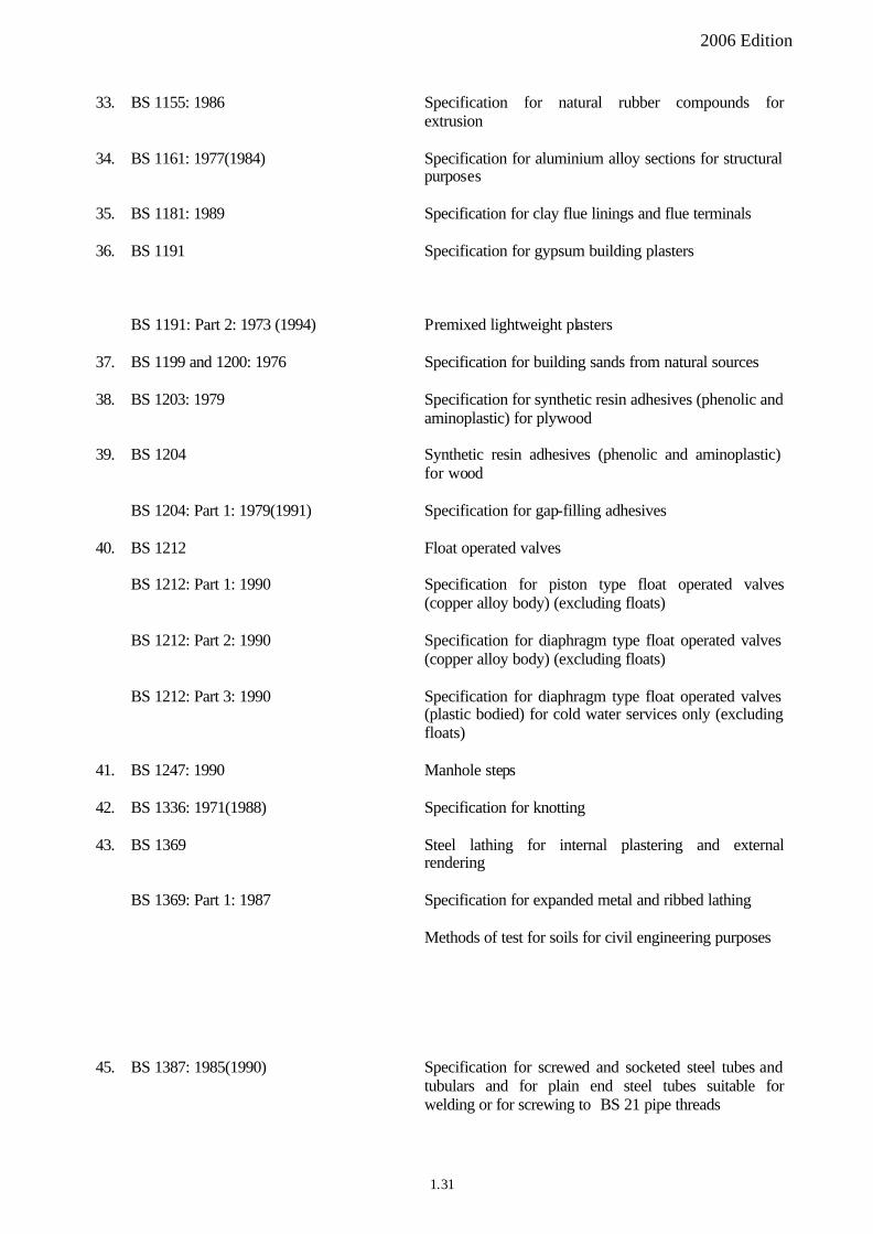
33. BS 1155: 1986 Specification for natural rubber compounds for extrusion
34. BS 1161: 1977(1984) Specification for aluminium alloy sections for structural purposes
35. BS 1181: 1989 Specification for clay flue linings and flue terminals
36. BS 1191 Specification for gypsum building plasters
BS 1191: Part 2: 1973 (1994) Premixed lightweight plasters
37. BS 1199 and 1200: 1976 Specification for building sands from natural sources
38. BS 1203: 1979 Specification for synthetic resin adhesives (phenolic and aminoplastic) for plywood
39. BS 1204 Synthetic resin adhesives (phenolic and aminoplastic) for wood
BS 1204: Part 1: 1979(1991) Specification for gap-filling adhesives
40. BS 1212 Float operated valves
BS 1212: Part 1: 1990 Specification for piston type float operated valves (copper alloy body) (excluding floats)
BS 1212: Part 2: 1990 Specification for diaphragm type float operated valves (copper alloy body) (excluding floats)
BS 1212: Part 3: 1990 Specification for diaphragm type float operated valves (plastic bodied) for cold water services only (excluding floats)
41. BS 1247: 1990 Manhole steps
42. BS 1336: 1971(1988) Specification for knotting
43. BS 1369 Steel lathing for internal plastering and external rendering
BS 1369: Part 1: 1987 Specification for expanded metal and ribbed lathing
Methods of test for soils for civil engineering purposes
45. BS 1387: 1985(1990) Specification for screwed and socketed steel tubes and tubulars and for plain end steel tubes suitable for welding or for screwing to BS 21 pipe threads
1.31
2006 Edition
46. BS 1400: 1985 Specification for copper alloy ingots and copper alloy and high conductivity copper castings
47. BS 1449: Part 1: 1983 Specification for carbon and carbon-manganese plate, sheet and strip
BS 1449: Part 2: 1983 Specification for stainless and heat-resisting steel plate, sheet and strip
48. BS 1452: 1990 Specification for flake graphite cast iron
49. BS 1473: 1972 Specification for wrought aluminium and aluminium alloys for general engineering purposes - rivet, bolt and screw stock
50. BS 1494: Part 2: 1967 Sundry fixings
51. BS 1610 Materials testing machines and force verification equipment
BS 1610: Part 1: 1992 Specification for the grading of the forces applied by materials testing machines when used in the compression mode
52. BS 1722: Part 1: 1986 Specification for chain link fences
53. BS 1740: Part 1: 1971(1990) Specification for wrought steel pipe fittings (screwed BS 21 R-series thread)
54. BS 1924: 1990 Stabilized materials for civil engineering purposes
55. BS 2000 Methods of test for petroleum and its products
56. BS 2015: 1965(1985) Glossary of paint terms
57. BS 2451: 1963(1988) Specification for chilled iron shot and grit
58. BS 2456: 1990 Specification for floats (plastics) for float operated valves for cold water services
59. BS 2494: 1990 Specification for elastomeric seals for joints in pipework and pipelines
60. BS 2499 Hot-applied joint sealant systems for concrete pavements
BS 2499: Part 1: 1993 Specification for joint sealants
BS 2499: Part 2: 1992 Code of practice for the application and use of joint sealants
BS 2499: Part 3: 1993 Hot-applied joint sealant systems for concrete pavements. Methods of test
61. BS 2523: 1966(1983) Specification for lead-based priming paints
1.32
BS 2782: Part 6: Method 631A: 1993
2006 Edition
62. BS 2569: Part 1: 1964 (1988)
63. BS 2600
BS 2600: Part 1: 1983
BS 2600: Part 2: 1973
64. BS 2633: 1987
65. BS 2648: 1955
66. BS 2760: 1973
67. BS 2782
BS 2782: Part 3: Methods 320A to 320F: 1976
BS 2782: Part 3: Method 365A: 1976(1989)
BS 2782: Part 3: Method 365D: 1978(1983)
BS 2782: Part 4: Methods 430A to 430D: 1983
BS 2782: Part 10: Method 1005: 1977 (U.K. national version of European Standard EN 63: 1977 with identical text) BS 2782: Part 6: Method 630A: 1994
68. BS 2789: 1985
69. BS 2846: Part 3: 1975(1985)
Protection of iron and steel by aluminium and zinc against atmospheric corrosion
Radiographic examination of fusion welded butt joints in steel
Methods for steel 2 mm up to and including 50 mm thick
Methods for steel over 50 mm up to and including 200 mm thick
Specification for Class I arc welding of ferritic steel pipework for carrying fluids
Performance requirements for electrically-heated laboratory drying ovens
Specification for pitch-impregnated fibre pipes and fittings for below and above ground drainage
Methods of testing plastics
Tensile strength, elongation and elastic modulus
Determination of softness number of flexible plastics materials
Determination of hardness of plastics and ebonite by the ball indentation method
Determination of water absorption at 23�C. Determination of water absorption at 23�C with allowance for water-soluble matter. Determination of boiling water absorption. Determination of boiling water absorption with allowance for water-soluble matter.
Methods of testing plastics. Glass reinforced plastics. Determination of flexural properties. Three point method.
Methods of testing plastics. Dimensional properties. Determination of thickness by mechanical scanning of flexible sheet
Methods of testing plastics. Dimensional properties. Determination of gravimetric thickness and yield of flexible sheet
Specification for spheroidal graphite or nodular graphite
cast iron
Determination of a statistical tolerance interval
1.33
2006 Edition
BS 2846: Part 4: 1976(1985) Techniques of estimation and tests relating to means and variances
70. BS 2869: Part 2: 1988 Specification for fuel oil for agricultural and industrial engines and burners (classes A2, C1, C2, D, E, F, G and H)
71. BS 2871: Part 1: 1971 Copper tubes for water, gas and sanitation
72. BS 2874: 1986 Specification for copper and copper alloy rods and sections (other than forging stock)
73. BS 2910: 1986 Methods for radiographic examination of fusion welded circumferential butt joints in steel pipes
74. BS 2989: 1982 Specification for continuously hot-dip zinc coated and iron-zinc alloy coated steel: wide strip, sheet/plate and slit wide strip
75. BS 3049: 1976 Specification. Pedestrian guard rails (metal)
76. BS 3100: 1976(1984) Specification for steel castings for general engineering purposes
77. BS 3148: 1980 Methods of test for water for making concrete (including notes on the suitability of the water)
78. BS 3262: Part 3: 1989 Specification for application of material to road surfaces
79. BS 3382: Part 1 & 2: 1961 Cadmium on steel components. Zinc on steel components
80. BS 3410: 1961 Specification for metal washers for general engineering purposes
81. BS 3416: 1991 with AMD 7288 Specification for bitumen-based coatings for cold application, suitable for use in contact with potable water
82. BS 3468: 1986 Specification for austenitic cast iron
83. BS 3505: 1986 Specification for unplasticized polyvinyl chloride (PVC-U) pressure pipes for cold potable water
84. BS 3506: 1969 Specification for unplasticized PVC pipe for industrial uses
85. BS 3600: 1976(1988) Specification for dimensions and masses per unit length of welded and seamless steel pipes and tubes for pressure purposes
86. BS 3601: 1987 Specification for carbon steel pipes and tubes with specified room temperature properties for pressure purposes
1.34
87. BS 3661 Methods for the determination of the colour fastness of textiles
91. BS 3892: Part 1: 1982 Specification for pulverized fuel ash for use as a
cementitious component in structural concrete
BS 3900: Part A2: 1983 Examination and preparation of samples for testing
BS 3900: Part A6: 1996 Paints and varnishes. Determination of flow time by use of flow cups
BS 3900: Part C2: 1994 Paints and varnishes. Surface drying test. Ballotini method
BS 3900: Part C3: 1990 Paints and varnishes. Determination of through dry state and through dry time. Method of test
BS 3900: Part C5: 1992 Determination of film thickness
BS 3900: Part C6: 1983 Determination of fineness of grind
BS 3900: Part D4: 1974 (2000) Comparison of contrast ratio (hiding power) of paints of the same type and colour
BS 3900: Part D5: 1980 Measurement of specular gloss of non metallic paint films at 200, 600 and 850
BS 3900: Part E1: 1995 Bend test (cylindrical mandrel)
BS 3900: Part E2: 1992 Scratch test
BS 3900: Part F8: 1976 Paints and varnishes. Determination of resistance to
humid atmospheres containing sulphur dioxide
BS 3900: Part G6: 1989 (2000) Assessment of resistance to fungal growth
93. BS 3921: 1985 Specification for clay bricks
2006 Edition
88. BS 3690: Part 1: 1989 Specification for bitumens for roads and other paved areas
BS 3690: Part 2: 1989 Specification for bitumens for industrial purposes
89. BS 3692: 1967 Specification for ISO metric precision hexagon bolts, screws and nuts. Metric units
90. BS 3698: 1964(1979) Specification for calcium plumbate priming paints
-
92. BS 3900 Methods of test for paints
-
--
-
BS 3900: Part E10: 1979(1989) Mechanical tests on paint films - Pull-off test for adhesion
94. BS 3923: Part 1: 1986 Methods for manual examination of fusion welds in ferritic steels
1.35
98. BS 4019: 1993 Rotary core drilling equipment
99. BS 4027: 1996 Specification for Sulphate resisting Portland Cement
100. BS 4043: 1989 Recommendations for transplanting root balled trees
101. BS 4052: 1987 Method for determination of thickness loss of textile floor coverings under dynamic loading
102. BS 4098: 1975 (1996) Method for the determination of thickness, compression and recovery characteristics of textile floor coverings
103. BS 4072: 1987 Wood preservation by means of copper/chromium/ arsenic compositions
104. BS 4102:1998 Specification for steel wire for general fencing purposes
107. BS 4190: 2001 Specification for ISO metric black hexagon bolts, screws and nuts
109. BS 4223: 1989 (1996) Methods for determination of constructional details of
textile floor coverings with yarn pile
2006 Edition
BS 3923: Part 2: 1972
95. BS 3981: 1976(1985)
96. BS 3987: 1974
97. BS 3998: 1989
105. BS 4147: 1980(1987)
106. BS 4168: Part 1: 1981
108. BS 4211: 1987
110. BS 4232: 1967
111. BS 4254: 1983
112. BS 4320: 1968
113. BS 4345: 1968(1986)
114. BS 4346
Automatic examination of fusion welded butt joints in ferritic steels
Specification. Iron oxide pigments for paints
Specification for anodic oxide coatings on wrought aluminium for external architectural applications
Recommendations for tree work
-
-
Specification for bitumen-based hot-applied coating materials for protecting iron and steel, including suitable primers where required
Specification for hexagon socket head cap screws
Specification for ladders for permanent access to chimneys, other high structures, silos and bins
Specification for surface finish of blast-cleaned steel for painting
Specification for two-part polysulphide-based sealants
Specification for metal washers for general engineering purposes. Metric series
Specification for slotted angles
Joints and fittings for use with unplasticized PVC pressure pipes
1.36
115. BS 4360: 1986 Specification for weldable steels
118. BS 4428: 1991 Code of Practice for general landscape operations
(excluding hard surfaces)
120. BS 4449: 1997(2001) Specification for carbon steel bars for the reinforcement
of concrete
123. BS 4483: 1998 Specification for steel fabric for the reinforcement of concrete
2006 Edition
BS 4346: Part 1: 1969 Injection moulded unplasticized PVC fittings for solvent welding for use with pressure pipes, including potable water supply
BS 4346: Part 2: 1970 Mechanical joints and fittings, principally of unplasticized PVC
BS 4346: Part 3: 1982 Specification for solvent cement
116. BS 4393: 1969(1985) Specification for tin or tin-lead coated copper wire
117. BS 4395 Specification for high strength friction grip bolts and associated nuts and washers for structural engineering
BS 4395: Part 1: 1969 General grade
BS 4395: Part 2: 1969 Higher grade bolts and nuts and general grade washers
BS 4395: Part 3: 1973 Higher grade bolts (waisted shank), nuts and general grade washers
119. BS 4447: 1973(1990) Specification for the performance of prestressing anchorage for post-tensioned construction
121. BS 4466: 1989 Specification for scheduling, dimensioning, bending and cutting of steel reinforcement for concrete
122. BS 4482: 1985 Specification for cold reduced steel wire for the reinforcement of concrete
124. BS 4486: 1980 Specification for hot rolled and hot rolled and processed high tensile alloy steel bars for the prestressing of concrete
125. BS 4504: Section 3.1: 1989 Circular flanges for pipes, valves and fittings (PN designated) - Specification for steel flanges
126. BS 4514: 1983 Specification for unplasticized PVC soil and ventilating pipes, fittings and accessories
127. BS 4515: 1984 Specification for welding of steel pipelines on land and offshore
128. BS 4550: 1Part 1: 1978 Methods of testing cement – Sampling
1.37
138. BS 4660: 2000 Specification for thermoplastics ancillary fittings of
nominal sizes 110 and 160 for below ground gravity drainage and sewerage
141. BS 4682: Part 1: 1971 Determination of extension under mechanical action
142. BS 4682: Part 3: 1981 (1996) Determination of dimensional changes after exposure to heat
143. BS 4756: 1971(1983) Specification for ready mixed aluminium priming paints for woodwork
144. BS 4772: 1988 Ductile piping and fittings
145. BS 4790: 1987 (1996) Method for determination of the effects of a small source of ignition on textile floor coverings (hot metal nut method)
2006 Edition
129. BS 4551: 1980 Methods of testing mortars, screeds and plasters
130. BS 4568 Specification for steel conduit and fittings with metric threads of ISO form electrical installations
BS 4568: Part 1: 1970 Steel conduit, bends and couplers
BS 4568: Part 2: 1970(1988) Fittings and components
131. BS 4570: 1985 Specification for fusion welding of steel castings
132. BS 4576: Part 1: 1989 unplasticized polyvinyl chloride (PVC-U) rainwater goods and assessories - Half-round gutters and pipes of circular cross-section
133. BS 4604 Specification for the use of high strength friction grip bolts in structural steelwork.
134. BS 4604: Part 1: 1970 Use of High Strength Friction Grip Bolts in Structural Steelwork. Metric Series Part 1: General Grade
BS 4604: Part 2: 1970 Use of High Strength Friction Grip Bolts in Structural Steelwork. Metric Series Part 2: Higher Grade (Parallel Shank)
135. BS 4620: 1970(1988) Specification for rivets for general engineering purposes
136. BS 4622: 1970(1983) Specification for grey iron pipes and fittings
137. BS 4652: 1971(1979) Specification for metallic zinc-rich priming paint (organic media)
139. BS 4662: 1970(1989) Specification for boxes for the enclosure of electrical accessories
140. BS 4677: 1984 Specification for arc welding of austenitic stainless steel pipework for carrying fluids
1.38
146. BS 4797: 1978 Method of test for textiles determination of resistance to certain insect pests
162. BS 5252F: 1976(2004) Framework for colour co ordination for building
purpose: colour matching fan
2006 Edition
–
147. BS 4848 Specification for hot-rolled structural steel sections
BS 4848: Part 2: 1975 Hollow sections
BS 4848: Part 4: 1972(1986) Equal and unequal angles
BS 4848: Part 5: 1980 Bulb flats
148. BS 4865: Part 1: 1989 Specification for non-metallic flat gaskets (including gaskets for flanges to BS 4772)
149. BS 4870: Part 1: 1981 Specification for approval testing of welding procedures - Fusion welding of steel
150. BS 4872: Part 1: 1982 Specification for approval testing of welders when welding procedure approval is not required - Fusion welding of steel
151. BS 4873: 1986 Specification for aluminium alloy windows
152. BS 4921: 1988 Specification for sheradized coatings on iron or steel
153. BS 4933: 1973 Specification for ISO metric black cup and countersunk head bolts and screws with hexagon nuts
154. BS 4942: 1981 Short link chain for lifting purposes
155. BS 5075: Part 1: 1982 Specification for accelerating admixtures, retarding admixtures and water reducing admixtures
BS 5075: Part 3: 1985 Specification for superplasticizing admixtures
156. BS 5135: 1984 Specification for arc welding or carbon and carbon manganese steels
157. BS 5150: 1990 Specification for cast iron gate valves
158. BS 5154: 1989 Specification for copper alloy globe, globe stop and check, check and gate valves
159. BS 5163: 1986 Specification for predominantly key-operated cast iron gate valves for waterworks purposes
160. BS 5212: 1990 Cold applied joint sealant systems for concrete pavements
161. BS 5215: 1986 Specification for one-part gun grade polysulphide-based sealants
-
163. BS 5255: 1989 Specification for thermoplastics waste pipe and fittings
1.39
164. BS 5262:1991 Code of practice for external renderings
168. BS 5325: 2001 Installation of textile floor coverings. Code of practice
169. BS 5385 1:1995 Wall and floor tiling. Code of practice for the design and installation of internal ceramic and natural stone wall tiling and mosaics in normal conditions
170. BS 5385: Part 2: 1991 Code of Practice for the design and installation of external ceramic wall tiling and mosaics
174. BS 5492:1990 Code of practice for internal plastering
180. BS 5808: 1991 (1996) Specification for underlays for textile floor coverings
2006 Edition
165. BS 5268: Part 2: 1988 Structural use of timber - Code of practice for permissible stress design, materials and workmanship
166. BS 5284: 1976 Methods. Sampling and testing mastic asphalt and pitchmastic used in building
167. BS 5289: 1976(1983) Code of practice. Visual inspection of fusion welded joints
-
171. BS 5395: Part 1: 1977(1984) Code of practice for the design of straight stairs
172. BS 5400 Steel, concrete and composite bridges
BS 5400: Part 2: 1978 Specification for loads
BS 5400: Part 4: 1990 Code of practice for design of concrete bridges
BS 5400: Part 6: 1980 Specification for materials and workmanship, steel
BS 5400: Part 9: 1983 Bridge bearings
BS 5400: Section 9.2: 1983 Specification for materials, manufacture and installation of bridge bearings
173. BS 5481: 1977(1989) Specification for unplasticized PVC pipe and fittings for gravity sewers
175. BS 5493: 1977 Code of practice for protective coating of iron and steel structures against corrosion
176. BS 5572: 1994 Code of practice for sanitary pipework
177. BS 5573: 1978 Code of practice for safety precautions in the construction of large diameter boreholes for piling and other purposes
178. BS 5589: 1989 Code of practice for preservation of timber
179. BS 5756: 1980(1985) Specification for tropical hardwoods graded for structural use
1.40
181. BS 5835:Part 1:1980. Compactability test for graded aggregates.
182. BS 5837: 1991 Guide for trees in relation to construction
BS 5911: Part 114: 1992 Specification for porous pipes
2006 Edition
183. BS 5896: 1980 Specification for high tensile steel wire and strand for the prestressing of concrete
184. BS 5911 Precast concrete pipes, fittings and ancillary products
BS 5911: Part 2: 1982 Specification for inspection chambers and street gullies
BS 5911: Part 3: 1982 Specification for pipes and fittings with ogee joints
BS 5911: Part 100: 1988 Specification for unreinforced and reinforced pipes and fittings with flexible joints
BS 5911: Part 200: 1989 Specification for unreinforced and reinforced manholes and soakaways of circular cross section
185. BS 5930: 1981 Code of practice for site investigations
186. BS 5931: 1980 Code of practice for machine laid in situ edge details for paved areas
187. BS 5950: Part 2: 1985 Specification for materials, fabrication and erection: hot rolled sections
188. BS 5980: 1980 Specification for adhesive for use with ceramic tiles and mosaics
189. BS 5996: 1980 Methods for ultrasonic testing and specifying quality grades of ferritic steel plate
190. BS 6072: 1981(1986) Method for magnetic particle flaw detection
191. BS 6089: 1981 Guide to assessment of concrete strength in existing structures
192. BS 6105: 1981 Specification for corrosion-resistant stainless steel fasteners
193. BS 6150: 1982 Code of practice for painting of buildings
194. BS 6262: 1982 Code of practice for glazing for buildings
195. BS 6323: 1982(1990) Specification for seamless and welded steel tubes for automobile, mechanical and general engineering purposes
BS 6323: Part 1: 1982(1990) General requirements
BS 6323: Part 3: 1982(1990) Specific requirements for hot finished seamless steel tubes
1.41
BS 6431: Part 10: 1984 (1996) Method for determination of dimensions and surface quality
BS 6431: Part 11: 1983 (1996) Method for determination of water absorption
BS 6431: Part 13: 1986 (1996) Method for determination of scratch hardness of surface according to Mohs
BS 6431: Part 14: 1983 (1996) Method for determination of resistance to deep abrasion. Unglazed tiles
BS 6431: Part 15: 1983 (1996) Method for determination of linear thermal expansion
BS 6431: Part 17: 1983 (1996) Method for determination of crazing resistance. Glazed tiles
2006 Edition
BS 6323: Part 8: 1982(1990) Specific requirements stainless steel tubes
for longitudinally welded
196. BS 6349: Part 1: 1984 Code of practice for maritime structures criteria
- General
197. BS 6362: 1990 Specification for stainless steel tubes suitable for screwing in accordance with BS 21 `Pipe threads for tubes and fittings where pressure-tight joints are made on the threads'
198. BS 6405: 1984 Specification for non-calibrated short link steel chain (Grade 30) for general engineering purposes: class 1 and 2
199. BS 6431 Ceramic floor and wall tiles
BS 6431: Part 1: 1983 Specification for classification and marking, including definitions and characteristics
BS 6431: Part 2: 1984 Specification for extruded ceramic tiles with a low water absorption (E < 3%). Group A1
BS 6431: Part 3 Extruded ceramic tiles with a water absorption of 3% < E < 6%. Group A11a
BS 6431: Part 3: Section 3.1: 1986 Specification for general products
BS 6431: Part 3: Section 3.2: 1986 Specification for products (terre cuite, cotto, baldosin catalan)
BS 6431: Part 4 Extruded ceramic tiles with a water absorption of 6% < E < 10%. Group A11b
BS 6431: Part 4: Section 4.1: 1986 Specification for general products
BS 6431: Part 4: Section 4.2: 1986 Specification for specific products (terre cuite, cotto, baldosin catalan)
BS 6431: Part 12: 1983 (1996) Method for determination of modulus of rupture
1.42
BS 6431: Part 18: 1983 (1996) Method for determination of chemical resistance. Unglazed tiles
BS 6431: Part 19: 1984 (1996) Method for determination of chemical resistance. Glazed tiles
BS 6431: Part 20: 1984 (1996) Method for determination of resistance to surface abrasion. Glazed tiles
208. BS 6717:2001 Precast, unreinforced concrete paving blocks. Requirements and test methods
2006 Edition
200. BS 6443: 1984 Method for penetrant flaw detection
201. BS 6463 Quicklime, hydrated lime and natural calcium carbonate
BS 6463: Part 1: 1984 Methods of sampling
BS 6463: Part 2: 1984 Methods of chemical analysis
BS 6463: Part 4: 1987 Methods of test for physical properties of hydrated lime and lime putty
202. BS 6510: 1984 Specification for steel windows, sills, window boards and doors
203. BS 6558: 1985 Optical fibres and cables
204. BS 6566 Plywood
205. BS 6577: 1985 Specification for mastic asphalt for building (natural rock asphalt aggregate)
206. BS 6657: 1986 Guide for prevention of inadvertent initiation of electro-explosive devices by radio-frequency radiation
207. BS 6681: 1986 Specification for malleable cast iron
209. BS 6700: 1987 Specification for design, installation, testing and maintenance of services supplying water for domestic use within buildings and their cartilages
210. BS 6744:2001 Stainless steel bars for the reinforcement of and use in concrete. Requirements and test methods
211. BS 6779: Part 1: 1998 Highway parapets for bridges and other structures. Specification for vehicle containment parapets of metal construction
212. BS 6920 Suitability of non-metallic products for use in contact with water intended for human consumption with regard to their effect on the quality of the water
BS 6920: Part 1: 1990 Specification
BS 6920: Part 2 Methods of test
1.43
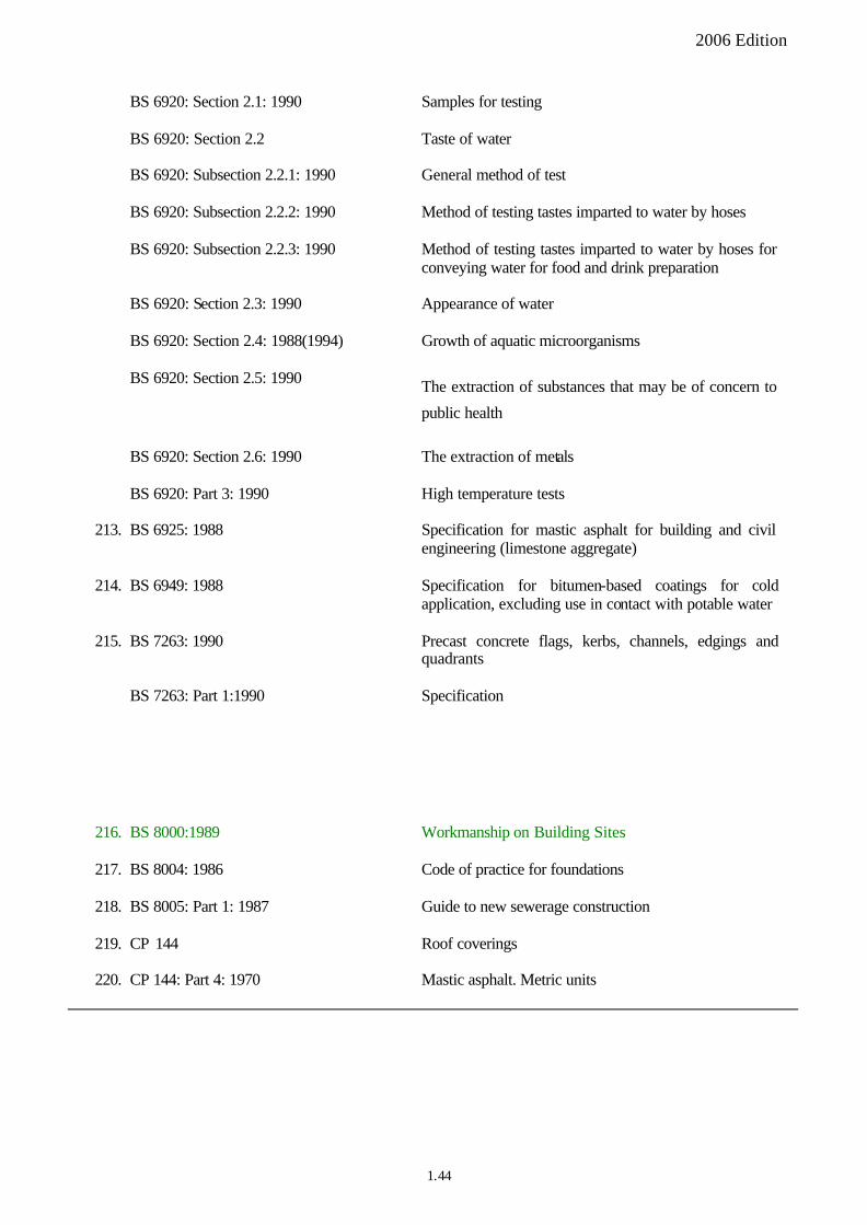
BS 7263: Part 1: 2001
Precast concrete flags, kerbs, channels, edgings and quadrants. Precast, unreinforced concrete paving flags and complementary fittings. Requirements and test methods
2006 Edition
BS 6920: Section 2.1: 1990 Samples for testing
BS 6920: Section 2.2 Taste of water
BS 6920: Subsection 2.2.1: 1990 General method of test
BS 6920: Subsection 2.2.2: 1990 Method of testing tastes imparted to water by hoses
BS 6920: Subsection 2.2.3: 1990 Method of testing tastes imparted to water by hoses for conveying water for food and drink preparation
BS 6920: Section 2.3: 1990 Appearance of water
BS 6920: Section 2.4: 1988(1994) Growth of aquatic microorganisms
BS 6920: Section 2.5: 1990 The extraction of substances that may be of concern to
public health
BS 6920: Section 2.6: 1990 The extraction of metals
BS 6920: Part 3: 1990 High temperature tests
213. BS 6925: 1988 Specification for mastic asphalt for building and civil engineering (limestone aggregate)
214. BS 6949: 1988 Specification for bitumen-based coatings for cold application, excluding use in contact with potable water
215. BS 7263: 1990 Precast concrete flags, kerbs, channels, edgings and quadrants
BS 7263: Part 1:1990 Specification
216. BS 8000:1989 Workmanship on Building Sites
217. BS 8004: 1986 Code of practice for foundations
218. BS 8005: Part 1: 1987 Guide to new sewerage construction
219. CP 144 Roof coverings
220. CP 144: Part 4: 1970 Mastic asphalt. Metric units
1.44
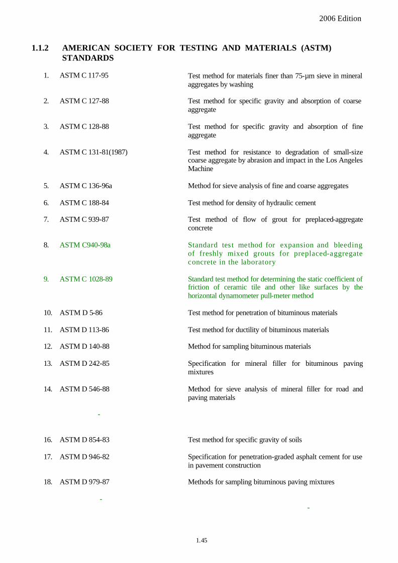
15. ASTM D790 2000 Measurement/Properties of internal lining for repair of pipelines and culverts: Flexural properties
19. ASTM D 562 81 (1997) Standard test method for consistency of paints measuring
krebs unit (KU) viscosity using a stormer type viscometer
2006 Edition
1.1.2 AMERICAN SOCIETY FOR TESTING AND MATERIALS (ASTM) STANDARDS
1. ASTM C 117-95 Test method for materials finer than 75-mm sieve in mineral aggregates by washing
2. ASTM C 127-88 Test method for specific gravity and absorption of coarse aggregate
3. ASTM C 128-88 Test method for specific gravity and absorption of fine aggregate
4. ASTM C 131-81(1987) Test method for resistance to degradation of small-size coarse aggregate by abrasion and impact in the Los Angeles Machine
5. ASTM C 136-96a Method for sieve analysis of fine and coarse aggregates
6. ASTM C 188-84 Test method for density of hydraulic cement
7. ASTM C 939-87 Test method of flow of grout for preplaced-aggregate concrete
8. ASTM C940-98a Standard test method for expansion and bleeding of freshly mixed grouts for preplaced-aggregate concrete in the laboratory
9. ASTM C 1028-89 Standard test method for determining the static coefficient of friction of ceramic tile and other like surfaces by the horizontal dynamometer pull-meter method
10. ASTM D 5-86 Test method for penetration of bituminous materials
11. ASTM D 113-86 Test method for ductility of bituminous materials
12. ASTM D 140-88 Method for sampling bituminous materials
13. ASTM D 242-85 Specification for mineral filler for bituminous paving mixtures
14. ASTM D 546-88 Method for sieve analysis of mineral filler for road and paving materials
-
16. ASTM D 854-83 Test method for specific gravity of soils
17. ASTM D 946-82 Specification for penetration-graded asphalt cement for use in pavement construction
18. ASTM D 979-87 Methods for sampling bituminous paving mixtures
--
1.45

28. ASTM D 2240 Standard test method for rubber property durometer hardness
29. ASTM D 2486 96 Standard test method for scrub resistance of wall paints
34. ASTM D 4329 Standard practice for fluorescent UV exposure of plastics
35. ASTM D 6307-98 Standard test method for asphalt content of hot-mix asphalt by ignition method
36. ASTM G 53-88 Practice for operating light and water-exposure apparatus (fluorescent UV condensation type) for exposure of non metallic materials
37. ASTM D4956 05 Standard Specification for Retroreflective Sheeting for Traffic Control
2006 Edition
20. ASTM D 1559-82 Test method for resistance to plastic flow of bituminous mixtures using Marshall apparatus
21. ASTM D 1754-87 Test method for effect of heat and air on asphaltic materials (thin-film over test)
22. ASTM D 2000-86 Classification system for rubber products in automobile applications
23. ASTM D 2027-76(1986) Specification for cutback asphalt (medium-curing type)
24. ASTM D 2041-95 Test method for theoretical maximum specific gravity of bituminous paving mixtures
25. ASTM D 2042-81(1985) Test method for solubility of asphalt materials in trichloroethylene
26. ASTM D 2171-88 Test method for viscosity of asphalts by vacuum capillary
27. ASTM D 2172-95 Test method for quantitative extraction of bitumen from bituminous paving mixtures
-
-
30. ASTM D 2726-96a Test method for bulk specific gravity of compacted bituminous mixtures using saturated surface-dry specimens
31. ASTM D 3203-94 Test method for percent air voids in compacted dense and open bituminous paving mixtures
32. ASTM D 3289-85 Test method for specific gravity or density of semi-solid and solid bituminous materials by nickel crucible
33. ASTM D 3359 Standard test methods for measuring adhesion by tape test
--
-
1.46
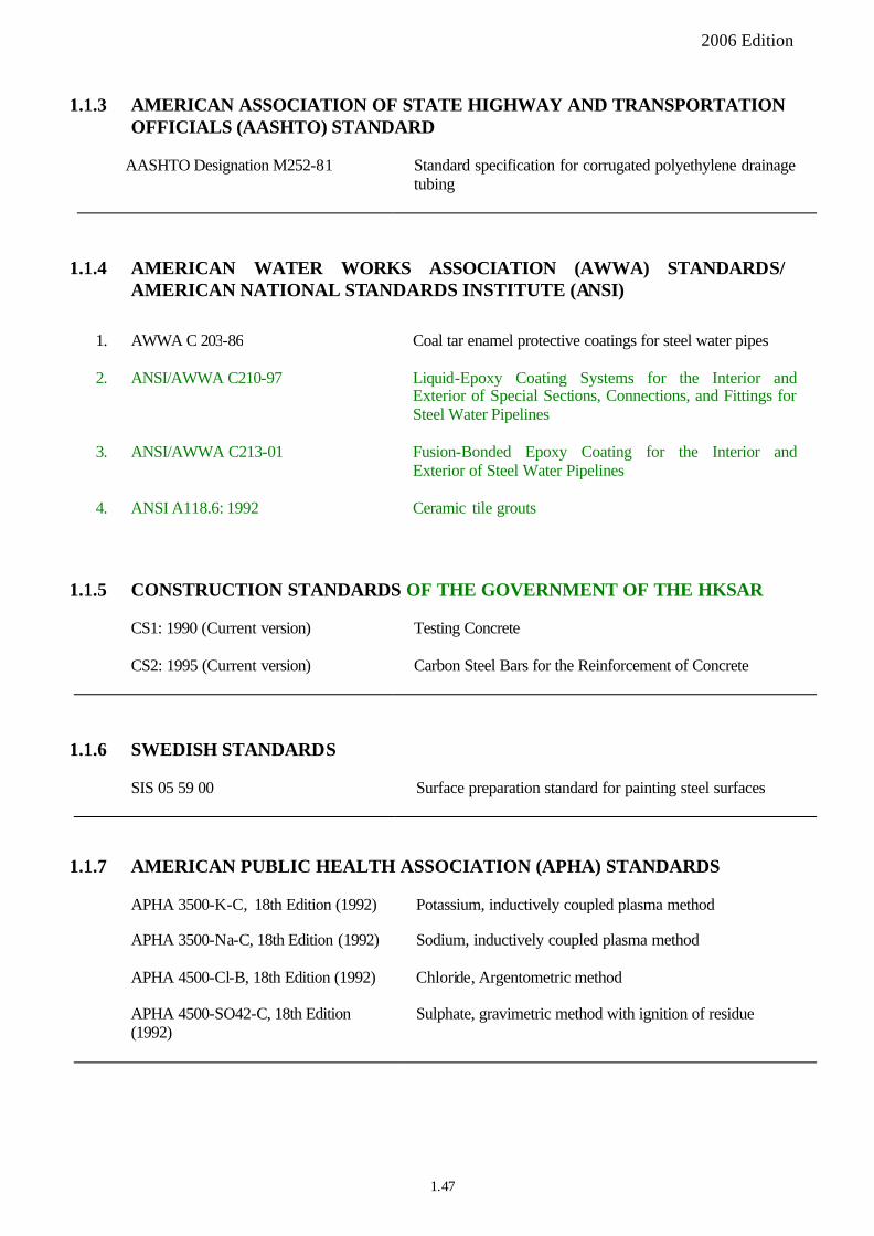
2006 Edition
1.1.3 AMERICAN ASSOCIATION OF STATE HIGHWAY AND TRANSPORTATION OFFICIALS (AASHTO) STANDARD
AASHTO Designation M252-81 Standard specification for corrugated polyethylene drainage tubing
1.1.4 AMERICAN WATER WORKS ASSOCIATION (AWWA) STANDARDS/ AMERICAN NATIONAL STANDARDS INSTITUTE (ANSI)
1. AWWA C 203-86 Coal tar enamel protective coatings for steel water pipes
2. ANSI/AWWA C210-97 Liquid-Epoxy Coating Systems for the Interior and Exterior of Special Sections, Connections, and Fittings for Steel Water Pipelines
3. ANSI/AWWA C213-01 Fusion-Bonded Epoxy Coating for the Interior and Exterior of Steel Water Pipelines
4. ANSI A118.6: 1992 Ceramic tile grouts
1.1.5 CONSTRUCTION STANDARDS OF THE GOVERNMENT OF THE HKSAR
CS1: 1990 (Current version) Testing Concrete
CS2: 1995 (Current version) Carbon Steel Bars for the Reinforcement of Concrete
1.1.6 SWEDISH STANDARDS
SIS 05 59 00 Surface preparation standard for painting steel surfaces
1.1.7 AMERICAN PUBLIC HEALTH ASSOCIATION (APHA) STANDARDS
APHA 3500-K-C, 18th Edition (1992) Potassium, inductively coupled plasma method
APHA 3500-Na-C, 18th Edition (1992) Sodium, inductively coupled plasma method
APHA 4500-Cl-B, 18th Edition (1992) Chloride, Argentometric method
APHA 4500-SO42-C, 18th Edition (1992)
Sulphate, gravimetric method with ignition of residue
1.47

1. BS EN: 196 1: 1995 Method of testing of Cement Part 1: Determination of strength
BS EN: 196 2: 1995 Method of testing of Cement Part 2: Chemical analysis
of cement
BS EN: 196 3: 1995 Method of testing of Cement Part 3: Determination of
setting time and soundness
BS EN: 196 6: 1992 Method of testing of Cement Part 6: Determination of
fineness
BS EN: 196 7: 1992 Method of testing of Cement Part 7: Methods of taking
and preparing samples of cement
BS EN: 196 21: 1992 Method of testing of Cement Part 21: Determination of the chloride, carbon dioxide and alkali content of cement
2. BS EN 197 1: 2000 Cement Part 1: Composition, specifications and
conformity criteria for common cements
3. BS EN 287: Part 1: 1992 Approval testing of welders for fusion welding Steels
4. BS EN 459: Part l : 2001 Building lime: definitions, specification and conformity criteria
5. BS EN 485: Part 1: 1994 Aluminium and aluminium alloys. Sheet, strip and plate.
Technical conditions for inspection and delivery
6. BS EN 485: Part 2: 2004 Aluminium and aluminium alloys. Sheet, strip and plate. Mechanical properties
BS EN 485: Part 3: 2003 Aluminium and aluminium alloys. Sheet, strip and plate. Tolerances on dimensions and form for hot rolled products
BS EN 485: Part 4:1994 Aluminium and aluminium alloys. Sheet, strip and plate. Tolerances on shape and dimensions for cold rolled products
7. BS EN 545: 2002 Ductile iron pipes, fittings, accessories and their joints for water pipelines
8. BS EN 571: Part 1: 1997 Non destructive testing. Penetrant testing. General principles
9. BS EN 598: 1995 Ductile iron pipes, fittings, accessories and their joints for sewerage applications
10. BS EN 754: Part 1:1997 Aluminium and aluminium alloys. Cold drawn rod/bar and tube. Technical conditions for inspection and delivery
2006 Edition
1.1.8 EUROPEAN STANDARDS ADOPTED AS BRITISH STANDARDS (BS EN)
- –
- –
- –
- –
- –
- –
- –
-
-
-
1.48

BS EN 754: Part 2:1997 Aluminium and aluminium alloys. Cold drawn rod/bar and tube. Mechanical properties
BS EN 754: Part 3:1996 Aluminium and aluminium alloys. Cold drawn rod/bar and tube. Round bars, tolerances on dimensions and form
BS EN 754: Part 4:1996 Aluminium and aluminium alloys. Cold drawn rod/bar and tube. Square bars, tolerances on dimensions and form
BS EN 754: Part 5:1996 Aluminium and aluminium alloys. Cold drawn rod/bar and tube. Rectangular bars, tolerances on dimensions and form
BS EN 754: Part 6:1996 Aluminium and aluminium alloys. Cold drawn rod/bar and tube. Hexagonal bars, tolerances on dimensions and form
BS EN 754: Part 7:1998 Aluminium and aluminium alloys. Cold drawn rod/bar and tube. Seamless tubes, tolerances on dimensions and form
BS EN 754: Part 8:1998 Aluminium and aluminium alloys. Cold drawn rod/bar and tube. Porthole tubes, tolerances on dimensions and form
11. BS EN 755: Part 1: 1997 Aluminium and aluminium alloys. Extruded rod/bar, tube and profiles. Technical conditions for inspection and delivery
BS EN 755: Part 2: 1997 Aluminium and aluminium alloys. Extruded rod/bar, tube and profiles. Mechanical properties
BS EN 755: Part 3: 1996 Aluminium and aluminium alloys. Extruded rod/bar, tube and profiles. Round bars, tolerances on dimensions and form
BS EN 755: Part 4: 1996 Aluminium and aluminium alloys. Extruded rod/bar, tube and profiles. Square bars, tolerances on dimensions and form
BS EN 755: Part 5: 1996 Aluminium and aluminium alloys. Extruded rod/bar, tube and profiles. Rectangular bars, tolerances on dimensions and form
BS EN 755: Part 6:1996 Aluminium and aluminium alloys. Extruded rod/bar, tube and profiles. Hexagonal bars, tolerances on dimensions and form
BS EN 755: Part 7:1998 Aluminium and aluminium alloys. Extruded rod/bar, tube and profiles. Seamless tubes, tolerances on dimensions and form
BS EN 755: Part 8:1998 Aluminium and aluminium alloys. Extruded rod/bar, tube
and profiles. Porthole tubes, tolerances on dimensions and form
2006 Edition
1.49
BS EN 755: Part 9:2001 Aluminium and aluminium alloys. Extruded rod/bar, tube and profiles. Profiles, tolerances on dimensions and form
12. BS EN 969: 1996 (2000) Ductile iron pipes, fittings, accessories and their joints for
gas pipelines
13. BS EN 970: 1997 Non destructive examination of fusion welds. Visual examination
14. BS EN 1008:2002 Mixing water for concrete. Specification for sampling, testing and assessing the suitability of water, including water recovered from processes in the concrete industry, as mixing water for concrete
15. BS EN 1011: Part 4: 2000 Welding. Recommendations for welding of metallic materials. Arc welding of aluminium and aluminium alloys
16. BS EN 1097 2: 1998 Test for mechanical and physical properties of aggregates Part 2 : Methods for the determination of resistance to fragmentation
17. BS EN 1342: 2001 Setts of natural stone for external paving. Requirements and test methods
18. BS EN 1344:2002 Clay pavers. Requirements and test methods
19. BS EN 1346:1999 Adhesives for tiles. Determination of open time
20. BS EN 1348:1999 Adhesives for tiles. Determination of tensile adhesion strength for cementitious adhesives
21. BS EN 1423:1998 Road marking materials. Drop on materials. Glass beads, antiskid aggregates and mixtures of the two
22. BS EN 1436:1998 Road marking materials. Road marking performance for road users
23. BS EN 1714: 1998 Non destructive examination of welded joints. Ultrasonic examination of welded joints
24. BS EN 1871:2000 Road marking materials. Physical properties
25. BS EN 10002: Part 1: 2001 Tensile testing of metallic materials. Method of test at ambient temperature
26. BS EN 10025: 1993: 2004 Hot rolled products of non alloy structural steels
Charpy impact test on metallic materials. Test method (V and U notches)
Stainless steels. List of stainless steels
2006 Edition
-
- –
-
27. BS EN 10045: Part 1: 1990 -
28. BS EN 10088-1:2005
29. BS EN 10137: 1996 Plates and wide flats made of high yield strength structural steels in the quenched and tempered or precipitation hardened conditions
1.50
30. BS EN 10223: 1998 Steel wire and wire products for fences
31. BS EN 10244-2: 2001 Steel wire and wire products. Non-ferrous metallic coatings on steel wire. Zinc or zinc alloy coatings
32. BS EN 10298:2005 Steel tubes and fittings for onshore and offshore pipelines. Internal lining with cement mortar
33. BS EN 12004:2001 Adhesives for tiles. Definitions and specifications
34. BS EN 12373: Part 1: 2001 Aluminium and aluminium alloys. Anodizing. Method for specifying decorative and protective anodic oxidation coatings on aluminium
35. BS EN 12899: Part 1: 2001 Fixed, vertical road traffic signs Part: 1 Fixed Signs
36. BS EN 22063: 1994
Metallic and Other Inorganic Coating Thermal Spraying Zinc, Aluminium and Their Alloys (F)
37. EN 63: 1977 (same as BS 2782: Part 10: Method 1005: 1977)
Glass reinforced plastics. Determination of flexural properties. Three point method.
1. BS EN ISO 178: 2003 Measurement/Properties of internal lining for repair of pipelines and culverts: Flexural properties
2. BS EN ISO 1461: 1999 (Replaces former BS 729)
Hot dip galvanized coatings on fabricated iron and steel articles. Specifications and test methods
BS EN ISO 3506: Part 2: 1998
2006 Edition
-
--
1.1.9 EUROPEAN STANDARDS (EN) and/or INTERNATIONAL ORGANIZATION FOR STANDARDIZATION (ISO) STANDARDS ADOPTED AS BRITISH STANDARDS (BS EN ISO)
3. BS EN ISO 3506: Part 1: 1998 Mechanical properties of corrosion-resistant stainless-steel fasteners. Bolts, screw and studs
Mechanical properties of corrosion-resistant stainless-steel fasteners. Nuts
4. BS EN ISO 4624:2003 Paints and varnishes. Pull-off test for adhesion
5. BS EN ISO 8492: 2004 Metallic materials tube flattening test
6. BS EN ISO 8501-1:2001 Preparation of steel substrates before application of paints and related products. Visual assessment of surface cleanliness. Rust grades and preparation grades of uncoated steel substrates and of steel substrates after overall removal of previous coatings
7. BS EN ISO 8502-3:2000 Preparation of steel substrates before application of paints and related products -- Tests for the assessment of surface cleanliness. Assessment of dust on steel surfaces prepared for painting (pressure-sensitive tape method)
1.51
2006 Edition
BS EN ISO 8502-6:2000 Preparation of steel substrates before application of paints and related products -- Tests for the assessment of surface cleanliness. Extraction of soluble contaminants for analysis -- The Bresle method
8. BS EN ISO 8503-1:1995 Preparation of steel substrates before application of paints and related products. Surface roughness characteristics of blast-cleaned steel substrates. Specific ations and definitions for ISO surface profile comparators for the assessment of abrasive blast-cleaned surfaces
BS EN ISO 8503-2:1995 Preparation of steel substrates before application of paints and related products. Surface roughness characteristic s of blast-cleaned steel substrates. Method for the grading of surface profile of abrasive blast-cleaned steel. Comparator procedure
BS EN ISO 8503-3:1995 Preparation of steel substrates before application of paints and related products. Surface roughness characteristics of blast-cleaned steel substrates. Method for the calibration of ISO surface profile comparators and for the determination of surface profile. Focusing microscope procedure
BS EN ISO 8503-4:1995 Preparation of steel substrates before application of paints and related products. Surface roughness characteristics of blast-cleaned steel substrates. Method for the calibration of ISO surface profile comparators and for the determination of surface profile. Stylus instrument procedure
9. BS EN ISO 9934: Part 1: 2001 Non-destructive testing. Magnetic particle testing. General principles
10. BS EN ISO 11124-1:1997 Preparation of steel substrates before application of paints and related products. Specifications for metallic blast-cleaning abrasives. General introduction and classification
11. BS EN ISO 11124-2:1997 Preparation of steel substrates before application of paints and related products. Specifications for metallic blast-cleaning abrasives. Chilled-iron grit
BS EN ISO 11124-3:1997 Preparation of steel substrates before application of paints and related products. Specifications for metallic blast-cleaning abrasives. High-carbon cast-steel shot and grit
BS EN ISO 11124-4:1997 Preparation of steel substrates before application of paints and related products. Specifications for metallic blast-cleaning abrasives. Low-carbon cast-steel shot
12. BS EN ISO 12944: 1998 Paints and varnishes. Corrosion protection of steel structures by protective paint systems.
13. BS ISO 14654: 1999 Epoxy-coated steel for the reinforcement of concrete
1.52

JIS Z 1902: 2000
1. ISO 1183: 1999 Plastics Methods for determining the density of
non cellular plastics
2. ISO 178: 2001 Plastics Determination of flexural properties
3. ISO 4591:1992 Plastics Film and sheeting Determination of average thickness of a sample, and average thickness and yield of a roll, by gravimetric techniques (gravimetric thickness)
4. ISO 4593:1993 Plastics Film and sheeting Determination of thickness by mechanical scanning
5. ISO 9001:2000 Quality management systems Requirements
WIS 4-34-04:1995 issue 2 Specification for renovation of gravity sewers by lining with crude-in-place pipes
WIS 4-52-01: 1992 Polymeric anti-corrosion (barrier) coatings
Manual of Sewer Condition Classification, 4th Ed, 2003
Coding system for recording of results
2006 Edition
14. BS ISO 14656:1999 Epoxy powder and sealing material for the coating of steel for the reinforcement of concrete
1.1.10 JAPANESE INDUSTRIAL STANDARDS (JIS)
Petrolatum tapes for corrosion protection
JIS A 6910 – 1988 Quality tests for multi-layer acrylic paint
1.1.11 INTERNATIONAL STANDARDS
ORGANIZATION FOR
--
-
-
STANDARDIZATION
-
(ISO)
- -
-
1.1.12 WATER INDUSTRY SPECIFICATION, WATER RESEARCH CENTRE
1.1.13 National Water Council, UK
1.53

2006 Edition
1.1.14 AUSTRALIAN/NEW ZEALAND STANDARDS (AS/NZS)
AS/NZS 4456.2:1997 Masonry units and segmental pavers – Methods of test. Method 2: Assessment of mean and standard deviation
AS/NZS 4456.14:1997 Masonry units and segmental pavers - Methods of test. Method 14: Determining water absorption properties
1.54
2006 Edition
APPENDIX 1.2
REQUIREMENTS FOR STEEL CONTAINER ROOM
General 1.2.1 As a reference, a standard steel container room of nominal size 6000 mm x 2500 mm x 2350 mm may accommodate up to a maximum of five standard curing tanks (see Appendix 1.3 – Clause 1.3.1(2)).
Equipment 1.2.2 Each steel container room shall be equipped with the following:
(a) A security door-lock.
(b) Windows with security metal grilles.
(c) Fluorescent lighting.
(d) Air-conditioner with heating and cooling facilities that is capable of keeping the room temperature at 25�C – 5�C.
(e) Adequate number of power sockets for operating the curing tanks.
(f) Water supply.
(g) Drainage outlets for connecting to the drainage valves and overflow system of the curing tanks.
1.55

2006 Edition
APPENDIX 1.3
REQUIREMENTS FOR CURING TANK
General 1.3.1 (1) The requirements for a curing tank shall be as stated in Appendix A of CS1.
(2) As a reference, a standard curing tank of nominal size 1650 mm x 860 mm x 510 mm has a capacity to accommodate about sixty-four number of 150 mm concrete cubes.
(3) For curing tanks of different non-standard sizes, the number of curing tanks required may be estimated on the basis of the capacity for a standard curing tank of equivalent volume at the discretion of the Engineer, who may require appropriate adjustments in the pump and heater capacities.
(4) Each curing tank shall be accessible for operation and maintenance.
(5) At least one stand-by curing tank shall be provided at all times.
Equipment 1.3.2 Each curing tank shall be constructed of corrosion-resistant material of adequate strength such as galvanized sheet steel to BS EN ISO 1461:1999 for hot-dip galvanized coating or BS 2569 for flame sprayed metal coating, fully welded on all seams and equipped with the following accessories:
(a) A lockable insulated lid (or cover) properly numbered.
(b) A recirculating water pump and a stand-by pump, both of a waterproof type and with capacity not less than 1000 litres per hour, earthed and fitted internally at one end of the tank drawing water through a pipe from the bottom to the diagonally opposite top of the tank at least 25 mm above the water level to stimulate efficient mixing of the water by free falling.
(c) A thermostatically controlled electric immersion heater and a stand-by heater, both with power of not less than 3 kW and connected through a temperature sensor for continual control of the water temperature at 27�C – 3�C.
(d) A set of three removable lower racks.
(e) A drainage valve and an overflow system.
(f) A steel stand supporting the water tank.
(g) Minimum/maximum thermometers for measuring water temperature.
(h) A switch panel.
Maintenance 1.3.3 Each curing tank shall be cleaned at regular intervals and the water in each tank be changed at least once a month in accordance with CS1 or as directed by the Engineer. In order to ensure adequate circulation of water and to facilitate the removal of test cubes from the curing tank, a gap of at least 15 mm shall be provided between the test cubes and the sides of the tank.
1.56