general engineering - national sugar institute
TRANSCRIPT

General Engineeringfor Post Graduate Diploma Course in Industrial Instrumentation & Process Automation (DIIPA)
(CANE HANDLING/CANE PREPARATION/MILLING)
by
Vinay KumarAssistant Professor (Sugar Engineering)
National Sugar Institute,
(Govt. of India)
Kanpur, Uttar Pradesh
Email : [email protected]
04/09/2020 1NATIONAL SUGAR INSTITUTE, KANPUR

Cane Unloading

Particular Type of motor H.P.
Hoisting Drum Drive Squirrel cage/slip ring induction motor
25-35
Holding Drum Drive Squirrel cage induction motor
25-35
Long Travel Drive Slip Ring induction motor 10
Cross Travel Drive Slip Ring induction motor 7.5
For a 2500/5000 TCD plant -Crane gantry : span - 30 metres , length - 40 metres (as per requirement)
Trolley
Grab

Name of the factory
TCD Crane parameters
Balrampur Chini Mills Ltd, Balrampur
7000 Span 22 meters x 57 meters Gantry Length
DSM Sugar Mills Ltd. ,Meerganj, Bareilly
5000 Span 24 meters x 80 meters Gantry Length

In a sugar factory cane comes from two modes :
1. Gate cane - (i) Cane comes in the factory by this mode with the help of bullock- Cart and Tractor-Trolley.
(ii) Unloaded with the help of Mechanical grab, Sling Bar (hooks & chains) or Hydraulic grab unloading.
(iii) Generally covers the cane in the radius of ……….. Km ?
2. Centre Cane- (i) Cane comes in the factory by this mode with the help of Trucks.
(ii)Unloaded with the help of tipplers.

Mode of supply………examples
Name of the Factory Capacity (TCD) Details of mode of supply
DSM Sugar Mills Ltd. ,Meerganj, Bareilly
5000•Truck - 40•Carts - 10•Trolleys - 60
Haryana Cooperative Sugar Ltd. Rohtak 3500
•Truck - 30•Carts - 18•Trolleys - 52

Sling Bar (hooks & chains)
Used for unloading bundled cane from trolleys and truck with the help of rope.

Grab
Mechanical Hydraulic

Cane Unloading…….
Truck TipplerThese are actuated by hydraulic drives which tilt the wagon/truck body resulting cane to slide into the carrier when inclination reaches about 45° to 50°

Factory Capacity (TCD)
Specifications
AVADH SUGAR & ENERGY LIMITED P.O. Hargaon, Distt. Sitapur
10000 Capacity : 50 M.T. Length & Width of platform : 9.5 mtr X 3.3 mtr Tilt angle : 550
DSM Sugar Mills Ltd. ,Meerganj, Bareilly
5000 Capacity – 40 MTAngle - 450
Rating – 10-12 Lift/hr


Cane Carrier

Cane Carrier
1. Horizontal Portion. Length of the horizontal portion
depends upon width of feeder tables and the space required for other unloading devices.
Width of carrier = the length of mill rollers for uniform and effective cane feeding into the mills.
Speed of carrier remains between 3
to 10 m/min.
2. Inclined Portion. Length : 14 to 17 m (3- roller mill) Slope varies from 15 to 22 degree. If less than 15° then cost of
installation and space occupied will increase.
If greater than 22° then cane will liable to slip and carrier would move without picking the cane up.
Cane carrier is a moving apron which conveys the cane from cane yard to feed into the mill. It has –
Ɵ
l
h
Dyno Drive

E.g… M/S Avadh Sugar and Energy Limited Seohara, Bijnor U.P.
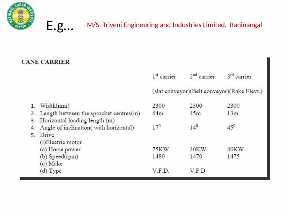
E.g… M/S. Triveni Engineering and Industries Limited, Raninangal

Cane Carrier………..
Bulk density
Type of Sugarcane Density in Kg/m3
Entangled 150
Loose pile 200
Bundle in pile 250
Mechanically harvested 300
Prepared by 2-knife set 480
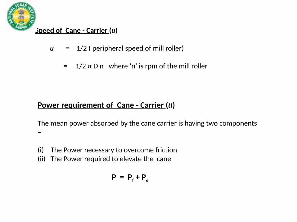
Speed of Cane - Carrier (u)
u = 1/2 ( peripheral speed of mill roller)
= 1/2 π D n ,where ‘n’ is rpm of the mill roller
Power requirement of Cane - Carrier (u)
The mean power absorbed by the cane carrier is having two components – (i) The Power necessary to overcome friction(ii) The Power required to elevate the cane
P = Pf + Pe

Cane Carrier………..
The Power necessary to overcome friction
where,
Pf = power necessary to overcome friction, in h.p.
Q = weight of cane on the carrier, in kg
K = half the total weight of the moving part of the carrier
( = weight of the upper or lower run of the conveyor)
f = coefficient of friction of the upper run ( ~ 0.30)
f’ = coefficient of rolling friction of the lower run (~0.15)
u = speed of the conveyor, in m/minλ = coefficient ( ~1.4 to 1.5), depending on the efficiency of gearing
transmitting the drive.

Cane Carrier………..
The Power necessary to elevate the cane
where,
Pe = power necessary to elevate cane, in h.p.
A = crushing rate of the mills, in t.c.h.H = difference in height between the highest part of the carrier and the
horizontal part of the carrier in the yard, in m λ = coefficient ( ~1.4 to 1.5), depending on the efficiency of gearing
transmitting the drive.
P = Pf + Pe

Cane preparation
The purpose of cane preparation is to cut cane into short pieces for feeding the mills and to rupture the cells, without extracting juice. This is achieved by set of rotating knives.
1st Set of Knives (Leveller/Kicker)
2nd Set of Knives
Fibrisor/Shredder
Clearance – The clearance of
a knife set is the distance
between the circle desired by the
extremity of the knives and the plane passing through the highest portions of carrier.
Required Preparatory Index - 85-90%
Methods of drive - (i) Steam turbine (ii) Electric Motor (SRIM) – LT or HT motors

Cane preparation………
1st set of Knives (Leveller/Kicker) It is required mainly to even out layer of cane. They are arranged to work with
high clearance and hence leave large portion of uncut cane.
Power requirement : 10-15 HP/tfhPitch : 50mm
2nd set of Knives : It is required to further prepare and
disintegrate the cane and having clearance lower than 1st set of knives.
Power requirement : 20-25 HP/tfhPitch : 20-22mm
"pitch" of knives is the mean distance, measured parallel to the axis, separating two successive circles of rotation.

Direction of rotation : Knives at the lowest part of their rotation will move in the
direction corresponding to the movement of the carrier. The opposite direction will have better preparation but
require more power.
Balancing : The knives set should be perfectly
balanced to avoid undesirable vibrations.
Factors for Power requirement : Tonnage of cane Fiber in the cane and its nature
(more/less resistant) Proportion of cane actually cut Number of blades Speed of rotation Radius of cutting circle friction, lubrication, wearing f knives.

Knives of preparatory Devices:
1. General Features
The knife blades are removable, so that they can be easily taken off for resharpening orfor replacement by another set of blades.
It is preferable to fix a knife to the arm in such a way that the edge affected by shocksis supported by a flange or a wide stirrup rather than fixing it so that shocks are absorbedby the bolts or pins securing the knife.
No. of blades/Knives : N = W/P – 1
Where, W is the width of carrier in cm P is the pitch of Knives in cm
When above eqn. gives an odd number for N, the even number immediately lower is generally adopted;

2. Design/types of knives/blades
(i) Reversible Knives
The working life of the blades is prolonged by diminishing wear of the cutting edge.Producing a self-sharpening effect of the knives on the
trailing edge, and so rendering them reversible
(ii) Hoe Knives
The radius of action remain constant with wear
They have the effect of a transverse cut due to the bent end of the knife and this transverse cut is superimposed on the longitudinal cut made
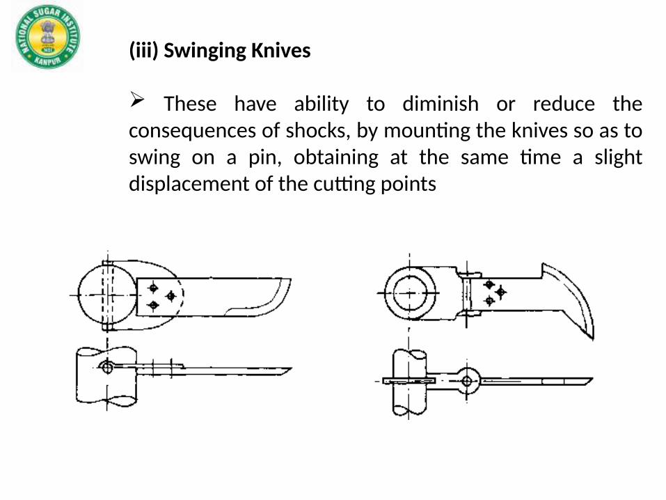
(iii) Swinging Knives
These have ability to diminish or reduce the consequences of shocks, by mounting the knives so as to swing on a pin, obtaining at the same time a slight displacement of the cutting points

Shredder
The object of the shredder is to complete the preparation and disintegration of the cane, so as to facilitate the extraction of juice by the mills.The shredder is placed at the head of the tandem, after the knives and before the first mill.Function : The shredder owes its existence and its value to the fact that the tissue of cane cells is very resistant; simple crushing between rollers, even under very high pressure, is not sufficient to break all the cells and extract the juice. On the other hand, if these cells can be torn open and disintegrated, the juice is liberated, becoming more accessible and more easily extracted. To obtain such an effect it is necessary to rupture the tissues: this is achieved by forcing the pieces of cane to pass through a very narrow space, thus blocking them on one side and striking them on the other side with a powerful blow; the hammer mill has been chosen with this object.
The shredder thus consists of a rotor carrying hammers which are pivoted on discs or plates; the end of the hammer passes very close to an anvil plate which is formed either with a saw-toothed profile

Shredder
Fibrizor
Position w.r.t carrier head…….

Milling

The function of Mill is extraction of juice from cane by the effect of pressure.
Important terms: Housing Feed arrangement (Donnelly chute) Roller Trash plate GroovingPressure in mills Scrapper Mill setting Imbibition

Three Roller Mill
The feed and discharge rolls are fixed, while the top roll is free to move up and down by means of a hydraulic pressure system.
Sl.No Size(D” X L”) TCD (max.)
1 24 x 48 1600
2 30 x 60 2880
3 33 x 66 3890
4 36 x 72 4580
5 40 x 80 5850

Grooving of Rollers
increases the capacity of the mill breaks up the bagasse more completely and thus
facilitates the extraction of the juice by the following mill
Circumfrential Grooves It is formed by grooving the roller with notches describing complete circles, in planes perpendicular to its axis Types
Fine : 5-20 mm pitch Medium : 20-25 mm Coarse : > 50mm

Messcharet Grooves
The grooving mainly adopted on feed rollers is also known by Messchaerts or Juice grooves. The only objective of such grooving is improvement of extraction. Special scrappers or combs are fitted so that the grooves are kept free of the bagasse.

Chevron Grooves
Such kind of grooving is adopted for basically griping on bagasse so that we can achieve improvement in feeding of bagasse. Chevron is placed only on two feeding rollers i.e. on top roller and on feed roller.
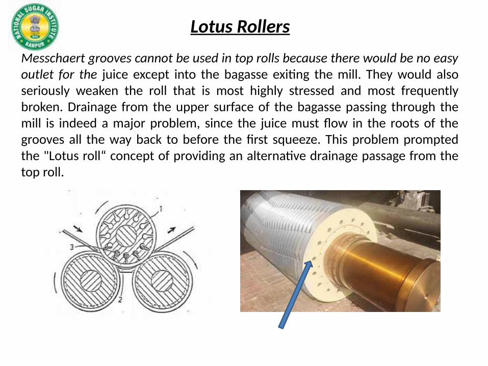
Lotus Rollers
Messchaert grooves cannot be used in top rolls because there would be no easy outlet for the juice except into the bagasse exiting the mill. They would also seriously weaken the roll that is most highly stressed and most frequently broken. Drainage from the upper surface of the bagasse passing through the mill is indeed a major problem, since the juice must flow in the roots of the grooves all the way back to before the first squeeze. This problem prompted the "Lotus roll“ concept of providing an alternative drainage passage from the top roll.

Mill feedingCane preparation coupled with high levels of imbibition render gripping of bagasse extremely difficult resulted development of new feeding methods had to overcome the mill feeding problem like Donelly chute,GRPF, TRPF,etc.
Donnelly chuteIn the gravity feed system closed feed chute is provided at an angle of 75° to 90° to the horizontal. The inner parts of this chute viz. the side plates have to be very smooth and are preferably of stainless steel to avoid frictional resistance and for easy flow of bagasse or prepared cane. It is usually provided at the first mill, where cane preparation is fine.
Underfeed rollersThe underfeed rollers usually are of cast iron and grooved, with diameters half to two thirds of the mill roller diameter. The drive for these rollers is provided from the mill rollers by pinion or chain. The peripheral speed is about 10% higher than that of the mill to which it is attached. These feed rollers require low power (5-10 hp.) and helps improve capacity and extraction of mills.

Continuous pressure feeders
(i) GRPF : This feeder consists of a pair of rollers mounted ahead of the mill and connected to the mill by closed chute of stainless steel, which has some what more opening towards the mill. These rolls extract good amount of juice reducing the load on the mill and rendering gripping action easy. The speed of these rollers is about 30-70% higher than that of the mill. They give positive improvement in capacity and extraction as they permit of addition of high imbibition and fine
(ii) TRPF : Toothed rings are fitted to rollers and are welded with hard faced electrodes for maintaining their condition as their wear affects the performance. The toothed rollers push the bagasse blanket towards the mill and provide more positive feed. The power requirement of toothed rollers is about half that for GRPF.