general catalogue 2014-2015 - azarnasimazarnasim.com/download/eng catalog.pdf · high temperature...
TRANSCRIPT

GENERAL CATALOGUE 2014-2015


9

10

11
*Advantages of Absorption chillers
The cooling process by a chiller in modern air conditioning systems marking comfort conditions with clean & fresh air for people who live in crowded & polluted cities & also for most of industrial applications plays very Important role. In this regards the LiBr + H2O absorption chillers with coefficient of performance (COP) greater than 0.7 because of following characteristics & many other reasons are more advisable than compression Chillers.
Absorption cooling cycle technology recognized as the First refrigeration cycle has been applied widely to space Conditioning & process cooling since 1886 i.e. for more Than 120 years ago. Absorption chillers are thermally flexible activated systems utilizing steam , hot & warm water , solar energy , clean liquid & gaseous fuels or Exhausted gases to power the absorption cycle.
A - Ozone FriendlyB - Non ToxicC - Non ExplosiveD - Stable Cycle Working FluidE - Minimal Electrical Power ConsumptionF - Minimal Total Energy ConsumptionG - Ability to Function with Wasted EnargyH - Low Noise & VibrationI - Extremely Longer Operating TimeJ - Wide Product Range & Model Selection for Cooling CapacityK - Lower Initial Price & Operating Costs Especially from Mediun to Super ModelsL - Simpler Installation, Operation & Maintenance, etc �.
Absorption
Chillers in
Comparison With
Compression
Chillers
12
You Have the Best Option With an Unique Reliability
AZAR NASIMABSORPTION CHILLER
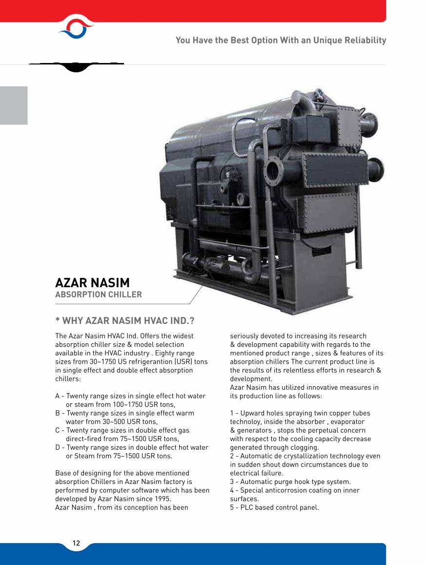
The Azar Nasim HVAC Ind. Offers the widest absorption chiller size & model selection available in the HVAC industry . Eighty range sizes from 30~1750 US refrigerantion (USR) tons in single effect and double effect absorption chillers:
A - Twenty range sizes in single effect hot water or steam from 100~1750 USR tons,B - Twenty range sizes in single effect warm water from 30~500 USR tons,C - Twenty range sizes in double effect gas direct-fired from 75~1500 USR tons,D - Twenty range sizes in double effect hot water or Steam from 75~1500 USR tons.
Base of designing for the above mentioned absorption Chillers in Azar Nasim factory is performed by computer software which has been developed by Azar Nasim since 1995.Azar Nasim , from its conception has been
seriously devoted to increasing its research & development capability with regards to the mentioned product range , sizes & features of its absorption chillers The current product line is the results of its relentless efforts in research & development.Azar Nasim has utilized innovative measures in its production line as follows:
1 - Upward holes spraying twin copper tubes technoloy, inside the absorber , evaporator & generators , stops the perpetual concern with respect to the cooling capacity decrease generated through clogging.2 - Automatic de crystallization technology even in sudden shout down circumstances due to electrical failure.3 - Automatic purge hook type system.4 - Special anticorrosion coating on inner surfaces.5 - PLC based control panel.
* WHY AZAR NASIM HVAC IND.?

13
Azar Nasim Double Effect Direct-Fired Absorption Chiller
6 - Special most recent enhancing techiques applied to all Components.
The above mentioned items are very important patents that are the crucial opening key to the world`s LIBr+H2O absorption chiller industry which had been under the shadow up to recent years.
General Design Features
The design , construction operational manulas for Absorption chillers covering all various different Units in operation require many pages of manulas to describe the situation at hand which is well out of the Scope of this brochure. Therefore , this brochure is intended to provide the required engineering data & information for understanding what makes the Azar Nasim absorption chillers product range including the following general design features:
1 - Design by computer software2 - Single shell design for single effect cycles & double Shell design for double effect cycles.3 - Solution & refrigerant low NPSH canned motor pumps with filters.
4 - Complate turnkey package including factory assembled & wired. For transportation, the control Panel may be shipped separately & installed at site. In case of larger sizes , the unit can be broken in to Smaler pieces & shipped in multiple units of Two or three Pieces for shipment.5 - Upward holes equipted spraying twin coppertubes Technology. Inside the absorber, vaporator, and generators , stops the perpetual concern with respect to the cooling capacity decrease generated thrugh cogging.6 - Automatic de crystallization technology even insudden shouts down circumstances due to electrical failure.
Stainless SteelFilter
Collector Canned Pump With Filter
14
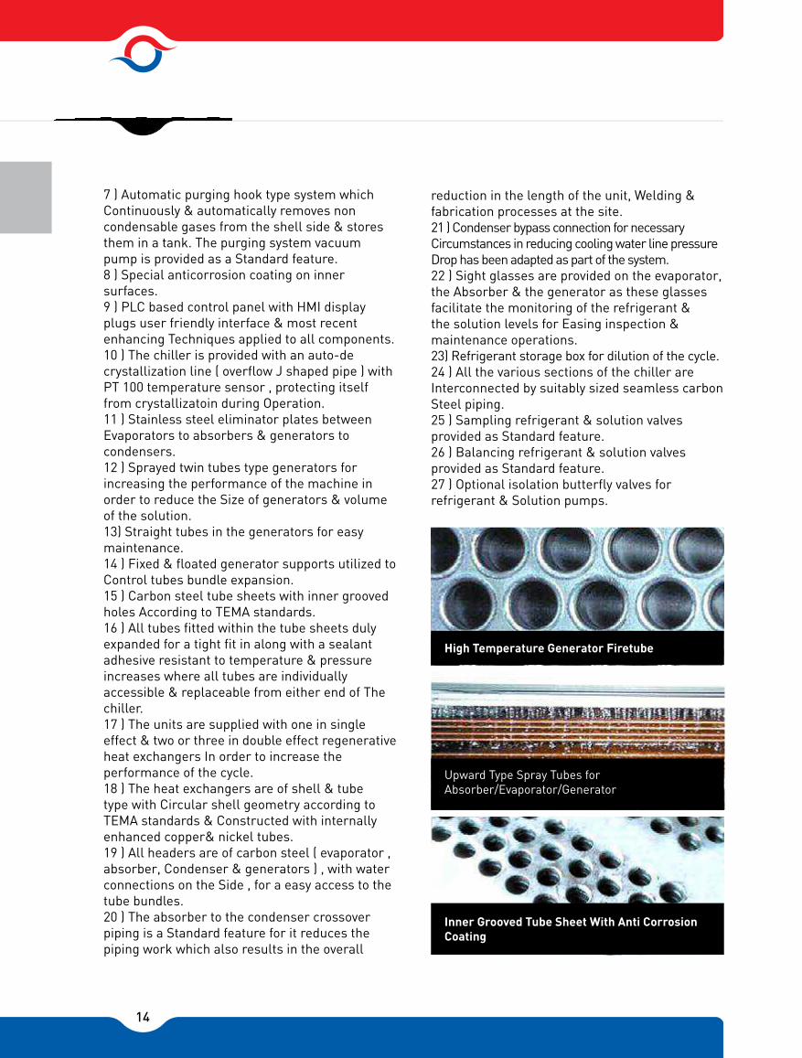
7 ) Automatic purging hook type system which Continuously & automatically removes non condensable gases from the shell side & stores them in a tank. The purging system vacuum pump is provided as a Standard feature.8 ) Special anticorrosion coating on inner surfaces.9 ) PLC based control panel with HMI display plugs user friendly interface & most recent enhancing Techniques applied to all components.10 ) The chiller is provided with an auto-de crystallization line ( overflow J shaped pipe ) with PT 100 temperature sensor , protecting itself from crystallizatoin during Operation.11 ) Stainless steel eliminator plates between Evaporators to absorbers & generators to condensers.12 ) Sprayed twin tubes type generators for increasing the performance of the machine in order to reduce the Size of generators & volume of the solution.13) Straight tubes in the generators for easy maintenance.14 ) Fixed & floated generator supports utilized to Control tubes bundle expansion.15 ) Carbon steel tube sheets with inner grooved holes According to TEMA standards.16 ) All tubes fitted within the tube sheets duly expanded for a tight fit in along with a sealant adhesive resistant to temperature & pressure increases where all tubes are individually accessible & replaceable from either end of The chiller.17 ) The units are supplied with one in single effect & two or three in double effect regenerative heat exchangers In order to increase the performance of the cycle.18 ) The heat exchangers are of shell & tube type with Circular shell geometry according to TEMA standards & Constructed with internally enhanced copper& nickel tubes.19 ) All headers are of carbon steel ( evaporator , absorber, Condenser & generators ) , with water connections on the Side , for a easy access to the tube bundles.20 ) The absorber to the condenser crossover piping is a Standard feature for it reduces the piping work which also results in the overall
reduction in the length of the unit, Welding & fabrication processes at the site.21 ) Condenser bypass connection for necessary Circumstances in reducing cooling water line pressure Drop has been adapted as part of the system.22 ) Sight glasses are provided on the evaporator, the Absorber & the generator as these glasses facilitate the monitoring of the refrigerant & the solution levels for Easing inspection & maintenance operations.23) Refrigerant storage box for dilution of the cycle.24 ) All the various sections of the chiller are Interconnected by suitably sized seamless carbon Steel piping.25 ) Sampling refrigerant & solution valves provided as Standard feature.26 ) Balancing refrigerant & solution valves provided as Standard feature.27 ) Optional isolation butterfly valves for refrigerant & Solution pumps.
Upward Type Spray Tubes for Absorber/Evaporator/Generator
High Temperature Generator Firetube
Inner Grooved Tube Sheet With Anti Corrosion Coating

15
28 ) LiBr solution refrigerant, corrosion inhibitor (Lithium Molybdate) & octyl alcohol provided separately & to be Charged at site.29 ) Nitrogen is charged at a pressure slightly greater than atmospheric pressure for shipping , in order to avoid air entering the machine in case of any accidents during Transport.30) Lifting lugs provided on each side of the unit.
Azar Nasim Double Effect Direct Fired Absorption Chiller/Heater
Cycle Components Internally and Externally Enhanced tubes
Headers with Water Connections on the Side High Stage Generator Fire Tube Turbulator
EXHAUST FLUE GASES
OPTIONAL WATER HEATING COIL
HOT WATERIN OUT
SOLUTION LEVEL CONTROL
TAPEREDINSERT TURBULATOR
HIGH TEMP HEAT EXCHANGER
FIRE TUBES
REFRACTORY CONCRETE
FIRE TUBE FURNACE
EXPANDED SHELL
LOW TEMP HEAT EXCHANGER
DRY BACK TYPE DIRECT FIRED HIGH TEMPERATURE GENERATOR
2.93 [kW/ton]
LOW TEMP GENERATOR
LIQUID JET PUMP
SOLUTION PUMP WITH STAINLESS
STEEL FILTER
CONDENSER
OUTLET COOLING WATER37.8 [°C]
6.7 [°C]
CHILLED WATER 9.1 [lit/min/ton]
12.2 [°C]
REFRIGERANT LEVEL CONTROL
REFRIGERANT PUMPWITH STAINLESS STEEL FILTER29.4 [°C]
11.2 [Lit/min/ton]
MAIN SHELL OF DIRECT FIRED ABSORPTION CHILLER
EVAPORATOR
ABSORBER
INLET COOLING WATER
16
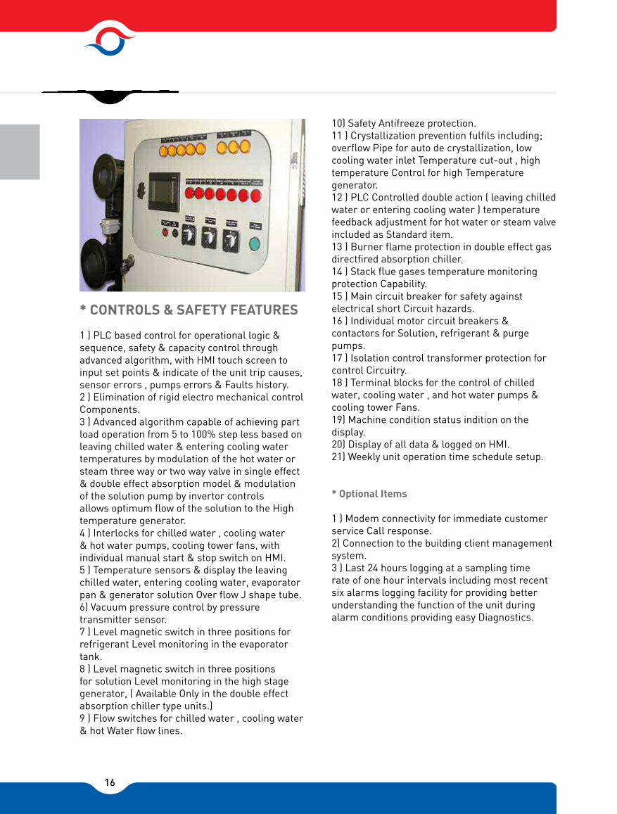
1 ) PLC based control for operational logic & sequence, safety & capacity control through advanced algorithm, with HMI touch screen to input set points & indicate of the unit trip causes, sensor errors , pumps errors & Faults history.2 ) Elimination of rigid electro mechanical controlComponents.3 ) Advanced algorithm capable of achieving part load operation from 5 to 100% step less based on leaving chilled water & entering cooling water temperatures by modulation of the hot water or steam three way or two way valve in single effect & double effect absorption model & modulation of the solution pump by invertor controls allows optimum flow of the solution to the High temperature generator.4 ) Interlocks for chilled water , cooling water & hot water pumps, cooling tower fans, with individual manual start & stop switch on HMI.5 ) Temperature sensors & display the leaving chilled water, entering cooling water, evaporator pan & generator solution Over flow J shape tube.6) Vacuum pressure control by pressure transmitter sensor.7 ) Level magnetic switch in three positions for refrigerant Level monitoring in the evaporator tank.8 ) Level magnetic switch in three positions for solution Level monitoring in the high stage generator, ( Available Only in the double effect absorption chiller type units.)9 ) Flow switches for chilled water , cooling water & hot Water flow lines.
* CONTROLS & SAFETY FEATURES
10) Safety Antifreeze protection.11 ) Crystallization prevention fulfils including;overflow Pipe for auto de crystallization, low cooling water inlet Temperature cut-out , high temperature Control for high Temperature generator.12 ) PLC Controlled double action ( leaving chilledwater or entering cooling water ) temperature feedback adjustment for hot water or steam valve included as Standard item.13 ) Burner flame protection in double effect gas directfired absorption chiller.14 ) Stack flue gases temperature monitoring protection Capability.15 ) Main circuit breaker for safety against electrical short Circuit hazards.16 ) Individual motor circuit breakers & contactors for Solution, refrigerant & purge pumps.17 ) Isolation control transformer protection for control Circuitry.18 ) Terminal blocks for the control of chilled water, cooling water , and hot water pumps & cooling tower Fans.19) Machine condition status indition on the display.20) Display of all data & logged on HMI.21) Weekly unit operation time schedule setup.
* Optional Items
1 ) Modem connectivity for immediate customer service Call response.2) Connection to the building client management system.3 ) Last 24 hours logging at a sampling time rate of one hour intervals including most recent six alarms logging facility for providing better understanding the function of the unit during alarm conditions providing easy Diagnostics.

17
* TESTING PROCEDURE
The LiBr type absorption chiller units working pressure is under vacuum conditions, so producing of these units is Very important with respect to leak tightness. Hence it is Necessary to perform the leak detection tests as follows.1 ) Tubes & shell sides Nitrogen test with pressure up To 3~5 [barg].2) Helium test (sniffing method).3 ) Tubes side hydraulic test with pressure up to 10 [barg] Or 1.5 times of working pressure.
Typical Solar Collector to produce heat for viuna - Azar Nasim Vila Model Absorption Chiller
Typical Steam/Hot Water Double Effect Absorption Chiller
CONDENSATE HEAT EXCHANGER
HIGH TEMP HEAT EXCHANGER
LOW TEMP HEAT EXCHANGER
2.93 [kW/ton]
LOW TEMP GENERATOR
LIQUID JET PUMP
SOLUTION PUMP WITH STAINLESS
STEEL FILTER
CONDENSER
OUTLET COOLING WATER37.8 [°C]
6.7 [°C]
CHILLED WATER 9.1 [lit/min/ton]
12.2 [°C]
REFRIGERANT LEVEL CONTROL
REFRIGERANT PUMPWITH STAINLESS STEEL FILTER29.4 [°C]
11.2 [Lit/min/ton]
EVAPORATOR
ABSORBER
INLET COOLING WATER
HIGH TEMP GENERATOR
STEAM IN
SUBCOOLED CONDENSATE OUT
5°C
18
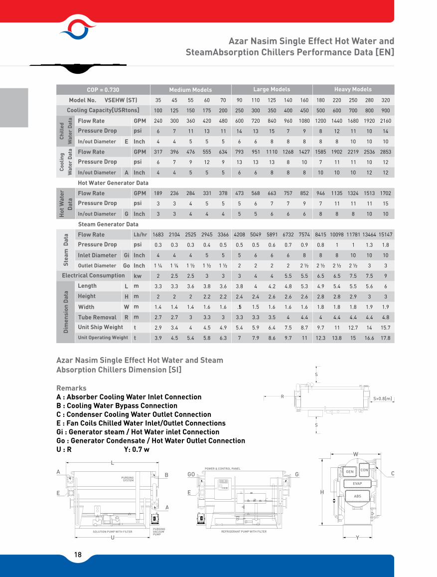
Azar Nasim Single Effect Hot Water and SteamAbsorption Chillers Performance Data [EN]
Azar Nasim Single Effect Hot Water and Steam Absorption Chillers Dimension [SI]
Remarks A : Absorber Cooling Water Inlet ConnectionB : Cooling Water Bypass ConnectionC : Condenser Cooling Water Outlet ConnectionE : Fan Coils Chilled Water Inlet/Outlet ConnectionsGi : Generator steam / Hot Water inlet ConnectionGo : Generator Condensate / Hot Water Outlet ConnectionU : R Y: 0.7 w
Dim
ensi
on D
ata
Stea
m D
ata
Dat
aH
ot W
ater
C
oolin
g
Wat
er D
ata
Chi
lled
Wat
er D
ata
COP = 0.730 Medium Models Large Models Heavy Models
Model No. VSEHW (ST)
Cooling Capacity[USRtons]
Electrical Consumption
Flow Rate
Pressure Drop
Flow Rate
Pressure Drop
Flow Rate
Pressure Drop
Flow Rate
Pressure Drop
Unit Ship Weight
Unit Operating Weight
Length
Height
Width
In/out Diameter
In/out Diameter
In/out Diameter
Inlet Diameter
Outlet Diameter
Tube Removal
E
A
G
Gi
Go
L
H
W
R
m
m
m
kw
m
GPM
psi
Inch
GPM
GPM
psi
psi
Inch
Inch
Lb/hr
psi
Inch
Inch
t
t
Hot Water Generator Data
Steam Generator Data
35
100
240
6
4
317
6
4
189
3
3
1683
0.3
4
1 ¼
2
3.3
2
1.4
2.7
2.9
3.9
45
125
300
7
4
396
7
4
236
3
3
2104
0.3
4
1 ¼
2.5
3.3
2
1.4
2.7
3.4
4.5
55
150
360
11
5
476
9
5
284
4
4
2525
0.3
4
1 ½
2.5
3.6
2
1.4
3
4
5.4
60
175
420
13
5
555
12
5
331
5
4
2945
0.4
5
1 ½
3
3.8
2.2
1.6
3.3
4.5
5.8
70
200
480
11
5
634
9
5
378
5
4
3366
0.5
5
1 ½
3
3.6
2.2
1.6
3
4.9
6.3
90
250
600
14
6
793
13
6
473
5
5
4208
0.5
5
2
3
3.8
2.4
1.5
3.3
5.4
7
110
300
720
13
6
951
13
6
568
6
5
5049
0.5
6
2
4
4
2.4
1.5
3.3
5.9
7.9
125
350
840
15
8
1110
13
8
663
7
6
5891
0.6
6
2
4
4.2
2.6
1.6
3.5
6.4
8.6
140
400
960
7
8
1268
8
8
757
7
6
6732
0.7
6
2
5.5
4.8
2.6
1.6
4
7.5
9.7
160
450
1080
9
8
1427
10
8
852
9
6
7574
0.9
8
2 ½
5.5
5.3
2.6
1.6
4.4
8.7
11
180
500
1200
8
8
1585
7
10
946
7
8
8415
0.8
8
2 ½
6.5
4.9
2.8
1.8
4
9.7
12.3
220
600
1440
12
8
1902
11
10
1135
11
8
10098
1
8
2 ½
6.5
5.4
2.8
1.8
4.4
11
13.8
250
700
1680
11
10
2219
11
10
1324
11
8
11781
1
10
2 ½
7.5
5.5
2.9
1.8
4.4
12.7
15
280
800
1920
10
10
2536
10
12
1513
11
10
13464
1.3
10
3
7.5
5.6
3
1.9
4.4
14
16.6
320
900
2160
14
10
2853
12
12
1702
15
10
15147
1.8
10
3
9
6
3
1.9
4.8
15.7
17.8
POWER & CONTROL PANEL
GO
E
REFRIGERANT PUMP WITH FILTER
GI GEN CON
EVAP
ABS
W
C
H
Y
A
E
SOLUTION PUMP WITH FILTER
B
L
A
U
PURGINGVACUUMPUMP
PURGINGSYSTEM
S
S
S

19
Chi
lled
Wat
er D
ata
Coo
ling
Wat
er D
ata
Dat
aH
ot W
ater
St
eam
Dat
aD
imen
sion
Dat
a
Hot Water Generator Data
Steam Generator Data
COP = 0.730
Model No. VSEHW (ST)
Cooling Capacity[USRtons]
Electrical Consumption
Flow Rate
Pressure Drop
Flow Rate
Pressure Drop
Flow Rate
Pressure Drop
Flow Rate
Pressure Drop
Unit Ship Weight
Unit Operating Weight
In/out Diameter
In/out Diameter
In/out Diameter
Inlet Diameter
Outlet Diameter
Length
Height
Width
Tube Removal
E
A
G
Gi
Go
L
H
W
R
Super Models General Conditions
m
m
m
kw
m
GPM
psi
Inch
GPM
GPM
psi
psi
Inch
Inch
Lb/hr
psi
Inch
Inch
t
t
350
1000
2400
8
12
3170
9
12
1890
8
3
16830
1
10
3
9
6
3
2
5
18
21
400
1150
2760
10
12
3646
11
12
2174
11
3
19355
1.3
10
3
12
6.5
3
2
5.5
20.7
23.8
460
1300
3120
14
12
4121
14
14
2457
14
4
21879
1.8
12
3
12
7.2
3.2
2
6
22.8
26.2
530
1500
3600
13
12
4755
14
14
2835
13
4
25245
1.7
12
4
15
7.2
3.2
2.2
6
24.7
28.6
600
1750
4200
13
14
5548
14
14
3310
13
4
29453
1.6
12
4
15
7.4
3.2
2.2
6
27.5
31.2
based on chiller capacity(USRtons)Cycle Components Heat Capacity (H.C.)
Conversion Table31m /hr = 4.4 GPM
°Cx1.8+32=°F
1 psi = 6895 Pa
1 MBH = 252 kcal/hr
1 USRtons = 3.517 kW
1 lb = 0.454 kg
Azar Nasim Single Effect Hot Water and Steam Absorption Chillers Performance Data [EN]
Azar Nasim Single Effect Hot Water and Steam Absorption Chillers Actual Cycle [SI]
7.7 kg/hr PER TONS STEAM FLOW RATE @P=143 [kPa-abs]7.2 lit/min PER TONS HOT WATER FLOW RATE
1. Rated Chilled Water Outlet/Inlet Temperature: 44 / 54 [°F]
2. Rated Cooling Water Inlet/Outlet Temperature: 85 / 103 [°F]
3. Rated Hot Water Inlet/Outlet Temperature: 230 / 212 [°F]
4. Rated Steam Pressure / Degree of Subcooling: 6[psig]/18 [°F]
5. Lowest Permitted Outlet Temperature for Chilled Water: 40 [°F]
6. Pressure Limit For Chilled, Cooling, & Hot Water Except Special Orders: 120[psi]
7. Fouling Factor For Chilled & Cooling Water: 0.5[[°F].ft2/MBH]
8. And for Hot Water: 0.25 [°F. ft2/MBH]9. Adjustable Chilled, Cooling, & Hot Water
Flow Rate: 70~120[%]10. LiBr Solution Concentration: 54 [%]11. Machine Room Temperature: 40 ~ 110
[°F] & Relative Humidity <85%
12[MBH]×Qchw=USRtons 1-Chilledwater H.C:(1+COP-1)×2-Cooling water H.C.: Qclw= QchwCOP-1×3-Generator H.C.: Qgen= Qchw
COP = 0.730
REF
RIG
ERA
NT
PR
ESSU
RE
[kPa
]
SOLUTION TEMPERATURE [°C]
�PTX DIAGRAM FOR STEAM & HOT WATER UNIT
80
70
60
5047
40
30
20
10
50
10 30 50 70 90 110 130
50
40
30
20
10
543
2
1
%54%62
%65
%70
%60
C
2
45
3
Ee1
%0
82 [°C]
39.4 [°C]100 [°C]
STEAM OR HOT WATERCOOLING WATER35 [°C]110 [°C]
99 [°C], 62 [°C]5 [°C]
51 [°C], 60 [°C]
35 [°C], 54 [°C]
29.4
[°C]
COOLING WATER
12 [ ]lit/min tons
6.7 [°C]
CHILLED WATER 9.1
12.2 [°C]
[ ]lit/min tons
SOLUTION PUMP WITH STAINLESS
STEEL FILTER
REFRIGERANT PUMPWITH STAINLESS STEEL FILTER
EVAPORATOR
ABSORBER
LIQUID JET PUMP
HEAT EXCHANGER

20
Azar Nasim Single Effect Warm Water Absorption Chillers Performance Data [EN]
Azar Nasim Single Effect Warm Water Absorption Chillers Dimension [SI]
Remarks A : Absorber Cooling Water Inlet ConnectionB : Cooling Water Bypass ConnectionC : Condenser Cooling Water Outlet ConnectionE : Fan Coils Chilled Water Inlet/Outlet ConnectionsGi : Generator Warm Water inlet ConnectionGo : Generator Warm Water Outlet ConnectionU : R Y: 0.7 w
COP = 0.730 Small Models Medium Models Large Models
Model No. VSELW
Chi
lled
w
ater
dat
aC
oolin
gw
ater
dat
aW
arm
w
ater
dat
aD
imen
sion
dat
a
Cooling Capacity[USRtons]
Flow Rate
Pressure Drop
In/out Diameter
Flow Rate
Pressure Drop
In/out Diameter
Flow Rate
Pressure Drop
In/out Diameter
Electrical Consumption
Length
Height
Width
Tube Removal
Unit Ship Weight
Unit Operating Weight
Warm Water Generator Data
E
A
G
L
H
W
R
GPM
psi
Inch
GPM
psi
Inch
GPM
psi
Inch
Kw
m
m
m
m
t
t
11
30
72
6
3
114
7
3
68
3
2 ½
1.7
2.1
1.9
1.3
1.6
1.5
2.0
14
40
96
6
3
152
7
3
90
3
2 ½
1.8
2.1
2
1.3
1.6
1.6
2.2
18
50
120
7
3
190
8
3
113
4
2 ½
1.8
2.1
2
1.4
1.6
1.8
2.5
21
60
144
8
3
228
8
3
136
4
3
2
2.1
2
1.4
1.6
2
2.8
25
70
168
6
4
266
7
4
158
3
3
2
2.7
2
1.4
2.2
2.6
3.6
28
80
192
9
4
304
10
4
181
4
3
2
3
2
1.4
2.5
3
4.3
32
90
216
11
4
342
12
4
203
4
3
2.5
3
2
1.4
2.5
3.4
4.5
35
100
240
6
4
380
7
5
226
4
3
2.5
3.4
2
1.5
2.7
3.9
5.3
45
125
300
7
4
476
6
5
282
4
4
3.5
3.4
2
1.5
2.7
4
5.8
55
150
360
10
5
571
8
5
339
4
4
3.5
3.6
2.1
1.5
3
4.5
6.3
60
175
420
13
5
666
12
5
395
5
4
3.5
3.8
2.2
1.6
3.3
5
7
70
200
480
11
5
761
8
6
451
3
5
4.5
3.7
2.2
1.6
3
6.3
8.5
80
225
540
14
5
856
11
6
508
4
5
4.5
3.8
2.2
1.6
3.3
6.9
9.2
90
250
600
13
6
951
10
8
564
4
5
6
3.8
2.5
1.7
3.3
8
10.3
100
275
660
13
6
1046
11
8
621
4
6
6
3.8
2.5
1.7
3.3
8.7
11
POWER & CONTROL PANEL
GO
E
REFRIGERANT PUMP WITH FILTER
GI GEN CON
EVAP
ABS
W
C
H
Y
A
E
SOLUTION PUMP WITH FILTER
B
L
A
U
PURGINGVACUUMPUMP
PURGINGSYSTEM
S
S
S

21
Azar Nasim Single Effect Warm Water Absorption Chillers Performance Data [EN]
Azar Nasim Single Effect Warm Water Absorption Chillers Actual Cycle [SI]
110 125 140 160 180
300 350 400 450 500
720 840 960 1080 1200
13 13 6 9 6
6 8 8 8 8
1141 1331 1521 1712 1902
10 10 6 9 8
8 8 10 10 10
677 790 903 1016 1128
4 4 5 6 5
6 6 8 8 8
6 8 8 10 10
4 4 4.8 5.3 4.9
2.5 2.6 2.6 2.6 2.8
1.7 1.8 1.8 1.8 1.8
3.3 3.3 4 4.4 4
9.3 10.5 12 13 14.5
11.8 13.6 15.8 17 19
COP = 0.730 Heavy Models
Model No. VSELW
Chi
lled
w
ater
dat
aC
oolin
gw
ater
dat
aW
arm
w
ater
dat
aD
imen
sion
dat
a
Cooling Capacity[USRtons]
Flow Rate
Pressure Drop
In/out Diameter
Flow Rate
Pressure Drop
In/out Diameter
Flow Rate
Pressure Drop
In/out Diameter
Electrical Consumption
Length
Height
Width
Tube Removal
Unit Ship Weight
Unit Operating Weight
Warm Water Generator Data
E
A
G
L
H
W
R
GPM
psi
Inch
GPM
psi
Inch
GPM
psi
Inch
Kw
m
m
m
m
t
t
General Conditions
based on chiller capacity(USRtons)Cycle Components Heat Capacity (H.C.)
Conversion Table31m /hr = 4.4 GPM
1 MBH = 252 kcal/hr
1 F=1.8 ×C + 32
1 USRtons = 3.517 kW
1 psi = 6895 Pa
1 lb = 0.454 kg
1. Rated Chilled Water Outlet/Inlet Temperature: 44/54 [°F]2. Rated Cooling Water Inlet/Outlet Temperature: 85/100 [°F]3. Rated Hot Water Inlet/Outlet Temperature: 195/180 [°F]4. Lowest Permitted Leaving Chilled Water Temp.: 40[°F]5. Pressure Limit For Chilled, Cooling, & Hot Water Except
Special Orders: 100[psig]6. Fouling Factor For Chilled, Cooling Water: 0.5[°F ft2/MBH]7. And for Hot Water: 0.25 [°F. ft2/MBH]8. Adjustable Chilled, Cooling, & Hot Water Flow Rate:
70~120[%]9. LiBr Solution Concentration: 54 [%]10. Machine Room Temperature: 40 ~ 110 [°F] & Relative
Humidity <85%
12[MBH]×Qchw=USRtons 1-Chilledwater H.C:(1+COP-1)×2-Cooling water H.C.: Qclw= QchwCOP-1×3-Generator H.C.: Qgen= Qchw
COP = 0.730
REF
RIG
ERA
NT
PR
ESSU
RE
[kPa
]
SOLUTION TEMPERATURE [°C]
�PTX DIAGRAM FOR WARM WATER UNIT
80
70
60
50
4340
30
20
10
50
10 30 50 70 90 110 130
50
40
30
20
10
543
2
1
%54
%65 %70
%57
C
2
45
3
Ee1
%54
%0
75 [°C]
37.8 [°C]82.2 [°C]
STEAM OR HOT WATERCOOLING WATER34 [°C]90.6 [°C]
99 [°C], 62 [°C]5 [°C]
47 [°C], 57 [°C]
33 [°C], 54 [°C]
29.4
[°C]
COOLING WATER
14.4 [ ]lit/min tons
6.7 [°C]
CHILLED WATER 9.1
12.2 [°C]
[ ]lit/min tons
SOLUTION PUMP WITH STAINLESS
STEEL FILTER
REFRIGERANT PUMPWITH STAINLESS STEEL FILTER
EVAPORATOR
ABSORBER
LIQUID JET PUMP
HEAT EXCHANGER
43 [°C]
8.6 lit/min PER TONS WARM WATER FLOW RATE

22
Azar Nasim Double Effect Direct-Fired Absorption Chillers/ Performance Data [EN]
Azar Nasim Double Effect Direct-Fired Absorption Chillers Dimension [SI]
Remarks A : Absorber Cooling Water Inlet ConnectionB : Cooling Water Bypass ConnectionC : Condenser Cooling Water Outlet ConnectionE : Fan Coils Chilled Water Inlet/Outlet ConnectionsF : Fan Coils Hot Water Inlet / Outlet Connections (Optional)G : Fleur Gases Oulet ConnectionU : R Y: 0.85 w
11
30
300
72
6
3
89
7
3
60
7
2 ½
6
0.25
G 6
2.2
2.1
1.9
1.8
1.6
1.8
2.5
Model No. VDEDF
Heating Capacity
COP = 1.200 Small Models Medium Models Large Models
Chi
lled
w
ater
dat
aC
oolin
gw
ater
dat
aH
eati
ngw
ater
dat
a
Cooling Caait
low ate
rere ro
not iaeter
low ate
rere ro
not iaeter
letrial Contion
ength
Height
idth
e eoal
nit hi eight
nit erating eight
H
i
nh
i
nh
i
nh
w
t
t
ton
[MBH]
ig
nh
Gas
Flo
wN
atur
al
i
eni
on d
ata
[SI]
rere ro
not iaeter
Cooling/Heating
Min. Inlet Pressure
Exhaust Dim.
low ate
14 18 21 25 28 32 35 45 55 60 70 80 90 100 110 125 140 160 180
40 50 60 70 80 90 100 125 150 75 200 225 250 275 300 350 400 450 500
400 500 600 700 800 900 1000 1250 1500 1750 2000 2250 2500 2750 3000 3500 4000 4500 5000
96 120 144 168 192 216 240 300 360 420 480 540 600 660 720 840 960 1080 1200
6 7 8 6 9 11 6 7 10 13 11 14 13 13 13 13 6 9 6
3 3 3 4 4 4 4 4 5 5 5 5 6 6 6 8 8 8 8
118 148 177 207 236 267 295 369 443 516 590 664 738 811 885 1033 180 1328 1475
7 8 8 7 10 12 7 6 8 12 8 11 10 11 10 10 6 9 8
3 3 3 4 4 4 5 5 5 5 6 6 6 6 8 8 8 8 10
80 100 120 140 160 180 200 250 300 350 400 450 500 550 600 700 800 900 1000
7 8 9 7 9 11 7 8 10 13 11 14 13 13 13 13 7 10 7
2 ½ 2 ½ 3 3 3 3 4 4 4 4 5 5 5 6 6 6 8 8 8
8 10 12 14 16 18 20 25 30 35 40 45 50 55 60 70 80 90 100
0.25 0.25 0.25 0.25 0.25 0.25 0.25 0.25 0.25 0.5 0.5 0.5 0.5 0.5 0.5 0.5 0.5 0.5 0.5
6 6 7 7 8 8 9 9 10 10 12 12 12 14 14 14 16 16 18
2.2 2.2 2.5 2.5 2.5 3.2 3.2 4.5 4.5 4.5 6 6 7 8 8 9 10 11 11
2.1 2.1 2.1 2.7 3 3 3.4 3.4 3.6 3.8 3.7 3.8 3.8 3.8 4 4 4.8 5.3 4.9
2 2 2 2 2 2 2 2 2 2.2 2.2 2.2 2.2 2.4 2.4 2.5 2.5 2.6 2.6
1.8 1.8 1.9 1.9 1.9 1.9 2.0 2.0 2.0 2.0 2.1 2.1 2.1 2. 2.2 2.3 2.4 2.5 2.6
1.6 1.6 1.6 2.2 2.5 2.5 2.7 2.7 3 3.3 3 3.3 3.3 3.3 3.3 3.3 4 4.4 4
2.0 2.2 2.4 2.6 2.8 3.0 3.3 3.5 3.9 4.3 4.6 4.9 5.3 5.6 6.5 7.2 7.9 8.6 9.5
2.8 3.2 3.5 3.8 4 4.4 4.8 5.2 5.8 6.3 6.7 7.2 7.8 8.4 9.5 10.4 11.5 12.7 13.9
A
E
BL
A
U
0.2~0.
F
0.5
Y+0.5 [m]
W+0.5 [m]
L
H
EA
B
E
S
S
0.5
S
G
R

23
Azar Nasim Double Effect Direct-Fired Absorption Chillers/ Heaters Performance Data [EN]
Azar Nasim Double Effect Direct-Fired Absorption Chillers Actual Cycle [SI]
Heavy Models
1 MBH = 252 kcalhr1 USRtons = 3517 kW
1 lb = 0.454 kg1 inch = 254 mm
G
Model No. VDEDF
Heating Capacity
COP = 1.200
Chi
lled
w
ater
dat
aC
oolin
gw
ater
dat
aH
eati
ngw
ater
dat
a
Cooling Caait
low ate
rere ro
not iaeter
low ate
rere ro
not iaeter
letrial Contion
ength
Height
idth
e eoal
nit hi eight
nit erating eight
H
i
nh
i
nh
i
nh
w
t
t
ton
[MBH]
ig
nh
Gas
Flo
wN
atur
al
i
eni
on d
ata
[SI]
rere ro
not iaeter
Cooling/Heating
Min. Inlet Pressure
Exhaust Dim.
low ate
General Conditions
based on chiller capacity(USRtons)Cycle Components Heat Capacity (H.C.)
Conerion ale
460
1300
13000
3120
14
12
3835
12
12
2600
12
10
260
05
28
26
72
32
34
60
240
300
220 250 280 320 350 400
600 700 800 900 1000 1150
6000 7000 8000 9000 1000011500
1440 1680 1920 2160 2400 2760
12 11 10 14 8 10
8 10 10 10 12 12
1770 2065 2360 2655 2950 3393
10 10 9 10 8 10
8 10 10 10 12 12
1200 1400 1600 1800 2000 2300
8 9 8 10 8 9
6 8 8 8 10 10
120 140 160 180 200 230
05 05 05 05 05
18 20 20 22 24 26
12 13 14 16 18 22
54 55 56 6 6 65
28 29 30 30 30 30
28 30 30 32 32 34
44 44 44 48 5 55
130 148 160 178 198 220
178 198 215 235 255 2801 psi = 6895 Pa1CFM 1699 m³/hr
1m³/hr = 4.4 GPM
05
°Cx1.8+32=°F
1. Rated Chilled Water Outlet/Inlet Temperature: 44/54 [°F]
2. Rated Cooling Water Inlet/Outlet Temperature: 85/100 [°F]
3. Rated Heating Water Outlet / Inlet Temperature: 150/140 [°F]
4. Lowest Permitted Outlet Temperature for Chilled Water : 40[°F]
5. Pressure Limit For Chilled, Cooling, & Heating Water Except Special Orders: 120[psi]
6. Fouling Factor For Chilled , Cooling & Heating Water: 0.5[°F.ft2/MBH]
7. Adjustable Chilled, Cooling, & Heating Water Flow Rate: 70~120[%]
8. Natural gas consumption is calculated by heating value: 50[MBH/CFM] or 7400 [kcal/m3]
9. LiBr Solution Concentration: 54 [%]10. Machine Room Temperature: 40 ~ 110 [°F] &
Relative Humidity <85%
12[MBH]×Qchw=USRtons 1-Chilledwater H.C:(1+COP-1)×2-Cooling water H.C.: Qclw= QchwCOP-1×3-High Temp. Generator H.C.: Qgen= Qchw
EXHAUST FLUE GASES
OPTIONAL WATER HEATING COIL
HOT WATERIN OUT
SOLUTION LEVEL CONTROL
TAPEREDINSERT TURBULATOR
HIGH TEMP HEAT EXCHANGER
FIRE TUBES
REFRACTORY CONCRETE
FIRE TUBE FURNACE
EXPANDED SHELL
LOW TEMP HEAT EXCHANGER
DRY BACK TYPE DIRECT FIRED HIGH TEMPERATURE GENERATOR
2.93 [kW/ton]
LOW TEMP GENERATOR
LIQUID JET PUMP
SOLUTION PUMP WITH STAINLESS
STEEL FILTER
CONDENSER
OUTLET COOLING WATER37.8 [°C]
6.7 [°C]
CHILLED WATER 9.1 [lit/min/ton]
12.2 [°C]
REFRIGERANT LEVEL CONTROL
REFRIGERANT PUMPWITH STAINLESS STEEL FILTER29.4 [°C]
11.2 [Lit/min/ton]
MAIN SHELL OF DIRECT FIRED ABSORPTION CHILLER
EVAPORATOR
ABSORBER
INLET COOLING WATER
Pre
f = R
EFR
IGER
AN
T P
RES
SUR
E [k
Pa]
Tsol = SOLUTION TEMPERATURE [°C]
CRYSTALLIZATION LINE
120
110
100
90
80
70
60
50
40
30
20
10
0130 140 150 160 170 180
198.5
150125100
70.14
5040
30
20
10
543
2
1
10 20 30 40 50 60 70 80 90 100 110 120
%65X=%55 %60
%707d
c
6
2
451
e
COP = 1.20
24
35 55
100 150
Chilled Water Data (54°F > 44°F Fouling Factor 0.5 [R.ft²/MBH])
240 360
6 11
4 5
295 443
7 8
4 5
118 177
3 4
3 4
986 1479
0.2 0.2
2½ 2½
1 1
3 4
3.4 3.6
2 2
1.8 1.8
2.7 3
3.0 3.5
4.0 4.6Dim
ensi
on D
ata
[SI]
Stea
m D
ata
COP = 1.200 Medium Models Large Models Heavy Models
Model No. VSEHW (HW)
Cooling Capacity
Electrical Consumption
Flow Rate
Pressure Drop
Flow Rate
Pressure Drop
Flow Rate
Pressure Drop
Flow Rate
Pressure Drop
Unit Ship Weight
Unit Operating Weight
Length
Height
Width
In/out Diameter
In/out Diameter
In/out Diameter
Inlet Diameter
Outlet Diameter
Tube Removal
E
A
G
Gi
Go
L
H
W
R
m
m
m
kw
m
GPM
psi
Inch
GPM
GPM
psi
psi
Inch
Inch
Lb/hr
psi
Inch
Inch
t
t
[USRtons]
Super Models
Chi
lled
w
ater
dat
aC
oolin
gw
ater
dat
aH
otw
ater
dat
a
Cooling Water Data (85°F > 100°F Fouling Factor 0.5 [R.ft²/MBH])
Hot Water Generator Data (320°F > 302°F Fouling Factor 0.25 [R.ft²/MBH])
Steam Generator Data (74[PSIg], 320°F > 203°F )
70 90 110 125 140 160 180 220 250 280 320 350 400 460 530 600 700
200 250 300 350 400 450 500 600 700 800 900 1000 1150 1300 1500 1750 2000
480 600 720 840 960 1080 1200 1440 1680 1920 2160 2400 2760 3120 3600 4200 4800
11 14 13 15 7 9 8 12 11 10 14 8 10 14 13 13 13
5 6 6 8 8 8 8 8 10 10 10 12 12 12 12 14 14
590 738 885 1033 1180 1328 1475 1770 2065 2360 2655 2950 3393 3835 4425 5163 5900
8 10 10 10 6 9 8 10 10 9 10 8 10 12 12 13 14
5 6 6 8 8 8 8 8 10 10 10 12 12 12 12 14 14
236 295 354 413 472 531 590 708 826 944 1062 1180 1357 1534 1770 2065 2360
4 5 5 6 6 7 7 9 10 11 12 7 9 11 10 11 12
4 5 5 6 6 6 8 8 8 10 10 10 10 10 12 12 12
1972 2465 2958 3451 3944 4437 4930 5916 6902 7888 8874 9860 11339 12818 14790 17255 19720
0.3 0.4 0.3 0.4 0.5 0.6 0.6 0.8 0.8 1 1.2 0.8 1 1.2 1.4 1.4 1.8
3 3 3 4 4 4 5 5 5 6 6 6 6 8 8 8 8
1¼ 1¼ 1¼ 1½ 1½ 1½ 2 2 2 2½ 2½ 2½ 2½ 3 3 3 3
5.5 6.5 7 8 9 10 11 12 13 14 15 16 18 20 22 24 26
3.7 3.8 4.0 4.0 4.8 5.3 4.9 5.4 5.5 5.6 6.0 6.0 6.5 7.2 7.2 7.4 8.0
2.2 2.2 2.4 2.5 2.5 2.6 2.6 2.8 2.9 3.0 3.0 3.0 3.0 3.2 3.2 3.2 3.2
2.0 2.0 2.3 2.3 2.3 2.5 2.5 2.5 2.7 2.7 2.8 2.8 2.8 3.0 3.0 3.0 3.0
3 3.3 3.3 3.3 4.0 4.4 4.0 4.4 4.4 4.4 4.8 5.0 5.5 6.0 6.0 6.0 6.6
4 4.5 5.5 6.2 7 7.8 9 10.5 13 14.5 16 18 20 22 24 26 28
5.2 5.8 7 7.7 8.3 9 10 11.5 12.8 14 15 17 18 20 22 24 26
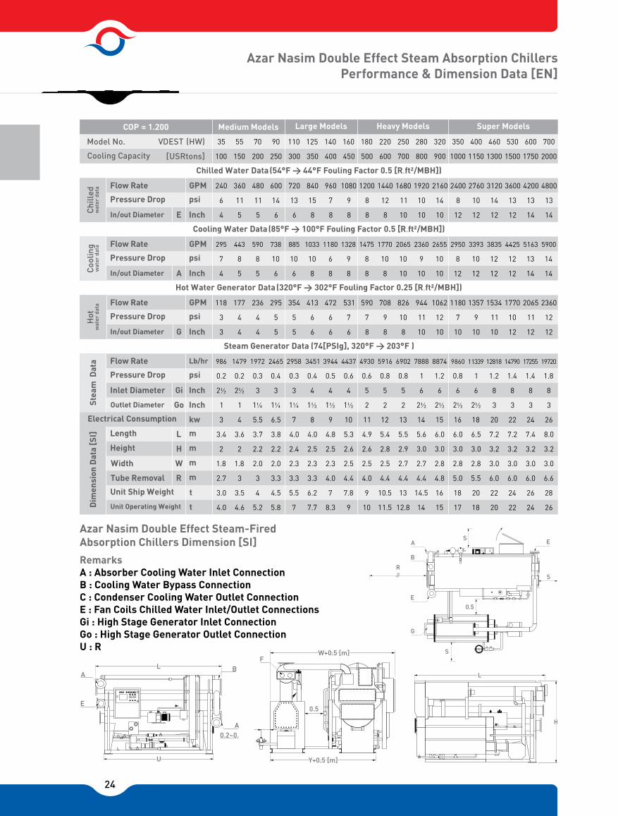
Azar Nasim Double Effect Steam Absorption Chillers Performance & Dimension Data [EN]
Azar Nasim Double Effect Steam-Fired Absorption Chillers Dimension [SI]
Remarks A : Absorber Cooling Water Inlet ConnectionB : Cooling Water Bypass ConnectionC : Condenser Cooling Water Outlet ConnectionE : Fan Coils Chilled Water Inlet/Outlet ConnectionsGi : High Stage Generator Inlet ConnectionGo : High Stage Generator Outlet ConnectionU : R
A
E
BL
A
U
0.2~0.
F
0.5
Y+0.5 [m]
W+0.5 [m]
L
H
EA
B
E
S
S
0.5
S
G
R
VDEST (HW)
Chilled Water Data (54°F > 44°F Fouling Factor 0.5 [R.ft²/MBH])

25
Model No. VSEV
COP = 0.750
Chi
lled
w
ater
dat
aC
oolin
gw
ater
dat
aW
arm
wat
er d
ata
Cooling Capacity
Flow Rate
Pressure Drop
Connection
Flow Rate
Pressure Drop
Connection
Electrical Consumption
Length
Height
Width
Unit Operating Weight
F
A
G
L
H
W
GPM
psi
Inch
GPM
psi
Inch
GPM
psi
Inch
Kw
m
m
m
Kg
[USRtons]
Dim
ensi
on
Pressure Drop
Connection
Flow Rate
based on chiller capacity (USRtons)Cycle Components Heat Capacity (H.C.)
General Conditions
data
Performance Data [EN]
2 4 6 8 10
5 10 15 20 25
12 24 36 48 60
8 10 10 12 12
1 ½ 1 ½ 2 2 2 ½
28 56 84 112 140
10 12 10 10 12
2 2 2 ½ 2 ½ 3
16.5 33 49.5 66 82.5
6 7 7 8 9
1 ½ 1 ½ 2 2 2 ½
0.35 0.35 0.65 0.65 0.75
1.1 1.2 1.4 1.6 1.8
1.7 1.7 1.8 1.8 1.9
1.0 1.0 1.2 1.4 1.4
550 750 900 1000 1200
Azar Nasim Model Absorption
Chillers Actual Cycle [SI]
Conversion Table31 m /hr = 4.4 GPM
°Cx1.8+32=°F
1MBH = 252 kcal/hr
1USRtons = 3.517 kW
1psi = 6895 Pa 1lb = 0.454 kg
Azar Nasim Villa Model Warm Water Absorption Chillers Performance Data [EN]
(Special Model for Operating with Solar System)
Remarks A : Absorber Cooling Water Inlet ConnectionC : Condenser Cooling Water Outlet ConnectionE : Fan Coils Chilled Water Inlet/Outlet ConnectionsGi : Generator Warm Water Inlet ConnectionGo : Generator Warm Water Oulet Connection
Azar Nasim Vila model have the same function as the Azar Nasim Outdoor packages but with low capacities between 5 to 25 USR tons. The features Are as follows.1 ) Easy installation, when the chiller is delivered to jobsite, only the chilled water Pipe, cooling water pipe & warm water pipe are connected to the chiller.2 ) No location requirement, chiller can be located on the rooftop or margin of the Building.3 ) Portable chiller, it can be carried on a vehicle & used for temporary exhibitions Or other areas.4 ) Special modeL, it can be operated with solar system.
1. Rated Chilled Water Outlet/Inlet Temperature: 44 / 54 [°F]2. Rated Cooling Water Inlet/2-Outlet Temperature: 85/95 [°F]3. 3- Rated Hot Water Inlet/Outlet Temperature: 185 175 [°F]4. Fouling Factor For Chilled, Cooling and Warm Water: 0.25
[°F.ft2/MBH].5. Electrical Specification: 50 [HZ] x 1 [PH] x 220 [Volt]
12[MBH]×Qchw=USRtons 1-Chilledwater H.C:(1+COP-1)×2-Cooling water H.C.: Qclw= QchwCOP-1×3-Generator H.C.: Qgen= QHot Water = Qchw
12.4 lit/min PER TONS WARM WATER FLOW RATE
35 [°C]79.4 [°C]
STEAM OR HOT WATERCOOLING WATER34 [°C]85 [°C]
99 [°C], 62 [°C]5 [°C]
47 [°C], 57 [°C]
33 [°C], 54 [°C]
29.4
[°C]
COOLING WATER
21.3[ ]lit/min tons
6.7 [°C]
CHILLED WATER 9.1
12.2 [°C]
[ ]lit/min tons
SOLUTION PUMP WITH STAINLESS STEEL FILTER
REFRIGERANT PUMPWITH STAINLESS STEEL FILTER
EVAPORATOR
ABSORBER
LIQUID JET PUMP
HEAT EXCHANGER
43 [°C]CONDENSER
GENERATOR
COP = 0.750
E
A
D
PURGINGVACUUMPUMP
GOGI
G C
E
A
W C
A H
S
S
S

26
Typical Piping System
Azar Nasim Single Effect Hot Water Absorption Chillers Typical Piping System (Summer Condition)
Azar Nasim Double Effect Direct-Fired Absorption Chillers Typical Piping System (Summer Condition)
COOLINGTOWER
COOLING WATER LINE
MAKE UP WATER(MUW)
ROOF
DRIN (D)FANCOILS CLOSEDEXPANSION TANK
N LINE2
D
MUW
CHILLED WATER LINE
CHILLED WATER VALVE “OPENED”
FROM FAN COILS OR AIR HANDLING UNITS
WARM WATER VALVE “CLOSED"
CHILLED WATER VALVE “OPENED”
WARM WATER VALVE “CLOSED"
DRAIN VALVE“OPENED”
HOT WATERBUTTERFLY VALVE
“CLOSED
HOT WTER LINE
COOLING WATERBY PASS FLOWBALANCINGGLOBE VALVE
D D D
CHILLED WATERPUMPS STATION“ON”
CHILLED WATERPUMPS STATION“ON”
ABSORPTIONCHILLER “ON”
@ AUTOMATIC MODETCWI
TCHO
INP
UTS
PLC
IN
CH
ILLE
R
OU
TPU
TS HOT WATER
PUMPS STATION“ON”
HOT WATER BOILER
AB
AB
M
HOT WATER CLOSEDEXPANSION TNK
N LINE2
DMUW
TO THE SERVICES
TANK HEATER FROM THE SERVICESDD
MUW
D
DFS
FS
D
FS
M
M
FS
D
TCHO
TCWI
MUW
BUTTERFLY VALVE OPENED
BUTTERFLY VALVE CLOSED
GLOB VALVE
VALVE
CHECK VALVE
INLINE FILTER
PRESSURE REGULATING VALVE
PROPORTIONAL 3 WAY VALVE
PROPORTIONAL 2 WAY VALVE
EXPANSION TANK AIR TRAP VALVE
FLOW SWITCH
DRAIN LINE ALL ؾ”
LEAVING CHILLED WATER PT100 SENSOR
ENTERING COOLING WATER PT100 SENSOR
MAKE UP WATER LINEOFF LINESON LINESPLC OUTPUT LINEPLC INPUT LINE
INP
UTS
PLC
IN
CH
ILLE
R
OU
TPU
TS
CHILLED WATER VALVE “OPENED”
WARM WATER VALVE “CLOSED"
COOLINGTOWER MAKE UP WATER
(MUW)
ROOF
DRIN (D)
D D
FS
FS
N LINE2
D
MUW
EXPANSION TANK
COOLING WATER LINE
FROM FAN COILS OR AIR HANDLING UNITS
TO FAN COILS OR AIR HANDLING UNITS
PLATE HEAT EXCHANGEERFOR DEMAND WARM WATER
HOT WATER PUMP
TO THE SERVICES
FROM SERVICES
MUW
CHILLED WATERPUMPS STATION“ON”
CHILLED WATERPUMPS STATION“ON”
DOUBLE EFFECT ABSORPTIONCHILLER/HEATER “ON”
@ AUTOMATIC MODE
FLUE GASESOUTLET
HIGH TEMPERATUREGENERATOR “ON”
CHILLED WATER LINE
WARM WATERVALVE “CLOSED”
CHILLED WATERVALVE “CLOSED”
TCHO
TCWI
TGENTFLUE
THWO
M
M
FS
D
TCHO
TCWI
MUW
BUTTERFLY VALVE OPENED
BUTTERFLY VALVE CLOSED
GLOB VALVE
VALVE
CHECK VALVE
INLINE FILTER
PRESSURE REGULATING VALVE
PROPORTIONAL 3 WAY VALVE
PROPORTIONAL 2 WAY VALVE
EXPANSION TANK AIR TRAP VALVE
FLOW SWITCH
DRAIN LINE ALL ؾ”
LEAVING CHILLED WATER PT100 SENSOR
ENTERING COOLING WATER PT100 SENSOR
MAKE UP WATER LINEOFF LINESON LINESPLC OUTPUT LINEPLC INPUT LINE
TFLUE
TGEN
THWO
FLUE GASES TEMPERATURE SENSOR
LEAVING HSG SOLUTION PT100 SENSOR
LEAVING HOT WATER TEMPERATURE SENSOR
27
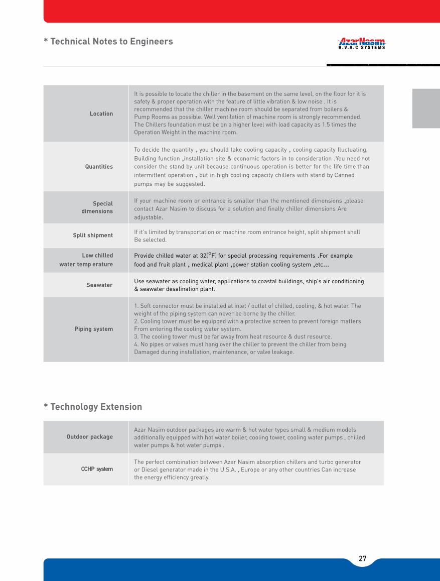
If it's limited by transportation or machine room entrance height, split shipment shallBe selected.
It is possible to locate the chiller in the basement on the same level, on the �oor for it issafety & proper operation with the feature of little vibration & low noise . It isrecommended that the chiller machine room should be separated from boilers &Pump Rooms as possible. Well ventilation of machine room is strongly recommended.The Chillers foundation must be on a higher level with load capacity as 1.5 times theOperation Weight in the machine room.
To decide the quantity , you should take cooling capacity , cooling capacity �uctuating, Building function ,installation site & economic factors in to consideration .You need notconsider the stand by unit because continuous operation is better for the life time thanintermittent operation , but in high cooling capacity chillers with stand by Cannedpumps may be suggested.
If your machine room or entrance is smaller than the mentioned dimensions ,pleasecontact Azar Nasim to discuss for a solution and nally chiller dimensions Areadjustable.
Provide chilled water at 32[°F] for special processing requirements .For examplefood and fruit plant , medical plant ,power station cooling system ,etc...
Use seawater as cooling water, applications to coastal buildings, ship's air conditioning & seawater desalination plant.
1. Soft connector must be installed at inlet / outlet of chilled, cooling, & hot water. Theweight of the piping system can never be borne by the chiller.2. Cooling tower must be equipped with a protective screen to prevent foreign mattersFrom entering the cooling water system.3. The cooling tower must be far away from heat resource & dust resource.4. No pipes or valves must hang over the chiller to prevent the chiller from beingDamaged during installation, maintenance, or valve leakage.
Quantities
Specialdimensions
Split shipment
Low chilledwater temp erature
Seawater
Piping system
Location
Azar Nasim outdoor packages are warm & hot water types small & medium models additionally equipped with hot water boiler, cooling tower, cooling water pumps , chilled water pumps & hot water pumps .
The perfect combination between Azar Nasim absorption chillers and turbo generator or Diesel generator made in the U.S.A. , Europe or any other countries Can increase the energy efciency greatly.
Outdoor package
CCHP system
* Technical Notes to Engineers
* Technology Extension

28
29
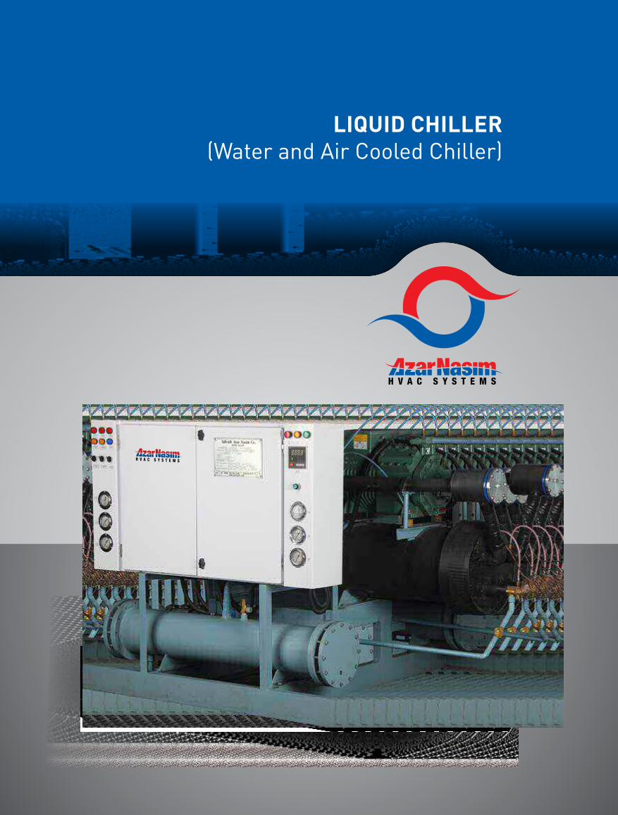
LIQUID CHILLER(Water and Air Cooled Chiller)
30
Azar nasim reciprocating water chillers are available in two types of air cooled and water cooled in capacity range of 3 to 240 tons of refrigeration and compressor configurations of one to four.Evaporators and condensers are high efficiency shell and tube heat exchangers which designed based on time (Tubular Exchanger Manufactures Association) standards.Safety controls installed on all units include high and low pressure cut-outs, compressor oil pressure safety cut � out, water anti freeze thermostat, water flow switch and evaporator entering water thermostat.The above mentioned are all chosen from the most recognized controlled manufacturers in the air conditioning industry. Compressors are by DWM COPELAND which happened to be one of the best and the most reliable brands.Raw materials such as copper tubes, fittings and valves are supplied by well-respected manufacturers. Electrical safety measures such as three phase controller, circuit breakers are available on all units.A fault detection system for the whole unit is available upon request. Microprocessor based PLC controller is also available as needed.
Features
Liquid Chiller (Water & Air Cooled Chiller)

31
Chilled water quantity and range:Required cooling capacity and the desired chilled water range are the two important factors in determining the amount of water to be circulated in the evaporator. This flow rate in (GPM) is given in the performance data tables.The Flowing formula can also be used when needed.
Tons × 24 GPM =
Chilled water range (ΔT) {˚F}
Water cooled chiller (ANCH-W) series:A 10 ˚F condenser water range is generally the best compromise for the most economical cooling tower selection to satisfy the chiller requirements. Based on the above suggestion and referring to performance data tables underdifferent condenser leaving water temperatures, we can extract the required condenser water flow rate are in (GPM) and the water side pressure drop (PD) . Refer to the Azar Nasim cooling tower catalogue for an appropriate cooling tower selection.
Condenser water temperature and heat pressure control:Since cooling towers are used in conjunction with water cooled condensers, the available condenser water temperature available shall be at least 5 ˚F above the ambient wet bulb temperature. For example if the ambient wet bulb
temperature is 80 ˚F, a properly sized tower will provide 85 ˚F Condenser water temperatures.For proper operation of a reciprocating water cooled chiller, it is necessary to maintain a condenser leaving watertemperature not lower than 85 ˚F. This means that a method of head pressure control such as controlling coolingtower fan via a thermostat or using a condenser water regulating valve in order to control the condenser water flow rate shall be employed.
Air cooled chiller (ANCH-A) series:ANCH-A units require the use of remotely located air cooled condensers. The column headed QC in the performancedata tables show the required THR capacity at each condensing temperature condition. Refer to the Azar Nasim air cooled condenser catalogue for an appropriate condenser selection.
Head pressure control and winter start in air cooled chillers:Air cooled condensers used with chillers must always include an accurate method of controlling the condensing pressure at 185 (psig) or higher. It is also necessary to determine the minimum outside air temperature at which the system will be operated. At an ambient temperature below 55 ˚F, a winter start system should be furnished with the condenser to enable the chiller to start without any difficulty.
Selection Information
General
Cooling Capacity is tabulated for all chiller models at a variety of conditions to cover most comfortCooling and industrial system requirements. The water cooled ANCH-W series are rated over a range of Leaving water temperatures of 42 ˚F to 46 ˚F and condenser leaving water temperatures of 85 ˚F to 105 ˚ F . The ANCH-A series are rated over the same evaporator chilled water range at condensing Temperatures of 115 ˚F to 135 ˚F.

32
Selection procedure
Water cooled models:
Given:Water flow rate to be chilled = 110 GPmDesign chilled water range = 10˚FEvaporator leaving water temp. = 45˚FDesign condenser water range = 10˚FCondenser leaving water temp. = 95˚ F
Determine unit model and size:Required cooling capacity:
GPM × Chilled water range 110 × 10 Qe = = = 24 24
45.83 tons of refrigeration
From the corresponding performance data table (Evap. Lvg water temp. = 45 ˚F) we select unit ANCH-60-2-W, offering 46.3 tons at 95 ˚F condenser leaving water temperature. From the same table we extract the evap. Water flow rate of 110.8 GPM and P.D. of 12.8 (ft² .in.wg) for ΔT = 10 ˚F.We can also determine the condenser water flow rate of 135.1 (GPM) and PD of 7.1 (ft² .in.wg), which the condenser (GPM) valve given above , refer to Azar Nasim cooling tower catalogue and select the required unit or units.
Air cooled models:
Given:Water flow rate to be chilled = 110 GPMDesign chilled water range = 10 ˚FEvaporator leaving water temp. = 45 ˚FDesign condensing temp. = 120 ˚FAmbient temp. = 100 ˚F
Determine unit model and Size:Required cooling capacity:
GPM × Chilled water range 110 × 10 Qe = = = 24 24
45.83 tons of refrigeration
From the corresponding performance data table (Evap. Lvg. Water temp. = 45 ˚F) we select unit ANCH-70-2-A, offering 52.2 tons at 120˚F condensing temp. From the same table we extract the evap water flow rate of 125 (GPM) and PD of 17.2 (ft². in.wg) for ΔT = 10 ˚F.
We can also extract the condenser THR capacity of 808.7 MBH. With this valve, refer to Azar Nasim air cooled condenser catalogue and selected the required unit or units.

33
All Compressor Models Dimensions
Note: For air cooled models, discharge & liquid line sizes are based on a maximum distance of 15 meters between chiller & air cooled condenser. D.L = Discharge Line L.L = Liquid Line
1700 600 1150 650 1000
1700 600 1250 650 1100
2000 600 1300 650 1100
2000 600 1300 650 1100
2500 600 1300 650 1100
2500 600 1300 650 1100
2500 600 1300 650 1100
2500 600 1450 650 1250
2500 600 1650 700 1400
2500 600 1650 700 1400
2500 750 1350 850 1150
2500 750 1400 850 1200
2500 750 1400 850 1200
2900 750 1400 850 1200
2900 750 1450 850 1250
2900 750 1500 850 1300
2900 850 1800 950 1550
2900 850 1800 950 1550
3000 800 1450 900 1200
3000 850 1500 950 1200
3500 850 1500 950 1200
3200 850 1600 950 1300
3500 900 1650 1000 1300
3500 950 1850 1050 1500
4000 1000 1900 1100 1500
3500 800 150 900 1250
3500 900 155 1000 1300
3500 900 155 1000 1300
3500 900 170 1000 1350
3500 1000 180 1100 1400
4000 1000 190 1100 1550
AN CH 5 - 1
AN CH 10 - 1
AN CH 15 - 1
AN CH 20 - 1
AN CH 25 - 1
AN CH 30 - 1
AN CH 35 - 1
AN CH 40 - 1
AN CH 50 - 1
AN CH 60 - 1
AN CH 30 - 2
AN CH 40 - 2
AN CH 50 - 2
AN CH 60 - 2
AN CH 70 - 2
AN CH 80 - 2
AN CH 100 - 2
AN CH 120 - 2
AN CH 60 - 3
AN CH 75 - 3
AN CH 90 - 3
AN CH 105 - 3
AN CH 120 - 3
AN CH 150 - 3
AN CH 180 - 3
AN CH 80 - 4
AN CH 100 - 4
AN CH 120 - 4
AN CH 140 - 4
AN CH 160 - 4
AN CH 200 - 4
AN CH 240 - 4
1500
1500
1800
1800
2300
2300
2300
2300
2300
2300
2300
2300
2300
2711
2711
2711
2711
2711
2811
2811
3311
3111
3311
3311
3811
3300
3300
3300
3300
3300
3800
4300
2”
3”
"5"5"5"5"5"6"6 4600 1100 200 1200 1550
Model
Table 1
A
700
700
700
700
700
1000
1000
1000
1000
1000
1400
1500
1500
1800
2050
2250
2250
2250
2250
2250
2600
2600
B
2×1½”
2×2”
2×3”
C D L W H W1 H1 D.L L.LW,A
1400
1400
1400
1400
1400
2×2”
2×2½”
2×2½”
2×2½”
2×2½”
2×3”
2×3”
4×2”
4×2½”
4×2½”
4×2½”
4×2½”
4×3”
4×3”
4×3”
2×3”4×2½”2×3”
2×3”4×2½”
4×2½”
4×2⅛”2×3”
4×3”
2×4”2×3”2×4”2×3”
1800
1800
1800
1800
2050
W,A
W,A
W,A
W,A
W,A
W,A
W,A
W,A
W,A
W,A
W,A
W,A
W,A
W,A
W,A
W,A
W,A
W,A
W,A
W,A
W,A
W,A
W,A
W,A
W,A
W,A
W,A
W,A
W,A
W,A
W,A
4×3”
4×3”
4×3”
4×3”
4×3”
4×4”
4×4”
1⅛”1⅜”1⅛”
1⅜”
1⅜”
1⅜”
1⅝”
1⅝”
1⅝”
1⅝”
1⅛”
2⅛”
2⅝”
2⅝”
2×1⅛”
2×1⅛”
2×1⅛”
2×1⅜”
2×1⅜”
2×1⅜”
2×1⅝”
2×1⅝”
2×⅞”
2×⅞”
2×1⅛”
2×1⅛”
2×1⅛”
2×1⅛”
2×1⅜”
2×1⅜”
1⅛”
1⅛”
1⅛”
1⅛”
1⅜”
1⅜”
1⅜”
1⅝”
1⅝”
⅝”
1⅛”
1⅜”
1⅜”
⅝”
⅞”
⅞”
⅞”
1⅛”
1⅛”
1⅛”
⅞”
1⅛”1⅜”1⅛”1⅜”1⅛”1⅜”1⅛”1⅜”
3×1⅜”
3×1⅜”
2×1⅛”
2×1⅜”
2×1⅜”
2×1⅜”
2×1⅜”
4×1⅜”
4×1⅜”
2×1⅝”
2×1⅝”
2×2⅛”
2×2⅛”
2×2⅛”
2×2⅝”
2×2⅝”
1½”
2”
2½”
2½”
3”
3”
3”
3”
3”
3”
3”
3”
4”
4”
5”
5”
3”
4”
4”
5”
5”
5”
6”
Dimensions
1⅛”

34
Dimensions for All Compressors Models
L
A
C
B
VIEW = Y
H
W
Y
L
A
C
VIEW = X
D L L L
H1
W1
X
D

35
PERFORMANCE DATA; FOR Water COOLED CHILLERSEVAPORATOR LEAVING WATER TEMP. = 42˚(F)
QE = Actual Evaporator Cooling Capacity. [1 tons of ref. = 12000 BTU / HR] WC = Compressor Motor- Power Input at 380 V, 3Ø, 50 Hz PD = Water Pressure Drop [Ft. WG] W.F.D. = Water Flow Data
95 10585
Tons Tons Tons KW KWGPM GPM GPMGPM GPM GPMPD PD PDPD PD PD
4.3
8.4
36.3
40.9
22.2
85.9
128.0
73.0
108.1
57.2
83.8
50.6
75.8
40.8
61.2
34.1
50.6
27.2
42.9
28.9
25.2
20.4
17.1
13.7
11.1
4.0
7.1
29.5
32.7
18.8
71.0
106.8
53.0
88.5
51.2
75.2
42.9
64.1
34.2
51.1
27.6
41.3
21.8
36.0
25.7
21.4
17.0
13.8
10.9
9.4
5.2
9.7
42.0
49.0
25.3
46.0
98.2
84.0
145.8
65.0
124.7
57.5
95.7
46.2
86.3
38.5
69.2
30.7
57.2
32.8
28.7
23.1
19.3
15.4
12.7
AN CH 5 1 W
AN CH 10 1 W
AN CH15 1 W
AN CH 20 1 W
AN CH 30 1 W
AN CH 35 1 W
AN CH 40 1 W
AN CH 50 1 W
AN CH 60 1 W
AN CH 30 2 W
AN CH 40 2 W
AN CH 50 2 W
AN CH 60 2 W
AN CH 70 2 W
AN CH 80 2 W
AN CH 100 2 W
AN CH 120 2 W
AN CH 60 3 W
AN CH 75 3 W
AN CH 90 3 W
AN CH 105 3 W
AN CH 120 3 W
AN CH 150 3 W
AN CH 180 3 W
AN CH 25 1 W
Condenser Leaving Water Temperature (°F)Table 2
Model Evap.W.F.D.
�T=10°F]
Cond.W.F.D.
�T=10°F]
QE WC Evap.W.F.D.
�T=10°F]
Cond.W.F.D.
�T=10°F]
QE WC Evap.W.F.D.
�T=10°F]
Cond.W.F.D.
�T=10°F]
QE WC
4.8 10.3 13.71.3 2.1
8.4 20.1 25.62.2 5.1
35.5 86.9 112.28.0 5.3
38.2 97.9 5.010.7 122.8
22.2 4.0 4.153.2 67.8
85.9 10.5 6.4205.6 266.5
127.5 306.4 6.413.2 397.2
71.0 12.5 5.3174.0 224.7
106.5 258.8 5.313.8 334.6
59.3 15.5 3.7137.0 175.5
88.3 200.6 3.714.4 256.4
51.0 16.6 4.2121.1 155.1
76.2 181.5 4.210.8 230.4
39.6 11.1 6.097.7 123.6
59.3 146.5 6.011.0 183.9
32.7 6.8 7.981.6 103.0
48.9 121.1 7.913.0 153.0
25.4 3.6 5.065.1 81.8
43.0 102.7 131.55.5 6.4
29.8 69.2 88.64.0 3.8
25.5 60.3 77.46.5 4.2
19.8 48.8 61.84.0 6.0
16.4 40.9 51.73.1 8.0
12.7 32.8 41.32.7 5.1
11.2 26.6 34.02.1 4.2
4.72.5 2.34.412.4 11.22.8 1.615.5 14.4
9.05.9 5.57.923.2 21.62.8 2.527.8 26.7
39.06.2 5.532.5100.5 93.39.5 8.8121.3 116.4
43.4 35.112.7 5.8 5.411.7110.1 103.9 126.6131.1
23.8 20.46.2 5.04.9 4.560.6 57.0 70.372.7
89.6 77.214.9 11.68.0 7.2235.1 214.5 269.1285.0
134.6 115.819.0 8.0 7.215.5349.0 322.3 403.0424.0
78.4 64.514.5 13.36.1 5.5201.1 187.7 233.7242.0
116.2 97.218.3 6.1 5.515.7298.5 278.2 347.1360.8
61.0 54.916.5 16.14.5 4.1155.6 146.1 181.5188.4
89.8 81.418.0 4.5 4.116.3229.1 215.0 265.8275.4
53.9 47.017.5 17.05.2 4.7137.7 129.1 160.1165.9
80.7 70.214.0 5.2 4.712.3206.6 193.2 238.0246.7
43.4 36.713.2 12.07.1 6.6110.6 103.9 127.7132.5
65.1 54.914.0 7.1 6.612.4165.7 155.9 190.0197.2
36.2 30.28.7 7.89.1 8.592.2 86.7 106.2109.9
53.7 45.216.5 9.1 8.514.7137.0 128.6 157.8163.3
28.9 23.45.3 4.35.8 5.473.5 69.0 84.487.4
44.88.0 7.238.6117.3 107.37.5 6.5142.6 132.9
30.84.6 4.227.578.5 73.75.7 4.795.0 91.6
27.05.2 4.723.368.7 64.68.2 7.482.9 80.2
21.77.1 6.618.355.3 52.05.3 4.666.3 63.9
18.19.2 8.615.146.2 36.24.0 3.555.1 53.3
14.25.9 5.511.836.9 34.03.3 2.944.1 42.7
11.95.0 4.610.330.4 28.53.4 3.036.5 35.2
KW
54.0
171.0
144.0
111.8
101.0
81.4
68.1
43.3
142.0
117.7
100.5
85.4
66.9
55.1
960.
194.3
165.8
127.4
115.0
92.3
76.9
AN CH 80 4 W
AN CH 100 4 W
AN CH 120 4 W
AN CH 140 4 W
AN CH 160 4 W
AN CH 200 4 W
AN CH 240 4 W
AN CH 80 4 W
AN CH 100 4 W
AN CH 120 4 W
AN CH 140 4 W
AN CH 160 4 W
AN CH 200 4 W
AN CH 240 4 W
50.6 11.9 3.7161.1
171.2 11.8 8.7409.4 529.2
141.6 11.5 8.6344.7 445.6
117.7 11.7 6.9267.7 342.3
101.6 15.8 5.3241.8 307.0
78.9 7.4 6.4194.9 244.7
65.2 6.9 5.3163.0 204.3
46.757.315.0 13.34.5 4.1145.8 137.2 166.2172.3
154.5179.016.8 13.49.8 9.1465.1 428.6 537.2565.0
130.0154.816.1 14.09.7 9.0397.0 370.6 462.7479.8
108.4119.915.3 13.48 7.5305.0 287.1 355.0367.2
93.1108.317.8 16.96.4 5.8275.3 258.6 317.7328.8
73.186.59.5 8.48 7.2221.0 207.1 252.8262.1
60.372.38.5 7.86.1 5.5184.1 173.1 210.7218.0
129.3

36
PERFORMANCE DATA; FOR AIR COOLED CHILLERSEVAPORATOR LEAVING WATER TEMP. = 42˚(F)
QE = Actual Evaporator Cooling Capacity. [1 tons of ref. = 12000 BTU/HR] WC = Compressor Motor-Power Input at 380 V, 3Ø, 50 Hz PD = Water Pressure Drop [Ft. WG] QC = Condenser total heat - rejection {MBH = 1000 BTU/HR} W.F.D. = Water Flow Data
Condensing Temperature (°F)
Tons Tons Tons Tons
4.3 4.1 4.0 3.61.4 1.2 1.2 1.0
5.8 5.6 5.4 5.0
8.2 8.0 7.8 7.4
4.3 4.0 3.7 3.2
6.6 6.1 5.7 5.1
4.2 3.9 3.6 3.1
3.2 3.0 2.8 2.5
2.8 2.6 2.4 2.1
2.2 2.0 1.7 1.4
2.2 2.1 2.0 1.7
4.8 5.0 5.2 5.69.6 8.6
22.0 19.624.3 25.1 26.74.2 4.0 3.722.7
41.7
54.4 52.7 50.9 47.3 61.257.653.7 55.7
38.9 36.2 86.746.240.3 42.0 43.511.1
12.1 11.4 10.7 9.2
10.6 10.1 8.8
14.0
14.4 13.1 12.0 10.0
13.6 12.0 10.0
13.4
12.7 12.2 11.7 10.7
12.6 11.8 11.1
14.6
11.9 11.0 10.1 8.4
13.7 12.8 11.0
11.1
16.0 15.4 14.8 13.7
10.3 9.5 8.0
11.1
7.5 6.9 6.3 5.4
10.4 9.7 8.5
13.6
7.1 6.6 6.1 5.2
12.7 12.0 10.4
40.5 99.8
130.2 126.2 121.9 113.3
96.5 93.1
4.4
3.8
7.0
10.4
16.8
15.8
13.3
12.0 83.7 72.794.1 97.0 102.011.4 10.8 9.787.0
72.4 64.677.0 79.6 84.512.8 12.3 11.475.0
130.1
173.0 167.0 162.2 145.0 202.6192.4181.0 187.4
120.0 108.5 259.8151.5125.0 140.1 145.0135.4 311.5
414.2 399.8 389.3 347.2
299.3 287.3
56.0 49.965.0 67.2 71.215.4 15.0 14.258.1
112.4
149.2 144.5 139.0 128.2 170.8161.1150.5 155.9
104.0 96.9 232.0127.7108.2 116.6 120.5112.6 269.1
357.2 346.0 332.8 306.1
259.1 249.0
50.1 44.756.1 58.0 61.716.4 16.0 15.351.9
84.4
112.6 108.6 104.5 96.7 140.6132.9124.3 128.7
78.3 72.3 173.1105.481.3 96.5 99.693.2 202.1
269.6 260.0 250.2 231.5
194.7 187.5
40.2 35.843.3 44.7 47.311.0 10.6 10.041.6
76.8
102.4 98.8 95.3 88.4 122.8115.6108.0 111.7
71.5 66.3 158.792.274.2 83.8 86.780.8 183.9
245.2 236.6 228.2 211.7
177.7 171.2
33.7 30.235.9 37.1 39.36.7 6.4 5.934.9
61.8
82.1 79.2 76.4 70.7 94.189.183.4 86.3
57.4 53.1 127.170.759.6 64.8 66.962.6 148.0
196.6 189.6 182.9 169.3
142.7 137.4
26.9 24.228.0 29.0 30.83.5 3.2 2.727.9
51.6
68.9 66.6 64.3 59.8 78.474.069.0 71.6
48.1 44.7 107.058.849.9 53.6 55.451.8 123.5
165.0 159.5 154.0 143.2
119.5 115.2
43.7 42.0 40.3 36.545.5
23.5
27.0
34.6
41.9
54.0
62.8
74.3
90.9
44.1 48.6 50.596.5 87.4669.7
354.7
626.4
816.6 801.5 786.1 755.2
614.6 602.7 578.8
331.8 317.752.7 50.5 46.9338.8
1336.0 1272.0 1199.0200.4 191.8 174.11306.0
1139.0
1996.0
2652.0 2608.0 2568.0 2392.0
1951.0 1905.0 1788.0
1091.0 1046.0173.3 166.6 154.71117.0
893.3
1710.0
2275.0 2236.0 2188.0 2081.0
1672.0 1636.0 1574.0
857.4 821.3134.1 129.1 119.5875.4
790.5
1305.0
1733.0 1698.0 1664.0 1594.0
1279.0 1252.0 1199.0
760.1 729.7120.0 115.6 107.0775.4
629.3
1174.0
1556.0 1527.0 1497.0 1438.0
1152.0 1129.0 1084.0
603.5 576.996.3 92.7 85.7616.5
525.3
936.1
1238.0 1213.0 1188.0 1136.0
917.1 897.7 858.2
505.3 484.980.7 77.8 72.3515.4
417.5
780.3
1036.0 1017.0 996.9 957.1
765.7 750.7 720.5
401.6 385.664.4 62.3 57.9409.6
654.6 638.9 598.8
61.2 59.1 57.0 53.4
128.5 125.4 122.4 116.5
172.0 168.5 165.0 158.0
210.7 206.7 202.7 194.6
263.5 258.6 253.5 243.2
314.8 308.4 301.8 288.5
394.7 387.1 379.5 364.3
450.8 441.8 432.7 414.5
570.1 558.7 546.1 521.437.8 36.4 35.0 32.336.9 38.2 39.5 41.983.8 77.3
29.4 28.4 27.3 25.231.5 32.6 33.7 35.865.4 60.3
25.9 25.0 24.1 22.427.0 28.0 29.0 30.957.7 53.6
20.8 20.1 19.4 17.920.9 21.7 22.4 23.646.5 42.9
17.5 16.9 16.3 15.217.3 18.0 18.6 19.739.0 36.4
14.1 13.6 13.1 12.213.5 14.1 14.6 15.531.4 29.2
104.6
54.4
66.8
83.6
99.6
124.3
139.1
179.6
208.3
100.6
90.5 87.2
70.4 68.0
62.0 59.9
49.8 48.1
41.9 40.5
33.5 32.6
27.1 26.1
20.1 19.4
10.2 9.8
11.3 10.9 10.5 9.711.7 12.1 14.5 13.325.1 23.2
8.4 8.1 7.8 7.18.9 9.1 9.4 10.018.7 17.0
KW KW KW KWMBH MBH MBH MBHGPM GPM GPM GPMPD PD PD PD
120 125115
Table 3
Model QC Cond.
W.F.D.�T=10°F]
QE WC QE WC
AN CH 5 1 A
AN CH 10 1 A
AN CH15 1 A
AN CH 20 1 A
AN CH 30 1 A
AN CH 35 1 A
AN CH 40 1 A
AN CH 50 1 A
AN CH 60 1 A
AN CH 30 2 A
AN CH 40 2 A
AN CH 50 2 A
AN CH 60 2 A
AN CH 70 2 A
AN CH 80 2 A
AN CH 100 2 A
AN CH 120 2 A
AN CH 60 3 A
AN CH 75 3 A
AN CH 90 3 A
AN CH 105 3 A
AN CH 120 3 A
AN CH 150 3 A
AN CH 180 3 A
AN CH 80 4 A
AN CH 100 4 A
AN CH 120 4 A
AN CH 140 4 A
AN CH 160 4 A
AN CH 200 4 A
AN CH 240 4 A
AN CH 25 1 A
QC Cond.W.F.D.
�T=10°F]
Cond.W.F.D.
�T=10°F]
QE WC QC Cond.W.F.D.
�T=10°F]
QE WC QC
135
21.1
26.0
32.5
38.7
48.3
53.9
69.6
80.1

37
PERFORMANCE DATA; FOR Water COOLED CHILLERSEVAPORATOR LEAVING WATER TEMP. = 44˚(F)
QE = Actual Evaporator Cooling Capacity. [1 tons of ref. = 12000 BTU/HR]WC = Compressor Motor-Power Input at 380 V, 3Ø, 50 Hz PD = Water Pressure Drop [Ft. WG] W.F.D. = Water Flow Data
5.3 4.9 4.62.6 2.74.4 4.5 4.912.7 11.011.71.9 1.715.6 15.0
9.9 9.3 8.66.1 5.77.3 7.9 8.523.7 20.622.22.9 2.628.4 27.3
43.2 41.0 38.27.0 6.429.6 32.5 36.0103.6 91.498.210.1 9.5124.7 120.6
51.5
26.4
48.0
63.7 47.060.0 56.6 51.243.5
45.3 42.7 38.4 102.235.713.1
16.2 14.4
6.0
4.8 4.4
5.632.8 12.1114.9
152.5 143.7 172.9179.2
108.5 131.7135.8
24.8 23.2 22.520.76.6 5.65.2 4.819.0 63.2 59.4 55.672.875.4
102.6 96.0 89.6 86.779.814.5 13.08.6 8.279.3 245.6 229.8 214.5286.2296.5
86.5
153.5
204.0 159.8196.0 177.5 173.5144.5
149.0 133.5 130.0 319.6119.819.8
17.5 15.5
8.6
10.8 10.0
8.2107.4 18.5367.5
488.4 457.3 570.0590.0
356.7 441.2443.1
81.8 76.3 71.664.915.2 13.87.0 6.459.2 207.0 195.8 182.6241.2248.0
67.1
129.0
171.5 130.0162.0 151.2 143.5118.5
121.8 113.6 107.5 272.097.619.0
16.7 15.2
7.0
10.4 9.8
6.489.0 17.5308.8
410.6 387.8 479.8493.3
291.6 360.2371.5
62.9 59.0 59.955.317.0 16.64.8 4.451.5 160.7 150.6 141.3186.5193.5
59.7
100.0
133.2 109.5125.5 117.1 119.2101.2
94.9 87.8 89.4 210.282.018.7
16.6 14.7
4.8
8.2 7.6
4.475.7 17.1239.4
318.9 300.5 368.9381.4
227.2 278.1285.7
56.3 52.6 51.446.918.0 17.45.5 5.043.1 142.9 134.8 125.9165.8171.2
48.2
89.5
119.4 93.6112.4 105.0 102.685.8
84.0 78.7 76.9 188.470.214.5
18.5 17.6
5.5
6.7 6.2
5.064.3 13.0214.3
285.9 269.1 328.4339.5
201.6 246.4254.7
45.3 42.6 40.136.513.8 12.67.4 6.934.4 115.4 108.5 102.1132.8137.4
40.0
72.0
96.1 73.290.9 85.0 79.968.5
67.7 63.7 59.9 152.555.214.5
10.3 9.4
7.4
8.6 8.2
6.951.4 12.9172.4
230.1 217.6 263.2272.1
162.1 196.7203.9
37.7 35.4 33.030.29.0 8.09.4 8.827.7 95.8 90.3 84.8109.9113.5
32.0
59.6
80.2 60.375.8 71.2 65.955.4
56.3 52.8 49.4 126.445.217.1
9.3 8.6
9.4
7.0 6.4
8.841.5 15.5142.7
192.0 181.5 219.0
135.5
425.0
362.0
280.4
251.4
203.5
170.5226.0
134.8 164.1169.3
30.1 28.3 25.723.86.1 5.16.0 5.621.9 76.6 72.1 67.987.690.5
48.5 44.88.6 8.236.0 39.8 43.4123.3 107.2116.18.5 7.5148.6 143.9
34.2 32.1 30.25.0 4.625.8 27.8 30.182.0 72.376.96.0 5.198.6 95.0
29.9 28.2 26.35.5 5.021.5 23.5 25.771.5 63.067.49.1 8.385.7 83.0
24.1 22.7 21.37.4 6.917.2 18.7 20.057.6 51.054.25.7 5.068.7 66.4
20.1 19.0 17.99.6 9.013.9 15.1 16.548.2 42.745.54.2 3.857.1 55.3
16.0 15.1 14.26.1 5.710.9 11.9 12.838.4 34.036.23.5 3.045.4 44.0
13.2 12.4 11.65.2 4.89.5 10.4 11.231.6 27.8
13.9
26.2
117.1
267.6
127.3
70.4
275.3
548.6
412.2
233.7
442.0
348.4
180.4
355.8
266.4
160.1
317.2
237.9
128.3
254.0
190.3
106.4
211.9
158.7
84.7
137.2
91.9
80.2
64.1
53.6
42.5
35.229.63.6
1.5
2.3
9.0
12.9
11.0
4.8
11.5
12.9
15.0
19.5
13.5
15.8
16.0
12.9
14.8
16.7
16.4
11.6
11.6
8.2
11.5
7.0
7.7
13.9
4.4
6.5
4.4
7.3
4.4
3.4
2.6
2.2
2.5
5.5
6.0
4.1
5.2
4.5
73.9
9.3
7.9
6.3
8.5
6.0
4.1
7.1
4.1
4.8
5.6
4.8
6.4
7.9
6.4
8.3
6.0
8.3
5.2
7.9
4.3
4.8
6.4
8.5
5.3
4.53.237.6 36.4
95 10585
Tons Tons Tons KW KWGPM GPM GPMGPM GPM GPMPD PD PDPD PD PD
AN CH 5 1 W
AN CH 10 1 W
AN CH15 1 W
AN CH 20 1 W
AN CH 30 1 W
AN CH 35 1 W
AN CH 40 1 W
AN CH 50 1 W
AN CH 60 1 W
AN CH 30 2 W
AN CH 40 2 W
AN CH 50 2 W
AN CH 60 2 W
AN CH 70 2 W
AN CH 80 2 W
AN CH 100 2 W
AN CH 120 2 W
AN CH 60 3 W
AN CH 75 3 W
AN CH 90 3 W
AN CH 105 3 W
AN CH 120 3 W
AN CH 150 3 W
AN CH 180 3 W
AN CH 80 4 W
AN CH 100 4 W
AN CH 120 4 W
AN CH 140 4 W
AN CH 160 4 W
AN CH 200 4 W
AN CH 240 4 W
AN CH 25 1 W
Condenser Leaving Water Temperature (°F)Table 4
Model Evap.W.F.D.
�T=10°F]
Cond.W.F.D.
�T=10°F]
QE WC Evap.W.F.D.
�T=10°F]
Cond.W.F.D.
�T=10°F]
QE WC Evap.W.F.D.
�T=10°F]
Cond.W.F.D.
�T=10°F]
QE WC
KW
Cond.W.F.D.
�T=10°F]

38
PERFORMANCE DATA; FOR AIR COOLED CHILLERSEVAPORATOR LEAVING WATER TEMP. = 44˚(F)
QE = Actual Evaporator Cooling Capacity. [1 tons of ref. = 12000 BTU/HR] WC = Compressor Motor Power Input at 380 V, 3Ø, 50 Hz PD = Water Pressure Drop [Ft. WG] QC = Condenser total heat- rejection {MBH = 1000 BTU/hr} W.F.D. = Water Flow Data
124.791.1
86.513.1
Table 5
Model
AN CH 5 1 A
AN CH 10 1 A
AN CH15 1 A
AN CH 20 1 A
AN CH 30 1 A
AN CH 35 1 A
AN CH 40 1 A
AN CH 50 1 A
AN CH 60 1 A
AN CH 30 2 A
AN CH 40 2 A
AN CH 50 2 A
AN CH 60 2 A
AN CH 70 2 A
AN CH 80 2 A
AN CH 100 2 A
AN CH 120 2 A
AN CH 60 3 A
AN CH 75 3 A
AN CH 90 3 A
AN CH 105 3 A
AN CH 120 3 A
AN CH 150 3 A
AN CH 180 3 A
AN CH 80 4 A
AN CH 100 4 A
AN CH 120 4 A
AN CH 140 4 A
AN CH 160 4 A
AN CH 200 4 A
AN CH 240 4 A
AN CH 25 1 A
Condensing Temperature (°F)
115 120 125 135
QCWCQE
Tons KW MBH GPM PD
Evap.W.F.D.
�T=10°F]
QC QC QCWC WC WCQE QE QE
Tons Tons TonsKW KW KWMBH MBH MBHGPM GPM GPMPD PD PD
Evap.W.F.D.
�T=10°F]
Evap.W.F.D.
�T=10°F]
Evap.W.F.D.
�T=10°F]
4.4
23.4
42.9
56.7
89.9
78.6
135.0
179.4
59.2
117.9
156.4
42.6
87.8
117.1
42.8
79.3
105.6
35.7
63.9
85.2
28.6
53.1
71.5
45.3
39.0
30.3
26.6
21.5
18.0
14.3
11.7
8.6
4.9
54.4
40.9
184.1
138.2
149.8
112.5
126.1
94.6
108.9
81.7
84.5
63.4
69.9
52.4
46.1
23.9
27.3
35.0
42.4
54.6
63.4
75.0
92.1
37.4
32.9
27.3
21.2
17.5
13.6
11.9
8.9
690.6
357.2
645.4
850.0
1375.0
1182.0
2064.0
2746.0
913.2
1775.0
2358.0
812.0
1349.0
1801.0
649.3
1206.0
1607.0
539.6
963.1
1285.0
429.7
805.0
1075.0
62.2
131.9
178.2
215.5
271.6
324.6
406.3
389.7
587.4
102.7
135.8
323.2
429.5
282.3
374.5
210.2
280.4
189.9
252.8
153.0
204.0
127.1
171.2
108.9
56.0
68.5
85.5
102.5
125.9
141.7
188.2
215.2
93.4
72.5
63.7
51.5
43.1
34.2
28.0
20.6
10.5 1.5
6.7
8.9
4.4
7.4
4.5
3.4
2.6
2.2
2.3
11.1
13.0
15.3
14.1
15.0
15.7
14.8
12.9
11.8
16.5
11.6
8.3
14.0
7.8
5.0
4.5
7.1
11.7
16.7
16.1
14.0
4.3
22.6
54.8
41.5
75.7
172.6
129.9
57.1
150.6
113.5
50.7
112.9
84.6
41.3
102.0
76.5
34.5
82.2
61.6
27.6
69.1
51.3
43.6
37.6
29.2
25.7
20.7
17.4
13.9
11.3
8.3
5.1
24.7
56.5
42.5
95.4
77.8
190.8
143.2
65.7
155.4
116.7
56.7
130.7
98.0
44.0
113.1
85.2
36.3
87.6
65.7
28.3
72.5
54.4
47.8
38.8
33.1
28.4
22.0
18.2
14.2
12.4
9.3
834.2
633.5
350.2
1345.0
2686.0
2019.0
1157.0
2307.0
1737.0
895.2
1765.0
1322.0
797.0
1577.0
1183.0
636.4
1259.0
943.6
529.5
1055.0
789.8
421.8
675.5
60.0
128.8
174.7
211.5
266.5
318.2
398.7
456.4
574.6
131.2
99.4
413.2
311.0
360.6
271.7
270.3
202.6
244.2
183.2
196.8
147.5
165.4
122.8
54.1
207.1
181.2
136.7
121.4
98.9
82.6
66.1
104.4
90.9
69.9
61.5
49.6
41.7
33.3
27.1
19.9
10.2 1.3
6.2
8.6
4.1
6.9
4.2
3.2
2.4
2.0
2.2
4.7
12.2
10.6
12.8
14.1
15.2
14.2
12.0
13.8
15.9
11.0
7.7
11.0
7.3
13.7
12.5
13.5
15.7
16.2
11.2
6.8
4.2
4.2
21.8
52.9
40.0
82.9
72.8
165.4
124.5
54.9
144.9
109.2
108.7
81.5
39.8
48.9
98.3
73.8
33.3
79.2
59.4
26.7
66.7
49.5
41.8
36.2
28.1
24.8
19.9
16.8
13.4
10.9
7.9
5.2
25.6
58.5
44.1
98.5
80.5
196.8
147.8
67.9
160.7
120.7
58.8
135.1
101.3
45.4
117.1
87.8
37.6
90.5
67.8
29.4
75.0
56.2
49.3
40.1
34.2
29.4
22.7
18.8
14.7
12.8
9.6
818.1
621.4
343.2
1311.0
2619.0
1969.0
1131.0
2256.0
1698.0
876.9
1729.0
1295.0
781.9
1546.0
1160.0
623.1
1233.0
923.6
519.3
1034.0
774.4
413.7
658.7
59.0
125.7
171.2
207.4
261.4
311.5
390.9
447.2
561.7
10.0
126.7
95.8
396.0
298.1
346.9
261.5
260.3
195.1
234.4
176.7
189.6
142.2
159.7
118.5
100.1
52.2
198.5
174.3
131.4
117.1
95.3
79.7
63.9
86.7
67.3
59.4
47.7
40.3
32.1
26.1
18.9
1.2
5.8
8.3
3.8
6.4
4.0
3.0
2.2
1.7
2.1
4.4
11.4
10.0
11.5
13.0
14.7
13.4
11.1
12.8
15.3
10.2
7.1
10.4
6.8
13.4
12.0
13.0
15.2
15.7
10.7
6.5
3.9
3.7
20.2
49.3
37.3
75.3
67.2
149.9
112.8
50.8
134.0
100.8
45.4
100.5
75.3
36.8
68.4
30.9
73.3
54.9
24.8
62.0
46.0
37.9
33.4
26.0
23.0
18.4
15.6
12.5
10.1
7.3
5.7
27.2
62.3
47
103.4
85.5
206.8
155.2
72.1
170.5
128.3
62.6
143.3
107.4
48.1
93.5
39.9
95.8
71.8
31.3
79.7
59.7
51.8
42.6
36.4
31.3
24.0
20.0
15.7
13.6
10.1
785.8
597.2
329.0
1236.0
2466.0
1854.0
1080.0
2157.0
1622.0
840.6
1657.0
1241.0
751.6
1484.0
1113.0
596.1
1179.0
883.0
498.5
992.0
743.0
397.5
620.2
54.9
119.8
164.1
199.3
250.9
298.0
375.5
428.8
536.3
8.9
89.3
118.0
270.1
358.9
243.3
320.8
180.3
240.6
163.8
218.1
131.4
175.5
110.1
148.0
90.8
48.4
180.3
160.9
121.6
108.7
88.1
74.0
59.4
80.0
62.3
55.1
44.1
37.4
29.9
24.2
17.5
1.1
5.0
7.8
3.1
5.8
3.5
2.6
2.0
1.4
1.8
3.9
9.9
8.9
9.0
11.0
137
11.8
9.3
10.9
14.1
8.7
5.9
9.2
5.9
10.8
11.0
12.0
14.2
15.0
9.7
5.9
3.3

39
PERFORMANCE DATA; FOR Water COOLED CHILLERSEVAPORATOR LEAVING WATER TEMP. = 45˚(F)
QE = Actual Evaporator Cooling Capacity. [1 tons of ref. = 12000 BTU/HR]WC = Compressor Motor Power Input at 380 V, 3Ø, 50 Hz PD = Water Pressure Drop [Ft. WG] W.F.D. = Water Flow Data
95 10585
Tons Tons Tons KW KWGPM GPM GPMGPM GPM GPMPD PD PDPD PD PD
AN CH 5 1 W
AN CH 10 1 W
AN CH15 1 W
AN CH 20 1 W
AN CH 30 1 W
AN CH 35 1 W
AN CH 40 1 W
AN CH 50 1 W
AN CH 60 1 W
AN CH 30 2 W
AN CH 40 2 W
AN CH 50 2 W
AN CH 60 2 W
AN CH 70 2 W
AN CH 80 2 W
AN CH 100 2 W
AN CH 120 2 W
AN CH 60 3 W
AN CH 75 3 W
AN CH 90 3 W
AN CH 105 3 W
AN CH 120 3 W
AN CH 150 3 W
AN CH 180 3 W
AN CH 80 4 W
AN CH 100 4 W
AN CH 120 4 W
AN CH 140 4 W
AN CH 160 4 W
AN CH 200 4 W
AN CH 240 4 W
AN CH 25 1 W
AN CH 5 1 W
AN CH 10 1 W
AN CH15 1 W
AN CH 20 1 W
AN CH 30 1 W
AN CH 35 1 W
AN CH 40 1 W
AN CH 50 1 W
AN CH 60 1 W
AN CH 30 2 W
AN CH 40 2 W
AN CH 50 2 W
AN CH 60 2 W
AN CH 70 2 W
AN CH 80 2 W
AN CH 100 2 W
AN CH 120 2 W
AN CH 60 3 W
AN CH 75 3 W
AN CH 90 3 W
AN CH 105 3 W
AN CH 120 3 W
AN CH 150 3 W
AN CH 180 3 W
AN CH 80 4 W
AN CH 100 4 W
AN CH 120 4 W
AN CH 140 4 W
AN CH 160 4 W
AN CH 200 4 W
AN CH 240 4 W
AN CH 25 1 W
Condenser Leaving Water Temperature (°F)Table 6
Model Evap.W.F.D.
�T=10°F]
Cond.W.F.D.
�T=10°F]
QE WC Evap.W.F.D.
�T=10°F]
Cond.W.F.D.
�T=10°F]
QE WC Evap.W.F.D.
�T=10°F]
Cond.W.F.D.
�T=10°F]
QE WC
KW
Cond.W.F.D.
�T=10°F]

40
PERFORMANCE DATA; FOR AIR COOLED CHILLERSEVAPORATOR LEAVING WATER TEMP. = 45˚(F)
QE = Actual Evaporator Cooling Capacity. [1 tons of ref. = 12000 BTU/HR] WC = Compressor Motor Power Input at 380 V, 3Ø, 50 Hz PD = Water Pressure Drop [Ft. WG] QC = Condenser total heat - rejection {MBH = 1000 BTU/HR} W.F.D. = Water Flow Data
Table 7
Model
AN CH 5 1 A
AN CH 10 1 A
AN CH15 1 A
AN CH 20 1 A
AN CH 30 1 A
AN CH 35 1 A
AN CH 40 1 A
AN CH 50 1 A
AN CH 60 1 A
AN CH 30 2 A
AN CH 40 2 A
AN CH 50 2 A
AN CH 60 2 A
AN CH 70 2 A
AN CH 80 2 A
AN CH 100 2 A
AN CH 120 2 A
AN CH 60 3 A
AN CH 75 3 A
AN CH 90 3 A
AN CH 105 3 A
AN CH 120 3 A
AN CH 150 3 A
AN CH 180 3 A
AN CH 80 4 A
AN CH 100 4 A
AN CH 120 4 A
AN CH 140 4 A
AN CH 160 4 A
AN CH 200 4 A
AN CH 240 4 A
AN CH 25 1 A
AN CH 5 1 A
AN CH 10 1 A
AN CH15 1 A
AN CH 20 1 A
AN CH 30 1 A
AN CH 35 1 A
AN CH 40 1 A
AN CH 50 1 A
AN CH 60 1 A
AN CH 30 2 A
AN CH 40 2 A
AN CH 50 2 A
AN CH 60 2 A
AN CH 70 2 A
AN CH 80 2 A
AN CH 100 2 A
AN CH 120 2 A
AN CH 60 3 A
AN CH 75 3 A
AN CH 90 3 A
AN CH 105 3 A
AN CH 120 3 A
AN CH 150 3 A
AN CH 180 3 A
AN CH 80 4 A
AN CH 100 4 A
AN CH 120 4 A
AN CH 140 4 A
AN CH 160 4 A
AN CH 200 4 A
AN CH 240 4 A
AN CH 25 1 A
Condensing Temperature (°F)
115 120 125 135
QCWCQE
Tons KW MBH GPM PD
Evap.W.F.D.
�T=10°F]
QC QC QCWC WC WCQE QE QE
Tons Tons TonsKW KW KWMBH MBH MBHGPM GPM GPMPD PD PD
Evap.W.F.D.
�T=10°F]
Evap.W.F.D.
�T=10°F]
Evap.W.F.D.
�T=10°F]
4.5
8.9
12.0
14.7
18.3
22.0
27.1
31.0
40.2
46.4
4.9
9.3
12.0
13.7
17.6
21.4
27.5
32.1
32.7
46.4
63.4
135.2
182.3
219.6
275.9
331.2
412.7
474.7
682.2
704.8
10.7
21.3
28.7
35.2
43.8
52.7
64.7
74.2
96.3
111.1
1.4
2.4
2.4
2.7
3.5
5.0
7.7
5.1
9.2
7.1
4.4
8.5
11.6
14.2
17.7
21.2
26.2
29.9
38.7
44.7
5.1
9.4
12.5
14.3
18.3
22.1
28.5
33.3
39.2
48.2
61.0
131.9
178.7
215.5
270.7
324.5
404.8
465.4
589.2
689.8
10.5
20.4
27.8
34.0
42.4
50.8
62.7
71.6
92.7
107.0
1.3
2.2
2.2
2.5
3.2
4.7
7.2
4.8
8.9
6.7
3.8
7.5
10.3
12.7
15.9
18.9
23.4
26.7
34.4
39.0
5.7
10.2
13.7
15.8
20.2
24.3
31.5
36.7
43.1
52.3
55.8
122.6
167.8
203.0
254.6
303.7
380.9
437.0
549.8
634.6
9.1
18.0
24.7
30.4
38.1
45.3
56.0
63.9
82.4
93.4
1.2
1.8
1.6
2.0
2.4
3.9
6.0
4.0
8.0
5.5
24.0
29.3
36.5
43.7
54.1
60.7
80.3
92.5
24.2
27.4
35.2
42.7
54.9
63.8
75.5
92.8
364.3
438.1
550.2
660.2
824.4
931.9
1206.0
1408.0
57.5
70.2
87.4
104.6
129.5
145.3
192.3
221.5
5.4
5.1
8.1
11.7
17.7
16.7
14.0
13.7
23.2
28.3
35.3
42.2
52.2
58.5
77.4
89.1
25.0
28.5
36.6
44.2
57.0
66.2
78.4
96.3
357.1
429.9
539.9
646.9
808.7
913.4
1180.0
1378.0
55.6
67.8
84.5
101.0
125.0
140.1
185.3
213.3
5.1
4.8
7.5
11.2
17.2
16.3
13.5
13.0
22.3
27.3
34.1
40.6
50.3
56.3
74.5
85.5
25.8
29.6
37.9
45.7
59.1
68.5
81.1
99.4
349.9
421.6
529.3
633.3
792.8
894.8
1154.0
1345.0
53.4
65.4
81.6
97.2
120.4
134.8
178.4
209.7
4.8
4.5
7.1
10.7
16.7
16.0
13.0
12.3
20.7
25.4
31.6
37.6
46.6
52.1
68.8
77.7
27.5
31.5
40.3
48.5
63.0
72.8
86.3
104.6
335.4
404.9
507.8
605.5
761.1
857.6
1102.0
1268.0
49.6
60.8
75.7
90.0
111.6
124.7
164.7
186.0
4.3
3.8
6.2
9.7
15.9
15.2
12.0
11.0
4.3
8.2
11.2
13.7
17.1
20.4
25.2
29.0
37.2
42.6
5.3
9.6
12.9
14.8
19.0
22.9
29.6
34.3
40.6
46.7
60.0
128.8
134.1
211.3
265.4
317.6
396.8
457.6
576.1
673.1
10.2
19.6
26.8
32.8
41.0
48.8
60.3
69.4
89.1
102.7
1.3
2.1
2.0
2.3
2.9
4.4
6.7
4.5
8.6
6.3
43.7
54.4
65.2
80.8
89.6
120.0
137.7
41.1
52.8
52.9
82.1
95.2
113.2
139.0
655.9
821.1
979.7
1226.0
1373.0
1804.0
2100.0
104.6
130.2
156.1
193.5
214.5
287.3
329.7
10.7
14.7
12.1
12.2
15.5
15.6
15.9
42.3
52.6
62.9
78.0
86.4
115.8
132.8
42.8
54.8
66.1
85.3
98.6
117.5
144.1
643.7
805.7
959.9
1202.0
1345.0
1765.0
2056.0
101.3
125.9
150.6
168.8
206.9
277.3
318.0
10.0
14.0
11.3
11.4
14.5
14.8
14.7
40.8
50.7
60.6
75.2
83.2
111.3
127.3
44.3
56.7
68.3
88.4
102.0
121.6
148.8
631.3
790.0
939.7
1179.0
1318.0
1726.0
2006.0
97.7
121.4
145.1
180.0
199.2
266.5
304.8
9.3
13.3
10.5
10.6
13.5
14.0
13.4
38.0
47.1
56.1
69.8
77.0
102.8
115.6
47.3
60.3
72.3
94.2
108.3
129.2
156.5
606.4
758.1
898.5
1132.0
1263.0
1648.0
1891.0
91.0
112.8
134.3
167.1
184.4
246.1
276.8
8.0
12.0
9.0
9.0
11.6
12.5
10.0
58.1
73.2
87.0
107.7
120.1
159.8
183.8
54.7
70.4
85.0
109.5
127.1
150.9
185.4
867.0
1097.0
1308.0
1633.6
1839.0
2404.0
2804.0
139.1
175.3
208.3
257.9
287.5
382.6
440.1
13.5
8.0
8.4
16.9
13.5
16.0
14.6
56.1
70.7
83.9
104.0
115.8
154.2
177.1
56.8
73.1
88.1
113.7
131.8
156.6
192.2
851.0
1076.0
1281.0
1603.0
1803.0
2352.0
27450
134.3
196.3
200.9
249.0
277.3
369.2
424.0
12.7
7.5
7.8
16.3
12.6
15.5
13.3
54.2
68.3
80.9
100.2
111.5
148.2
169.9
58.9
75.6
91.1
117.9
136.3
162.0
198.5
834.6
1055.0
1254.0
1571.0
1766.0
2300.0
2678.0
129.8
163.5
193.7
239.9
267.0
354.8
406.8
12.0
7.0
7.2
15.7
11.7
15.0
11.9
50.4
63.5
74.9
92.9
103.1
136.9
154.4
62.8
80.4
96.5
125.6
144.7
172.3
208.8
801.8
1012.0
1199.0
1509.0
1693.0
2197.0
2525.0
120.7
152.0
179.3
222.4
246.8
327.8
369.7
10.4
6.0
6.0
14.5
9.9
14.0
8.9

41
PERFORMANCE DATA; FOR Water COOLED CHILLERSEVAPORATOR LEAVING WATER TEMP. = 46˚(F)
QE = Actual Evaporator Cooling Capacity. [1 tons of ref. = 12000 BTU/HR] WC = Compressor Motor Power Input at 380 V, 3Ø, 50 Hz PD = Water Pressure Drop [Ft. WG] W.F.D. = Water Flow Data
95 10585
Tons Tons Tons KW KWGPM GPM GPMGPM GPM GPMPD PD PDPD PD PD
AN CH 5 1 W
AN CH 10 1 W
AN CH15 1 W
AN CH 20 1 W
AN CH 30 1 W
AN CH 35 1 W
AN CH 40 1 W
AN CH 50 1 W
AN CH 60 1 W
AN CH 30 2 W
AN CH 40 2 W
AN CH 50 2 W
AN CH 60 2 W
AN CH 70 2 W
AN CH 80 2 W
AN CH 100 2 W
AN CH 120 2 W
AN CH 60 3 W
AN CH 75 3 W
AN CH 90 3 W
AN CH 105 3 W
AN CH 120 3 W
AN CH 150 3 W
AN CH 180 3 W
AN CH 80 4 W
AN CH 100 4 W
AN CH 120 4 W
AN CH 140 4 W
AN CH 160 4 W
AN CH 200 4 W
AN CH 240 4 W
AN CH 25 1 W
AN CH 5 1 W
AN CH 10 1 W
AN CH15 1 W
AN CH 20 1 W
AN CH 30 1 W
AN CH 35 1 W
AN CH 40 1 W
AN CH 50 1 W
AN CH 60 1 W
AN CH 30 2 W
AN CH 40 2 W
AN CH 50 2 W
AN CH 60 2 W
AN CH 70 2 W
AN CH 80 2 W
AN CH 100 2 W
AN CH 120 2 W
AN CH 60 3 W
AN CH 75 3 W
AN CH 90 3 W
AN CH 105 3 W
AN CH 120 3 W
AN CH 150 3 W
AN CH 180 3 W
AN CH 80 4 W
AN CH 100 4 W
AN CH 120 4 W
AN CH 140 4 W
AN CH 160 4 W
AN CH 200 4 W
AN CH 240 4 W
AN CH 25 1 W
Condenser Leaving Water Temperature (°F)Table 8
Model Evap.W.F.D.
�T=10°F]
Cond.W.F.D.
�T=10°F]
QE WC Evap.W.F.D.
�T=10°F]
Cond.W.F.D.
�T=10°F]
QE WC Evap.W.F.D.
�T=10°F]
Cond.W.F.D.
�T=10°F]
QE WC
KW
Cond.W.F.D.
�T=10°F]
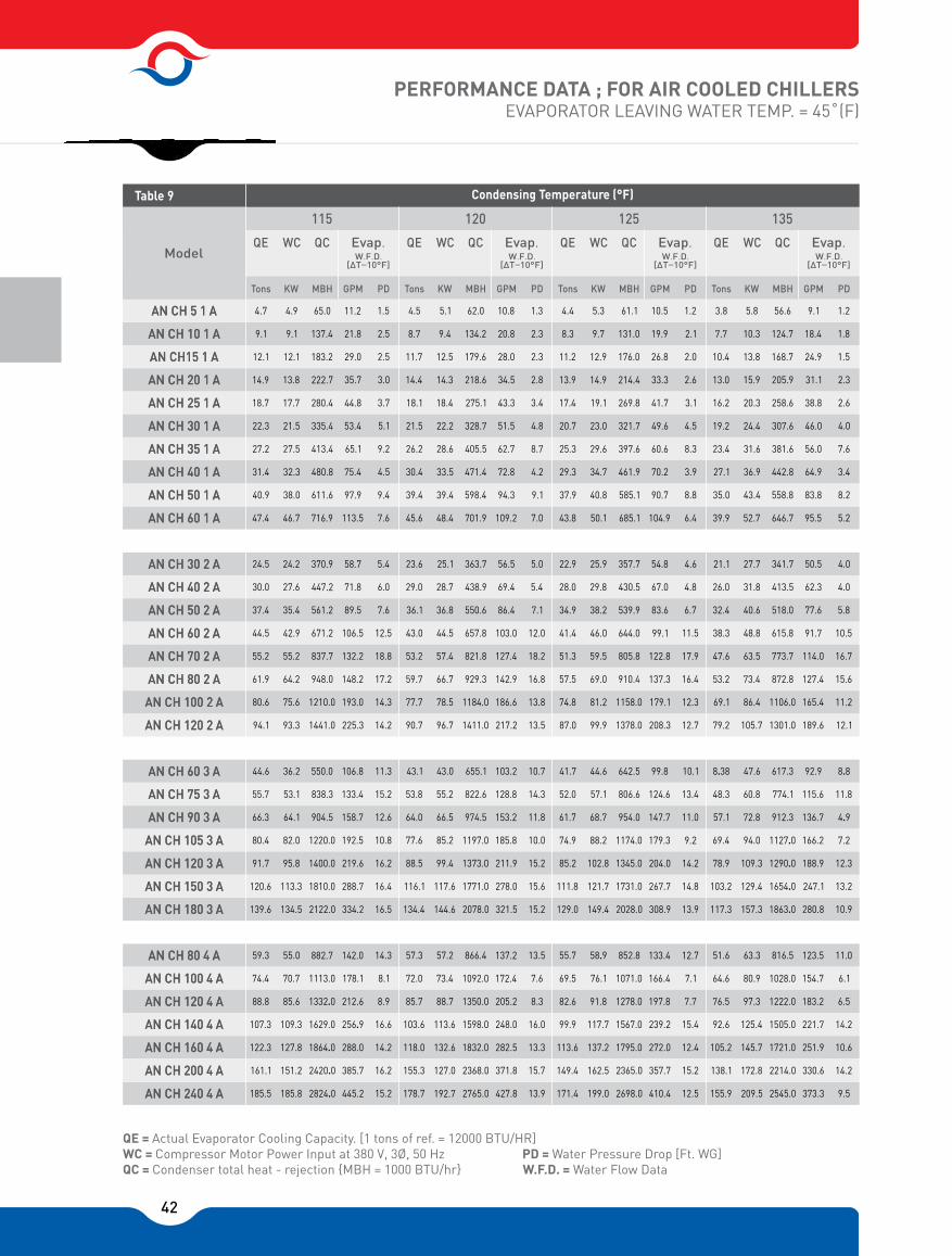
42
PERFORMANCE DATA ; FOR AIR COOLED CHILLERSEVAPORATOR LEAVING WATER TEMP. = 45˚(F)
QE = Actual Evaporator Cooling Capacity. [1 tons of ref. = 12000 BTU/HR]WC = Compressor Motor Power Input at 380 V, 3Ø, 50 Hz PD = Water Pressure Drop [Ft. WG] QC = Condenser total heat - rejection {MBH = 1000 BTU/hr} W.F.D. = Water Flow Data
4.7 4.5 4.4 3.81.5 1.3 1.2 1.2
7.6 7.0 6.4 5.2
9.4 9.1 8.8 8.2
4.5 4.2 3.9 3.4
9.2 8.7 8.3 7.6
5.1 4.8 4.5 4.0
3.7 3.4 3.1 2.6
3.0 2.8 2.6 2.3
2.5 2.3 2.0 1.5
2.5 2.3 2.1 1.8
4.9 5.1 5.3 5.810.5 9.1
23.6 22.9 21.125.1 25.9 27.75.0 4.6 4.024.5
44.6
59.3 57.3 55.7 51.6 63.358.955.0 57.2
41.7 8.38 92.947.643.1 43.0 44.611.3
14.3 13.5 12.7 11.0
10.7 10.1 8.8
16.5
15.2 13.9 12.5 9.5
15.2 13.9 10.9
16.4
16.2 15.7 15.2 14.2
15.6 14.8 13.2
16.2
14.2 13.3 12.4 10.6
15.2 14.2 12.3
10.8
16.6 16.0 15.4 14.2
10.0 9.2 7.2
12.6
8.9 8.3 7.7 6.5
11.8 11.0 4.9
15.2
8.1 7.6 7.1 6.1
14.3 13.4 11.8
36.2 106.8
142.0 137.2 133.4 123.5
103.2 99.8
5.4
6.0
7.6
12.5
18.8
17.2
14.3
14.2 90.7 87.0 79.296.7 99.9 105.713.5 12.7 12.194.1
77.7 74.8 69.178.5 81.2 86.413.8 12.3 11.280.6
139.6
185.5 178.7 171.4 155.9 209.5199.0185.8 192.7
129.0 117.3 280.8157.3134.4 144.6 149.4134.5 334.2
445.2 427.8 410.4 373.3
321.5 308.9
59.7 57.5 53.266.7 69.0 73.416.8 16.4 15.661.9
120.6
161.1 155.3 149.4 138.1 172.8162.5151.2 127.0
111.8 103.2 247.1129.4116.1 117.6 121.7113.3 288.7
385.7 371.8 357.7 330.6
278.0 267.7
53.2 51.3 47.657.4 59.5 63.518.2 17.9 16.755.2
91.7
122.3 118.0 113.6 105.2 145.7
125.4
137.2127.8 132.6
85.2 78.9 188.9109.388.5 99.4 102.895.8 219.6
288.0 282.5 272.0 251.9
211.9 204.0
43.0 41.4 38.344.5 46.0 48.812.0 11.5 10.544.5
80.4
107.3 103.6 99.9 92.6117.7109.3 113.6
74.9 69.4 166.294.077.6 85.2 88.282.0 192.5
256.9 248.0 239.2 221.7
185.8 179.3
36.1 34.9 32.436.8 38.2 40.67.1 6.7 5.837.4
66.3
88.8 85.7 82.6 76.5 97.391.885.6 88.7
61.7 57.1 136.772.864.0 66.5 68.764.1 158.7
212.6 205.2 197.8 183.2
153.2 147.7
29.0 28.0 26.028.7 29.8 31.85.4 4.8 4.030.0
55.7
74.4 72.0 69.5 64.6 80.976.170.7 73.4
52.0 48.3 115.660.853.8 55.2 57.153.1 133.4
178.1 172.4 166.4 154.7
128.8 124.6
47.4 45.6 43.8 39.946.7
24.2
27.6
35.4
42.9
55.2
64.2
75.6
93.3
48.4 50.1 52.7104.9 95.5716.9
370.9
550.0
882.7 866.4 852.8 816.5
655.1 642.5 617.3
357.7 341.756.5 54.8 50.5363.7
1441.0 1378.0 1301.0217.2 208.3 189.61411.0
1210.0
2122.0
2824.0 2765.0 2698.0 2545.0
2078.0 2028.0 1863.0
1158.0 1106.0186.6 179.1 165.41184.0
948.0
1810.0
2420.0 2368.0 2365.0 2214.0
1771.0 1731.0 1654.0
910.4 872.8142.9 137.3 127.4929.3
837.7
1400.0
1864.0 1832.0 1795.0 1721.0
1373.0 1345.0 1290.0
805.8 773.7127.4 122.8 114.0821.8
671.2
1220.0
1629.0 1598.0 1567.0 1505.0
1197.0 1174.0 1127.0
644.0 615.8103.0 99.1 91.7657.8
561.2
904.5
1332.0 1350.0 1278.0 1222.0
1028.0
974.5 954.0 912.3
539.9 518.086.4 83.6 77.6550.6
447.2
838.3
1113.0 1092.0 1071.0
822.6 806.6 774.1
430.5 413.569.4 67.0 62.3438.9
701.9 685.1 646.7
65.0 62.0 61.1 56.6
137.4 134.2 131.0 124.7
183.2 179.6 176.0 168.7
222.7 218.6 214.4 205.9
280.4 275.1 269.8 258.6
335.4 328.7 321.7 307.6
413.4 405.5 397.6 381.6
480.8 471.4 461.9 442.8
611.6 598.4 585.1 558.840.9 39.4 37.9 35.038.0 39.4 40.8 43.490.7 83.8
31.4 30.4 29.3 27.132.3 33.5 34.7 36.970.2 64.9
27.2 26.2 25.3 23.427.5 28.6 29.6 31.660.6 56.0
22.3 21.5 20.7 19.221.5 22.2 23.0 24.449.6 46.0
18.7 18.1 17.4 16.217.7 18.4 19.1 20.341.7 38.8
14.9 14.4 13.9 13.013.8 14.3 14.9 15.933.3 31.1
113.5
58.7
71.8
89.5
106.5
132.2
148.2
193.0
225.3
109.2
97.9 94.3
75.4 72.8
65.1 62.7
53.4 51.5
44.8 43.3
35.7 34.5
29.0 28.0
21.8 20.8
11.2 10.8
12.1 11.7 11.2 10.412.1 12.5 12.9 13.826.8 24.9
9.1 8.7 8.3 7.79.1 9.4 9.7 10.319.9 18.4
Table 9
Model
AN CH 5 1 A
AN CH 10 1 A
AN CH15 1 A
AN CH 20 1 A
AN CH 30 1 A
AN CH 35 1 A
AN CH 40 1 A
AN CH 50 1 A
AN CH 60 1 A
AN CH 30 2 A
AN CH 40 2 A
AN CH 50 2 A
AN CH 60 2 A
AN CH 70 2 A
AN CH 80 2 A
AN CH 100 2 A
AN CH 120 2 A
AN CH 60 3 A
AN CH 75 3 A
AN CH 90 3 A
AN CH 105 3 A
AN CH 120 3 A
AN CH 150 3 A
AN CH 180 3 A
AN CH 80 4 A
AN CH 100 4 A
AN CH 120 4 A
AN CH 140 4 A
AN CH 160 4 A
AN CH 200 4 A
AN CH 240 4 A
AN CH 25 1 A
AN CH 5 1 A
AN CH 10 1 A
AN CH15 1 A
AN CH 20 1 A
AN CH 30 1 A
AN CH 35 1 A
AN CH 40 1 A
AN CH 50 1 A
AN CH 60 1 A
AN CH 30 2 A
AN CH 40 2 A
AN CH 50 2 A
AN CH 60 2 A
AN CH 70 2 A
AN CH 80 2 A
AN CH 100 2 A
AN CH 120 2 A
AN CH 60 3 A
AN CH 75 3 A
AN CH 90 3 A
AN CH 105 3 A
AN CH 120 3 A
AN CH 150 3 A
AN CH 180 3 A
AN CH 80 4 A
AN CH 100 4 A
AN CH 120 4 A
AN CH 140 4 A
AN CH 160 4 A
AN CH 200 4 A
AN CH 240 4 A
AN CH 25 1 A
Condensing Temperature (°F)
115 120 125 135
QCWCQE
Tons KW MBH GPM PD
Evap.W.F.D.
�T=10°F]
QC QC QCWC WC WCQE QE QE
Tons Tons TonsKW KW KWMBH MBH MBHGPM GPM GPMPD PD PD
Evap.W.F.D.
�T=10°F]
Evap.W.F.D.
�T=10°F]
Evap.W.F.D.
�T=10°F]

43
TECHNICAL DATA
Note:LRA : Locked Rotor Amps MOC : Maximum Operating Current FLA : Full Load Amps RLA : Rated Load Amps* Suggested cabel size based on copper conductor under full load conditions (FLA) at maximum ambient temperature of 50 C and maximum distance of 70m.** Excluding the amount of refrigerant for an air cooled condenser & relevant pipings.
Two Compressor Models
75.755.850.837.132.225.722.9
85.763.758.242.636.629.226.4
10791.671.862.447.740.130.528.8
544444347284218192160129
93.47766.255.843.83627.823.8
177.2147109.899.673.26350.643.6
4*16
4*16
4*16
6050403530252015
23502200214019101690145013701210
9379.466.85243.233.629.6
171.4127.4116.485.273.258.452.8
3*95/50
3*95/50
3*70/35
3*70/35
3*50/25
3*35/16
3*50/25
3*50/25
3*25/16
3*25/16
3*25/16
3*25/16
3024211815129
90.4
103.2
112.2
206.4
3*120/70
36
18101750169015001380120011501010
44 42.2 2.22.222
79.165.948.343.731.827.822.219
88.673.554.949.836.631.525.321.8
AN CH 5 1 AN CH 10 1 AN CH 15 1 AN CH 20 1 AN CH 25 1 AN CH 30 1 AN CH 35 1 AN CH 40 1 AN CH 50 1 AN CH 60 1
6050403530252015105
Oil Charge(U.S Gals)
Ref. Charge**(Kg)
WaterCooled
90.475.755.850.837.132.27.5
103.285.763.758.242.636.68.4
10791.671.862.447.740.19
54444434728421819255
46.738.533.127.921.9183.8
88.673.554.949.836.631.57.2
3*35/16
3*25/16
30252017.51512.52.5
1585138012201050970820360
56.146.539.733.42621.64.6
103.285.763.758.242.636.68.4
3*50/16
3*25/16
3*25/16
3*25/16
4*16
4*16
4*16
4*16
4*10
4*10
4*4
4*4
18151210.597.51.5
135011801110840810700
25.7
29.2
16.8
29.2
4*10
6
660
17.1
19.6
10.9
19.6
4*4
3
410
22.9
26.4
14.8
26.4
4*64.5
570310
2 2 21.11.1 1.1
30.5
160
1
21.3
121
1
28.8
129
10.5
79.165.948.343.731.827.86.5
88.673.554.949.836.631.5
13.9
25.3
10
770
4*10
22.2
25.3
8.8
16.3
5
460
4*4
14.3
16.3
11.9
21.8
7.5
6704*6
19
21.87.2
Table 10
Model
Single Compressor Models
AirCooled
WaterCooled
WaterCooled
WaterCooled
WaterCooled
WaterCooled
WaterCooled
WaterCooled
WaterCooled
WaterCooled
AirCooled
AirCooled
AirCooled
AirCooled
AirCooled
AirCooled
AirCooled
AirCooled
AirCooled
Elec
tric
al D
ata
Syst
emCo
mpr
esso
r M
otor
( Per
Uni
t )
HP
RLA
MOC
LRA
MaxKW Input
Wire*Size
FLA
FLA
Phys
ical
Dat
a
Oper. Weight (Kg)
6050403530252015
Oil Charge(U.S Gals)
Ref. Charge**(Kg)
WaterCooled
Table 11
Model Air
Cooled
Elec
tric
al D
ata
Syst
emCo
mpr
esso
r M
otor
( Per
Uni
t )
HP
RLA
MOC
LRA
MaxKW Input
Wire*Size
FLA
FLA
Phys
ical
Dat
a
Oper. Weight (Kg)
AN CH 30 2 AN CH 40 2 AN CH 50 2 AN CH 60 2 AN CH 70 2 AN CH 80 2 AN CH 100 2 AN CH 120 2
WaterCooled
WaterCooled
WaterCooled
WaterCooled
WaterCooled
WaterCooled
WaterCooled
AirCooled
AirCooled
AirCooled
AirCooled
AirCooled
AirCooled
AirCooled
TwoCompressor Models

44
TECHNICAL DATA
Note:LRA: Locked Rotor Amps MOC: Maximum Operating Current FLA: Full Load Amps RLA: Rated Load Amps* Suggested cabel size based on copper conductor under full load conditions (FLA) at maximum ambient temperature of 50˚C and maximum distance of 70m.** Excluding the amount of refrigerant for an air cooled condenser & relevant pipings.
Four Compressor Models
25.7 32.2 37.1 50.8 55.8 75.7 90.4
25.7 32.2 37.1 50.8 55.8 75.7 90.4
29.2 36.6 42.6 58.2 63.7 85.7 103.2
29.2 36.6 42.6 58.2 63.7 85.7 103.2
30.5 40.1 47.7 62.4 71.8 91.6 107
30.5 40.1 47.7 62.4 71.8 91.6 107
160 192 218 284 347 444 544
160 192 218 284 347 444 544
41.7 54 65.7 83.7 99.3 115.5 140.1
55.6 72 87.6 111.6 132.4 154 186.8
75.9 94.5 109.8 149.4 164.7 220.5 265.8
101.2 126 146.4 199.2 219.6
3*50
/25
3*50
/25
3*70
/35
3*70
/35
3*70
/35
3*12
0/70
3*15
0/70
3*18
5/95
3*24
0/12
0
30 37.5 45 52.5 60 75 90
40 50 60 70 80 100 120
1890 2160 2500 2880 2980 3100 3280
2570 3000 3200 3680 3880 4100 4350
50.4 64.8 78 100.2 119.1 139.5 168.3
67.2 86.4 104 133.6 158.8 186 224.4
87.6 109.8 127.8 174.6 191.1 257.1 309.6
116.8 146.4 170.4 232.8 254.8 340.8
3*25
/16
3*35
/16
3*95
/50
3*95
/50
3*15
0/70
3*18
5/95
3*35
/16
3*50
/25
3*50
/25
3*70
/35
3.90
/50
3*12
0/70
3*18
5/95
3*24
0/12
0
3*95
/50
3*18
5/95
3*18
5/95
3*24
0/12
0
3*30
0/15
0
18 22.5 27 31.5 36 45 54
24 30 36 42 48 60 72
1550 1750 2000 2250 2350 2470 2630
2150 2450 2600 2900 3100 3300 3550
3 3.3 3.3 3.3 6 66
4 4.44.4 4.4 88 8
22.2 27.8 31.8 43.7 48.3 65.9 79.1
22.2 27.8 31.8 43.7 48.3 65.9 79.1
25.3 31.5 36.6 49.8 54.9 73.5 88.6
25.3 31.5 36.6 49.8 54.9 73.5 88.6
AN CH 60 3 AN CH 75 3 AN CH 90 3 AN CH 105 3 AN CH 120 3 AN CH 150 3 AN CH 180 3
60504035302520
Oil Charge(U.S Gals)
Ref. Charge**(Kg)
WaterCooled
Table 12
Model
Three Compressor Models
AirCooled
Elec
tric
al D
ata
Syst
emCo
mpr
esso
r M
otor
( Per
Uni
t )
HP
RLA
MOC
LRA
MaxKW Input
Wire*Size
FLA
FLA
Phys
ical
Dat
a
Oper. Weight (Kg)
Table 13
WaterCooled
WaterCooled
WaterCooled
WaterCooled
WaterCooled
WaterCooled
AirCooled
AirCooled
AirCooled
AirCooled
AirCooled
AirCooled
AN CH 80 4 AN CH 100 4 AN CH 120 4 AN CH 140 4 AN CH 160 4 AN CH 200 4 AN CH 240 4
60504035302520
Oil Charge(U.S Gals)
Ref. Charge**(Kg)
WaterCooled
Model Air
Cooled
Elec
tric
al D
ata
Syst
emCo
mpr
esso
r M
otor
( Per
Uni
t )
HP
RLA
MOC
LRA
MaxKW Input
Wire*Size
FLA
FLA
Phys
ical
Dat
a
Oper. Weight (Kg)
WaterCooled
WaterCooled
WaterCooled
WaterCooled
WaterCooled
WaterCooled
AirCooled
AirCooled
AirCooled
AirCooled
AirCooled
AirCooled
292.8292.8252

45
Note: All Dimensions in mm
Recommended Service Area
5-1 10-1 15-1 20-1 25-1 30-1 35-1 40-1 50-1 60-1
A 1500 1500 1800 1800 2300 2300 2300 2300 2300 2300
Model
Table 14
30-2 40-2 50-2 60-2 70-2 80-2 100-2 120-2
A 2300 2300 2300 2700 2700 2700 2700 2700
Model
Table 14
30-2 40-2 50-2 60-2 70-2 80-2 100-2 120-2
A 2300 2300 2300 2700 2700 2700 2700 2700
Model
Table 14
60-3 75-3 90-3 105-3 70-2 120-3 150-3 180-3
A 2800 2800 3300 3000 3300 3300 3300 3800
Model
Table 14
80-4 100-4 120-4 140-4 160-4 200-4 240-4
A 3300 3300 3300 3300 3300 3800 4300
Model
Table 14
1000
A
1000
1000

46

47
48
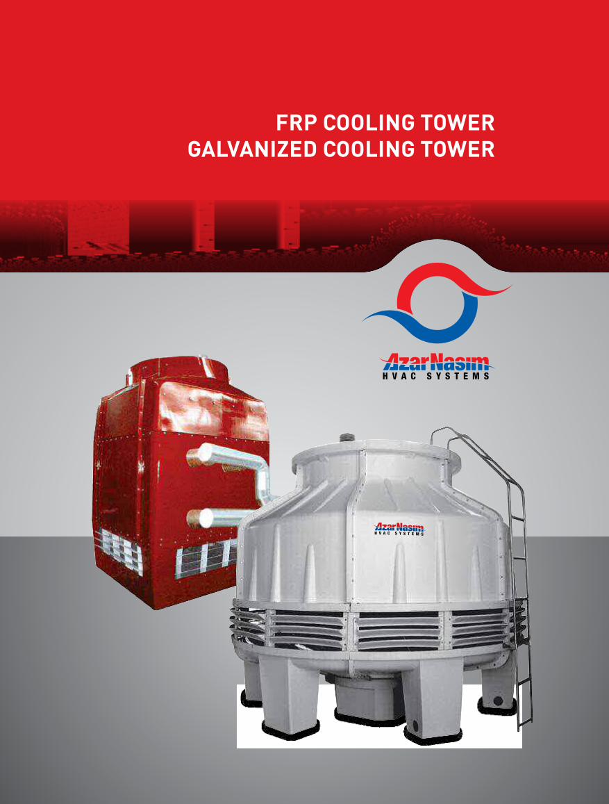
49
R CLI ER LIED CLI ER

50
1. Definition:Cooling towers are heat removal devices used to transfer process waste heat to the atmosphere. Cooling towers may either use the evaporation of water to remove process heat and cool the working fluid to near the wet-bulb air temperature or in the case of "Close Circuit Dry Cooling Towers" rely solely on air to cool the working fluid to near the dry-bulb air temperature. Common applications include cooling the circulating water used in oil refineries, chemical plants, power stations and building cooling. The towers vary in size from small roof-top units to very large hyperboloid structures that can be up to 200 meters tall and 100 meters in diameter or rectangular structures that can be over 40 meters tall and 80 meters long. Smaller towers are normally factory-built, while larger ones are constructed on site. They are often associated with nuclear power plants in popular culture, although cooling towers are constructed on many types of buildings.
2. Classification by use:
HVACAn HVAC (Heating, Ventilating, and Air Conditioning) cooling tower is a subcategory rejecting heat from a chiller. Watercooled chillers are normally more energy efficient than air-cooled chillers due to heat rejection to tower water at or near wet-bulb temperatures. Air-cooled chillers must reject heat at the dry-bulb temperature, and thus have lower average reverse-Carnot cycle effectiveness. Large office buildings, hospitals, and schools typically use one or more cooling towers as part of their air conditioning systems. Generally, industrial cooling towers are much larger than HVAC towers.
Industrial cooling towersIndustrial cooling towers can be used to remove heat from various sources such as machinery or heated process material.
The primary use of large, industrial cooling towers is to remove the heat absorbed in the circulating cooling water systems used in power plants, petroleum refineries, petrochemical plants, natural gas processing plants, food processing plants, semiconductor plants, and for other industrial facilities such as in condensers of distillation columns, for cooling liquid in crystallization, etc. The world's tallest cooling tower is the 200 meter tall cooling tower of Niederaussem Power Station.
3. Heat transfer methodsWith regard to the heat transfer mechanism employed, the main types are:Wet cooling towers or simply open circuit cooling towers operate on the principle of evaporation. The working fluid and the evaporated fluid (usually H2O) are one and the same. Dry Cooling Towers operate by heat transfer through a surface that separates the working fluid from ambient air, such as in a tube to air heat exchanger, utilizing convective heat transfer. They do not use evaporation.
4. Air flow generation methodsWith regard to drawing air through the tower, there are three types of cooling towers:Natural draft, which utilizes buoyancy via a tall chimney. Warm, moist air naturally rises due to the density difference to the dry, cooler outside air. Warm moist air is less dense than drier air at the same pressure. This moist air buoyancy produces a current air through the tower. Mechanical draft, which uses power driven fan motors to force or draw air through the tower. Induced draft: A mechanical draft tower with a fan at the discharge which pulls air through tower. The fan induces hot moist air out the discharge. This produces low entering and high exiting air velocities, reducing the possibility of recirculation in which discharged air flows back into the air intake. This fan/fin arrangement is also known as draw-through.Forced draft: A mechanical draft tower with a
FRP AND GALVANIZED COOLING TOWER
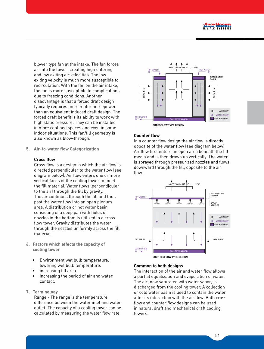
51
blower type fan at the intake. The fan forces air into the tower, creating high entering and low exiting air velocities. The low exiting velocity is much more susceptible to recirculation. With the fan on the air intake, the fan is more susceptible to complications due to freezing conditions. Another disadvantage is that a forced draft design typically requires more motor horsepower than an equivalent induced draft design. The forced draft benefit is its ability to work with high static pressure. They can be installed in more confined spaces and even in some indoor situations. This fan/fill geometry is also known as blow-through.
5. Air-to-water flow Categorization
Cross flow Cross flow is a design in which the air flow is directed perpendicular to the water flow (see diagram below). Air flow enters one or more vertical faces of the cooling tower to meet the fill material. Water flows (perpendicular to the air) through the fill by gravity. The air continues through the fill and thus past the water flow into an open plenum area. A distribution or hot water basin consisting of a deep pan with holes or nozzles in the bottom is utilized in a cross flow tower. Gravity distributes the water through the nozzles uniformly across the fill material.
6. Factors which effects the capacity of cooling tower
• Environment wet bulb temperature: lowering wet bulb temperature.
• increasing fill area.• increasing the period of air and water
contact.
7. TerminologyRange - The range is the temperature difference between the water inlet and water outlet. The capacity of a cooling tower can be calculated by measuring the water flow rate
Counter flowIn a counter flow design the air flow is directly opposite of the water flow (see diagram below) Air flow first enters an open area beneath the fill media and is then drawn up vertically. The water is sprayed through pressurized nozzles and flows downward through the fill, opposite to the air flow.
Common to both designsThe interaction of the air and water flow allows a partial equalization and evaporation of water. The air, now saturated with water vapor, is discharged from the cooling tower. A collection or cold water basin is used to contain the water after its interaction with the air flow. Both cross flow and counter flow designs can be used in natural draft and mechanical draft cooling towers.
MOIST, WARM AIR OUT FANHOT WATER
IN
DISTRIBUTION BASIN
DR
Y A
IR IN
DR
Y A
IR IN
COLD WATER OUT COLLECTION BASIN
AIR FLOW
WATER FLOW
FILL MATERIAL
CROSSFLOW TYPE DESIGN
HOT WATER IN
DISTRIBUTIONSYSTEM
SPRAY NOZZLES
COUNTERFLOW TYPE DESIGN
AIR FLOW
WATER FLOW
FILL MATERIAL
FANMOIST, WARM AIR OUT
HOT WATER IN
COLD WATER OUT
DRY AIR IN
COLLECTION BASIN
DRY AIR IN
52
and the range from below equation:
Cooling tower load (KW) = flow rate (L/S) ×4.19 (Kj/KgºK)×Range(ºK)
Approach - The approach is the difference in temperature between the cooled-water temperature and the entering-air wet bulb temperature (twb). Since the cooling towers are based on the principles of evaporative cooling, the maximum cooling tower efficiency depends on the wet bulb temperature of the air. The wet-bulb temperature is a type of temperature measurement that reflects the physical properties of a system with a mixture of a gas and a vapor, usually air and water vapor.
8. Principal of operations of "Tahvieh Azar Nasim" conical Type Cooling Towers
The automatic rotating sprinkler system distributes the hot water evenly over the entire fill section. Dry air is simultaneously drafted upward causing evaporation and so, the heat is removed. The cooled water falls into the basin and is pumped to the heat source for recirculation.
9. Thermal DesignThe "Tahvieh Azar Nasim" cooling towers operate on the counter flow principle which gives the best performances. The air flow through the tower fill is opposed the water flow. The cold air meets the closed water at the bottom of the fill providing maximum evaporation and heat transfer in the fill. The PVC fill is corrugated with clear channels between flutes to prevent any blockage and giving a large surface area per unit volume. Water flows through the fill in a thin film exposed the maximum area to the cooling air flow. The flutes of the fill area at an angle and each layer of fill section are reversed, turning the film or water and air over for maximum cooling.
10. Better Air FlowThe rotating water sprinkler head distributes the hot water which forming a fine spray,
and hence does not need the conventional type of moisture eliminator. This is because the water header has large number of holes giving a �steam� type flow direct into the fill. Tower with fixed nozzles cannot obtain the coverage, which is needed for optimum cooling. We should not overlook that in rectangular type towers, eliminators provide a pressure drop which evens out the flow particularity into the corner.The "Tahvieh Azar Nasim" cooling tower being round, plus its conical fan inlet can better provide an even air flow through the fill, with a lower pressure drop, and without the additional pressure drop caused by the eliminator needed on other towers. Fan KW depends on the mass of air delivered, the pressure generated and the blade efficiency, from the available data on other manufacturers' tower. �Tahvieh Azar Nasim� air volumes are similar to competitor�s size. The influence factors for lower power are �pressure� and �efficiency�. Tower has large air inlet area, with low air velocity; low pressure drop tower is of the induced draft type. The fan is in the ideal position, to discharge the air at a high velocity upwards and allow natural convection to prevent recirculation, as can happen with the forced draft tower arrangement, where air leaves the eliminator at low velocity.
11. Pumping headAs seen already, the water distribution by a rotating header is a significant part of the �Tahvieh Azar Nasim� tower design. The large diameter holes in the rotating header give a gentle stream of water at negligible pressure lose. Also, there is no risk of �clogging�, as can easily happen with spray nozzles in other types of towers. The �Tahvieh Azar Nasim� cooling towers pumping head, is the static height of the spray or header pipe above the water level in basin, plus the pressure loss the rotating header, sprays of balancing valves, according to the type of tower being considered. It should be noted
53
that pumping heads quoted for �Tahvieh Azar Nasim� towers include both of these as well as piping inside the pressure loss of sprays is usually quoted. To this must be added the static lift to the spray header from the basic required for a �Tahvieh Azar Nasim� cooling tower 50% less than for some other cooling towers.
12. Lift factorAlthough we generally refer to the towers as being constructed of fiberglass, we should actually refer to them as being FRP (Fiberglass Reinforced Plastic) should not be confused with the translucent fiberglass roofing panels, and in particular with the cheaper grades which have given poor results even only in a few years. Without an adequate protective layer, the sun�s ultra violet rays draw the fibers upwards so that �hairs� appear to be growing on the panels as with fiberglass hulls, the �Tahvieh Azar Nasim� towers do not need painting. However, if a client wishes to have color scheme changed, painting is possible.Compared with timber towers which will ultimately rot, or steel towers which will rust despite increased maintenance, the fiberglass tower has tremendous financial advantages for the wise investor. Unfortunately, many buyers appear to be only concerned to maintenance, running costs or rate of deterioration.
13. Smaller Fan MotorsSmaller electric motor in "Tahvieh Azar Nasim "cooling towers, causes lower consumption power and save money.
14. Advantages of "Tahvieh Azar Nasim" Cooling Towers:
• Strong FRP layers used isophetalic resin, no vibration and increase the life of cooling tower.
• Neopentyl glycol (NPG) anti-UV causes long lasting color, decorative and long life.
• FRP sump• Fill are made of Virgin antibacterial PVC
films.• Fans are dynamically balanced for
smooth operation, longer bearing life including that of the supporting structure.
• The fan drive motor is in IP-55, �F� class.• 5years warranty insures you a right
purchase.
15. ComponentsThe various components of FRP conical type cooling tower are as below:
CasingThe bolt together FRP casing is completely non-corrosive. The casing enclosed the PVC fills services to isolate the air stream, which passes over the fills. The casing is conical shaped to reduce frictional resistance of air and aids flow pattern. It is designed to withstand wind loads up to 75km/hr., and vibrations emanating from the motor and other equipment. FRP casing has a high impact resistance when laminated with Isophetalic Resin and even if damaged is easily repaired at site. The neopentyl glycol gel coat is U.V. inhibited to provide a long lasting finished appearance and service life and imported wax release agents helps retain colors for long periods even if exposed to direct sunlight. The casing is in sections of easy to handle sizes and is assembled at site using bolting joints. The conical shape of casing is ideal with regard to cooling efficiency and space economy.
BasinThe basin serves the purposes of collecting the water descending from the fills and channeling it to the suction point. Further the basin also acts as a reservoir of water. The basin is also made of FRP and has similar characteristic the same as casing.
SumpThe sump is located below and in the center of the basin and has all connections for inlet/
54
outlet, drain, filling and overflow. The unit is at the lowest point and is always flooded and thus ensuring no capitations on the pump suction. The suction tank is fully molded in FRP to prevent corrosion and subsequent leakages. A drain is provided to the tank which makes it quite simple to remove the accumulated dirt and to drain out the water, simplifies the cleaning and maintenance of the tower.
Tower StructureThe structure of the tower supports the casing, basin and motor mounting loads to the foundations. These are of MS and are hot dipped galvanized so as to resist corrosion.
FillsThe fills section is designed to bring about intimate contact of water and air so as to facilitate heat and mass transfer at the same time aiding in proper and even distribution of air and water over the cross section, while maintaining minimum pressure drop. The fills are of honeycomb section and are vacuum formed from anti-bacterial Virgin PVC for excellent resistance to corrosion and give maximum area for intake.
SprinklerThe gravity die cast aluminum alloy / S.S sprinkler is used to distribute the water evenly over the cross section of the tower. An aluminum alloy / S.S rotary head with radial PVC / PP pipes having drilled holes serves this purpose. The rotation of assembly is accomplished due to reaction of water jet being sprayed from PVC / PP pipes. The sprinkler head is mounted on top of the central water supply. To ensure free rotation even at low flows the sprinkler has 2 sealed pre lubricated ball bearing mounted on the central shaft. This sprinkler system is preferred over the fixed nozzle system forVarious reasons.
Fan / Fan BladesThe light weight fan has good corrosion-
resistant quality is an axial flow, multi blade version with adjustable blade pitch. The fan is designed to deliver large volumes of air at low power consumption and low noise generation. The fans are dynamically balanced for smooth operation, longer bearing life including that of the supporting structure. FRP fan blades may also be provided on demand and these have in addition to excellent corrosion-resistance, good noise reduction properties.
Fan Drive MotorThe fan drive motor is in IP-55 �F� class design. The fan is directly driven by the special extended shaft motor made from steel mounted facing downward on a mounting frame on the top of the Cooling Tower.
LouversFRP louvers are installed at the air inlet (space between the Tower casing and water Basin) to prevent water splash and contaminants like leaves, bird etc. entering the Cooling Tower.
GrillsSince Cooling Tower are generally installed on windswept rooftop or higher altitude, galvanized MS grill are installed at the air outlet to prevent contaminants like leaves, bird etc. entering the cooling tower.
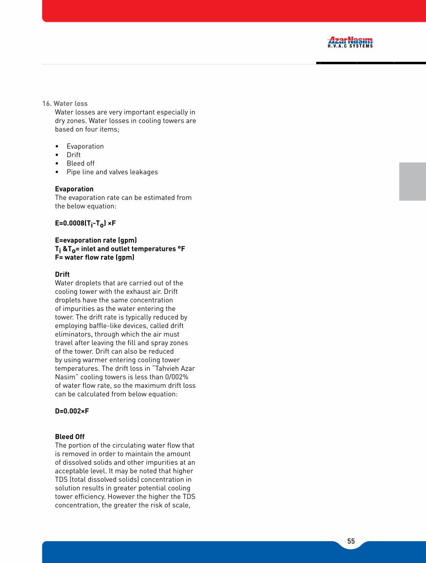
55
16. Water lossWater losses are very important especially in dry zones. Water losses in cooling towers are based on four items;
• Evaporation• Drift• Bleed off• Pipe line and valves leakages
EvaporationThe evaporation rate can be estimated from the below equation:
E=0.0008(Ti-To) ×F
E=evaporation rate (gpm)Ti &To= inlet and outlet temperatures °FF= water flow rate (gpm)
DriftWater droplets that are carried out of the cooling tower with the exhaust air. Drift droplets have the same concentration of impurities as the water entering the tower. The drift rate is typically reduced by employing baffle-like devices, called drift eliminators, through which the air must travel after leaving the fill and spray zones of the tower. Drift can also be reduced by using warmer entering cooling tower temperatures. The drift loss in �Tahvieh Azar Nasim� cooling towers is less than 0/002% of water flow rate, so the maximum drift loss can be calculated from below equation:
D=0.002×F
Bleed OffThe portion of the circulating water flow that is removed in order to maintain the amount of dissolved solids and other impurities at an acceptable level. It may be noted that higher TDS (total dissolved solids) concentration in solution results in greater potential cooling tower efficiency. However the higher the TDS concentration, the greater the risk of scale,
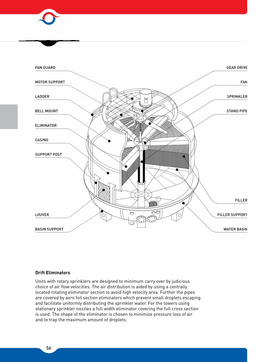
56
Drift Eliminators
GEAR DRIVE
FAN
SPRINKLER
STAND PIPE
FILLER
FILLER SUPPORT
WATER BASIN
FAN GUARD
MOTOR SUPPORT
LADDER
BELL MOUNT
ELIMINATOR
CASING
SUPPORT POST
LOUVER
BASIN SUPPORT
Units with rotary sprinklers are designed to minimum carry over by judicious choice of air flow velocities. The air distribution is aided by using a centrally located rotating eliminator section to avoid high velocity area. Further the pipes are covered by aero foil section eliminators which prevent small droplets escaping and facilitate uniformly distributing the sprinkler water. For the towers using stationary sprinkler nozzles a full width eliminator covering the full cross section is used. The shape of the eliminator is chosen to minimize pressure loss of air and to trap the maximum amount of droplets.
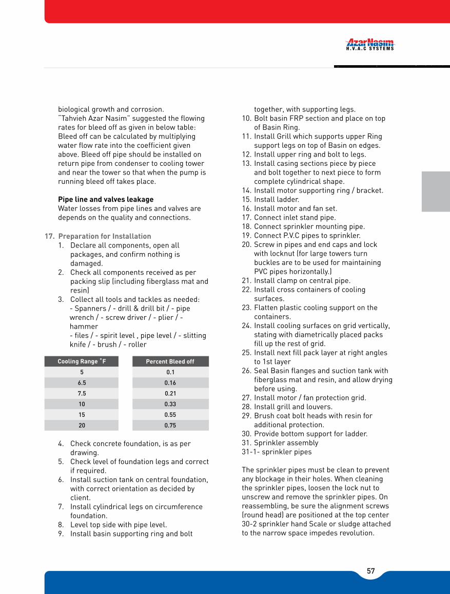
57
biological growth and corrosion.�Tahvieh Azar Nasim� suggested the flowing rates for bleed off as given in below table:Bleed off can be calculated by multiplying water flow rate into the coefficient given above. Bleed off pipe should be installed on return pipe from condenser to cooling tower and near the tower so that when the pump is running bleed off takes place.
Pipe line and valves leakage Water losses from pipe lines and valves are depends on the quality and connections.
17. Preparation for Installation1. Declare all components, open all
packages, and confirm nothing is damaged.
2. Check all components received as per packing slip (including fiberglass mat and resin)
3. Collect all tools and tackles as needed:- Spanners / - drill & drill bit / - pipe wrench / - screw driver / - plier / - hammer - files / - spirit level , pipe level / - slitting knife / - brush / - roller
4. Check concrete foundation, is as per drawing.
5. Check level of foundation legs and correct if required.
6. Install suction tank on central foundation, with correct orientation as decided by client.
7. Install cylindrical legs on circumference foundation.
8. Level top side with pipe level.9. Install basin supporting ring and bolt
together, with supporting legs.10. Bolt basin FRP section and place on top
of Basin Ring.11. Install Grill which supports upper Ring
support legs on top of Basin on edges.12. Install upper ring and bolt to legs.13. Install casing sections piece by piece
and bolt together to next piece to form complete cylindrical shape.
14. Install motor supporting ring / bracket.15. Install ladder.16. Install motor and fan set.17. Connect inlet stand pipe.18. Connect sprinkler mounting pipe.19. Connect P.V.C pipes to sprinkler.20. Screw in pipes and end caps and lock
with locknut (for large towers turn buckles are to be used for maintaining PVC pipes horizontally.)
21. Install clamp on central pipe.22. Install cross containers of cooling
surfaces.23. Flatten plastic cooling support on the
containers.24. Install cooling surfaces on grid vertically,
stating with diametrically placed packs fill up the rest of grid.
25. Install next fill pack layer at right angles to 1st layer
26. Seal Basin flanges and suction tank with fiberglass mat and resin, and allow drying before using.
27. Install motor / fan protection grid.28. Install grill and louvers.29. Brush coat bolt heads with resin for
additional protection.30. Provide bottom support for ladder.31. Sprinkler assembly31-1- sprinkler pipes
The sprinkler pipes must be clean to prevent any blockage in their holes. When cleaning the sprinkler pipes, loosen the lock nut to unscrew and remove the sprinkler pipes. On reassembling, be sure the alignment screws (round head) are positioned at the top center 30-2 sprinkler hand Scale or sludge attached to the narrow space impedes revolution.
Cooling Range �
5
6.5
7.5
10
15
20
Percent Bleed off
0.1
0.16
0.21
0.33
0.55
0.75
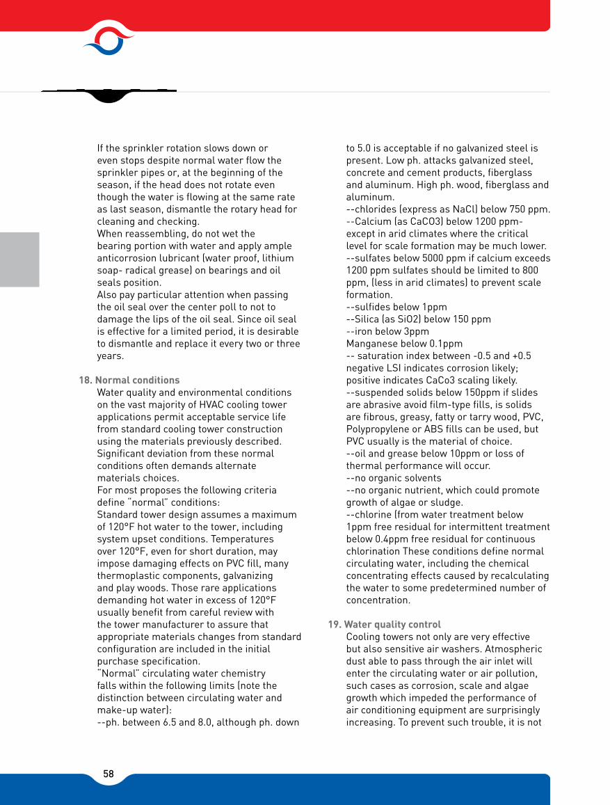
58
If the sprinkler rotation slows down or even stops despite normal water flow the sprinkler pipes or, at the beginning of the season, if the head does not rotate even though the water is flowing at the same rate as last season, dismantle the rotary head for cleaning and checking.When reassembling, do not wet the bearing portion with water and apply ample anticorrosion lubricant (water proof, lithium soap- radical grease) on bearings and oil seals position. Also pay particular attention when passing the oil seal over the center poll to not to damage the lips of the oil seal. Since oil seal is effective for a limited period, it is desirable to dismantle and replace it every two or three years.
18. Normal conditionsWater quality and environmental conditions on the vast majority of HVAC cooling tower applications permit acceptable service life from standard cooling tower construction using the materials previously described. Significant deviation from these normal conditions often demands alternate materials choices.For most proposes the following criteria define �normal� conditions:Standard tower design assumes a maximum of 120°F hot water to the tower, including system upset conditions. Temperatures over 120°F, even for short duration, may impose damaging effects on PVC fill, many thermoplastic components, galvanizing and play woods. Those rare applications demanding hot water in excess of 120°F usually benefit from careful review with the tower manufacturer to assure that appropriate materials changes from standard configuration are included in the initial purchase specification.�Normal� circulating water chemistry falls within the following limits (note the distinction between circulating water and make-up water):--ph. between 6.5 and 8.0, although ph. down
to 5.0 is acceptable if no galvanized steel is present. Low ph. attacks galvanized steel, concrete and cement products, fiberglass and aluminum. High ph. wood, fiberglass and aluminum.--chlorides (express as NaCl) below 750 ppm.--Calcium (as CaCO3) below 1200 ppm-except in arid climates where the critical level for scale formation may be much lower.--sulfates below 5000 ppm if calcium exceeds 1200 ppm sulfates should be limited to 800 ppm, (less in arid climates) to prevent scale formation.--sulfides below 1ppm--Silica (as SiO2) below 150 ppm--iron below 3ppmManganese below 0.1ppm-- saturation index between -0.5 and +0.5 negative LSI indicates corrosion likely; positive indicates CaCo3 scaling likely.--suspended solids below 150ppm if slides are abrasive avoid film-type fills, is solids are fibrous, greasy, fatty or tarry wood, PVC, Polypropylene or ABS fills can be used, but PVC usually is the material of choice.--oil and grease below 10ppm or loss of thermal performance will occur.--no organic solvents--no organic nutrient, which could promote growth of algae or sludge.--chlorine (from water treatment below 1ppm free residual for intermittent treatment below 0.4ppm free residual for continuous chlorination These conditions define normal circulating water, including the chemical concentrating effects caused by recalculating the water to some predetermined number of concentration.
19. Water quality controlCooling towers not only are very effective but also sensitive air washers. Atmospheric dust able to pass through the air inlet will enter the circulating water or air pollution, such cases as corrosion, scale and algae growth which impeded the performance of air conditioning equipment are surprisingly increasing. To prevent such trouble, it is not

59
enough to depend entirely upon chemical or equipment. Check the water quality and also on environment factors as well.
1. Make quality analysis of circulating water and supplementing water and take appropriate action to control the quality.
2. If when the trouble is anticipated owing to the condensed circulation water, we recommended the use of chemical, periodic below sown to keep the operation within the regulate water quality.
3. For nitrate and sediment, clean with chemicals.
4. Use strainer or filter depending on the water quality.
20. Post assembly Checks/Pre-commissioning Checks
1. Check level of sump, and fan ensure they are parallel to ground.
2. Check center pipe is vertical and sprinkler arms are all leveled, at right angles to center pipe.
3. Ensure no dirt/other foreign particles are present in sump, suction tank etc. sweep clean/wash clean.
4. Rotate sprinkler with hand and ensure it is free.
5. Ensure fill top is even.6. Ensure sprinkler arms are at a constant
level above the fills and that the arms do not rub against/ uneven fills, casing etc.
7. Ensure fan and motor assembly is free.
8. Check all bolts are tight and no loose part noticed.
9. Fill water in sump and check and eliminate water leaks.
10. Connect correct power (i.e. 380V, 50Hz 3PH.AC) supply to fan and check
a. Direction of rotation of fan is correct and air is being sucked through screen above sump and discharged vertically upwards.b. Vibrations are negligible.c. Fan cable connections are made with lugs & terminal cover gasket is tight.
11. Establish water flow and check sprinkler rotates and check any unregulated bypass from sprinkler pipes.
Check after commissioning1. Check motor speed to be as specified in
technical data for particular model.2. Check air flow rate is as per specification.3. Check water flow rate is as per
specification.4. Check power / current drawn by fan
motor are within limits and as specified.5. Check for abnormal noise / vibration
during operation.6. Check sprinkler rotates freely at 5 to
8 rpm or adjust holes to angle so as to achieve correct rpm.
7. Ensure water is being distributed evenly over the FRP eliminator plates and there is no carry over from below the eliminator plate water must fall down below evenly and not pass out.
8. Eliminator plate adjustment to be checked to ensure equal distance between fill top and plat bottom.
9. Measure temperature at following locations:
I. Water inletII. Water outlet / sumpIII. Make up water inletIV. Wet bulb / dry bulb temperature at outlet
WARNINGWater treatment must be supplied and / or applied by a professional in the field in order to avoid fill damage. It is the user�s / owner�s responsibility to treat water in order to stop biological contaminants and avoid among other bacterium, the Legionella bacteria, which is known to cause legionnaire disease.

60
of tower above fan
10. Adjust drain valve to give adequate blow down.
11. Set float to ensure proper operation and to avoid over flow when plant stops.
Maintenance Schedule
Every DayCheck if--1. Vibrations are normal / noise normal.2. Proper Water distribution.3. Measuring every three phases of fan.4. Normal Inlet / outlet temperature of
waterEvery week:1. Clean inlet grill to remove entrained
matter.2. Clean inlet water filter.3. Clean sprinklers / nozzles if chocked.4. Check growth of Algae etc. and
remove from sump.5. Check belts stiffness.Every month:1. Drain tank, flush out and remove any
sediment.2. Check fills if clogged due to Allege,
sediment / salt, etc.3. Check structural / FRP casing and
Basin damages.4. Clean outside of the tower with
detergents like soap and water.5. Check and tighten all bolts.6. Grease bolts to facilitate easy opening
in future.Every two months:1. Grease all bearings of motor.2. Grease all bearings of sprinklers.3. Check run out on fan motor Shafer.4. Clean blades from foreign materials.5. Check conditioner plates if damaged
and replace it.
Replace bearings of sprinkler ssembly after 2 years and grease it.

61
After the inspection and troubleshooting process, contact the after sale services of Azar nasim co. otherwise, the problem shall be fixed by authorized personel.
Water �ow above specied Regulate to correct �ow rate
Water �ow below specied Adjust blade angle check and clean jail
Load higher than design Adjust load to correct level
Fill checked or coated Clean/replace lls. Use proper water (make up) quality
Fresh air intake not sufcient or area sufcient or area around tower not as specied
Improve ventilation and ensure exhaust air does not get recycled
WBT high Check design condition and ensure no recycling of exhaust air
Water bypassing lls Check sprinkler and distribution system
Sprinkler jammed/water not being sprinkler and distributed Repair sprinkler and distribution system
Filter chocked Clean water lter
Sprinkler pipes chocked Clean pipes and holes
Level of water low in pump Adjust �oat / inlet �ow ensure proper make up
Pump small Replace for correct �ow volume
Fan speed low Check bearings / motor
Fan blade angle in correct Correct blade angle required setting
Inlet grill chocked Clean air path
Sprinkler is rapid Adjust it
Filter chocked Clean or replace it
Eliminator is defective Replace or repair it
Fan mounting loose Tighten mounting bolt and correct/replace if needed
Fan block loose Tighten blade in hub
Fan unbalanced Rebalance and adjust
Motor bearing faulty Check and grease or replace bearing on motor
Hub mounting on motor shaft loose Tighten and use end plate and shims if needed
Many parts rubbing against tower components Give proper clearances and adjust/align components
Fuse burned due to damage contacts Fuse burned due to damage contacts
Insufcient switch capacity Insufcient switch capacity
Jammed Bearing Replace bearing
Too heavy load Lighten load proper level
a. lowering of voltage supply
b. unbalanced voltage supply
a. consult power company
b. consult power company
High surrounding temp Consult Azar Nasim
Contact between rotary and xed section Change bearing or supplement grease
Too much oil Lower the oil face to proper level
Loose bolt Tighten properly
Lowering of cooling capacity1- Motor
2- Sudden lowering of motor speed(rotation per minute)
3- Con not rev up motor speed(rotation per minute)
4- Fan stoppage
Temperature rise1- Motor getting over heated
Oil leaking , others1- In case of gear speed reducer oil leakage
Raise in discharging water temperature
Water �ow reduction
ir �ow reduction
Water splash
Noise and vibration
Electric blackout 1
Fuse burned due to damage contacts
Insufcient switch capacity
Bad switch contact
Electric blackout 1
Fuse burned due to damage contacts
Insufcient switch capacity
Defective starter / starter connection a. Correct connection according to name plateb. Check supply voltage across 3 phasesc. Check current in all 3 phases
Electric blackout 1
Fuse burned due to damage contacts
Insufcient switch capacity
Bad switch contact
Electric blackout 1
Fuse burned due to damage contacts
Insufcient switch capacity
Table 1 TROUBLESHOOTING
Trouble Cause Remedy
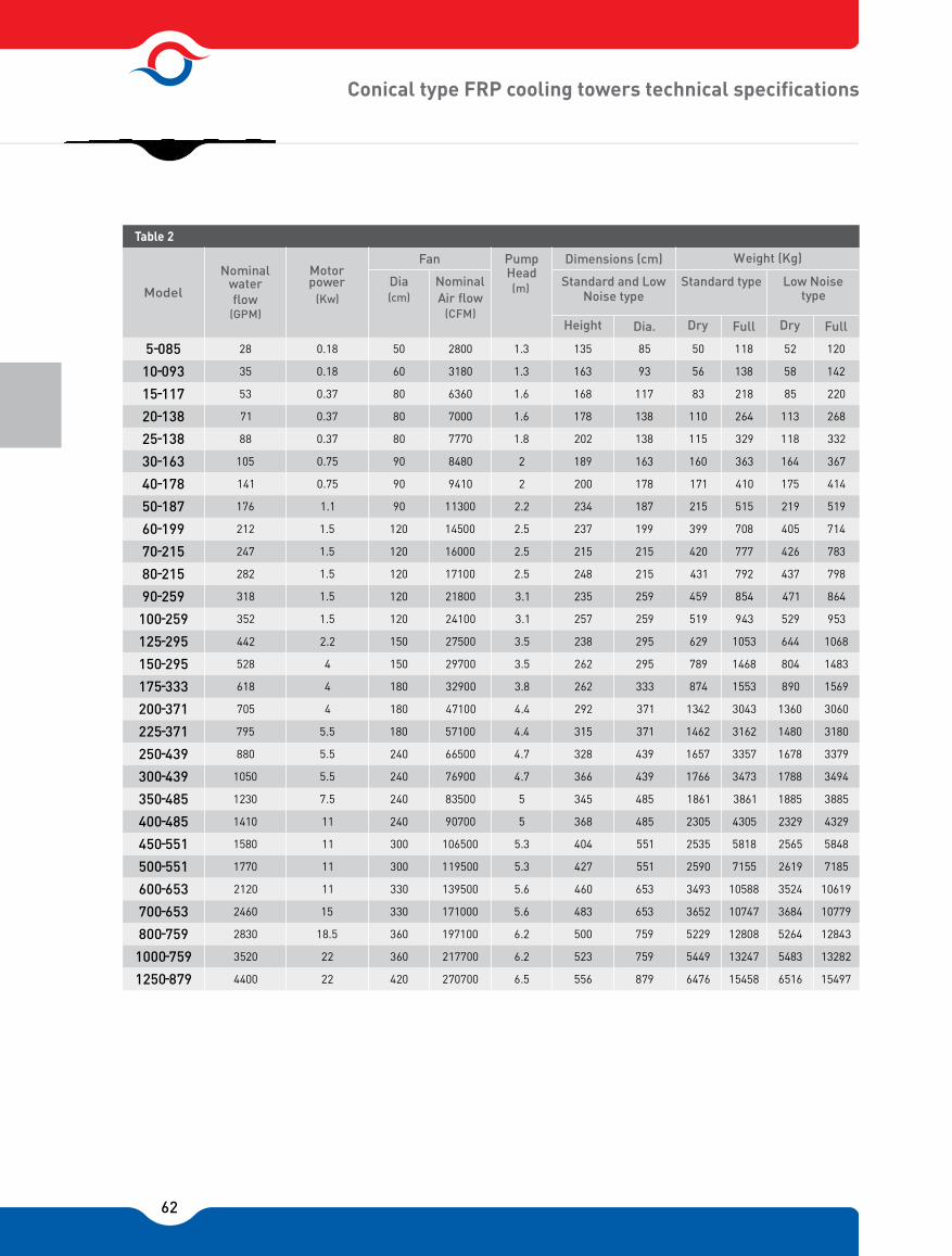
62
Conical type FRP cooling towers technical specifications
Pump Head (m)Dia
(cm)Nominal Air �ow
(CFM)
Standard and Low Noise type
Standard type Low Noise type
Height Dia. Dry Full Dry Full
28 0.18 50 2800 1.3 135 85 50 118 52 120
35 0.18 60 3180 1.3 163 93 56 138 58 142
53 0.37 80 6360 1.6 168 117 83 218 85 220
71 0.37 80 7000 1.6 178 138 110 264 113 268
88 0.37 80 7770 1.8 202 138 115 329 118 332
105 0.75 90 8480 2 189 163 160 363 164 367
141 0.75 90 9410 2 200 178 171 410 175 414
176 1.1 90 11300 2.2 234 187 215 515 219 519
212 1.5 120 14500 2.5 237 199 399 708 405 714
247 1.5 120 16000 2.5 215 215 420 777 426 783
282 1.5 120 17100 2.5 248 215 431 792 437 798
318 1.5 120 21800 3.1 235 259 459 854 471 864
352 1.5 120 24100 3.1 257 259 519 943 529 953
442 2.2 150 27500 3.5 238 295 629 1053 644 1068
528 4 150 29700 3.5 262 295 789 1468 804 1483
618 4 180 32900 3.8 262 333 874 1553 890 1569
705 4 180 47100 4.4 292 371 1342 3043 1360 3060
795 5.5 180 57100 4.4 315 371 1462 3162 1480 3180
880 5.5 240 66500 4.7 328 439 1657 3357 1678 3379
1050 5.5 240 76900 4.7 366 439 1766 3473 1788 3494
1230 7.5 240 83500 5 345 485 1861 3861 1885 3885
1410 11 240 90700 5 368 485 2305 4305 2329 4329
1580 11 300 106500 5.3 404 551 2535 5818 2565 5848
1770 11 300 119500 5.3 427 551 2590 7155 2619 7185
2120 11 330 139500 5.6 460 653 3493 10588 3524 10619
2460 15 330 171000 5.6 483 653 3652 10747 3684 10779
2830 18.5 360 197100 6.2 500 759 5229 12808 5264 12843
3520 22 360 217700 6.2 523 759 5449 13247 5483 13282
5-085
10-093
15-117
20-138
25-138
30-163
40-178
50-187
60-199
70-215
80-215
90-259
100-259
125-295
150-295
175-333
200-371
225-371
250-439
300-439
350-485
400-485
450-551
500-551
600-653
700-653
800-759
1000-759
1250-879 4400 22 420 270700 6.5 556 879 6476 15458 6516 15497
Table 2
Model water �ow
(GPM)
Nominal power
(Kw)
Motor Fan Dimensions (cm) Weight (Kg)

63
Conical type FRP cooling towers technical specifications
5-085
10-093
15-117
20-138
25-138
30-163
40-178
50-187
60-199
70-215
80-215
90-259
100-259
125-295
150-295
175-333
200-371
225-371
250-439
300-439
350-485
400-485
450-551
500-551
600-653
700-653
800-759
1000-759
1250-879
1.5
1.5
2
2
2
3
3
3
4
4
4
4
4
4
4
6
6
6
6
8
8
8
10
10
10
10
12
12
12
1.5
1.5
2
2
2
3
3
3
4
4
4
4
4
4
4
6
6
6
6
8
8
8
10
10
10
10
12
12
12
1
1
1
1
1
1
1
1
1.5
1.5
1.5
1.5
1.5
1.5
1.5
1.5
3
3
3
3
3
3
4
4
4
4
4
4
4
1
1
1
1
1
1
1
1
1.5
1.5
1.5
1.5
1.5
1.5
1.5
1.5
1.5
1.5
1.5
1.5
1.5
1.5
3
3
3
3
3
3
3
2/1
2/1
2/1
2/1
2/1
2/1
2/1
2/1
4/3
4/3
4/3
4/3
4/3
4/3
4/3
4/3
1
1
1
1
1
1
2
2
2
2
3
3
3
-
-
-
-
-
-
-
-
-
-
-
-
-
4/3
4/3
4/3
1
1
1
1
1
1
2
2
2
2
3
3
3
Model
Table 3
Inlet Outlet Over Flow Drain Quick Float Valve

64
Galvanized Cooling Tower Dimensions
L W H A B No. Size (Inch)
10 560 945 2150 533 460 1 1 ½ 1 1 ½ 285
15 740 945 2150 620 540 1 1 ½ 1 1 ½ 345
20 945 945 2200 750 655 1 2 1 2 410
25 945 1300 2200 750 655 1 2 1 2 500
30 945 1450 2250 1060 847 1 3 1 3 620
35 945 1450 2250 1060 847 1 3 1 3 695
40 1000 1940 2250 1060 847 1 3 1 3 755
50 1210 1940 2250 1060 847 1 3 1 3 880
60 1460 1940 2900 1060 847 1 4 1 4 1080
80 1940 1800 2900 1060 847 1 4 2 3 1500
90 1940 1940 2900 1060 847 1 4 2 3 1590
110 1940 2560 2900 1060 847 1 5 3 3 1790
120 1940 2890 3000 1060 847 1 5 3 3 2250
140 1940 3400 3000 1060 847 1 5 4 3 2500
160 1940 3860 3000 1060 847 2 4 4 3 3150
Model
Table 4
Outlet Water Inlet Water Weight (Kg) Size (Inch)No.
Dimensions (mm)

65
Galvanized Cooling Tower Dimensions
L W H A B No. Size (Inch)
Model
Table 4
Outlet Water Inlet Water Weight (Kg) Size (Inch)No.
Dimensions (mm)
180 1940 4400 3000 1060 847 2 4 5 3 3300
220 1940 5170 3000 1060 847 3 4 5 3 3850
260 1940 5670 3000 1060 847 3 4 6 3 4500
300 1940 6600 3000 1060 847 3 5 7 3 5200
340 1940 8000 3000 1060 847 3 5 8 3 5900
400 3780 5260 3100 1060 847 3 5 10 3 6900
450 3780 5730 3100 1060 847 3 5 12 3 8500
500 3780 6200 3100 1060 847 3 5 12 3 8800
590 3780 7120 3100 1060 847 3 5 14 3 9500
660 3780 8060 3100 1060 847 3 5 16 3 1140
750 3780 9000 3100 1060 847 3 5 18 3 12700
820 3780 9950 3200 1060 847 3 5 20 3 14400
900 3780 10840 3200 1060 847 3 5 22 3 15500
980 3780 11840 3200 1060 847 3 5 24 3 16700
1060 3780 12790 3200 1060 847 3 5 26 3 18150
1150 3780 13740 3200 1060 847 3 5 28 3 19400

66
GPM Air Flow CFM
Fan Motor power Pump Head (meter)
No. Size (Inch) Size (Hp)
Model
Table 5
No.
10 30 2850 1 12 1 3/4 23
15 45 4200 1 16 1 1 ½ 23
20 60 5700 1 18 1 2 23
25 75 7000 1 18 1 3 24
30 90 8500 1 22 1 3 24
35 105 9950 1 22 1 4 24
40 120 11400 1 22 1 5.5 24
50 150 14000 1 22 1 7.5 24
60 180 17000 1 22 1 7.5 24
80 225 24000 2 22 2 5.5 24
90 270 25000 2 22 2 5.5 24
110 330 29000 2 22 2 5.5 24
120 360 33000 3 22 3 5.5 24
140 420 40000 3 22 3 5.5 25
160 480 46000 4 22 4 5.5 25
180 540 49500 4 22 4 5.5 25
220 660 57000 5 22 5 5.5 25
260 780 68000 6 22 6 5.5 25
300 900 79500 7 22 7 5.5 25
340 1020 90000 8 22 8 5.5 25
400 1200 106000 10 22 10 5.5 25
450 1350 126000 12 22 12 5.5 25
500 1500 140000 12 22 12 5.5 25
590 1770 165000 14 22 14 5.5 25
660 1980 184000 16 22 16 5.5 25
750 2250 210000 18 22 18 5.5 25
820 2460 229000 20 22 20 5.5 25
900 2700 252000 22 22 22 5.5 25
980 2940 274000 24 22 24 5.5 25
1060 3180 296000 26 22 26 5.5 25
1150 3450 322000 28 22 28 5.5 25

67
Principals of FRP Cubic Cooling Tower operation "Tahvieh Azar Nasim" Fiberglass Cooling towers are inspired from the well-known "Sulzer" cooling tower design, and are designed and manufactured considering local Iranian facilities and requirements. The most important change in this design is considering service hatches which unfortunately are not considered in original design.
CasingDifferent parts of fiberglass body would be connected to each other by galvanized bolts and nuts and make the strong integrated body of the tower. The tower body can bear the wind pressure up to 21 m/s. and it thwart the vibrations caused by electro motor and fan.
BasinThe integrated rigid and reinforced basin is designed so that the amount of water reserves in basin should be as when the pump starts , air does not trap and when the pump is turn off water does not overflow the basin.
Fan Deck and Fan StackThe integrated rigid fan deck and fan stack, reinforced by fiberglass is designed to assist the air flow path.
FillsFiberglass cubic cooling towers suit two types of fills, film type and splash type. Cooling tower fills are designed to have the maximum contact of air with the water and cause the minimum pressure downfall.
FanThe light weight fan has good corrosion-resistant quality is an axial flow, multi blade version with adjustable blade pitch. The fan is designed to deliver large volumes of air at low power consumption and low noise generation.
The fans are dynamically balanced for smooth operation, longer bearing life including that of the supporting structure. FRP fan blades may also be provided on demand and these have in addition to excellent corrosion-resistance, good noise reduction properties.
ElectromotorSingle speed electromotor, Standard TEFC with IP55, �F� class are used in "Tahvieh Azar Nasim" cooling towers.Water Distribution systemLarge orifice polymeric nozzles (Non-clogging) are one of the significant benefits of cubic towers comparing the sprinklers of FRP conical type cooling towers.
Drift EliminatorPVC drift eliminator with three changes in air path gives us less than 0.002% drift loss.Considering the conditions of the area (height from the sea level) there is the option of changing the capacity of electromotor.
FRP Cubic Cooling Tower

68
Motor power Inlet (inch) Outlet (inch) Weight (Kg)
Length Width Height Dry Full
49.1 20 700 700 1300 0.37 1 1 45 105
49.2 30 700 700 1450 0.37 1 1 56 128
49.3 40 700 700 1600 0.55 1 1 65 140
72.1 50 850 850 1740 0.55 2 2 115 240
72.2 60 850 850 1740 0.55 2 2 121 250
72.3 80 850 850 2040 0.75 2 2 127 260
169.1 90 1300 1300 2320 0.75 3 3 270 587
169.2 135 1300 1300 2320 1.1 3 3 290 660
169.3 150 1300 1300 2320 1.5 3 3 310 695
272.1 186 1650 1650 2360 1.5 4 4 390 1220
272.2 218 1650 1650 2360 2.2 4 4 410 1330
272.3 235 1650 1650 2660 2.2 4 4 430 1450
361.1 265 1900 1900 2590 2.2 4 4 645 1510
361.2 290 1900 1900 2590 3 4 4 680 1620
361.3 320 1900 1900 2890 3 4 4 720 1740
528.1 400 2400 2200 2650 3 6 895 2950
528.2 460 2400 2200 2650 4 2 x 3 6 950 3075
528.3 500 2400 2200 2950 5.5 2 x 3 6 1000 3270
748.2 570 3400 2200 3620 5.5 2 x 4 6 1300 4100
748.3 720 3400 2200 3920 7.5 2 x 4 6 1380 4490
967.2 815 4300 2200 3690 7.5 2 x 4 6 1450 5150
967.3 890 4300 2200 3690 11 2 x 4 6 1550 5550
1333.1 1150 4300 3100 4100 11 3 x 3 2 x 4 2230 8300
1333.2 1300 4300 3100 4100 11 3 x 3 2 x 4 2385 8500
1333.3 1430 4300 3100 4100 15 3 x 3 2 x 4 2510 8700
1849.1 1600 4300 4300 4000 15 3 x 4 2 x 6 3050 11050
1849.2 1770 4300 4300 4000 18.5 3 x 4 2 x 6 3240 11250
1849.3 1840 4300 4300 4000 22 3 x 4 2 x 6 3410 11850
Model
Table 6
Dimensions (mm)GPMKw
2 x 3
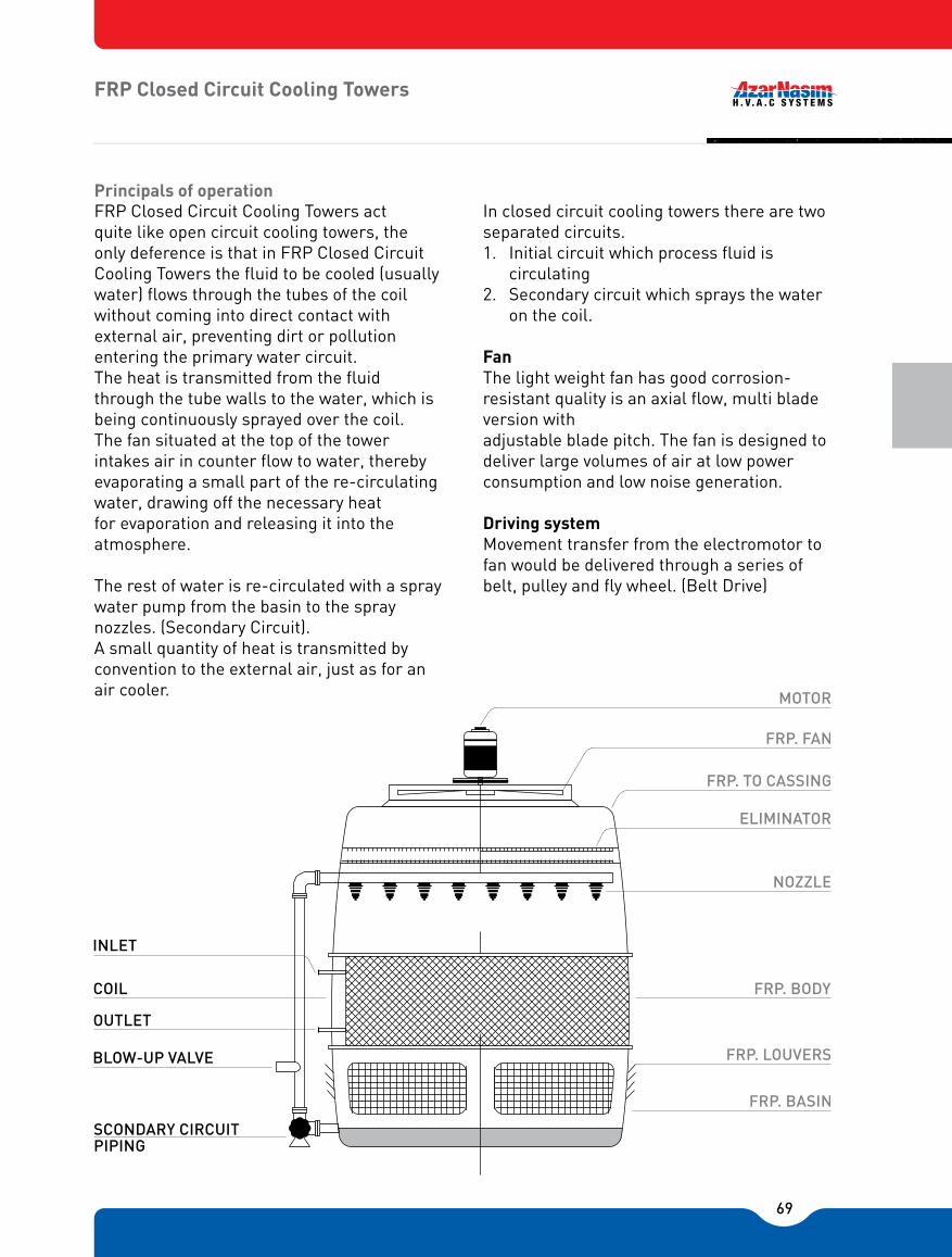
69
FRP Closed Circuit Cooling Towers
FRP Closed Circuit Cooling Towers act quite like open circuit cooling towers, the only deference is that in FRP Closed Circuit Cooling Towers the fluid to be cooled (usually water) flows through the tubes of the coil without coming into direct contact with external air, preventing dirt or pollution entering the primary water circuit. The heat is transmitted from the fluid through the tube walls to the water, which is being continuously sprayed over the coil.The fan situated at the top of the tower intakes air in counter flow to water, thereby evaporating a small part of the re-circulating water, drawing off the necessary heat for evaporation and releasing it into the atmosphere.
The rest of water is re-circulated with a spray water pump from the basin to the spray nozzles. (Secondary Circuit).A small quantity of heat is transmitted by convention to the external air, just as for an air cooler.
In closed circuit cooling towers there are two separated circuits.1. Initial circuit which process fluid is
circulating2. Secondary circuit which sprays the water
on the coil.
FanThe light weight fan has good corrosion-resistant quality is an axial flow, multi blade version withadjustable blade pitch. The fan is designed to deliver large volumes of air at low powerconsumption and low noise generation.
Driving systemMovement transfer from the electromotor to fan would be delivered through a series of belt, pulley and fly wheel. (Belt Drive)
Principals of operation
MOTOR
FRP. FAN
FRP. TO CASSING
ELIMINATOR
NOZZLE
FRP. BODY
FRP. LOUVERS
FRP. BASIN
INLET
COIL
OUTLET
BLOW-UP VALVE
SCONDARY CIRCUIT PIPING
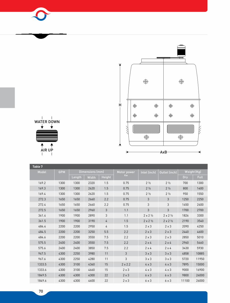
70
169.2 1300 1300 2320 1.5 0.75 2 ½ 2 ½ 700 1300
169.3 1300 1300 2620 1.5 0.75 2 ½ 2 ½ 800 1400
169.4 1300 1300 2620 1.5 0.75 2 ½ 2 ½ 950 1550
272.3 1650 1650 2660 2.2 0.75 3 3 1250 2250
272.4 1650 1650 2660 2.2 0.75 3 3 1450 2400
272.5 1650 1650 2960 3 1.1 3 3 1700 2700
361.4 1900 1900 2890 3 1.1 2 x 2 ½ 2 x 2 ½ 1826 3300
361.5 1900 1900 3190 4 1.5 2 x 2 ½ 2 x 2 ½ 2190 3540
484.4 2200 2200 2950 4 1.5 2 x 3 2 x 3 2090 4250
484.5 2200 2200 3250 5.5 2.2 2 x 3 2 x 3 2440 4600
484.6 2200 2200 3550 7.5 2.2 2 x 3 2 x 3 2850 5010
575.5 2400 2400 3550 7.5 2.2 2 x 4 2 x 4 2960 5460
575.6 2400 2400 3850 7.5 2.2 2 x 4 2 x 4 3430 5930
967.5 4300 2250 3980 11 3 3 x 3 3 x 3 4858 10885
967.6 4300 2250 4280 11 3 3 x 3 3 x 3 5720 11950
1333.5 4300 3100 4360 15 2 x 2.2 4 x 3 4 x 3 7895 15000
1333.6 4300 3100 4660 15 2 x 3 4 x 3 4 x 3 9000 16900
1849.5 4300 4300 4300 22 2 x 3 6 x 3 6 x 3 9800 24000
1849.6 4300 4300 4600 22 2 x 3 6 x 3 6 x 3 11100 26000
Motor power Inlet (inch) Outlet (inch) Weight (Kg)
Length Width Height Dry Full
Model
Table 7
Dimensions (mm)GPMKw
WATER DOWN
AIR UP
71
Electromotor Single speed electromotor, Standard TEFC with IP55, �F� class are used in "Tahvieh Azar Nasim" cooling Towers.
Drift EliminatorPVC drift eliminator with three changes in air path gives less than 0.002% drift loss.
Circulating water pumpCirculating water pump is a piece of closed circuit cooling tower which is designed to spray water on the Heat exchange coil and its electromotor would be cooled by fan (TEFC). Exit valve for Bleed off is Considered in pump circuit.
Industrial Cooling TowersPrincipals of "Tahvieh Azar Nasim" Industrial Cooling Towers is using finest raw materials and the highest Quality parts from well-known industries are used in "Tahvieh Azar Nasim" cooling towers in order to Ensure the high quality of tower in worst working conditions. All pieces can easily be carried, and makes fast installation at site results an integrated rigid cooling tower. "Tahvieh Azar Nasim" Cooling Towers are designed such as to use the modern polymeric substances as Much as possible. Fan deck, fan stack and casing are manufactured from fiberglass reinforced polymer, packing and drift Eliminators from PVC sheets or other polymer substances. The water distribution system would be through The PVC high pressure pipes and large orifice nozzles (non-clogging) made of polymers.The main structure would be made of fabric steel profiles which after manufacturing processes hot dipped Galvanized and then covered by a fiberglass layer. Fast and rigid Installation All the pieces would be easily installed by a couple of bolts and there is no need To any extra operation.
Rigid structureThe Structure of "Tahvieh Azar Nasim" cooling towers are made of galvanized steel fabric profiles which has provided the resistant structure and long lasting towers at peak industrial conditions.
FillsThe fills section is designed to bring about intimate contact of water and air so as to facilitate heat and mass Transfer at the same time aiding in proper and even distribution of air and water over the cross section, whilemaintaining minimum pressure downfall. The fills are of honeycomb section and are vacuum formed From anti- Bacterial Virgin PVC for excellent resistance to corrosion and give maximum area for Wattage.
FansMulti wings powerful axial Fan with high efficiency and low power consumption is one of the Best options for industrial cooling towers. FRP fan blades may also be provided on demand and these have In addition to excellent corrosion-resistance, good noise reduction properties.

72
Moving System Movement transfer from The electromotor to fan would occurred by means of shaft (greaducer drive) or by pulley ,flywheel and a series of belts. (Belt drives)
ElectromotorSingle speed electromotor, Standard TEFC with IP55, �F� class are used in "Tahvieh Azar Nasim" cooling Towers.
Casing, Fan Stack, Fan Deck"Tahvieh Azar Nasim" Cooling Towers packing are enclosed by fiberglass casings. Fan Stack and Fan Deck Are also made of fiberglass and designed as if the air suction occurs based on air path model.
Water distribution systemThe water distribution system is designed in such a way that provides the easy service and low pressure. Large orifice polymeric nozzles (Non-clogging) are one of the significant, benefits of industrial towers.Drift Eliminator"Tahvieh Azar Nasim" Industrial cooling towers drift eliminators are made of PVC with three changes in air Path and high efficiency. The drift Loss would be less than 0.002% by using these drifts eliminators.
LouversFRP louvers are installed at the air inlet (space between the Tower casing and water Basin) to prevent water Splash and prevents leaves, bird etc., entering the Cooling Tower. They could be easily detached to Access the tower's basin.
Technical Specifications"Tahvieh Azar Nasim" Industrial Cooling Towers are made and designed based on assumptions of client's requirements (suitable to be installed on a concrete basin).The concrete basin plan would be delivered to the client after the agreement, so that the civil contractor of client can construct the concrete basin as the "Tahvieh Azar Nasim" is manufacturing the pieces of Tower.

73
CED IR CDIII UI

74
INTRODUCTION
Packaged Unite
BENEFITS AND FEATURESAzarNasim packaged air conditioning units are compact systems intended for applications in new or existing stores, restaurants, offices, schools, computer rooms, airports, and industrial plants.Available in cooling capacities from 5 to 80 tons in a single unit, these units provide significant installation versatility and economy in that they can be used to supply the total cooling requirements in a variety of commercial, institutional, and industrial applications.
Units can be selected with air or water-cooled condensers in rooftop, indoor, and in case f aircooled versions in split or packaged arrangements.Furthermore, the units can be used for free delivery or ducted applications. For ease of installation, the units can be in vertical or horizontal configuration.
AzarNasim packaged units can provide year round air conditioning with hot water, steam or electric heating coil during the cold season. They can also be used to supplement central systems, permitting zone control at low load conditions without the expense of central systems.
Each unit is factory assembled, wired and shipped as a package. This greatly reduces installation time and assures the optimum positioning of the components.
In the areas where water supply is either unavailable or scarce, the air cooled units can be used. The aircooled split unit requires only the addition of the remotely located AzarNasim Air Cooled Condenser for complete air conditioning.
All components in AzarNasim packaged units aredesigned for maximum performance and reliability.
The basic component of the AzarNasim packaged unit is a semi-hermetic type multi-cylinder com-pressor designed to run on 380 volt, 3 phase, 50 cycle power input. Motor protection on these units is comprised of three sensors mounted internally in the motor windings which in case of charges in motor temperature shuts off the compressor. An oil safety switch provides protection against loss of oil pressure.All controls and factory wiring are protected within galvanized steel enclosures.The DX cooling coil is designed and rated accord-ing to ARI-410 Standard. To maximize perfor- mance, a venturi flow distributor assures even distribution of flow into the cooling coil tubes. Suction line piping is insulated with closed cell insulation to prevent moisture condensation. The DX coil section is insulated with 19mm rock wool panel with aluminum foil cover.
The water cooled condenser is a shell and tube type heat exchanger, sized sufficiently to hold the total refrigerant charge on pump down operations. An integrated sub-cooling section allows system capacity increase without an increase in power.The condenser shell design meets the ASME- Section VIII, DiV.1, Boiler & Pressure Vessel Coderequirements in addition to TEMA Standards.
The air-cooled condenser is configured so that air discharge is directed upward thus carrying heat away from the unit and minimizing directional sound. The fan is statically and dynamically balanced therefore assuring smooth and quiet operation.
For industrial process cooling and year round air conditioning, custom built units can also be designed and constructed.

75
PHYSICAL DATA
1. All units are shipped with a holding charge. However, operating charge dose not include charge for remote air-cooled condenser or refrigerant connection piping. Operating charge values are approximate.
2. Fan size in TABLES 1& 2 is selected for nominal conditions. Addition of special filters and other accessories will vary the fan size requirement.
Note:
W A
COMPRESSOR CAPACITY (Tons)
NO OF COMPRESSORS
6.0 2.5 5.5 2.2 6.5 2.8 11.7 4.8 11.7 4.9 11.8 6.7 17.0 7.0 27.6 11.0 27.6 11.5
Number of rows Fins per inch Tube O.D (in)
Total face area (sq.ft)
Number Size (in)
Nominal CFM
Horsepower @ 1450 RPM 0.75 2.0 2.0 4.0 5.5 5.5 7.5 7.5 10.0
Total face area (sq.ft) Thickness (in)
No x shell diam. (in) Integrall� nned tube O.D. (in)
OPERATING WEIGHT (Kg) 441 341 523 420 615 492 700 559 780 631 846 686 931 745 1100 872 1200 969
5-1 8-1 10-1 15-1 20-1 25-1 30-1 35-1 40-1
48
5/84
48
5/86.4
48
5/88.0
48
5/812
48
5/816
48
5/820
48
5/823.4
48
5/828.0
48
5/832.0
113
2000
114
3200
114
4000
116
6000
117
8000
119
10000
217
12000
217
14000
217
16000
5.22
7.62
8.32
12.52
17.72
23.62
26.62
29.22
38.22
1 x 63/4
1 x 63/4
1 x 63/4
1 x 63/4
1 x 83/4
1 x 83/4
1 x 10³/4
1 x 10³/4
1 x 10³/4
Table 1 PHYSICAL DATA
UNIT SP W W W W W W W W A A A A A A A A
1 1 1 1 1 1 1 1 1
5 8 10 15 20 25 30 35 40
REFRIGERANT R-22 Operating charge (kg)
EVAPORATOR FAN
STANDARD MOTOR
RETURN-AIR FILTER
CONDENSER (watercooled)
EVAPORATOR COIL
W A
COMPRESSOR CAPACITY (Tons)
NO OF COMPRESSORS
Number of rows Fins per inch Tube O.D (in)
Total face area (sq.ft)
Number Size (in)
Nominal CFM
Horsepower @ 1450 RPM
Total face area (sq.ft) Thickness (in)
No x shell diam. (in) Integrall� nned tube O.D. (in)
OPERATING WEIGHT (Kg)
48
5/8
48
5/8
48
5/8
48
5/8
48
5/8
48
5/8
48
5/8
48
5/8
48
5/8
1 1 1 1 1 1 2 2 2
2 2 2 2 2 2 2 2 2
2 x 63/4
2 x 63/4
2 x 63/4
2 x 63/4
2 x 83/4
2 x 83/4
2 x 10³/4
2 x 10³/4
2 x 10³/4
Table 2 PHYSICAL DATA
UNIT SP W W W W W W W W A A A A A A A A
2
5 8 10 15 20 25 30 35 40
REFRIGERANT R-22 Operating charge (kg)
EVAPORATOR FAN
STANDARD MOTOR
RETURN-AIR FILTER
CONDENSER (watercooled)
EVAPORATOR COIL
2 2 2 2 2 2 2 2
20.0
80-2
62.0
2232000
67.9
11.5 4.5 11.0 4.0 12.7 5.5 24.4 10.5 24.4 10.8 27.6 11.2 33.9 14.0 56.2 23.1 55.1 23.1
2.0 4.0 5.5 7.5 10.0 15.0 15.0 15.0
670 473 920 706 1100 831 1230 952 1400 1087 1550 1233 1780 1407 2100 1664 2300 1815
10-2 15-2 20.2 30-2 40-2 50-2 60-2 70-2
8.0 12.0 16.0 24.0 32.0 40.0 48.0 57.6
144000
166000
1712000
1716000
1720000
1924000
2228000
178000
10.4 13.0 25.0 36.5 43.9 55.9 63.917.7

76
SELECTION PROCEDURE
Given:SUMMER CONDITISION:Total Cooling Load (TC)................................720 MBHSensible Heat Capacity (SHC)......................530 MBHAir Flow Rate............................................24000 CFMEntering Dry Bulb Temp. (EDB).........................80 °FEntering Wet Bulb Temp. (EWB)........................67 °FAir Entering Condenser Temp. (AEC).................90°FCondensing Temp. (CT)....................................125 °F
WINTER CONDITIONTotal Heating Load....................................800 MBHEntering Air Temp. EDB..................................50 °FEntering Hot Water Temp. EHT.....................160 °FTemperature Drop...........................................10 °FAir Flow Rate.........................................24000 CFMExternal Static Pressure............................0.5" w.g.Altitude.....................................................Sea Level
Find:A. Unit size and capacity.B. Total heat rejection.C. Leaving dry/wet bulb temperatures.D. Heating capacity.E. Fan speed and HP.
A. Consider Model Anpu-70-A-2 from TABLE 38,Interpolating between 23040 and 25920 CFM at 67 °F EWB, results in the following quantities:
Total Cooling Capacity (TC) = 725.9 MBHSensible Heat Capacity (SHC) = 539.3 MBHCompressor Power Consumption = 62.6 KW
B. To determine the Total Heat Rejection, THR, enter TABLE 38 with CT = 125 °F and interpolate between 23040 and 25920 CFM. The THR is then found to be:
THR = 939.6 MBH
Next, to select an air cooled condenser, refer to the Total Heat Rejection Chart in the AzarNasim Air Cooled Condenser Catalog with:
TD = 125 - 90 = 35 °FModel Anpu-550-R can be selected to appropriately reject the total heat.
C. The Leaving Dry Bulb temperature can be calculated using the following relation:
SHC LDB = EDB - 1.087 xCFM
539300 LDB = 80 °F - = 59.3 °F 1.087 x24000The Leaving Wet Bulb temperature can be calculated according to the following method:
TC x 1000 H2 = H1 - 4.5 x CFM
735.9 x 1000 = 31.62 - = 24.9 BTU/Ib 4.5 x 24000From TABEL 64, at 0 altitude interpolate between 24.48 and 25.12 BTU/lb to read LWB = 57.7 °F
D. From the Heating Coil Ratings in TABLE 45, for Model Anpu-70-A-2,a 1 row heating coil (Full Circuit-8 FPI) with the following specifications can be selected:
Heating Capacity = 1,001,800 BTU/hrAir Flow Rate = 28000 CFM
Since the CFM listed in the table is not equal to the design CFM, a correction factor must be applied.
CFM 24000 = = 85.7 %NOMINAL CFM 28000
From TABLE 42, interpolating between 80% and 90%, a correction factor of 0.92 is obtained. Next, a hot water coil correction factor must be determined.Enter Figure 1 at 50 °F EDB and moving vertically upward to 160 °F EHT, the correction factor can be found to be 0.93 The actual heating capacity is then:
Actual Heating Capacity = 1,001, 800 x 0.92 x 0.93 = 857,200 BTU/hr
E. From TABLE 43, for a 1 row coil, the internal static pressure is found by interpolation to be 0.07" w.g. Similarily for a 4-row cooling coil, the static pressure drop is found to be 0.4" w.g. The
EXAMPLE 1: Air Cooled Model

77
SELECTION PROCEDURE
total system pressure drop is:∆ P Total = ∆ P internal + ∆ P external
= (0.07" + 0.4") + 0.5" = 0.97" w.g.
From the Fan Performance Chart on TABLE 49, for Model AnpuA-70-2 with a static pressure of 0.97" w.g., 24000 CFM, and interpolating between 0.75" and 1" static pressure the following quantities can be selected for the fan:
RPM = 512 HP = 10
EXAMPLE 2: Water Cooled Model
Given:SUMMER CONDITIONTotal Cooling Load (TC)......................206 MBHSensible Heat Capacity (SHC)............103 MBHAir Flow Rate....................................5500 CFMEntering Dry Bulb Temp. (EDB)...............80 °FEntering Wet Bulb Temp. (EWB)..............72 °FCondenser Entering Water Temp. (EWT).85 °F
WINTER CONDITIONTotal Heating Load.......................................270 MBHEntering Dry Bulb Temp. (EDB).........................60 °FEntering Hot Water Temp. (EWT).....................160 °FTemperature Drop..............................................20 °FAir Flow Rate..................................................5500 °FExternal Static Pressure...............................0.5" w.g.Altitude........................................................Sea Level
Find:A. Unit size and capacity.B. Condenser water flow rate.C. Condenser pressure drop.D. Leaving dry/wet bulb temperatures.E. Heating capacity.F. Fan speed and HP.
A. Consider Model AnpuW-15-1 from TABLE 7 , interpolating between 5400 and 6000 CFM at 72 °F EWB, Permits the determination of the following quantities:
Total Capacity (TC) = 207.6 MBHSensible Heat Capacity (SHC) = 105.7 MBHCompressor Power Consumption = 10.2 KWB. From TABLE 7, the condenser water flow rate is:GPM = 45.1
C. From TABLE 7, the condenser pressure drop isPD = 16.2 ft. water
D. The Leaving Dry Bulb temperature is calculated according to the following relation:
SHC LDB = EDB - 1.087 xCFM
105700 LDB = 80 °F - = 62.3 °F 1.087 x5500The Leaving Wet Bulb temperature can be calculated according to the following method:
TC x 1000 H2 = H1 - 4.5 x CFM
207.6 x 1000 = 35.83 - = 27.4 BTU/Ib 4.5 x 5500From TABLE 64, interpolating between 27.85 and 28.57 BTU/lb result in LWB = 61.4 °F.
E. The Heating Coil Capacity for Model AnpuW-15-1 configured with a 2-row coil (Full Circuit-8 FPI) and EDB = 60 °F , from TABLE 45, is:Heating Capacity = 338.7 MBH
Next, the hot water coil correction factor of 0.85 can be read from Figure 1 at the intersection of a vertically projected line from 60 °F entering air temperature up to the 160 °F entering water temperature line and projection horizontally to the left to correction factor axis.Since the CFM in the table is not equal to the design CFM, a correction factor must be applied.
CFM 5500 = = 91.7 %NOMINAL CFM 6000
Interpolating between 90% and 100% in TABLE 42,a correction factor 0.96 is obtained. Applying the hot water and CFM correction factors to obtain theactual heating capacity as:Actual Heating Capacity = 338700 x 0.85 x 0.96= 276.4 MBHF. The total static pressure, fan speed, and horse power are calculated similar to the procedure outlined in part e) of EXAMPLE 1 as:∆ P Total = 1.1" w.g.RPM = 780 HP = 3

78
SELECTION PROCEDURE
Notes:Air cooled condensers must operate under different ambient conditions is order to provide sufficient heat rejection from the air conditioning cycle. All manu- facturers therefore publish condenser ratings under a standard condition. For any condition other than the standard condition stated by the manufacturer, correction factors must be applied to the total heat rejection in the packaged rating tables. One such correction factor is altitude correction factor given in the table below which must be applied to the total heat rejected from the air cooled packaged unit in order to select the appropriate air cooled condenser.
EXAMPLE 3: Altitude Correction Factor
Suppose the air cooled condenser of EXAMPLE 1 is to operate under the same summer and winter condition except at the location stated below:
Geographic Location: TehranAltitude: 1190 metersThe unit selection and the calculation of the TotalHeat Rejection (THR) is identical to the steps a) andB) in EXAMPLE 1. Hence:
Model Anpu-70-A-2THR = 939.6 MBH
From TABLE 3, the Correction Factor CF = 1.0902 by interpolation. Applying CF to the Total Heat Rejection leads to the new value for THR:
THRNew = THR x 1.0902 = 939.6 X 1.0902 = 1024 MBH
From AzarNasim Air Cooled Condenser Catalog forTD = 35 °F and THR New = 1024 MBH, air cooledcondenser Model Anpu-700-R can be selected.
EXAMPLE 4: Non Standard ConditionWater Cooled Model
Given:SUMMER CONDITIONTotal Cooling Load (TC).................................260 MBHSensible Heat Capacity (SHC).......................140 MBHAir Flow Rate...............................................8800 MBHEntering Dry Bulb Temp. (EDB)..........................83 °FEntering Wet Bulb Temp. (EWB).........................67 °FCondenser Entering Water Temp. (EWT)............85 °FDesign Leaving Dry Bulb Temp. (DLDB).............66 °FCoil Face Area (FA)..........................................16.0 FT²Altitude..................................................................0 FT
Select Anpu-20-W-1 from TABLE 8, with TC=240.8 MBH and SHC=186 MBH at 80 °F EDB. The face velocity, FV, is calculated according to the following relation:
CFM 8800 FV = = = 550 FPM FA 16.0
Where the face area, FA, for packaged units is listed in TABLE 1. With the calculated face velocity enter TABLE 40, under the 4-row coil the Bypass Factor, BF, is given as 0.26. Next, enter TABLE 41, at 83 °F EDB and interpolate between 0.25 and 0.30 BF. The CF is then calculated as 2.42. The corrected TC and SHC for EDB=83 °F can be determined according to:
TC = 240800 + 8800 x 2.42 = 262000 BTUHSHC = 186000 + 8800 x 2.42 = 207000 BTUH
Since the calculated TC and SHC can atisfactorily meet the given load, the leaving dry bulb temperature can be calculated as:
207000 LDB = 83 °F - = 61.4 °F 1.087 x8800
It can thus be seen that the design leaving dry bulbtemperature of 66 °F can be attained.
The leaving Wet Bulb temperature can be calculated according to the following method:
TC 262000 H2 = H1 - = 35.83 - = 24.9 BTU/Ib 4.5 x CFM 4.5 x 8800
From TABLE 64 at 0 altitude interpolate between 29.31 and 28.57 BTU/lb to read LWB =63.8 °F.
-ALTIYUDE CORRECTION FACTOR
ALTITUTE (m)
Table 3
CF ALTITUDE (m) CF
0
310
625
940
1250
1.000
1.023
1.047
1.070
1.095
1400
1550
1720
1880
2000
1.107
1.119
1.132
1.145
1.158

79
WATER COOLED PACKAGED UNIT RATINGS
Note: All ratings are based on 80°F EDB according to ARI standards 310-90 and 360-86.
95.4
92.3
5.4
10.5
92.0
91.4
5.6
11.0
88.7
88.7
6.2
11.9
105.8
76.5
5.4
10.5
102.8
75.3
5.7
11.1
98.1
73.4
6.4
12.1
115.7
60.2
5.
10.4
113.6
59.5
5.8
11.3
107.3
57.5
6.5
12.3
94.5
87.5
5.4
10.5
113.6
59.5
5.8
11.3
107.3
57.5
6.5
12.3
103.8
73.6
5.4
10.5
100.6
72.4
5.7
11.1
96.2
71.0
6.3
12.1
113.9
58.5
5.4
10.4
111.1
57.6
5.8
11.3
106.3
55.9
6.5
12.3
92.5
83.6
5.4
10.5
89.2
82.1
5.6
10.9
85.6
80.5
6.2
11.8
102.1
70.3
5.4
10.5
98.8
68.8
5.7
11.1
94.8
67.3
6.3
12.0
112.4
56.6
5.4
10.4
109.0
55.3
5.8
11.2
105.0
54.0
6.4
12.3
90.6
78.9
5.4
10.5
87.4
77.3
5.6
10.9
83.9
75.9
6.1
11.8
99.9
66.8
5.4
10.5
96.7
65.6
5.7
11.1
92.9
63.9
6.3
12.0
110.5
54.4
5.4
10.4
106.8
53.2
5.8
11.2
102.4
51.8
6.4
12.2
24.4
24.0
23.5
13.4
13.0
12.4
131.8
121.2
6.7
13.0
124.9
118.0
7.5
14.2
118.9
115.3
8.3
15.5
146.2
101.7
6.7
13.0
138.9
98.6
7.6
14.3
132.1
96.0
8.5
15.7
161.5
81.9
6.6
12.9
153.5
78.9
7.6
14.4
146.0
76.1
8.6
15.8
129.8
115.6
6.7
13.0
123.0
112.9
7.5
14.2
117.0
110.1
8.3
15.4
143.7
97.7
6.7
13.0
136.6
94.6
7.6
14.3
130
92.0
8.5
15.7
158.7
79.4
6.6
12.9
150.9
76.4
7.6
14.4
143.7
73.7
8.6
15.8
124.3
104.0
6.6
12.9
118.2
101.1
7.5
14.1
112.5
98.4
8.2
15.3
140.9
93.4
6.7
13.0
133.9
90.5
7.6
14.3
127.5
88.0
8.5
15.6
155.7
76.5
6.7
12.9
148.3
73.7
7.6
14.4
141.3
71.0
8.6
15.8
124.3
104.0
6.6
12.9
118.2
101.1
7.5
14.1
112.5
98.4
8.2
15.3
137.4
89.0
6.7
13.0
130.8
86.1
7.6
14.3
124.7
83.6
8.4
15.6
152.0
73.6
6.7
13.0
144.9
70.7
7.6
14.4
138.1
68.1
8.5
15.8
3200 3600 4000 4400
33.3
32.5
31.8
16.5
15.7
15.1
CFM CONDENSER
FACE VELOCITY(FPM)
EWT (°F)
GPM PD(ft) EWB( °F)
TC (MBH)
SHC (MBH)
Input Power (KW)
Current (AMP.)
TC (MBH)
SHC (MBH)
Input Power (KW)
Current (AMP.)
TC (MBH)
SHC (MBH)
Input Power (KW)
Current (AMP.)
62
63.5
59.6
2.6
5.8
60.8
58.5
3.0
6.3
58.1
57.6
3.4
6.7
67
70.5
49.9
2.6
5.7
67.6
48.7
3.0
6.2
64.6
47.6
3.4
6.8
72
78.0
40.0
2.5
5.6
74.8
38.8
3.0
6.2
71.5
37.6
3.4
6.8
62
62.5
57.0
2.6
5.8
59.8
55.7
3.0
6.3
57.1
54.6
3.4
6.7
67
69.4
48.0
2.6
5.7
66.5
46.8
3.0
6.2
63.6
45.5
3.4
6.8
72
76.8
38.6
2.5
5.6
73.7
37.6
3.0
6.2
70.4
36.4
3.4
6.8
62
61.4
53.9
2.7
5.8
58.8
52.9
3.0
6.3
56.1
51.7
3.4
6.7
67
68.1
45.8
2.6
5.7
65.3
44.5
3.0
2.6
62.5
43.5
3.4
6.8
72
75.3
37.3
2.5
5.6
72.3
36.1
3.0
6.2
69.2
35.0
3.4
6.8
62
59.9
51.2
2.7
5.8
57.3
50.1
3.0
6.3
54.8
48.8
3.40
6.7
67
66.4
43.5
2.6
5.8
63.8
42.4
3.0
6.3
61.1
41.1
3.4
6.8
72
73.5
35.8
2.5
5.7
70.7
34.7
3.0
6.2
67.7
33.6
3.4
6.8
1600
400
1800
450
2000
500
2200
550
75
85
95
15.7
15.3
15.0
8.2
7.8
7.5
TABLE 4
CFM CONDENSER
FACE VELOCITY(FPM)
EWT (°F)
GPM PD(ft) EWB( °F)
TC (MBH)
SHC (MBH)
Input Power (KW)
Current (AMP.)
TC (MBH)
SHC (MBH)
Input Power (KW)
Current (AMP.)
TC (MBH)
SHC (MBH)
Input Power (KW)
Current (AMP.)
626772626772626772626772
2560
400
2880
450
3200
500
3520
550
75
85
95
TABLE 5
CFM CONDENSER
FACE VELOCITY(FPM)
EWT (°F)
GPM PD(ft) EWB( °F)
TC (MBH)
SHC (MBH)
Input Power (KW)
Current (AMP.)
TC (MBH)
SHC (MBH)
Input Power (KW)
Current (AMP.)
TC (MBH)
SHC (MBH)
Input Power (KW)
Current (AMP.)
626772626772626772626772
400 450 500 550
75
85
95
TABLE 6
Anpu-5-W-1 RATINGS
Anpu-8-W-1 RATINGS
Anpu-10-W-1 RATINGS

80
Note: ratings are based on 80°F EDB according to ARI standards 310-90 and 360-86.
WATER COOLED PACKAGED UNIT RATINGS
33.3
32.5
31.8
16.5
15.7
15.1
CFM CONDENSER
FACE VELOCITY(FPM)
EWT (°F)
GPM PD(ft) EWB( °F)
TC (MBH)
SHC (MBH)
Input Power (KW)
Current (AMP.)
TC (MBH)
SHC (MBH)
Input Power (KW)
Current (AMP.)
TC (MBH)
SHC (MBH)
Input Power (KW)
Current (AMP.)
626772626772626772626772
400 450 500 550
75
85
95
TABLE 7
CFM CONDENSER
FACE VELOCITY(FPM)
EWT (°F)
GPM PD(ft) EWB( °F)
TC (MBH)
SHC (MBH)
Input Power (KW)
Current (AMP.)
TC (MBH)
SHC (MBH)
Input Power (KW)
Current (AMP.)
TC (MBH)
SHC (MBH)
Input Power (KW)
Current (AMP.)
626772626772626772626772
400 450 500 550
75
85
95
TABLE 8
CFM CONDENSER
FACE VELOCITY(FPM)
EWT (°F)
GPM PD(ft) EWB( °F)
TC (MBH)
SHC (MBH)
Input Power (KW)
Current (AMP.)
TC (MBH)
SHC (MBH)
Input Power (KW)
Current (AMP.)
TC (MBH)
SHC (MBH)
Input Power (KW)
Current (AMP.)
626772626772626772626772
400 450 500 550
75
85
95
TABLE 9
181.3
176.0
8.9
17.6
174.7
172.7
10.1
19.3
167.8
167.7
11.2
21.2
201.8
146.1
8.9
17.6
193.6
142.4
10.2
19.5
185.2
139.4
11.5
21.5
222.7
115.9
8.9
17.5
213.7
113.1
10.3
19.6
204.5
109.5
11.6
21.8
179.4
167.0
8.9
17.6
171.4
164.7
10.0
19.3
164.4
160.7
11.2
21.1
198.8
139.8
8.9
17.6
190.9
136.5
10.2
19.5
182.7
133.2
11.4
21.5
219.3
112.0
8.9
17.5
210.6
108.9
10.3
19.6
201.6
105.7
11.6
21.8
176.2
158.8
8.9
17.5
169.1
155.6
10.0
19.3
153.8
152.6
11.1
21.0
195.5
133.6
8.9
17.6
187.2
130.6
10.2
19.5
179.2
127.4
11.4
21.0
215.4
107.8
8.9
17.6
207.0
105.0
10.2
19.6
198.4
101.7
11.6
21.7
172.3
149.8
8.9
17.5
165.5
146.5
10.0
19.2
158.5
143.5
11.1
20.9
190.6
127.1
8.9
17.6
183.2
124.1
10.1
19.4
175.7
120.6
11.3
21.3
210.7
103.9
8.9
17.6
202.7
100.6
10.2
19.6
194.3
97.5
11.5
21.7
4800 5400 6000 6600
45.8
45.1
44.3
16.7
16.2
15.7
227.4
227.4
10.0
19.7
219.7
219.7
11.3
21.4
211.7
211.7
12.7
23.3
249.7
189.9
9.9
19.6
240.8
186.0
11.3
21.4
230.0
181.7
12.8
23.5
273.7
149.1
9.8
19.4
264.6
146.0
11.3
21.4
252.5
142.4
12.9
23.5
223.5
219.5
10.0
19.8
215.1
215.1
11.3
21.4
252.5
142.4
12.9
23.5
246.3
181.9
9.9
19.6
237.6
178.1
11.3
21.4
227.1
173.9
12.8
23.3
270.3
143.8
9.8
19.4
261.5
140.4
11.3
21.4
249.9
136.7
12.9
23.5
220.2
207.9
10.0
19.8
211.3
204.6
11.3
21.4
201.9
200.1
12.6
23.2
242.5
173.5
10.0
19.7
233.9
169.4
11.3
21.4
223.7
165.3
12.8
23.4
265.9
138.8
9.8
19.4
257.3
135.5
11.3
21.4
246.1
131.4
12.9
23.5
216.0
196.1
10.1
19.8
207.6
191.9
11.3
21.4
198.3
188.2
12.6
23.2
237.7
164.7
10.0
19.7
229.2
161.2
11.3
21.4
219.4
157.0
12.8
23.4
260.9
133.1
9.8
19.5
252.4
130.0
11.3
21.4
241.6
125.7
12.9
23.5
6400 7200 8000 8800
57.1
56.4
55.3
17.0
16.6
15.9
285.7
285.2
13.1
24.6
227.1
227.1
14.7
26.8
267.2
267.2
16.5
29.4
315.5
234.5
13.0
24.5
305.4
229.8
14.8
26.9
291.9
225.0
16.7
29.6
346.3
184.5
12.9
24.3
335.9
161.7
14.8
26.9
320.4
176.6
16.8
29.8
280.4
272.0
13.1
24.6
270.9
267.3
14.7
26.8
260.6
260.1
16.4
29.3
311.3
224.7
13.0
24.5
301.2
220.9
14.8
26.9
287.9
215.9
16.7
29.6
341.8
178.0
12.9
24.3
331.8
174.4
14.8
26.9
317.4
169.2
16.8
29.8
277.1
257.2
13.1
24.6
266.8
252.8
14.7
26.8
225.5
247.6
16.4
29.2
305.8
214.8
13.0
24.5
295.9
210.4
14.7
26.9
283.1
205.9
16.6
29.5
336.4
171.7
12.9
24.3
326.5
168.4
14.8
26.9
312.3
162.8
16.8
29.8
216.0
196.1
10.1
19.8
207.6
191.9
11.3
21.4
198.3
188.2
12.6
23.2
237.7
164.7
10.0
19.7
229.2
161.2
11.3
21.4
219.4
157.0
12.8
23.4
260.9
133.1
9.8
19.5
252.4
130.0
11.3
21.4
241.6
125.7
12.9
23.5
8000 9000 10000 11000
71.1
70.3
69.0
23.8
23.4
22.5
Anpu-15-W-1 RATINGS
Anpu-20-W-1 RATINGS
Anpu-25-W-1 RATINGS

81
Note: All ratings are based on 80°F EDB according to ARI standards 310-90 and 360-86.
WATER COOLED PACKAGED UNIT RATINGS
CFM CONDENSER
FACE VELOCITY(FPM)
EWT (°F)
GPM PD(ft) EWB( °F)
TC (MBH)
SHC (MBH)
Input Power (KW)
Current (AMP.)
TC (MBH)
SHC (MBH)
Input Power (KW)
Current (AMP.)
TC (MBH)
SHC (MBH)
Input Power (KW)
Current (AMP.)
626772626772626772626772
400 450 500 550
75
85
95
TABLE 10
CFM CONDENSER
FACE VELOCITY(FPM)
EWT (°F)
GPM PD(ft) EWB( °F)
TC (MBH)
SHC (MBH)
Input Power (KW)
Current (AMP.)
TC (MBH)
SHC (MBH)
Input Power (KW)
Current (AMP.)
TC (MBH)
SHC (MBH)
Input Power (KW)
Current (AMP.)
626772626772626772626772
400 450 500 550
75
85
95
TABLE 11
CFM CONDENSER
FACE VELOCITY(FPM)
EWT (°F)
GPM PD(ft) EWB( °F)
TC (MBH)
SHC (MBH)
Input Power (KW)
Current (AMP.)
TC (MBH)
SHC (MBH)
Input Power (KW)
Current (AMP.)
TC (MBH)
SHC (MBH)
Input Power (KW)
Current (AMP.)
626772626772626772626772
400 450 500 550
75
85
95
TABLE 12
486.4
476.2
24.1
43.1
467.7
765.6
27.0
46.8
448.1
448.1
30.2
50.9
540.8
389.2
24.1
43.1
521.5
381.4
27.2
47.1
496.9
371.8
30.7
51.6
595.6
311.0
23.9
42.8
576.3
303.0
27.3
47.2
549.7
293.0
30.9
52.0
482.6
446.6
24.1
43.1
462.9
441.0
27.0
46.8
441.4
427.8
30.1
50.8
533.4
372.6
24.1
43.1
514.3
364.8
27.2
47.1
489.8
355.9
30.6
51.5
586.2
301.9
24.0
42.9
567.0
294.0
27.3
47.2
540.8
285.0
30.9
52.0
475.1
423.9
24.1
43.1
456.0
414.9
26.9
46.7
433.7
409.0
30.0
50.7
523.2
357.0
24.1
43.1
504.3
349.3
27.2
47.0
481.0
340.1
30.5
51.4
575.9
291.1
24.0
42.9
557.1
281.4
27.3
47.2
531.8
271.9
30.9
51.9
465.0
400.2
24.1
43.1
446.7
391.4
26.8
46.6
425.8
382.3
29.9
50.5
512.0
339.7
24.1
43.1
493.6
331.3
24.2
47.0
471.3
322.1
30.4
51.3
563.8
279.4
24.1
43.0
545.3
270.6
27.3
47.2
520.9
260.8
30.9
51.8
12800 14400 16000 17600
123.1
121.1
118.8
22.7
22.1
21.1
407.9
403.0
20.3
38.6
394.4
394.4
22.8
42.2
379.6
379.6
25.5
46.2
452.1
331.9
20.3
38.5
436.7
326.3
23.0
42.4
416.3
317.3
25.9
46.8
403.9
383.0
20.3
38.6
389.1
376.0
22.7
42.1
372.2
372.2
25.4
46.1
446.2
317.6
20.3
38.5
430.9
311.7
22.9
42.4
410.6
304.2
25.8
46.7
489.8
253.0
20.2
38.3
474.1
247.3
23.0
42.5
451.8
240.2
26.0
47.0
398.3
362.8
20.3
38.5
382.5
356.8
22.7
42.1
365.1
348.7
25.3
46.0
439.4
304.2
20.3
38.5
424.6
297.2
22.9
42.4
404.6
290.1
25.3
46.0
481.5
243.8
20.2
38.3
466.5
238.4
23.0
42.5
445.4
230.6
26.0
47.0
11200 12600 14000 15400
103.1
101.8
99.7
19.9
19.5
18.7
337.7
335.8
16.0
27.9
326.8
326.8
18.0
30.7
314.7
314.7
20.1
33.8
373.9
276.3
16.0
27.9
361.3
271.1
18.1
31.0
344.9
262.0
20.4
34.3
411.0
217.3
16.0
27.7
398.7
213.2
18.2
31.0
380.6
206.8
20.6
34.5
332.1
320.0
16.0
27.9
319.9
314.0
17.9
30.6
307.1
307.1
20.0
33.7
368.6
264.5
16.1
27.9
356.3
259.6
18.1
30.9
340.3
253.4
20.4
34.2
405.5
210.1
16.0
27.8
393.0
205.1
18.2
31.0
375.8
199.5
20.6
34.5
328.6
301.4
16.0
27.8
315.5
297.1
17.9
30.6
301.5
290.7
19.9
33.6
362.3
253.2
16.1
27.9
350.2
247.6
18.1
30.9
334.7
241.0
20.3
34.1
215.4
107.8
8.9
17.6
207.0
105.0
10.2
19.6
198.4
101.7
11.6
21.7
172.3
149.8
8.9
17.5
165.5
146.5
10.0
19.2
158.5
143.5
11.1
20.9
190.6
127.1
8.9
17.6
183.2
124.1
10.1
19.4
175.7
120.6
11.3
21.3
390.9
193.9
16.0
27.8
379.1
190.2
18.2
31.0
362.8
183.8
20.5
34.5
9360 10530 11700 12870
84.7
83.6
82.0
21.5
20.8
20.2
Anpu-30-W-1 RATINGS
Anpu-35-W-1 RATINGS
Anpu-40-W-1 RATINGS
471.9 429.3 390.6 497.2
234.3 289.2 342.7 260.8
20.2 20.3 20.3 20.2
38.4 38.6 38.5 38.3
457.1 414.7 375.9 481.7
228.8 283.6 336.0 254.0
23.0 22.9 22.7 23.0
42.5 42.3 42.0 42.5
436.7 396.1 358.3 459.7
221.8 275.3 328.3 246.2
26.0 25.7 25.2 26.0
47.0 46.5 45.8 47.0

82
Note: ratings are based on 80°F EDB according to ARI standards 310-90 and 360-86.
WATER COOLED PACKAGED UNIT RATINGS
8800
6400
4400CFM CONDENSER
FACE VELOCITY(FPM)
EWT (°F)
GPM PD(ft) EWB( °F)
TC (MBH)
SHC (MBH)
Input Power (KW)
Current (AMP.)
TC (MBH)
SHC (MBH)
Input Power (KW)
Current (AMP.)
TC (MBH)
SHC (MBH)
Input Power (KW)
Current (AMP.)
626772626772626772626772
400 450 500 550
75
85
95
TABLE 13
CFM CONDENSER
FACE VELOCITY(FPM)
EWT (°F)
GPM PD(ft) EWB( °F)
TC (MBH)
SHC (MBH)
Input Power (KW)
Current (AMP.)
TC (MBH)
SHC (MBH)
Input Power (KW)
Current (AMP.)
TC (MBH)
SHC (MBH)
Input Power (KW)
Current (AMP.)
626772626772626772626772
400 450 500 550
75
85
95
TABLE 14
CFM CONDENSER
FACE VELOCITY(FPM)
EWT (°F)
GPM PD(ft) EWB( °F)
TC (MBH)
SHC (MBH)
Input Power (KW)
Current (AMP.)
TC (MBH)
SHC (MBH)
Input Power (KW)
Current (AMP.)
TC (MBH)
SHC (MBH)
Input Power (KW)
Current (AMP.)
626772626772626772626772
400 450 500 550
75
85
95
TABLE 15
263.6
242.4
13.3
25.9
249.9
36.1
15.1
28.5
237.7
230.6
16.7
30.9
292.4
203.4
13.4
26.0
227.8
197.3
15.2
28.7
264.2
192.0
17.0
31.4
259.5
231.2
13.3
25.9
246.1
225.8
15.0
28.4
234.0
220.1
16.6
30.9
287.5
195.3
13.4
26.0
273.2
189.2
15.2
28.7
260.0
184.1
17.0
31.4
317.5
158.8
13.3
25.9
301.9
152.8
15.3
28.8
287.4
147.5
17.2
31.7
254.7
214.5
13.3
25.9
241.8
214.0
15.0
28.4
230.0
208.5
16.6
30.8
281.7
186.9
13.4
26.0
267.8
181.0
15.2
28.6
255.1
176.0
16.9
31.3
311.4
152.9
13.3
25.9
296.5
147.0
15.3
28.8
282.5
142.0
17.1
31.6
248.6
208.2
13.3
25.8
236.3
202.2
14.9
28.3
225.0
196.9
16.5
30.7
274.7
178.2
13.4
26.0
261.7
172.2
15.1
28.6
249.4
167.1
16.8
31.2
304.1
147.2
13.3
25.9
289.7
141.5
15.3
28.8
276.3
137.6
17.1
31.6
6400 7200 8000
66.6
65.0
63.6
16.5
15.7
15.1
186.0
173.6
10.9
21.0
179.7
170.5
11.2
21.9
172.7
172.7
12.4
23.7
205.4
144.5
10.9
21.0
179.7
170.5
11.2
21.9
172.7
172.7
12.4
23.7
225.8
114.6
10.7
20.8
219.2
112.5
11.6
22.5
210.8
109.8
12.9
24.6
183.2
169.2
10.8
21.0
176.8
166.1
11.2
21.8
169.7
163.0
12.3
23.6
202.2
141.6
10.9
21.0
195.7
138.9
11.4
22.2
187.8
136.0
12.6
24.1
223.2
113.4
10.8
20.9
215.9
110.8
11.6
22.5
208.1
108.0
12.9
24.5
180.1
160.6
10.9
21.0
173.6
157.7
11.1
21.8
166.6
154.6
12.3
23.5
198.6
135.5
10.9
21.0
192.1
132.7
11.3
22.1
184.5
129.6
12.6
24.0
219.9
109.5
10.8
20.9
212.3
106.8
11.5
22.4
204.0
103.6
12.8
24.4
176.2
151.7
10.9
21.0
170.0
148.9
11.1
21.7
163.2
145.8
12.2
23.4
193.9
129.1
10.9
21.0
188.2
125.9
11.3
22.0
180.9
122.9
12.5
23.9
215.1
105.5
10.8
20.9
207.7
102.7
11.5
22.3
199.7
99.5
12.8
24.3
4800 5400 6000
47.9
46.9
46.2
13.4
13.0
12.4
128.6
120.0
5.3
11.5
123.2
117.4
6.1
12.5
117.6
116.0
6.8
13.5
143.0
100.8
5.1
11.4
137.0
98.0
6.0
12.5
131.0
95.8
6.9
13.5
158.2
80.6
5.0
11.2
151.8
78.2
5.9
12.3
145.0
76.0
6.8
13.5
126.6
114.4
5.3
11.6
121.2
112.0
6.1
12.5
115.8
109.6
6.8
13.5
140.6
96.8
5.2
11.4
134.8
94.2
6.0
12.5
128.8
92.0
6.9
13.5
155.5
78.1
5.0
11.2
149.2
75.6
6.0
12.4
142.8
73.4
6.9
13.5
124.1
109.0
5.3
11.6
119.0
106.4
6.1
12.5
113.6
104.2
6.8
13.5
137.6
92.4
5.2
11.5
132.2
90.0
6.0
12.5
126.4
87.6
6.9
13.5
152.4
75.4
5.0
11.3
146.4
73.2
6.0
12.4
140.2
70.8
6.9
13.5
121.2
103.0
5.3
11.6
116.2
100.6
6.1
12.5
111.0
98.2
6.1
13.5
134.4
87.8
5.2
11.5
129.0
85.4
6.1
12.5
123.6
83.0
6.9
13.5
148.8
72.4
5.1
11.3
143.0
70.0
6.0
12.4
137.0
68.0
6.9
13.5
3200 3600 4000
31.7
31.1
30.5
8.2
7.8
7.5
Anpu-15-W-2 RATINGS
Anpu-10-W-2 RATINGS
Anpu-20-W-2 RATINGS
323.0
163.8
13.3
25.8
307.0
157.9
15.3
28.8
292.0
152.3
17.2
31.7

83
Note: All ratings are based on 80°F EDB according to ARI standards 310-90 and 360-86.
WATER COOLED PACKAGED UNIT RATINGS
CFM CONDENSER
FACE VELOCITY(FPM)
EWT (°F)
GPM PD(ft) EWB( °F)
TC (MBH)
SHC (MBH)
Input Power (KW)
Current (AMP.)
TC (MBH)
SHC (MBH)
Input Power (KW)
Current (AMP.)
TC (MBH)
SHC (MBH)
Input Power (KW)
Current (AMP.)
626772626772626772626772
400 450 500 550
75
85
95
TABLE 16
CFM CONDENSER
FACE VELOCITY(FPM)
EWT (°F)
GPM PD(ft) EWB( °F)
TC (MBH)
SHC (MBH)
Input Power (KW)
Current (AMP.)
TC (MBH)
SHC (MBH)
Input Power (KW)
Current (AMP.)
TC (MBH)
SHC (MBH)
Input Power (KW)
Current (AMP.)
626772626772626772626772
400 450 500 550
75
85
95
TABLE 17
CFM CONDENSER
FACE VELOCITY(FPM)
EWT (°F)
GPM PD(ft) EWB( °F)
TC (MBH)
SHC (MBH)
Input Power (KW)
Current (AMP.)
TC (MBH)
SHC (MBH)
Input Power (KW)
Current (AMP.)
TC (MBH)
SHC (MBH)
Input Power (KW)
Current (AMP.)
626772626772626772626772
400 450 500 550
75
85
95
TABLE 18
448.9
448.8
20.1
39.5
434.7
434.6
22.6
42.9
418.8
418.8
25.4
46.6
493.6
370.0
19.9
39.3
475.8
362.9
22.6
42.9
454.3
354.8
25.6
46.9
541.6
289.1
19.6
38.8
523.5
283.1
22.5
42.7
499.9
275.5
25.8
47.1
442.3
427.5
20.1
39.5
425.9
421.6
22.6
42.8
409.2
408.6
25.3
46.5
487.3
354.2
19.9
39.3
469.9
347.0
22.6
42.9
449.1
338.7
25.6
46.9
534.5
279.2
19.6
38.9
516.9
273.1
22.6
42.8
494.0
265.1
25.8
47.1
435.4
405.6
20.1
39.5
425.9
421.6
22.6
42.8
409.2
408.6
25.3
46.5
479.3
338.9
20.0
39.4
462.2
331.0
22.6
42.9
442.1
323.2
25.6
46.8
529.5
269.5
19.7
39.0
509.1
263.3
22.6
42.8
487.0
255.1
25.7
47.1
427.0
383.1
20.1
39.6
410.2
375.3
22.5
42.8
392.5
367.4
25.2
46.3
470.0
322.0
20.0
39.4
453.1
314.7
22.6
42.9
433.6
306.9
25.5
46.8
516.6
258.7
19.7
39.1
499.5
252.0
22.6
42.8
478.0
244.2
25.7
47.1
4800 5400 6000 6400
111.0
109.4
107.3
17.0
16.6
15.9
353.9
341.5
17.8
35.1
339.7
336.3
20.1
38.6
326.5
326.5
22.3
42.1
392.3
284.8
17.8
35.2
376.7
277.9
20.3
39.0
360.4
271.1
22.8
42.9
432.6
226.0
17.8
35.1
415.3
219.8
20.5
39.3
397.4
213.6
23.2
43.5
348.4
326.5
17.8
35.2
334.3
320.2
20.0
38.5
319.9
316.3
22.2
41.9
386.3
272.8
17.8
35.2
371.2
267.0
20.3
39.0
355.2
260.5
22.7
42.8
426.5
218.3
17.8
35.1
409.7
212.0
20.5
39.2
392.4
205.7
23.1
43.4
342.7
310.0
17.7
35.0
328.9
303.8
20.0
38.4
314.6
297.7
22.1
41.8
379.1
261.3
17.8
35.2
364.4
254.7
20.3
38.9
349.4
248.2
22.7
42.7
419.0
210.7
17.8
35.2
402.8
204.4
20.4
39.2
385.7
198.8
23.1
43.3
335.6
292.8
17.7
35.0
322.3
286.3
19.9
38.3
308.6
280.7
22.0
41.6
371.2
247.9
17.8
35.2
351.7
241.7
20.2
38.8
342.4
235.6
22.6
42.5
409.9
202.2
17.8
35.2
394.4
196.2
20.4
39.1
378.5
190.1
23.0
43.2
9600 10800 12000 13200
89.4
88.1
86.5
16.7
16.2
15.7
565.0
565.0
26.1
49.2
547.3
547.3
29.4
53.7
527.2
527.2
32.9
58.6
620.9
464.8
26.0
49.0
600.5
457.0
29.5
53.8
573.9
449.5
33.3
59.2
682.0
364.2
25.7
48.5
661.3
357.0
29.5
53.8
631.8
347.0
33.6
59.5
555.5
536.4
26.2
49.2
533.9
533.9
29.3
53.6
514.9
514.9
32.8
58.5
612.8
445.0
26.1
49.0
592.8
437.0
29.5
53.8
566.9
425.7
33.3
59.1
673.0
353.0
25.8
48.6
652.8
344.8
29.5
53.8
624.2
334.7
33.6
59.5
535.8
479.6
26.1
49.2
516.5
472.1
29.2
53.4
495.1
460.5
32.6
58.1
590.5
403.7
26.1
49.1
571.2
396.2
29.5
53.8
547.2
386.0
33.3
59.1
649.8
325.2
25.9
48.8
630.3
318.2
29.5
53.9
603.6
308.4
33.5
59.4
16000 18000 20000 22000
140.4
138.7
136.1
23.8
23.4
22.5
546.6
509.1
26.2
49.2
526.8
499.7
29.3
53.5
500.5
494.4
32.7
58.2
602.6
424.8
26.1
49.1
582.9
416.9
29.5
53.8
557.8
407.2
33.2
59.0
662.6
339.6
25.8
48.7
642.7
331.9
29.5
53.9
615.1
322.6
33.6
59.5
Anpu-30-W-2 RATINGS
Anpu-40-W-2 RATINGS
Anpu-50-W-2 RATINGS
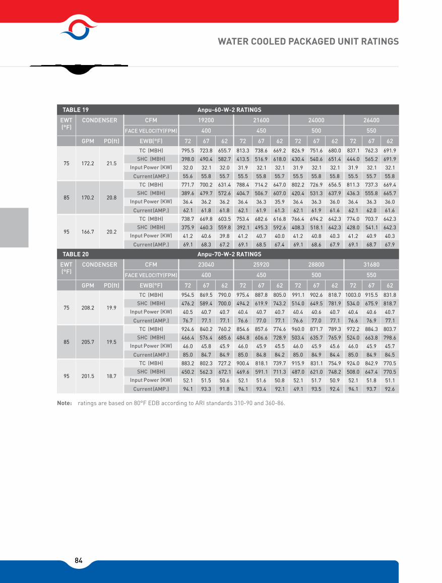
84
Note: ratings are based on 80°F EDB according to ARI standards 310-90 and 360-86.
WATER COOLED PACKAGED UNIT RATINGS
28800 31680
24000 26400CFM CONDENSER
FACE VELOCITY(FPM)
EWT (°F)
GPM PD(ft) EWB( °F)
TC (MBH)
SHC (MBH)
Input Power (KW)
Current (AMP.)
TC (MBH)
SHC (MBH)
Input Power (KW)
Current (AMP.)
TC (MBH)
SHC (MBH)
Input Power (KW)
Current (AMP.)
626772626772626772626772
400 450 500 550
75
85
95
TABLE 19
CFM CONDENSER
FACE VELOCITY(FPM)
EWT (°F)
GPM PD(ft) EWB( °F)
TC (MBH)
SHC (MBH)
Input Power (KW)
Current (AMP.)
TC (MBH)
SHC (MBH)
Input Power (KW)
Current (AMP.)
TC (MBH)
SHC (MBH)
Input Power (KW)
Current (AMP.)
626772626772626772626772
400 450 500 550
75
85
95
TABLE 20
831.8
818.7
40.7
77.1
803.7
798.6
45.7
84.5
770.5
770.5
51.1
92.6
915.5
675.9
40.6
76.9
884.3
663.8
45.9
84.9
842.9
647.4
51.8
93.7
1003.0
534.0
40.4
76.6
972.2
524.0
46.0
85.0
924.0
508.0
52.1
94.1
818.7
781.9
40.7
77.1
789.3
765.9
45.6
84.4
754.9
748.2
50.9
92.4
902.6
649.5
40.6
77.0
871.7
635.7
45.9
84.9
831.1
621.0
51.7
93.5
991.1
514.0
40.4
76.6
960.0
503.4
46.0
85.0
915.9
487.0
52.1
49.1
805.0
743.2
40.7
77.1
774.6
728.9
45.5
84.2
739.7
711.3
50.8
92.1
887.8
619.9
40.7
77.0
857.6
606.6
45.9
84.8
818.1
591.1
51.6
93.4
975.4
494.2
40.4
76.6
854.6
484.8
46.0
85.0
900.4
469.6
52.1
94.1
23040 25920
208.2
205.7
201.5
19.9
19.5
18.7
790.0
700.0
40.7
77.1
760.2
685.6
45.9
84.9
727.2
672.1
50.6
91.8
869.5
589.4
40.7
77.1
840.2
576.4
45.8
84.7
802.3
562.3
51.5
93.3
954.5
476.2
40.5
76.7
924.6
466.4
46.0
85.0
883.2
450.2
52.1
94.1
691.9
691.9
32.1
55.8
669.4
665.7
36.0
61.6
642.3
642.3
40.3
67.9
762.3
565.2
32.1
55.7
737.3
555.8
36.3
62.0
703.7
541.1
40.9
68.7
837.1
444.0
31.9
55.5
811.3
436.3
36.4
62.1
774.0
428.0
41.2
69.1
680.0
651.4
32.1
55.8
656.5
637.9
36.0
61.6
642.3
642.3
40.3
67.9
751.6
540.6
32.1
55.8
726.9
531.3
36.3
61.9
694.2
518.1
40.8
68.6
826.9
430.4
31.9
55.5
802.2
420.4
36.4
62.1
766.4
408.3
41.2
69.1
669.2
618.0
32.1
55.7
647.0
607.0
35.9
61.3
616.8
592.6
40.0
67.4
738.6
516.9
32.1
55.8
714.2
506.7
36.3
61.9
682.6
495.3
40.7
68.5
813.3
413.5
31.9
55.5
788.4
404.7
36.4
62.1
753.4
392.1
41.2
69.1
19200 21600
172.2
170.2
166.7
21.5
20.8
20.2
655.7
582.7
32.0
55.7
631.4
572.6
36.2
61.8
603.5
559.8
39.8
67.2
723.8
490.4
32.1
55.8
700.2
479.7
36.2
61.8
669.8
460.3
40.6
68.3
795.5
398.0
32.0
55.6
771.7
389.6
36.4
62.1
738.7
375.9
41.2
69.1
Anpu-60-W-2 RATINGS
Anpu-70-W-2 RATINGS

85
1. Direct interpolation is permissible but do not extrapolate.2. In calculating the cooling load and power input (KW), the heat generated by the
evaporator fan has not been taken into account.3. Ratings are based on 10 °F subcooling.4. All ratings are based on 80 °F EDB according to ARI standards 310-90 and 360-86.
Rating Table Notes:
Formulas, (At sea level):
THR (MBH) = Gross Total Capacity (MBH) + 3.413 x Compressor Power Input (KW) (For suction cooled compressors)
THR(BTU/hr GPM = (Water Flow Rate) 500x ∆T
SHC(BTU/hr) LDB = EDB - (For cooling and heating coils) 1.087 xCFM
TC (BTU/hr) H2 = H1 - (For cooling coil) 4.45 x CFM
WATER COOLED PACKAGED UNIT RATINGS
245.5
242.1
237.1
22.7
22.1
21.1
CFM CONDENSER
FACE VELOCITY(FPM)
EWT (°F)
GPM PD(ft) EWB( °F)
TC (MBH)
SHC (MBH)
Input Power (KW)
Current (AMP.)
TC (MBH)
SHC (MBH)
Input Power (KW)
Current (AMP.)
TC (MBH)
SHC (MBH)
Input Power (KW)
Current (AMP.)
626772626772626772626772
400 450 500 550
75
85
95
TABLE 21
1080.1
766.6
48.2
86.2
1041.5
751.1
54.5
94.2
992.1
731.9
61.3
103.2
1187.9
609.6
47.9
85.7
1148.7
596.8
54.6
94.4
1094.4
578.3
61.9
103.9
964.2
877.2
48.2
86.2
924.4
861.8
53.9
93.5
880.7
840.2
60.1
101.6
1062.7
737.1
48.3
86.2
1024.8
720.2
54.4
94.2
976.8
702.4
61.2
138.0
1169.2
589.2
48.0
85.8
1131.2
577.8
54.6
94.4
1079.4
558.2
61.9
103.9
947.1
833.8
48.2
86.2
909.5
815.7
53.8
93.4
865.0
799.4
59.9
101.3
1042.9
704.6
48.3
86.2
1006.1
687.9
54.4
94.1
960.2
669.6
61.0
102.8
1149.0
568.5
48.1
85.9
1111.8
555.7
54.6
94.4
1061.4
535.7
61.9
103.9
24800 27900 31000 341
925.4
788.0
48.1
86.1
889.2
772.8
53.6
93.2
848.0
752.1
59.7
101.0
1018.6
671.6
48.3
86.3
982.6
654.0
54.3
93.9
939.1
636.2
60.8
102.5
1121.9
548.0
48.1
86.0
1085.2
535.9
54.6
94.4
1037.0
516.4
61.7
103.6
Anpu-80-W-2 RATINGS
976.0
923.1
48.3
86.2
938.1
902.9
54.0
93.6
895.7
881.7
60.3
101.8

86
1. Direct interpolation is permissible but do not extrapolate.2. In calculating the cooling load and power input (kw), the
heat generated by the evaporator fan has not been taken into account.
Rating Table Notes: 3. Ratings are based on 10 °F subcooling.4. All ratings are based on 80°F EDB according to ARI
standards 310-90 and 360-865. Standard air cooled condenser rating are based on 125
°F condensing temperature according to ARI Standard 460-(87).
AIR COOLED PACKAGED UNIT RATINGS
35203200
22002000CFM
FACE VELOCITY(FPM)
CT (°F)
EWB( °F)
TC (MBH)
SHC (MBH)
Input Power (KW)
Current (AMP.)
626772626772626772626772
400 450 500 550
TABLE 22
THR (MBH)
TC
TC
TC
(MBH)
(MBH)
(MBH)
SHC
SHC
SHC
(MBH)
(MBH)
(MBH)
Input
Input
Input
Power
Power
Power
(KW)
(KW)
(KW)
Current
Current
Current
(AMP.)
(AMP.)
(AMP.)
THR (MBH)
THR (MBH)
THR (MBH)
CFM
FACE VELOCITY(FPM)
CT(°F)
EWB( °F)
TC (MBH)
SHC (MBH)
Input Power (KW)
Current (AMP.)
626772626772626772626772
400 450 500 550
THR (MBH)
TC
TC
TC
(MBH)
(MBH)
(MBH)
SHC
SHC
SHC
(MBH)
(MBH)
(MBH)
Input
Input
Input
Power
Power
Power
(KW)
(KW)
(KW)
Current
Current
Current
(AMP.)
(AMP.)
(AMP.)
THR (MBH)
THR (MBH)
THR (MBH)
TABLE 23
2560 2880
105
115
125
135
1600 1800
105
115
125
135
88.7
88.7
6.2
11.9
109.9
85.3
85.3
6.8
12.8
105.6
81.5
81.5
7.4
13.8
106.9
77.2
77.2
8.0
14.8
104.7
98.1
73.4
6.4
12.1
119.8
93.5
71.6
7.0
13.1
117.3
88.3
69.9
7.6
14.1
114.2
82.4
68.0
8.2
15.1
110.5
107.3
57.5
6.5
12.3
129.5
102.9
55.9
7.1
13.4
127.3
97.3
54.2
8.8
15.9
127.3
90.2
51.6
8.4
15.4
118.9
87.3
85.3
6.2
11.9
108.4
84.0
82.1
6.8
12.8
107.2
80.4
78.4
8.4
15.3
109.0
76.2
74.3
8.0
14.7
103.5
96.2
71.0
6.3
12.1
117.8
91.6
69.3
6.9
13.0
115.3
86.7
67.3
7.6
14.0
112.5
81.4
65.0
8.2
15.0
109.3
106.3
55.9
6.5
12.3
128.4
101.4
54.2
7.1
13.4
125.8
96.1
52.1
8.8
15.9
126.1
89.6
49.7
8.4
15.4
118.3
58.1
57.6
3.4
6.7
69.7
55.6
55.6
3.8
7.2
68.5
53.2
53.2
4.2
7.7
67.4
50.8
50.8
4.5
8.2
66.3
64.6
47.6
3.4
6.8
76.3
61.5
46.3
3.8
7.3
74.6
58.3
45.2
4.2
7.8
72.8
55
43.9
4.6
8.4
70.8
71.5
37.6
3.4
6.8
83.2
68.1
36.5
3.9
7.3
81.4
64.6
33.
4.3
7.9
79.3
61.0
34.0
4.7
8.5
77.2
57.1
54.6
3.4
6.7
68.8
54.3
53.4
3.8
7.2
67.2
51.9
51.9
4.1
7.7
66.0
49.6
49.5
4.5
8.2
64.9
63.6
45.5
3.4
6.8
75.3
60.6
44.3
3.8
7.3
73.7
57.5
43.2
4.2
7.8
71.9
54.3
41.9
4.6
8.3
70.0
70.4
36.4
3.4
6.8
82.2
67.1
35.2
3.9
7.3
80.3
63.7
34.0
4.3
7.9
78.5
60.3
32.8
4.7
8.5
76.4
56.1
51.7
3.4
6.7
67.7
53.5
50.5
3.8
7.2
66.3
50.6
49.2
4.1
7.7
64.6
48.2
48.0
4.5
8.1
63.4
62.5
43.5
3.4
6.8
74.2
59.5
42.4
3.8
7.3
72.6
56.5
41.1
4.2
7.8
70.9
53.4
39.8
4.6
8.3
69.1
69.2
35.0
3.4
6.8
80.9
66.0
33.9
3.9
7.3
79.2
62.7
32.7
4.3
7.9
77.4
59.3
31.5
4.7
8.5
75.4
54.8
48.8
3.4
6.7
58.2
52.3
47.5
3.7
7.2
65.1
49.7
46.3
4.1
7.6
63.7
46.9
45.2
4.4
8.1
62.0
61.1
41.1
3.4
6.8
72.8
58.3
40.0
3.8
7.3
71.3
55.4
38.8
4.2
7.8
69.7
52.4
37.7
4.6
8.3
68.0
67.7
33.6
3.4
6.8
79.4
64.6
32.5
3.9
7.37
77.8
61.5
31.3
4.3
7.97
76.1
58.3
30.0
4.7
8.4
74.3
Anpu-5-A-1 RATINGS
Anpu-8-A-1 RATINGS
102.4
51.8
6.4
12.2
124.3
98.0
50.1
7.1
13.3
122.1
92.9
48.1
7.7
14.3
119.3
87.1
46.1
8.4
15.4
115.7
92.9
63.9
6.3
12.0
114.4
88.8
62.1
6.9
14.2
112.3
84.2
60.3
7.5
13.9
109.7
78.9
58.2
8.1
14.9
106.5
83.9
75.9
6.1
11.8
104.9
80.1
74.1
6.7
12.6
102.9
75.9
72.4
7.2
13.5
100.6
71.3
70.8
7.8
14.4
98
105.3
54.0
6.4
12.3
127.0
99.9
52.2
7.1
13.3
124.1
94.7
50.3
7.8
14.4
121.1
88.4
48.1
8.4
15.4
117.1
94.8
67.3
6.3
12.0
116.4
90.5
65.6
6.9
13.0
114.2
85.7
63.6
7.5
14.0
111.5
80.3
61.5
8.1
15.0
108.1
85.6
80.5
6.2
11.8
106.7
81.7
78.6
6.7
12.7
104.7
77.6
77.0
7.3
13.6
102.5
73.4
73.4
7.9
14.6
100.4
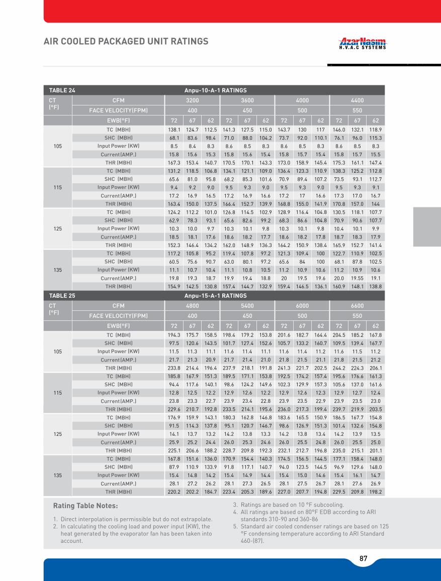
87
1. Direct interpolation is permissible but do not extrapolate.2. In calculating the cooling load and power input (KW), the
heat generated by the evaporator fan has been taken into account.
Rating Table Notes: 3. Ratings are based on 10 °F subcooling.4. All ratings are based on 80°F EDB according to ARI
standards 310-90 and 360-865. Standard air cooled condenser ratings are based on 125
°F condensing temperature according to ARI Standard 460-(87).
AIR COOLED PACKAGED UNIT RATINGS
66006000
44004000CFM
FACE VELOCITY(FPM)
CT(°F)
EWB( °F)
TC (MBH)
SHC (MBH)
Input Power (KW)
Current (AMP.)
626772626772626772626772
400 450 500 550
TABLE 24
THR (MBH)
TC
TC
TC
(MBH)
(MBH)
(MBH)
SHC
SHC
SHC
(MBH)
(MBH)
(MBH)
Input
Input
Input
Power
Power
Power
(KW)
(KW)
(KW)
Current
Current
Current
(AMP.)
(AMP.)
(AMP.)
THR (MBH)
THR (MBH)
THR (MBH)
CFM
FACE VELOCITY(FPM)
CT(°F)
EWB( °F)
TC (MBH)
SHC (MBH)
Input Power (KW)
Current (AMP.)
626772626772626772626772
400 450 500 550
THR (MBH)
TC
TC
TC
(MBH)
(MBH)
(MBH)
SHC
SHC
SHC
(MBH)
(MBH)
(MBH)
Input
Input
Input
Power
Power
Power
(KW)
(KW)
(KW)
Current
Current
Current
(AMP.)
(AMP.)
(AMP.)
THR (MBH)
THR (MBH)
THR (MBH)
TABLE 25
105
115
125
135
105
115
125
135
4800 5400
167.8
167.7
11.2
21.2
206.1
161.3
161.6
12.4
23.0
203.5
154.8
154.8
13.5
25.0
201.1
148.0
148.0
14.7
26.9
198.2
185.2
139.4
11.5
21.5
224.3
176.6
137.0
12.7
23.5
219.9
167.7
132.6
13.9
25.5
215.1
158.4
129.6
16.1
27.6
209.8
204.5
109.5
11.6
21.8
244.2
195.6
105.6
12.9
23.9
239.7
186.5
101.4
14.2
26.0
235.0
177.1
96.9
15.4
28.1
229.5
164.4
160.7
11.2
21.1
202.5
157.4
157.3
12.3
22.9
199.4
150.9
151.3
13.4
24.8
196.8
144.5
144.5
14.6
26.7
194.8
182.7
133.2
11.4
21.5
221.7
174.2
129.9
12.6
23.5
217.3
165.5
126.9
13.8
25.5
212.7
156.5
123.5
15.0
27.5
207.7
201.6
105.7
11.6
21.8
241.3
192.5
102.3
12.9
23.9
236.0
183.6
98.6
14.2
26.0
232.1
174.5
94.0
15.4
28.1
227.0
153.8
152.6
11.1
21.0
191.8
153.8
149.6
12.2
22.8
195.6
146.8
146.7
13.3
24.6
192.3
140.3
140.7
14.4
26.5
189.6
179.2
127.4
11.4
21.4
218.1
171.1
124.2
12.6
23.4
214.1
162.8
120.7
13.8
25.3
209.8
154.4
117.1
14.9
27.3
205.3
198.4
101.7
11.6
21.7
237.9
189.5
98.6
12.9
23.9
233.5
180.3
95.1
14.2
26.0
228.7
170.9
91.8
15.4
28.1
223.4
158.5
143.5
11.1
20.9
196.4
151.3
140.1
12.2
22.7
192.8
143.1
137.8
13.2
24.4
188.2
136.0
133.9
14.2
26.2
184.7
175.7
120.6
11.3
21.3
214.4
167.9
117.6
12.5
23.3
210.7
159.9
114.3
13.7
25.2
206.6
151.6
110.9
14.8
27.2
202.2
194.3
97.5
11.5
21.7
233.8
185.8
94.4
12.8
23.8
229.6
176.9
91.5
14.1
25.9
225.1
167.8
87.9
15.4
28.1
220.2
3200 3600
Anpu-10-A-1 RATINGS
Anpu-15-A-1 RATINGS
138.1
68.1
8.5
15.8
167.3
131.2
65.6
9.4
17.2
163.4
124.2
62.9
10.3
18.5
152.3
117.2
60.5
11.1
19.8
154.9
124.7
83.6
8.4
15.6
153.4
118.5
81.0
9.2
16.9
150.0
112.2
78.3
10.0
18.1
146.4
105.8
75.6
10.7
19.3
142.5
112.5
98.4
8.3
15.3
140.7
106.8
95.8
9.0
16.5
137.5
101.0
93.1
9.7
17.6
134.2
95.2
90.7
10.4
18.7
130.8
141.3
71.0
8.6
15.8
170.5
134.1
68.2
9.5
17.2
166.4
126.8
65.6
10.3
18.6
162.0
119.4
63.0
11.1
19.9
157.4
127.5
88.0
8.5
15.6
170.1
121.1
85.3
9.3
16.9
152.7
114.5
82.6
10.1
18.2
148.9
107.8
80.1
10.8
19.4
144.7
115.0
104.2
8.3
15.4
143.3
109.0
101.6
9.0
16.6
139.9
102.9
99.2
9.8
17.7
136.3
97.2
97.2
10.5
18.8
132.9
143.7
73.7
8.6
15.8
173.0
136.4
70.9
9.5
17.2
168.8
128.9
68.3
10.3
18.6
164.2
121.3
65.6
11.2
20
159.4
130
92.0
8.5
15.7
158.9
123.3
89.4
9.3
17
155.0
116.4
86.6
10.1
18.2
150.9
109.4
84
10.9
19.5
146.5
117
110.1
8.3
15.4
145.4
110.9
107.2
9.0
16.6
141.9
104.8
104.8
9.8
17.8
138.4
100
100
10.6
19.6
136.1
146.0
76.1
8.6
15.8
175.3
138.3
73.5
9.5
17.3
170.8
130.5
70.9
10.4
18.7
165.9
122.7
68.1
11.2
20.0
160.9
132.1
96.0
8.5
15.7
161.1
125.2
93.1
9.3
17.0
157.0
118.1
90.6
10.1
18.3
152.7
110.9
87.8
10.9
19.55
148.1
118.9
115.3
8.3
15.5
147.4
112.8
112.7
9.1
16.7
144
107.7
107.7
9.9
17.9
141.4
102.5
102.5
10.6
19.1
138.8

88
1. Direct interpolation is permissible but do not extrapolate.2. In calculating the cooling load and power input (KW), the
heat generated by the evaporator fan has been taken into account.
Rating Table Notes: 3. Ratings are based on 10 °F subcooling.4. All ratings are based on 80°F EDB according to ARI
standards 310-90 and 360-86.5. Standard air cooled condenser ratings are based on 125
°F condensing temperature according to ARI Standard 460-(87) .
AIR COOLED PACKAGED UNIT RATINGS
1100010000
88008000CFM
FACE VELOCITY(FPM)
CT(°F)
EWB( °F)
TC (MBH)
SHC (MBH)
Input Power (KW)
Current (AMP.)
626772626772626772626772
400 450 500 550
TABLE 26
THR (MBH)
TC
TC
TC
(MBH)
(MBH)
(MBH)
SHC
SHC
SHC
(MBH)
(MBH)
(MBH)
Input
Input
Input
Power
Power
Power
(KW)
(KW)
(KW)
Current
Current
Current
(AMP.)
(AMP.)
(AMP.)
THR (MBH)
THR (MBH)
THR (MBH)
CFM
FACE VELOCITY(FPM)
CT(°F)
EWB( °F)
TC (MBH)
SHC (MBH)
Input Power (KW)
Current (AMP.)
626772626772626772626772
400 450 500 550
THR (MBH)
TC
TC
TC
(MBH)
(MBH)
(MBH)
SHC
SHC
SHC
(MBH)
(MBH)
(MBH)
Input
Input
Input
Power
Power
Power
(KW)
(KW)
(KW)
Current
Current
Current
(AMP.)
(AMP.)
(AMP.)
THR (MBH)
THR (MBH)
THR (MBH)
TABLE 27
105
115
125
135
105
115
125
135
8000 9000
267.2
267.2
16.5
29.4
323.6
256.8
256.8
18.3
31.9
319.2
245.7
245.7
20.4
34.4
314.1
233.9
233.9
21.8
36.8
308.2
291.9
225.0
16.7
29.6
348.9
277.6
219.9
18.6
32.3
340.9
262.6
214.6
20.4
34.8
322.2
247.0
208.6
22.1
37.3
322.4
320.4
176.6
16.8
29.8
377.7
304.2
172.1
18.7
32.5
368.1
287.2
167.6
20.5
35.1
357.3
269.4
164.1
22.2
37.5
345.3
260.6
260.6
16.4
29.3
316.7
250.6
250.6
18.2
31.4
312.7
240.0
240.0
19.9
34.2
308.0
228.8
228.8
21.6
36.6
302.5
287.9
215.9
16.7
29.6
344.8
274.1
209.8
18.5
32.2
337.4
259.7
205.0
20.3
34.8
329.0
244.5
199.2
22.0
37.3
319.7
317.4
169.2
16.8
29.8
374.7
302.3
163.4
18.7
32.5
366.2
286.7
157.4
20.5
35.1
356.8
270.5
151.4
22.2
37.5
346.5
255.5
247.6
16.4
29.2
311.5
244.5
242.7
18.1
31.6
306.3
233.7
233.5
19.8
34.0
301.2
222.8
22.8
21.4
36.4
295.9
283.1
205.9
16.6
29.5
339.9
269.7
200.3
18.5
32.1
332.7
255.9
194.8
20.2
34.7
325.0
241.3
189.2
22.0
37.1
316.2
312.3
162.8
16.8
29.8
369.6
297.4
157.7
18.7
32.5
361.4
282.1
152.5
20.5
35.1
352.2
265.6
147.6
22.2
37.5
341.5
250.7
233.0
16.3
29.1
306.5
239.1
227.7
18.0
31.4
300.5
227.7
221.4
19.6
33.8
294.6
215.9
215.9
21.2
36.0
288.3
277.7
195.0
16.6
29.5
334.4
264.9
189.4
18.4
32.0
327.7
251.3
184.4
20.1
34.5
320.1
237.1
178.6
21.8
37.0
311.7
306.6
155.8
16.8
29.7
363.8
292.4
151.3
18.7
32.5
356.2
277.5
145.6
20.5
35.1
347.6
261.6
140.6
22.2
37.5
337.6
6400 7200
211.7
211.7
12.7
23.3
255.1
203.1
203.1
14.1
25.3
251.3
194.7
194.7
15.5
27.3
247.7
185.7
185.7
16.9
29.3
243.4
230.0
181.7
12.8
23.5
273.8
218.7
177.6
14.3
25.5
267.6
207.2
173.4
15.7
27.6
260.9
195.3
168.7
17.1
29.6
253.8
252.5
142.4
12.9
23.5
296.5
240.2
138.2
14.4
25.7
289.4
227.1
135.0
15.9
27.8
281.3
214.0
130.9
17.3
29.8
273.0
206.7
206.7
12.7
23.3
250.0
198.6
198.6
14.1
25.2
246.6
190.4
190.4
15.4
27.1
243.1
181.6
181.6
16.8
29.1
238.9
227.1
173.9
12.8
23.5
270.8
216.2
169.4
14.3
25.5
265.0
205.0
164.7
15.7
27.5
258.6
193.3
160.8
17.1
29.6
251.7
249.9
136.7
12.9
23.5
293.9
238.1
132.2
14.4
25.7
287.4
225.7
128.3
15.9
27.8
280.0
213.2
123.7
17.3
29.8
272.2
201.9
200.1
12.6
23.2
245.1
193.3
193.3
14.0
25.1
241.1
185.2
185.2
15.3
27.0
237.5
177.0
177.0
16.7
28.9
233.9
223.7
165.3
12.8
23.4
267.4
213.1
161.1
14.2
25.4
261.7
202.2
156.9
15.7
27.4
255.6
190.9
152.5
17.0
29.5
249.0
246.1
131.4
12.9
23.5
290.1
234.7
126.9
14.4
25.7
283.9
222.8
122.5
15.9
27.8
277.0
210.7
118.2
17.3
29.8
269.7
198.3
188.2
12.6
23.2
241.4
188.5
188.5
13.9
24.9
235.9
179.6
179.6
15.2
26.8
231.5
171.4
171.4
16.5
28.7
227.7
219.4
157.0
12.8
23.4
263.0
209.4
152.6
14.2
25.4
257.9
198.7
148.6
15.6
27.4
251.9
187.8
144.2
16.9
29.3
245.6
241.6
125.8
12.9
23.5
285.5
230.6
121.6
14.4
25.7
279.8
219.1
117.4
15.9
27.8
273.4
207.4
112.6
17.3
29.8
266.4
Anpu-20-A-1 RATINGS
Anpu-25-A-1 RATINGS

89
1. Direct interpolation is permissible but do not extrapolate.2. In calculating the cooling load and power input (kw), the
heat generated by the evaporator fan has not been taken into account.
Rating Table Notes: 3. Ratings are based on 10 °F subcooling.4. All ratings are based on 80°F EDB according to ARI
standards 310-90 and 360-865. Standard air cooled condenser rating are based on 125
°F condensing temperature according to ARI Standard 460-(87).
AIR COOLED PACKAGED UNIT RATINGS
CFM
FACE VELOCITY(FPM)
CT(°F)
EWB( °F)
TC (MBH)
SHC (MBH)
Input Power (KW)
Current (AMP.)
626772626772626772626772
400 450 500 550
TABLE 28
THR (MBH)
TC
TC
TC
(MBH)
(MBH)
(MBH)
SHC
SHC
SHC
(MBH)
(MBH)
(MBH)
Input
Input
Input
Power
Power
Power
(KW)
(KW)
(KW)
Current
Current
Current
(AMP.)
(AMP.)
(AMP.)
THR (MBH)
THR (MBH)
THR (MBH)
CFM
FACE VELOCITY(FPM)
CT(°F)
EWB( °F)
TC (MBH)
SHC (MBH)
Input Power (KW)
Current (AMP.)
626772626772626772626772
400 450 500 550
THR (MBH)
TC
TC
TC
(MBH)
(MBH)
(MBH)
SHC
SHC
SHC
(MBH)
(MBH)
(MBH)
Input
Input
Input
Power
Power
Power
(KW)
(KW)
(KW)
Current
Current
Current
(AMP.)
(AMP.)
(AMP.)
THR (MBH)
THR (MBH)
THR (MBH)
TABLE 29
105
115
125
135
105
115
125
135
11200 12600 1540014000
379.6
379.6
25.5
46.2
466.6
364.0
364.0
28.2
50.3
460.2
347.7
347.7
30.9
54.4
453.2
330.6
330.6
33.6
58.5
445.4
416.3
317.3
25.9
46.8
504.6
395.3
309.7
28.7
51.1
493.3
373.5
300.9
31.5
55.3
481.1
350.9
292.5
34.3
59.5
467.9
459.7
246.2
26.0
47.0
458.6
437.3
237.0
29.0
51.4
536.2
443.7
228.0
31.8
55.7
522.1
390.0
219.3
34.4
59.7
507.5
372.2
372.2
25.4
46.1
458.9
355.6
354.9
28.1
50.1
451.4
339.6
339.6
30.7
54.1
444.5
323.3
323.3
33.4
58.1
437.2
410.6
304.2
25.8
46.7
498.8
390.1
296.0
28.6
50.9
487.9
368.9
287.6
31.4
55.1
476.2
347.0
279.9
34.2
59.3
463.5
451.8
240.2
26.0
47.0
540.7
428.7
232.0
29.0
51.4
527.6
404.6
225.0
31.8
55.7
513.0
379.8
219.0
34.4
59.7
497.3
365.1
348.7
25.3
46.0
451.5
347.9
341.7
27.9
49.8
443.2
330.8
329.8
30.5
53.7
434.8
314.8
314.8
33.1
57.7
427.7
404.6
290.1
25.8
46.6
492.5
384.4
282.0
28.6
50.8
481.9
363.8
273.9
31.3
55.0
470.7
342.3
265.9
34.0
59.1
458.4
445.4
230.6
26.0
47.0
534.4
423.7
223.3
29.0
51.4
522.2
401.2
213.9
31.8
55.7
509.6
378.1
205.0
34.4
59.7
495.7
358.3
328.3
25.2
45.8
444.4
340.8
320.1
27.8
49.6
435.6
323.3
311.4
30.3
53.4
426.6
305.7
303.9
32.8
57.2
417.5
396.1
275.3
25.7
46.5
483.8
376.9
266.9
28.4
50.6
474.0
357.1
259.7
31.1
54.7
463.4
336.4
251.4
33.8
58.8
451.9
436.7
221.8
26.0
47.0
525.5
415.6
213.5
29.0
51.4
514.5
393.9
205.4
31.8
55.7
502.4
371.3
197.4
34.4
59.7
488.8
9360 10530 1287011700
314.7
314.7
20.1
33.8
383.3
302.3
302.3
22.2
36.9
377.9
288.9
288.9
24.2
39.9
371.5
274.7
274.7
26.2
42.9
364.0
344.9
262.0
20.4
34.3
414.5
327.8
258.1
22.6
37.5
404.9
309.9
251.8
24.7
40.6
394.1
291.0
243.7
26.7
43.6
382.0
380.6
206.8
20.6
34.5
450.8
362.1
199.9
22.8
37.9
439.9
342.3
193.1
24.9
41.0
427.3
321.8
186.3
26.8
43.8
413.4
307.1
307.1
20.0
33.7
375.3
294.8
294.8
22.0
36.7
370.0
282.2
282.2
24.0
39.6
364.2
268.5
268.5
26.0
42.6
357.1
340.3
253.4
20.4
34.2
409.8
323.7
246.8
22.5
37.4
400.5
306.1
240.1
24.6
40.5
390.1
287.7
233.0
26.6
43.4
378.4
375.8
199.5
20.6
34.5
446.0
357.4
192.5
22.8
37.9
435.3
338.1
186.5
24.9
41.0
423.1
317.9
179.4
26.8
43.8
409.6
301.5
290.7
19.9
33.6
369.5
287.9
285.0
21.9
36.5
362.6
274.4
274.4
23.8
39.4
355.8
261.3
261.4
25.7
42.2
349.2
334.7
241.0
20.3
34.1
404.0
318.5
235.5
22.4
37.3
395.0
301.4
228.8
24.5
40.3
385.0
283.6
222.0
26.4
43.3
379.9
369.6
192.1
20.6
34.5
439.9
351.9
185.3
22.8
37.9
429.8
333.4
179.5
24.9
41.0
418.4
313.5
172.4
26.8
43.8
405.2
296.0
273.2
19.9
33.5
363.9
281.7
266.8
21.8
36.3
356.0
267.6
259.6
23.6
39.1
348.4
253.2
253.2
25.5
41.8
340.1
328.1
229.0
20.2
34.0
397.1
312.5
222.8
22.3
37.1
388.8
296.3
216.4
24.4
40.1
379.4
279.1
209.4
26.3
43.0
368.9
362.8
183.8
20.5
34.5
432.9
345.6
177.8
22.8
37.9
423.5
327.7
171.3
24.9
41.0
412.7
308.5
164.8
26.8
43.8
400.1
Anpu-30-A-1 RATINGS
Anpu-35-A-1 RATINGS

90
1. Direct interpolation is permissible but do not extrapolate.2. In calculating the cooling load and power input (KW), the
heat generated by the evaporator fan has been taken into account.
Rating Table Notes: 3. Ratings are based on 10 °F subcooling.4. All ratings are based on 80°F EDB according to ARI
standards 310-90 and 360-86.5. Standard air cooled condenser ratings are based on 125
°F condensing temperature according to ARI Standard 460-(87) .
AIR COOLED PACKAGED UNIT RATINGS
3600 44004000
14400 1760016000CFM
FACE VELOCITY(FPM)
CT(°F)
EWB( °F)
TC (MBH)
SHC (MBH)
Input Power (KW)
Current (AMP.)
626772626772626772626772
400 450 500 550
TABLE 30
THR (MBH)
TC
TC
TC
(MBH)
(MBH)
(MBH)
SHC
SHC
SHC
(MBH)
(MBH)
(MBH)
Input
Input
Input
Power
Power
Power
(KW)
(KW)
(KW)
Current
Current
Current
(AMP.)
(AMP.)
(AMP.)
THR (MBH)
THR (MBH)
THR (MBH)
CFM
FACE VELOCITY(FPM)
CT(°F)
EWB( °F)
TC (MBH)
SHC (MBH)
Input Power (KW)
Current (AMP.)
626772626772626772626772
400 450 500 550
THR (MBH)
TC
TC
TC
(MBH)
(MBH)
(MBH)
SHC
SHC
SHC
(MBH)
(MBH)
(MBH)
Input
Input
Input
Power
Power
Power
(KW)
(KW)
(KW)
Current
Current
Current
(AMP.)
(AMP.)
(AMP.)
THR (MBH)
THR (MBH)
THR (MBH)
TABLE 31
105
115
125
135
105
115
125
135
3200
117.6
116.0
6.8
13.5
140.9
112.4
112.0
7.6
14.5
138.3
107.4
107.4
8.3
15.5
135.9
102.6
102.6
9.1
16.5
133.6
131.0
95.8
6.9
13.5
154.4
124.6
93.2
7.7
14.6
150.9
118.0
90.4
8.5
15.7
147.0
111.4
88.4
9.3
16.8
141.9
145.0
76.0
6.8
13.5
168.3
138.2
73.4
7.8
14.7
164.7
131.2
70.8
8.6
15.9
160.7
124.0
68.4
9.5
17.0
156.4
115.8
109.6
6.8
13.5
139.1
110.2
107.0
7.6
14.7
136.0
105.0
104.4
8.3
15.4
133.3
100.0
100.0
9.0
16.4
130.8
128.8
92.0
6.9
13.5
152.2
122.8
89.2
7.7
14.6
149.0
116.4
86.6
8.5
15.7
145.3
110.0
84.4
9.2
16.7
141.5
142.8
73.4
6.9
13.5
166.2
136.2
70.8
7.8
14.7
162.7
129.4
68.6
8.6
15.9
158.8
122.2
66.2
9.5
17.0
154.6
113.6
104.2
6.8
13.5
136.9
108.2
101.6
7.5
14.4
133.9
102.6
99.2
8.2
15.4
130.7
97.2
96.8
8.9
16.3
127.7
126.4
87.6
6.9
13.5
149.8
120.6
85.2
7.7
14.6
146.7
114.4
82.6
8.4
15.6
143.2
108.2
80.2
9.2
16.7
139.7
140.2
70.8
6.9
13.5
163.6
133.6
68.4
7.7
14.7
160.0
127.0
66.0
8.6
15.8
156.4
120.2
63.6
9.5
17.0
152.5
111.0
98.2
6.1
13.5
131.8
106.0
96.0
7.5
14.4
131.7
100.6
93.2
8.2
15.3
128.6
94.8
90.8
8.9
16.2
125.1
123.6
83.0
6.9
13.5
147.0
118.0
80.8
7.6
14.6
144.1
112.0
78.4
8.4
15.6
140.7
106.1
75.8
9.2
16.6
137.4
137.0
68.0
6.9
13.5
160.4
130.8
65.8
7.7
14.7
157.2
124.4
63.2
8.6
15.8
153.7
118.0
60.8
9.4
16.9
151.4
12800
448.1
448.1
30.2
50.9
551.0
430.2
430.2
33.3
55.1
544.0
411.5
411.5
36.5
59.4
536.2
392.0
392.0
39.7
63.7
527.5
496.9
371.8
30.7
51.6
601.6
472.5
361.0
34.0
56.0
588.7
447.1
351.6
37.4
60.5
574.6
420.9
342.1
40.6
64.9
559.5
549.7
293.0
30.9
52.0
655.3
523.2
283.3
34.4
56.6
640.8
496.0
272.5
37.8
61.0
624.9
468.6
266.0
40.9
65.4
608.2
441.4
427.8
30.1
50.8
544.1
421.3
421.3
33.2
54.9
534.5
401.6
401.6
36.3
59.0
525.3
382.1
382.1
39.3
63.2
516.4
489.8
355.9
30.6
51.5
594.2
465.9
345.7
33.9
55.9
581.8
441.2
337.1
37.2
60.3
568.2
415.7
326.2
40.4
64.7
553.7
540.8
285.0
30.9
52.0
646.4
514.5
275.0
34.4
56.6
632.1
487.4
266.0
37.8
61.0
616.3
459.7
263.0
40.9
65.4
599.4
433.7
409.0
30.0
50.7
536.0
412.8
395.8
33.0
54.7
525.5
392.3
392.3
36.0
58.7
515.2
372.1
372.1
39.0
62.7
505.3
481.0
340.1
30.5
51.4
585.2
458.2
330.3
33.8
55.7
573.4
434.4
320.9
37.1
60.1
561.0
409.6
310.4
40.2
64.4
547.0
531.8
271.9
30.9
51.9
637.4
506.6
264.5
34.4
56.6
624.1
480.5
254.9
37.8
61.0
609.4
453.7
244.7
40.9
65.4
593.4
425.8
382.3
29.9
50.5
527.7
404.7
372.8
32.8
54.4
516.8
383.8
362.8
35.8
58.3
505.9
363.0
354.4
38.7
62.3
495.0
471.3
322.1
30.4
51.3
575.2
449.0
313.1
33.7
55.5
563.9
425.9
303.5
36.9
59.8
551.7
402.0
294.1
40.0
64.1
538.6
520.9
260.8
30.9
51.8
626.2
496.4
251.0
34.4
56.5
613.8
471.1
242.2
37.8
61.0
600.0
445.0
232.3
40.9
65.4
584.7
Anpu-40-A-1 RATINGS
Anpu-10-A-2 RATINGS

91
1. Direct interpolation is permissible but do not extrapolate.2. In calculating the cooling load and power input (kw), the
heat generated by the evaporator fan has not been taken into account.
Rating Table Notes: 3. Ratings are based on 10 °F subcooling.4. All ratings are based on 80°F EDB according to ARI
standards 310-90 and 360-865. Standard air cooled condenser rating are based on 125
°F condensing temperature according to ARI Standard 460-(87).
AIR COOLED PACKAGED UNIT RATINGS
CFM
FACE VELOCITY(FPM)
CT(°F)
EWB( °F)
TC (MBH)
SHC (MBH)
Input Power (KW)
Current (AMP.)
626772626772626772626772
400 450 500 550
TABLE 32
THR (MBH)
TC
TC
TC
(MBH)
(MBH)
(MBH)
SHC
SHC
SHC
(MBH)
(MBH)
(MBH)
Input
Input
Input
Power
Power
Power
(KW)
(KW)
(KW)
Current
Current
Current
(AMP.)
(AMP.)
(AMP.)
THR (MBH)
THR (MBH)
THR (MBH)
CFM
FACE VELOCITY(FPM)
CT(°F)
EWB( °F)
TC (MBH)
SHC (MBH)
Input Power (KW)
Current (AMP.)
626772626772626772626772
400 450 500 550
THR (MBH)
TC
TC
TC
(MBH)
(MBH)
(MBH)
SHC
SHC
SHC
(MBH)
(MBH)
(MBH)
Input
Input
Input
Power
Power
Power
(KW)
(KW)
(KW)
Current
Current
Current
(AMP.)
(AMP.)
(AMP.)
THR (MBH)
THR (MBH)
THR (MBH)
TABLE 33
105
115
125
135
105
115
125
135
6400 7200 88008000
237.7
230.6
16.7
30.9
294.7
225.6
225.6
18.3
33.4
288.0
215.3
215.3
19.8
35.8
282.9
204.9
204.9
21.3
38.3
277.6
264.2
192.0
17.0
31.4
322.2
250.3
186.2
18.7
34.1
314.1
236.2
181.2
20.3
36.6
305.9
221.8
175.6
21.8
39.1
296.2
292.0
152.3
17.2
31.7
350.7
276.7
269.2
19.0
34.6
314.5
261.1
141.9
20.7
37.4
331.9
245.3
136.5
22.4
40.0
321.7
234.0
220.1
16.6
30.9
290.8
221.8
214.4
18.2
33.3
283.8
209.6
209.6
19.7
35.6
276.7
200.0
200.0
21.1
38.0
272.1
260.0
184.1
17.0
31.4
317.8
246.5
178.9
18.6
34.0
310.1
232.8
173.3
20.2
36.5
301.8
218.8
167.9
21.7
39.0
293.0
287.4
147.5
17.2
31.7
346.0
272.8
141.8
19.0
34.5
337.5
257.8
136.6
20.7
37.3
328.4
242.5
131.2
22.3
39.9
318.7
230.0
208.5
16.6
30.8
286.6
218.0
203.6
18.1
33.1
279.8
205.8
198.5
19.5
35.4
272.5
194.3
194.3
20.9
37.7
265.8
255.1
176.0
16.9
31.3
312.8
242.1
170.5
18.6
33.9
305.5
229.0
165.2
20.1
36.4
297.8
215.6
160.2
21.6
38.8
289.3
282.5
142.0
17.1
31.6
341.0
268.1
136.7
18.9
34.4
332.7
253.6
131.2
20.6
37.2
324.0
238.9
126.1
22.2
39.8
314.8
225.0
196.9
16.5
30.7
281.3
213.5
191.7
18.0
33.0
275.0
202.0
186.3
19.4
35.3
268.4
190.4
181.3
20.8
37.5
261.5
249.4
167.1
16.8
31.2
306.9
237.0
162.1
18.5
33.7
300.0
224.4
156.3
20.0
36.2
292.7
211.6
151.2
21.5
38.6
285.0
276.3
137.6
17.1
31.6
334.6
262.5
131.5
18.9
34.3
326.8
248.4
125.9
20.5
37.0
318.5
234.4
120.9
22.1
39.6
309.9
4800 5400 64006000
172.7
172.7
12.4
23.7
214.9
165.7
165.7
13.5
25.5
211.8
158.4
158.4
14.7
27.4
208.5
150.2
150.2
15.9
29.3
204.5
190.8
138.5
12.6
24.1
233.9
181.8
135.1
13.9
26.1
229.1
171.9
131.6
15.1
28.0
223.4
160.7
127.7
16.3
30.0
216.3
210.8
109.8
12.9
24.6
254.8
200.4
106.1
14.2
26.7
248.9
189.7
102.2
15.5
28.8
242.7
177.1
98.0
16.8
30.9
234.4
169.7
163.0
12.3
23.6
211.8
162.1
162.1
13.4
25.4
208.0
154.5
154.5
14.6
27.2
204.3
146.6
146.6
15.8
29.1
200.5
187.8
136.0
12.6
24.1
230.8
179.2
132.4
13.8
26.0
226.4
169.6
128.8
15.0
27.9
220.9
158.7
124.5
16.2
29.9
214.1
208.1
108.0
12.9
24.5
252.0
197.8
104.7
14.2
26.6
246.2
187.3
100.9
15.5
28.7
240.2
175.2
96.6
16.8
30.8
232.4
184.5
129.6
12.6
24.0
227.4
176.2
126.4
13.8
25.9
223.1
166.9
122.5
14.94
27.8
217.9
156.4
118.2
16.1
29.7
211.4
204.0
103.6
12.8
24.4
247.8
194.8
100.7
14.1
26.5
243.0
184.6
97.0
15.4
28.6
237.1
173.1
92.8
16.7
30.7
230.1
163.2
145.8
12.2
23.4
204.8
155.8
142.4
13.3
25.1
201.2
147.7
138.8
14.4
26.8
196.8
138.7
134.8
15.5
28.6
191.5
180.9
122.9
12.5
23.9
223.6
172.8
119.5
13.7
25.7
219.5
163.8
116.1
14.9
27.6
214.5
153.7
112.1
16.0
29.6
208.4
199.7
99.5
12.8
24.3
243.3
190.9
96.2
14.0
26.4
238.8
181.2
92.7
15.3
28.4
233.5
170.4
88.8
16.6
30.5
227.1
Anpu-15-A-2 RATINGS
Anpu-20-A-2 RATINGS
166.6
154.6
12.3
23.5
208.5
159.0
151.2
13.4
25.2
204.7
150.7
150.7
14.5
27.0
200.1
142.6
142.6
15.6
28.8
195.9

92
1. Direct interpolation is permissible but do not extrapolate.2. In calculating the cooling load and power input (KW), the
heat generated by the evaporator fan has been taken into account.
Rating Table Notes: 3. Ratings are based on 10 °F subcooling4. All ratings are based on 80°F EDB according to ARI
standards 310-90 and 360-86.5. Standard air cooled condenser ratings are based on 125
°F condensing temperature according to ARI Standard 460-(87).
AIR COOLED PACKAGED UNIT RATINGS
CFM
FACE VELOCITY(FPM)
CT(°F)
EWB( °F)
TC (MBH)
SHC (MBH)
Input Power (KW)
Current (AMP.)
626772626772626772626772
400 450 500 550
TABLE 34
THR (MBH)
TC
TC
TC
(MBH)
(MBH)
(MBH)
SHC
SHC
SHC
(MBH)
(MBH)
(MBH)
Input
Input
Input
Power
Power
Power
(KW)
(KW)
(KW)
Current
Current
Current
(AMP.)
(AMP.)
(AMP.)
THR (MBH)
THR (MBH)
THR (MBH)
CFM
FACE VELOCITY(FPM)
CT(°F)
EWB( °F)
TC (MBH)
SHC (MBH)
Input Power (KW)
Current (AMP.)
626772626772626772626772
400 450 500 550
THR (MBH)
TC
TC
TC
(MBH)
(MBH)
(MBH)
SHC
SHC
SHC
(MBH)
(MBH)
(MBH)
Input
Input
Input
Power
Power
Power
(KW)
(KW)
(KW)
Current
Current
Current
(AMP.)
(AMP.)
(AMP.)
THR (MBH)
THR (MBH)
THR (MBH)
TABLE 35
105
115
125
135
105
115
125
135
12800 14400 1760016000
9600 10800 1320012000
418.8
418.8
25.4
46.6
505.6
402.3
402.3
28.2
50.5
498.6
385.2
385.2
31.0
54.4
490.9
367.3
367.3
33.7
58.4
482.2
454.3
354.8
25.6
46.9
541.8
432.3
346.4
28.6
51.0
529.8
409.4
338.4
31.4
55.0
516.5
385.7
329.5
34.2
59.1
502.3
499.9
275.5
25.8
47.1
587.8
475.7
267.4
28.8
51.4
574.1
450.2
260.6
31.8
55.6
558.6
424.4
253.0
34.6
59.7
542.3
409.2
408.6
25.3
46.5
495.7
392.9
392.0
28.1
50.3
488.7
376.7
376.5
30.8
54.1
481.8
359.4
359.3
33.5
58.1
473.6
449.1
338.7
25.6
46.9
536.5
427.5
331.0
28.5
50.9
524.8
405.1
323.5
31.3
54.9
512.0
382.0
313.9
34.1
58.9
498.3
494.0
265.1
25.8
47.1
583.9
470.5
258.3
28.8
51.4
569.0
445.9
249.3
31.8
55.6
554.4
420.9
241.8
34.6
59.7
538.9
400.2
390.0
25.3
46.4
486.5
383.0
382.0
27.9
62.9
478.3
366.5
366.4
30.6
53.8
470.8
350.4
350.0
33.2
57.7
463.8
487.0
255.1
25.7
47.1
574.8
464.0
247.8
28.8
51.4
562.4
440.2
240.0
31.8
55.6
548.8
415.6
231.5
34.6
59.7
533.5
392.5
367.4
25.2
46.3
478.5
374.0
359.6
27.8
49.9
468.8
356.1
354.3
30.3
53.5
459.7
339.4
339.4
32.9
57.2
451.7
433.6
306.9
25.5
58.8
520.7
413.5
299.0
28.3
50.7
510.2
392.8
290.8
31.1
54.6
499.0
371.5
282.1
33.8
58.5
486.9
478.0
244.2
25.7
47.1
565.8
456.1
236.6
28.8
51.3
554.4
433.2
229.3
31.8
55.6
541.7
409.5
221.2
34.6
59.7
527.4
326.5
326.5
22.3
42.1
402.6
314.1
314.1
24.6
45.8
398.1
301.4
301.4
26.9
49.5
393.1
288.1
288.1
29.1
53.4
387.5
360.4
271.1
22.8
42.9
438.2
343.5
265.3
25.2
46.8
429.5
326.2
258.6
27.5
50.7
420.2
308.2
251.8
29.8
54.6
410.1
397.4
213.6
23.2
43.5
476.6
379.1
207.4
25.8
47.8
467.1
360.3
200.8
28.4
52.1
457.1
341.1
193.6
30.7
56.2
446.1
319.9
316.3
22.2
41.9
395.7
306.5
306.5
24.4
45.5
389.8
294.2
294.2
26.6
49.2
385.1
281.4
281.4
28.9
53.0
380.0
355.2
260.5
22.7
42.8
432.8
338.8
254.3
25.1
46.6
424.5
321.9
247.5
27.4
50.5
415.6
304.5
241.4
29.7
54.4
406.0
392.4
205.7
23.1
43.4
471.3
374.6
199.5
25.7
47.6
462.4
356.0
193.5
28.3
51.9
452.5
337.5
186.8
30.7
56.2
442.4
314.6
297.7
22.1
41.8
390.1
299.8
291.7
24.3
45.2
382.6
284.6
284.6
26.3
48.7
374.5
273.8
273.9
28.6
25.5
371.4
349.4
248.2
22.7
42.7
426.7
333.4
242.0
25.0
46.5
418.7
317.0
236.2
27.3
50.3
410.1
300.1
230.2
29.6
54.1
401.0
385.7
198.8
23.1
43.3
464.4
368.3
192.4
25.6
47.5
455.7
350.5
186.5
28.1
51.7
446.6
332.3
179.7
30.6
56.0
436.8
308.6
280.7
22.0
41.6
383.8
294.7
273.9
24.1
45.0
377.0
280.4
267.9
26.2
48.5
369.8
266.3
263.5
28.3
51.9
362.8
342.4
235.6
22.6
42.5
419.4
327.0
230.0
24.9
46.2
411.9
311.2
223.1
27.1
50.0
403.8
294.9
294.9
29.4
53.8
395.1
Anpu-30-A-2 RATINGS
Anpu-40-A-2 RATINGS
378.5
190.1
23.0
43.2
457.0
361.7
184.1
25.5
47.2
448.8
344.4
178.3
28.0
51.5
439.9
326.6
171.9
30.4
55.7
430.5
442.1
323.2
25.6
46.8
529.3
421.3
315.4
28.4
50.8
518.4
398.4
307.2
31.2
54.8
506.4
377.5
298.4
34.0
58.8
493.4

93
1. Direct interpolation is permissible but do not extrapolate.2. In calculating the cooling load and power input (KW), the
heat generated by the evaporator fan has been taken into account.
Rating Table Notes: 3. Ratings are based on 10 °F subcooling4. All ratings are based on 80°F EDB according to ARI
standards 310-90 and 360-86.5. Standard air cooled condenser ratings are based on 125
°F condensing temperature according to ARI Standard 460-(87).
AIR COOLED PACKAGED UNIT RATINGS
CFM
FACE VELOCITY(FPM)
CT(°F)
EWB( °F)
TC (MBH)
SHC (MBH)
Input Power (KW)
Current (AMP.)
626772626772626772626772
400 450 500 550
TABLE 36
THR (MBH)
TC
TC
TC
(MBH)
(MBH)
(MBH)
SHC
SHC
SHC
(MBH)
(MBH)
(MBH)
Input
Input
Input
Power
Power
Power
(KW)
(KW)
(KW)
Current
Current
Current
(AMP.)
(AMP.)
(AMP.)
THR (MBH)
THR (MBH)
THR (MBH)
CFM
FACE VELOCITY(FPM)
CT(°F)
EWB( °F)
TC (MBH)
SHC (MBH)
Input Power (KW)
Current (AMP.)
626772626772626772626772
400 450 500 550
THR (MBH)
TC
TC
TC
(MBH)
(MBH)
(MBH)
SHC
SHC
SHC
(MBH)
(MBH)
(MBH)
Input
Input
Input
Power
Power
Power
(KW)
(KW)
(KW)
Current
Current
Current
(AMP.)
(AMP.)
(AMP.)
THR (MBH)
THR (MBH)
THR (MBH)
TABLE 37
105
115
125
135
105
115
125
135
19200 21600 2640024000
642.3
642.3
40.3
67.9
799.9
617.1
617.1
44.5
74.1
769.2
589.7
589.7
48.7
80.2
755.7
560.5
560.5
52.7
86.2
740.3
703.7
541.1
40.9
68.7
843.4
668.6
529.3
45.3
75.3
823.3
631.7
514.0
49.6
81.6
800.9
592.6
501.3
53.6
87.6
775.6
774.0
428.0
41.2
69.1
914.5
735.3
412.0
45.6
75.7
885.0
693.6
400.0
49.8
81.9
863.7
650.6
388.0
53.7
87.7
833.8
624.5
629.1
40.2
67.6
766.2
602.4
602.4
44.3
73.7
753.6
575.8
575.8
48.3
79.7
740.8
547.8
547.8
52.3
85.6
726.3
694.2
518.1
40.8
68.6
833.6
659.7
504.5
45.2
75.1
814.0
623.7
492.4
49.4
81.3
792.4
585.8
478.6
53.4
87.3
768.1
766.4
408.3
41.2
69.1
906.8
729.7
393.8
45.6
75.7
885.4
690.4
380.4
49.8
81.9
860.5
649.8
364.2
53.7
87.7
833.1
616.8
592.6
40.0
67.4
753.4
588.2
581.0
44.0
73.3
738.4
560.1
560.1
48.0
79.2
723.8
533.2
533.2
51.8
85.0
710.2
682.6
495.3
40.7
68.5
821.6
649.5
480.6
45.1
74.9
803.3
614.8
468.2
49.2
81.0
782.8
578.0
453.2
53.2
87.0
759.6
753.4
392.1
41.2
69.1
893.9
716.9
381.0
45.6
75.7
872.6
677.9
367.4
49.8
81.9
847.9
637.1
355.5
53.7
87.7
820.4
603.5
559.8
39.8
67.2
738.7
574.9
545.6
43.8
73.0
724.3
545.6
531.2
47.6
78.6
708.0
516.4
516.4
51.3
84.1
691.5
669.8
468.3
40.6
68.3
808.4
637.6
455.0
44.9
74.6
790.8
603.7
442.3
49.0
80.7
770.9
568.4
428.4
52.9
86.6
749.0
738.7
375.9
41.2
69.1
879.1
704.6
363.2
45.6
75.7
860.4
668.8
347.6
49.8
81.9
838.9
632.0
332.8
53.7
87.7
815.3
16000 18000 2200020000
527.2
527.2
32.9
58.6
639.9
507.1
506.4
36.5
63.6
631.6
484.9
484.9
39.9
68.5
621.3
461.7
461.7
43.3
73.4
609.7
573.9
446.5
33.3
59.2
687.7
546.2
435.3
37.0
64.4
672.6
516.6
424.8
40.5
69.4
654.9
485.6
413.8
44.0
74.4
635.8
631.8
347.0
33.6
59.5
746.4
601.0
336.7
37.4
65.0
728.8
569.2
327.0
41.1
70.2
709.4
535
316.3
44.5
75.1
686.8
514.9
514.9
32.8
58.5
627.0
495.0
495.0
36.3
63.3
619.0
474.0
474.0
39.7
68.2
609.4
451.7
451.7
43.0
73.0
598.6
566.9
425.7
33.3
59.1
680.4
539.7
416.0
36.9
64.3
665.7
510.9
406.0
40.5
69.3
649.1
480.6
395.2
43.9
74.2
630.4
624.2
334.7
33.6
59.5
738.8
594.4
324.5
37.4
65.0
722.2
563.0
314.2
41.1
70.2
703.2
529.8
302.7
44.5
75.1
681.6
500.5
494.4
32.7
58.2
612.0
481.3
481.2
36.1
63.0
604.4
461.4
461.4
39.4
67.7
595.8
440.1
440.1
42.7
72.5
585.7
557.8
407.2
33.2
59.0
671.2
531.5
396.4
36.8
64.1
657.2
504.0
386.6
40.3
69.1
641.7
475.1
374.2
43.7
74.0
624.3
495.1
460.5
32.6
58.1
606.4
470.1
453.0
35.8
62.7
592.4
447.5
446.1
39.0
67.2
580.8
426.2
426.2
42.2
71.8
570.4
547.2
386.0
33.3
59.1
660.7
521.9
375.8
36.7
63.9
647.2
495.4
365.4
40.2
68.8
632.4
467.3
353.4
43.5
73.7
615.8
603.6
308.4
33.5
59.4
718.0
575.7
298.7
37.4
64.9
703.3
546.2
288.6
41.1
70.2
686.4
515.3
277.8
44.5
75.1
667.1
Anpu-50-A-2 RATINGS
Anpu-60-A-2 RATINGS
615.1
322.6
33.6
59.5
693.6
586.3
311.3
37.4
65.0
714.0
555.8
301.4
41.1
70.2
696.0
524.0
289.9
44.5
75.1
675.9

94
1. Direct interpolation is permissible but do not extrapolate.2. In calculating the cooling load and power input (KW), the
heat generated by the evaporator fan has been taken into account.
Rating Table Notes: 3. Ratings are based on 10 °F subcooling4. All ratings are based on 80°F EDB according to ARI
standards 310-90 and 360-86.5. Standard air cooled condenser ratings are based on 125
°F condensing temperature according to ARI Standard 460-(87).
AIR COOLED PACKAGED UNIT RATINGS
CFM
FACE VELOCITY(FPM)
CT(°F)
EWB( °F)
TC (MBH)
SHC (MBH)
Input Power (KW)
Current (AMP.)
626772626772626772626772
400 450 500 550
TABLE 38
THR (MBH)
TC
TC
TC
(MBH)
(MBH)
(MBH)
SHC
SHC
SHC
(MBH)
(MBH)
(MBH)
Input
Input
Input
Power
Power
Power
(KW)
(KW)
(KW)
Current
Current
Current
(AMP.)
(AMP.)
(AMP.)
THR (MBH)
THR (MBH)
THR (MBH)
CFM
FACE VELOCITY(FPM)
CT(°F)
EWB( °F)
TC (MBH)
SHC (MBH)
Input Power (KW)
Current (AMP.)
626772626772626772626772
400 450 500 550
THR (MBH)
TC
TC
TC
(MBH)
(MBH)
(MBH)
SHC
SHC
SHC
(MBH)
(MBH)
(MBH)
Input
Input
Input
Power
Power
Power
(KW)
(KW)
(KW)
Current
Current
Current
(AMP.)
(AMP.)
(AMP.)
THR (MBH)
THR (MBH)
THR (MBH)
TABLE 39
105
115
125
135
105
115
125
135
24800 2700 400000
2040 2520 68028800
895.7
881.7
60.3
101.8
101.6
855.7
852.5
66.6
110.1
1083.0
817.3
817.2
72.9
118.5
1066.1
778.7
778.7
79.2
127.1
1049.0
992.1
731.9
61.3
103.2
1202.8
943.0
712.4
68.1
112.1
1175.3
893.0
691.7
74.7
121.0
1147.9
841.1
672.8
81.2
129.8
1118.1
1094.4
578.3
61.9
103.9
1305.7
1039.6
561.5
68.9
113.2
1274.7
984.5
545.8
75.5
122.1
1242.3
923.8
528.1
81.9
130.7
1203.1
840.2
880.7
60.1
101.6
1086.0
839.2
822.9
66.3
109.7
1065.5
798.2
795.1
72.4
117.8
1045.3
760.0
760.0
78.6
126.2
1028.2
976.8
702.4
61.2
138.0
1185.7
929.1
681.8
67.9
111.8
1160.7
880.2
663.3
74.4
120.6
1134.1
829.7
643.8
80.8
129.3
1105.5
1079.4
558.2
61.9
103.9
1290.6
1027.7
539.0
68.9
113.2
1262.8
974.4
518.9
75.5
122.1
1232.1
919.7
499.0
81.9
130.7
1199.1
865.0
799.4
59.9
101.3
1069.5
822.7
778.7
66.0
109.2
1047.8
781.0
758.0
71.9
117.2
1026.5
739.6
737.2
77.8
125.8
1005.3
960.2
669.6
61.0
102.8
1168.6
914.2
649.3
67.6
111.5
1145.0
866.5
631.3
74.1
120.1
1119.4
817.1
611.4
80.4
128.8
1091.7
1061.4
535.7
61.9
103.9
1272.5
1010.3
519.7
68.9
113.2
1245.4
957.0
501.2
75.5
122.1
1214.8
901.5
485.6
81.9
130.7
1180.9
848.0
752.1
59.7
101.0
1051.7
806.6
733.2
65.6
108.8
1030.6
764.8
714.8
71.5
116.6
1008.7
722.7
693.8
77.2
124.4
986.2
939.1
636.2
60.8
102.5
1146.7
895.3
616.0
67.3
148.9
1125.0
849.3
599.0
73.7
119.6
1100.8
801.2
579.5
79.9
128.1
1074.0
1037.0
516.4
61.7
103.6
1247.5
988.6
499.3
68.7
112.9
1223.1
938.6
480.0
75.5
122.1
1196.3
886.9
461.9
81.9
130.7
1166.3
770.5
770.5
51.1
92.6
944.9
738.9
738.9
56.6
100.9
932.2
705.6
705.6
62.1
109.1
917.6
671.0
671.0
67.6
117.4
901.7
842.9
647.4
51.8
93.7
1019.7
800.0
632.1
57.6
102.3
996.6
755.4
614.0
63.3
110.9
971.3
709.3
599.2
68.8
119.3
944.0
924.0
508.0
52.1
94.1
1101.9
875.5
492.0
58.0
102.9
1073.3
827.5
480.0
63.5
111.3
1044.4
772.6
468
68.9
119.4
1011.0
748.2
754.9
50.9
92.4
928.8
720.5
720.5
56.3
100.4
912.6
689.4
689.4
61.7
108.5
900.0
656.1
656.1
67.1
116.7
885.0
831.1
621.0
51.7
93.5
1007.7
789.4
603.2
75.4
102.1
985.4
746.2
587.9
63.1
110.6
961.4
701.4
570.0
68.5
118.9
935.3
915.9
487.0
52.1
94.1
1093.7
870.5
470.6
58.0
102.9
1068.4
826.1
452.0
63.5
111.3
1043.0
775.1
436.0
68.9
119.4
1010.2
739.7
711.3
50.8
92.1
912.9
704.8
696.5
56.0
99.9
895.9
670.0
670.0
61.2
107.8
878.8
639.0
638.9
66.5
115.8
866.0
818.1
591.1
51.6
93.4
994.2
777.3
575.1
57.3
101.8
972.7
735.1
559.1
62.8
110.2
949.5
691.5
542.9
68.2
118.5
924.4
900.4
469.6
52.1
94.1
1078.2
854.8
457.0
58.0
102.9
1052.1
806.6
438.0
63.5
111.3
1023.4
757.0
424.0
68.9
119.4
992.1
727.2
672.1
50.6
91.8
899.8
690.0
653.9
55.7
99.5
880.1
654.5
636.3
60.8
107.1
861.8
618.4
618.4
65.8
114.7
842.8
802.3
562.3
51.5
93.3
978.1
762.7
545.9
57.0
101.5
957.3
721.3
529.4
62.5
109.7
934.6
680.2
513.2
67.9
117.9
911.9
883.2
450.2
52.1
94.1
1061.0
840.4
434.4
58.0
102.9
1038.0
795.9
418.4
63.5
111.3
1013.0
750.1
402.2
68.9
119.4
985.2
Anpu-70-A-2 RATINGS
Anpu-80-A-2 RATINGS

95
* FOR 8 FPI COIL
* SHC RATINGS ARE BASED ON 80 °F EDB TEMPERATURE OF AIR ENTERING EVAPORATOR COIL.BELOW 80 °F →CORRECTED SHC = SHC (FROM RATING TABLES) - CFM x CORRECTION FACTOR FROM TABLE 41ABOVE 80 °F → CORRECTED SHC = SHC (FROM RATING TABLES) + CFM x CORRECTION FACTOR FROM TABLE 41
∆P (FROM TABLE 46, 46A) x CORRECTION FACTOR FROM TABLE 44 = CORRECTED PRESSURE DROP
CORRECTION FACTORS
0.10
0.11
0.12
0.13
0.14
0.14
0.15
0.17
0.19
0.20
0.20
0.21
0.23
0.26
0.27
400
450
500
550
600
Table 40 BYPASS FACTORS*
COIL FACE VELOCITY FPM 4 ROW 5 ROW 6 ROW
SENSIBLE CAPACITY CORRECTION FACTOR*
EVAPORATOR ENTERING AIR DRY BULB TEMPERATUR °F
70
90
10.33
9.78
9.24
8.69
8.15
7.61
72
88
8.26
7.83
7.39
6.96
6.52
6.09
78
82
2.07
1.96
1.85
1.74
1.63
1.52
77
83
3.09
2.94
2.77
2.61
2.45
2.28
76
84
4.13
3.91
3.69
3.48
3.26
3.04
74
86
6.19
5.87
5.54
5.22
4.89
4.57
0.05
0.10
0.15
0.20
0.25
0.30
79
81
1.03
0.98
0.92
0.87
0.82
0.76
COIL BYPAS FACTORS
Table 41
120%
1.05
110%
1.02
80%
0.89
90%
0.95
100%
1.00
Table 42 CAPACITY CORRECTION FACTOR FOR FLOW RATE
CFM / NOM. CFM
HEATING CAPACITY
WET
DRY
1-ROW
2-ROW
COOLING COIL4-ROW
HEATING COIL
0.57
0.38
0.11
0.23
0.51
0.34
0.09
0.21
0.32
0.19
0.06
0.12
0.39
0.24
0.07
0.15
0.45
0.29
0.08
0.17
Table 43 COIL AIR SIDE PRESSURE DROP (inch, water)
CFM / NOM. CFM 120%110%80% 90% 100%
Table 44 WATER SIDE PRESSURE DROP CORRECTION FACTOR
AVERAGE HOT WATER TEMP. °F
CORRECTION FACTOR
250150 160 180 200 200140120100
0.760.81 0.80 0.79 0.77 0.760.830.860.89

96
HEATING COIL RATINGS
1. All ratings TABLE 45 are based on 180°F entering water temp., 160°F leaving water temp. For conditions other than 180°F entering 160°F leaving water temperatures apply correction from FIGURE
2. Heating coils with single row and full circuiting have opposite coil connections.
Note:
179.0191.4163.7176.0148.5160.6133.3145.1285.8304.1261.6279.7237.5255.3213.3230.9365.6384.3335.2353.7304.8323.0274.4292.3561.2588.3515.1541.8469.0495.3422.9448.8762.2793.7700.6731.6639.0669.5577.3607.5950.0986.9872.7909.6795.9832.2719.1754.91123.51168.11032.51076.5941.5984.9850.5893.3
98.4113.188.8103.279.393.469.983.5158.3180.0143.1164.4128.1148.8113.2133.4207.0229.3187.8209.7168.7190.1149.7170.6323.5356.3294.2326.4265.1296.5236.0266.7448.3486.8409.0446.8369.7406.7330.5366.8557.8603.3508.8553.5460.0503.8411.2454.1656.6710.4598.8651.7541.3593.2483.8534.6
129.6138.4118.5127.1107.4115.996.3104.6206.1219.0188.6201.3171.1183.6153.6165.9263.9277.1241.8254.8219.7232.5197.7210.2405.8425.1372.3391.2338.7357.3305.2323.4550.8573.3506.0528.0461.0482.8416.2437.5685.6712.2629.7655.9573.8599.5518.0543.2808.2839.8742.3773.3676.3706.9610.5640.5
66.375.360.068.853.662.347.355.8106.2119.596.2109.286.399.076.388.7138.6152.3125.9139.3113.2126.4100.7113.4216.4236.5197.0216.7177.6197.0158.3177.2298.9322.5272.8296.0246.7269.5220.8243.0371.6399.6339.2366.6306.8333.8274.6300.8436.5469.6398.4430.8360.3392.1322.5353.4
40
50
60
70
8FPI 14FPI MODEL
NOMINAL CFM EDB (°F) CIRCUIT
1ROW 2ROW 1ROW 2ROW
TABLE 45 HOT WATER HEATING COIL RATINGS (MBH)
AnpuW,A5-1
AnpuW,A8-1
AnpuW,A10-1
AnpuW,A15-1
AnpuW,A20-1
AnpuW,A25-1
AnpuW,A30-1
2000
3200
4000
6000
8000
10000
12000
FHF
F
F
H
H
H
40
50
60
70
40
50
60
70
40
50
60
70
40
50
60
70
40
50
60
70
40
50
60
70
F
F
F
F
F
F
H
H
H
H
H
H
F
F
F
F
F
F
F
F
F
F
F
F
F
F
F
F
F
F
H
H
H
H
H
H
H
H
H
H
H
H
H
H
H
H
H
H
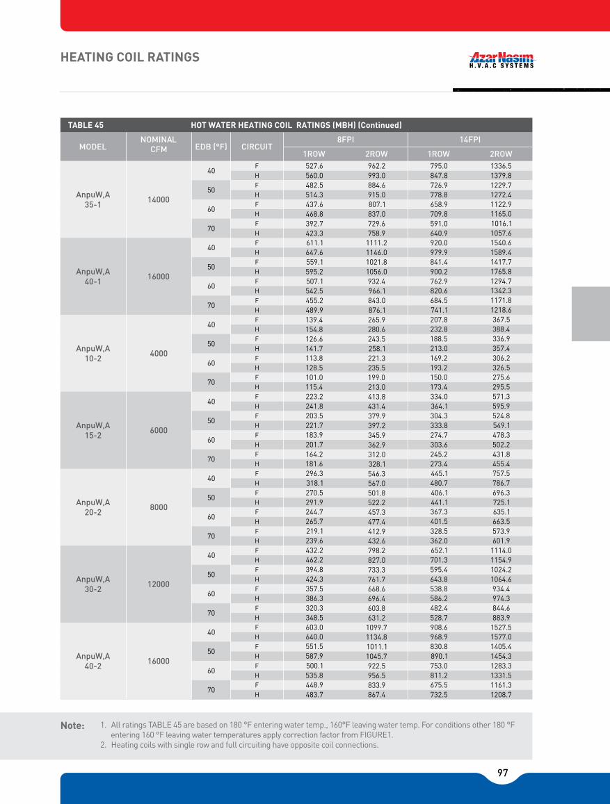
97
1. All ratings TABLE 45 are based on 180 °F entering water temp., 160°F leaving water temp. For conditions other 180 °F entering 160 °F leaving water temperatures apply correction factor from FIGURE1.
2. Heating coils with single row and full circuiting have opposite coil connections.
Note:
HEATING COIL RATINGS
1336.51379.81229.71272.41122.91165.01016.11057.61540.61589.41417.71765.81294.71342.31171.81218.6367.5388.4336.9357.4306.2326.5275.6295.5571.3595.9524.8549.1478.3502.2431.8455.4757.5786.7696.3725.1635.1663.5573.9601.91114.01154.91024.21064.6934.4974.3844.6883.91527.51577.01405.41454.31283.31331.51161.31208.7
795.0847.8726.9778.8658.9709.8591.0640.9920.0979.9841.4900.2762.9820.6684.5741.1207.8232.8188.5213.0169.2193.2150.0173.4334.0364.1304.3333.8274.7303.6245.2273.4445.1480.7406.1441.1367.3401.5328.5362.0652.1701.3595.4643.8538.8586.2482.4528.7908.6968.9830.8890.1753.0811.2675.5732.5
962.2993.0884.6915.0807.1837.0729.6758.91111.21146.01021.81056.0932.4966.1843.0876.1265.9280.6243.5258.1221.3235.5199.0213.0413.8431.4379.9397.2345.9362.9312.0328.1546.3567.0501.8522.2457.3477.4412.9432.6798.2827.0733.3761.7668.6696.4603.8631.21099.71134.81011.11045.7922.5956.5833.9867.4
527.6560.0482.5514.3437.6468.8392.7423.3611.1647.6559.1595.2507.1542.5455.2489.9139.4154.8126.6141.7113.8128.5101.0115.4223.2241.8203.5221.7183.9201.7164.2181.6296.3318.1270.5291.9244.7265.7219.1239.6432.2462.2394.8424.3357.5386.3320.3348.5603.0640.0551.5587.9500.1535.8448.9483.7
AnpuW,A35-1
AnpuW,A40-1
AnpuW,A10-2
AnpuW,A15-2
AnpuW,A20-2
AnpuW,A30-2
AnpuW,A40-2
40
50
60
70
8FPI 14FPI MODEL
NOMINAL EDB (°F) CIRCUIT
1ROW 2ROW 1ROW 2ROW
TABLE 45
FHF
F
F
H
H
H
40
50
60
70
40
50
60
70
40
50
60
70
40
50
60
70
40
50
60
70
40
50
60
70
F
F
F
F
F
F
H
H
H
H
H
H
F
F
F
F
F
F
F
F
F
F
F
F
F
F
F
F
F
F
H
H
H
H
H
H
H
H
H
H
H
H
H
H
H
H
H
H
HOT WATER HEATING COIL RATINGS (MBH) (C)
14000
16000
4000
6000
8000
12000
16000
CFM

98
1. All ratings TABLE 45 are based on 180°F entering water temp., 160°F leaving water temp. For conditions other 180°F entering 160°F leaving water temperatures apply correction factor from FIGURE1.
2. Heating coils with single row and full circuiting have opposite coil connections.
FIGURE 1HOT WATER COIL LOAD CORRECTION FACTORCorrected load = load from TABLE 45 x correction factor from FIGURE 1
Note:
HEATING COIL RATINGS
1.10
1.05
1.00
1.95
1.90
1.85
1.80
1.75
1.70
1.65
1.60
1.55
1.50
1.45
1.40
1.35
1.30
1.25
1.20
1.15
CO
RR
ECTI
ON
FA
CTO
RS
ENTERING AIR TEMP
ENTERING WATER TEMP 180°
170°
160°
150°
140°
130°
120°
110°
100°
50° 55° 60° 65° 70° 75° 80°
1930.91987.31777.51833.21624.51679.11470.71524.82332.12399.92146.92213.91961.72027.81776.51841.72733.12812.32516.12594.32299.22376.42082.22158.33058.63148.52815.42904.22572.32659.82329.02415.4
20000
24000
28000
32000
AnpuW,A50-2
AnpuW,A60-2
AnpuW,A70-2
AnpuW,A80-2
1158.51227.71060.31128.4962.31029.1864.5929.91402.61486.21283.81366.01165.21245.21046.71125.81646.61744.61507.21603.51367.91462.61229.01321.71828.31938.01673.31781.11518.51624.31364.01467.7
768.5811.0703.6745.3638.8679.7574.1614.1931.4982.8852.7903.2774.1823.7695.7744.21094.11154.51001.81061.0909.5967.6817.4874.21210.91278.21108.61174.61006.51071.2904.3967.7
40
50
60
70
8FPI 14FPI MODEL
NOMINAL EDB (°F) CIRCUIT
1ROW 2ROW 1ROW 2ROW
TABLE 45
FHF
F
F
H
H
H
40
50
60
70
40
50
60
70
40
50
60
70
F
F
F
H
H
H
F
F
F
F
F
F
F
F
F
H
H
H
H
H
H
H
H
H
HOT WATER HEATING COIL RATINGS (MBH) (C)
CFM
1391.61431.81280.01319.61168.61207.51057.11095.41683.61732.11548.81596.51413.91460.91279.11325.31975.52032.31817.31873.21659.11714.21501.01555.12198.42262.32022.22085.01846.01907.81669.81730.5

99

100
* All ratings are based on standard water velocity range (1-8 FPS).
HEATING COIL DATA
5
0.1
0.1
40
0.4
0.6
0.3
0.4
10
0.3
0.4
0.1
0.2
0.1
0.2
0.1
0.1
0.1
0.2
0.1
0.1
50
0.6
0.9
0.4
0.6
0.3
0.5
0.3
0.4
20
0.9
1.2
0.5
0.7
0.5
0.6
0.3
0.4
0.3
0.4
0.2
0.3
0.4
0.6
0.4
0.5
0.3
0.4
60
0.9
1.3
0.6
0.9
0.4
0.7
0.4
0.6
30
2
2.6
1.1
1.4
1.0
1.3
0.6
0.8
0.6
0.8
0.4
0.6
0.3
0.4
0.4
0.5
0.3
0.4
0.9
1.2
0.8
1.1
0.7
0.9
0.4
0.6
0.3
0.4
70
1.2
1.7
0.8
1.2
0.6
0.9
0.5
0.8
40
3.3
4.3
1.8
2.4
1.7
2.2
1.0
1.4
1.0
1.4
0.7
1.0
0.5
0.7
0.6
0.9
0.5
0.7
1.5
2.0
1.3
1.8
1.1
1.5
0.7
1.0
1.5
0.7
80
1.5
2.2
1.0
1.5
0.8
1.1
0.7
1.0
50
4.9
6.5
2.7
3.6
2.5
3.4
1.5
2.1
1.5
2.1
1.0
1.4
0.8
1.1
0.9
1.4
0.7
1.1
2.2
3.0
1.9
2.6
1.6
2.3
1.0
1.5
0.7
1.1
90
1.8
2.7
1.3
1.9
0.9
1.4
0.8
1.2
60
6.9
9
3.8
5
3.5
4.7
2.1
2.9
2.1
2.9
1.4
2.0
1.1
1.5
1.3
1.9
1.0
1.5
3.1
4.1
2.7
3.7
2.3
3.2
1.4
2.1
1.0
1.5
100
2.2
3.2
1.5
2.2
1.1
1.7
1.0
1.5
70
5
6.7
4.6
6.2
2.8
3.8
2.7
3.8
1.9
2.6
1.4
2.0
1.7
2.5
1.4
2.0
4.0
5.4
3.5
4.9
3.0
4.2
1.9
2.7
1.4
2.0
120
3.1
4.5
2.1
3.1
1.6
2.3
1.4
2.0
80
6.4
8.5
5.8
7.9
3.6
4.9
3.5
4.9
2.4
3.3
1.8
2.6
2.2
3.2
1.7
2.5
5.1
6.9
4.5
6.2
3.8
5.4
2.4
3.5
1.7
2.5
140
4.0
5.9
2.8
4.1
2.1
3.1
1.8
2.7
90
7.9
10.5
7.2
9.7
4.4
6.1
4.3
6.1
2.9
4.1
2.3
3.2
2.7
4.0
2.2
3.1
6.4
8.5
5.5
7.7
4.7
6.7
3.0
4.3
2.2
3.1
160
5.1
7.5
3.6
5.3
2.6
3.9
2.3
3.4
100
8.7
11.8
5.3
7.3
5.2
7.3
3.5
5.0
2.7
3.8
3.3
4.8
2.6
3.8
7.7
10.3
6.7
9.3
5.7
8.1
3.6
5.2
2.6
3.8
180
6.4
9.3
4.4
6.5
3.3
4.8
2.9
4.2
120
7.4
10.2
7.2
10.2
4.9
6.9
3.8
5.3
4.6
6.7
3.6
5.3
9.3
12.9
8.0
11.2
5.1
7.2
3.6
5.3
200
7.7
11.3
5.3
7.9
4.0
5.8
3.5
5.1
140
9.6
13.4
6.5
9.1
5.0
7.1
6.1
8.8
4.8
6.9
6.7
9.5
4.8
6.9
230
9.9
14.5
6.9
10.1
5.1
7.5
4.5
6.5
160
8.3
11.6
6.4
9.0
7.8
11.2
6.1
8.8
8.5
12.1
6.1
8.8
260
8.6
12.6
6.4
9.3
5.6
8.2
180
7.9
11.1
9.6
13.9
7.6
10.9
7.6
10.9
290
10.5
15.4
7.7
11.4
6.8
9.9
1
2
1
2
1
2
1
2
1
2
1
2
1
2
1
2
1
2
1
2
1
2
1
2
1
2
1
2
1
2
1
2
1
2
1
2
10-1
10-2
15-1
15-2
20-1
20-2
25-1
25-2
30-1
30-2
5-1
8-1
35-1
40-1
10-2
15-2
20-2
30-2
40-2
50-2
60-2
70-2
80-2
TABLE 46 HEATING COIL (FULL CIRCUIT) WATER SIDE PRESSURE DROP* (feet, water)
ROW ANPUMODEL
WATER FLOW RATE (GPM)
WATER FLOW RATE (GPM)
ROW
200
9.6
13.4
9.1
13.2
9.1
13.2
320
9.2
13.6
8.1
11.9
MODEL ANPU

101
TABLE 46A
ROW ANPUMODEL
WATER FLOW RATE (GPM)
HEATING COIL (HALF CIRCUIT) WATER SIDE PRESSURE DROP* (feet, water)
1
2
1
1
1
1
1
1
1
1
1
1
1
1
1
2
2
2
2
2
2
2
2
2
2
2
2
2
1
2
1
1
1
2
2
2
50-2
60-2
70-2
80-2
30-1
30-2
10-2
15-2
20-2
30-2
40-2
ANPUMODEL
WATER FLOW RATE (GPM)
10-110-215-115-220-120-225-125-2
35-1
40-1
5-1
8-1
200
320
180
290
160
260
140
230
120
200
100
13.4
21.2
13.2
21.4
13.2
21.4
180
14.7
24.1
90
11.1
17.5
13.9
22.5
10.9
17.7
10.9
17.7
160
13.6
22.3
11.9
19.5
80
11.6
18.4
9.0
14.2
11.2
18.2
8.8
14.3
12.1
19.3
8.8
14.3
140
14.4
23.7
10.7
17.5
9.3
15.3
70
13.4
21.2
9.1
14.4
7.1
11.1
8.8
14.3
6.9
11.2
9.5
15.2
6.9
11.2
120
15.7
25.7
10.9
17.9
8.1
13.2
7.1
11.6
60
10.2
15.7
10.2
16.1
6.9
10.9
5.3
8.4
6.7
10.8
5.3
8.5
12.9
21
11.2
17.8
7.2
11.5
5.3
8.5
100
11.3
18.5
7.9
12.9
5.8
9.5
5.1
8.3
50
11.8
17.8
7.3
11.3
7.3
11.5
5.0
7.9
3.8
6.1
4.8
7.8
3.8
6.1
10.3
15.6
9.3
14.4
8.1
12.8
5.2
8.3
3.8
6.1
90
9.3
15.3
6.5
10.6
4.8
7.9
4.2
6.9
40
8.5
12.6
7.9
11.9
4.9
7.5
4.9
7.7
3.3
5.2
2.6
4.1
3.2
5.2
2.5
4.1
6.9
10.4
6.2
9.7
5.4
8.5
3.5
5.5
2.5
4.1
80
7.5
12.4
5.3
8.6
3.9
6.4
3.4
5.6
30
9
13.3
5.0
7.5
4.7
7.1
2.9
4.5
2.9
4.6
2.0
3.1
1.5
2.4
1.
3.1
1.5
2.4
4.1
6.2
7.3
5.7
3.2
5.1
2.1
3.3
1.3
2.4
70
5.9
9.7
4.1
6.8
3.1
5.0
2.7
4.4
20
4.3
6.4
2.4
3.6
2.2
3.4
1.4
2.2
1.4
2.2
1.0
1.5
0.7
1.2
0.9
1.5
0.7
1.2
2.0
3.0
1.8
2.8
1.5
2.4
1.0
1.8
0.7
1.2
60
4.5
7.4
3.1
5.1
2.3
3.6
2.0
3.3
10
1.2
1.8
0.7
1.0
0.6
1.0
0.4
0.6
0.4
0.6
0.6
0.9
0.5
0.8
0.4
0.7
50
3.2
5.3
2.2
3.7
1.7
2.7
1.5
2.4
5
0.4
0.5
0.2
0.3
40
2.2
3.5
1.5
2.5
1.1
1.8
1.0
1.6
* All ratings are based on standard water velocity range (1-8 FPS).
HEATING COIL DATA
HEATING COIL CONNECTION SIZES
5-18-1
10-115-120-125-130-135-140-1
MODEL 1 ROW 2 ROWS MODEL 1 ROW 2 ROWS 3/4"3/4"1"
11/4"
2 x 1"2 x 1"
2 x 11/4"
2 x 11/2"
2 x 11/2"
10-215-220-230-240-250-260-270-280-2
1"11/4"
11/4"
11/2"
2 x 11/4"
2 x 11/2"
2 x 2"2 x 2"
11/4"
11/4"
2"2 x 11/2"
2 x 11/2"
2 x 2"2 x 2"2 x 2"
2 x 21/2"
1"1"
11/4"
11/2"
2 x 11/4"
2 x 11/4"
2 x 11/2"
2 x 2"2 x 2"
TABLE 47
2 x 11/2"
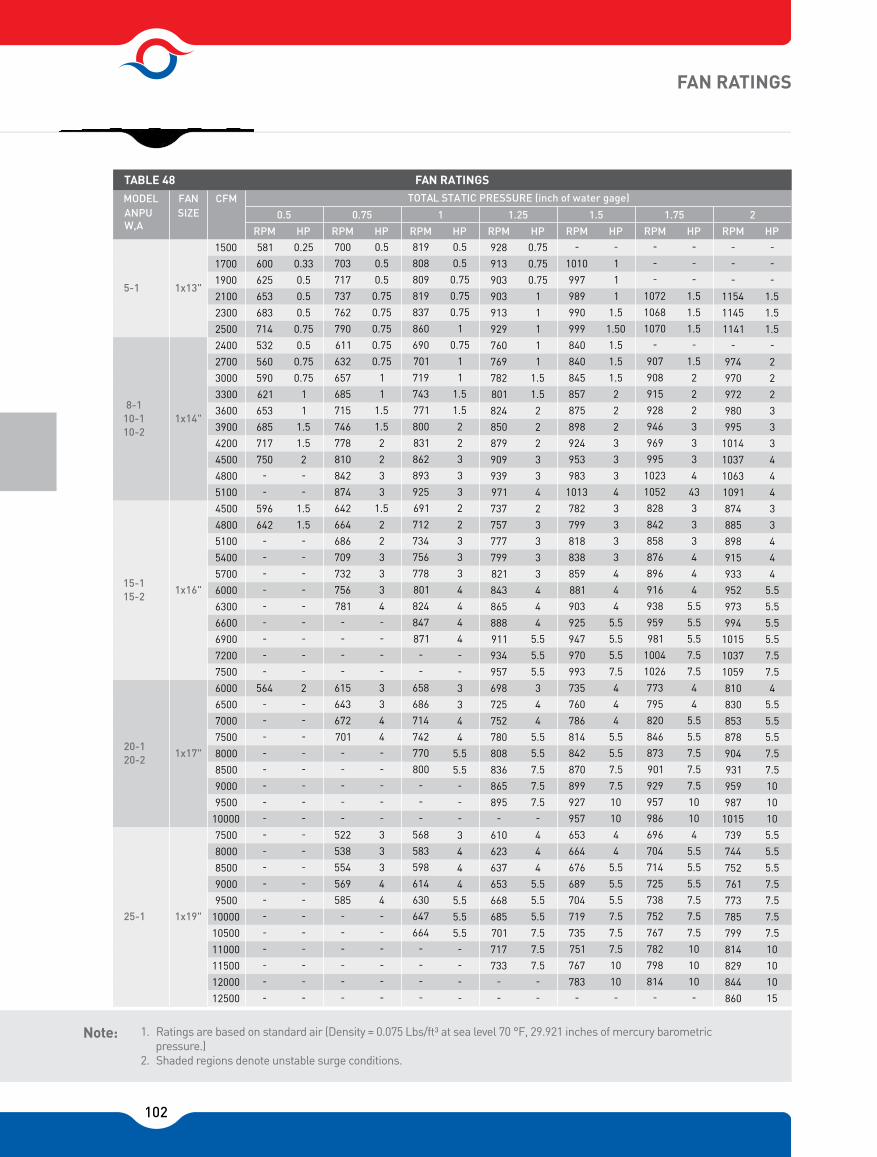
102
1. Ratings are based on standard air (Density = 0.075 Lbs/ft³ at sea level 70 °F, 29.921 inches of mercury barometric pressure.)
2. Shaded regions denote unstable surge conditions.
Note:
1500
1700
1900
2100
2300
2500
2400
2700
3000
3300
3600
3900
4200
4500
4800
5100
4500
4800
5100
5400
5700
6000
6300
6600
6900
7200
7500
6000
6500
7000
7500
8000
8500
9000
9500
10000
7500
8000
8500
9000
9500
10000
10500
11000
11500
12000
12500
-
-
-
1154
1145
1141-
974
970
972
980
995
1014
1037
1063
1091
874
885
898
915
933
952
973
994
1015
1037
1059
810
830
853
878
904
931
959
987
1015
739
744
752
761
773
785
799
814
829
844
860
-
-
-
1.5
1.5
1.5-
2
2
2
3
3
3
4
4
4
3
3
4
4
4
5.5
5.5
5.5
5.5
7.5
7.5
4
5.5
5.5
5.5
7.5
7.5
10
10
10
5.5
5.5
7.5
7.5
7.5
7.5
10
10
10
15
581
600
625
653
683
714
532
560
590
621
653
685
717
750-
-
596
642-
-
-
-
-
-
-
-
-
564-
-
-
-
-
-
-
-
-
-
-
-
-
-
-
-
-
-
-
0.25
0.33
0.5
0.5
0.5
0.75
0.5
0.75
0.75
1
1
1.5
1.5
2-
-
1.5
1.5-
-
-
-
-
-
-
-
-
2-
-
-
-
-
-
-
-
-
-
-
-
-
-
-
-
-
-
-
700
703
717
737
762
790
611
632
657
685
715
746
778
810
842
874
642
664
686
709
732
756
781-
-
-
-
615
643
672
701-
-
-
-
-
522
538
554
569
585-
-
-
-
-
-
0.5
0.5
0.5
0.75
0.75
0.75
0.75
0.75
1
1
1.5
1.5
2
2
3
3
1.5
2
2
3
3
3
4-
-
-
-
3
3
4
4-
-
-
-
-
3
3
3
4
4-
-
-
-
-
-
819
808
809
819
837
860
690
701
719
743
771
800
831
862
893
925
691
712
734
756
778
801
824
847
871-
-
658
686
714
742
770
800-
-
-
568
583
598
614
630
647
664-
-
-
-
0.5
0.5
0.75
0.75
0.75
1
0.75
1
1
1.5
1.5
2
2
3
3
3
2
2
3
3
3
4
4
4
4-
-
3
3
4
4
5.5
5.5-
-
-
3
4
4
4
5.5
5.5
5.5-
-
-
-
928
913
903
903
913
929
760
769
782
801
824
850
879
909
939
971
737
757
777
799
821
843
865
888
911
934
957
698
725
752
780
808
836
865
895-
610
623
637
653
668
685
701
717
733-
-
0.75
0.75
0.75
1
1
1
1
1
1.5
1.5
2
2
2
3
3
4
2
3
3
3
3
4
4
4
5.5
5.5
5.5
3
4
4
5.5
5.5
7.5
7.5
7.5-
4
4
4
5.5
5.5
5.5
7.5
7.5
7.5-
-
-
1010
997
989
990
999
840
840
845
857
875
898
924
953
983
1013
782
799
818
838
859
881
903
925
947
970
993
735
760
786
814
842
870
899
927
957
653
664
676
689
704
719
735
751
767
783-
-
1
1
1
1.5
1.50
1.5
1.5
1.5
2
2
2
3
3
3
4
3
3
3
3
4
4
4
5.5
5.5
5.5
7.5
4
4
4
5.5
5.5
7.5
7.5
10
10
4
4
5.5
5.5
5.5
7.5
7.5
7.5
10
10-
-
-
-
1.5
1.5
1.5-
1.5
2
2
2
3
3
3
4
43
3
3
3
4
4
4
5.5
5.5
5.5
7.5
7.5
4
4
5.5
5.5
7.5
7.5
7.5
10
10
4
5.5
5.5
5.5
7.5
7.5
7.5
10
10
10-
-
-
-
1072
1068
1070-
907
908
915
928
946
969
995
1023
1052
828
842
858
876
896
916
938
959
981
1004
1026
773
795
820
846
873
901
929
957
986
696
704
714
725
738
752
767
782
798
814-
1x13" 5-1
1x14" 8-1
10-1 10-2
1x16" 15-1 15-2
1x17" 20-1 20-2
1x19" 25-1
0.5 0.75 1 1.25 1.5 1.75 2
MODEL ANPU
FAN SIZE
CFM
RPM HP
TABLE 48 TOTAL STATIC PRESSURE (inch of water gage)
RPM RPM RPM RPM RPM RPM HP HP HP HP HP HP
FAN RATINGS
5.5
W,A
FAN RATINGS
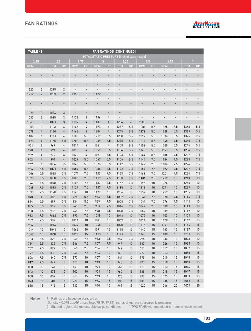
103
1. Ratings are based on standard air (Density = 0.075 Lbs/ft³ at sea level 70 °F, 29.921 inches of mercury barometric pressure.)2. Shaded regions denote unstable surge conditions. * TWO FANS with one electric motor on each model.
Note:
FAN RATINGS
-
-
-
-
1220
1212-
-
-
1028
1033
1043
1058
1079
1102
1128
921
928
939
953
969
986
1006
1026
1047
1068
1090
848
864
885
908
933
959
986
1014
1042
783
784
789
797
806
817
830
843
858
873
888
-
-
-
-
2
2-
-
-
3
3
3
3
4
4
4
3
4
4
4
4
5.5
5.5
5.5
7.5
7.5
7.5
4
5.5
5.5
7.5
7.5
7.5
10
10
15
5.5
5.5
7.5
7.5
7.5
7.5
10
10
10
15
15
-
-
-
-
1295
1283-
-
-
1084
1085
1091
1103
1120
1141
1165
967
971
979
991
1004
1021
1038
1058
1078
1098
1120
886
899
917
938
9662
987
1014
1041
1068
826
825
827
832
840
849
861
873
887
901
916
-
-
-
-
2
2-
-
-
3
3
3
4
4
4
5.5
4
4
4
4
5.5
5.5
5.5
7.5
7.5
7.5
7.5
5.5
5.5
7.5
7.5
7.5
10
10
10
15
7.5
7.5
7.5
7.5
7.5
10
10
10
10
15
15
-
-
-
-
-
1353-
-
-
-
1136
1139
1148
1162
1180
1202
1014
1015
1020
1029
1040
1054
1071
1088
1108
1127
1148
925
934
949
968
990
1014
1039
1066
1093
869
866
866
868
873
881
891
902
915
928
943
-
-
-
-
-
3-
-
-
-
3
4
4
4
5.5
5.5
4
4
4
5.5
5.5
5.5
7.5
7.5
7.5
7.5
10
5.5
5.5
7.5
7.5
7.5
10
10
10
15
7.5
7.5
7.5
7.5
10
10
10
10
15
15
15
-
-
-
-
-
1422-
-
-
-
1186
1187
1193
1204
1219
1239
1061
1059
1061
1067
1076
1088
1103
1119
1137
1157
1177
964
969
981
998
1018
1041
1065
1091
1118
913
907
904
904
907
913
921
931
943
956
970
-
-
-
-
-
3-
-
-
-
4
4
4
4
5.5
5.5
4
5.5
5.5
5.5
5.5
7.5
7.5
7.5
7.5
7.5
10
5.5
7.5
7.5
7.5
10
10
10
15
15
7.5
7.5
10
10
10
10
10
15
15
15
15
-
-
-
-
-
-
-
-
-
�
-
1234
1237
1245
1258
1275
1108
1104
1103
1106
1112
1122
1135
1150
1167
1185
1204
1002
1005
1014
1028
1046
1067
1090
1115
1141
954
947
942
940
941
945
951
960
970
982
995
-
-
-
-
-
-
-
-
-
-
-
4
5.5
5.5
5.5
5.5
5.5
5.5
5.5
5.5
5.5
7.5
7.5
7.5
7.5
10
10
7.5
7.5
7.5
7.5
10
10
10
15
15
7.5
10
10
10
10
10
15
15
15
15
-
-
-
-
-
-
-
-
-
-
-
1280
1281
1278
1297
1311
1156
1148
1144
1144
1149
1157
1168
1181
1196
1213
1232
1041
1041
1047
1059
1075
1094
1116
1140
1165
996
987
981
977
975
977
981
988
997
1008
1020
-
-
-
-
-
-
-
-
-
-
-
4
5.5
5.5
5.5
5.5
5.5
5.5
5.5
7.5
7.5
7.5
7.5
7.5
10
10
10
7.5
7.5
7.5
10
10
10
15
15
15
10
10
10
10
10
15
15
15
15
15
15
-
-
-
-
-
-
-
-
-
-
-
-
1325
1328
1336
1348
1200
1191
1185
1184
1186
1192
1201
1212
1226
1241
1259
1078
1076
1080
1089
1103
1120
1141
1163
1188
1034
1026
1019
1013
1010
1010
1013
1018
1025
1035
1046
-
-
-
-
-
-
-
-
-
-
-
-
5.5
5.5
5.5
7.5
5.5
5.5
7.5
7.5
7.5
7.5
7.5
10
10
10
10
7.5
7.5
10
10
10
10
15
15
15
10
10
10
10
15
15
15
15
15
15
20
-
-
-
-
-
-
-
-
-
-
-
-
1368
1369
1375
1385
1244
1234
1227
1223
1224
1227
1234
1243
1255
1269
1285
1116
1111
1113
1119
1131
1147
1166
1187
1211
1073
1065
1057
1050
1045
1043
1044
1047
1053
1061
1071
-
-
-
-
-
-
-
-
-
-
-
-
5.5
5.5
7.5
7.5
5.5
7.5
7.5
7.5
7.5
7.5
7.5
10
10
10
10
7.5
10
10
10
10
15
15
15
15
10
10
15
15
15
15
15
15
15
15
20
15
2.25 2.5 2.75 3 3.25 3.5 3.75 4
RPM HP
TABLE 48 TOTAL STATIC PRESSURE (inch of water gage)
RPM RPM RPM RPM RPM RPM HP HP HP HP HP HP RPM HP
FAN RATINGS NTINE

104
FAN RATINGS
479493507522536550564---------------------------------------------------
2333344---------------------------------------------------
533546559573587601615629643657672686701--------------------
569577585593---------------------
583594605618631644658686700714728742756770785800-----------------
614622630639647658664------------------
333444
5.55.5
7.57.57.5
-------------------7.57.51010---------------------
344445.55.55.57.57.57.5
10101015
----------------10101010101015------------------
633641650661672685698711725738752766780794808822836851865880895------------
653660668676685693701709717725733--------------
4445.55.57.55.57.57.57.57.510101010151515151515------�-----1010101015151515151515-----�--------
6866916977047147247357477607337868008148288428568708848999139279429579729871003-------
689697704712719727735743751759767775783791-----------
45.55.55.55.57.57.57.57.51010101010151515151515202020202025-------1010151515151515151520202020-----------
737739742747755763773783795807820833846859873887901915929943957972986100110151030-------
725732738745752760767775782790798806814822-----------
5.55.55.57.57.57.57.57.5101010101015151515151520202020202525-------1515151515151515202020202020-----------
78878778779079580281081983084185386587889190491893194595997398710011015102910431058107210871101111611311147-
761767773779785792799806814821829837844852860869877885893902910918927936-
5.57.57.57.57.57.57.510101010101515151515152020202020252525253030303030-151515151515152020202020202525252525303030303030-
900095001000010500110001150012000125001300013500140001450015000155001600016500170001750018000185001900019500200002050021000215002200022500230002350024000245002500018000185001900019500200002050021000215002200022500230002350024000245002500025500260002650027000275002800028500290002950030000
2*x1
9"2*
x17"
30-135-130-240-140-250-2
60-2
0.5 0.75 1 1.25 1.5 1.75 2
MODEL ANPU
FAN SIZE
CFM
RPM HP
TABLE 48 TOTAL STATIC PRESSURE (inch of water gage)
RPM RPM RPM RPM RPM RPM HP HP HP HP HP HP
FAN RATINGS (Continued)
5.5
7.5
-
10
-
W,A
1. Ratings are based on standard air (Density = 0.075 Lbs/ft³ at sea level 70 °F, 29.921 inches of mercury barometric pressure.)2. Shaded regions denote unstable surge conditions. *TWO FANS with one electric motor on each model.
Note:

105
FAN RATINGS
839 7.5 889 7.5 - - - - - - - - - - - - 835 7.5 884 7.5 931 10 977 10 - - - - - - - - 834 7.5 881 7.5 926 10 972 10 1017 10 1062 15 - - - - 835 7.5 879 10 924 10 968 10 1010 15 1053 15 - - - - 838 7.5 880 10 922 10 964 10 1006 15 1047 15 1088 15 1128 15 842 10 882 10 923 10 963 10 1003 15 1043 15 1082 15 1121 15 848 10 886 10 925 10 964 15 1002 15 1041 15 1078 15 1116 15 856 10 892 10 929 15 966 15 1003 15 1040 15 1077 15 1113 15 864 10 899 10 934 15 969 15 1005 15 1041 15 1076 15 1111 20 874 10 907 15 941 15 975 15 1009 15 1043 15 1077 15 1111 20 885 15 917 15 949 15 981 15 1014 15 1047 15 1080 20 1113 20 896 15 927 15 958 15 989 15 1021 15 1053 15 1084 20 1115 20 908 15 938 15 968 15 998 15 1028 15 1059 20 1089 20 1119 20 920 15 950 15 979 15 1008 15 1037 20 1066 20 1095 20 1125 20 933 15 962 15 990 15 1018 20 1046 20 1075 20 1103 20 1131 20 946 15 974 15 1002 20 1029 20 1056 20 1084 20 1111 20 1138 20 959 15 987 20 1014 20 1041 20 1067 20 1094 20 1120 20 1147 25 973 20 1000 20 1027 20 1053 20 1079 20 1104 20 1130 25 1156 25 986 20 1014 20 1039 20 1065 20 1090 20 1116 25 1141 25 1166 25
1000 20 1027 20 1053 20 1078 25 1103 25 1127 25 1152 25 1176 25 1014 20 1041 20 1066 25 1091 25 1115 25 1140 25 1163 25 1187 25 1028 20 1054 25 1079 25 1104 25 1128 25 1152 25 1175 30 1199 30 1042 25 1068 25 1093 25 1118 25 1141 25 1165 30 1188 30 1211 30 1056 25 1082 25 1107 25 1131 25 1155 30 1178 30 1201 30 1223 30 1070 25 1096 25 1121 30 1145 30 1168 30 1192 30 1214 30 1236 30 1084 25 1110 30 1135 30 1159 30 1182 30 1205 30 1227 40 1249 40 1098 30 1124 30 1149 30 1173 30 1196 30 1219 40 1240 40 1262 40 1113 30 1139 30 1163 30 1187 30 1210 40 1233 40 1254 40 1275 40 1127 30 1153 30 1177 30 1201 30 1223 40 1246 40 1268 40 1289 40 1142 30 1167 30 1191 40 1215 40 1237 40 1260 40 1281 40 1302 40 1157 30 1182 40 1205 40 1229 40 1251 40 1274 40 1295 40 1315 40 1171 40 1196 40 1220 40 1243 40 1265 40 1288 40 1308 40 1329 50
- - 1211 40 1234 40 1258 40 1279 40 1301 40 1322 50 1342 50 797 15 832 15 868 15 904 20 940 20 977 20 1013 25 1050 25 801 15 836 15 870 20 905 20 940 20 967 20 1011 25 1047 25 806 15 840 15 873 20 907 20 941 20 975 20 1010 25 1045 25 812 15 844 20 877 20 910 20 943 20 976 25 1010 25 1044 25 817 15 849 20 881 20 913 20 945 20 977 25 1010 25 1043 25 823 20 855 20 886 20 917 20 948 25 979 25 1011 25 1043 25 830 20 861 20 891 20 921 20 951 25 981 25 1013 25 1044 30 837 20 867 20 896 20 926 25 955 25 985 25 1015 25 1045 30 843 20 873 20 902 20 931 25 960 25 988 25 1018 30 1047 30 851 20 880 20 908 25 937 25 965 25 993 25 1021 30 1050 30 858 20 887 25 915 25 943 25 970 25 997 30 1025 30 1053 30 865 20 894 25 922 25 949 25 976 30 1003 30 1030 30 1057 30 873 25 901 25 928 25 956 25 982 30 1008 30 1035 30 1061 30 881 25 909 25 936 25 962 25 988 30 1014 30 1040 30 1066 30 888 25 916 25 943 30 970 30 995 30 1020 30 1046 30 1071 40 896 25 924 25 950 30 977 30 1002 30 1027 30 1052 40 1077 40 904 25 932 30 958 30 984 30 1009 30 1034 30 1058 40 1083 40 912 30 939 30 965 30 991 30 1016 30 1040 40 1065 40 1089 40 920 30 947 30 973 30 999 30 1023 40 1047 40 1071 40 1095 40 928 30 955 30 980 30 1006 40 1030 40 1055 40 1078 40 1102 40 936 30 963 30 988 30 1013 40 1038 40 1062 40 1085 40 1108 40 944 30 970 40 996 40 1021 40 1045 40 1069 40 1092 40 1115 40 953 30 978 40 1003 40 1028 40 1052 40 1076 40 1099 40 1122 50 961 40 986 40 1010 40 1035 40 1059 40 1083 40 1106 40 1129 50
- - 993 40 1018 40 1042 40 1066 40 1090 40 1113 50 1135 50
RPM HP
TABLE 48 TOTAL STATIC PRESSURE (inch of water gage)
RPM RPM RPM RPM RPM RPM HP HP HP HP HP HP RPM HP
2.25 2.5 2.75 3 3.25 3.5 3.75 4
FAN RATINGS (Continued)
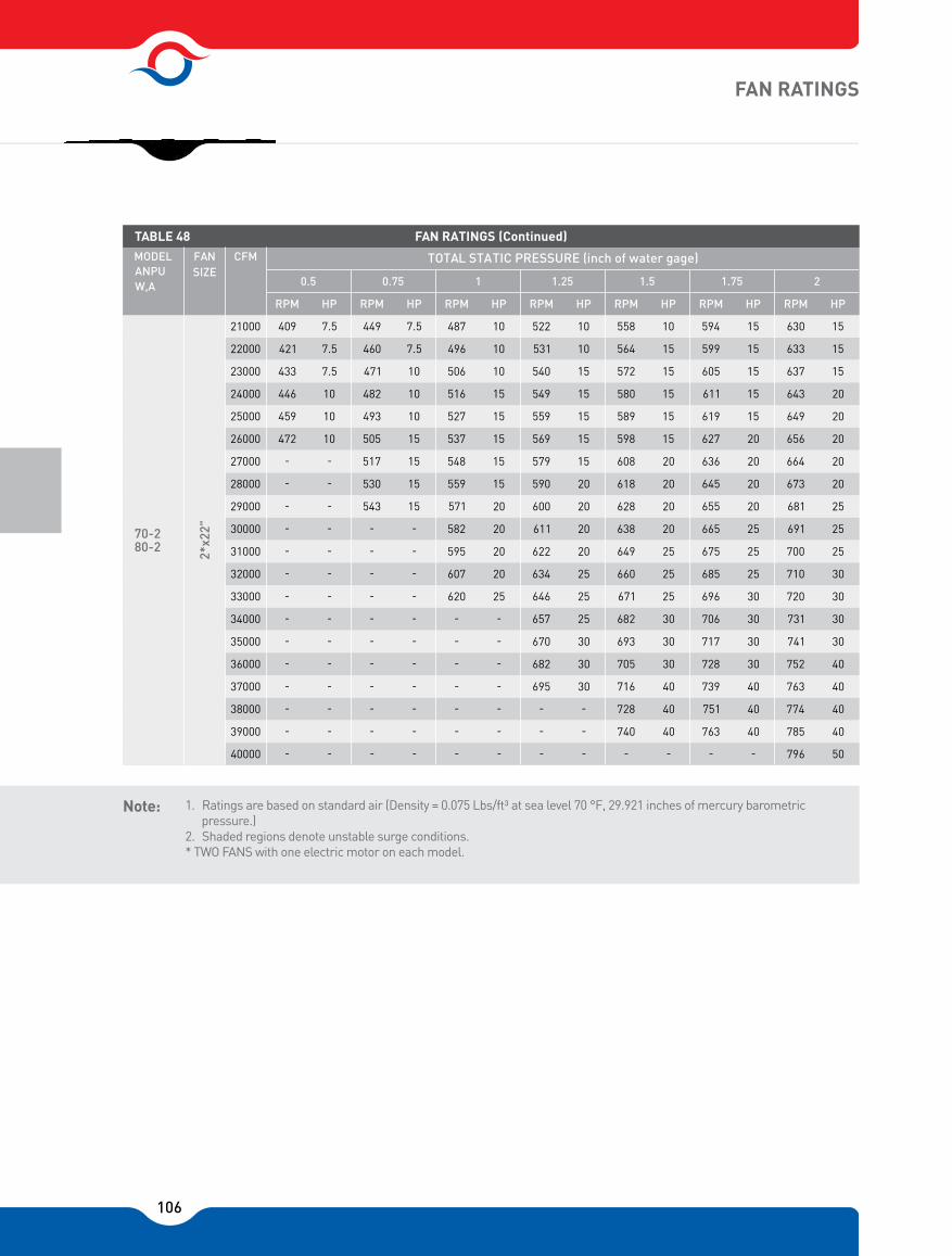
106
FAN RATINGS
1. Ratings are based on standard air (Density = 0.075 Lbs/ft³ at sea level 70 °F, 29.921 inches of mercury barometric pressure.)
2. Shaded regions denote unstable surge conditions.* TWO FANS with one electric motor on each model.
Note:
21000 409 7.5 449 7.5 487 10 522 10 558 10 594 15 630 15
22000 421 7.5 460 7.5 496 10 531 10 564 15 599 15 633 15
23000 433 7.5 471 10 506 10 540 15 572 15 605 15 637 15
24000 446 10 482 10 516 15 549 15 580 15 611 15 643 20
25000 459 10 493 10 527 15 559 15 589 15 619 15 649 20
26000 472 10 505 15 537 15 569 15 598 15 627 20 656 20
27000 - - 517 15 548 15 579 15 608 20 636 20 664 20
28000 - - 530 15 559 15 590 20 618 20 645 20 673 20
29000 - - 543 15 571 20 600 20 628 20 655 20 681 25
30000 - - - - 582 20 611 20 638 20 665 25 691 25
31000 - - - - 595 20 622 20 649 25 675 25 700 25
32000 - - - - 607 20 634 25 660 25 685 25 710 30
33000 - - - - 620 25 646 25 671 25 696 30 720 30
34000 - - - - - - 657 25 682 30 706 30 731 30
35000 - - - - - - 670 30 693 30 717 30 741 30
36000 - - - - - - 682 30 705 30 728 30 752 40
37000 - - - - - - 695 30 716 40 739 40 763 40
38000 - - - - - - - - 728 40 751 40 774 40
39000 - - - - - - - - 740 40 763 40 785 40
70-2 80-2
2*x2
2"
40000 - - - - - - - - - - - - 796 50
0.5 0.75 1 1.25 1.5 1.75 2
MODEL ANPU
FAN SIZE
CFM
RPM HP
TABLE 48
TOTAL STATIC PRESSURE (inch of water gage)
RPM RPM RPM RPM RPM RPM HP HP HP HP HP HP
FAN RATINGS (Continued)
W,A

107
666 15 702 20 737 20 772 20 807 25 841 25 875 25 908 30
667 20 702 20 736 20 770 20 803 25 837 25 870 30 902 30
670 20 703 20 736 20 769 25 801 25 833 25 865 30 897 30
674 20 706 20 737 25 769 25 800 25 831 30 862 30 893 30
679 20 709 20 740 25 770 25 800 25 830 30 860 30 890 30
685 20 714 25 743 25 772 25 801 30 830 30 859 30 888 40
692 25 719 25 747 25 775 25 803 30 831 30 859 30 887 40
699 25 726 25 753 25 780 30 806 30 833 30 860 40 887 40
707 25 733 25 759 30 785 30 811 30 836 40 862 40 888 40
716 25 741 30 766 30 791 30 815 30 840 40 865 40 890 40
725 30 749 30 773 30 797 40 821 40 845 40 870 40 894 40
734 30 758 30 781 30 804 40 828 40 851 40 874 40 898 40
744 30 767 30 790 40 812 40 835 40 858 40 880 40 903 50
754 30 777 40 799 40 820 40 843 40 865 40 887 50 909 50
764 40 787 40 808 40 829 40 851 40 872 50 894 50 915 50
774 40 797 40 818 40 838 40 859 50 880 50 901 50 922 50
785 40 807 40 828 40 848 50 869 50 889 50 909 50 930 50
796 40 818 40 838 50 858 50 878 50 898 50 918 50 938 60
807 50 828 50 848 50 868 50 888 50 907 50 927 60 946 60
818 50 839 50 859 50 878 50 898 60 917 60 936 60 955 60
2.25 2.5 2.75 3 3.25 3.5 3.75 4
RPM HP
TABLE 48
TOTAL STATIC PRESSURE (inch of water gage)
RPM RPM RPM RPM RPM RPM HP HP HP HP HP HP RPM HP
FAN RATINGS (Continued)

108
1. For ducted applications of AzarNasim Packaged Units with electric heating coils, an automatic air flow switch will be supplied separately. Before starting up the unit, the air flow switch must be installed in the duct and wired to the electrical control panel as per electrical wiring diagram instructions. Failure to do so will cause damage to the electric heating elements and void the guarantee.
2. Before switching unit to winter season application, system pump down must be performed.
Note:
* 380 V - 3 Phase - 50 Cycle, star connection
ELECTRIC HEATING COIL DATA
TABLE 49
AVAILABLE CAPACITIES (KW)
NUMBER OF CIRCUITES
NUMBER OF CIRCUITES x KW STAGES
12
18
24
30
36
42
48
54
60
66
72
78
84
90
96
1
1
1
2
2
3
3
3
3
3
3
4
4
4
4
1 x 12
1 x 18
1 x 24
(1 x 12) + (1 x 18)
(2 x 18)
(2 x 12) + (1 x 18)
(1 x 12) + (2 x 18)
3 x 18
(2 x 18) + (1 x 24)
2 x 18 + 1 x 24
3 x 24
(1 x 12) + (1 x 18) + 2 x 24)
(2 x 18) + (2 x 24)
(1 x 18) + (3 x 24)
4 x 24
1
1
1
2
2
3
3
3
3
3
3
4
4
4
4
THERMOSTAT
ELECTRIC HEATING COIL SPECIFICATION
ELECTRICAL ELEMENT POWER (KW) AMPS *
12
18
24
18.1
27.2
36.6
TABLE 50 ELECTRIC HEATING ELEMENT DATA
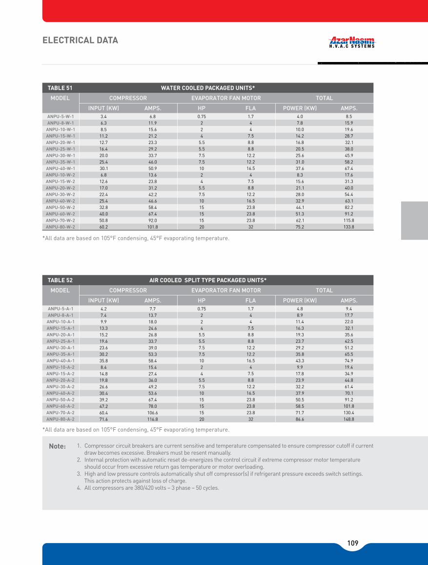
109
9.417.722.032.135.642.551.265.574.919.434.944.861.470.191.2101.8130.4148.8
4.88.911.416.319.323.729.235.843.39.917.823.932.237.950.558.571.786.6
1.7447.58.88.812.212.216.547.58.812.216.523.823.823.832
0.752245.55.57.57.510245.57.51015151520
7.713.718.024.626.833.739.053.358.415.427.436.049.253.667.478.0106.6116.8
4.27.49.913.315.219.623.630.235.88.414.819.826.630.439.247.260.471.6
COMPRESSOR EVAPORATOR FAN MOTOR TOTAL MODEL
INPUT (KW) HP FLA POWER (KW) AMPS.
TABLE 52
AMPS.
AIR COOLED SPLIT TYPE PACKAGED UNITS*
ANPU-5-A-1ANPU-8-A-1
ANPU-10-A-1ANPU-15-A-1ANPU-20-A-1ANPU-25-A-1ANPU-30-A-1ANPU-35-A-1ANPU-40-A-1ANPU-10-A-2ANPU-15-A-2ANPU-20-A-2ANPU-30-A-2ANPU-40-A-2ANPU-50-A-2ANPU-60-A-2ANPU-70-A-2ANPU-80-A-2
1. Compressor circuit breakers are current sensitive and temperature compensated to ensure compressor cutoff if current draw becomes excessive. Breakers must be resent manually.
2. Internal protection with automatic reset de-energizes the control circuit if extreme compressor motor temperature should occur from excessive return gas temperature or motor overloading.
3. High and low pressure controls automatically shut off compressor(s) if refrigerant pressure exceeds switch settings. This action protects against loss of charge.
4. All compressors are 380/420 volts � 3 phase � 50 cycles.
Note:
*All data are based on 105°F condensing, 45°F evaporating temperature.
*All data are based on 105°F condensing, 45°F evaporating temperature.
ELECTRICAL DATA
8.515.919.628.732.138.045.958.267.417.631.340.054.463.182.291.2115.8133.8
COMPRESSOR EVAPORATOR FAN MOTOR TOTAL MODEL
INPUT (KW) HP FLA POWER (KW) AMPS. 4.07.810.014.216.820.525.631.037.68.315.621.128.032.944.151.362.175.2
1.7447.58.88.812.212.216.547.58.812.216.523.823.823.832
0.752245.55.57.57.510245.57.51015151520
6.811.915.621.223.329.233.746.050.913.623.831.242.246.658.467.492.0101.8
3.46.38.511.212.716.420.025.430.16.812.617.022.425.432.840.050.860.2
ANPU-5-W-1ANPU-8-W-1
ANPU-20-W-1ANPU-25-W-1ANPU-30-W-1ANPU-35-W-1ANPU-40-W-1
ANPU-20-W-2ANPU-30-W-2ANPU-40-W-2ANPU-50-W-2ANPU-60-W-2ANPU-70-W-2ANPU-80-W-2
TABLE 51
AMPS.
WATER COOLED PACKAGED UNITS*
ANPU-10-W-1ANPU-15-W-1
ANPU-10-W-2ANPU-15-W-2
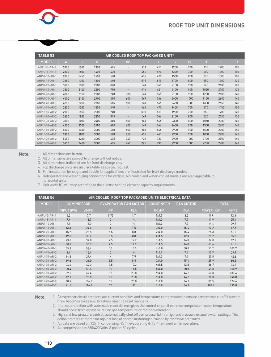
110
1. All dimensions are in mm.2. All dimensions are subject to change without notice.3. All dimensions indicated are for front discharge only.4. Top discharge units are also available as special request.5. Fan installation for single and double fan applications are illustrated for front discharge models.6. Refrigerator and water piping connections for vertical, air-cooled and water-cooled models are also applicable to
horizontal units.7. Unit width (C) will vary according to the electric heating element capacity requirements.
Note:
1. Compressor circuit breakers are current sensitive and temperature compensated to ensure compressor cutoff if current draw becomes excessive. Breakers must be reset manually.
2. Internal protection with automatic reset de-energizes the control circuit if extreme compressor motor temperature should occur from excessive return gas temperature or motor overloading.
3. High and low pressure control, automatically shut off compressor(s) if refrigerant pressure exceed switch settings. This action protects compressor against loss of charge or damaged caused by excessive pressures.
4. All data are based on 125 °F condensing, 45 °F evaporating & 95 °F ambient air temperature.5. All compressor are 380/420 Volts-3 phase-50 cycles.
Note:
ROOF TOP UNIT DIMENSIONS
100
100
100
120
120
120
140
140
140
100
120
120
140
140
140
140
140
140
A B C D DD E F G GG H L J
1200
1300
1500
1700
2100
2100
2100
2600
2650
1450
1900
2150
2300
2600
2900
2900
2900
2900
450
600
650
850
860
1050
1200
1150
1300
670
750
820
1050
1350
1500
1800
2100
2250
700
700
800
800
900
900
900
1000
1000
700
700
800
800
900
900
900
1000
1000
1200
1300
1500
1700
2100
2100
2100
2600
2650
1450
1900
2150
2300
2600
2900
2900
2900
2900
415
470
470
519
566
621
566
566
566
470
519
566
566
566
566
621
730
730
411
466
466
515
561
616
561
561
561
466
515
561
561
561
561
616
725
725
-
-
-
-
-
-
500
600
600-
-
-
500
600
600
650
740
740
445
470
570
640
820
790
240
490
515
540
740
845
340
490
640
560
405
405
1300
1400
1600
1800
2200
2200
2200
2700
2750
1550
2000
2250
2400
2700
3000
3000
3000
3000
1200
1400
1450
1700
1800
2100
2150
2100
2250
1500
1650
1800
2000
2300
2450
2800
3250
3400
2800
2800
2800
3350
3600
3800
4000
4000
4250
2850
2900
3600
3800
4150
5300
5300
5450
5450
MODEL
TABLE 53
ANPU-5-AR-1
ANPU-8-AR-1
ANPU-10-AR-1
ANPU-15-AR-1
ANPU-20-AR-1
ANPU-25-AR-1
ANPU-30-AR-1
ANPU-35-AR-1
ANPU-40-AR-1
ANPU-10-AR-2
ANPU-15-AR-2
ANPU-20-AR-2
ANPU-30-AR-2
ANPU-40-AR-2
ANPU-50-AR-2
ANPU-60-AR-2
ANPU-70-AR-2
ANPU-80-AR-2
AIR COOLED ROOF TOP PACKAGED UNIT*
TABLE 54
12.625.429.747.551.055.367.281.5105.727.142.660.274.2100.9137.4148.0176.6195.0
CONDENSER FAN MOTOR
NOxHP FLA
5.911.914.422.225.328.234.841.455.212.920.829.936.749.868.376.389.5104.4
3.27.77.715.415.412.816.016.030.87.77.715.412.830.846.246.246.246.2
1.7447.58.88.812.212.216.547.58.812.216.523.823.823.832
0.752245.55.57.57.510245.57.51015151520
7.713.718.024.626.833.739.053.358.415.427.436.049.253.667.478.0106.6116.8
4.27.49.913.315.219.623.630.235.88.414.819.826.630.439.247.260.471.6
COMPRESSOR EVAPORATOR FAN MOTOR TOTAL MODEL
INPUT (KW) HP FLA POWER (KW) AMPS. AMPS.
AIR COOLED ROOF TOP PACKAGED UNITS ELECTRICAL DATA
ANPU-5-AR-1ANPU-8-AR-1
ANPU-10-AR-1ANPU-15-AR-1ANPU-20-AR-1ANPU-25-AR-1ANPU-30-AR-1ANPU-35-AR-1ANPU-40-AR-1ANPU-10-AR-2ANPU-15-AR-2ANPU-20-AR-2ANPU-30-AR-2ANPU-40-AR-2ANPU-50-AR-2ANPU-60-AR-2ANPU-70-AR-2ANPU-80-AR-2
1x1.51x4.01x4.02x4.02x4.04x1.55x1.55x1.54x4.01x4.01x4.02x4.04x1.54x4.06x4.06x4.06x4.06x4.0

111
FFIGURE 2. SINGLE FAN MODELS
FFIGURE 3. DOUBLE FAN MODELS
ROOF TOP UNIT DIMENSIONS
ELEC. CONTROLPANEL
COMP.
SECTION
CONDENSER SECTION
HOT WTER INLET
HOT WTER
OUTLET
FAN & COIL
SECTION
COIL
SECTION
B
G
CA
GG
G
H
ED J
ELEC. CONTROLPANEL
COMP.
SECTION
CONDENSER SECTION
HOT WTER INLET
HOT WTER
OUTLET
FAN & COIL
SECTION
COIL
SECTION
B
G
CA
GG
G
H
J
EDD
ED
AIR FLOW
SERVICE AREA

112
1. All dimensions are in mm.2. All dimensions are subject to change without notice.
1. All dimensions are in mm.2. All dimensions are subject to change without notice.3. All dimensions indicated are for front discharge only.4. Top discharge units are also available as special request.5. Fan installation for single and double fan applications are illustrated for front discharge models.6. Refrigerator and water piping connections for vertical, air-cooled and water-cooled models are also applicable to
horizontal units.7. Unit width (C) will vary according to the electric heating element capacity requirements
Note:
VERTICAL UNIT DIMENSIONS
1800
2000
2000
2300
2450
3000
3000
3000
3200
2100
2200
2400
3100
3350
3500
3900
4300
4500
1300
1400
1600
1800
2200
2200
2200
2700
2750
1550
2000
2250
2400
2700
3000
3000
4000
4000
100
100
100
120
120
120
140
140
140
100
120
120
140
140
140
140
140
A B C D DD E F G GG H L J
1200
1300
1500
1700
2100
2100
2100
2600
2650
1450
1900
2150
2300
2600
2900
2900
2900
2900
450
600
650
850
860
1050
1200
1150
1300
670
750
820
1050
1350
1500
1800
2100
2250
700
700
800
800
900
900
900
1000
1000
700
700
800
800
900
900
900
1000
1000
1200
1300
1500
1700
2100
2100
2100
2600
2650
1450
1900
2150
2300
2600
2900
2900
2900
2900
415
470
470
519
566
621
566
566
566
470
519
566
566
566
566
621
730
730
411
466
466
515
561
616
561
561
561
466
515
561
561
561
561
616
725
725
-
-
-
-
-
-
500
600
600-
-
-
500
600
600
650
740
740
445
470
570
640
820
790
240
490
515
540
740
845
340
490
640
560
405
405
MODEL
TABLE 56
800
850
850
900
1000
1000
1000
1000
1100
850
900
1000
1000
1000
1000
1000
1200
1200
ANPU-5-AV-1
ANPU-8-AV-1
ANPU-10-AV-1
ANPU-15-AV-1
ANPU-20-AV-1
ANPU-25-AV-1
ANPU-30-AV-1
ANPU-35-AV-1
ANPU-40-AV-1
ANPU-10-AV-2
ANPU-15-AV-2
ANPU-20-AV-2
ANPU-30-AV-2
ANPU-40-AV-2
ANPU-50-AV-2
ANPU-60-AV-2
ANPU-70-AV-2
ANPU-80-AV-2
AIR COOLED (SPLIT TYPE)
120
900
900
900
900
1050
1050
1050
1100
1200
900
900
1100
1200
1300
1300
1300
1400
1500
1800
2000
2000
2300
2450
3000
3000
3000
3200
2100
2200
2400
3100
3350
3500
3900
4300
4500
1300
1400
1600
1800
2200
2200
2200
2700
2750
1550
2000
2250
2400
2700
3000
3000
4000
4000
100
100
100
120
120
120
140
140
140
100
120
120
140
140
140
140
140
A B C D DD E F G GG H L J
1200
1300
1500
1700
2100
2100
2100
2600
2650
1450
1900
2150
2300
2600
2900
2900
2900
2900
450
600
650
850
860
1050
1200
1150
1300
670
750
820
1050
1350
1500
1800
2100
2250
700
700
800
800
900
900
900
1000
1000
700
700
800
800
900
900
900
1000
1000
1200
1300
1500
1700
2100
2100
2100
2600
2650
1450
1900
2150
2300
2600
2900
2900
2900
2900
415
470
470
519
566
621
566
566
566
470
519
566
566
566
566
621
730
730
411
466
466
515
561
616
561
561
561
466
515
561
561
561
561
616
725
725
-
-
-
-
-
-
500
600
600-
-
-
500
600
600
650
740
740
445
470
570
640
820
790
240
490
515
540
740
845
340
490
640
560
405
405
MODEL
TABLE 55
ANPU-5-WV-1
ANPU-8-WV-1
ANPU-10-WV-1
ANPU-15-WV-1
ANPU-20-WV-1
ANPU-25-WV-1
ANPU-30-WV-1
ANPU-35-WV-1
ANPU-40-WV-1
ANPU-10-WV-2
ANPU-15-WV-2
ANPU-20-WV-2
ANPU-30-WV-2
ANPU-40-WV-2
ANPU-50-WV-2
ANPU-60-WV-2
ANPU-70-WV-2
ANPU-80-WV-2
WATER COOLED
120

113
FIGURE 4. SINGLE FAN TYPE FIGURE 5. DOUBLE FAN TYPE
FIGURE 6. VERTICAL PACKAGED UNITS CONNECTIONS
VERTICAL UNIT DIMENSIONS
GGG
C
B
GC
GGG
C
B
GC
SAN SECTION
& ELEC.
CONTROL PANEL
HOT WATER
OUTLET
HOT WATER
INLET
COIL
SECTION
COMP. SECTIONJ
L
H
EDD
ED
SAN SECTION
& ELEC.
CONTROL PANEL
HOT WATER
OUTLET
HOT WATER
INLET
COIL
SECTION
COMP. SECTIONJ
L
H
ED
HOT WATER OUT
HOT WATER IN
INLET GRILLE
ACCESS TO COMPRESSOR
DUCTLESS INSTALLATION
UPBLAST DISCHARGE
OUTLET
INLET
DUCTED INSTALLATIONWATER COOLED PIPING CONNECTION
AIR COOLED PIPING CONNECTION
SUPPLY AIR PLENUM(OPTIONAL)
¾� DRAINHOT GAS OUTLIQUID INHOT GAS OUTLIQUID IN
¾� DRAINHOT GAS OUTLIQUID INHOT GAS OUTLIQUID IN
OUTIN
¾� DRAIN
INOUT
OUTIN
¾� DRAIN
INOUT
HOT WATER OUT
HOT WATER IN
AIR FLOW
SERVICE AREA
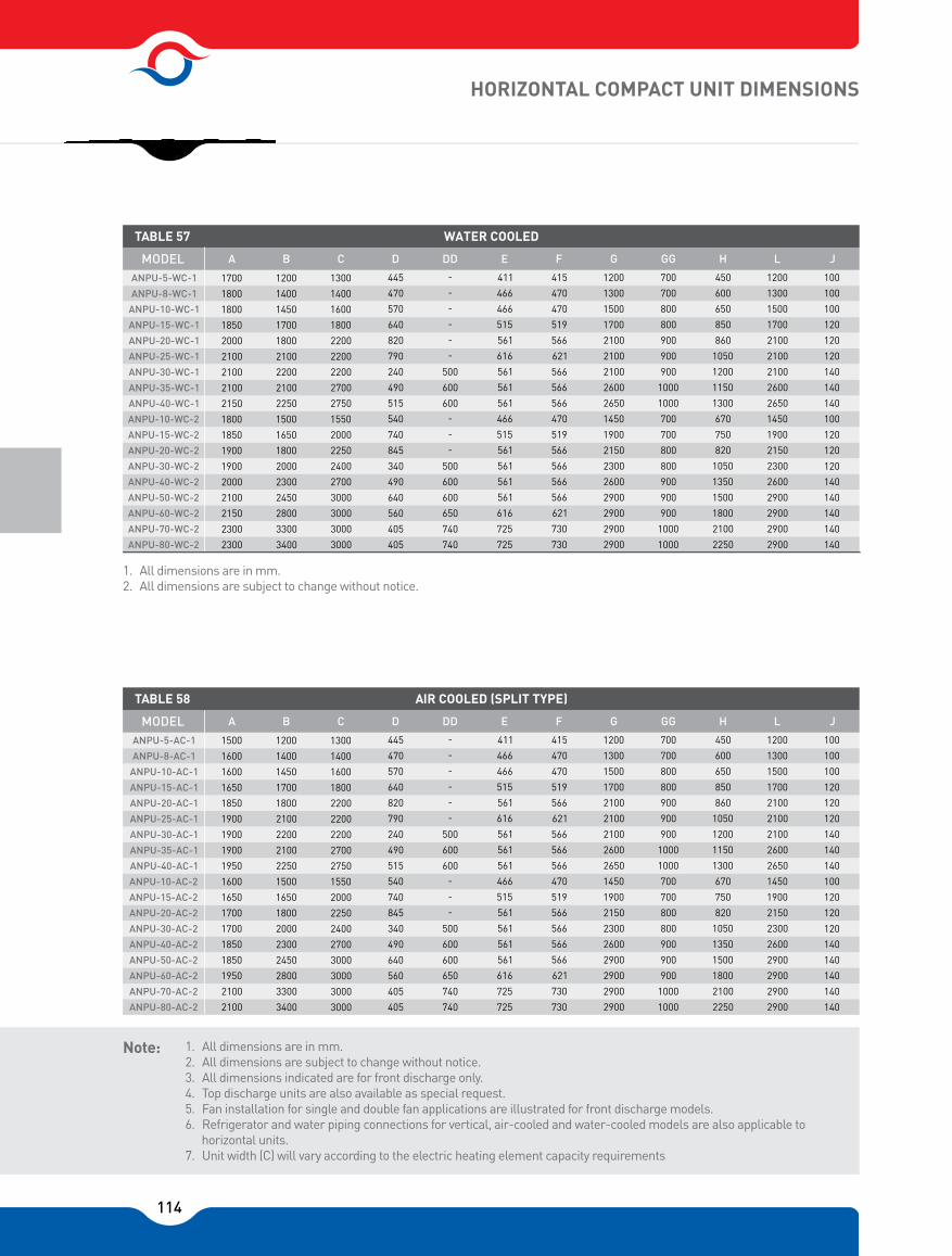
114
1. All dimensions are in mm.2. All dimensions are subject to change without notice.
1. All dimensions are in mm.2. All dimensions are subject to change without notice.3. All dimensions indicated are for front discharge only.4. Top discharge units are also available as special request.5. Fan installation for single and double fan applications are illustrated for front discharge models.6. Refrigerator and water piping connections for vertical, air-cooled and water-cooled models are also applicable to
horizontal units.7. Unit width (C) will vary according to the electric heating element capacity requirements
Note:
HORIZONTAL COMPACT UNIT DIMENSIONS
1500
1600
1600
1650
1850
1900
1900
1900
1950
1600
1650
1700
1700
1850
1850
1950
2100
2100
1200
1400
1450
1700
1800
2100
2200
2100
2250
1500
1650
1800
2000
2300
2450
2800
3300
3400
1300
1400
1600
1800
2200
2200
2200
2700
2750
1550
2000
2250
2400
2700
3000
3000
3000
3000
100
100
100
120
120
120
140
140
140
100
120
120
140
140
140
140
140
A B C D DD E F G GG H L J
1200
1300
1500
1700
2100
2100
2100
2600
2650
1450
1900
2150
2300
2600
2900
2900
2900
2900
450
600
650
850
860
1050
1200
1150
1300
670
750
820
1050
1350
1500
1800
2100
2250
700
700
800
800
900
900
900
1000
1000
700
700
800
800
900
900
900
1000
1000
1200
1300
1500
1700
2100
2100
2100
2600
2650
1450
1900
2150
2300
2600
2900
2900
2900
2900
415
470
470
519
566
621
566
566
566
470
519
566
566
566
566
621
730
730
411
466
466
515
561
616
561
561
561
466
515
561
561
561
561
616
725
725
-
-
-
-
-
-
500
600
600-
-
-
500
600
600
650
740
740
445
470
570
640
820
790
240
490
515
540
740
845
340
490
640
560
405
405
MODEL
TABLE 58
ANPU-5-AC-1
ANPU-8-AC-1
ANPU-10-AC-1
ANPU-15-AC-1
ANPU-20-AC-1
ANPU-25-AC-1
ANPU-30-AC-1
ANPU-35-AC-1
ANPU-40-AC-1
ANPU-10-AC-2
ANPU-15-AC-2
ANPU-20-AC-2
ANPU-30-AC-2
ANPU-40-AC-2
ANPU-50-AC-2
ANPU-60-AC-2
ANPU-70-AC-2
ANPU-80-AC-2
AIR COOLED (SPLIT TYPE)
120
1300
1400
1600
1800
2200
2200
2200
2700
2750
1550
2000
2250
2400
2700
3000
3000
3000
3000
1200
1400
1450
1700
1800
2100
2200
2100
2250
1500
1650
1800
2000
2300
2450
2800
3300
3400
1700
1800
1800
1850
2000
2100
2100
2100
2150
1800
1850
1900
1900
2000
2100
2150
2300
2300
100
100
100
120
120
120
140
140
140
100
120
120
140
140
140
140
140
A B C D DD E F G GG H L J
1200
1300
1500
1700
2100
2100
2100
2600
2650
1450
1900
2150
2300
2600
2900
2900
2900
2900
450
600
650
850
860
1050
1200
1150
1300
670
750
820
1050
1350
1500
1800
2100
2250
700
700
800
800
900
900
900
1000
1000
700
700
800
800
900
900
900
1000
1000
1200
1300
1500
1700
2100
2100
2100
2600
2650
1450
1900
2150
2300
2600
2900
2900
2900
2900
415
470
470
519
566
621
566
566
566
470
519
566
566
566
566
621
730
730
411
466
466
515
561
616
561
561
561
466
515
561
561
561
561
616
725
725
-
-
-
-
-
-
500
600
600-
-
-
500
600
600
650
740
740
445
470
570
640
820
790
240
490
515
540
740
845
340
490
640
560
405
405
MODEL
TABLE 57
ANPU-5-WC-1
ANPU-8-WC-1
ANPU-10-WC-1
ANPU-15-WC-1
ANPU-20-WC-1
ANPU-25-WC-1
ANPU-30-WC-1
ANPU-35-WC-1
ANPU-40-WC-1
ANPU-10-WC-2
ANPU-15-WC-2
ANPU-20-WC-2
ANPU-30-WC-2
ANPU-40-WC-2
ANPU-50-WC-2
ANPU-60-WC-2
ANPU-70-WC-2
ANPU-80-WC-2
WATER COOLED
120

115
FIGURE 7. SINGLE FAN TYPE
FIGURE 8. DOUBLE FAN TYPE
HORIZONTAL COMPACT UNIT DIMENSIONS
HOT WTER INLET
HOT WTER
OUTLET
FAN
SECTION
COMP.
SECTION
ELEC. CONTROLPANEL
B
GG
AG
C
G
L
H
EDD
E D
AIR FLOW
SERVICE AREA
HOT WTER INLET
HOT WTER
OUTLET
FAN
SECTION
COMP.
SECTION
ELEC. CONTROLPANEL
B
GG
AG
C
G
L
H
ED

116
1. All dimensions are in mm.2. All dimensions are subject to change without notice.
1. All dimensions are in mm.2. All dimensions are subject to change without notice.3. All dimensions indicated are for front discharge only.4. Top discharge units are also available as special request.5. Fan installation for single and double fan applications are illustrated for front discharge models.6. Refrigerator and water piping connections for vertical, air-cooled and water-cooled models are also applicable to
horizontal units.7. Unit width (C) will vary according to the electric heating element capacity requirements
Note:
HORIZONTAL UNIT DIMENSIONS
TABLE 59
700
800
800
1000
1000
1200
1350
1300
1400
900
950
1000
1200
1500
1650
1950
2300
2400
2650
2750
2750
2800
3000
3000
3000
3100
3100
2750
2800
2850
2850
3000
3000
3100
3250
3250
1300
1400
1600
1800
2200
2200
2200
2700
2750
1550
2000
2250
2400
2700
3000
3000
3000
3000
100
100
100
120
120
120
140
140
140
100
120
120
140
140
140
140
140
A B C D DD E F G GG J
700
700
800
800
900
900
900
1000
1000
700
700
800
800
900
900
900
1000
1000
1200
1300
1500
1700
2100
2100
2100
2600
2650
1450
1900
2150
2300
2600
2900
2900
2900
2900
415
470
470
519
566
621
566
566
566
470
519
566
566
566
566
621
730
730
411
466
466
515
561
616
561
561
561
466
515
561
561
561
561
616
725
725
-
-
-
-
-
-
500
600
600-
-
-
500
600
600
650
740
740
445
470
570
640
820
790
240
490
515
540
740
845
340
490
640
560
405
405
MODEL ANPU-5-WH-1
ANPU-8-WH-1
ANPU-10-WH-1
ANPU-15-WH-1
ANPU-20-WH-1
ANPU-25-WH-1
ANPU-30-WH-1
ANPU-35-WH-1
ANPU-40-WH-1
ANPU-10-WH-2
ANPU-15-WH-2
ANPU-20-WH-2
ANPU-30-WH-2
ANPU-40-WH-2
ANPU-50-WH-2
ANPU-60-WH-2
ANPU-70-WH-2
ANPU-80-WH-2
WATER COOLED
120
700
800
800
1000
1000
1200
1350
1300
1400
900
950
1000
1200
1500
1650
1950
2300
2400
2450
2550
2550
2600
2800
2850
2850
2850
2900
2550
2600
2650
2650
2800
2800
2900
3050
3050
1300
1400
1600
1800
2200
2200
2200
2700
2750
1550
2000
2250
2400
2700
3000
3000
3000
3000
100
100
100
120
120
120
140
140
140
100
120
120
140
140
140
140
140
A B C D DD E F G GG J
700
700
800
800
900
900
900
1000
1000
700
700
800
800
900
900
900
1000
1000
1200
1300
1500
1700
2100
2100
2100
2600
2650
1450
1900
2150
2300
2600
2900
2900
2900
2900
415
470
470
519
566
621
566
566
566
470
519
566
566
566
566
621
730
730
411
466
466
515
561
616
561
561
561
466
515
561
561
561
561
616
725
725
-
-
-
-
-
-
500
600
600-
-
-
500
600
600
650
740
740
445
470
570
640
820
790
240
490
515
540
740
845
340
490
640
560
405
405
TABLE 60
ANPU-5-AH-1
ANPU-8-AH-1
ANPU-10-AH-1
ANPU-15-AH-1
ANPU-20-AH-1
ANPU-25-AH-1
ANPU-30-AH-1
ANPU-35-AH-1
ANPU-40-AH-1
ANPU-10-AH-2
ANPU-15-AH-2
ANPU-20-AH-2
ANPU-30-AH-2
ANPU-40-AH-2
ANPU-50-AH-2
ANPU-60-AH-2
ANPU-70-AH-2
ANPU-80-AH-2
MODEL
AIR COOLED (SPLIT TYPE)
120

117
G
C
G
A
GG
B
ED
ELEC. CONTROLPANEL
HOT WTER INLET
HOT WTER
OUTLET
FAN & COIL
SECTION
FILTER
SECTION
COMP.
SECTION
F J
FIGURE 9. SINGLE FAN TYPE
FIGURE 10. DOUBLE FAN TYPE
HORIZONTAL UNIT DIMENSIONS
AIR FLOW
SERVICE AREA
G
C
G
A
GG
EDD
DE
B
ELEC. CONTROLPANEL
FILTER
SECTION
COMP.
SECTION
HOT WTER INLET
HOT WTER
OUTLET
FAN & COIL
SECTION
F
J

118
1. Compressor circuit breakers are current sensitive and temperature compensated to ensure compressor cutoff if current draw becomes excessive. Breakers must be reset manually.
2. Internal protection with automatic reset de-energizes the control circuit if extreme compressor motor temperature should occur from excessive return gas temperature or motor overloading.
3. High and low pressure controls, automatically shut off compressor(s) if refrigerant pressure exceed switch settings. This action protects compressor against loss of charge or damaged caused by excessive pressures.
4. All data are based on 125 °F condensing, 45 °F evaporating & 95 °F ambient air temperature.5. 5- All compressors are 380/420 Volts-3 phase-50 cycles.
Note:
1. All dimensions are in mm.2. All dimensions are subject to change without notice.3. All dimensions indicated are for front discharge only.4. Top discharge units are also available as special request.5. Fan installation for single and double fan applications are illustrated for front discharge models.6. Refrigerator and water piping connections for vertical, air-cooled and water-cooled models are also applicable to
horizontal units.7. Unit width (C) will vary according to the electric heating element capacity requirements
Note:
PACKAGED UNIT (WITH MIXING BOX) DIMENSIONS
TABLE 62
12.625.429.747.551.055.367.281.5
105.727.142.660.274.2
100.9137.4148.0176.6195.0
CONDENSER FAN MOTOR
NOxHP FLA
5.911.914.422.225.328.234.841.455.212.920.829.936.749.868.376.389.5
104.4
3.27.77.7
15.415.412.816.016.030.87.77.7
15.412.830.846.246.246.246.2
1.744
7.58.88.8
12.212.216.5
47.58.8
12.216.523.823.823.832
0.75224
5.55.57.57.51024
5.57.51015151520
7.713.718.024.626.833.739.053.358.415.427.436.049.253.667.478.0
106.6116.8
4.27.49.9
13.315.219.623.630.235.88.4
14.819.826.630.439.247.260.471.6
COMPRESSOR EVAPORATOR FAN MOTOR TOTAL MODEL
INPUT (KW) HP FLA POWER (KW) AMPS. AMPS. ANPU-5-AM-1ANPU-8-AM-1
ANPU-10-AM-1ANPU-15-AM-1ANPU-20-AM-1ANPU-25-AM-1ANPU-30-AM-1ANPU-35-AM-1ANPU-40-AM-1ANPU-10-AM-2ANPU-15-AM-2ANPU-20-AM-2ANPU-30-AM-2ANPU-40-AM-2ANPU-50-AM-2ANPU-60-AM-2ANPU-70-AM-2ANPU-80-AM-2
AIR COOLED ROOF TOP PACKAGED UNITS (WITH MIXING BOX) ELECTRICAL DATA
1x1.51x4.01x4.02x4.02x4.04x1.55x1.55x1.54x4.01x4.01x4.02x4.04x1.54x4.06x4.06x4.06x4.06x4.0
1100
1200
1400
1600
2000
2000
2000
2500
2550
1350
1800
2050
2200
2500
2800
2800
2800
2800
410
410
410
410
410
410
410
410
410
410
410
410
410
410
410
410
410
410
1250
1350
1350
1550
1550
1750
1900
1900
2000
1350
1450
1550
1750
2100
2200
2500
2800
2950
3850
3800
3850
4500
4700
5100
5300
5350
5600
3850
4000
4700
5100
5500
6600
6700
6800
7000
100
100
100
120
120
120
140
140
140
100
120
120
120
140
140
140
140
140
A B C D DD E F G GG K L M
700
700
800
800
900
900
900
1000
1000
700
700
800
800
900
900
900
1000
1000
1200
1300
1500
1700
2100
2100
2100
2600
2650
1450
1900
2150
2300
2600
2900
2900
2900
2900
415
470
470
519
566
621
566
566
566
470
519
566
566
566
566
621
730
730
411
466
466
515
561
616
561
561
561
466
515
561
561
561
561
616
725
725
-
-
-
-
-
-
500
600
600-
-
-
500
600
600
650
740
740
445
470
570
640
820
790
240
490
515
540
740
845
340
490
640
560
405
405
1300
1400
1600
1800
2200
2200
2200
2700
2750
1550
2000
2250
2400
2700
3000
3000
3000
3000
MODEL
TABLE 61
J
600
650
650
700
800
800
800
800
800
650
700
800
800
800
800
800
1000
1000
ANPU-5-AM-1
ANPU-8-AM-1
ANPU-10-AM-1
ANPU-15-AM-1
ANPU-20-AM-1
ANPU-25-AM-1
ANPU-30-AM-1
ANPU-35-AM-1
ANPU-40-AM-1
ANPU-10-AM-2
ANPU-15-AM-2
ANPU-20-AM-2
ANPU-30-AM-2
ANPU-40-AM-2
ANPU-50-AM-2
ANPU-60-AM-2
ANPU-70-AM-2
ANPU-80-AM-2
AIR COOLED ROOF TOP PACKAGED UNIT (WITH MIXING BOX)
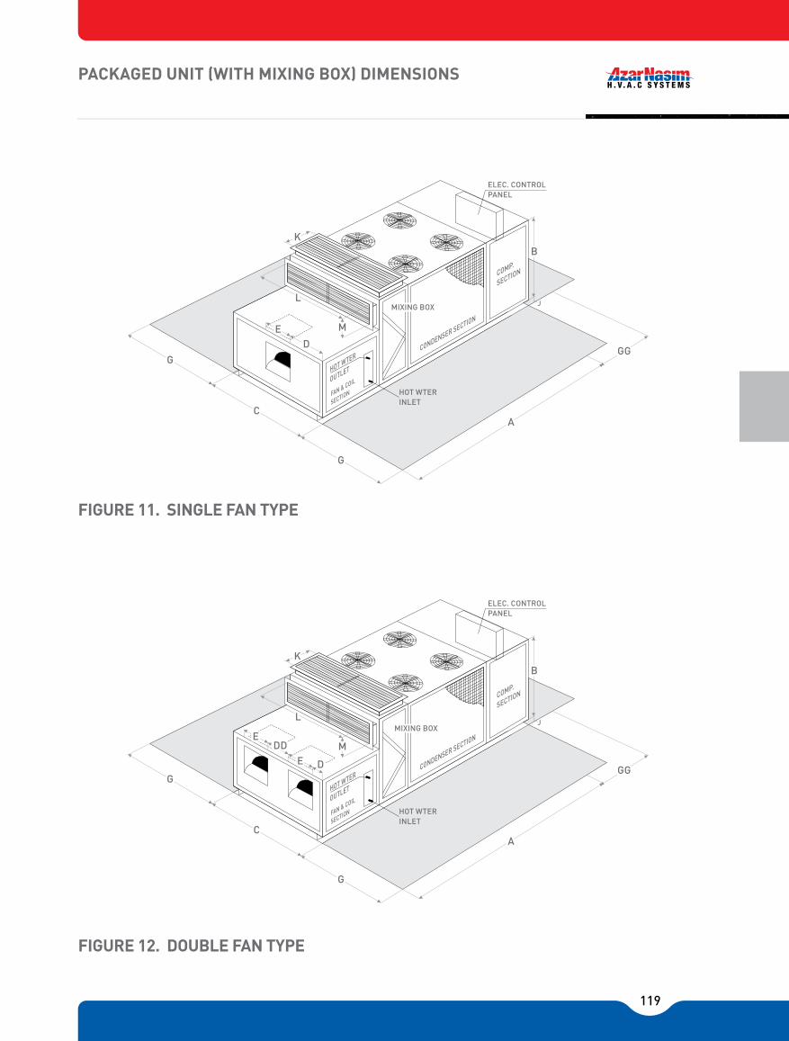
119
FIGURE 11. SINGLE FAN TYPE
FIGURE 12. DOUBLE FAN TYPE
PACKAGED UNIT (WITH MIXING BOX) DIMENSIONS
K
MIXING BOX
G
CA
GG
B
ED CONDENSER SECTION
G
ELEC. CONTROLPANEL
COMP.
SECTION
HOT WTER INLET
HOT WTER
OUTLET
L
M
FAN & COIL
SECTION
J
K
G
CA
GG
B
G
MIXING BOX
DD
COMP.
SECTION
ELEC. CONTROLPANEL
HOT WTER INLET
HOT WTER
OUTLET
FAN & COIL
SECTION
E
E
D CONDENSER SECTION
JL
M

120
*All pipe size at standard condition (CT =125 °F, FV = 500 FPM, EWB = 67 °F)** Leq = Equivalent length of pipe from package to condenser ft (meter)
*Leq = Equivalent length (feet)D = Interrnal diameter of pipe (feet)
� Minimum calculated pressure differential (psi) across the valve to fully lift the disc.
1. Refrigerant piping design must accommodate the flow of both refrigerant and oil. Proper return of oil to the crankcase is accomplished by ensuring a minimum refrigerant velocity not less than 500 fpm in horizontal lines and not less than 1500 fpm in vertical refrigerant risers. Horizontal refrigerant lines must be pitched in the direction of refrigerant flow.
2. Copper tubing installed in remote air cooled condenser systems should be entirely free of dirt, scale, and oxides. The liquid line from the condenser should be maintained dry.
3. Current practice limits the maximum pressure drop in liquid lines corresponding to a change of saturated temperature ΔTsuc = 1 °F as 3.05 psi at a condensing temperature of 105 °F.
Remote Air Cooled Condenser Notes:
PACKAGED UNIT PIPING
5/8"
3/4"
3/4"
7/8"
7/8"
1/8"
1/8"
1/8"
1 3/8"
2x5/8"
2x3/4"
2x3/4"
2x7/8"
2x7/8"
2x11/8"
2x11/8"
2x11/8"
2x13/8"
7/8"
11/8"
11/8"
13/8"
13/8"
2x7/8"
2x11/8"
2x11/8"
2x13/8"
2x11/3"
2x15/8"
2x15/8"
2x15/8"
2x21/8"
1/2"
5/8"
5/8"
3/4"
3/4"
7/8"
1 1/8"
2x1/2"
2x5/8"
2x5/8"
2x3/4"
2x3/4"
2x7/8"
2x11/8"
2x11/8"
2x11/8"
5/8"
3/4"
3/4"
7/8"
7/8"
2x3/4"
2x3/4"
2x7/8"
2x7/8"
2x7/8"
2x11/8"
2x11/8"
2x11/8"
2x11/8"
7/8"
11/8"
11/8"
13/8"
13/8"
2x7/8"
2x11/8"
2x11/8"
2x13/8"
2x13/8"
2x15/8"
2x15/8"
2x15/8"
2x21/8"
7/8"
11/8"
11/8"
13/8"
13/8"
1 3/8"
2 1/8"
2x7/8"
2x11/8"
2x11/8"
2x13/8"
2x13/8"
2x13/8"
2x15/8"
2x15/8"
2x21/8"
1/2"
5/8"
5/8"
3/4"
3/4"
7/8"
7/8"
7/8"
1/8"2
2x1/2"
2x5/8"
2x5/8"
2x3/4"
2x3/4"
2x7/8"
2x7/8"
2x7/8"
2x11/8"
7/8"
11/8"
11/8"
11/8"
11/8"
13/8"
13/8"
13/8"
15/8" 1
2x7/8"
2x11/8"
2x11/8"
2x11/8"
2x11/8"
2x11/8"
2x13/8"
2x13/8"
2x15/8"
1/2"
1/2"
5/8"
5/8"
5/8"
3/4"
3/4"
7/8"
7/8"
2x1/2"
2x1/2"
2x5/8"
2x5/8"
2x5/8"
2x3/4"
2x3/4"
2x7/8"
2x7/8"
3/4"
7/8"
7/8"
11/8"
11/8"
11/8"
11/8"
13/8"
13/8"
2x3/4"
2x7/8"
2x7/8"
2x11/8"
2x11/8"
2x11/8"
2x11/8"
2x13/8"
2x13/8"
Leq** 32 ft (10m) 64 ft (20m) 96 ft (30m) 120 ft (40m) 160 ft (50m)
Model Discharge liquid
TABLE 63
Discharge Discharge Discharge Discharge liquid liquid liquid liquid
ANPU-5-A-1
ANPU-8-A-1
ANPU-10-A-1
ANPU-15-A-1
ANPU-20-A-1
ANPU-25-A-1
ANPU-30-A-1
ANPU-35-A-1
ANPU-40-A-1
ANPU-10-A-2
ANPU-15-A-2
ANPU-20-A-2
ANPU-30-A-2
ANPU-40-A-2
ANPU-50-A-2
ANPU-60-A-2
ANPU-70-A-2
ANPU-80-A-2
PIPE SIZING* FOR SPLIT TYPE AIR COOLED CONDENSER
1 15/8"
1 5/8" 1 1/8"
1 1/8" 1 1/8"
1 15/8"
1 5/8"
1 5/8" 1 1/8"
1 1/8"
1 1/8"
1 1/8"
1 5/8"
1 5/8"
1 5/8"
1 1/8"
301620
502657
2060
5013550
175200150
DESCRIPTION OF PRODUCT EQUIVALENT LENGTH
IN PIPE DIAMETERS (L/D)
90 Degree standard elbow45 Degree standard elbow90 Degree long radius elbow
90 Degree street elbow45 Degree street elbowSquare corner elbow
Standard tee (with ow throgh run)Standard tee (with ow throgh branch)
Close pattern return bendConventional swingClearway swingGlobe lift or stop; Y-patternAngle lift or stopin line ball
0.5 T ... Fully open0.5 T ... Fully open0.2 T ... Fully open0.2 T ... Fully open
2.5 vertical and 0.25 horizontal T ... Fully open
TABLE 64
Fittings
Check Valves
EQUIVALENT LENGTH IN PIPE DIAMETERS (Leq / D*) OF VARIOS AND FITTINGS
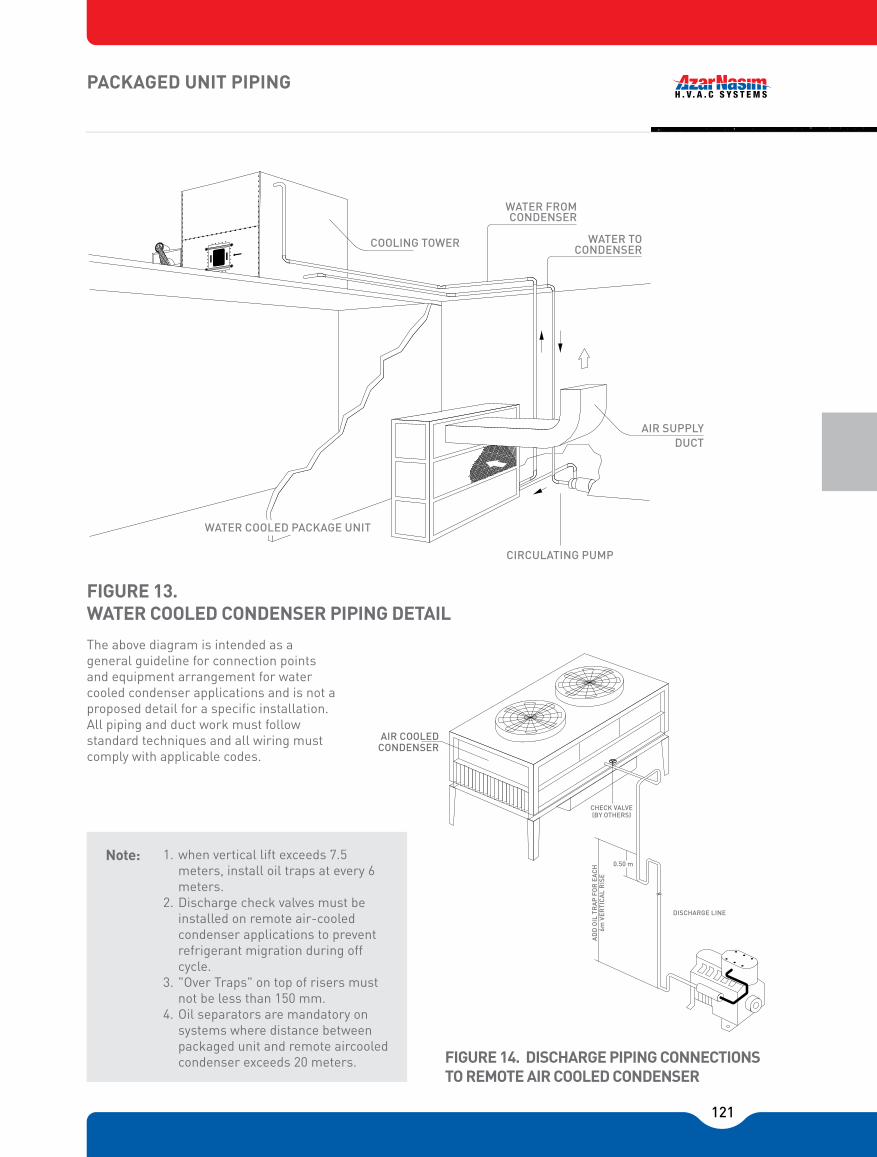
121
FIGURE 13. WATER COOLED CONDENSER PIPING DETAIL
FIGURE 14. DISCHARGE PIPING CONNECTIONS TO REMOTE AIR COOLED CONDENSER
The above diagram is intended as a general guideline for connection points and equipment arrangement for water cooled condenser applications and is not a proposed detail for a specific installation. All piping and duct work must follow standard techniques and all wiring must comply with applicable codes.
1. when vertical lift exceeds 7.5 meters, install oil traps at every 6 meters.
2. Discharge check valves must be installed on remote air-cooled condenser applications to prevent refrigerant migration during off cycle.
3. "Over Traps" on top of risers must not be less than 150 mm.
4. Oil separators are mandatory on systems where distance between packaged unit and remote aircooled condenser exceeds 20 meters.
Note:
PACKAGED UNIT PIPING
COOLING TOWER
WATER FROM CONDENSER
WATER TO CONDENSER
AIR SUPPLY DUCT
CIRCULATING PUMP
WATER COOLED PACKAGE UNIT
AIR COOLEDCONDENSER
CHECK VALVE (BY OTHERS)
AD
D O
IL T
RA
P F
OR
EA
CH
6m V
ERTI
CA
L R
ISE
0.50 m
DISCHARGE LINE
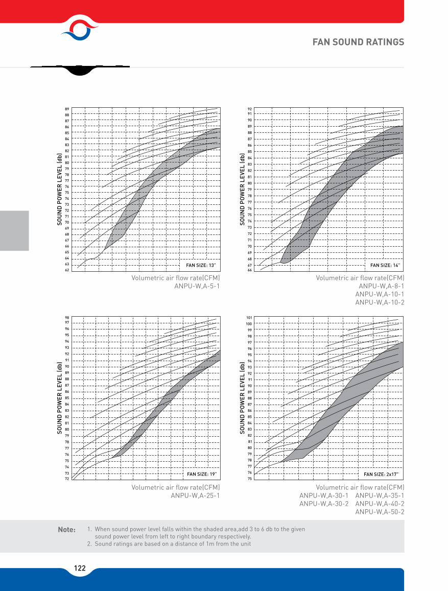
122
FAN SOUND RATINGS
Volumetric air flow rate(CFM)ANPU-W,A-5-1
Volumetric air flow rate(CFM)ANPU-W,A-25-1
Volumetric air flow rate(CFM)ANPU-W,A-8-1
ANPU-W,A-10-1ANPU-W,A-10-2
Volumetric air flow rate(CFM)ANPU-W,A-30-1 ANPU-W,A-35-1ANPU-W,A-30-2 ANPU-W,A-40-2
ANPU-W,A-50-2
89
88
87
86
85
84
83
82
81
80
79
78
77
76
75
74
73
72
71
70
69
68
67
SOU
ND
PO
WER
LEV
EL (d
b)
66
65
64
63
62FAN SIZE� 13
SOU
ND
PO
WER
LEV
EL (d
b)
9291
90
89
88
87
86
85
84
83
82
81
80
79
78
77
76
75
74
73
72
71
70
68
6766
69
FAN SIZE� 14
93
92
91
90
89
88
87
86
85
84
83
82
81
80
79
78
77
76
75
74
7372
9897
96
95
94
SOU
ND
PO
WER
LEV
EL (d
b)
FAN SIZE� 19
SOU
ND
PO
WER
LEV
EL (d
b) 93
92
91
90
89
88
87
86
85
84
83
82
81
80
79
78
77
76
75
98
97
96
95
94
101
100
99
FAN SIZE� 217
1. When sound power level falls within the shaded area,add 3 to 6 db to the given sound power level from left to right boundary respectively.
2. Sound ratings are based on a distance of 1m from the unit
Note:

123
FAN SOUND RATINGS
Volumetric air flow rate(CFM)ANPU-W,A-15-1ANPU-W,A-15-2
Volumetric air flow rate(CFM)ANPU-W,A-60-2
Volumetric air flow rate(CFM)ANPU-W,A-20-1ANPU-W,A-20-2
Volumetric air flow rate(CFM)ANPU-W,A-70-2ANPU-W,A-80-2
FAN SIZE� 16
9392
91
90
89
88
87
86
85
84
83
82
81
80
79
78
77
76
75
74
73
72
71
70
69
6867
SOU
ND
PO
WER
LEV
EL (d
b)
FAN SIZE� 17
93
92
91
90
89
88
87
86
85
84
83
82
81
80
79
78
77
76
75
74
73
72
71
7069
9594
SOU
ND
PO
WER
LEV
EL (d
b)
FAN SIZE� 219
93
92
91
90
89
88
87
86
85
84
83
82
81
80
79
78
77
76
75
74
7372
9897
96
95
94
SOU
ND
PO
WER
LEV
EL (d
b)
FAN SIZE� 222
SOU
ND
PO
WER
LEV
EL (d
b) 93
92
91
90
89
88
87
86
85
84
83
82
81
80
79
78
77
76
75
98
97
96
95
94
101
100
99
1. When sound power level falls within the shaded area, add 3 to 6 db to the given2. sound power level from left to right boundary respectively.3. Sound ratings are based on a distance of 1m from the unit
Note:
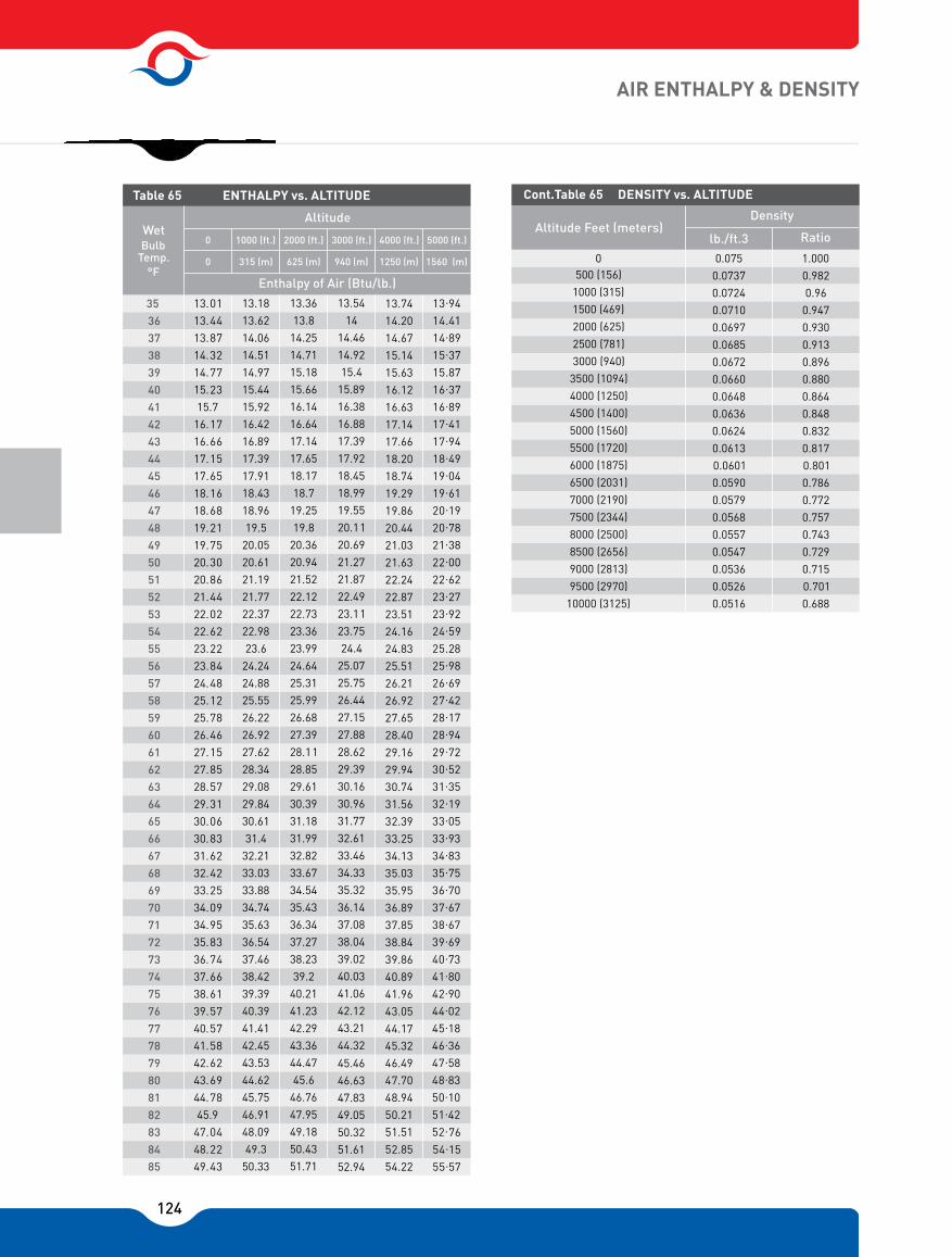
124
AIR ENTHALPY & DENSITY
Table 65 ENTHALPY vs. ALTITUDE
WetBulb
Temp.°F
Altitude
Enthalpy of Air (Btu/lb.)
0 1000 (ft.) 2000 (ft.) 3000 (ft.) 4000 (ft.) 5000 (ft.)
315 (m)0 625 (m) 940 (m) 1250 (m) 1560 (m)
35 3637383940414243444546474849505152535455565758596061626364656667686970717273747576777879808182838485
13.0113.4413.8714.3214.7715.2315.7
16.1716.6617.1517.6518.1618.6819.2119.7520.3020.8621.4422.0222.6223.2223.8424.4825.1225.7826.4627.1527.8528.5729.3130.0630.8331.6232.4233.2534.0934.9535.8336.7437.6638.6139.5740.5741.5842.6243.6944.7845.9
47.0448.2249.43
13.1813.6214.0614.5114.9715.4415.9216.4216.8917.3917.9118.4318.9619.5
20.0520.6121.1921.7722.3722.9823.6
24.2424.8825.5526.2226.9227.6228.3429.0829.8430.6131.4
32.2133.0333.8834.7435.6336.5437.4638.4239.3940.3941.4142.4543.5344.6245.7546.9148.0949.3
50.33
13.3613.8
14.2514.7115.1815.6616.1416.6417.1417.6518.1718.7
19.2519.8
20.3620.9421.5222.1222.7323.3623.9924.6425.3125.9926.6827.3928.1128.8529.6130.3931.1831.9932.8233.6734.5435.4336.3437.2738.2339.2
40.2141.2342.2943.3644.4745.6
46.7647.9549.1850.4351.71
13.5414
14.4614.9215.4
15.8916.3816.8817.3917.9218.4518.9919.5520.1120.6921.2721.8722.4923.1123.7524.4
25.0725.7526.4427.1527.8828.6229.3930.1630.9631.7732.6133.4634.3335.3236.1437.0838.0439.0240.0341.0642.1243.2144.32
45.4646.6347.8349.0550.3251.6152.94
13.7414.2014.6715.1415.6316.1216.6317.1417.6618.2018.7419.2919.8620.4421.0321.6322.2422.8723.5124.1624.8325.5126.2126.9227.6528.4029.1629.9430.7431.5632.3933.2534.1335.0335.9536.8937.8538.8439.8640.8941.9643.0544.1745.3246.4947.7048.9450.2151.5152.8554.22
13.9414.4114.8915.3715.8716.3716.8917.4117.9418.4919.0419.6120.1920.7821.3822.0022.6223.2723.9224.5925.2825.9826.6927.4228.1728.9429.7230.5231.3532.1933.0533.9334.8335.7536.7037.6738.6739.6940.7341.8042.9044.0245.1846.3647.5848.8350.1051.4252.7654.1555.57
Cont.Table 65 DENSITY vs. ALTITUDE
Altitude Feet (meters)Density
lb./ft.3 Ratio
0.075 1.000 0.0737 0.982 0.0724 0.96 0.0710 0.947 0.0697 0.930 0.0685 0.913 0.0672 0.896 0.0660 0.880 0.0648 0.864 0.0636 0.848 0.0624 0.832 0.0613 0.817 0.0601 0.801 0.0590 0.786 0.0579 0.772 0.0568 0.757 0.0557 0.743 0.0547 0.729 0.0536 0.715 0.0526 0.701 0.0516 0.688
0 500 (156)
1000 (315) 1500 (469) 2000 (625) 2500 (781) 3000 (940)
3500 (1094) 4000 (1250) 4500 (1400) 5000 (1560) 5500 (1720) 6000 (1875) 6500 (2031) 7000 (2190) 7500 (2344) 8000 (2500) 8500 (2656) 9000 (2813) 9500 (2970)
10000 (3125)

125
ENGINEERING SPECIFICATION
Furnish and install AzarNasim Packaged Air Conditioning unit(s) utilizing reciprocating industrial-duty semi-hermetic compressor(s). Unit shall supply air through ductwork based on the schedule of capacities as shown on the contract drawings and the following specifications. The unit shall consist of serviceable semi-hermetic compressors(s), coil section complete with directexpasion coil, condensate drain pan, liquid receiver, filter rack, fan section, factory wiring, and controls. A holding charge of (R-22) shall be furnished. All units shall be rated to ARI Standards 310 and 360.
CASINGSThe enclosure shall be of heavy gage galvanized steel sheet panels, cleaned and finished with baked enamel. The inside of the panels shall be completely insulated with 19 mm rock wool panel with aluminum foil cover. Panels shall be removable for access to the components.
FAN SECTIONDouble-inlet centrifugal fan wheel with forward curved blades shall be designed for continuous operation at maximum fan speed. Fan wheel shall be constructed of galvanized steel sheets and shall be statically and dynamically balanced for smooth running and quiet operation. Fan shall be belt driven and mounted on a solid steel shaft with greasable ball bearings. Fan shaft shall be phosphatized.
FAN MOTORThe electric motor shall be totally enclosed, fan cooled motor selected to match the fan bhp. The motor shall operate at 1450 rpm suitable for 380 volts, 3 phase and 50 cycle operation. Fan motor shall have V-Belt driven, with oversized V-Belt for long lift. The motor base shall be adjustable for belt tension control. The driven shall incorporate multiroove sheave and pulley.
COOLING COILThe cooling coil shall be multi-row, direct expansion type, designed and tested in
accordance with ANSI/ASHRAE 15 Safety Code for Mechanical Refrigeration. Primary surface is 5/8" (16mm) O.D. seamless copper tube with all joints brazed. Secondary surface shall be aluminum/copper fin plates in spacings of 8/14 fins per inch. A filter frame designed to accept standard 2" cleanable aluminum mesh filter shall be installed upstream of the DX-Cooling Coil.
HEATING COILHot water heating coils shall be factory tested for leakage at 350 psig air pressure with the coil submerged in water. Electric heating coil shall be constructed of stainless steel heating elements and interlocked with the supply fan.
CONDENSATE PANCondensate pan shall be of heavy gage galvanized steel sheet with a coating of bitumen. The pan shall be equipped with drain connection.
CONDENSER (Water Cooled Only) The condenser shall be shell and tube type with removable steel heads. The tubes shall be integrally finned copper tubes. The tubes shall be designed for a working pressure of 250 psig and tested in accordance with ASME Section VIII, Div. 1 code requirements. Each condenser shall be constructed to provide subcooling of the liquid refrigerant. The condenser shall be equipped with a safety relief valve mounted on the shell for safe operation.
CONDENSER COIL (Air Cooled Only) Air cooled condenser coils shall be rated according to ARI 460 and constructed 5/8" O.D. seamless copper tube with secondary surface consisting of a choice of aluminum/copper fin plates in spacings of 8/14 fins per inch.
REFRIGERATION CIRCUITRefrigeration control provided by thermal expansion valve. Sight glass shall be installed upstream of the expansion valve. All models shall be equipped with back seating shutoff valve in liquid lines. Filter-drier and operating charge of R-22 shall be standard.
GENERAL

126
AIR ENTHALPY & DENSITY
RECEIVERLiquid refrigerant receiver shall be sized to hold refrigerant charge on pump down application as per ASHRAE 15 and designed, fabricated, and tested to ASME Section VIII, Div. 1 requirements.
CONTROLS AND SAFETIESAll control circuits shall be 220V-50Hz-single phase. A single/multi stage thermostat shall provide capac-ity modulation by cycling compressor(s) ON/OFF along with control of condenser fan(s). An electrical interlock for remote condenser fan shall be provided. Contactors plus overload protections shall be provided for all motors. The compressor shall be provided with the following controls: high pressure, low pressure, overtemperature, overcurrent, and short cycle in addition to oil pressure safety cut out.

127
AIR DRY TEMPERATURE °F
Research conducted over 50 years by ASHREA wasconsolidated in the 1993 edition of the ASHREAHandbook of Fundamentals. It shows that during thesummer months, the majority of the population ismost comfortable between temperatures of 74 and80°F with coincident relative humidities between 25and 60%. The center of that comfort zone - the mostcomfortable point for the majority of the population -is 78°F and 45% rh.
DE
W P
OIN
T TE
MP
ER
ATU
RE
°F
70
65
60
55
50
45
40
35
30
25
20
10
7860 65 70 75 80 85 90
HU
MID
ITY
RAT
IO L
BS.
WAT
ER V
AP
OR
PER
LB
. OF
DR
Y A
IR
WINTER SUMMER
100%
70%
60%
50%
45%
40%
30%
65° 79°
EFFE
CTIV
ETE
MP
ERAT
UR
E
15
10
5
128

129
AIR HANDLING UNIT
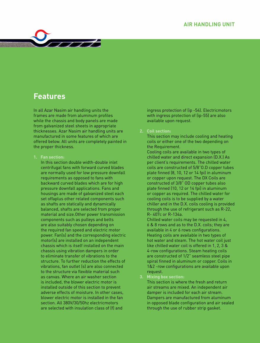
130
Features
AIR HANDLING UNIT
In all Azar Nasim air handling units the frames are made from aluminum profiles while the chassis and body panels are made from galvanized steel sheets in appropriate thicknesses. Azar Nasim air handling units are manufactured in some features of which are offered below. All units are completely painted in the proper thickness.
1. Fan section:In this section double width-double inlet centrifugal fans with forward curved blades are normally used for low pressure downfall requirements as opposed to fans with backward curved blades which are for high pressure downfall applications. Fans and housings are made of galvanized steel each set offaplus other related components such as shafts are statically and dynamically balanced, shafts are selected from proper material and size.Other power transmission components such as pulleys and belts are also suitably chosen depending on the required fan speed and electric motor power. Fan(s) and the corresponding electric motor(s) are installed on an independent chassis which is itself installed on the main chassis using vibration dampers in order to eliminate transfer of vibrations to the structure. To further reduction the effects of vibrations, fan outlet (s) are also connected to the structure via flexible material such as canvas. Where an air washer section is included, the blower electric motor is installed outside of this section to prevent adverse effects of moisture. In other cases, blower electric motor is installed in the fan section. All 380V/30/50hz electricmotors are selected with insulation class of (f) and
ingress protection of (ip -54). Electricmotors with ingress protection of (ip-55) are also available upon request.
2. Coil section:This section may include cooling and heating coils or either one of the two depending on the Requirement.Cooling coils are available in two types of chilled water and direct expansion (D.X.) As per client�s requirements. The chilled water coils are constructed of 5/8�O.D copper tubes plate finned (8, 10, 12 or 14 fpi) in aluminum or copper upon request. The DX Coils are constructed of 3/8� OD copper tubes also plate finned (10, 12 or 14 fpi) in aluminum or copper as required. The chilled water for cooling coils is to be supplied by a water chiller and in the D.X. coils cooling is provided through the use of refrigerant such as R-22, R- 407c or R-134a.Chilled water coils may be requested in 4, 6 & 8 rows and as to the D.X. coils; they are available in 4 or 6 rows configurations.Heating coils are available in two types of hot water and steam. The hot water coil just like chilled water coil is offered in 1, 2, 3 & 4-row configurations. Steam heating coils are constructed of 1/2� seamless steel pipe spiral finned in aluminum or copper. Coils in 1&2 -row configurations are available upon request.
3. Mixing box section:This section is where the fresh and return air streams are mixed. An independent air damper is included for each air stream. Dampers are manufactured from aluminum in opposed blade configuration and air sealed through the use of rubber strip gasket.

131
Damper actuators maybe easily installed when required. 2 inches Washable aluminum filter modules are arranged in (V) type configuration inside these boxes. Housing for pleated type air filters may also be considered in the mixing box.
4. Special filter section:This section may include pleated or bag filter which are installed as per customer requirements. Efficiency and class of special filters are specified by the client.
Notes:• Allowable air velocity must be over the
special filter section.• In cases where only pleated filters are
required they are easily installed in themixing box and not in the special filter section.
5. Multi - Zone Section:In some cases the air conditioning design of a building defines different zones to be air conditioned, each zone requiring its own air flow rate and air temperature. In these cases instead of using a few air handling units, a multi -zone unit is usually installed. Inthemulti-zone air handling unit, cooling and the heating coils are paralleled with each other which means that some of the air passes over the cooling coil and the remainder passes over the heating coil and at the outlet the result is a mixture of the two which has the suitable temperature for each zone. Inmulti-zone units the cooling coil area is the same size as that of a regular air handling unit while the size of the heating coil is less. For each zone two outlet dampers
are installed one which is on the cooling coil side and one that is on the heating coil side active. When outlet damper is open, the other one is close. The same amount, therefore, by adjusting the outlet dampers for each zone, the desired zone temperature is controlled. Number and the effective area of dampers for each zone are dependent on the number of zones and the air flow rate needed for that zone. These aluminum dampers are located either on top or the blank side of this section depending on the type of air handling unit is up blast or horizont al blast discharge. Multi-zone section is usually installed after the fan section and in order to have the proper air flow over the coils air diffuser is also installed. Humidifiers are also installed in this section when required.

132
Selection procedureThe first parameter to consider in the selection of an air handling unit is the required air flow rate (CFM) therefore,by having the required air flow rate, coil face area and the available nominal air flow rate for the unit, the appropriate model may be chosen.Notes: Allowable air velocity over cooling coils is less than 550FPM.In air handling units equipped with air Washers this allowable airvelocity shall be reduced further to less than 500 FPM.Considering the cooling and heating loads and the entering air conditions. The number of coil rows, pressure drops on both water and air sides and the required model of fan may be determined using the data available in the catalogue. Other components and accessories such as air mixing box, special filters, humidifier, etc. May also be selected from the ccatalogue as needed.
Chilled water Cooling, Hot water Heating Given: Required air flow rate = 10000 CFMCooling entering air condition = 80 F DB, 67 F WB Heating entering air condition = 60 F DBEntering chilled water temp. = 45 F Leaving chilled water temp. = 55 F Entering hot water temp. = 180F Leaving hot water temp. = 160 F Total cooling load = 480 MBHTotal heating load = 700 MBH Cooling & heating coil FPI = 14External static pressure drop. = 0.78 In W. G Maximum coil face velocity = 500 FPMFilter arrangement = V - typeConsidering the required airflow rateincfm and the uninominal airflow rate, model AHU-1000 is chosen. From table 5@ the given cooling capacity and the chilled water temp. A6-Rows coi l are chosen. (Cooling capacity of the unit is 498 MBH) From table 7@ the given heating capacity and the hot water temp. A2 - Rows coil are chosen. (Heating capacity of the unit is 726MBH).Note: Incases where there rquirement for number of fin per inchis not specified, a coil with the least number Of rows with 8, 10, 12 or14FPI which fulfills the requirement is chosen.
Preference is usually given to 14 FPI.• Determine the actual coil face velocity.
CFM 10000F.V. Actual = = = 500 F.P.M F.A 20
• Knowing the actual coil velocity and the coils chosen, determine the total internal air side pressure downfall for the unit. From the table
P.D. Cooling coil = P. D. (Table 17) x C.F. (T able 10A) = 0.85 * 1.45 = 1.19 In W.GP.D. Heating coil = P. D. (Table 17) x C.F. (Table10A) = 0.22 * 1.45 = 0.32 In W.GP.D. Filter = 0.099 In W.GP.D. Accessories= 0.05 + 0.06 = 0.11 In W.G (damper & mixing box from table 18).Total internal pressure drop (T. I.P .D)Tot al external pressure drop (T.E.P .D)T.I.P .D = P.D. Cooling coil + P.D. Heating c o i l + P.D. Filter + P.D. aaccessoriesT.I.P .D = 1.19 + 0.32 + 0.099 + 0.11 = 1.719 In W.GTotal static pressure (T.S.P)= T.I.P .D + T.E.P .D = 1.719 + 0.78 = 2.5 In W.GTherefore, by using table 1 and performing interpolation the required fan size is determined as 22” at the speed of 703 RPM and electric motor power requi rement of 10 HP.• Determine the water side P.D. (Cooling Coil):
Total heating load 498000 Water flow rate (GPM) = = = 500×ΔT 500×10
> = 99.6 GM
Water velocity inside the tubes = Water Flow Rate (GPM) > = 1.235 = No. of coils × No. of circuits (Table 19) 99.6 > = × 1.235 = 4.39 Ft / Sec 1 × 28 • From table 21consideringthe 6 rows cooling
coil, the water v e l o c i t y of 4.39 Ft/Sec the pressure drop is given as 10.52 Ft. W.G.-Determine the water side pressure drop (Heating Coil):
Total heating load 726000 Water flow rate (GPM) = = = 500×ΔT 500×10
> = 72.6 GMWater velocity inside the tubes =
Water Flow Rate (GPM) > = 1.235 = No. of coils × No. of circuits (Table 19) 72.6 > = × 1.235 = 3.2 Ft / Sec 1 × 28

133
From Table 21 considering the 2 row heating coil, the water velocity of 3.2 Ft /Sec, the pressure drop is given 2.62 Ft w.g and a.The average water temp, of 170 F correction factor is0.77 theref ore, the actual P.D. is 2.02 Ft W.G.
D.X. COOLING, STEAM HEATING Given: Required air flow rate = 9500 CFMCooling entering air condition = 80˚F DB, 67˚F WBHeating entering air condition = 60˚F DBTotal cooling load = 450 MBHTotal heating load = 950 MBHCooling coil FPI = 14Heating coil FPI = 8Evaporating temperature = 45 ˚FSteam pressure = 5 psigExternal static pressure downfall. = 0.5 in. WGMaximum coil face velocity = 500 FPMFilter arrangement = flat type
Considering the required air flow rate in cfm and the unit available nominal air flow rate, air handling unit model AHU- 1000 is chosen.
• Fromtable 9@ the givenwilling capacity and the evap. temp. a 6-rows chosen (willingcapacity of the units is 471 MBH)
• Fromtable 8@the given heating capacity and the steampressure of 5psig, a 2-rows heating coil is chosen.(Heating capacity of the unit is 980MBH)
Determine the actual coil face velocity.
CFM 9500 Actual F.V. = = = 475 F.P.M F.A 20
Referring to the correction factors in table12, the cooling and the heating capacity correction factors are given as 0.97 And 0.98 Respectively.
• Corrected cooling capacity = 471x0.97= 456.8 MBH
• Corrected heating capacity= 980x0.98= 960.4MBH
Therefore, the chosen cooling and heating coils fulfill the requirements.
• Knowing the actual coil face velocity and the coils chosen, determine the total internal air side pressure drop for the unit.
P.D. DX coil = P.D. (Table 17) x C.F. (Table 17A) => > 0.79 x 1.45 = 1.15 in W.G
P.D. Heating coil = P.D. (Table 17) x C.F. >> (Table 10A) = 0.21 x 1 = 0.21 in W.GP.D. Filter = 0.09 in W.G (table 9)
P.D. Accessories = 0.05 in W.G (Table 18) >> Total internal pressure d downfall. (T. I.P .D)>> Tot al external pressure downfall (T.E.P.D)
T.I.P.D = P.D. DX Coil + P.D. Heating coil+ >> P. D. Filter accessories = >> 1.15 + 0.2 + 0.09 + 0.05 = 1.5 in W.G
Total static pressure(T .S.P) = T.I.P .D + T.E.P .D> >=1.5 +0.5 = 2 in W.G
Therefore, by using table18 and performing interpolation the required fan size is determined as22” At the speed of 629 RPM and electric motor power requirement of 7.5 HP.

134
Fan Performance
AHU 250 1 × 14'' 5
AHU 350 1 × 16'' 7
AHU 500 1 × 17'' 10
AHU 700 1 × 19'' 15
AHU 1000 1 × 22'' 20
AHU 1200 1 × 22'' 25
AHU 1500 1 × 26'' 30
AHU 1700 1 × 26'' 35
515
536
561
583
609
662
717
478
501
526
553
580
454
478
535
541
414
436
353
373
395
417
318
339
358
380
386
326
349
373
294
314
335
352
0.5
0.5
0.5
0.75
0.75
1
1.5
0.5
0.75
1
1
1.5
1
1.5
1.5
1.5
1.5
1.5
2
3
3
4
3
3
4
5.5
5.5
3
4
5.5
4
5.5
5.5
7.5
400
450
500
550
600
700
800
400
450
500
550
700
800
600
400
450
500
550
600
700
800
400
450
500
550
600
700
800
400
450
500
550
600
700
800
400
450
500
550
600
700
800
400
450
500
550
600
700
400
450
500
550
600
700
2000
2250
2500
2750
3000
3500
4000
2800
3150
3500
3850
4900
5600
4200
4000
4500
5000
5500
6000
7000
8000
6000
6750
7500
8200
9000
10500
12000
8000
9000
10000
11000
12000
14000
16000
10000
11250
12500
13750
15000
17500
20000
12000
13500
15000
16500
18000
21000
14000
15750
17500
19250
21000
24500
614
623
639
654
677
726
780
554
570
589
613
691
746
639
515
539
566
591
621
677
474
491
512
533
557
401
418
436
457
478
525
357
373
391
428
432
474
362
382
404
427
458
327
344
363
382
413
425
0.5
0.75
0.75
0.75
1
1.5
1.5
0.75
1
1
1.5
2
3
1.5
1
1.5
1.5
2
2
3
1.5
2
3
3
4
3
3
4
4
5.5
7.5
3
4
5.5
5.5
7.5
10
4
5.5
5.5
7.5
10
4
5.5
7.5
10
10
15
702
709
714
726
742
783
837
632
637
650
668
741
794
691
571
592
610
636
665
721
778
530
542
560
580
601
646
448
459
475
493
512
554
601
394
405
422
440
459
499
542
396
413
434
454
477
524
358
372
389
405
425
466
0.75
0.75
0.75
1
1
1.5
2
1
1.5
1.5
1.5
3
3
2
1.5
1.5
2
3
3
4
5.5
2
3
3
4
4
5.5
3
4
4
5.5
5.5
7.5
15
4
4
5.5
7.5
7.5
10
15
4
5.5
7.5
7.5
10
15
5.5
7.5
7.5
10
15
15
784
793
806
842
886
708
707
711
723
786
837
742
631
641
656
682
732
757
818
543
593
605
621
642
684
729
497
502
513
528
546
585
628
443
450
483
478
496
533
574
430
444
461
481
502
547
389
400
414
431
448
486
1
1.5
1.5
1.5
2
1.5
1.5
1.5
2
3
4
2
1.5
2
3
3
4
4
5.5
3
3
3
4
4
5.5
7.5
4
4
5.5
5.5
7.5
10
15
4
5.5
5.5
7.5
10
15
15
5.5
7.5
7.5
10
10
15
5.5
7.5
10
10
15
20
865
868
872
896
933
785
777
774
780
830
878
791
692
693
702
722
723
796
848
648
645
651
664
681
722
763
545
548
551
563
577
614
655
482
484
493
500
522
554
596
464
474
488
506
526
569
422
428
439
453
470
506
998
1005
1030
908
898
892
617
955
893
803
798
798
803
818
858
914
748
750
755
757
757
791
888
627
630
638
640
641
669
705
563
555
554
560
572
600
636
536
538
542
555
571
610
489
484
490
500
512
534
Table 1
Model
Fan Size
Coil Face area sq.ft² FPM CFM
Total static pressure in inches of water
0.5� 0.75� 1� 1.25� 1.5� 2�
RPM HP RPM RPM RPM RPM RPMHP HP HP HP HP
2
3
3
3
3
4
4
4
3
3
4
4
4
5.5
5.5
4
4
5.5
5.5
5.5
7.5
10
5.5
7.5
7.5
7.5
10
15
15
7.5
7.5
10
10
15
15
20
7.5
10
10
15
15
20
10
10
15
15
15
20
3
1.5
1.5
1.5
2
3
1.5
1.5
2
2
3
4
3
2
2
3
3
3
5.5
5.5
3
3
4
4
5.5
7.5
10
4
5.5
5.5
7.5
7.5
10
15
5.5
5.5
7.5
7.5
10
15
20
5.5
7.5
7.5
10
15
15
7.5
7.5
10
15
15
20

135
Fan Performance
Note: Selections in shaded areas not recommended for cooling applications.
AHU 2000 1 × 29'' 40
400
450
500
550
16000
18000
20000
22000
600
700
24000
28000
AHU 2200 1 × 29'' 45
400
450
500
550
18000
20250
22500
24750
600
700
800
27000
31500
36000
AHU 2500 2 × 22'' 50
400
450
500
550
20000
22500
25000
27500
600
700
800
30000
35000
40000
AHU 3000 2 × 26'' 60
400
450
500
550
24000
27000
30000
33000
600
700
36000
42000
AHU 3500 2 × 29'' 70
400
450
500
550
28000
31500
35000
38500
600
700
42000
49000
AHU 4000 2 × 29'' 0
400
450
500
550
32000
36000
40000
44000
600
700
48000
56000
AHU 4500 2 × 32''
400
450
500
550
35200
39600
44000
48400
600
700
52800
61600
5.5
5.5
5.5
5.5
5.5
7.5
23
23
23
24
25.5
24
25.5
25.5
27.5
25.5
25.5
25.5
25.5
25.5
27.5
336
357
379
403
289
305
322
340
359
442
468
497
528
362
382
404
427
458
317
334
353
371
393
415
336
357
379
403
289
305
322
340
359
5.5
7.5
10
15
5.5
7.5
10
10
15
24
25.5
25.5
27.5
24
25.5
25.5
27.5
210
24
25.5
27.5
210
210
215
25.5
27.5
210
215
25.5
27.5
210
210
215
364
383
403
425
448
317
330
345
363
381
415
480
504
530
557
587
396
413
434
454
477
524
348
362
379
397
415
456
364
383
403
425
448
317
330
345
363
381
415
7.5
7.5
10
15
15
7.5
7.5
10
15
15
20
24
25.5
27.5
210
210
24
25.5
27.5
27.5
210
215
25.5
27.5
27.5
210
215
215
27.5
27.5
210
215
215
27.5
27.5
210
215
215
220
391
408
427
447
469
514
344
354
361
383
400
436
517
538
562
587
615
675
430
444
461
481
502
547
379
390
404
421
438
476
391
408
427
447
469
514
344
354
361
383
400
436
419
432
449
469
489
533
371
379
390
403
419
453
554
571
592
616
642
698
464
474
488
506
526
569
412
418
429
443
460
496
419
432
449
469
489
533
371
379
390
403
419
453
10
10
15
15
20
25
10
10
15
15
20
25
25.5
27.5
27.5
210
215
220
25.5
27.5
27.5
210
215
215
27.5
27.5
210
215
215
220
210
210
215
215
220
225
210
210
215
215
220
225
475
482
494
509
537
567
429
428
433
443
456
486
629
637
651
672
694
746
802
536
535
542
555
571
610
479
474
480
489
502
534
475
482
494
509
537
567
429
428
433
443
456
486
10
15
15
20
20
30
15
15
15
20
20
30
27.5
210
210
215
215
220
225
27.5
210
210
215
215
220
210
210
215
215
215
220
210
215
215
220
220
230
215
215
215
220
220
230
Table 1
Fan Size
Coil Face area sq.ft² FPM CFM
Total static pressure in inches of water
0.5� 0.75� 1� 1.25� 1.5� 2�
RPM HP RPM RPM RPM RPM RPMHP HP HP HP HP
7.5
10
15
15
15
25
10
10
15
15
15
25
25.5
25.5
27.5
210
210
215
25.5
27.5
27.5
210
210
215
25.5
27.5
210
210
215
220
27.5
210
215
215
225
210
210
215
215
210
210
215
306
329
260
278
296
302
401
459
326
349
373
284
304
325
342
306
329
260
278
296
302
Model

136
Fan Performance
Cont. Table 1
Model
Fan Size
Coil Face area sq.ft² FPM CFM
Total static pressure in inches of water
2.5� 3� 3.5� 4� 5� 6�
RPM HP RPM RPM RPM RPM RPMHP HP HP HP HP
AHU 250 1 × 14'' 5
AHU 350 1 × 16'' 7
AHU 500 1 × 17'' 10
AHU 700 1 × 19'' 15
AHU 1000 1 × 22'' 20
AHU 1200 1 × 22'' 25
AHU 1500 1 × 26'' 30
AHU 1700 1 × 26'' 35
30
40
40
50
50
955
945
927
850
845
10
10
10
10
15
15
20
20
25
30
35
30
35
35
35
40
1578
1590
1389
1383
1391
1211
1190
1178
996
867
868
851
846
719
778
770
5.5
5.5
5.5
7.5
7.5
7.5
7.5
7.5
10
10
15
10
15
15
15
15
20
20
25
25
20
25
30
25
25
30
35
1577
1661
1679
1420
1452
1252
1242
1235
1239
1237
1328
1089
1081
1070
1054
1060
886
895
781
775
759
754
766
697
695
692
697
4
4
5.5
5.5
7.5
7.5
5.5
5.5
7.5
7.5
10
15
10
10
10
10
15
15
15
15
20
15
20
20
20
20
20
20
25
20
20
25
25
30
1564
1555
1586
1230
1340
1384
1168
1156
1157
1169
1214
1277
1020
1012
1003
993
986
1002
839
832
836
739
734
727
730
713
707
708
727
658
655
650
648
661
3
4
5.5
4
4
5.5
7.5
5.5
5.5
5.5
7.5
10
10
7.5
7.5
7.5
7.5
10
10
15
10
15
15
15
10
15
15
15
20
15
15
15
20
25
15
20
20
20
25
1440
1452
1499
1223
1230
1263
1316
1073
1071
1081
1100
1155
1222
947
940
930
920
913
919
945
778
771
768
777
685
682
675
674
687
662
654
655
662
688
614
605
702
604
625
3
4
4
3
4
4
5.5
5.5
4
4
4
5.5
5.5
7.5
10
5.5
5.5
7.5
7.5
7.5
10
15
7.5
10
10
10
15
7.5
10
15
15
15
20
10
10
15
15
15
20
15
15
15
20
20
25
1317
1349
1409
1118
1124
1136
1184
1247
980
978
986
1005
1031
1095
1168
860
850
840
833
834
853
889
711
704
701
704
723
639
628
620
618
622
644
608
599
597
604
617
649
563
553
551
555
564
590
2000
2250
2500
2750
3000
3500
4000
2800
3150
3500
3850
4200
4900
5600
4000
4500
5000
5500
6000
7000
8000
6000
6750
7500
8200
9000
10500
12000
8000
9000
10000
11000
12000
14000
10000
11250
12500
13750
15000
17500
12000
13500
15000
16500
18000
21000
14000
15750
17500
19250
21000
24500
450
500
550
600
700
800
400
450
500
550
600
700
800
400
450
500
550
600
700
800
400
450
500
550
600
700
800
400
450
500
550
600
700
400
450
500
550
600
700
400
450
500
550
600
700
400
450
500
550
600
700
41578
3
3
1465
1449
3
3
3
1334
1323
1313
20788

137
Note: Selections in shaded areas not recommended for cooling applications.
Cont. Table 1
Model
Fan Size
Coil Face area sq.ft² FPM CFM
Total static pressure in inches of water
2.5� 3� 3.5� 4� 5� 6�
RPM HP RPM RPM RPM RPM RPMHP HP HP HP
AHU 2000 1 × 29'' 40
AHU 2200 1 × 29'' 45
AHU 2500 2 × 22'' 50
AHU 3000 2 × 26'' 60
AHU 3500 2 × 29'' 70
AHU 4000 2 × 29'' 0
AHU 4500 2 × 32''
HP
50
60
60
2 30
2 35
2 40
2 50
2 50
2 50
2 60
2 60
827
823
742
1091
1087
927
830
825
827
823
741
40
40
50
50
50
2 25
2 25
2 30
2 30
2 35
2 35
2 35
2 40
2 35
2 40
2 45
2 50
2 50
756
751
758
680
675
995
992
1002
851
846
759
758
750
756
751
758
680
675
25
30
30
40
30
30
35
40
2 15
2 20
2 20
2 20
2 25
2 20
2 25
2 30
2 25
2 25
2 30
2 35
2 25
2 30
2 30
2 40
2 30
2 30
2 35
2 40
674
6752
675
696
613
608
604
611
899
890
886
891
918
759
754
766
677
675
672
677
674
672
675
696
613
608
604
611
20
25
25
30
35
25
25
30
30
40
2 15
2 15
2 20
2 20
2 25
2 20
2 20
2 20
2 25
2 20
2 20
2 25
2 25
2 30
2 20
2 25
2 25
2 30
2 35
2 25
2 25
2 30
2 30
2 40
634
629
630
638
664
575
570
565
565
580
835
830
833
742
876
713
707
708
727
638
635
630
628
641
634
629
630
638
664
575
570
565
565
580
15
20
20
25
25
25
20
20
25
25
30
35
2 10
2 15
2 15
2 15
2 20
2 25
2 15
2 15
2 15
2 20
2 25
2 15
2 20
2 20
2 20
2 25
2 15
2 20
2 20
2 25
2 25
2 30
2 20
2 20
2 25
2 25
2 30
2 35
594
584
582
589
601
633
534
529
524
523
528
549
776
769
770
778
794
834
662
654
655
662
688
594
585
681
584
605
794
784
582
589
601
633
534
529
524
523
528
549
15
15
20
20
25
30
15
20
20
20
25
30
2 10
2 10
2 15
2 15
2 15
2 20
2 10
2 10
2 15
2 15
2 15
2 20
2 15
2 15
2 15
2 20
2 20
2 25
2 15
2 15
2 20
2 20
2 25
2 30
2 15
2 20
2 20
2 20
2 25
2 30
532
534
538
549
564
601
485
479
478
483
492
518
703
703
710
725
744
791
608
599
597
604
617
649
543
533
531
535
544
570
534
532
538
549
564
601
485
479
478
483
492
518
16000
18000
20000
22000
24000
28000
18000
20250
22500
24750
27000
31500
36000
20000
22500
25000
27500
30000
35000
40000
24000
27000
30000
33000
36000
42000
28000
31500
35000
38500
42000
49000
32000
36000
40000
44000
48000
56000
35200
39600
44000
48400
52800
61600
400
450
500
550
600
700
400
450
500
550
600
700
800
400
450
500
550
600
700
400
450
500
550
600
700
400
450
500
550
600
700
400
450
500
550
600
700
400
450
500
550
600
700
Fan Performance

138
Air Handling Unit � Air Washer
A B H.A C D E F G I J K L H W
AHU 250 1000 650 1900 520 20 480 220 -- 80 820 1000
AHU 350 1150 700 230 540 90 490 240 -- 80 920 1100
AHU 500 1200 800 415 570 270 500 250 -- 80 1120 1500
AHU 700 1300 900 375 550 295 655 270 -- 80 1320 1500
AHU 1000 1500 1000 590 720 290 730 280 -- 100 1400 2000
AHU 1200 1500 1100 590 720 490 730 280 -- 100 1600 2000
AHU 1500 1700 1300 520 860 650 830 320 -- 100 1900 2000
AHU 1700 1700 1400 645 860 650 830 320 -- 100 1900 2250
AHU 2000 1800 1300 687 925 640 890 350 -- 120 1980 2400
AHU 2200 1800 1400 387 925 540 890 350 -- 120 2180 2400
AHU 2500 1500
Class 4
1200350
No.of
Row
1
2
3
4
6
8
CoilWidth
100
150
180
200
280
330
400
400
1200 415 720 440 890 350 830 120 1780 3200
AHU 3000 1700 1300 545 860 525 835 320 1090 120 1780 4000
AHU 3500 1800 1350 562 925 540 890 350 1125 120 1880 4200
AHU 4000 1800 1400 637 925 660 890 350 1275 120 2000 4500
AHU 4500 2100 1800 700 1050 620 990 390 1400 120 2100 5000
Model
Table 2 Dimensions
Class 6
1800
Class 8
2400
VIEW BACK > VB
FAN SECTION
COIL SECTION
MIXING BOX
FRES
H
AIR
DA
MP
ER
VB
OPTIONAL
VF
RETURN AIRDAMPER
FAN SECTION
AIR WASHER
COIL SECTION
MIXING BOXOPTIONAL
VBVF
FRES
H
AIR
DA
MP
ER
RETURN AIR
RETURN AIRDAMPER
• All Dimensions in mm• For Air Handling Units with BAG filter add
70 cm and also for HEPA filter add 70 cm to mentioned dimensions
Note:

139
Multi Zone Air Handling Unit
Note:• All Dimensions in mm
1150 1150 880 1050 250 80 1050 1050
1350 1200 880 1150 350 80 1150 1050
1350 1350 980 1300 450 80 1300 1500
1550 1400 1070 1400 450 100 1400 1500
1600 1600 1070 1500 550 100 1500 2000
1750 1800 1070 1700 550 100 1700 2000
2000 1900 1270 2000 500 120 2000 2000
2000 1900 1470 2000 600 120 2000 2250
2000 2050 1470 2100 650 120 2100 2500
2150 2050 1570 2100 700 120 2100 2650
1750 1800 1070 1700 750 140 1700 4000
2000 1900 1270 2000 850 140 2000 4000
2000 1900 1470 2000 850 140 2000 4500
2000 2050 1470 2100 850 140 2100 5000
2150 2050 1570 2100 900 140 2100 5300
A B C D E L H W
AHU 250
AHU 350
AHU 500
AHU 700
AHU 1000
AHU 1200
AHU 1500
AHU 1700
AHU 2000
AHU 2200
AHU 2500
AHU 3000
AHU 3500
AHU 4000
AHU 4500
Model
Table 3 e
VB
FAN SECTION
MIXING BOX
OPTIONAL
VF
FRES
H
AIR
DA
MP
ER
MULTI ZONE
RETURN AIR DAMPER
VIEW FRONT> VF VIEW BACK > VB
VIEW FRONT> VF VIEW BACK > VB

140
AHU 250 250080 67 54 61 60 88 68 57 56 110 78 53 53
90 71 76 63 61 120 94 58 57 146 106 54 54
100 75 98 66 63 154 119 59 58 184 133 54 54
AHU 350 3500 80 67 75 61 60 122 95 57 56 153 108 54 53
90 71 106 64 61 168 131 58 57 204 147 54 54
100 75 136 66 63 215 166 59 58 257 185 54 54
AHU 500 5000 80 67 116 60 58 198 145 55 55 238 163 52 52
90 71 161 62 60 263 197 56 55 312 220 52 52
100 75 205 64 61 333 248 57 56 388 273 53 53
AHU 700 7000 80 67 163 60 58 277 203 55 55 334 229 52 52
90 71 226 62 60 369 276 56 55 436 307 52 52
100 75 288 64 61 466 347 57 56 543 383 53 53
AHU 1000 10000 80 67 242 59 58 420 299 54 54 498 336 51 51
90 71 334 61 59 552 404 55 55 643 448 52 52
100 75 422 63 61 692 506 56 55 796 556 52 52
AHU 1200 12500 80 67 301 59 58 520 372 55 54 617 418 52 51
90 71 414 62 59 684 502 56 55 798 557 52 52
100 75 523 64 61 857 629 57 56 989 692 52 52
AHU 1500 1500 80 67 359 59 58 621 445 55 54 737 500 52 52
90 71 494 62 59 816 600 56 55 954 667 52 52
100 75 625 64 61 1023 752 57 56 1182 828 53 52
AHU 1700 17500 80 67 410 58 57 744 507 53 53 878 568 50 50
90 71 564 60 58 977 684 54 54 1133 756 50 50
100 75 675 62 60 1221 855 55 54 1403 940 50 50
AHU 2000 20000 80 67 501 58 57 875 614 54 53 1024 684 51 51
90 71 638 62 60 1035 781 56 56 1229 871 53 53
100 75 813 65 62 1310 983 58 57 1535 1088 53 53
AHU 2200 22500 80 67 540 58 57 983 663 53 52 1152 740 50 50
90 71 738 60 58 1282 8990 53 53 1480 982 50 50
100 75 930 62 60 1600 1111 54 54 1824 1216 50 50
AHU 2500 25000 80 67 602 59 58 1041 745 55 54 1235 836 52 51
90 71 828 61 59 1368 1005 56 55 1596 1114 52 52
100 75 1047 64 61 1715 1258 57 56 1978 1384 52 52
AHU 3000 30000 80 67 719 59 58 1242 890 55 54 1475 1000 52 52
90 71 989 62 59 1632 1201 56 55 1908 1334 52 52
100 75 1251 64 61 2046 1504 57 56 2365 1657 53 52
AHU 3500 35000 80 67 820 58 57 1488 1014 53 53 1756 1136 50 50
90 71 1128 60 58 1954 1368 54 54 2266 1512 50 50
100 75 1424 62 60 2442 1710 55 54 2806 1880 50 50
AHU 4000 40000 80 67 1003 58 57 1750 1228 54 53 2048 1369 51 51
90 71 1277 62 60 2071 1562 56 56 2458 1743 53 53
100 75 1627 65 62 2620 1966 58 57 3070 2176 53 53
AHU 4500 4500080 67 1079 58 57 1966 1326 53 52 2304 1480 50 50
90 71 1475 60 58 2564 1780 53 53 2960 1964 50 50
100 75
59
84
111
82
117
154
140
193
249
196
270
348
306
414
527
378
512
652
451
609
776
545
736
936
652
750
970
732
978
1239
757
1024
1304
902
1219
1553
1090
1471
1871
1305
1500
1941
1464
1957
2478 1858 62 60 3200 2222 54 54 3648 2423 50 50
Model
EDB(°F)
Nominal CFM
4 Rows 6 Rows
Total
(MBH)
Sensible(°F)
Table 4
EWB 8 Rows
Load(MBH)Load
LVGDB(°F)
LVGWB(°F)
Total Total
(MBH) (MBH)
Sensible SensibleLoad Load
(MBH) (MBH)Load Load
LVG LVGDB DB(°F) (°F)
LVG LVGWB WB(°F) (°F)
Chilled Water Rating ( 8 FPI )
• Values based on entering chilled water temperature of 45 ̊ F
• EDB = Entering air dry bulb temperature• EWB = Entering air wet bulb temperature
Note: • LVG = Leaving air temperature• MBH = 1000 BTU/hr.
Fan Performance

141
80 67 59 58 58 104 73 53 53 125 82 50 50
90 71 83 59 58 139 99 53 53 162 109 50 50
100 75 106 60 59 175 124 54 53 200 136 50 50
80 67 82 58 58 146 102 53 53 175 115 50 50
90 71 115 59 59 194 138 53 53 227 153 50 50
100 75 147 60 60 244 174 54 54 280 189 50 50
80 67 131 56 55 237 158 51 51 274 175 48 48
90 71 179 57 56 307 211 51 51 346 228 48 48
100 75 226 58 57 380 261 51 51 422 281 48 48
80 67 182 56 56 328 220 51 51 380 243 48 48
90 71 249 57 56 425 293 51 51 481 318 48 48
100 75 313 58 57 526 363 52 51 587 391 48 48
80 67 275 55 54 498 327 50 50 564 357 47 47
90 71 371 56 55 363 431 50 50 707 464 47 47
100 75 463 57 56 781 532 50 50 858 568 47 47
80 67 341 55 54 619 407 50 50 701 445 48 48
90 71 460 56 55 791 537 50 50 881 579 47 47
100 75 576 57 56 971 663 51 50 1070 709 47 47
80 67 408 55 54 741 487 50 50 839 532 48 48
90 71 550 56 55 945 642 50 50 1053 693 47 47
100 75 688 57 56 1160 793 51 51 1280 849 47 47
80 67 482 55 54 887 569 50 50 1003 625 47 47
90 71 659 55 55 1155 761 50 50 1280 816 47 47
100 75 830 56 56 1432 946 50 50 1572 1007 47 47
80 67 482 55 54 887 569 50 50 1003 625 47 47
90 71 659 55 55 1155 761 50 50 1280 816 47 47
100 75 830 56 56 1432 946 50 50 1572 1007 47 47
80 67 635 54 53 1171 744 49 49 1314 806 49 47
90 71 827 55 54 1512 990 49 49 1667 1058 47 47
100 75 1083 56 55 1873 1229 49 49 2042 1304 47 47
80 67 570 54 53 1036 671 49 49 1157 727 47 47
90 71 763 55 54 1310 879 49 49 1442 941 47 47
100 75 949 56 55 1599 1081 50 50 1743 1149 47 47
80 67 635 54 53 1171 744 49 49 1314 806 49 47
90 71 827 55 54 1512 990 49 49 1667 1058 47 47
100 75 1083 56 55 1873 1229 49 49 2042 1304 47 47
80 67 682 55 54 1238 813 50 50 1402 889 48 48
90 71 921 56 55 1582 1074 50 50 1761 1157 47 47
100 75 1152 57 56 1941 1325 51 50 2139 1417 47 47
80 67 715 55 55 1481 973 50 50 1678 1064 48 48
90 71 1100 56 55 1889 1284 50 50 2106 1385 47 47
100 75 1377 57 56 2319 1585 51 51 2559 1697 47 47
80 67 945 55 54 1775 1138 50 50 2006 1249 47 47
90 71 1318 55 55 2310 1522 50 50 2560 1632 47 47
100 75
72
102
132
100
141
183
177
237
300
243
327
415
385
506
633
477
626
785
569
747
936
689
924
1170
689
924
1170
924
1227
1547
820
1065
1321
924
1227
1547
953
1253
1570
1137
1494
1871
1378
1847
2339 1659 56 56 2864 1892 50 50 3144 2014 47 47
AHU 250 2500
AHU 350 3500
AHU 500 5000
AHU 700 7000
AHU 1000 10000
AHU 1200 12500
AHU 1500 1500
AHU 1700 17500
AHU 2000 20000
AHU 2200 22500
AHU 2500 25000
AHU 3000 30000
AHU 3500 35000
AHU 4000 40000
AHU 4500 45000
Model
EDB(°F)
Nominal CFM
4 Rows 6 Rows
Total
(MBH)
Sensible(°F)
Table 5
EWB 8 Rows
Load(MBH)Load
LVGDB(°F)
LVGWB(°F)
Total Total
(MBH) (MBH)
Sensible SensibleLoad Load
(MBH) (MBH)Load Load
LVG LVGDB DB(°F) (°F)
LVG LVGWB WB(°F) (°F)
Chilled Water Rating (14 FPI)
• Values based on entering chilled water temperature of 45 ̊ F
• EDB = Entering air dry bulb temperature• EWB = Entering air wet bulb temperature
Note: • LVG = Leaving air temperature• MBH = 1000 BTU/hr.
Fan Performance

142
0 126 42 211 73 281 100 330 120 20 109 58 183 85 245 110 289 128 40 92 73 155 67 209 119 248 135 60 76 88 127 108 174 127 207 141
0 175 42 293 72 391 99 461 119 20 151 57 254 85 341 109 402 127 40 128 73 215 97 292 118 345 160 60 105 88 177 108 243 127 288 160
0 262 44 438 76 576 103 673 122 20 228 60 382 88 504 113 589 130 40 195 75 326 100 433 122 507 137 60 161 90 271 111 362 130 425 143
0 536 44 614 76 807 103 942 122 20 320 60 535 88 706 113 825 130 40 273 75 457 100 606 122 710 137 60 226 90 379 111 507 130 596 143
0 535 45 893 78 1166 104 1356 124 20 467 60 781 90 1022 114 1190 131 40 400 76 669 102 880 123 1025 138 60 333 91 558 113 738 131 862 144
0 660 44 1104 77 1445 103 1683 122 20 576 60 965 89 1266 113 1476 130 40 493 75 827 101 1090 122 1272 137 60 410 90 690 112 914 131 1070 144
0 784 44 1315 76 1723 102 2009 122 20 685 60 1150 89 1510 112 1763 130 40 587 75 986 101 1300 122 1518 137 60 488 90 822 112 1090 130 1277 143
0 926 48 1549 81 2045 107 2356 124 20 810 62 1356 91 1769 114 2069 128 40 694 76 1164 101 1548 121 1782 133 60 579 90 972 111 1303 128 1500 139
0 1091 46 111 79 2363 106 2739 125 20 955 61 1593 91 2073 115 2404 132 40 819 77 1368 103 1786 124 2073 139 60 684 92 1145 114 1502 133 1746 145
0 1203 49 2014 82 2643 108 3047 124 20 1053 63 1764 92 2322 115 2675 129 40 904 77 1516 102 2004 122 2307 134 60 755 91 1269 112 1688 129 1943 139
0 1320 44 2209 77 2890 103 3366 122 20 1153 60 1931 89 2533 113 2953 130 40 987 75 1655 101 2180 122 2544 137 60 821 90 1381 112 1829 131 2140 144
0 1569 44 2631 76 3446 102 4019 122 20 1371 60 2300 89 3021 112 3526 130 40 1174 75 1972 101 2600 122 3037 137 60 977 90 1645 112 2181 130 2555 143
0 1852 48 3098 81 4090 107 4712 124 20 1620 62 2712 91 3592 114 4138 128 40 1388 76 1228 101 3096 121 3564 133 60 1158 90 1944 111 2606 128 3000 139
0 2183 46 3639 79 4726 106 2479 125 20 1911 61 3187 91 4147 115 4809 132 40 1639 77 2737 103 3573 124 4147 139 60 1368 92 2290 114 3004 133 3492 145
0 2406 49 4028 82 5286 108 6094 124 20 2106 63 3628 92 4644 115 5350 129 40 1808 77 3032 102 4008 122 4614 134 60 1510 91 2538 112 3376 129 3886 139
AHU 250 2500
AHU 350 3500
AHU 500 5000
AHU 700 7000
AHU 1000 10000
AHU 1200 12500
AHU 1500 1500
AHU 1700 17500
AHU 2000 20000
AHU 2200 22500
AHU 2500 25000
AHU 3000 30000
AHU 3500 35000
AHU 4000 40000
AHU 4500 45000
Model
EDB(°F)
Nominal CFM
1 Rows 2 Rows
Capacity(MBH)
Table 6
3 Rows
LVG DB(°F)
Hot Water Rating (8 FPI)
4 Rows
Capacity Capacity Capacity(MBH) (MBH) (MBH)
LVG DB LVG DB LVG DB(°F) (°F) (°F)
• Hot water Entering: 180˚F & Leaving: 160˚F• EDB = Entering air dry bulb Temperature.
• LVG = Leaving air Temperature.• MBH = 1000 Btu/hr.
Note:

143
0 176 60 274 97 346 127 390 145 20 152 74 237 107 302 133 340 149 40 128 87 201 115 258 139 291 153 60 105 99 165 123 214 144 243 156
0 245 60 381 97 483 126 544 145 20 212 73 330 106 420 132 475 149 40 179 86 280 115 359 138 407 153 60 146 99 230 123 299 143 340 156
0 368 63 571 102 710 130 793 148 20 320 77 497 111 621 137 694 152 40 273 90 424 120 532 142 596 156 60 225 102 352 128 445 147 500 159
0 516 63 799 102 995 130 1110 148 20 449 77 696 111 869 137 971 152 40 382 90 594 120 746 142 834 156 60 316 102 493 128 624 147 700 159.6
0 752 64 1165 104 1438 132 1599 149 20 656 78 1017 113 1259 138 1400 154 40 561 91 871 122 1082 144 1205 157 60 466 104 726 130 908 149 1013 161
0 829 64 1443 103 1786 131 1989 148 20 811 77 1261 112 1564 138 1742 153 40 693 91 1080 121 1344 143 1499 157 60 576 103 900 129 1128 149 1260 160
0 1106 63 1722 102 2134 130 2379 148 20 965 77 1504 112 1868 137 2083 152 40 825 90 1288 121 1606 143 1793 156 60 686 103 1073 129 1347 148 1507 160
0 1307 68 2028 106 2531 133 2787 146 20 1142 80 1773 113 2219 136 2442 148 40 978 91 1520 120 1911 140 2102 150 60 814 102 1270 126 1608 144 1769 153
0 1537 66 2373 106 2910 134 3224 151 20 1343 79 2076 115 2550 140 2824 155 40 1151 93 1781 124 2195 146 2432 159 60 960 105 1489 132 1845 151 2048 162
0 1699 69 2639 108 3270 134 3601 147 20 1485 80 2307 114 2868 137 3156 149 40 1273 92 1908 118 2472 141 2718 151 60 1063 103 1657 127 2081 145 2289 153
0 1857 64 2887 103 3573 131 3979 148 20 1623 77 2522 112 3128 138 3484 153 40 1388 91 2160 121 2689 143 2998 157 60 1153 103 1800 129 2256 149 2521 160
0 2213 63 3444 102 4268 130 4759 148 20 1931 77 3008 112 3736 137 4167 152 40 1651 90 2576 121 3212 143 3586 156 60 1372 103 2147 129 2695 148 3015 160
0 2614 68 4056 106 5062 133 5574 146 20 2284 80 3546 113 4438 136 4884 148 40 1956 91 3040 120 3822 140 4204 150 60 1628 102 2540 126 3216 144 3538 153
0 3074 66 4746 106 5821 134 6448 151 20 2687 79 4152 115 5101 140 5649 155 40 2302 93 3562 124 4391 146 4865 159 60 1920 105 2978 132 3690 151 4090 162
0 3398 69 5278 108 6540 134 7202 147 20 2970 80 4614 114 5736 137 6312 149 40 2546 92 3816 118 4944 141 5436 151 60 2126 103 3314 127 4162 145 4378 153
AHU 250 2500
AHU 350 3500
AHU 500 5000
AHU 700 7000
AHU 1000 10000
AHU 1200 12500
AHU 1500 1500
AHU 1700 17500
AHU 2000 20000
AHU 2200 22500
AHU 2500 25000
AHU 3000 30000
AHU 3500 35000
AHU 4000 40000
AHU 4500 45000
Model
EDB(°F)
Nominal CFM
1 Rows 2 Rows
Capacity(MBH)
Table 7
3 Rows
LVG DB(°F)
ae a
4 Rows
Capacity Capacity Capacity(MBH) (MBH) (MBH)
LVG DB LVG DB LVG DB(°F) (°F) (°F)
• Hot water Entering: 180˚F & Leaving: 160˚F• EDB = Entering air dry bulb Temperature.
• LVG = Leaving air Temperature.• MBH = 1000 Btu/hr.
Note:

144
0 184 67.8 326 120.2 20 168 82 297 129.5 40 153 9634 270 139.5 60 136 110.0 240 148.3
0 274 72.2 295 130.3 20 250 85.8 452 139 40 227 99.8 410 147.9 60 202 113.0 365 155.9
0 366 67.5 665 122.5 20 334 81.5 606 131.7 40 303 95.8 551 141.5 60 270 109.6 490 150.1
0 509 67 923 121.5 20 464 81 842 130.8 40 421 95.4 756 139.5 60 375 109.2 680 149.3
0 726 66.9 1331 122.6 20 662 81 1213 131.8 40 601 95.4 1102 141.5 60 535 109.4 980 150.1
0 907 66.8 1663 122.5 20 826 80.9 1516 131.7 40 751 95.4 1378 141.6 60 668 109.2 1225 150.3
0 1093 67.2 1996 122.6 20 996 81.2 1819 131.7 40 905 95.6 1654 141.6 60 805 109.3 1470 150.1
0 1282 67 2332 122.9 20 1168 81 2126 132.1 40 1062 96 1932 141.8 60 944 109 1718 150.5
0 1470 67.7 2668 122.9 20 1340 81.7 2433 132.1 40 1218 96.1 2210 141.8 60 1083 109.9 1965 150.5
0 1562 64 2997 122 20 1497 81 2733 132 40 1657 107 2483 141 60 1473 120 2208 150
0 1814 66.8 3327 122.6 20 1654 80.9 3033 131.8 40 1503 95.4 2756 141.6 60 1336 109.2 2450 150.3
0 2186 67.1 3992 122.6 20 1993 81.2 3639 131.8 40 1811 95.6 3307 141.6 60 1610 109.2 2940 150.1
0 2564 67 4664 122.9 20 2336 81 4252 132.1 40 6796 96 3864 141.8 60 1888 109 3436 150.5
0 2941 67.7 5337 123 20 2681 81.7 4865 132 40 2436 96.1 4421 141.8 60 2166 109.9 3930 152.5
0 3124 64 5994 122 20 2994 81 5466 132 40 3314 107 4966 141 60 2946 120 4416 150
2500
3500
5000
7000
10000
12500
1500
17500
20000
22500
25000
30000
35000
40000
AHU 250
AHU 350
AHU 500
AHU 700
AHU 1000
AHU 1200
AHU 1500
AHU 1700
AHU 2000
AHU 2200
AHU 2500
AHU 3000
AHU 3500
AHU 4000
AHU 4500 45000
Model
EDB(°F)
Nominal CFM
1 Rows 2 Rows
Capacity(MBH)
Table 8
LVG DB(°F)
ea ea a
Capacity(MBH)
LVG DB(°F)
Note:
• Values ratings based on steam of pressure 5PSIG.• EDB = Entering air dry bulb temperature.
• 1000 BTU/hr.

145
80 67 89 62 57 55 118 78 51 50
90 71 102 79 61 58 137 99 54 52
100 75 117 96 65 60 157 119 56 55
80 67 123 86 57 55 163 109 51 50
90 71 147 112 60 57 196 140 53 52
100 75 162 134 65 61 217 166 57 55
80 67 178 125 57 55 237 157 51 50
90 71 205 159 61 58 274 198 54 52
100 75 235 193 65 60 315 239 56 55
80 67 250 175 57 55 332 221 51 50
90 71 288 223 61 58 384 277 54 52
100 75 329 270 65 60 441 334 56 55
80 67 354 249 57 55 471 314 51 50
90 71 408 317 61 58 545 395 54 52
100 75 467 384 65 61 626 476 56 55
80 67 434 307 57 55 578 387 51 50
90 71 500 391 61 58 668 488 54 53
100 75 572 474 65 61 767 588 57 55
80 67 513 365 57 55 684 460 52 51
90 71 591 465 61 58 791 580 54 53
100 75 676 564 65 61 908 700 57 55
80 67 583 477 59 57 813 602 53 51
90 71 666 588 63 60 929 737 55 54
100 75 726 700 67 64 1069 872 59 67
80 67 718 503 57 55 953 634 51 50
90 71 827 639 61 57 1103 797 53 52
100 75 946 774 65 60 1267 960 56 54
80 67 756 616 54 53 1054 718 52 51
90 71 864 760 61 60 1204 951 56 55
100 75 962 839 66 64 1385 1027 58 57
80 67 868 615 57 55 1156 775 51 50
90 71 1000 782 61 58 1337 976 54 53
100 75 1144 949 65 61 1535 1177 57 55
80 67 1027 730 57 55 1369 921 52 51
90 71 1182 930 61 58 1583 1160 54 53
100 75 1352 1129 65 61 1817 1400 57 55
80 67 1166 953 59 57 1326 1204 53 51
90 71 1332 1176 63 60 1858 1474 55 54
100 75 1452 1400 67 64 2138 1744 59 57
80 67 1436 1007 57 55 1907 1268 51 50
90 71 1655 1278 61 57 2207 1594 53 52
100 75 1893 1549 65 60 2534 1920 56 54
80 67 1512 1232 54 53 2108 1436 52 51
90 71 1728 1520 61 60 2408 1902 56 55
100 75 1924 1678 66 64 2770 2054 58 57
2500
3500
5000
7000
10000
12500
1500
17500
20000
22500
25000
30000
35000
40000
AHU 250
AHU 350
AHU 500
AHU 700
AHU 1000
AHU 1200
AHU 1500
AHU 1700
AHU 2000
AHU 2200
AHU 2500
AHU 3000
AHU 3500
AHU 4000
AHU 4500 45000
Model
EDB(°F)
Nominal CFM
4 Rows 6 Rows
Total
(MBH)
Sensible(°F)
Table 9
EWB
Load(MBH)Load
LVGDB(°F)
LVGWB(°F)
Total
(MBH)
SensibleLoad
(MBH)Load
LVGDB(°F)
LVGWB(°F)
D.X Coil Rating (14 FPI)
• Values based in entering chilled water temperature of 45˚F
• EDB = Entering air dry bulb temperature
Note: • EWB = Entering air wet bulb temperature• LVG = Leaving air temperature• MBH = 1000 BTU / hr.

146
0 110 36 188 64 155 53 249 88 20 95 53 163 78 134 67 216 98 40 80 69 138 90 113 81 182 108 60 66 84 113 103 93 95 150 117
0 159 38 270 66 225 54 357 90 20 138 54 235 80 194 69 309 100 40 116 70 199 92 164 82 262 110 60 95 85 164 104 134 96 215 119
0 238 39 402 69 335 57 532 94 20 205 55 350 82 292 71 463 104 40 175 71 299 95 248 85 395 114 60 145 87 249 107 205 98 327 123
0 328 39 560 69 465 56 740 93 20 286 55 487 82 405 71 644 104 40 243 71 417 94 345 85 549 113 60 201 86 345 106 285 98 455 122
0 478 40 813 70 680 58 1080 96 20 417 56 711 83 593 72 942 106 40 357 72 609 96 507 86 808 116 60 297 87 508 108 421 99 672 124
0 602 40 1023 71 857 58 1357 96 20 527 56 895 84 748 73 1185 106 40 450 72 768 96 639 86 1015 116 60 375 88 640 108 531 100 846 125
0 706 39 1204 69 1007 57 1603 94 20 617 55 1055 83 878 72 1400 105 40 528 71 902 95 750 85 1198 115 60 439 87 753 107 624 99 998 124
0 837 44 1425 75 1193 62 1896 100 20 732 58 1248 85 1043 75 1657 107 40 628 73 1070 96 892 88 1420 114 60 523 87 892 107 744 99 1185 122
0 968 40 1647 71 1380 59 2189 97 20 847 57 1442 84 1209 73 1915 107 40 728 72 1239 97 1035 87 1642 117 60 607 88 1032 109 864 100 1373 126
0 1086 44 1846 75 1547 63 2451 88 20 950 59 1616 86 1352 75 2142 107 40 814 73 1387 96 1156 87 1836 115 60 678 84 1156 107 963 99 1532 122
0 1204 40 2046 71 1714 58 2714 96 20 1054 56 1790 84 1496 73 2370 106 40 900 72 1536 96 1278 86 2030 116 60 750 88 1280 108 1062 100 1692 125
0 1412 39 2408 69 2014 57 3206 94 20 1234 55 2110 83 1756 72 2800 105 40 1056 71 1804 95 1500 85 2396 115 60 878 87 1506 107 1248 99 1996 124
0 1674 44 2850 75 2386 62 3792 100 20 1464 58 2496 85 2086 75 3314 107 40 1256 73 2140 96 1784 88 2840 114 60 1046 87 1784 107 1488 99 2370 122
0 1936 40 3294 71 2760 59 4378 97 20 1694 57 2884 84 2418 73 3830 107 40 1456 72 2478 97 2070 87 3284 117 60 1214 88 2064 109 1728 100 2746 126
0 2172 44 3692 75 3094 63 4902 88 20 1900 59 3232 86 2704 75 4284 107 40 1628 73 2774 96 2312 87 3674 115 60 1356 84 2312 107 1926 99 3064 122
AHU 250 2500
AHU 350 3500
AHU 500 5000
AHU 700 7000
AHU 1000 10000
AHU 1200 12500
AHU 1500 1500
AHU 1700 17500
AHU 2000 20000
AHU 2200 22500
AHU 2500 25000
AHU 3000 30000
AHU 3500 35000
AHU 4000 40000
AHU 4500 45000
Model
EDB(°F)
Nominal CFM
1 Rows 2 Rows
Capacity(MBH)
Table 10
3 Rows
LVG DB(°F)
Hot Water Rating , Multi Zone
4 Rows
Capacity Capacity Capacity(MBH) (MBH) (MBH)
LVG DB LVG DB LVG DB(°F) (°F) (°F)
<- 8 FPI -> <- 14 FPI ->
• Hot water Entering: 180˚F & Leaving: 160˚F• EDB = Entering air dry bulb Temperature.
• LVG = Leaving air Temperature.• MBH = 1000 Btu/hr.
Note:

147
0 165 61 293 108.120 151 75.7 267 118.540 137 90.7 243 129.560 122 105.1 216 139.6
0 246 65 445 117.320 225 79.5 406 127.140 204 93.7 369 137.160 181 107.8 328 146.5
0 329 60.7 598 110.320 300 75.4 545 120.540 272 90.2 495 131.460 243 104.8 441 141.2
0 458 60.3 830 109.320 417 74.9 757 119.740 378 89.8 680 129.560 337 104.4 612 140.5
0 653 60.2 1197 110.420 595 74.9 1091 120.640 540 89.8 991 131.460 481 104.3 882 141.3
0 816 60.1 1496 110.320 743 74.8 1364 120.640 675 89.8 1240 131..460 601 104.3 1102 141.3
0 983 60.4 1796 110.320 896 75 1637 120.540 814 90 1488 131.460 724 104.5 1323 141.3
0 1153 60 2099 11020 1051 75 1913 12040 955 90 1739 13160 849 104 1546 141
0 1323 60.9 2401 110.620 1206 75.5 2189 120.940 1096 90.5 1989 131.660 974 104.9 1768 141.4
0 1478 60 2698 11020 1347 75 2459 12040 1224 90 2235 13160 1088 104 1987 141
0 1632 60.1 2994 110.320 1488 74.8 2729 120.640 1352 89.8 2480 131.460 1202 104.3 2205 141.3
0 1967 60.5 3592 110.320 1793 75.1 3275 120.640 1629 90 2976 131.460 1449 104.5 2646 141.3
0 2306 60 4198 11020 2102 75 3826 12040 1910 90 3478 13160 1698 104 3092 141
0 2646 60.9 4803 110.620 2412 75.5 4378 120.840 2192 90.5 3978 131.660 1949 104.9 3537 141.5
0 2956 60..9 5396 110.620 2694 75.5 4918 120.840 2448 90.5 4470 131.660 2176 104.9 3974 141.5
2500
3500
5000
7000
10000
12500
1500
17500
20000
22500
25000
30000
35000
40000
AHU 250
AHU 350
AHU 500
AHU 700
AHU 1000
AHU 1200
AHU 1500
AHU 1700
AHU 2000
AHU 2200
AHU 2500
AHU 3000
AHU 3500
AHU 4000
AHU 4500 45000
Model
EDB(°F)
Nominal CFM
1 Rows 2 Rows
Capacity(MBH)
Table 11
LVG DB(°F)
Steam Heating Ratings , Multi Zone
Capacity(MBH)
LVG DB(°F)
• Values ratings based on steam of pressure 5PSIG.
• EDB = Entering air dry bulb temperature.• MBH = 1000 BTU /hr.
Note:
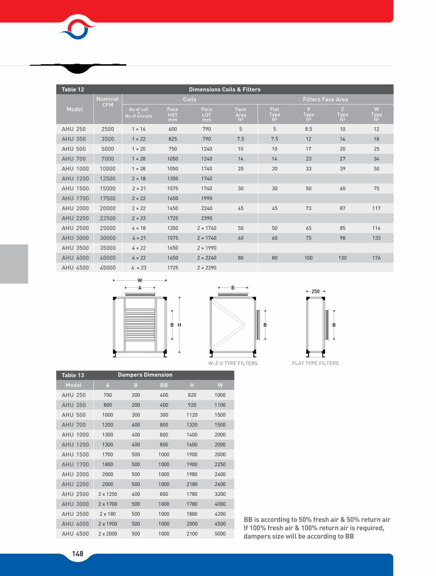
148
BB is according to 50% fresh air & 50% return airIf 100% fresh air & 100% return air is required, dampers size will be according to BB
No of coil ×
No of circuitsFace HGT mm
LGT Area ft²
Flat Type
V Z W
1 × 16 600 790 5 5 8.5 10 12
1 × 22 825 790 7.5 7.5 12 14 18
1 × 20 750 1240 10 10 17 20 25
1 × 28 1050 1240 14 14 23 27 34
1 × 28 1050 1740 20 20 33 39 50
2 × 18 1350 1740
2 × 21 1575 1740 30 30 50 60 75
2 × 22 1650 1990
2 × 22 1650 2240 45 45 73 87 117
2 × 23 1725 2390
4 × 18 1350 2 × 1740 50 50 65 85 114
4 × 21 1575 2 × 1740 60 60 75 98 133
4 × 22 1650 2 × 1990
4 × 22 1650 2 × 2240 80 80 100 130 176
4 × 23 1725 2 × 2390
250 2500
350 3500
500 5000
700 7000
1000 10000
1200 12500
1500 15000
1700 17500
2000 20000
2200 22500
2500 25000
3000 30000
3500 35000
4000 40000
AHU
AHU
AHU
AHU
AHU
AHU
AHU
AHU
AHU
AHU
AHU
AHU
AHU
AHU
AHU 4500 45000
Model
Nominal CFM
Table 12 Dimensions Coils & Filters
Coils Filters Face Area
Face
mm
Face
ft²Type
ft²Type Type
ft² ft²
A B BB H W
700 200 400 820 1000
800 200 400 920 1100
1000 300 300 1120 1500
1200 400 800 1320 1500
1300 400 800 1400 2000
1300 400 800 1600 2000
1700 500 1000 1900 2000
1800 500 1000 1900 2250
2000 500 1000 1980 2400
2000 500 1000 2180 2400
2 x 1250 400 800 1780 3200
2 x 1700 500 1000 1780 4000
2 x 180 500 1000 1880 4200
2 x 1900 500 1000 2000 4500
2 x 2000 500 1000 2100 5000
250
350
500
700
1000
1200
1500
1700
2000
2200
2500
3000
3500
4000
AHU
AHU
AHU
AHU
AHU
AHU
AHU
AHU
AHU
AHU
AHU
AHU
AHU
AHU
AHU 4500
Model
Table 13 Dampers Dimension
W-Z-V TYPE FILTERS FLAT TYPE FILTERS

149
Water Pressure Reduction in Tubes (Feet Water)
0.5 1 1.5 2 2.5 3 3.5 4 5 6 7 8
Cont. Table 1
Water Velocity Feet Per Sec. 2 Row
0.5
0.5
1
1
1.5
1.5
2
2
2.5
2.5
3
3
3.5
3.5
4
4
5
5
6
6
7
7
8
8
Cont. Table 1
Cont. Table 1
Water Velocity Feet Per Sec. 3 Row
Water Velocity Feet Per Sec. 4 Row
0.5 1 1.5 2 2.5 3 3.5 4 5 6 7 8
0.11 0.29 0.53 0.8 1.13 1.44 1.82 2.22 3.04 4 4.95 6.06
0.14 0.36 0.65 0.95 1.35 1.75 2.2 2.7 3.7 4.75 5.9 7.3
0.16 0.42 0.75 1.02 1.6 2.08 2.62 3.16 4.38 5.73 7.17 8.85
0.17 0.45 0.8 1.2 1.7 2.25 2.8 3.4 4.7 6.2 7.7 9.25
0.2 0.49 0.88 1.3 1.85 2.43 3.03 3.67 5.1 6.68 8.36 10.32
0.18 0.5 0.9 1.35 1.9 2.5 3.15 3.8 5.3 6.9 8.7 10.7
0.13 0.34 0.62 0.92 1.31 1.7 2.14 2.61 3.58 4.68 5.82 7.12
0.15 0.41 0.75 1.1 1.56 2.04 2.55 3.12 4.3 5.57 6.9 8.54
0.18 0.49 0.88 1.29 1.85 2.4 2.95 3.66 5.13 6.7 8.38 10.35
0.2 0.53 0.95 1.42 2.01 2.63 3.3 4 5.55 7.25 9.5 11.2
0.21 0.57 1.02 1.51 2.05 2.83 3.54 4.28 5.97 7.81 9.78 12.07
0.21 0.58 1.05 1.56 2.25 2.95 3.7 4.45 6.2 8.81 10.2 12.06
0.17 0.45 0.82 1.23 1.74 2.26 2.86 3.52 4.82 6.3 7.85 9.66
0.21 0.55 1 1.48 2.13 2.8 3.48 4.3 5.9 7.7 9.65 11.95
0.24 0.67 1.16 1.8 2.54 3.33 4.21 5.15 7.15 9.37 11.7 14.15
0.26 0.73 1.3 1.95 2.75 3.6 4.55 5.6 7.8 10.2 12.7 15.75
0.28 0.79 1.4 2.07 2.98 3.9 4.93 6.05 8.4 11.05 13.8 16.7
0.29 0.85 1.45 2.15 3.1 4.1 5.15 6.3 8.75 11.5 14.4 17.85
0.21 0.56 1.02 1.51 2.17 2.83 3.57 4.42 6.05 7.9 9.92 12.2
0.26 0.7 1.25 1.87 2.7 3.5 4.4 5.45 7.45 9.8 12.25 15.2
0.29 0.85 1.51 2.23 3.21 4.22 5.36 6.6 9.15 12 15 18.63
0.32 0.93 1.65 2.45 3.5 4.6 5.8 7.2 10 13.1 16.4 20.3
0.35 1.01 1.78 2.62 3.81 4.98 6.32 7.76 10.83 14.24 17.83 22.09
0.36 1.06 1.85 2.72 3.96 5.22 6.6 8.1 11.3 14.85 18.6 23.1
AHU 250, 350
AHU 500, 700
AHU 1000, 1200, 1500, 2500, 3000
AHU 1700, 3500
AHU 2000, 4000
AHU 2200, 4500
Model
AHU 250, 350
AHU 250, 350
AHU 500, 700
AHU 500, 700
AHU 1000, 1200, 1500, 2500, 3000
AHU 1000, 1200, 1500, 2500, 3000
AHU 1700, 3500
AHU 1700, 3500
AHU 2000, 4000
AHU 2000, 4000
AHU 2200, 4500
AHU 2200, 4500
Model
Model
AHU 250, 350
AHU 500, 700
AHU 1000, 1200, 1500, 2500, 3000
AHU 1700, 3500
AHU 2000, 4000
AHU 2200, 4500
Model
Table 1
Water Velocity Feet Per Sec. 1 Row

150
Water Pressure Drop in Tubes (Feet Water)
Coil Water Side Pressure Drop Correction Factor Temperature Gradient
-Actual water side PD = PD (Table 5) × CF (Table 5 cont.)
0.5 1 1.5 2 2.5 3 3.5 4 5 6 7 8
AHU 250, 350
AHU 500, 700
AHU 1000, 1200, 1500, 2500, 3000
AHU 1700, 3500
AHU 2000, 4000
AHU 2200, 4500
Model
Cont. Table 1
Water Velocity Feet Per Sec. 8 Row
0.5 1 1.5 2 2.5 3 3.5 4 5 6 7 8
AHU 250, 350
AHU 500, 700
AHU 1000, 1200, 1500, 2500, 3000
AHU 1700, 3500
AHU 2000, 4000
AHU 2200, 4500
Model
Table 1
Water Velocity Feet Per Sec. 6 Row
0.29 0.8 1.44 2.13 3.08 4.03 5.05 6.2 8.54 11.28 14.07 17.35
0.36 0.98 1.8 2.65 3.83 5 6.3 7.77 10.7 14.14 17.78 21.93
0.43 1.18 2.19 3.2 4.7 6.11 7.73 8.8 13.21 17.4 22.9 27.04
0.48 1.3 2.4 3.5 5.1 7.65 8.4 10.35 14.4 19 24 30
0.52 1.39 2.56 3.78 5.53 7.25 9.15 11.26 15.66 20.7 26.11 32.2
0.54 1.45 2.7 3.95 5.8 7.6 9.65 11.8 16.5 21.7 27.44 33.75
0.38 1.04 1.86 2.73 3.97 5.23 6.53 7.98 11.03 14.65 18.22 22.5
0.46 1.23 2.28 3.41 4.98 6.57 8.22 10.1 13.96 18.48 23.05 28.6
0.57 1.51 2.82 4.18 6.1 8 10.1 12.4 17.37 22.81 28.85 35.4
0.64 1.64 3.1 4.55 6.65 8.7 11 13.55 18.9 24.9 31.5 38.8
0.69 1.78 3.35 4.95 7.25 9.52 12 14.76 20.5 27.16 34.4 42.31
0.71 1.85 3.5 5.2 7.65 10 12.7 15.5 21.6 28.6 36.3 44.4
40 50 60 80 100 120 140 150 160 180 200 220
1.04 1 0.96 0.9 0.86 0.83 0.8 0.78 0.77 0.76 0.74 0.73
Cont. Table 1
Average Water Temperature � F
Correction Factor

151
POSITIVE PRESSURE TRAPPING
K = MIN. ½”H = ½” PLUS MAXIMUMTOTAL STATIC PRESSURE
NEGATIVE PRESSURE TRAPPING
K = (1” FOR EACH 1” OF MAXIMUMNEGATIVE STATIC PRESSURE)J = HALF OF HL = H + J + PIPE DIAMETER + INSULATION
Connection Size
Drain Pan Trapping
* Right Handed Connection Are Shown
Chilled Water Hot Water Steam
4 Rows
Supply Condenser
250
350
500
700
1000
1200
1500
1700
2000
2200
2500
3000
3500
4000
AHU
AHU
AHU
AHU
AHU
AHU
AHU
AHU
AHU
AHU
AHU
AHU
AHU
AHU
AHU 4500
Model
Table 15 Chilled & Hot water & Steam coil Connection
6 Rows 8 Rows 1 Rows 2 Rows 3 Rows 4 Rows 1 Rows 1 Rows2 Rows 2 Rows
1 ¼"
1 ½"
1 ½"
2 "
2 "
2*2"
2*2"
2*2 ½"
2*2 ½"
2*2 ½"
4*2"
4*2"
4*2 ½"
4*2 ½"
4*2 ½"
1 ½"
2 "
2 "
2 "
2 ½ "
2*2 "
2*2 "
2*2 ½"
2*2 ½"
2*2 ½"
4*2 "
4*2 "
4*2 ½"
4*2 ½"
4*2 ½"
1 ½"
2 "
2 "
2 ½"
2 ½"
2*2 ½"
2*2 ½"
2*2 ½"
2*2 ½"
2*2 ½"
4*2 ½"
4*2 ½"
4*2 ½"
4*2 ½"
4*2 ½"
1"
1 ¼"
1 ¼"
1 ½"
1 ½"
2*2 ½"
2*2 ½"
2*2 ½"
2*2 ½"
2*2 ½"
4*2 ½"
4*2 ½"
4*2 ½"
4*2 ½"
4*2 ½"
1"
1 ¼"
1 ¼"
1 ½"
1 ½"
2*2 ½"
2*2 ½"
2*2 ½"
2*2 ½"
2*2 ½"
4*2 ½"
4*2 ½"
4*2 ½"
4*2 ½"
4*2 ½"
1 ¼"
1 ½"
1 ½"
2 "
2 "
*2 2"
*2 2"
*2 2"
*2 2"
*2 2"
*4 2"
*4 2"
*4 2"
*4 2"
*4 2"
1 ¼"
1 ½"
1 ½"
2 "
2 "
*2 2"
*2 2"
2*2 ½"
2*2 ½"
2*2 ½"
*4 2"
*4 2"
4*2 ½"
4*2 ½"
4*2 ½"
1 ½"
1 ½"
2 "
2 "
2 "
*2 2"
*2 2"
*2 2"
*2 2"
*2 2"
*4 2"
*4 2"
*4 2"
*4 2"
*4 2"
1 ½"
1 ½"
2 "
2 "
2 "
*2 2"
*2 2"
*2 2"
*2 2"
*2 2"
*4 2"
*4 2"
*4 2"
*4 2"
*4 2"
1 ¼"
1 ¼"
1 ½"
1 ½"
1 ½"
2*2 ½"
2*2 ½"
2*2 ½"
2*2 ½"
2*2 ½"
4*2 ½"
4*2 ½"
4*2 ½"
4*2 ½"
4*2 ½"
1 ¼"
1 ¼"
1 ½"
1 ½"
1 ½"
2*2 ½"
2*2 ½"
2*2 ½"
2*2 ½"
2*2 ½"
4*2 ½"
4*2 ½"
4*2 ½"
4*2 ½"
4*2 ½"
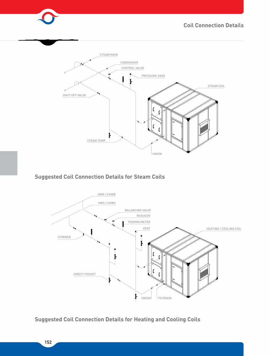
152
Coil Connection Details
Suggested Coil Connection Details for Heating and Cooling Coils
Suggested Coil Connection Details for Steam Coils
STEAM MAIN
CONDENSER
CONTROL VALVE
PRESSURE GAGE
SHUT OFF VALVE
STEAM TEMP
UNION
STEAM COIL
HWR / CHWR
HWS / CHWS
BALANCING VALVE
REDUCER
THERMO METER
VENT
STMINER
DIRECT POCKET
TO DRAIN
HEATING / COOLING COIL
UNION

153
Connection Size
AIR SIDE PRESSURE REDUCTION ACCESSORIES (IN.W.G)
Note:In order to determine air-side coil pressure drop for cases where the number of fins per inch are greater than 8 Fpi, multiply the values by the corresponding correction factor given in the table above.
300 350 400 450 500 550 600 650 700 800
0.037 0.050 0.065 0.081 0.099 0.120 0.156 0.182 0.235 0.325
Filters
Table 16
Face Velocity FPM
Air Filter Pressure Drop (in.w.g)
Cleanable
300 400 500 600 700 800
Wet Dry Dry
8
1 0.05 0.07 0.07 0.1 0.10 0.14 0.14 0.19 0.22
2 0.09 0.14 0.15 0.2 0.22 0.29 0.3 0.39 0.48
3 0.11 0.2 0.16 0.31 0.28 0.44 0.39 0.5 0.62
4 0.15 0.25 0.24 0.4 0.35 0.58 0.48 0.61 0.77
6 0.24 0.39 0.34 0.61 0.52 0.85 0.71 0.92 1.15
8 0.30 0.5 0.47 0.82 0.71 1.05 0.95 1.18 1.46
Fin Per Inch
Table 17
Face Velocity FPM
Coil Face Velocity
RowsDeep
DryDryWetWet DryDry
Cont. Table 17 PD Correction Factor
Coil Fpi
8 10 12 14
1 1.16 1.32 1.45
DiffuserAir Washer Face &
By pass DamperMixing Box
without FilterElectrical
Heater Eliminator Back Draft Damper Class 4
Model
Table 18 (At 500 FPM Velocity)
Class 6,8
250 -1200 0.03 0.22 0.4 0.210.05 0.06 0.02 0.1 0.2
0.04 0.25 0.45 0.251500 - 4500

154
Flow Rate = GPM * Correction Factor (Table 18)
350 400 450 500 550 600 700 800
0.8 0.88 0.94 1.0 1.05 1.11 1.19 1.28
0.86 0.92 0.96 1.0 1.03 1.06 1.11 1.15
No. Of Rows Fin Per Inch
8 10 12
4 1 1.1 1.19
6 1 1.08 1.15
8 1 1.06 1.1
Table 19 Velocity Correction Factor
Coil Face Velocity
Cooling Coil
Heating Coil
Table 20 Velocity Correction Factor
In order to determine capacity of coils with 10 or 12 Fpi, multiply the capacity Relative to 8 Fpi by the corresponding correction factor given in the table 16.
Note:
Mixture (by Weight) Freezing Point Correction Factor For Cooling Water Ethylene Glycol
100 0 0 1
90 10 -4 1.02
85 15 -6.1 1.03
80 20 -9 1.05
75 25 -12 1.07
70 30 45.6 1.09
65 35 49.4 1.11
60 40 -24 1.14
55 45 29.4 1.17
50 50 36.1 1.2
45 55 -45 1.23
Table 21 Correction Factor For Ethylene Glycol Mixture
Entering Water Temperature �F
Entering Water Temperature �F
2 5 10 15 20 30 40 50 60
0.95 1 1.07 1.14 1.19 1.28 1.35 1.42 1.48
160 180 200 220
0.75 1 1.25 1.5
42 44 45 46
1.09 1.04 1 0.97
Steam Correction Factor
Pressure PSIG
Correction Factor
Table 22
Hot Water Correction Factor
Correction Factor
Table 23
Correction Factor
Table 24 Chilled Water Correction Factor
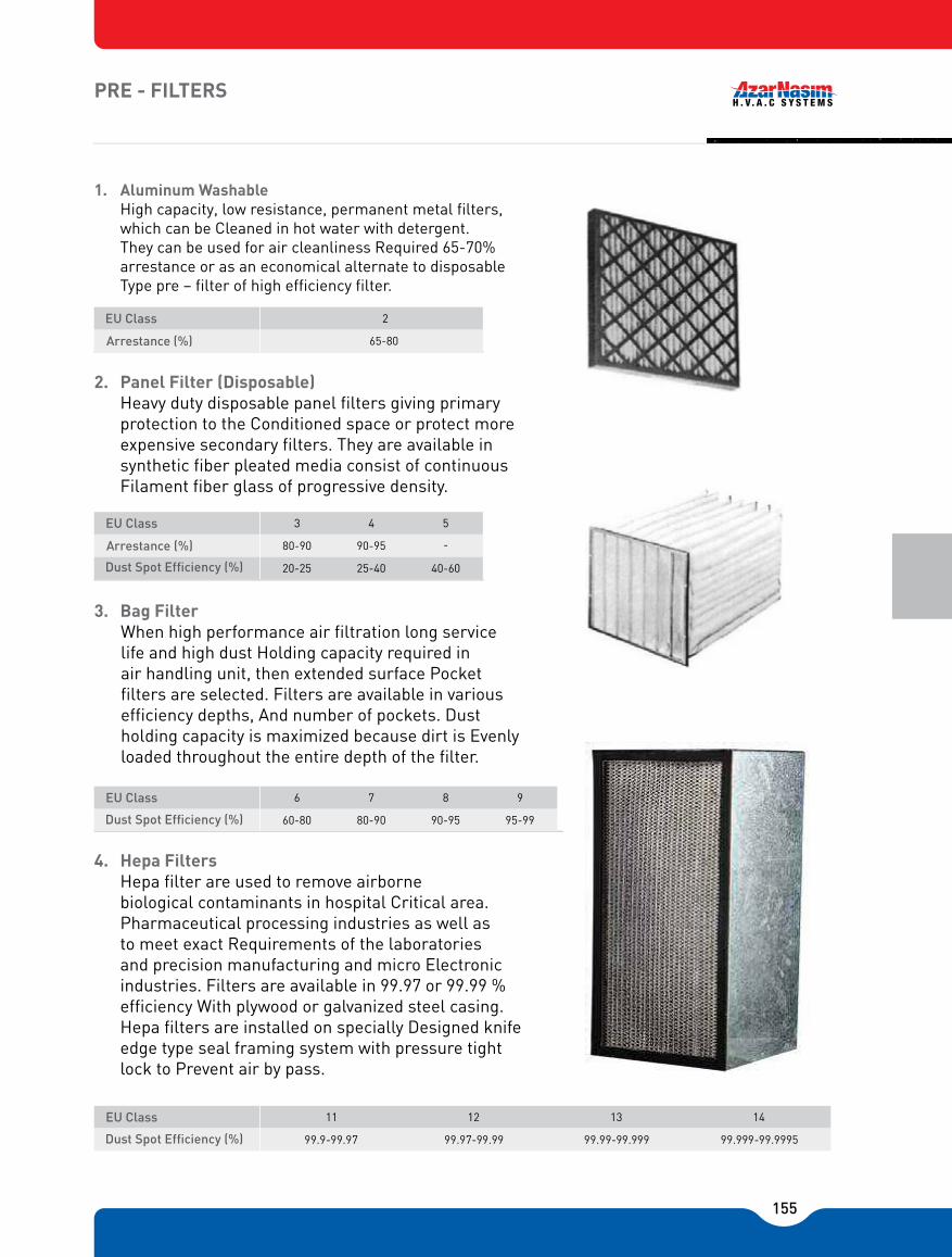
155
PRE - FILTERS
1. Aluminum WashableHigh capacity, low resistance, permanent metal filters, which can be Cleaned in hot water with detergent. They can be used for air cleanliness Required 65-70% arrestance or as an economical alternate to disposable Type pre � filter of high efficiency filter.
2. Panel Filter (Disposable)Heavy duty disposable panel filters giving primary protection to the Conditioned space or protect more expensive secondary filters. They are available in synthetic fiber pleated media consist of continuous Filament fiber glass of progressive density.
3. Bag Filter When high performance air filtration long service life and high dust Holding capacity required in air handling unit, then extended surface Pocket filters are selected. Filters are available in various efficiency depths, And number of pockets. Dust holding capacity is maximized because dirt is Evenly loaded throughout the entire depth of the filter.
4. Hepa FiltersHepa filter are used to remove airborne biological contaminants in hospital Critical area. Pharmaceutical processing industries as well as to meet exact Requirements of the laboratories and precision manufacturing and micro Electronic industries. Filters are available in 99.97 or 99.99 % efficiency With plywood or galvanized steel casing. Hepa filters are installed on specially Designed knife edge type seal framing system with pressure tight lock to Prevent air by pass.
2
65-80
EU Class
Arrestance (%)
EU Class 3 4 5
Arrestance (%) 80-90 90-95
Dust Spot Ef�cency (%) 20-25 25-40 40-60
-
6 7 8 9
60-80 80-90 90-95 95-99
EU Class
Dust Spot Ef�cency (%)
11 12 13 14EU Class
Dust Spot Ef�cency (%) 99.9-99.97 99.97-99.99 99.99-99.999 99.999-99.9995
156
Air Washer Features
Azar Nasim air washers are designed & manufactured in three basic classes.
Class 4:A compact & economical single spray nozzle bank air washer specially designed for effective humidifying and air washing purposes.
Class 6:A single spray nozzle bank unit for medium capacity applications, the ideal air washer for most types evaporative Cooling & air washing tasks.
Class 8:Highly efficient heavy duty units with two spray nozzle banks used whenever the utmost in heat transfer humidification or air cleaning is required.
Casings and water basins are made of galvanized steel sheets. Basins are 300 mm deep for classes 4 & 6, 400 mm deep for class 8.
Moisture eliminators installed side by side in close proximity of each other preventing the water droplets From entering the fan section. They also present a large surface area against which water droplets & dust Particles first impinge before ending up in the basin.
Centrifugal spray nozzles, contain no cores, vanes of obstructions of any kind and all inside surface are Smooth. Nozzles have removable caps which can be taken off for cleaning purposes.
Brass flooding nozzles are installed on separate headers extending across the air washer. They deliver a Solid flat stream of water on to the eliminator surface in order to wash off the dust particles & deposits.
An access door with glass inspection window is available on all models.
Make � up water connection & an automatic float valve which controls the water level in the basin are Provided.
Quick fill connection to which the fresh water supply may be connected is furnished for rapid filling of the Basin.

157
Evaporative Cooling Efficiency (E) / Class 4
Evaporative Cooling Efficiency (E) / Class 6 & 8
Air Washer Performance Factors (P.F)
450 475 500 525 550
0.594 0.572 0.555 0.536 0.519
Table A
Air Velocity
E
0.50 0.55 0.60 0.65 0.70 0.75 0.80 0.85 0.90 0.95 1.0
0.60 0.64 0.68 0.72 0.76 0.80 0.84 0.88 0.92 0.95 1.0
P.F
E
Table B
Model 250 350 500 700 1000 1200
C 6 C 8 C 6 C 8 C 6 C 8 C 6 C 8 C 6 C 8 C 6 C 8
P.F 0.525 0.815 0.525 0.815 0.548 0.821 0.548 0.821 0.548 0.821 0.548 0.821
Table C
17001500 2000 2200 2500 3000
0.571 0.854 0.571 0.854 0.571 0.854 0.571 0.854 0.548 0.821 0.571 0.854
Model
C 6 C 8 C 6 C 8 C 6 C 8 C 6 C 8 C 6 C 8 C 6 C 8
P.F
Cont. Table C
0.571 0.854 0.571 0.854 0.571 0.854
40003500 4500Model
C 6 C 8 C 6 C 8 C 6 C 8
P.F
Cont. Table C
158
Air Washer Selection Procedure
Note:Abbreviations Ent & Lvg. notes air Entering & Leaving air washer.
Given: Entering air DB temperature = 95 ˚FEntering air WB temperature = 63 ˚FSensible cooling load = 85 MBHDesign air flow rate = 10000 CFMRoom DB temperature = 77 ˚F
Determine the required air washer model,Q = 1.085 × CFM × (D.B Room, - D.B Lvg.)
Considering the required air flow rate in CFM & the unit available nominal air flow rate, air handling unit Model AHU�1000 is chosen.Evaporative cooling efficiency (E) is determined as,
D.B. Ent - D.B. Lvg 95 - 69.16E = = = 0.8 D.B. Ent - W.B. Ent 95-63
The coil face area for model 1000 is 20ft² therefore.
10000 F.V = = 500 FPM 20
Considering the air velocity & the values in table (A) the (E) value for Class 4 air washer is equal to 0.555 Which is less than the calculated value therefore Class 4 air washer dose not fulfill the requirement. In This case since the (E) value is known, the (P.F) value from table (B) is determined as being equal to 0.75 Now, considering the unit model AHU � 1000, the (P.F) value & table (C) the (P.F) value for Class 6 airWasher is less than the value calculated therefore; Class 8 washer fulfills therequirement.We also notice that the (P.F) value given is 0.821, the actual (E) value is 0.856 (Table B) the Lvg. Air DB temperature is given as.DB Lvg = DB Ent � E × (D.B Ent � WB Ent) = 95 �0.821 × (95 – 63) = 68.7 ˚FTherefore, the actual air washer cooling capacity is given as.
Q = 1.085 × CFM × (D.B Room � DB Lvg) = 1.085 × 10000 × (77 � 68.7) = 90055 BTU/hr. ~ 90 MBHEntering the metric chart with the leaving air DB & WB temperatures of 68.7 ˚F & 63 ˚F Respectively, the relative humidity of the air is determined to be 73%.
85000 D.B Lvg. = D.B Room =77- = 69.16 F 1.085x1000
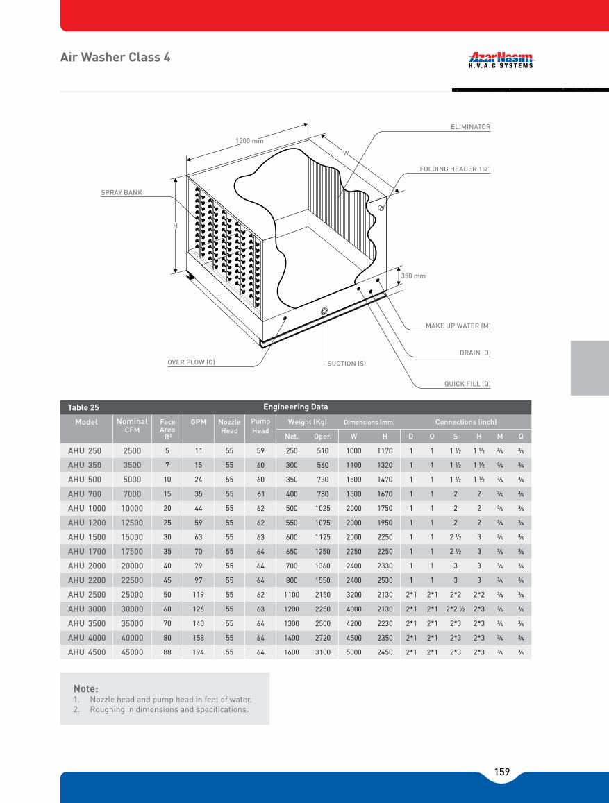
159
Air Washer Class 4
Note:1. Nozzle head and pump head in feet of water.2. Roughing in dimensions and specifications.
Face Area
ft²
GPM Nozzle Head
Pump Head
Net. Oper. W H D O S H M Q
5 11 55 59 250 510 1000 1170 1 1 1 ½ 1 ½ ¾ ¾
7 15 55 60 300 560 1100 1320 1 1 1 ½ 1 ½ ¾ ¾
10 24 55 60 350 730 1500 1470 1 1 1 ½ 1 ½ ¾ ¾
15 35 55 61 400 780 1500 1670 1 1 2 2 ¾ ¾
20 44 55 62 500 1025 2000 1750 1 1 2 2 ¾ ¾
25 59 55 62 550 1075 2000 1950 1 1 2 2 ¾ ¾
30 63 55 63 600 1125 2000 2250 1 1 2 ½ 3 ¾ ¾
35 70 55 64 650 1250 2250 2250 1 1 2 ½ 3 ¾ ¾
40 79 55 64 700 1360 2400 2330 1 1 3 3 ¾ ¾
45 97 55 64 800 1550 2400 2530 1 1 3 3 ¾ ¾
50 119 55 62 1100 2150 3200 2130 2*1 2*1 2*2 2*2 ¾ ¾
60 126 55 63 1200 2250 4000 2130 2*1 2*1 2*2 ½ 2*3 ¾ ¾
70 140 55 64 1300 2500 4200 2230 2*1 2*1 2*3 2*3 ¾ ¾
80 158 55 64 1400 2720 4500 2350 2*1 2*1 2*3 2*3 ¾ ¾
88 194 55 64 1600 3100 5000 2450 2*1 2*1 2*3 2*3 ¾ ¾
250 2500
350 3500
500 5000
700 7000
1000 10000
1200 12500
1500 15000
1700 17500
2000 20000
2200 22500
2500 25000
3000 30000
3500 35000
4000 40000
AHU
AHU
AHU
AHU
AHU
AHU
AHU
AHU
AHU
AHU
AHU
AHU
AHU
AHU
AHU 4500 45000
Model Nominal CFM
Table 25 Engineering Data
Dimensions (mm) Connections (inch)Weight (Kg)
SPRAY BANK
FOLDING HEADER 1�
ELIMINATOR
350 mm
MAKE UP WATER (M)
DRAIN (D)
QUICK FILL (Q)
SUCTION (S)OVER FLOW (O)
1200 mm
W
H

160
Air Washer Class 6
Note:1. Nozzle head and pump head in feet of water.2. Roughing in dimensions and specifications.
5 15 55 59 450 950 1000 1220 1 1 2 1 ½ ¾ ¾
7 22 55 60 500 1000 1100 1370 1 1 2 1 ½ ¾ ¾
10 35 55 60 550 1280 1500 1520 1 1 2 1 ½ ¾ ¾
15 46 55 61 600 1330 1500 1720 1 1 2 2 ¾ 1
20 62 55 62 720 1700 2000 1800 1 1 2 ½ 2 1 1
25 79 55 62 825 1800 2000 2000 1 ½ 1 ½ 3 2 1 1
30 95 55 63 900 1900 2000 2300 1 ½ 1 ½ 3 3 1 1
35 101 55 64 980 2100 2250 2300 1 ½ 1 ½ 3 3 1 1
40 119 55 64 1050 2300 2400 2380 1 ½ 1 ½ 2*2½ 3 1 1
45 143 55 64 1200 2600 2400 2580 1 ½ 1 ½ 2*2½ 3 1 1
50 158 55 62 1650 3600 3200 2180 2*1½ 2*1½ 2*3 2*3 1 1
60 190 55 63 1800 3800 4000 2180 2*1½ 2*1½ 2*3 2*3 1 1
70 202 55 64 1960 4200 4200 2280 2*1½ 2*1½ 2*3 2*3 1 1
80 238 55 64 2100 4600 4500 2400 2*1½ 2*1½ 2*3 2*3 1 1
88 286 55 64 2400 5200 5000 2500 2*1½ 2*1½ 2*3 2*3 1 1
Face Area
ft²
GPM Nozzle Head
Pump Head
Net. Oper. W H D O S H M Q
250 2500
350 3500
500 5000
700 7000
1000 10000
1200 12500
1500 15000
1700 17500
2000 20000
2200 22500
2500 25000
3000 30000
3500 35000
4000 40000
AHU
AHU
AHU
AHU
AHU
AHU
AHU
AHU
AHU
AHU
AHU
AHU
AHU
AHU
AHU 4500 45000
Model Nominal CFM
Table 26 Engineering Data
Dimensions (mm) Connections (inch)Weight (Kg)
SPRAY BANK
FOLDING HEADER 1�
ELIMINATOR
400 mm
MAKE UP WATER (M)
DRAIN (D)
QUICK FILL (Q)
SUCTION (S)OVER FLOW (O)
1800 mm
W
H

161
Air Washer Class 8
22 600 1500 2 2 2 2 ½ ¾ ¾
30 650 1550 2 2 2 2 ½ ¾ ¾
48 720 2050 2 2 2 ½ 2 ½ ¾ 1
70 840 2150 2 2 2 ½ 2*2 ¾ 1
97 950 2750 2 2 3 2*2 1 1
119 1050 2850 2 2 3 2*3 1 1
127 1200 3000 2 2 4 2*3 1 1
143 1375 3400 2 2 4 2*3 1 1
158 1450 3750 2 2 4 2*3 1 1
191 1650 4300 2 2 4 2*3 1 1
238 2100 5700 2*2 2*2 2*3 4*3 1 1
254 2400 6000 2*2 2*2 2*4 4*3 1 1
286 2750 6800 2*2 2*2 2*4 4*3 1 1
316 2900 7500 2*2 2*2 2*4 4*3 1 1
382 3300 8600 2*2 2*2 2*4 4*3 1 1
5 55 59 1000 1220
7 55 60 1100 1370
10 55 60 1500 1520
15 55 61 1500 1720
20 55 62 2000 1800
25 55 62 2000 2000
30 55 63 2000 2300
35 55 64 2250 2300
40 55 64 2400 2380
45 55 64 2400 2580
50 55 62 3200 2180
60 55 63 4000 2180
70 55 64 4200 2280
80 55 64 4500 2400
88 55 64 5000 2500
Face Area
ft²
GPM Nozzle Head
Pump Head
Net. Oper. W H D O S H M Q
250 2500
350 3500
500 5000
700 7000
1000 10000
1200 12500
1500 15000
1700 17500
2000 20000
2200 22500
2500 25000
3000 30000
3500 35000
4000 40000
AHU
AHU
AHU
AHU
AHU
AHU
AHU
AHU
AHU
AHU
AHU
AHU
AHU
AHU
AHU 4500 45000
Model Nominal CFM
Table 27 Engineering Data
Dimensions (mm) Connections (inch)Weight (Kg)
Note:1. Nozzle head and pump head in feet of water.2. Roughing in dimensions and specifications.
SPRAY BANK
FOLDING HEADER �
ELIMINATOR
400 mm
MAKE UP WATER (M)
DRAIN (D)
QUICK FILL (Q)
SUCTION (S)OVER FLOW (O)
2400 mm
W
H

162
Humidifiers
Spray Nozzle Humidifier Electrical Pan Humidifier
�W5 �W10
8 15 1 12 4
12 22 1 18 6
16 31 1 24 8
23 44 1 ¼ 33 10
33 62 1 ¼ 49 16
42 78 1 ¼ 60 20
50 94 1 ¼ 71 24
58 125 2 83 28
66 110 2 95 32
75 156 2*1 ¼ 106 36
83 140 2*1 ¼ 120 40
100 188 2*1 ¼ 142 48
116 220 2*2 116 56
132 250 2*2 190 64
150 280 2*2 212 72
250 2500
350 3500
500 5000
700 7000
1000 10000
1200 12500
1500 1500
1700 17500
2000 20000
2200 22500
2500 25000
3000 30000
3500 35000
4000 40000
AHU
AHU
AHU
AHU
AHU
AHU
AHU
AHU
AHU
AHU
AHU
AHU
AHU
AHU
AHU 4500 45000
Model Nominal CFM
Table 28
Absorbed Moisture HeaderSize
250 2500
350 3500
500 5000
700 7000
1000 10000
1250 12500
1500 1500
1750 17500
2000 20000
2250 22500
2500 25000
3000 30000
3500 35000
4000 40000
AHU
AHU
AHU
AHU
AHU
AHU
AHU
AHU
AHU
AHU
AHU
AHU
AHU
AHU
AHU 4500 45000
Model Nominal CFM
Table 28
Absorbed Moisture KW
13 32 46 64 97 129
18 45 64 89 135 180
26 64 92 127 193 257
36 89 128 178 271 361
52 128 183 255 387 515
65 160 230 318 481 645
79 192 275 382 581 773
92 223 320 445 677 900
105 256 367 510 775 1030
118 288 412 573 870 1158
130 320 460 636 962 1290
158 384 550 764 1162 1546
184 246 640 890 1354 1800
210 512 734 1020 1550 2060
236 576 824 1146 1740 2316
�W10
250 2500
350 3500
500 5000
700 7000
1000 10000
1200 12500
1500 1500
1700 17500
2000 20000
2200 22500
2500 25000
3000 30000
3500 35000
4000 40000
AHU
AHU
AHU
AHU
AHU
AHU
AHU
AHU
AHU
AHU
AHU
AHU
AHU
AHU
AHU 4500 45000
Model Nominal CFM
Table 29
�W10 �W10 �W10 �W10 �W10
Steam Capacity (Lb. /hr.)
• Δ W: Moisture difference between air after & before humidifier (Grain / Lb.(of dry air))• Drain size = 0.5 inch
Note:
• Δ W: Moisture difference between air after & before humidifier (Grain / Lb.(of dry air))• Steam humidifier rating at 5 PSI pressure.
Note:

163
Service Area Requirements
Note:• All Dimensions in mm
Single Zone Horizontal
Multi - Zone
Air Washer
Model AHU 250
AHU 350
AHU 500
AHU 700
AHU 1000
AHU 1200
AHU 1500
AHU 1700
AHU 2000
AHU 2200
AHU 2500
AHU 3000
AHU 3500
AHU 4000
AHU 4500
A 70 70 80 80 100 100 100 100 120 120 210 210 235 260 275
B 100 100 100 100 100 100 100 100 120 120 210 210 235 260 275
C 110 110 160 160 210 210 210 210 260 275 210 210 235 260 275
Table 30 Dampers Dimension
Pos AHU 250
AHU 350
AHU 500
AHU 700
AHU 1000
AHU 1200
AHU 1500
AHU 1700
AHU 2000
AHU 2200
AHU 2500
AHU 3000
AHU 3500
AHU 4000
AHU 4500
A 70 70 80 80
B
100 100 100 100 120 120 210 210 235 260 275
110 110 160 160 210 210 210 210 260 275 210 210 235 260 275
Table 31
Model
Dampers Dimension
C
100B
60
B
100A
60
B
100A
100

164
Enthalpy / Altitude
511141113111211111111
13.913.713.513.313.213.03514.514.214.013.813.513.43614.814.714.414.314.013.93715.315.115.014.714.514.23815.915.615.415.215.014.83916.416.215.915.715.415.24016.816.616.416.115.915.74117.417.216.916.616.416.24218.017.617.417.116.916.64318.518.217.917.617.417.24419.018.718.418.217.917.74519.619.319.018.718.418.24620.219.819.519.318.918.74720.820.420.019.819.519.24821.321.020.620.420.019.74922.321.621.220.920.620.35022.622.221.821.521.220.951
23.222.822.522.121.721.45224.023.523.122.722.422.05324.624.123.823.423.022.65425.324.824.424.023.623.255
25.925.525.024.624.223.856
26.726.225.825.324.824.457
27.426.926.425.925.525.25828.227.627.226.726.225.85928.928.427.827.426.926.56029.729.228.628.127.627.26130.529.929.428.928.327.96231.430.730.229.629.028.56332.231.631.030.329.829.36433.032.331.731.230.630.16533.933.332.632.031.430.866
34.834.133.532.832.231.667
35.835.034.333.733.032.468
36.735.935.334.533.933.269
37.636.936.135.434.734.070
38.637.937.036.335.634.971
39.738.838.037.336.535.872
40.739.939.038.237.536.773
41.840.940.039.238.437.674
42.942.041.040.239.438.675
44.043.042.141.240.339.676
45.242.243.242.341.440.677
46.445.344.343.442.541.578
47.546.545.544.543.542.679
48.847.646.645.644.643.780
50.048.847.846.745.844.881
51.450.349.048.046.945.982
52.851.550.349.248.147.083
54.252.951.650.449.348.284
55.654.253.051.750.349.485
Air Wet Bulb Temp.°F
Table 32
Altitude (ft.)
Enthalpy (BTU / Lb.)
165
NDNR

166
Condencer
FeaturesGeneral Azar Nasim Air cooled Condensers are offered in 12 models with refrigeration capacity range of 18.6 to 2017 MBH, designed to accommodate a wide range of applications in the A/C industry.
CasingProper thickness galvanized steel sheets are used in the structure of casing panels and mounting legs formed from heavy steel sheets which are joined by bolts offer maximum rigidity and facilitate repairing.
CoilsCondenser coils consist of seamless cooper tubes mechanically expanded into die formed aluminum or copper fins with 10, 12, 14 FPI spacing. Coils are available in single and multi-circuits.
FansDirectly driven axial fans, deliver the required air flow rate at minimum sound levels. All fans are equipped with fan guard for maximum protection. Fan operation sequencing is performed based on the liquid refrigerant’s pressure leaving the condenser.
MotorsTotally enclosed air cooled (air over body) electric motors equipped with permanently lubricated bearings, an IP-55 protection, winding insulation class of (F) plus thermal protection and B rise construction are mounted in vertical position. The motors are suitable for operation.
Electrical PanelConsists of a drip proof panel enclosing all electric components such as contactors, over load protections and �
TestingCondenser coils have passed the leakage test 450 psig after production and the entire condenser unit has tested at 350 psig working pressure after completion.

167
Selection Procedure
Helpful HintsMaximum allowable condensing temperature for R-22 & R 407 C : 135 ˚FOptimum condensing temperature for R-22 & R 407 C : 120 ˚FTD: Condensing temperature � Ambient dry bulb temperature.THR = [System cooling capacity] + [Compressor motor power input x 3413].When compressor motor power in the formula above is not known use values from table 8 in the following relationship:THR = [System cooling capacity] x [Heat of compression factor]
Example 1Given:System cooling capacity: 210000 BTU/Hr.Condensing temperature: 120 ˚FAmbient air temperature: 100 ˚FCompressor power input: 18.2 KwDesign altitude: 2000 FtCoil fin per inch: 14 FPIFin material: Aluminum
Select matching air cooled condenserDetermine Total Refrigeration:THR = 210000 + (18.2 x 3413) = 272117 BTU/Hr.From Table 2 for altitude adjustment factor (@ 2000 Ft) AF = 1.05Adjusted THR = (1.05) (272117) = 285723 BTU/Hr.TD ( Design temperature difference ) = ( 120 �100) =20 ˚FFrom table (4) and TD of 20 ˚F. ANC 250 with plate fins offers 273000 BTY/Hr. which fulfills the above required THR.
Example 2Given:System Total Heat Rejection ( THR ): 350000 BTU/Hr.Condensing temperature: 120 ˚FAmbient air temperature: 100 ˚FAltitude: 4000 FtCoil fin per inch: 10 FPIFin material: CopperRefrigerant: R 22
Select matching air cooled condenserTD: Cond Temp - Ambient Temp = 120-100 = 20 ˚FTotal Heat Rejection Requirement = THR x Correction Factor (Table 10) / Correction Factor (Table 9) = 350000 x 1.10/085 = 452941 BTU/Hr. = 452.941 MBH from Table (10) and T.D of 20 ˚F, ANC-450 offers.

168
Dimensions for All Condensers
050 060 120 180 250 350 450 550 700 850 1000 1200
L 900 1300 1500 1950 2500 2500 3000 3000 4300 5300 6300 6300
W 830 1000 1200 1210 1450 1950 1950 2400 2400 2400 2400 2400
H 1250 1250 1250 1250 1250 1250 1250 1250 1250 1250 1250 1250
H 600 600 600 600 600 600 600 600 600 600 600 600
Model
Table 1 Dimensions
Anc Anc Anc Anc Anc Anc Anc Anc Anc Anc Anc Anc
1
A 1200 1400 1600 1600 1600 1600 1600 1600 1600 1600 1600 1600
B 1100 1100 1100 1300 1300 1300 1300 1300 1300 1300 1300 1300
Model
Table 2 Dimensions
Anc Anc Anc Anc Anc Anc Anc Anc Anc Anc Anc Anc
050 060 120 180 250 350 450 550 700 850 1000 1200
L
H
H1ELEC
TRIC
AL
PAN
EL
LIFTING EYES
HOT GAS ENT.
SAFETY VALVE
LIQ. OUTLET NO. 2
LIQ. OUTLET NO. 1
ONLY IN LARGER MODELS LIQ. INLETRECIVER
DRAIN PLUG
AB
W
CO
IL C
OVE
R P
LATE
SERVICE VALVECHARGE VALVE
150
A
B
1. All dimensions in mm. 2. Given (K) & (L) valves are the minimum allowable.Note:

169
Piping Recommendations
Note:1. All horizontal piping segments must be sloped 1/2
In. per each 10 Ft. of Length in the direction of flow.
2. For proper oil return back to compressor. Install air cooled condenser a minimum of (1m) above the compressor.
Note:1. Table values are applicable for condensing
temperatures of 80 to 135 ˚F.
2. Given sizes are nominal and may be modified with design condition and the physical characteristics compressors used.
Btu/Hr. 50 100 150 200 50 100 150 200
18 000 5/8 5/8 5/8 7/8 3/8 3/8 1/2 1/2
24 000 5/8 7/8 7/8 7/8 3/8 1/2 1/2 1/2
36 000 7/8 7/8 7/8 7/8 1/2 1/2 1/2 1/2
48 000 7/8 7/8 7/8 1 1/8 1/2 5/8 5/8 5/8
60 000 7/8 1 1/8 1 1/8 1 1/8 1/2 5/8 5/8 5/8
75 000 7/8 1 1/8 1 1/8 1 1/8 1/2 5/8 5/8 5/8
100 000 1 1/8 1 3/8 1 3/8 1 3/8 5/8 7/8 7/8 7/8
150 000 1 1/8 1 3/8 1 3/8 1 3/8 7/8 7/8 7/8 7/8
200 000 1 3/8 1 5/8 1 5/8 1 5/8 7/8 7/8 1 1/8 1 1/8
300 000 1 1/3 1 5/8 1 5/8 2 1/8 1 1/8 1 1/8 1 1/8 1 1/8
400 000 1 5/8 2 1/8 2 1/8 2 1/8 1 1/8 1 1/8 1 3/8 1 3/8
500 000 2 1/8 2 1/8 2 1/8 2 1/8 1 1/8 1 3/8 1 3/8 1 3/8
600 000 2 1/8 2 1/8 2 1/8 2 5/8 1 3/8 1 3/8 1 3/8 1 5/8
750 000 2 1/8 2 5/8 2 5/8 2 5/8 1 5/8 1 5/8 1 5/8 1 5/8
Evaporator Inlet OutletCooling Capacity Discharge Line Equivalent Length Ft. Liquid Line Equivalent Length Ft.
Table 3 -Recommended Refrigerant Line Sizes O.D. (inch)
CONDENSERSERVICE VALVE
HOT GASCHECK VALVE
COMPRESSOR SYSTEM WITH CAPACITY REDUCTION
HOT GAS
COMPRESSOR SYSTEM WITHOUT CAPACITY REDUCTION
CONDENSERSERVICE VALVE
CHECK VALVE
HOT GASCHECK VALVE
COMPRESSOR SYSTEM WITH LPNG DISCHARGE RISER
ADDITIONAL TRAP PER EACH 20 Ft OF RISER LENGTH

170
Total Refrigeration for R-22 [MBH]
Note:• MBH = 1000 BTU/hr.• Above given values are based on sea level altitude
and 12 Fins per Inch coils. For different Altitude
and coil FPI (10, 12, 14), multiply THR value by the appropriate correction factor in Table 10 and divide by correction factor in table 9.
ModelT�
10 15 20 25 30
18 29 40 51 62
37 59 81 105 130
67 109 153 200 248
76 120 168 218 271
122 195 273 352 434
149 235 327 426 525
193 309 431 558 690
209 379 529 685 846
309 492 687 893 1193
405 646 902 1167 1440
497 794 1108 1430 1760
575 910 1261 1622 1990
Table 4 Aluminum Fin
Anc 050
060Anc
120Anc
180Anc
250Anc
350Anc
450Anc
550Anc
700Anc
850Anc
1000Anc
1200Anc
Copper Fin
19 29 40 51 63
37 60 83 107 133
69 111 156 205 254
77 123 171 222 276
124 198 277 358 442
151 239 333 432 536
197 313 438 567 702
241 385 538 698 861
314 500 699 908 1123
411 658 918 1188 1465
504 808 1127 1456 1793
583 923 1279 1645 2018
ModelT�
10 15 20 25 30
Table 5
Anc 050
060Anc
120Anc
180Anc
250Anc
350Anc
450Anc
550Anc
700Anc
850Anc
1000Anc
1200Anc
Total Refrigeration

171
Note:• MBH = 1000 BTU/Hr.• Above given values are based on sea level altitude and
12 Fins per Inch coils. For different Altitude and coil FPI
(10, 12, 14), multiply THR value by the appropriate correction factor in Table 10 and divide by correction factor in Table 4.
19 28 38 49 60
35 56 103 127
64 105 149 195 244
74 117 165 215 266
118 191 267 348 429
142 227 318 414 514
187 299 420 547 678
247 368 518 673 834
298 477 672 875 1085
391 630 885 1150 1422
482 777 1091 1414 1743
560 893 1242 1602 1971
ModelT�
10 15 20 25 30
Table 6 Aluminum Fin
Anc 050
060Anc
120Anc
180Anc
250Anc
350Anc
450Anc
550Anc
700Anc
850Anc
1000Anc
1200Anc
79
19 28 39 50 61
36 57 80 105 130
65 107 153 200 249
74 119 166 218 271
120 193 273 353 437
144 231 324 421 525
190 303 427 556 690
233 375 526 685 848
302 485 684 891 1106
397 641 901 1171 1448
489 792 1111 1440 1775
567 905 1260 1626 1999
Copper Fin
ModelT�
10 15 20 25 30
Table 7
Anc 050
060Anc
120Anc
180Anc
250Anc
350Anc
450Anc
550Anc
700Anc
850Anc
1000Anc
1200Anc
Total Rejection for R-407C [MBH]
Total Refrigeration

172
Heat of Compression Factor for refregerant cooled compressors
(Hermetic and Semi-Hermetic)
Coil fin per inch correction factor
Altitude Adjustment factor
C�NNIN P. F
90 100 110 120 130 140
1.40 1.46 1.49 1.57 1.64 1.68
1.36 1.42 1.44 1.51 1.54 1.62
1.32 1.34 1.38 1.43 1.49 1.53
1.26 1.30 1.31 1.39 1.42 1.49
1.21 1.24 1.30 1.33 1.38 1.44
1.19 1.21 1.25 1.27 1.32 1.35
1.16 1.20 1.22 1.25 1.30 1.33
1.14 1.18 1.20 1.23 1.28 1.30
Table 8
ection e. F
-10
0
10
20
30
40
45
50
Table 9
Correction Factor
0.9
1
1.08
No. of FPI
10
12
14
0 1000 2000 3000 4000 5000 6000
1.00 1.03 1.05 1.07 1.10 1.12 1.15
Altitude Ft.
Adjustment Factor
Table 10

173
Engineering Data
Engineering Data Weight of Refrigerant in copper line Kg per 100 Ft
Note:System total operating charge = Chiller or packaged unit operating charge + air cooled condenser operating charge + refrigerator Line operating charge (table 13)
Note:Recommended wire sizes are applicable for distances up 50 meters and maximum ambient temperature of 50C
Model
Table 11
Propeller Fan
Diam. Inch RPM Total CFM Rows Deep Charge Kg
UnitWeight
Kg
No. ofCircuits
Pump downCapacity Kg
Total FaceArea Sq.Ft
Coil Refrigerant R-22
No.
Anc 050
Anc 060
Anc 120
Anc 180
Anc 250
Anc 350
Anc 450
Anc 550
Anc 700
Anc 850
Anc 1000
Anc 1200
1
1
2
2
3
4
5
6
8
10
12
12
20
26
26
26
26
26
26
26
26
26
26
26
950
950
950
950
950
950
950
950
950
950
950
950
3400
7200
14400
14400
21600
28800
36000
43200
57600
72000
86400
84000
3
3
3
3
3
3
3
3
3
3
3
4
7
12
18
24
36
48
60
72
96
121
144
144
3
5
7
9
13
18
22
27
35
44
53
70
9
15
22
32
47
61
73
93
123
152
187
245
1
1
1
1
2 , 1
2 , 1
2 , 1
2 , 1
2 , 1
2 , 1
2 , 1
2 , 1
150
230
300
380
540
800
1030
1190
1680
2000
2350
2690
Loqid-100°F
Hot Gas-120°F
Line SizeO.D (In)
1
1
2
2
3
4
5
6
8
10
12
12
3/4
1
1
1
1
1
1
1
1
1
1
1
1.8
2.25
2.25
2.25
2.25
2.25
2.25
2.25
2.25
2.25
2.25
2.25
0.55
1.08
2.16
2.16
3.24
4.32
5.4
6.48
8.64
10.8
12.96
12.96
1.8
2.25
4.5
4.5
6.75
9
11.25
13.5
18
22.5
27
27
6.0
7.42
14.85
14.85
22.27
29.7
37.12
44.55
59.4
74.25
89.1
89.1
1 x 4
1 x 4
1.5 x 4
1.5 x 4
1.5 x 4
2.5 x 4
2.5 x 4
4 x 4
6 x 4
10 x 4
10 x 4
10 x 4
3/8
1/2
5/8
7/8
1/8 1
3/8 1
5/8 1
1/8 2
5/8 2
1/8 3
5/8 3
1/8 4
Model
Table 12
Propeller Fan
Diam. Inch Total CFM Rows Deep Charge Kg Pump downCapacity Kg
Total FaceArea Sq.Ft
No.
Refrigerant R-22
Anc 050
Anc 060
Anc 120
Anc 180
Anc 250
Anc 350
Anc 450
Anc 550
Anc 700
Anc 850
Anc 1000
Anc 1200
Table 13

174
Installation Recommendations
Note:• Do not place units near hot air or steam exhaust.• Place units so that condenser air is not recirculate.
• All types of shading or over hang must be located at least (4M) above the air cooled condenser.
CONDENSER CONDENSER
1.5
TO 2
.0 M
MIN
.
2.5 M MIN.
1.5
TO 2
.0 M
MIN
.
CONDENSER
1.5 TO 2.0 M MIN. 2.5 M MIN. 1.5 TO 2.0 M MIN.
CONDENSER

175

176
177
NT
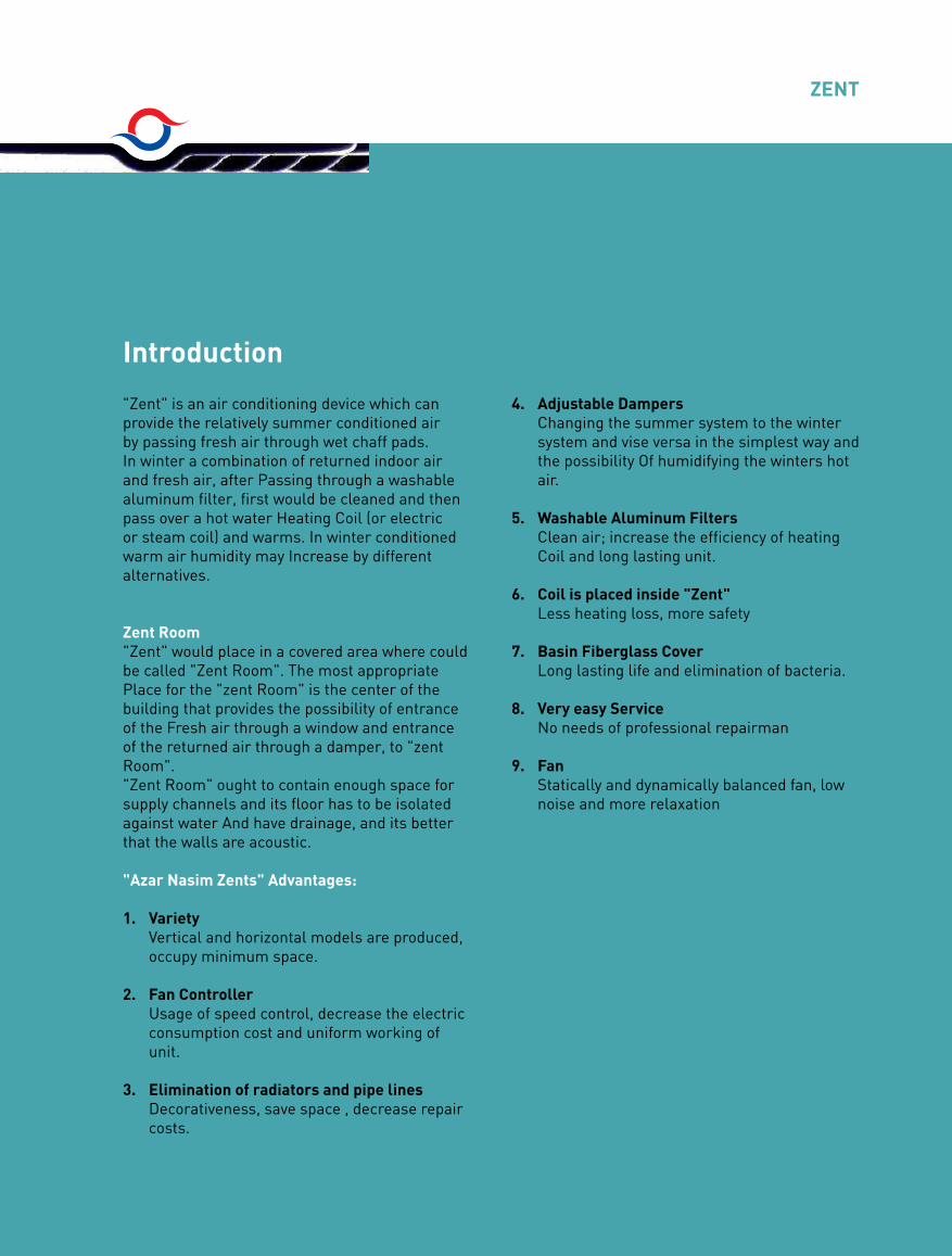
178
ZENT
"Zent" is an air conditioning device which can provide the relatively summer conditioned air by passing fresh air through wet chaff pads. In winter a combination of returned indoor air and fresh air, after Passing through a washable aluminum filter, first would be cleaned and then pass over a hot water Heating Coil (or electric or steam coil) and warms. In winter conditioned warm air humidity may Increase by different alternatives.
Zent Room"Zent" would place in a covered area where could be called "Zent Room". The most appropriate Place for the "zent Room" is the center of the building that provides the possibility of entrance of the Fresh air through a window and entrance of the returned air through a damper, to "zent Room". "Zent Room" ought to contain enough space for supply channels and its floor has to be isolated against water And have drainage, and its better that the walls are acoustic.
"Azar Nasim Zents" Advantages:
1. VarietyVertical and horizontal models are produced, occupy minimum space.
2. Fan ControllerUsage of speed control, decrease the electric consumption cost and uniform working of unit.
3. Elimination of radiators and pipe lines Decorativeness, save space , decrease repair costs.
4. Adjustable DampersChanging the summer system to the winter system and vise versa in the simplest way and the possibility Of humidifying the winters hot air.
5. Washable Aluminum FiltersClean air; increase the efficiency of heating Coil and long lasting unit.
6. Coil is placed inside "Zent"Less heating loss, more safety
7. Basin Fiberglass CoverLong lasting life and elimination of bacteria.
8. Very easy ServiceNo needs of professional repairman
9. FanStatically and dynamically balanced fan, low noise and more relaxation
Introduction

179
Technical Specifications Of C
ooling & H
eating Zent
Type
Model
Approximate
Weight
ConnectionsDim
ensions Total static Pressure
Electromotor
pro�leDim
ensions of Output Span
Fan Diam
eterChaff
Capacity
without
water
FlutterH
ot w
ater
Height
Width
Length
Ht
phase
RPM
Power
A*BW
ater evaporation
Level
Btu/hrCFM
KgInch
cmm
m-H
O²V
HP
cmIn
Lit/hrm
Ø
ABCDEFG
1500
2000
2700
3200
4500
6000
7000
8000
9000
10000
12000
14000
16000
17500
19000
20000
21500
23000
24000
25000
26000
15-50
20-70
27-75
32-85
45-140
60-160
70-190
80-230
90-280
100-320
120-360
140-400
160-440
175-470
190-500
200-570
215-600
200-700
240-730
250-750
260-800
50000
70000
75000
85000
140000
160000
190000
230000
280000
320000
360000
400000
440000
470000
500000
570000
600000
700000
730000
750000
800000
1.15
1.633.5
4.7
5.2
6.2
6.58.7
11.7
1319.325.8
3034.538.5
43525665707580859095100105
12152022252830
34.5 × 40
40 × 37.5
63 × 63
67.5 × 67.5
80 × 80
87 × 87
94 × 87
1/2
3/4
3/4
3/4
1 1/2
3334
5 1/2
5 1/2
7 1/2
2/1 7
1010151515151520
900
1400
220
Threephase
380
192123192320202527303135354042404550505560
90
110
172
172
300
330
360
190
210
255
270
195
215
231
11
1 1/4
1 1/2
1 1/2
1 1/2
1 1/2
3/8
3/8
1/2
1/2
1/2
3/4
3/4
180182185
220225230
460465470
545550555
645655660
790792796
900905915
290292295
320325330
660665670
785790795
960970975
120012021205
140014051415
7085
120
120
140
150
150
Singlephase

180
181
AN IL
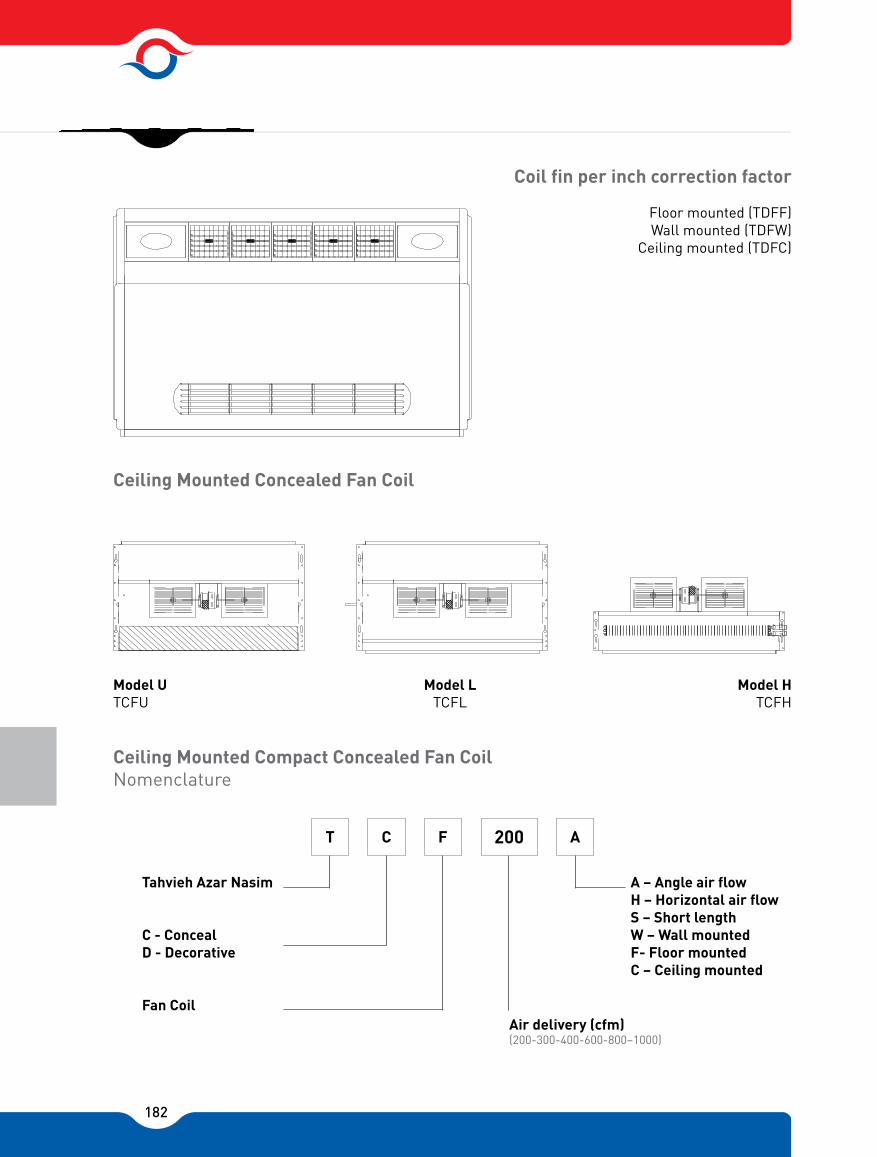
182
Coil fin per inch correction factor
Ceiling Mounted Concealed Fan Coil
Ceiling Mounted Compact Concealed Fan CoilNomenclature
Floor mounted (TDFF)Wall mounted (TDFW)
Ceiling mounted (TDFC)
Model UTCFU
Model LTCFL
Model HTCFH
Tahvieh Azar Nasim
C - Conceal D - Decorative
Fan Coil
A � Angle air flowH � Horizontal air flowS � Short lengthW � Wall mountedF- Floor mountedC � Ceiling mounted
Air delivery (cfm)(200-300-400-600-800�1000)
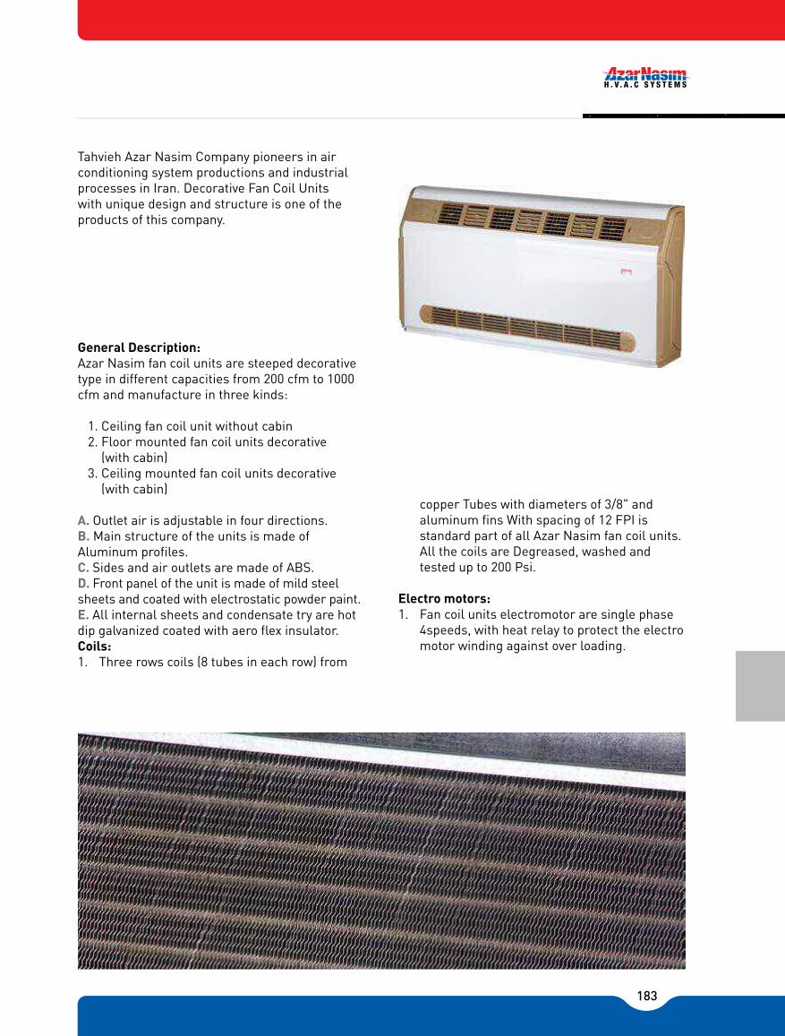
183
Tahvieh Azar Nasim Company pioneers in air conditioning system productions and industrial processes in Iran. Decorative Fan Coil Units with unique design and structure is one of the products of this company.
General Description:Azar Nasim fan coil units are steeped decorative type in different capacities from 200 cfm to 1000 cfm and manufacture in three kinds:
1. Ceiling fan coil unit without cabin2. Floor mounted fan coil units decorative
(with cabin)3. Ceiling mounted fan coil units decorative
(with cabin)
A. Outlet air is adjustable in four directions. B. Main structure of the units is made of Aluminum profiles. C. Sides and air outlets are made of ABS.D. Front panel of the unit is made of mild steel sheets and coated with electrostatic powder paint. E. All internal sheets and condensate try are hot dip galvanized coated with aero flex insulator.Coils:1. Three rows coils (8 tubes in each row) from
copper Tubes with diameters of 3/8" and aluminum fins With spacing of 12 FPI is standard part of all Azar Nasim fan coil units. All the coils are Degreased, washed and tested up to 200 Psi.
Electro motors:1. Fan coil units electromotor are single phase
4speeds, with heat relay to protect the electro motor winding against over loading.

184
Fans:1. Steel or ABS centrifugal fans which statically
and dynamically balanced with low noise level are used.
Filter:1. Air filter is mounted at air inlet with ABS
frame and easily cleanable.
Key Board:1. Electric key board with OFF chassis and 4
speed touch keys (Night mode, 1-2-and 3) is mounted on fan coil units. Remote control can be provided on client’s request.
Intelligent Systems:1. This system installed on the fan coil units to
protect energy wasting. In case of failure of Chiller, Boiler, or circulation pump or air trap in the coil, intelligent system automatically off the fan coil until the problem is solved.

185
Decorative Fan Coil
Exposed Decorative Fan Coil Dimensions
A (mm)
B (mm)
Model
Table 1
200
864
562
540
300
990
687
665
400
1116
812
790
600
1240
937
920
800
1620
1312
1290
1000
1995
1687
1667C (mm)
B
8032
0
600
C
B-(100)
150
Floor mounted Wall mounted
A
A-(360)
610
210

186
Ceiling Mounted Conceal Fan CoilAngle Air flow
562
540
687
665
937
920
1312
1290
1687
1667
Ceiling Mounted Concealed Fan Coil Dimensions
A (mm)
B (mm)
Model
Table 2
200 300 400 600 800 1000
812
790
80
150
170
200
170
100
150
580
A
8032
0
B
(A-100)
8015
0
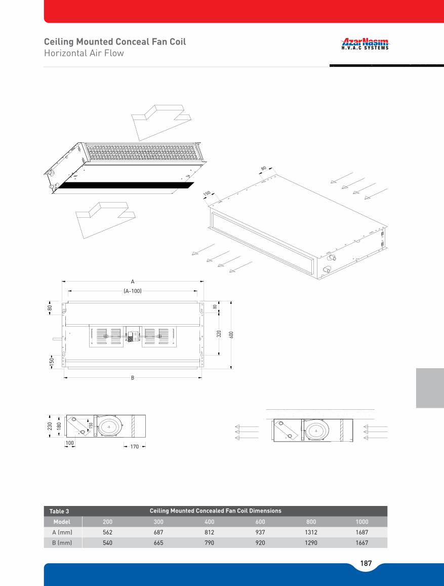
187
Ceiling Mounted Conceal Fan CoilHorizontal Air Flow
562
540
687
665
937
920
1312
1290
1687
1667
Ceiling Mounted Concealed Fan Coil Dimensions
A (mm)
B (mm)
Model
Table 3
200 300 400 600 800 1000
812
790
170
230
180
100
150
A
8032
0
600
B
(A-100)
80
150
150
80

188
Ceiling Mounted Conceal Fan CoilShort length
610 720 1050 1380 1600
Ceiling Mounted Concealed Fan Coil Dimensions
A (mm)
B (mm)
Model
Table 4
200 300 400 600 800 1000
940
562 687 937 1312 1687812
150
100
230
180
100
420
300
70
A
B

189
1000800600400300200
1000800600400300200
544530272421
221111
2×4545452525
1.31.050.650.650.40.4
3.172.511.921.631.400.97
3�8 ..
3
12
Table 5 Physical Speci�cations
*Unit Weight (Kg)
Number of Motors
Nominal Power (W)
Total Rated Amps
Coil Face Area (Ft)
Tube Size
No of Rows
No of Fins/Inch
Nomainal Air Flow Rate (Cfm)
DescriptionUnit Size
2×45
HeatingCoolingAir Flow(Cfm)
Model
Water Flow(Gpm)
Capacity(Btu/Hr)
Water Flow(Gpm)
Sensible Cap.(Btu/Hr)
Total Cap.(Btu/Hr)
2.5218002.062509200200T CFA -200
3.5307502.5870011800300T CFA -300
4.0387503.51225015400400T CFA -400
5.0482504.01475019700600T CFA -600
6.5627505.01825024400800T CFA -800
7.5750006.523250305001000T CFA -1000
Table 6 Nominal Performance Data
*Unit weights giving are for exposed models. For concealed reduce values by approximately35%
Note:1. Capacities are based on high fan speed.2. Cooling capacities are based on entering water at 45 F
and entering air at 80 F D.B., 67 F W.B.
3. Heating capacities are based on entering air at 70 F D.B. entering and leaving water at 180 F and 160 F respectively.

190
MOTOR SPEED CORRECTION FACTOR
MEDIUM 0.90
LOW 0.80
PressureDownfall (F.T.W.G)
67WB. 80DB65 WB. 77DB63 WB 75 DB.
Total(BTU/hr.)
Sensible TotalSensible TotalSensible
9400 6500 8450 6200 7600 6000 10400 7000 9250 6700 8200 6500 110007500 9800 7200 8800 7000 8700 6000 7700 5700 6800 5500 9400 6500 8450 6200 7600 6000
10000 7000 9100 6700 8200 6500 8000 5500 7000 5000 6200 4500 8600 6000 7500 5500 6600 5000 9400 6500 8300 6000 7300 5500
12000 9000 10900 8400 9800 8000 13100 9500 11900 8700 10800 8500 13700 10000 12350 9400 11200 9000 11000 8500 9900 8000 8900 7500 12000 9000 10700 8500 9600 8000 12800 9500 11350 9000 10100 8500 10000 8000 8900 7200 7900 6500 11000 8500 9700 7700 8600 7000 11600 9000 10200 8200 9000 7500 15800 11500 14200 11000 12900 10500 16600 1200015000 11500 13500 11000 17400 1250015700 12000 14200 11500 14400 11500 13000 10700 11600 10000 15400 12000 13700 11200 12200 10500 16000 12500 14350 11700 12800 11000 13400 11000 11800 9700 10400 9000 14000 11500 12400 10400 10900 9500 14800 12000 13000 10900 11400 10000 21000 15500 18900 14200 17000 13000 21900 16000 19800 14700 17900 13500 22800 16500 20600 15200 18600 14000 194001450017300 13500 15400 12500 2040015000 18200 14000 16200 13000 21000 15500 18850 14400 16800 13500 17800 14000 15650 12700 13700 11500 18800 14500 16500 13200 14400 12000 19600 15000 17200 13700 15000 12500 26400 20500 24000 19000 21600 17500 27200 21000 24600 19500 22300 18000 28000 21500 25300 20000 22800 18500 24400 18000 22000 17500 19800 17000 25200 18500 22650 18000 20400 17500 26000 19000 23300 18400 20900 18000 22600 17500 20000 16200 17400 15000 23400 18000 20800 16700 18400 15500 24100 18500 21300 17200 18800 16000 33200 25000 30100 23000 27300 21000 34000 25500 30800 23500 27900 21500 34600 26000 31300 24200 28400 22500 31000 23000 28000 21700 25000 20500 31800 23500 28500 22200 25400 21000 32200 24000 28800 22900 25800 22000 28800 22500 25400 20400 22400 18500 29200 23000 25850 20900 22800 19000 30000 2350026500 21400 23300 19500
2.23.65.42.23.65.42.23.65.44.46.59
6.59
9.411
7.6
789
Model
Table 7
Entering air temperature (°F ) Entering watertemperature (�F)
GPM
(BTU/hr.)(BTU/hr.)(BTU/hr.)(BTU/hr.)(BTU/hr.)
4.4
4.4
6.5
6.5
9
9
5.26.34.2
5.26.3
4.2
11.56.5
6.5
9
9
11.5
11.5
5.26.3
4.2
9.4
9.4
11
11
7.6
7.6
7
7
8
8
9
9
1.52
2.51.5
1.5
2
2
2.5
2.52
2.532
2
2.5
2.5
3
32.53
3.52.5
2.5
3.5
3
3
4
3.5
3.5
4.53.54
4.53.5
4.5
4
5
4.5
5.54.5
4.5
6
5
5
6.5
5.5
5.5
76
6
6.5
6.5
7
7
42
44
46
42
42
42
42
42
44
44
44
44
44
46
46
46
46
46
200
300
400
600
800
1000
1. Capacities are based on high fan speed.2. For unit capacities at med. or low speed� multiply table values by the given
correction factor.
Note:
CHILLER WATER RATINGS

191
11500127001400012000132001450012500137001500016500172001800017000177001850017500182001900020500 21200 22000 21000 21700 22500 21500 22000 23000 18000 18700 19500 18500 19200 20000 19000 19700 20500 23500 24500 25500 24000 25000 26000 24500 25500 26500 29000 30200 31500 29500 30700 32000 30000 31200 32500 23000 23700 24500 23500 24200 25000 24000 24700 25500 30500 31500 32500 31000 32000 33000 31500 32500 33500 37500 38200 39000 38000 38700 39500 38500 39200 40000 29000 30200 31500 29500 30700 32000 30000 31200 32500 38000 39000 40000 38500 39500 40500 39000 40000 41000 47000 47700 48500 47500 48200 49000 48000 48700 49500 38500 39700 41000 39000 40200 41500 39500 40700 42000 50000 51000 52000 50500 51500 52500 51000 52000 53000 61000 62200 63500 61500 62700 64000 62000 63200 64500 47000 48200 49500 47500 48700 50000 48000 49200 50500 60000 61200 62500 60500 61700 63000 61000 62200 63500 74000 75000 76000 74500 75500 76500 75000 76000 77000
PressureDownfall (F.T.W.G)
72DB70DB68 DB.
Total(BTU/hr.)
TotalTotal
Model
Table 8
Entering air temperature (°F ) Entering watertemperature (�F)
GPM
(BTU/hr.)(BTU/hr.)
200
300
400
600
800
1000
3.65.47.3
911.415
11.5
1815
6.3
97.5
12.6
16.214.5
10
12.811.5
3.6
3.6
5.4
5.4
7.3
7.3
9
9
11.4
11.4
15
15
11.5
11.518
18
15
15
6.3
6.39
9
7.5
7.5
12.6
12.616.2
16.2
14.5
14.5
10
1012.8
12.8
11.5
11.5
140
160
180
140
160
180
140
160
180
140
160
180
140
160
180
140
160
180
2.532
2.532
2.533
3.543
3.543
3.54
3.54
4.53.54
4.53.54
4.54.55
5.54.55
5.54.55
5.56
6.57
<56.576
6.57
7.58
8.57.58
8.57.58
8.5
1. Capacities are based on high fan speed.2. For unit capacities at med. or low speed� multiply table values by the given
correction factor.
Note: MOTOR SPEED CORRECTION FACTOR
MEDIUM 0.90
LOW 0.80
HOT WATER RATINGS

192

193
DUCTED FAN COIL

194
AZAR NASIM ducted fan-coil units are designed to deliver reliable conditioned air in a wide range of capacities. With delivery rates of 800 to 3000 CFM these units can meet the air conditioning demands of a variety of multi room applications such as apartments, office buildings, hotels and hospitals. For cooling applications, units are Available with capacities ranging from 20 to 100 K Btu/hr. and for heating units with capacities of 60 to 200 K Btu/hr. at standard conditions (80°F DB, 67°F WB) can be utilized . With 3 different models and seven basic, sizes in each model along with the choice of Vertical or horizontal types. The wide selection range offers considerable design versatility.
EASE OF INSTALLATION & MAINTENANCEHorizontal models can be used in cabinet (Exposed) or furred-in (Concealed) applications. Vertical models are built only in exposed free standing models. The low high dimension associated with the horizontal types facilitates easy installation within double ceilings or concealed locations.
Supply air duct collar simplifies field connection to new or existing supply ductwork. Mounting Brackets on each side of the unit allow swift suspension from the ceiling. All wiring and piping connections are located at accessible locations on the unit. Removable bottom panels permit full width access to the mixing box and blower units. Motor-blower unit can be removed in order to expose the entering face of the coil for cleaning purposes. The following design features are incorporated in the construction of AZAR NASIM ducted Fan-coil units.
CABINETAll cabinets are constructed of 1.25 mm galvanized steel sheet with additional paint coating. Panels are insulated with 10 mm polyethylene insulation panel.
FILTERSStandard filter is removable 1" aluminum mesh washable filter.
CONDENSATE DRAIN PANCondensate drain pan is constructed of heavy gauge galvanized sheet metal with the underside Insulated by 3 mm Polyethylene foam. The condensate drain outlet is 3/4 inch O.D. copper tube, Brazed into the condensate drain pan.
COILSCoils are constructed of 5/8 inch O.D. copper tubes with waffled and rippled edge aluminum or copper fins mechanically bonded to the tubes. All coils are leak tested under water with 325 Psig air in accordance with ANSI/ASHRAE 15 Safety Code for Mechanical Refrigeration.
The coils for hot water applications are identical to chilled water coils available in 4 or 6 rows. All DX coils are evacuated and backfilled with 5 Psig dry nitrogen prior to shipment. Electrical coils could also be mounted on any unit. They shall be protected against overheating.
FANSThe fans are direct driven, centrifugal, forward curved, double width wheels. (DWDI) Fans of The units have three speeds level adjusting: Low, Medium and High.
FEATURES & BENERITS
DUCTED FAN COIL
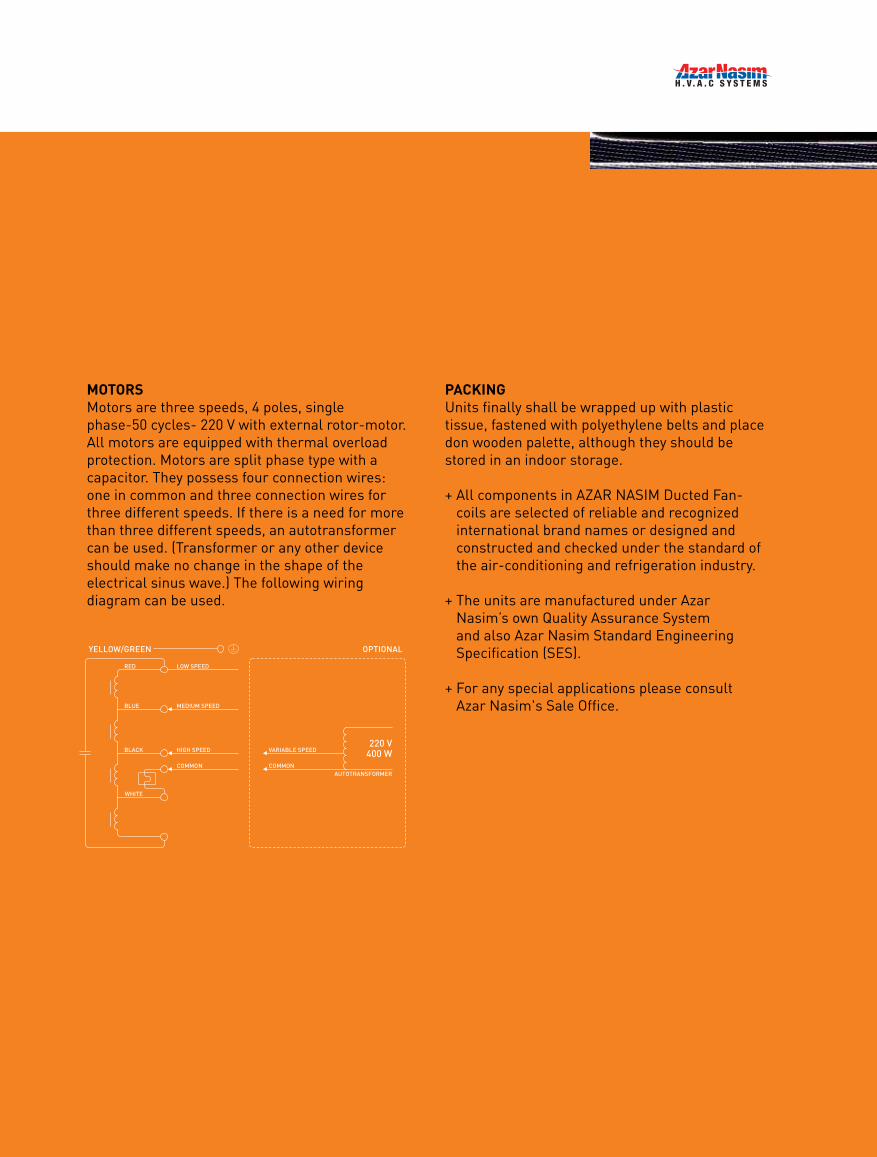
195
MOTORSMotors are three speeds, 4 poles, single phase-50 cycles- 220 V with external rotor-motor. All motors are equipped with thermal overload protection. Motors are split phase type with a capacitor. They possess four connection wires: one in common and three connection wires for three different speeds. If there is a need for more than three different speeds, an autotransformer can be used. (Transformer or any other device should make no change in the shape of the electrical sinus wave.) The following wiring diagram can be used.
YELLOW/GREEN
RED
BLUE
BLACK
WHITE
LOW SPEED
MEDIUM SPEED
HIGH SPEED
COMMON
OPTIONAL
VARIABLE SPEED
COMMONAUTOTRANSFORMER
220 V400 W
PACKINGUnits finally shall be wrapped up with plastic tissue, fastened with polyethylene belts and place don wooden palette, although they should be stored in an indoor storage.
+ All components in AZAR NASIM Ducted Fan-coils are selected of reliable and recognized international brand names or designed and constructed and checked under the standard of the air-conditioning and refrigeration industry.
+ The units are manufactured under Azar Nasim�s own Quality Assurance System and also Azar Nasim Standard Engineering Specification (SES).
+ For any special applications please consultAzar Nasim's Sale Office.

196
Phys
ical
Dat
a an
d So
und
Rat
ings Model
500 400 10 350 56 60 64
600 500 10 350 51 57 60
700 700 10 350 59 63 67
800 700 10 350 59 63 67
900 800 10 350 59 63 67
1050 950 10 350 54 60 63
DF 800
DF 1000
DF 1200
DF 1400
DF 1600
DF 1800
DF 2000
800
1000
1200
1400
1600
1800
2000
2.05
2.45
2.87
3.27
3.68
4.30
4.91
1.64
2.05
2.87
2.87
3.28
3.90
4.51 1200 1100 10
1 ×
1 ×
2 ×
2 ×
2 ×
2 ×
2 × 350
9/7
9/9
9/7
9/7
9/7
9/9
9/9
0.85~3 .2
0.85~3 .2
0.85~3 .2
0.85~3 .2
0.85~3 .2
0.85~3 .2
0.85~3 .2
450~1425
450~1425
450~1425
450~1425
450~1425
450~1425
450~1425 54 63
CFMNominal
Coil Blower & motor Sound Ratings (dB)(Sound Pressure Level at 1m)
Face area (ft²) Finned Length (mm) TubeHigh
No. × BlowerType
(Watt) RPM (Ampere*) Low Medium High
Motor (each)
Water DX Water DX
Tabl
e 1
-PH
YSIC
AL
DAT
A
60* Electrical motor consumption is in the range of 0.85 to 3.2 amps when its rotational speed changes respectively from 450 to 1425 rpm. Any selection should be based on maximum electrical current i.e. 3.2 amp.
Fans have three speeds level adjusting's: Low, Medium and High.CFM has been calculated under wet condition of the coil at sea level condition
0.0 0.5 0.0 0.1 0.2 0.3
DF 800
DF 1000
DF 1200
DF 1400
DF 1600
DF 1800
DF 2000
8 FPI
14 FPI
8 FPI
14 FPI
8 FPI
14 FPI
8 FPI
14 FPI
8 FPI
14 FPI
8 FPI
14 FPI
8 FPI
14 FPI
650
630
750
730
1260
1240
1270
1260
1280
1270
1450
1420
1470
1450
600
580
650
630
1120
1080
1150
1120
1170
1150
1260
1230
1300
1270
1030
1000
1150
1130
1880
1750
1950
1860
2020
1940
2280
2210
2300
2270
1010
975
1140
1120
1825
1700
1920
1810
1980
1890
2240
2170
2280
2230
990
955
1130
1100
1775
1650
1870
1750
1930
1840
2200
2110
2250
2200
970
930
1110
1070
1725
1570
1810
1700
1890
1790
2160
2050
2210
2140
940
900
1080
1040
1670
1490
1760
1640
1830
1730
2090
1990
2170
2080
910
870
1050
1000
1580
1400
1700
1550
1770
1680
2020
1880
2100
2020
0.0
1300
1250
1550
1450
2200
2000
2400
2200
2550
2350
2900
2750
3050
2900
0.5
1150
1050
1350
1250
1850
1650
2050
1800
2150
2000
2500
2300
2700
2450
Model Model
Low Medium High
External Pressure External Pressure (inch H2O) External Pres. Drop
0.4 0.5
CFM
with
4 R
ow C
oils
Tabl
e 2
-UN
IT A
IR F
LOW
640 580 1000 940910885 860 1230 1030
630 550 930 880860830 800 1110 920
720 630 1130 109010601030 1000 1430 1200
700 600 1100 10301000960 900 1380 1070
1050 1730 160015301450 1370 2020 1600
1000 1530 140013401270 1200 1720 1300
1100 1830 173016801600 1500 2190 1770
1050 1700 156014901410 1340 1920 1540
1130 1920 181017601700 1630 2330 1937
1100 1780 169016201550 1470 2100 1700
1220 2200 2080 2020 1940 1840 2700 2200
1170 2050 192018401770 1650 2400 1860
1250 2250 218021102050 1980 2870 2400
1230
1170
1250
1220
1270
1250
1400
1370
1450
1400 1220 2170
965
910
111 0
1060
1680
1470
1780
1620
1870
1740
2140
2000
2210
2110205020001910 1810 2600 2150
0.0 0.5 0.0 0.1 0.2 0.3
DF 800
DF 1000
DF 1200
DF 1400
DF 1600
DF 1800
DF 2000
8 FPI
14 FPI
8 FPI
14 FPI
8 FPI
14 FPI
8 FPI
14 FPI
8 FPI
14 FPI
8 FPI
14 FPI
8 FPI
14 FPI
0.0 0.5
Model Model
Low Medium High
External Pressure External Pressure (inch H2O) External Pres. Drop
0.4 0.5
CFM
with
6 R
ow C
oils
Cont
. Tab
le 2
-U
NIT
AIR
FLO
W
PHYSICAL DATA
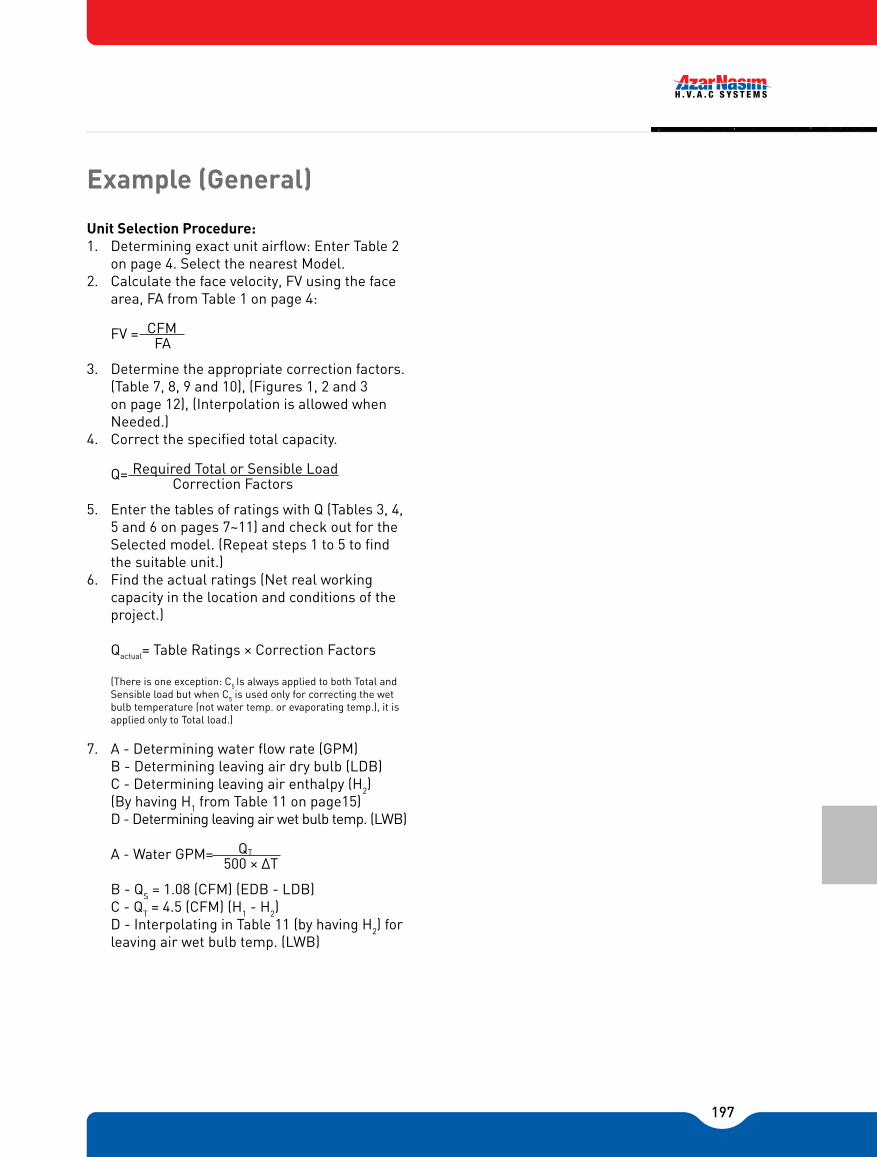
197
Unit Selection Procedure:1. Determining exact unit airflow: Enter Table 2
on page 4. Select the nearest Model.2. Calculate the face velocity, FV using the face
area, FA from Table 1 on page 4:
CFM FV = FA
3. Determine the appropriate correction factors.(Table 7, 8, 9 and 10), (Figures 1, 2 and 3 on page 12), (Interpolation is allowed when Needed.)
4. Correct the specified total capacity.
Required Total or Sensible LoadQ= Correction Factors
5. Enter the tables of ratings with Q (Tables 3, 4, 5 and 6 on pages 7~11) and check out for the Selected model. (Repeat steps 1 to 5 to find the suitable unit.)
6. Find the actual ratings (Net real working capacity in the location and conditions of the project.)
Qactual= Table Ratings × Correction Factors
(There is one exception: C5 Is always applied to both Total and Sensible load but when C5 is used only for correcting the wet bulb temperature (not water temp. or evaporating temp.), it is applied only to Total load.)
7. A - Determining water flow rate (GPM)B - Determining leaving air dry bulb (LDB)C - Determining leaving air enthalpy (H2) (By having H1 from Table 11 on page15)D - Determining leaving air wet bulb temp. (LWB)
Q A - Water GPM= 500 × ΔT
B - QS = 1.08 (CFM) (EDB - LDB)C - QT = 4.5 (CFM) (H1 - H2)D - Interpolating in Table 11 (by having H2) for leaving air wet bulb temp. (LWB)
Example (General)
T

198
Summer System Requirement
Given:Air Flow Rate ����.��.���...���� 1000 CFMExternal Static Pressure ���...��.���...�. 0.3�Total / Sensible Load �...��.�....� 27 /19 kBtu/hrAltitude of Installation .����...........�..�..1250mEntering Air Temperature (EAT) ... 80°F DB/ 70°F WBEvaporating Temperature......................�.. 45/55°F
Solution:1. Table 2 on page 4: Based on airflow, selecting
Model DF 1000: 4 Rows, 8 FPI: Air flow = 1110 CFM
(Selection is based on �Medium� condition in order to account for additional capacity.)
CFM 1110 CFM 2. FV = = = 453 FPM FA 2.45 ft.2
3. Correction factors:(T.7 P.11) Total load correction factor = CT = 1.06(T.7 P.11) Sensible load correction factor = CS= 1.07(T.8 P.11) Altitude correction factor = C2 = 0.95(T.9 P.11) Fin material correction factor = C3 = 1.0(T.10 P.11) Refrigerant correction factor = C4 = 1.0(F.1 P.12) Air wet bulb correction factor = C5 = 1.15
4. Correcting the required load
Total Load 27 KBtu/hr. QT = = = 23.3 kBtu/hr. CT ×C2 ×C5 1.06 × 0.95 × 1.15
Selection Load 19 KBtu/hr.QS = = = 18.7 kBtu/hr. CS × C2 1.07 × 0.95
(For correcting the wet bulb temp. Only. Is applied just to total load.)
5. Entering the table 3 on page 7Model DF 1000: 80°F DB/ 67°F WB, 4 rows, 8 FPI:QT : 26.2 kBtu/hr. > 23.3 kBtu/hr. (required)QS : 21.0 kBtu/hr. > 18.7 kBtu/hr. (required)
So SDF-10 (4 rows, 8FPI, and half Cir.) is approved.
Example 1
6. Actual ratings:Total: QT = 26.2 ×1.06× 1.15 × 0.95 = 30.3 kBtu/hr.Sensible: Qs = 21.0 × 1.07 × 0.95 = 21.3 kBtu/hr.
30300 7. A - Water flow GPM = = 6.1GPM 500 × 10
21300 B - LDB = 80- = 62.2 ˚F 1.08 × 1110
30300 C - H2 = 36.9 - = 30.8 Btu/lb. 4.5 × 1110
D - On Table 11 on pages 15 by H2 andAltitude of 1250m
LWB = 63.1 °F
(Because of the correction factor approximations, the exact temperature sometimes is obtained a little different. The LWB is about 62°F in this case.)

199
Summer System Requirement
Given:Air Flow Rate ����.��.���...���� 1600 CFMExternal Static Pressure ���...��.���...�. 0.2�Total / Sensible Load �...��.�....� 42 /31 kBtu/hrAltitude of Installation .����...........�..�..1250mEntering Air Temperature (EAT) ... 80°F DB/ 67°F WBEvaporating Temperature............................�.. 50°F
Solution:1. Table 2 on page 4: Based on airflow, selecting Model
DF 1200: 4 Rows, 14 FPI: Air flow = 1650 CFM(Selection is based on �Medium� condition in order to account for additional capacity.)
CFM 1650 CFM 2. FV = = = 575 FPM FA 2.87 ft.2
3. Correction factors:(T.7 P.11) Total load correction factor = CT = 1.19(T.7 P.11) Sensible load correction factor = CS = 1.25(T.8 P.11) Altitude correction factor = C2 = 0.95(T.9 P.11) Fin material correction factor = C3 = 1.0(T.10 P.11) Refrigerant correction factor = C4 = 1.0(F.3 P.12) Evaporating Temp. corr. Fac. = C5 = 0.85
4. Correcting the required load
Total Load 27 KBtu/hr. QT = = = 43.7 kBtu/hr. CT × C2 × C5 1.19 × 0.95 × 1.85
Selection Load 31 KBtu/hr.QS = = = 30.7 kBtu/hr. CS × C2 × C5
1.07 × 0.95
5. Entering the table 3 on page 7Model DF 1200: 80°F DB/67°F WB, 4 rows, 14 FPI:QT : 36.0 kBtu/hr. < 43.7 kBtu/hr. (required)QS : 27.3 kBtu/hr. < 30.7 kBtu/hr. (required)So SDF-12 (4 rows, 14FPI and Half Cir. failed.)
Repeating steps 1 to 5:For SDF-12 (6 rows, 8FPI and half Cir.):QT: 37.3 kBtu/hr. < 44.4 kBtu/hr. (required)QS: 28.9 kBtu/hr. > 31.5 kBtu/hr. (required)
So SDF-12 (6 rows, 8FPI and half Cir.) failed.SDF-12 (6 rows, 14FPI and half Cir.) failed.
Example 2
SDF-14 (4 rows, 14FPI and half Cir.) failed.SDF-14 (6 rows, 8FPI and half Cir.) failed.QT : 48.7 kBtu/hr. > 45.2 kBtu/hr. (required)QS : 36.7 kBtu/hr. > 32.3 kBtu/hr. (required)
SDF-14 (6 rows, 14FPI and half Cir.) is approved.
(The actual air flow is 1560 cfm at Medium rotational speed of the fan.)
6. Actual ratings for SDF-14 (6 rows, 14FPI & half Cir.):
QT = 48.7 ×1.15 × 0.85 × 0.95 = 45.2 kBtu/hr.QS = 36.7 ×1.19 × 0.85 × 0.95 = 35.3 kBtu/hr.
45200 7. A - Water flow GPM = = 9.0GPM 500 × 10
35.3 x 1000 B - LDB = 80- = 59.0 ˚F 1.08 × 1560
45.2 x 1000 C - H2 = 34.13 - = 27.7 Btu/lb. 4.5 × 1560
D - On Table 11 by H2 and Altitude of 1250m
LWB = 59.1 °F
(Because of the correction factor approximations, the exact temperature somet imes is obtained a little different. The LWB is about 59°F in this case.)

200
Winter System Requirement (Hot water Coil)
Given:Air Flow Rate ����.��.���...���� 1800 CFMExternal Static Pressure ���...��.���...�. 0.3�Total / Sensible Load �...��.....�....� 160 kBtu/hrAltitude of Installation .����.................�..�..0mEntering Air Temperature (EAT) ..................... 80°F DBEvaporating Temperature...................�.. 180/160°F
Solution:1. Table 2 on page 4: Based on airflow, selecting Model
DF 1600:
4 Rows, 14 FPI: Air flow = 1790 CFM (Selection is based on �Medium� condi t ion in order to account For additional capacity.)
CFM 1650 CFM 2. FV = = = 575 FPM FA 2.87 ft.2
3. Correction factors:
(T.7 P.11) Total load correction factor = CT = 1.07(T.8 P.11) Altitude correction factor = C2 = 1.0(T.9 P.11) Fin material correction factor = C3 = 1.0
4. Correcting the required load
Total Load 160 KBtu/hr QT = = = 149.5 kBtu/hr. CT × C2 × C5 1.07 × 1.0 × 1.0
5. Entering the table 5 on page 10
Model DF 1600: 80°F DB, 4 rows, 14 FPI:QT : 149.8 kBtu/hr. > 149.5 kBtu/hr. (required)
So SDF-16 (4 rows, 14FPI & Half Cir. is approved.6. Actual ratings for SDF-16 (4 rows, 14FPI &
half Cir.):
QT = 149.8 × 1.07 ×1.0 ×1.0 = 160.3 kBtu/hr.
160300 7. A - Water flow GPM = = 16.0GPM 500 × 20
Example 3
160300 B - LDB = 80- = 162.9 ˚F 1.08 × 1790

201
+ Shaded regions show that water velocity or air face velocity is out of standard ARI 410 & 440 limits. (1~8 FPS) (200~800 fpm) 1 2 3 4: Under this condition, if the actual airflow is more than respectively 900, 1300, 2000 and 2200 CFM, then the velocity will be in the range of valid (ARI) Velocities + All the ratings are calculated at altitude 0 (Sea Lev
CHILLED WATER COOLING COIL RATINGS (EWT 45°F, LWT 55°F)
DF 800 80075 63
80 67
DF 1000 100075 63
80 67
DF 1200 1200
75 63
80 67
DF 1400 1400
75 63
80 67
DF 1600 1600
75 63
80 67
DF 1800 1800
75 63
80 67
DF 2000 2000
75 63
80 67
8 FPI
14 FPI
8 FPI
14 FPI
8 FPI
14 FPI
8 FPI
14 FPI
8 FPI
14 FPI
8 FPI
14 FPI
8 FPI
14 FPI
8 FPI
14 FPI
8 FPI
14 FPI
8 FPI
14 FPI
8 FPI
14 FPI
8 FPI
14 FPI
8 FPI
14 FPI
8 FPI
14 FPI
Half
Half
Half
Half
Half
Half
Half
Half
Full
Half
Full
Half
Full
Half
Full
Half
Full
Half
Full
Half
Full
Half
Full
Half
Full
Half
Full
Half
Full
Half
Full
Half
Full
Half
Full
Half
Full
Half
Full
Half
Full
Half
Full
Half
Full
Half
Full
Half
13.917.319.5 1
25.018.0 2
23.026.233.217.822.022.228.923.533.430.242.021.826.527.235.129.140.437.851.225.931.032.341.2
35.14
47.545.460.331.037.338.848.943.756.356.071.336.144.545.956.452.465.366.382.4
13.916.416.319.518.021.021.025.117.821.222.225.722.225.826.531.021.825.027.235.126.430.631.837.025.928.932.335.330.835.537.342.931.034.436.840.836.341.243.849.836.138.642.046.341.947.050.256.6
2.83.53.95.03.64.65.26.63.64.44.45.84.76.76.08.44.45.35.47.05.88.17.610.25.26.26.58.27.09.59.112.16.27.97.89.88.711.311.214.27.28.99.211.310.513.113.216.5
0.250.40.50.70.40.60.81.2
0.080.60.11.00.11.30.22.0
0.10.90.21.50.22.00.33.00.21.30.22.10.32.70.44.50.22.10.43.10.44.00.76.1
0.32.80.54.20.65.51.08.4
19.724.328.934.4
5.5231.537.544.625.331.731.639.136.846.645.155.231.037.838.546.545.155.454.866.1
36.8 3
44.945.554.253.964.665.277.043.852.854.363.564.375.377.289.450.960.762.972.975.185.789.2
101.4
17.119.520.823.621.724.826.630.123.926.527.230.428.632.532.736.828.531.332.535.834.238.339.043.733.136.437.741.440.044.345.650.638.341.943.847.746.551.052.958.143.447.549.854.053.257.660.365.5
4.04.95.86.95.16.37.58.95.16.36.37.87.49.39.0
11.06.27.67.79.39.0
11.111.013.27.49.09.1
10.810.812.913.115.48.8
10.610.912.712.915.115.417.910.212.112.614.615.017.117.820.3
0.60.91.31.71.11.62.12.90.21.70.32.40.43.30.54.50.32.40.43.50.54.80.86.60.43.40.64.80.86.61.19.10.64.90.96.91.29.41.6
12.80.86.81.29.41.6
12.62.2
17.1
Model EnteringDry Bulb
Temp.(°F)
NominalAir CFM
Spacing Circuit 4 Rows 6 Rows
TotalCooling Capacity
(kBtu/hr)
Sensible WaterFlow(GPM)
PressureDrop Ft
H²O
EnteringWet Bulb
Temp.(°F)
Cooling Capacity(kBtu/hr)
Water TotalCooling Capacity
(kBtu/hr)
Sensible WaterFlow(GPM)
PressureDrop Ft
H²O
Cooling Capacity(kBtu/hr)
Water
Table 3

202
DX COIL RATINGS ( 45°F Evaporating Temp.) (Half circuit)
+ All the ratings are calculated at altitude 0 (Sea Level) with Aluminums fins (corrugated plate fins) and based on ARI standard 410.For other Altitudes or Fin Material please refer to Correction Factor Tables.
75 63
80 67
75 63
80 67
75 63
80 67
75 63
80 67
75 63
80 67
75 63
80 67
DF 800 80075 63
80 67
DF 1000 1000
DF 1200 1200
DF 1400 1400
DF 1600 1600
DF 1800 1800
DF 2000 2000
Model EnteringDry Bulb
Temp.(°F)
NominalAir CFM
Spacing 4 Rows 6 Rows
TotalCooling Capacity
(kBtu/hr)
Sensible
EnteringWet Bulb
Temp.(°F)
Cooling Capacity(kBtu/hr)
TotalCooling Capacity
(kBtu/hr)
SensibleCooling Capacity
(kBtu/hr)
Table 4
8 FPI
14 FPI
8 FPI
8 FPI
8 FPI
8 FPI
8 FPI
8 FPI
8 FPI
8 FPI
8 FPI
8 FPI
8 FPI
8 FPI
8 FPI
14 FPI
14 FPI
14 FPI
14 FPI
14 FPI
14 FPI
14 FPI
14 FPI
14 FPI
14 FPI
14 FPI
14 FPI
14 FPI
59.056.260.458.158.155.359.657.356.153.657.755.556.853.958.155.756.153.356.954.455.352.856.353.854.251.755.4
12.915.617.320.616.619.822.526.622.426.530.636.024.729.633.940.329.535.240.548.035.541.948.257.142.950.557.968.5
11.813.914.516.215.618.218.921.020.723.524.827.323.427.128.431.527.731.833.337.032.636.838.742.938.342.845.149.9
61.358.963.361.360.658.162.560.559.056.960.859.059.557.161.259.259.056.660.758.658.256.160.157.957.355.259.156.9
15.919.221.125.020.324.227.132.127.732.937.343.830.937.041.048.736.944.151.060.544.452.360.171.253.663.172.385.6
13.816.316.918.918.221.322.124.524.527.828.931.827.531.933.136.732.637.439.844.238.343.246.050.945.050.353.158.8 52.8
Leaving Air DryBulb Temp.
(°F)
Leaving Air DryBulb Temp.
(°F)

203
+ All the ratings are calculated at altitude 0 (Sea Level) with Aluminum fins (corrugated plate fins) and based on ARI standard 410. + For other Altitudes or Fin Materials please refer to Correction Factor Tables.
HOT WATER COIL RATINGS(same cooling coils with hot water ratings)(EWT 180°F, LWT 160°F)
DF 800 800
DF 1000 1000
50
60
70
80
DF 1200 1200
DF 1400 1400
8 FPI
14 FPI
8 FPI
14 FPI
8 FPI
14 FPI
8 FPI
14 FPI
8 FPI
14 FPI
8 FPI
14 FPI
8 FPI
14 FPI
8 FPI
14 FPI
8 FPI
14 FPI
8 FPI
14 FPI
8 FPI
14 FPI
8 FPI
14 FPI
Model EnteringDry Bulb
Temp.(°F)
NominalAir CFM
Spacing Circuit 4 Rows 6 Rows
TotalHeating Capacity
(kBtu/hr)
WaterFlow(GPM)
PressureDrop Ft
H²O
Water TotalCooling Capacity
(kBtu/hr)
WaterFlow(GPM)
PressureDrop Ft
H²O
Water
Table 5
8 FPI
14 FPI
8 FPI
14 FPI
8 FPI
14 FPI
8 FPI
14 FPI
50
60
70
80
50
60
70
80
50
60
70
80
Leaving Air DryBulb Temp.
(°F)
Leaving Air DryBulb Temp.
(°F)
145.1163.6
146.9164.1148.8164.6
150.6
165.0144.9163.8146.9164.3148.8164.9150.7165.4140.8144.9159.8164.0142.8146.9160.4164.6
144.9148.8160.9165.1146.9150.8161.5
165.7141.2144.9160.4164.1143.3146.9161.0164.7145.3148.9161.6
165.3147.4150.9162.1165.9
8.5
10.27.8
9.37.08.56.37.6
10.6
12.7
9.711.78.8117.99.5
12.212.714.715.311.111.6
13.5
14.010.010.6
12.212.8
9.0
9.5
10.911.5
14.314.817.317.813.013.6
15.816.411.812.314.314.910.5
11.112.813.4
1.48
2.01.31.71.11.5
0.91.22.33.22.0
2.81.7
2.31.41.90.6
3.40.84.70.5
2.90.74.10.4
2.40.6
3.40.3
2.00.5
2.80.84.71.16.6
0.74.00.95.6
0.5
3.40.84.80.4
2.80.6
3.9
97.6108.089.699.481.590.773.482.0121.8135.1111.8124.3101.8113.591.8102.7142.4146.0159.5162.2130.5134.1146.5149.3118.5122.1133.5136.3106.5110.1120.4123.4166.5170.3186.5189.4152.6156.4171.4174.3138.7142.5156.3159.2124.8128.6141.1144.1
162.3174.2163.0174.3163.7174.3164.5
174.3162.1174.3162.9174.4163.7174.4164.4174.5
159.2161.9172.3174.4160.0162.8172.3174.4160.9163.6
172.3174.5
161.7164.4172.3174.6
159.4161.9172.6
174.4160.3162.8172.6
174.5
161.2163.6
172.7174.6
162.0164.5
172.7174.7
10.011.1
9.210.28.4
9.37.6
8.412.5
13.911.5
12.810.5
11.7
9.410.6
14.6
15.016.416.713.413.815.115.312.212.5
13.714.011.011.312.412.717.117.5
19.219.5
15.716.117.6
17.914.314.6
16.116.412.813.214.5
14.8
2.73.32.32.82.0
2.41.6
2.04.35.23.74.5
3.13.82.63.21.06.3
1.27.6
0.95.4
1.16.6
0.74.6
0.95.6
0.63.80.84.71.48.81.7
10.6
1.27.51.5
9.21.06.4
1.37.80.85.31.06.5
Half
Half
Half
Half
Half
Half
Half
Half
Half
Half
Half
Half
Full
Half
Full
Half
Full
Half
Full
Half
Full
Half
Full
Half
Full
Half
Full
Half
Full
Half
Full
Half
Full
Half
Full
Half
Full
Half
Full
Half
Full
Half
Full
Half
Half
Half
Half
Half
82.798.875.690.568.582.261.373.9
103.1123.694.4
113.485.6
103.176.892.8
118.5123.8143.2148.7108.1113.3130.9136.497.6
102.8118.6124.187.292.3
106.3111.8138.8144.4168.0173.7126.7132.2153.7159.4114.6120.1139.4145.1102.5107.9125.0130.7
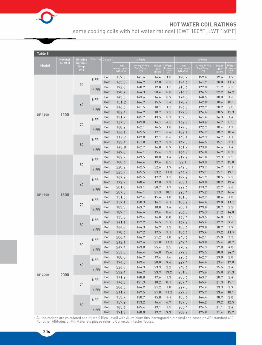
204
HOT WATER COIL RATINGS(same cooling coils with hot water ratings) (EWT 180°F, LWT 160°F)
+ All the ratings are calculated at altitude 0 (Sea Level) with Aluminium fins (corrugated plate fins) and based on ARI standard 410.For other Altitudes or Fin Materials please refer to Correction Factor Tables.
DF 1800 1800
DF 2000 2000
8 FPI
14 FPI
8 FPI
14 FPI
8 FPI
14 FPI
8 FPI
14 FPI
8
8
FPI
FPI
1
1
4
4
F
F
P
P
I
I
8
8
FPI
FPI
1
1
4
4
F
F
P
P
I
I
8
8
FPI
FPI
1
1
4
4
F
F
P
P
I
I
8
8
FPI
FPI
1
1
4
4
F
F
P
P
I
I
Model
EnteringDry Bulb
Temp.(°F)
NominalAir CFM
Spacing Circuit 4 Rows 6 Rows
TotalHeating Capacity
(kBtu/hr)
WaterFlow(GPM)
PressureDrop Ft
H²O
Water TotalCooling Capacity
(kBtu/hr)
WaterFlow(GPM)
PressureDrop Ft
H²O
Water
Table 5
50
60
70
80
50
60
70
80
Leaving Air DryBulb Temp.
(°F)
Leaving Air DryBulb Temp.
(°F)
DF 1600 1200
50
60
70
80
159.3165.0192.8198.7145.5151. 2176.5182.4131.7137.3160.2166.1117.9123.4143. 8149.8182.9188.6220.2225.9167.2172.9201.8207.5151.5157.1183.3189. 1135.8141.1164.8170.6206.4212.1247.4253.0188.8194.5226.8232.4171.2176.8206.5211.9153.7159.2185.6191.3
141.6
144.9160.9164.3143.6146.9161.5
164.9145.7
149.0162.1165.5
147.8151.0162.7166.1
143.5146.4
162.5165.5145.5
148.4163.1166.1
147.4150.3163.7166.6
149.4152.2164.3167.2
144.9147.6
163.8166.4
146.9
149.4164.3166.9148.8151.3164.9167.5
150.7153.2165.4
168.0
16.4
17.019.820.414.615.5
18.118.713.514.116.5
17.1
12.112.714.815.4
18.8
19.422.623.2
17.217.820.721.315.616.1
18.8
19.414.014.5
16.917.5
21.221.825.426.0
19.420.023.323.917.6
18.2
21.221.815.816.4
19.119.7
1.06.31.5
8.80.95.41.27.5
0.74.5
1.06.40.6
3.70.95.31.48.5
1.911.81.27.31.7
10.11.06.11.48.6
0.85.11.27.11.8
11.22.5
15.4
1.6
9.6
2.213.21.38.11.8
11.21.16.71.5
9.3
190.7194.6213.6216.5174.8178.7196.3199.3159.0162.9179.0182.1143.1147.0161.7164.9217.222.1242.0244.7199.2203.1222.6225.4181.3185.2203.1206.0163.4167.2183.6186.6243.6247.4270.2272.9223.6227.4248.6251.3203.6207.4227.0229.8183.6187.3205.4208.2
159.6161.9172.8174.5
160.5162.8
172.9174.6161.4
163.6
172.9174.7162.3164.5
173.0174.8161.0163.0173.7175.1
161.9163.8173.7175.2162.7164.6
173.8175.3163.5165.4
173.8175.4
162.1163.8174.3175.5
162.9164.6
174.4175.6
163.7165.4
174.4175.7164.4
166.2174.5
175.8
19.620.0
21.922.218.018.420.220.516.316.7
18.418.714.715.116.6
16.922.3
22.724.925.120.520.9
22.923.218.619.020.9
21.216.8
17.218.919.225.025.427.828.023.023.425.525.820.921.323.323.618.9
19.221.121.4
1.911.7
2.3
14.21.6
10.1
2.012.31.48.5
1.710.41.17.11.48.7
2.5
15.83.1
19.12.2
13.6
2.616.4
1.811.5
2.214.01.5
9.6
1.911.73.3
20.74.0
24.72.8
17.83.4
21.3
2.415.1
2.918.1
2.012.5
2.415.2
Half
Half
Half
Half
Full
Half
Full
Half
Full
Half
Full
Half
Full
Half
Full
Half
Full
Half
Full
Half
Full
Half
Full
Half
Full
Half
Full
Half
Full
Half
Full
Half
Full
Half
Full
Half
Full
Half
Full
Half
Full
Half
Full
Half
Full
Full
Full
Full

205
DF 800
DF 1000
DF 1200
DF 1400
DF 1600
DF 1800
DF 2000
Total
Sensible
300 350 375 400 425 450 475 500 525 550 600 650
0.82 0.94 0.98 1.01 1.05 1.08 1.12 1.15 1.18 1.20 1.26 1.32
0.83 0.92 0.97 1.01 1.05 1.10 1.15 1.19 1.23 1.27 1.34 1.42
0.83 0.92 0.96 0.99 1.03 1.06 1.09 1.13 1.16 1.19 1.24 1.30
0.80 0.90 0.94 0.99 1.04 1.07 1.12 1.16 1.20 1.23 1.31 1.38
0.81 0.90 0.93 0.97 1.01 1.04 1.07 1.10 1.13 1.16 1.22 1.28
0.78 0.88 0.92 0.97 1.01 1.05 1.09 1.13 1.17 1.21 1.28 1.35
0.80 0.88 0.92 0.96 1.00 1.03 1.06 1.09 1.13 1.16 1.22 1.27
0.77 0.87 0.91 0.96 1.00 1.04 1.08 1.12 1.16 1.20 1.26 1.33
0.79 0.88 0.91 0.95 0.99 1.03 1.06 1.09 1.12 1.15 1.21 1.27
0.77 0.86 0.90 0.94 0.99 1.03 1.07 1.10 1.14 1.18 1.25 1.32
0.81 0.90 0.94 0.98 1.01 1.05 1.09 1.12 1.16 1.18 1.25 1.30
0.79 0.88 0.93 0.97 1.01 1.06 1.10 1.14 1.18 1.21 1.29 1.36
0.82 0.91 0.95 0.99 1.04 1.07 1.11 1.14 1.17 1.21 1.27 1.33
0.80 0.90 0.94 0.99 1.02 1.08 1.12 1.16 1.20 1.24 1.31 1.39
Model
Table 7 COIL FACE VELOCITY CORRECTION FACTOR
Correctiontype
Face Velocity (FPM)
Total
Total
Total
Total
Total
Total
Sensible
Sensible
Sensible
Sensible
Sensible
Sensible
* air temperature leaving the electrical coil = entering air temperature (before the coil) + ΔT (5 / 10 / 20 °F+ Azar Nasim does not provide any control device for electrical heater except air flow switch.
Use these correction factors as multipliers to the capacity ratings offered in the tables.
Real TableCapacity = Ratings ×C1×C2×C3×C4×C5KBtu/hr. KBtu/hr.
Table Ratings: Capacity from Tables 3 ~ 6 (pages 7~11)C1: (CTor CS) Coil Face Velocity Correction Factor from Table 7 (page 11)C2: (CA) Altitude Correction Factor from Table 8 (page 11)C3: Fin Material Correction Factor from Table 9 (page 11)C4: Refrigerant Correction Factor from Table 10 (page 11)C5: (CWB) Air Wet Bulb or Entering Water or Evaporating FACTOR ( C3 ) Temperature Correction Factor from figures 1~3 (page 12) or+ Divide your required capacity by these correction factors before you go through the tables.
1.5 1 7 1 3.0 1 14 2 2×1.5 5.5 1 25 3
1.5 7 1 3.0 1 14 2 7.0 1 32 3
2.0 9 1 4.0 1 18 2 2+2 8.0 1 36 3
2.0 9 1 1×2 5.0 1 23 2 2+3 9.0 1/3 41/24 3
3.0 14 2 5.0 1 23 2 2+3 10.5 1 48 3
3.0 14 2 6.0 1/3 27/16 3 3×2 12.0 1/3 55/32 3
3.0 14 2 7.0 1 32 3 2+2+3 13.5 1 61 3
DF 800 800
DF 1000
DF 1200
DF 1400
DF 1600
DF 1800
DF 2000
Model
Table 6 ELECTRICAL COIL
NominalAir CFM
1000
1200
1400
1600
1800
2000
Air Temperature Rise* (T)
5°F 10°F 20°FHeatingCapacity
(kW) Phas
e LineCurr.
(Amp.)
No. ofContr.Steps
No. andCap. (kw)of Elem.
Heating HeatingCapacity Capacity
(kW) (kW)Phas
e
Phas
eLine LineCurr. Curr.
(Amp.) (Amp.)
No. of No. ofContr. Contr.Steps Steps
No. and No. andCap. (kw) Cap. (kw)of Elem. of Elem.
2+2+1.5
3+2+2
3+3+2
3×3
3×3+1.5
3×4
3×4+1.5
2×1.5
2×1.5
2×1.5
2×1.5
1×2
1×1.5
1×1.51
1
1
1
1
1
R22 1
R134a 0.88
R407c 0.99
Al 1
Cu 1.05
0 0 1
2500 760 0.97
5000 1500 0.94
7500 2300 0.91
10000 3050 0.88
ALTITUDE CORRCTION FACTOR (C2)
ft
Table 8
Capacity Factorm
Table 9 FIN MATERIAL CORRECTION FACTOR (C3)
Fin Material Correction Factor
Table 10 REFRIGERANT CORRECTION FACTOR (C4)
Refrigerant (Dx Coil) Correction Factor

206
FIGURE 1. CHILLED WATER COIL
ENTERING WATER TEMP. °F ENTERING AIR TEMP. °F ENTERING WET BULB TEMP. °F
CAPA
CIT
Y C
OR
REC
TIO
N F
ACT
OR
CAPA
CIT
Y C
OR
REC
TIO
N F
ACT
OR
CAPA
CIT
Y C
OR
REC
TIO
N F
ACT
OR
CONTROL FEATURESThere are different ways of controlling fan coils:
FIGURE 2. HOT WATER COIL
FIGURE 3. DX COIL
CORRECTION FACTOR CORRECTION FACTOR CORRECTION FACTOR Corrected load = load from table 3*correction factor from figure 1 All correction factors are Based on 80/67°F entering dry and wet bulb temp.
1. Fan Speed Control a) Manual >The units are provided with a manual three- fan speed control. (Unit or wall mounted)
2. Water Control Valves a) Manual >By having hand-operated valves installed in the supply or return water circuit, each unit could be isolated from the whole water system. (Not included)
B - AutomaticThe fans could be switched ON/OFF while has been set to one of the three different working condition (Low, Medium or High) by a single-stage thermostat. (Not included) A Four-stage thermostat (including OFF) could also control the fan speed automatically. (Not included)
Corrected load = load from table 5*correction factor from figure 2 All correction factors are based on entering air dry bulb = 60°F and entering water = 180°F
Corrected load = load from table 4*correction factor from figure 3 All correction factors are based on 80/67 Entering dry and wet bulb temp. at 45°F Evaporating temp.
B - AutomaticValves could be either solenoid or motor operated. Two or Three way valves also could be used.(Not included) Thermostat could control a solenoid valve or also two-way or Three-way water Valve to set the suitable flow rate of water. (Not included)
3. Electrical Coil Safety Temperature ControlAn optional control device could turn off the electrical coil if its temperature rises above a defined limit.(Not included)
2.22.1
2.0
1.9
1.8
1.7
1.6
1.5
1.4
1.3
1.2
1.1
1.0
0.9
0.8
0.7
0.5
0.4
0.3
0.2
0.10.0
0.6
35° 40° 45° 50° 55°
ENTERING AIR 83° WB79° WB75° WB71° WB67° WB63° WB
59° WB
ENTERING WATER TEMP 180°
170°
160°
150°
140°
130°
120°
1.101.05
1.00
0.95
0.90
0.85
0.80
0.80
0.75
0.70
0.65
0.60
0.55
0.50
0.45
0.40
0.35
0.30
0.25
0.20
0.15
0.10
0.050.00
55° 60° 65° 70°50° 75° 80°
40°
F EV
APOR
ATIN
GTE
MP.
45°
F EV
APOR
ATIN
GTE
MP.
50°
FEV
APOR
ATIN
GTE
MP.
2.0
1.5
1.0
0.560° 70° 80° 90°
CAPACITY CORRECTION FACTOR

207
*supply Duct Collar Is Bx270 For All Horizontal Models.
1 650 285 500
1� 1� 3/4"
67 70
1 750 345 600 72 75
1 950 750 700 96 90
2 950 750 800 96 100
2 1050 805 900 103 105
2 1200 870 1050 112 118
2 1350 960 1200 120 127
DF 800 800
DF 1000
DF 1200
DF 1400
DF 1600
DF 1800
DF 2000
Model
Figure 6 EXPOSED VERTICAL FREE STANDING MODELS
NominalAir CFM
1000
1200
1400
1600
1800
2000
Numberof Fans
A B C Inlet Outlet DrainUnit Weight (kg)
Oper. Net
FIGURE 4. EXPOSED HORIZENTAL MODELS
FIGURE 5. CONCEALED HORIZENTAL MODELS
*All dimensions in mm except as specified *All dimensions ± 5 mm *All dimensions are subject to change without notice
1. MOUNTING BRACKET2. MOTOR JUNCTION BOX3. FOAM INSULATION4. DRAIN CONNECTION5. SUPPLY DUCT COLLAR6. AIR VENT7. FILTER (OPTIONAL)8. MOUNTING LEGS (OPTIONAL)9. RETURN DUCT COLLAR 10. DRAIN PAN11. COIL WATER INLET12. COIL WATER OUTLET
40
45
�34
85
B
270
1 1
5
211
12
4
A
1540
35
50C 130
225
1540
40
6
11
12
104
3
1
SUPPLY AIR
FILTER REMOVAL
380
A
B5
2
6
11
12
4
8
SUPPLY AIR
2
3
5
6
7
430270
900
80 160
100
410
9
10
11
12
3 4
RET
UR
N A
IR
SUP
PLY
AIR
1
1
3 4
5
6
79
10
11
12
430 27
0
225
100
650900
370
100
635
170
365
35
40
255
390
SUP
PLY
AIR
RET
UR
N A
IR
1
3
4
5
6
10
11
12
*supply Duct Collar Is Cx365 For All Concealed Horizontal Models.
*supply Duct Collar Is Bx270 For All Vertical Models.

208
* The frame above is not included with units.* All dimensions are in mm.* The units are fastened to the Rawl bolts.* The square metal plates in the end of hanger will be
placed inside concrete before concrete pouring.* M for Exposed Horizontal models is equal to A in
dimension tables on page 13 and for Concealed* Hori2ontal models is equal to C on the same page.* N for Exposed Horizontal models is 650 mm and for* Concealed Horizontal models is 155 mm.* X should be determined according to ceiling dimentions.* The thickness of metal angles (profiles) is at least 2 mm.* 4 fastening rods for each unit are required.
* Using of springs to avoid transmission of vibration to the building is strongly recommended.
* For each spring it is recommended that k = 9 N/mm* Various types of springs could have a k of 9 N/mm. A
common example could be as in the figure
FLEXIBLE CONNECTION(BY OTHERS)
FASTENING ROD(RAWL BOLT) (SEE DETAIL A)
FRESH AIR DAMPER(OPTIONAL)
RETURN AIRSUPPLY AIR
FALSE CEILING ACCESS DOOR(BY OTHERS)
RETURN AIR
FALSE CEILING ACCESS DOOR(BY OTHERS)
RETURN AIR
SUPPLY AIR
FRES
H A
IR
FASTENING ROD(RAWL BOLT)
FLEXIBLE CONNECTION(BY OTHERS)
FRES
H A
IR G
RIL
L W
ITH
FIL
TER
(BY
OTH
ERS)
X
MN
150
40
150
40
RAWL BOLT
RAWL BOLT
RUBBER CUSHION
M10
FASTENING SLOT
A. FOR CONCRETE CEILING OR HOLLOW CONCRETE BLOCKS
SUSPENDED FASTENING DETAILS DETAIL A
RAWL BOLT
RUBBER CUSHION
M10
FASTENING SLOT
SPRING
A. FOR CONCRETE CEILING OR HOLLOW CONCRETE BLOCKS
SUSPENDED FASTENING DETAILS DETAIL A
SPRING
55 40 23
25 100150
80.1°12
20
20
ø10
40
200
3
20mm
16mm
56mm d= 2mmd: springwirediameter
number of coil= 3(withoutdeginningand ending)
INSTALLATION

209
Table 11 AIR ENTHALPY vs. ALTITUDE
WetBulb
Temp.°F
Altitude
Enthalpy of Air (Btu/lb.)
0 1000 (ft.) 2000 (ft.) 3000 (ft.) 4000 (ft.) 5000 (ft.)
315 (m)0 625 (m) 940 (m) 1250 (m) 1560 (m)
35 3637383940414243444546474849505152535455565758596061626364656667686970717273747576777879808182838485
13.0113.4413.8714.3214.7715.2315.716.1716.6617.1517.6518.1618.6819.2119.7520.3020.8621.4422.0222.6223.2223.8424.4825.1225.7826.4627.1527.8528.5729.3130.0630.8331.6232.4233.2534.0934.9535.8336.7437.6638.6139.5740.5741.5842.6243.6944.7845.947.0448.2249.43
13.1813.6214.0614.5114.9715.4415.9216.4216.8917.3917.9118.4318.9619.520.0520.6121.1921.7722.3722.9823.624.2424.8825.5526.2226.9227.6228.3429.0829.8430.6131.432.2133.0333.8834.7435.6336.5437.4638.4239.3940.3941.4142.4543.5344.6245.7546.9148.0949.350.33
13.3613.814.2514.7115.1815.6616.1416.6417.1417.6518.1718.719.2519.820.3620.9421.5222.1222.7323.3623.9924.6425.3125.9926.6827.3928.1128.8529.6130.3931.1831.9932.8233.6734.5435.4336.3437.2738.2339.240.2141.2342.2943.3644.4745.646.7647.9549.1850.4351.71
13.5414
14.4614.9215.415.8916.3816.8817.3917.9218.4518.9919.5520.1120.6921.2721.8722.4923.1123.7524.425.0725.7526.4427.1527.8828.6229.3930.1630.9631.7732.6133.4634.3335.3236.1437.0838.0439.0240.0341.0642.1243.2144.32
45.4646.6347.8349.0550.3251.6152.94
13.7414.2014.6715.1415.6316.1216.6317.1417.6618.2018.7419.2919.8620.4421.0321.6322.2422.8723.5124.1624.8325.5126.2126.9227.6528.4029.1629.9430.7431.5632.3933.2534.1335.0335.9536.8937.8538.8439.8640.8941.9643.0544.1745.3246.4947.7048.9450.2151.5152.8554.22
13.9414.4114.8915.3715.8716.3716.8917.4117.9418.4919.0419.6120.1920.7821.3822.0022.6223.2723.9224.5925.2825.9826.6927.4228.1728.9429.7230.5231.3532.1933.0533.9334.8335.7536.7037.6738.6739.6940.7341.8042.9044.0245.1846.3647.5848.8350.1051.4252.7654.1555.57
050010001500200025003000350040004500500055006000650070007500800085009000950010000
0(160)(310)(460)(610)(770)(920)(1070)(1220)(1380)(1530)(1680)(1830)(1990)(2140)(2290)(2440)(2600)(2750)(2900)(3050)
0.07500.07390.07280.07180.07070.06970.06860.06760.06660.06560.06460.06370.06270.06170.06080.05990.05900.05800.05710.05630.0554
29.9229.3828.8528.3327.8227.3126.8226.3225.8425.3624.9024.4323.9823.5323.0922.6522.2221.8021.3920.9820.58
Table 12 AIR DENSITY vs. ALTITUDE
Altitude Feet (meters)Density Press.
lb./ft.3 in. w.g

210
211
212

213
UNIT HEATERS

214
Fireproof electro motors (anti friction)For dangerous places, elector motors with Exd certificate , Zonel, A11, B11 and heat temperature of class T4 is supplied. Velocity of existing electro motors is 1400 RPM which are wire wrapped as single phase or three phases.
Air damper:Dampers are manually adjustable in which every blade is regulated singly and installed in outlet of unit heater. For hothouse unit heaters no damper is installed and standing industrial units� dampers are according to Italian ARISIO brand.
Classification of unit heaters:1. General Industrial Unit Heaters2. Standing Industrial Unit Heater3. Hot house Unit Heaters (special for high
temperatures above 60 centigrade)
UNIT HEATER
INTRODUCTION
This catalogue consists comprehensive information of unit heaters manufactured by Tahvieh Azar Nasim Company. Unit heaters of this company are designed for provision of warm air for industries, sport salons, store houses, pools and other similar places and heating fluid of these unit heaters is pumped hot water or water steam system. This system is usually installed above the ground level and air outlet is in horizontal or vertical position.
Main elements details:Main structure of each unit heater consists of aluminum or steel body or fiberglass decorative body, heating coil made of copper or steel pipes and aluminum fins, air outlet damper has adjustable single blades and propeller fan and electromotor, axial fan and related guard, four hanging plates according air outlet position (horizontal or vertical) for installation of unit heaters at the place.
Body:The body is made of steel sheet with appropriate thickness together with one layer of baked furnace color; body of the decorative is made of fiberglass and aluminum body with aluminum sheets without color in different sizes and dimensions.
Coils:Water coils are made of copper pipes and water steam coils are made of seamless steel pipes. Standard fins of both coils are made of aluminum fins. Copper fins may be made upon request. Electrical coil may replace water or steam coils as well.
Fan electromotor:Electromotor of unit heaters are single velocity. ordinary electro motors are supplied with low velocity or any velocity according to order of he customer. Single phase and three phase motors both may be supplied upon request of the customer.(for industrial, hothouse units centrifugal fans are used with static and dynamic balance.)

215
All the three types may be designed and produced using hot water, steam, hot oil coils and electrical coils.
<Note: for this special case antistatic blade fans are supplied.

216
General Industrial Unit Heaters
Note: All Dimensions in mm
GFEDCBAHWL
3/41116500270041010080120300500350500
1118800300041010080120300500350500
1119100320041010080120390580350580
11112000400041010080120390580350580
11 1/41 1/41 1/413000400041010080120460660350660
11 1/41 1/41 1/414000400041010080120540750350750
11 1/41 1/41 1/414500450041010080120540750350750
11 1/41 1/41 1/415000450041010080120610810350810
11 1/41 1/41 1/416000450041010080120650850350850
TU 40w-60S
TU 50w-75S
TU 70w-115S
TU 80w-140S
TU 120w-160S
TU 150w-230S
TU 180w-280S
TU 200w-300S
TU 250w-400S
Model
Figure 1
Water (Inch) Steam (Inch)
In Out In Out
3/4
3/4
3/4
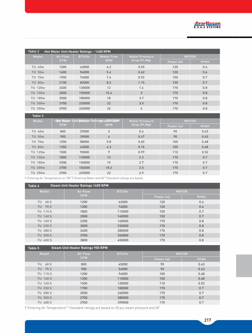
217
F Entering Air Temperature on 180˚F Entering Water and 60˚*Standard ratings are based.
F Entering Air Temperature˚* Standard ratings are based on 30 psi steam pressure and 60˚
0.61200.554.2420001300
0.61200.625.41400
0.71500.927.4740001900
0.71501.158.2820002100
0.81701.4121200002400
0.8170315.41550003000
0.83.7181800003500
0.81703.5222200003700
0.81704262600003900
TU 40w
TU 50w
TU 70w
TU 80w
TU 120w
TU 150w
TU 180w
TU 200w
TU 250w
Model
Table
Drop (Ft.Wg)MOTORWater Pressure Water Flow
GPMBTU/hr.Air Flow
CFM AmpsPower (w)
170
54000
0.43900.4329000800
0.43900.47439000900
0.481000.655.8580001250
0.481000.766.3630001350
0.521100.999900001500
0.71702.2121200001800
0.71702.7151500002500
0.71702.518.21820002700
0.71702.9222200002900
TU 40w
TU 50w
TU 70w
TU 80w
TU 120w
TU 150w
TU 180w
TU 200w
TU 250w
Model
Table 3
Drop (Ft.Wg)MOTORWater Pressure Water Flow
GPMBTU/hr.Air Flow
CFM AmpsPower (w)
Model MOTORBTU/hr.
AmpsPower (w)
Air Flow CFM
0.6120620001200TU 60 S0.6120740001300TU 75 S0.71501150001800TU 115 S0.71501400002000TU 140 S0.81701600002200TU 160 S0.81702300003000TU 230 S0.81702800003400TU 280 S0.81703400003700TU 300 S0.81704500003800TU 400 S
Table ea eae a
Model MOTORBTU/hr.
AmpsPower (w)
Air Flow CFM
0.439045000800TU 60 S0.439054000900TU 75 S0.48100940001200TU 115 S0.481001100001350TU 140 S0.521101300001500TU 160 S0.71701800001700TU 230 S0.71702400002500TU 280 S0.71702800002700TU 300 S0.71703900002900TU 400 S
Table ea eae a
-Hot Water Unit Heater Ratings � 900 RPM
-Hot Water Unit Heater Ratings � 1400 RPM

218
-10
1.155
0
1.130
10
1.105
20
1.082
30
1.060
40
1.040
50
1.020
60
1.000
70
0.982
80
0.964
90
0.945
100
0.930
Table 6 CFM Correction Factors Data
30
40
50
60
70
80
90
100
150
1.035
0.940
0.840
0.743
0.650
0.570
0.475
0.395
160
1.115
1.025
0.930
0.835
0.745
0.650
0.565
0.475
170
1.210
1.105
1.050
0.920
0.825
0.735
0.640
0.560
180
1.295
1.195
1.090
1.000
0.905
0.815
0.720
0.710
190
1.380
1.275
1.175
1.080
0.980
0.895
0.805
0.790
200
1.465
1.360
1.265
1.165
1.070
0.980
0.885
0.875
210
1.545
1.440
1.345
1.240
1.150
1.060
0.965
0.955
220
1.640
1.535
1.430
1.325
1.235
1.140
1.050
1.035
230
1.720
1.620
1.510
1.405
1.315
1.220
1.130
1.115
240
1.810
1.700
1.600
1.500
1.392
1.300
1.210
1.165
250
1.895
1.785
1.690
1.580
1.480
1.380
1.280
1.185
Table 7
Entering Air Temp. °F
Hot Water Correction Factors
0 2 5 10 15 20 30 40 50 60 80 100 125 150 175
-30
-20
-10
0
10
20
30
40
1.133
1.082
1.036
0.989
0.942
0.894
0.849
0.802
1.163
1.113
1.066
1.020
0.973
0.926
0.880
0.883
1.200
1.153
1.107
1.060
1.013
0.967
0.920
0.873
1.258
1.211
1.164
1.117
1.071
1.024
0.977
0.930
1.308
1.258
1.212
1.166
1.118
1.073
1.026
0.978
1.348
1.301
1.254
1.207
1.161
1.114
1.067
1.021
1.420
1.373
1.325
1.278
1.233
1.186
1.139
1.092
1.482
1.431
1.384
1.338
1.292
1.244
1.198
1.151
1.532
1.483
1.436
1.386
1.342
1.296
1.250
1.202
1.585
1.528
1.481
1.434
1.388
1.341
1.294
1.248
1.654
1.605
1.558
1.512
1.465
1.418
1.372
1.325
1.717
1.670
1.623
1.576
1.530
1.483
1.436
1.390
1.792
1.740
1.693
1.647
1.601
1.553
1.506
1.461
1.847
1.801
1.755
1.708
1.660
1.615
1.568
1.521
1.903
1.855
1.808
1.762
1.715
1.669
1.622
1.575
45
50
55
60
65
70
75
80
0.779
0.756
0.732
0.709
0.686
0.662
0.639
0.616
0.810
0.786
0.763
0.740
0.716
0.693
0.670
0.646
0.850
0.827
0.803
0.780
0.757
0.733
0.710
0.687
0.907
0.884
0.861
0.837
0.814
0.791
0.767
0.744
0.955
0.932
0.908
0.885
0.862
0.838
0.815
0.792
0.997
0.974
0.951
0.927
0.904
0.881
0.857
0.934
1.069
1.045
1.023
1.000
0.976
0.935
0.939
0.906
1.128
1.104
1.081
1.058
1.034
1.011
0.988
0.865
1.180
1.156
1.133
1.109
1.086
1.063
1.040
1.016
1.224
1.201
1.178
1.154
1.131
1.108
1.084
1.061
1.302
1.273
1.255
1.231
1.209
1.186
1.163
1.139
1.366
1.343
1.320
1.297
1.273
1.250
1.226
1.203
1.436
1.414
1.390
1.367
1.343
1.320
1.297
1.273
1.496
1.474
1.451
1.427
1.407
1.380
1.357
1.335
1.552
1.529
1.505
1.482
1.459
1.435
1.412
1.389
85
200
90
100
110
120
140
160
180
0.592
0.056
0.562
0.522
0.476
0.429
0.336
0.242
0.149
0.623
0.085
0.600
0.533
0.506
0.460
0.366
0.273
0.179
0.663
0.127
0.640
0.593
0.547
0.500
0.407
0.313
0.220
0.720
0.183
0.696
0.650
0.603
0.556
0.464
0.370
0.227
0.768
0.232
0.745
0.698
0.652
0.605
0.512
0.418
0.325
0.811
0.274
0.787
0.732
0.694
0.647
0.554
0.460
0.367
0.883
0.345
0.860
0.813
0.766
0.720
0.626
0.533
0.439
0.941
0.405
0.918
0.871
0.825
0.778
0.685
0.591
0.498
1.993
0.455
0.969
0.923
0.876
0.830
0.737
0.642
0.550
1.038
0.501
1.014
0.968
0.921
0.874
0.781
0.688
0.594
1.116
0.577
1.093
1.045
0.998
0.952
0.858
0.765
0.671
1.180
0.643
1.156
1.110
1.063
1.027
0.923
0.831
0.737
1.251
0.713
1.226
1.181
1.134
1.086
0.993
0.901
0.808
1.310
0.775
1.288
1.240
1.194
1.147
1.055
0.961
0.868
1.365
0.775
1.342
1.295
1.248
1.201
1.108
1.012
0.921
200
1.956
1.903
1.856
1.810
1.764
1.717
1.670
1.628
1.601
1.576
1.553
1.531
1.506
1.484
1.460
1.436
1.414
0.876
1.390
1.344
1.297
1.251
1.156
1.065
0.970
Table 8
Entering Air Temp. °F
Steam Correction Factors
0
212.00
970.40
2
218.47
966.20
3
221.50
964.27
5
227.16
960.54
8
234.78
955.58
10
239.41
952.49
15
249.73
945.49
20
258.85
939.26
25
266.85
933.63
30
274.64
923.77
35
280.64
923.77
40
286.74
919.14
45
292.37
915.14
50
297.70
911.24
60
307.30
903.91
Table 9Pressure (psi)
Temperature °F
Latent Heat Btu/Lb
70
316.03
897.28
75
320.00
894.20
80
323.89
8891.20
90
331.16
885.42
100
337.86
880.82
110
344.22
874.85
120
350.09
870.05
125
353.00
867.70
130
355.65
865.48
140
360.89
861.12
150
365.92
856.92
175
377.47
847.02
200
387.88
838.00
225
397.27
828.30
250
406.01
820.00
Cont. Table 9Pressure (psi)
Temperature °F
Latent Heat Btu/Lb

219
PIPING
As the function of a unit heater is to transfer heat from steam or hot water to the surrounding Area. It´s necessary that the steam or hot water be delivered to the unit and removed from it In required quantity and condition.
The piping of the unit heaters must conform strictly to the system requirements, while at the same intended. The following are a few piping guidelines which must be observed when Designing piping system for unit heaters.
1. Steam and condensate lines in steam unit, must be sized for maximum load condition. This rule must be observed in hot water units, too. The maximum pressure loss in hot water Piping is 1m H2o per 30 m equal length of piping.
2. In steam unit heaters installation, the supply line should be pitched towards the main line In order to prevent of condensate flow into main line where it might reduce capacity and Cause noise, in hot water unit heaters both supply and return lines should be paralleled towards the unit.
3. The return line in steam unit heaters must be installed at minimum 300 mm below the unit, This prevents accumulation of condensate water in the return line, check valve, strainers and Traps. It also increases life time of this parts and will improve unit operation.
4. By using a steam trap in return line can improve heating capacity certainly. The trap size Must be proportionate to unit capacity, otherwise, the condensate water will accumulate in The unit or steam will eject from return line.
5. Dirt trap in return line, prevent entrance of dirt and scales in to the pipe line. Furthermore, by cleaning the dirt trap cartridge, you can throw away all scales and dirt from inside the Pipe line.
6. By connecting an air vent (at least 3/4") on top of the return line, can dearate piping system, periodically.
7. In order to improve the efficiency of system, it's necessary to insulate all pipe lines witch Are in contact with cold air in winter.
8. Steam piping and unit heaters should be supported independently.

220
Model
Table 10
TU 40w -60s
TU 50w -75s
TU 70w -115s
TU 80w -140s
TU 120w -160s
TU 150w -230s
TU 180w -280s
TU 200w -300s
TU 250w -400s
Sitting Bracket Dimensions
CBA(mm)
SW
3225380540800
3427385540800
3831385620800
4033385620800
4538385700800
5245385795800
5546385795800
6052385850800
6760385890800
Weight (kg)(mm) (mm)
GATE VALVE (SHUT OFF)
STEAM MAIN
CONDENSATEUNION
DRAIN POCKETSTRAINER
STEAM TRAP
SWING CHECK VALVE
STEAM HEATING SYSTEMS
AIR VENT
GATE VALVE (SHUT OFF)
HWR
UNIONBALL VALVE (BALANCING)
DRAIN VALVE
HWS
HOT WATER SYSTEMS

221
EDCBAWL
4001000
CoilWidth
100
150
180
No. ofRows
1
2
3
60300700TU 50 -85 W - S
750TU 65 -90 W - S
1100800TU 70 -120 W - S
80850TU 75 -125 W - S
11501000TU 90 -140 W - S
1000TU 90 -170 W - S
1001100TU 100 -170 W - S
5001200400TU 100 -185 W - S
120TU 100 -200 W - S
1150TU 100 -220 W - S
Model
Table 11 Dimensions
1100
1100
1100
300
300
300
300
300
300
400
400
60
60
80
80
100
120
1000
1100
1150
1150
1200
400
400
400
400
400
400
500
400
950
1000
1300
1350
1500
1800
180
1950
2100
2300
Standing Industrial Unit Heater
Note: All Dimensions in mm

222
Standing Industrial Hot Water Unit Heater Ratings 2 Rows coil
TU 50 85 W
TU 65-90 W
TU 70-120 W
TU 75-125 W
TU 90-140 W
TU 90-170 W
TU 100-170 W
TU 100-185 W
TU 100-200 W
TU 100-220 W
Model
Table 12
MOTOR Water Flow GPM
BTU/hr.Air Flow CFM AmpsPower (w)
RPM Fan Size
2000
2500
3000
3500
3000
3250
3900
4000
3800
4500
5250
5400
4000
4600
5000
6000
6500
7000
7800
8400
8000
8500
9000
10200
8900
9500
10500
11400
9300
10600
11000
12600
10000
11000
12000
13200
11600
12500
13800
15000
0.5
0.75
0.75
0.75
0.75
0.75
1
1
1
1.5
1.5
1.5
1.5
1.5
2
2
1.5
1.5
2
2
1.5
2
2
2
2
2
3
3
3
4
4
4
4
5.5
5.5
5.5
2x3
2x3
2x4
2x4
0.78
1.18
1.18
1.18
1.18
1.18
1.5
1.5
1.5
2.3
2.3
2.3
2.3
2.3
3.15
3.15
2.3
2.3
3.15
3.15
2.3
3.15
3.15
3.15
3.15
3.15
4.7
4.7
4.7
6.3
6.3
6.3
6.3
8.6
8.6
8.6
2x4.7
2x4.7
2x6.3
2x6.3
199000
248400
298000
348000
299000
322920
387504
397440
378000
448000
522000
537000
398000
457000
496800
597000
646000
695500
775000
835000
795000
844500
895000
1000000
885000
944000
1045000
1130000
925000
1050000
1095000
1250000
994000
1092000
1192000
1310000
1152000
1242000
1371000
1490500
20
25
30
35
30
33
39
40
38
45
53
54
40
46
50
60
65
70
78
84
80
85
90
100
89
95
105
114
93
105
109
125
100
110
120
131
116
125
138
150
596
620
657
705
545
566
615
640
590
620
686
705
615
640
686
710
650
690
705
757
528
551
595
604
507
530
551
640
420
460
482
530
420
439
482
528
469
486
507
528
2�19
1�22
1�22
1�19
1�19
1�16
1�16
1�14
1�14
1�14

223
Standing Industrial Hot Water Unit Heater Ratings3 Rows coil
*Standard Entering Hot water 180˚F
TU 50 85 W
TU 65-90 W
TU 70-120 W
TU 75-125 W
TU 90-140 W
TU 90-170 W
TU 100-170 W
TU 100-185 W
TU 100-200 W
TU 100-220 W
Model
Table 13
MOTOR Water Flow GPM
BTU/hr.Air Flow CFM AmpsPower (w)
RPM Fan Size
2000
2500
3000
3500
3000
3250
3900
4000
3800
4500
5250
5400
4000
4600
5000
6000
6500
7000
7800
8400
8000
8500
9000
10200
8900
9500
10500
11400
9300
10600
11000
12600
10000
11000
12000
13200
11600
12500
13800
15000
0.5
0.75
0.75
0.75
0.75
0.75
1
1
1
1.5
1.5
1.5
1.5
1.5
2
2
1.5
1.5
2
2
1.5
2
2
2
2
2
3
3
3
4
4
4
4
5.5
5.5
5.5
2x3
2x3
2x4
2x4
0.78
1.18
1.18
1.18
1.18
1.18
1.5
1.5
1.5
2.3
2.3
2.3
2.3
2.3
3.15
3.15
2.3
2.3
3.15
3.15
2.3
3.15
3.15
3.15
3.15
3.15
4.7
4.7
4.7
6.3
6.3
6.3
6.3
8.6
8.6
8.6
2x4.7
2x4.7
2x6.3
2x6.3
596
620
657
705
545
566
615
640
590
620
686
705
615
640
686
710
650
690
705
757
528
551
595
604
507
530
551
640
420
460
482
530
420
439
482
528
469
486
507
528
2�19
1�22
1�22
1�19
1�19
1�16
1�16
1�14
1�14
1�14
238000
297000
356000
416000
356000
386000
464000
475000
451000
534600
624000
642000
476000
546500
594000
712800
772000
832000
927000
998000
950000
1000000
1070000
1210000
1058000
1129000
1248000
1355000
1105000
1259000
1306000
1497000
1188000
1307000
1426000
1568000
1378000
1485000
1640000
1782000
24
30
36
42
36
39
47
48
46
54
63
65
48
55
60
72
78
84
93
100
95
100
107
121
106
113
125
136
111
126
131
150
119
131
143
157
138
1498
164
179

224
Standing Industrial Steam Unit Heater Ratings 1 Row coil
*Standard steam pressure 30 PSI
Model
Table 14
MOTORBTU/hr.
Air Flow CFM AmpsPower (w)
RPM Fan Size
2�19
1�22
1�22
1�19
1�19
1�16
1�16
1�14
1�14
1�14TU 50 85 s
TU 65-90 s
TU 70-120 s
TU 75-125 s
TU 90-140 s
TU 90-170 s
TU 100-170 s
TU 100-185 s
TU 100-200 s
TU 100-220 s
2200
2750
3300
3850
3300
3575
4290
4400
4180
4950
5775
5940
4400
5060
5500
6600
7150
7700
8580
9240
8800
9350
9900
11220
9790
10450
11550
12540
10230
11660
12100
13860
11000
12100
13200
14520
12860
13750
15180
16500
682
693
720
760
615
625
665
690
645
693
745
760
658
690
745
813
714
750
760
860
574
595
636
660
574
595
636
665
461
496
516
559
461
478
516
574
525
537
554
574
0.75
0.75
1
1.5
1
1
1.5
1.5
1.5
2
2
2
2
2
3
3
2
2
3
3
2
3
3
3
2
3
3
3
4
5.5
5.5
5.5
5.5
7.5
7.5
7.5
2x4
2x4
2x5.5
2x5.5
1.18
1.18
1.5
2.3
1.5
1.5
2.3
2.3
2.3
3.15
3.15
3.15
3.15
3.15
4.7
4.7
3.15
3.15
4.7
4.7
3.15
4.7
4.7
4.7
3.15
4.7
4.7
4.7
6.3
8.6
8.6
8.6
8.6
11.8
11.8
11.8
2x6.3
2x6.3
2x8.6
2x8.6
221000
276000
332000
386600
332000
359000
432000
442000
420000
497000
580000
597000
442000
510000
553000
663000
718000
774000
862000
928000
884000
939000
995000
1127000
984000
1050000
1160000
1260000
1028000
1172000
1215000
1392000
1105000
1215000
1326000
1459000
1292000
1381000
1525000
1657000
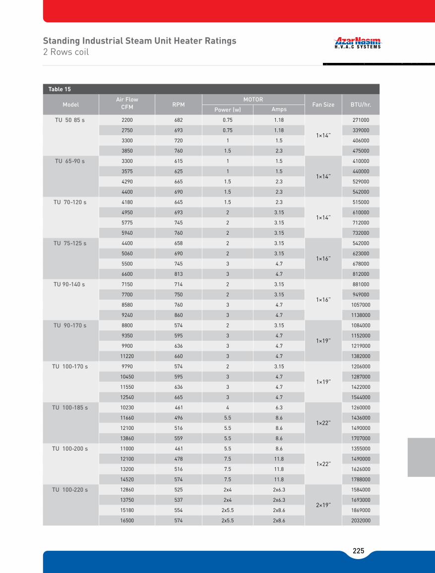
225
Standing Industrial Steam Unit Heater Ratings 2 Rows coil
Model
Table 15
MOTORBTU/hr.
Air Flow CFM AmpsPower (w)
RPM Fan Size
2�19
1�22
1�22
1�19
1�19
1�16
1�16
1�14
1�14
1�14
TU 50 85 s
TU 65-90 s
TU 70-120 s
TU 75-125 s
TU 90-140 s
TU 90-170 s
TU 100-170 s
TU 100-185 s
TU 100-200 s
TU 100-220 s
2200
2750
3300
3850
3300
3575
4290
4400
4180
4950
5775
5940
4400
5060
5500
6600
7150
7700
8580
9240
8800
9350
9900
11220
9790
10450
11550
12540
10230
11660
12100
13860
11000
12100
13200
14520
12860
13750
15180
16500
682
693
720
760
615
625
665
690
645
693
745
760
658
690
745
813
714
750
760
860
574
595
636
660
574
595
636
665
461
496
516
559
461
478
516
574
525
537
554
574
0.75
0.75
1
1.5
1
1
1.5
1.5
1.5
2
2
2
2
2
3
3
2
2
3
3
2
3
3
3
2
3
3
3
4
5.5
5.5
5.5
5.5
7.5
7.5
7.5
2x4
2x4
2x5.5
2x5.5
1.18
1.18
1.5
2.3
1.5
1.5
2.3
2.3
2.3
3.15
3.15
3.15
3.15
3.15
4.7
4.7
3.15
3.15
4.7
4.7
3.15
4.7
4.7
4.7
3.15
4.7
4.7
4.7
6.3
8.6
8.6
8.6
8.6
11.8
11.8
11.8
2x6.3
2x6.3
2x8.6
2x8.6
271000
339000
406000
475000
410000
440000
529000
542000
515000
610000
712000
732000
542000
623000
678000
812000
881000
949000
1057000
1138000
1084000
1152000
1219000
1382000
1206000
1287000
1422000
1544000
1260000
1436000
1490000
1707000
1355000
1490000
1626000
1788000
1584000
1693000
1869000
2032000

226
UNIT HEATER
RETURN CHANEL
Hot House Unit Heater
Note: All Dimensions in mm
300700650750
800750800
800750800
800800850
800800850
9009001000
90010001100
110011501250
110012001300
130014001600
BAWL
CoilWidth
100
150
180
No. ofRows
1
2
3
TU 100-100 W -S
Model
Table 16 Dimensions
TU 50 -40 W
TU 40 -50 W
TU 50 -50 W
TU 50 -60 W
TU 60 -60 W
TU 75 -75 W
TU 75 -75 W
TU 90 -90 W
TU 90 -90 W -S
-S
-S
-S
-S
-S
-S
-S
-S
H
300
300
300
300
300
300
300
300
300

227
Hot House, Hot Water Unit Heater Ratings2 Rows coil
Hot House, Hot Water Unit Heater Ratings3 Rows coil
0.780.5"14 ×1 151500001500
0.780.5"14 ×1 201980002000
1.180.75"14 ×1 252480002500
1.180.75"14 ×1 302990003000
2.31.5"16 ×1 363580003600
2.31.5"16 ×1 454480004500
3.152"18 ×1 555470005500
3.152"19 ×1 656460006500
4.73"19 ×1 807950008000
TU 50-40 w
TU 40-50 w
TU 50-50 w
TU 50-60 w
TU 60-60 w
TU 60-75 w
TU 75-75 w
TU 90-90 w
TU 90-90 w
6.34"22 ×1 10099400010000TU 100 -100 w
Model
Table 17
BTU/hr.Air Flow CFM
MOTOR
AmpsPower (w)
Fan SizeGPM
Water �ow
"14 ×1 24 0.780.5
"14 ×1 30 1.180.75
"14 ×1 39 1.180.75
"14 ×1 48 2.31.5
"16 ×1 55 2.31.5
"16 ×1 66 3.152
"18 ×1 81 3.152
"19 ×1 96 4.73
"19 ×1 108
TU 50-40 w
TU 40-50 w
TU 50-50 w
TU 50-60 w
TU 60-60 w
TU 60-75 w
TU 75-75 w
TU 90-90 w
TU 90-90 w 6.34
"22 ×1 132TU 100 -100 w
Model
Table 18
BTU/hr.Air Flow CFM
MOTOR
AmpsPower (w)
Fan Size
8.65
2000
2500
3200
4000
4600
5500
6800
8000
9000
11000
237000
297000
381000
475000
547000
654000
808000
950000
1069000
1307000
GPMWater �ow

228
Hothouse Steam Unit Heater Ratings1 Row coil
Hothouse Steam Unit Heater Ratings2 Rows coil
"14 ×1 0.780.5
"14 ×1 1.180.75
"14 ×1 1.180.75
"14 ×1 2.31.5
"16 ×1 2.31.5
"16 ×1 3.152
"18 ×1 3.152
"19 ×1 4.73
"19 ×1
TU 50-40 w
TU 40-50 w
TU 50-50 w
TU 50-60 w
TU 60-60 w
TU 60-75 w
TU 75-75 w
TU 90-90 w
TU 90-90 w 6.34
"22 ×1 TU 100 -100 w
Model
Table 19
BTU/hr.Air Flow CFM
MOTOR
AmpsPower (Hp)
Fan Size
8.65.5
2000
2500
3000
3800
4500
5400
6500
8200
10000
12000
200000
252000
300000
382000
452000
544000
655000
823000
1000000
1200000
"14 ×1
"14 ×1
1.180.75
"14 ×1
1.181.5
"14 ×1
2.31.5
"16 ×1
2.32
"16 ×1
3.152
"18 ×1
3.153
"19 ×1
4.73
"19 ×1
TU 50-40 w
TU 40-50 w
TU 50-50 w
TU 50-60 w
TU 60-60 w
TU 60-75 w
TU 75-75 w
TU 90-90 w
TU 90-90 w
6.34
"22 ×1 TU 100 -100 w
Model
Table 20
BTU/hr.Air Flow CFM
MOTOR
AmpsPower (Hp)
Fan Size
8.65.5
11.87.5
2500
3200
3900
5000
5500
7000
8000
9500
12000
14000
308000
393000
480000
615000
678000
861000
984000
1169000
1477000
1724000

229
MODEL SELECTION:Once determined the minimum volume of the air to be circulated inside the environment and Select the minimum number of units to install, the sizes and features of the units that better Fulfill the installation necessities have to be pointed out in the tables. Generally it's better to Select the units working at normal ration speed.
MAIN TENANCE RULES:Azar Nasim unit heaters are hydraulically and mechanically tested. For this reason, along Working time is guaranteed without defect. The operating and the duration of the unit heaters Can be improved and extended following a maintenance program as listed below.
FAN MOTOR ASSEMBLY:In case of various interventions of the magnetic starter, measure the current absorption (Amp) and be sure that it's not greater than the ratings of motor. The bearings are self Lubricated closed type and don�t require particular maintenance and lubrication. If they will Result particularly noisy; please order to replacing them, at the beginning of each working Period, control that the blade is clean and without fouling on the both sides on the contrary Dismount the blade and put into a degreasing solution.
HEATING COIL:At the beginning of each working period, it is necessary to clean the exchanging coil By means of blower with compressed air or brushing. In case of grease presence, Wash the finned pack with a degreasing solution and pay attention to don�t wet the motor and Affect a well done drying of the exchanging coil before starting. The necessity and Frequency of the cleaning depends on the dust inside the environment where the unit heaters Are installed. Generally the above maintenance is elected yearly before each winter. During such maintenance, control the fixing screws, in motor mounting, blade and brackets, Regarding the spare parts of the unit and the ratings of the motor.

230
Air Entering Condencer Temperature (°F)
Air - Cooled
Air Flow Rate (Ft.³/l\/lin)
Correction Factor for Entering Air Temprature
Condesing Temperature (°F)
Entering Air Temperature (°F)
Entering Dry Bulb Temperature (°F)
Entering VVet Bulb Temperature (°F)
Entering Water Temperature (°F)
Entering Hot Water Temperature (°F)
Coil Face Area Sq.. FT
Full Load Amps
Face Velocity (Ft/min)
Condenser Water Flow Rate
Normal Horse power
Enthalpy of Air Entering Evaporator Coil (Btu/Lb)
Enthalpy of Air Leaving Evaporator Coil (Btu/Lb)
Network Frequency (S-¹)
Compressor Power Input (kw)
Leaving Dry Bulb Temperature (°F)
Equivalent Length of Pipe From Package to Condenser Ft
Locked Rotate Amps
Pressure Drop (Feet of Water)
Phase
Rated Load Amps
Starting Current Amps
Sensible Heat Capacity (MBH)
Static Pressure (Inch of Water)
Total Capacity (MBH)
Total Heat Rejection (MBH)
Voltage
Water - Cooler
AEC
AC
CFM
CF
CT
EAT
EDB
EWB
EWT
EHT
FA
FLA
FV
CPM
HP
H1
H2
HZ
kw
LDB
Leq
LRA
PD
PH
RLA
SC
SHC
SP
TC
THR
V
W.C
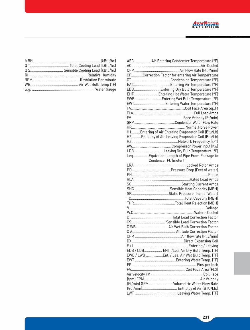
231
AEC..................Air Entering Condenser Temperature (°F)AC......................................................................Air-CooledCFM..............................................Air Flow Rate (Ft .³/min)CF............Correction Factor for entering Air TemperatureCT........................................Condensing Temperature (°F)EAT......................................Entering Air Temperature (°F)EDB...........................Entering Dry Bulb Temperature (°F)EHT.........................Entering Hot Water Temperature (°F)EWB.............................Entering Wet Bulb Temperature (°F)EWT................................Entering Water Temperature (°F)FA..............................................................Coil Face Area Sq..FtFLA....................................................................Full Load AmpsFV.....................................................Face Velocity (Ft/min)GPM............................................Condenser Water Flow RateHP............................................................Normal Horse PowerH1.........Entering of Air Entering Evaporator Coil (Btu/Lb)H2..........Enthalpy of Air Leaving Evaporator Coil (Btu/Lb)HZ...............................................Network Frequency (s-1)KW...........................................Compressor Power Input (Kw)LDB................................Leaving Dry Bulb Temperature (°F)Leq................Equivalent Length of Pipe From Package to Condenser Ft. (meter)LRA.....................................................Locked Rotor AmpsPD.............................................Pressure Drop (Feet of water)PH..............................................................................PhaseRLA.........................................................Rated Load AmpsSC...................................................Starting Current AmpsSHC....................................Sensible Heat Capacity (MBH)SP......................................Static Pressure (Inch of Water)TC......................................................Total Capacity (MBH)THR..........................................Total Heat Rejection (MBH)V.........................................................................................VoltageW.C......................................................................Water - CooledCT......................................... Total Load Correction FactorCS.................................. Sensible Load Correction FactorC WB................................ Air Wet Bulb Correction FactorC A........................................... Altitude Correction FactorCFM ..............................................Air flow rate (Ft.3/min)DX ....................................................Direct Expansion CoilE / L...................................................... Entering / LeavingEDB / LDB.................. ENT. /Lea. Air Dry Bulb Temp. (˚F)EWB / LWB ……………...Ent. / Lea. Air Wet Bulb Temp. (˚F)EWT .........................................Entering Water Temp. (˚F)FPI................................................................ Fins per InchFA...................................................... Coil Face Area (Ft.2)Air Velocity FV..................................................... Coil Face(fpm) FPM........................................................ Air Velocity(Ft/min) GPM........................ Volumetric Water Flow Rate(Gal/min)................................... Enthalpy of Air (BTU/Lb.)LWT ...........................................Leaving Water Temp. (˚F)
MBH ................................................................... (kBtu/hr.)Q T....................................... Total Cooling Load (kBtu/hr.)Q S................................. Sensible Cooling Load (kBtu/hr.)RH .........................................................Relative HumidityRPM ...............................................Revolution Per minuteWB................................................ Air Wet Bulb Temp (˚F)w.g. ............................................................... Water Gauge
232

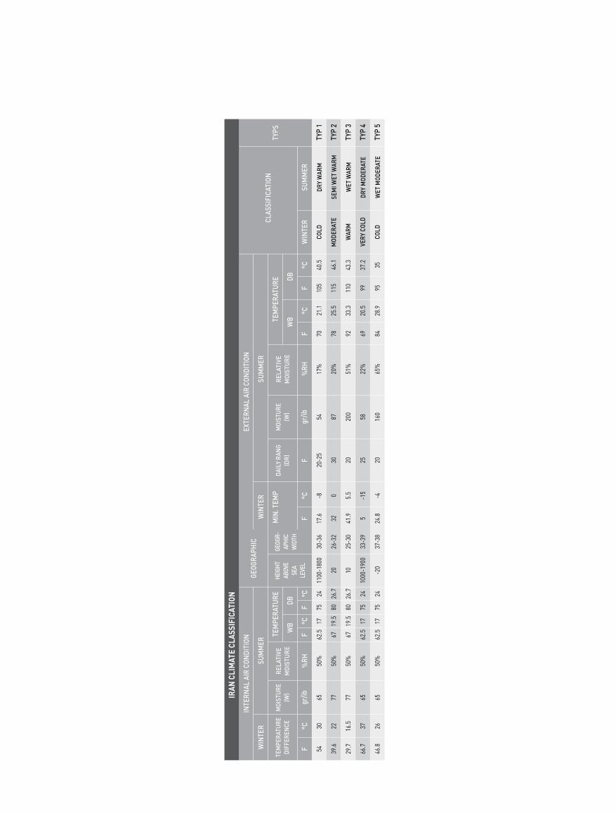
IRAN
CLI
MAT
E CL
ASSI
FICA
TION
INTE
RNAL
AIR
CON
DITI
ON
TEM
PERA
TURE
DIFF
EREN
CE
WIN
TER
SUM
MER
MOI
STUR
E(W
)
TEM
PERA
TURE
GEOG
RAPH
IC
HEIG
HTAB
OVE
SEA
LEVE
L
GEOG
R-AP
HIC
WID
TH
MIN
. TEM
P
EXTE
RNAL
AIR
CON
DITI
ON
DAIL
Y RA
NG
(DR)
WB
DB
CLAS
SIFI
CATI
ONW
INTE
RSU
MM
ER
TEM
PERA
TURE DB
WB
MOI
STUR
E(W
)RE
LATI
VE
MOI
STU
RERE
LATI
VE
MOI
STU
RE
TYPS
TYP
1
TYP
2
TYP
3
TYP
4
TYP
5
COLD
MOD
ERAT
E
WAR
M
VERY
COL
D
COLD
WIN
TER
DRY
WAR
M
SEM
I WET
WAR
M
WET
WAR
M
DRY
MOD
ERAT
E
WET
MOD
ERAT
E
SUM
MER
54 39.6
29.7
66.7
46.8
30 22 16.5 37 26
65 77 77 65 65
50%
50%
50%
50%
50%
62.5 67 67 62.5
62.5
17 19.5
19.5 17 17
75 80 80 75 75
24 26.7
26.7 24 24
1100
-180
0
20 10
1000
-190
0
-20
30-36
26-32
25-30
33-39
37-38
17.6 32 41.9 5 24.8
-8 0 5.5
-15 -4
20-25
30 20 25 20
54 87 200
58 160
17%
20%
51%
22%
65%
70 78 92 69 84
21.1
25.5
33.3
20.5
28.9
105
115
110
99 95
40.5
46.1
43.3
37.2 35
F°C
gr/ib
%RH
F°C
F°C
F°C
Fgr/ib
%RH
F°C
F°C

BR
L-BF
GSHFRSHF
ESHF
O
M
R
A
L
DRY-BULB
RELATIVE H
UMIDIT
Y
GR
AIN
OF
MO
ISTU
RE
SEN
SIB
LE H
EAT
FACT
ORO= OUTDOOR DESIGN
R= ROOM DESIGNM= MIXTUREA= TADPL= LIVING APPARATUS; ENTERING ROOMBF= BYPASS FACTORGSHF= GRAND SENSIBLE HEAT FACTORRSHF= ROOM SENSIBLE HEAT FACTORESHF= EFFECTIVE SENSIBLE HEAT FACTOR
In one HVAC system, fresh air (normally about %20 of local air) Mix with return air in mixing box, then mix point (M) with passing above refrigerant coil, changes to frost point (tadb) of device.discharging air spesification from refrigerant coil come to plat ratio of device (BF) (L point).
In one HVAC system indoor, in room according to fresh air ratio, needed air has ventilated through alit of windows, opening and closing doors, or exhaust fansand then return air has entered to mixing box by channels.
AIR PROCESS IN HVAC SYSTEM AIR CIRCULATION DIAGRAM IN HVAC SYSTEM

EXHAUST AIR
RETURN AIRROOM SPACE
OUT DOOR AIR
FILT
ER
MIXING BOX
MIXTURE AIR
BYPASS AIR
COOLING/HEATINGCOILS
LIVING AIR
AIR CONDITIONING APPARTUS CALCUL LESS
SUP
PLY
AIR
FILT
ER
FAN
RETURN AIR CONDITIONING SYSTEM DIAGRAM

ABCD: WINTER REST REGIONEFGH: SUMMER REST REGION
32
30
27
21
16
10
4
10 16 21 24 27 32 36
100% 90% 80% 70%
60%
50%
40%
30%
20%
10%27
%48
%65
%81%97 %91%84%75
%65%48
%34%60
%75%86
%94
%98 %94 %84%70 %50
A
B
C
D
E
F
G
H
DRY AIR TEMPERATURE (°C)HUMAN REST AREA
% OF P
ERSON IN R
EST

ARDEBIL
TABRIZURMIARASHT
ZANJAN
QAZVINSANANDAJ
HAMEDAN
KERMANSHAHARAK
QORAMABAD
ILAM
TEHRAN
BABOLSAR
GORGANBOJNORD
MASHHAD
SEMNAN
QOM
SARAQS
ISFAHAN
AHVAZ
TABAS
YAZD BIRJAND
YASOOJABADAN
SHIRAZ
RAFSANJAN
KERMAN
ZABOL
ZAHEDAN
LAAR
BOSHEHR
KANGAN BANDAR ABBAS
BANDAR LENGEH MINAB
JAASK CHABAHAR
TYPE 1TYPE 2TYPE 3TYPE 4TYPE 5
DRY WARMSEMI WET WARMWET WARMDRY MODERATEWET MODERATE

IRAN CITIES IN CLIMATE CLASSIFICATION
TYPE 1 TYPE 2 TYPE 3 TYPE 4 TYPE 5
ABADEH
ABARQU
ARDESTAN
ARDAKAN YAZD
ISFAHAN
IQLID
IMAM CITY
ILAM
BAQEIN
NAFT
BAFQ
BIRJAND
PASARGAD
TAFTAN
TEHRAN
JAHROM
JIROFT
QORAMABAD
QOMAYNI SHAHR
DAMQAN
DARGAZ
RAVAND
RAFSANJAN
ZAHEDAN
SABZEVAR
SEMNAN
SIRJAN
BABAK CITY
SHIRAZ
FERDOUS
FASA
QASR E SHIRIN
QOM
QAMSHEH
KASHAN
KASHMAR
KERMAN
KAHRIZAK
GARMSAR
GONABAD
NAEIN
NAJAFABAD
NEYRIZ
YASOJ
YAZD
ABADAN
AQAJARI
ANDIMESHG
AHVAZ
IRANSHAHR
IZEH
BAM
BEHBAHAN
JESR NADERI
HAMIDIYEH
QASH
DEZFOL
DASHT E ABBAS
DO GONBADAN
RAMEHRMAZ
ZABOL
SOOSANGERD
SHOUSH
SHOSHTAR
KAHNOJ
GACHSARAN
LAARMASQUE SOLEYMAN
HOVEYZEH
BORAZJANBANDAR IMAM QOMAYNI
BANDAR AMIR
BANDAR BOUSHEHR
JASKBANDAR QORAMSHAHR
BANDAR DEYLAM
BANDAR ABBAS
BANDAR GANAVEH
BANDAR MAHSHAHR
TONB E BOZORG
TONB E KOCHAK
ABOMOSA ISLAND
KHARK ISLAND
QESHM ISLAND
KISH ISLAND
LAVAN ISLAND
LARK ISLAND
MINOO ISLAND
HORMOZ ISLAND
HENGAM ISLAND
CHABAHAR ISLAND
MINAB
AZAR SHAHR
ASHTIAN
ABHAR
ARAK
ARDEBIL
URMIA
AZNA
ESLAMABAD
ESFARAYEN
ASHTARIEH
ALIGOODARZ
AHAR
\IRANSHAH
BAJGIRAN
BAZARGAN
BANEH
BOJNOORD
BOROJERD
BOIEN
BOEINZAHRA
BOOKAN
BIJAR
BISTOON
PAVEH
PIRANSHAHR
TABRIZ
TAKAB
TOISARKAN
HESARAK
QORAMDAREH
QOMEYN
QANSAR
QOY
DAMAVAND
DOOZDOOZAN
DEHLORAN
RODEHEN
RAVANSAR
ZANJAN
SARAB
SARDASHT
SAQEZ
SOOMAR
SHAHIN DEJ
SHEMIRAN
SHAHR E KORSD
SHIRVAN
SALMAS
SANANDAJ
SANQAR
QAZVIN
QOCHAN
KAMIRAN
KARAJ
MAKOO
MAHALAT
MARAQEH
MARIVAN
MESHKIN SHAHR
MASHHAD
MALAYER
MIANDOAB
MIANEH
NOSOOD
NEYSHABOOR
HARSIN
HAMEDAN
AZAD SHAHR
ASTARA
ASTANEH
AMOL
URMIA
BABOL
BABOLSAR
BANDAR ANZALI
BANDAR TORKAMAN
BANDAR GAZ
BEHSHAHR
TONEKABON
CHABOKSAR
CHALOS
RAMSAR
RASHT
RODSAR
RODBAR
SAARI
SIAHKAL
SOME SARA
FOOMAN
QAEM SHAHR
KALACHAY
GORGAN
LAHIJAN
LANGEROOD
MANJIL
NEKA
NOOR
NOSHAHR
HASHTPAR

SUMMER & WINTER INNER DESIGN ACCORDING TO HUMAN WELFARE CONDITIONS
Summer Winter
Without HumidifyWith HumidifyNormal LocationLuxury Location
Hotel, Houses, Apartments,Hospital, Of�ce, School
Places with Limited accupied: Bank, Barbery, Shop, Supermarket and so ...
Place With High Temperature: Confferance Hall,Mosque, Church, Restaurant, Cinema.
Industrial Buildings and factories:Machinanis Saloon.
TEMP.SWING
RELATIVEMOISTURE
DRYTEMP.
DRYTEMP.
RELATIVEMOISTURE
DRYTEMP.
RELATIVEMOISTURE
TEMP.SWING
DRYTEMP.
TEMP.SWING
BUILDING TYPE
74-76
76-78
76-78
77-80
50-45
50-45
55-50
55-45
77-79
78-80
78-80
80-85
50-45
50-45
60-65
60-50
2-4
2-4
1-2
3-6
74-76
72-74
72-74
68-72
35-30
35-30
40-35
36-30
-3 to -4
-3 to -4
-2 to -3
-4 to -6
75-77
73-75
74-76
70-74
-4
-4
-4
-6
HOUSES
SHOP
FACTORIES
CORRIDORS
CLASSROOM
W.C
HOSPITALS
HOTELS
PRIVATE ROOM
SURGERY ROOM
BATH
BED ROOM & BATH
DINNIG ROOM
WINNER INNER DESIGN TEMPERATURE FOR STRUCTURE
OFFICES
CINEMAS
KITCHENS
LOCATION TYPEINTERIOR TEMP. [°F]
COMMUNITIES HALL
PUBLIC BUILDINGS
SCH
OO
LS
DESIGN TEMP. [°F] INTERIOR TYPE
72-74
70-95
70
75
72
68-74
68-72
66
73-75
65-68
72-74
60-65
55-68
72-74
67-72
68-70
PROVIDED RANGES IN TEMPRATURE SWING COLUMN IS USED IN THERMOSTICE ROOMS.
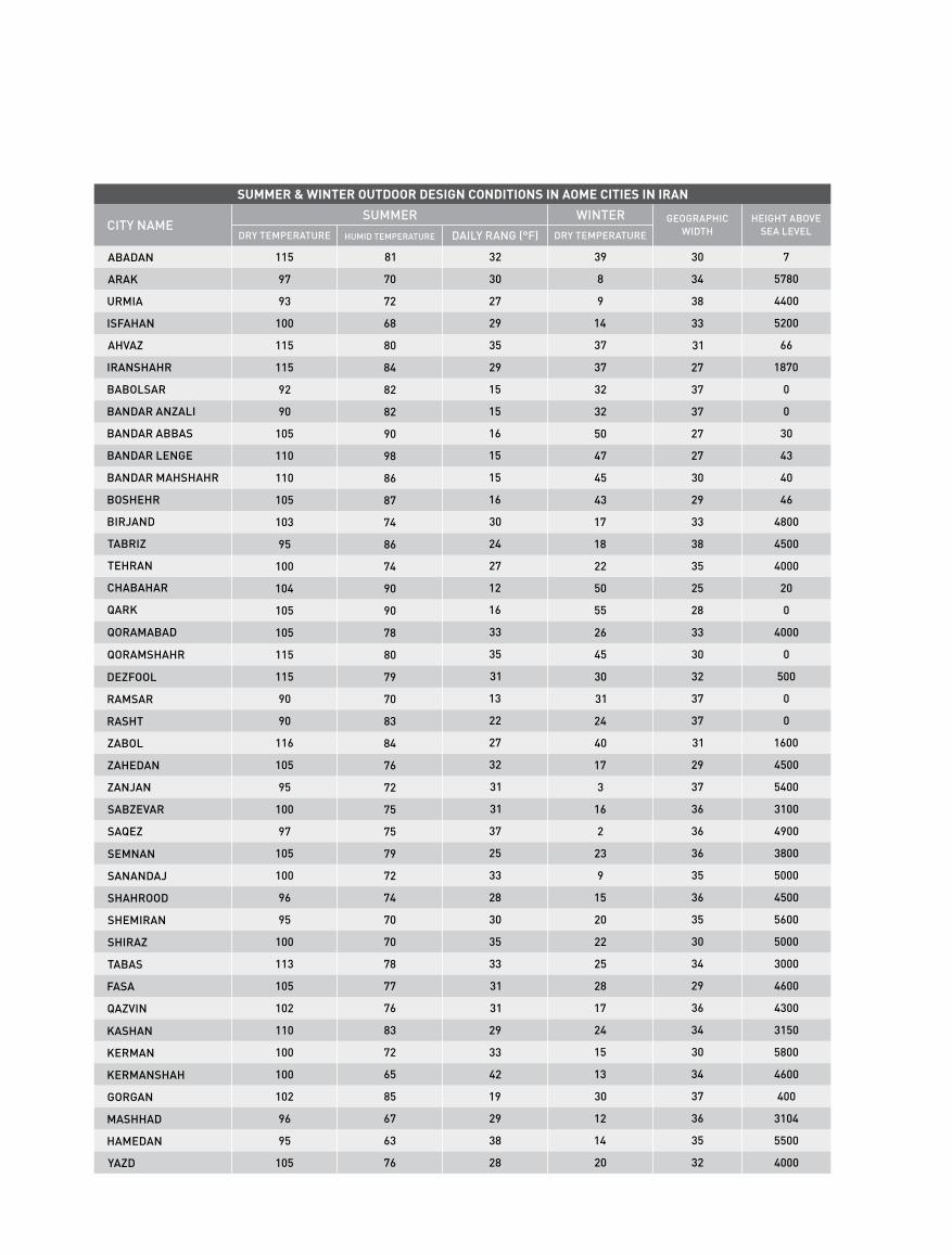
SUMMER & WINTER OUTDOOR DESIGN CONDITIONS IN AOME CITIES IN IRAN
HEIGHT ABOVE SEA LEVEL
GEOGRAPHIC WIDTH
WINTERDAILY RANG (°F)HUMID TEMPERATURE DRY TEMPERATURE
CITY NAMESUMMER
DRY TEMPERATURE
ABADAN
ARAK
URMIA
ISFAHAN
AHVAZ
IRANSHAHR
BABOLSAR
BANDAR ANZALI
BANDAR ABBAS
BANDAR LENGE
BANDAR MAHSHAHR
BOSHEHR
BIRJAND
TABRIZ
TEHRAN
CHABAHAR
QARK
QORAMABAD
QORAMSHAHR
DEZFOOL
RAMSAR
RASHT
ZABOL
ZAHEDAN
ZANJAN
SABZEVAR
SAQEZ
SEMNAN
SANANDAJ
SHAHROOD
SHEMIRAN
SHIRAZ
TABAS
FASA
QAZVIN
KASHAN
KERMAN
KERMANSHAH
GORGAN
MASHHAD
HAMEDAN
YAZD
7
5780
4400
5200
66
1870
0
0
30
43
40
46
4800
4500
4000
20
0
4000
0
500
0
0
1600
4500
5400
3100
4900
3800
5000
4500
5600
5000
3000
4600
4300
3150
5800
4600
400
3104
5500
4000
30
34
38
33
31
27
37
37
27
27
30
29
33
38
35
25
28
33
30
32
37
37
31
29
37
36
36
36
35
36
35
30
34
29
36
34
30
34
37
36
35
32
39
8
9
14
37
37
32
32
50
47
45
43
17
18
22
50
55
26
45
30
31
24
40
17
3
16
2
23
9
15
20
22
25
28
17
24
15
13
30
12
14
20
32
30
27
29
35
29
15
15
16
15
15
16
30
24
27
12
16
33
35
31
13
22
27
32
31
31
37
25
33
28
30
35
33
31
31
29
33
42
19
29
38
28
81
70
72
68
80
84
82
82
90
98
86
87
74
86
74
90
90
78
80
79
70
83
84
76
72
75
75
79
72
74
70
70
78
77
76
83
72
65
85
67
63
76
115
97
93
100
115
115
92
90
105
110
110
105
103
95
100
104
105
105
115
115
90
90
116
105
95
100
97
105
100
96
95
100
113
105
102
110
100
100
102
96
95
105

-10-5
05
1015
2025
3035
4045
5055
6065
7075
8085
9095
100105
110115
120125
130
DR
Y BU
LB TEM
PER
ATUR
E - °F
10 20 30 40 50 60 70 80 90 100
110
120
130
140
150
160
170
180
190
200
210
1015
2025
3035 40 45 50 55
55
60
60
65 70
ENTHALPY - BTU PER POUND OF DRY AIR
0
5
10
15
20
25
30
35
40
45
50
ENTHALPY - BTU PER POUND OF DRY AIR
SATURATION TEMPERATURE - °F
-50
05
510
1015
1520
2025
2530
3035
3540
4045
4550
5055
5560
6065
65
70
70
75
75
80
80
85WETBULB TEM
PERATURE - °F
85
90
15%25%2% 4% 6% 8%
10% R
ELATIVE HU
MID
ITY20%
30%
40%
50%60%
70%80%
90%
12.0
12.5
13.0
13.5
14.0 SPECIFIC VOLUME ft³/lb OF DRY AIR
14.5
15.0
15.5
HUMIDITY RATIO - GRAINS OF MOISTURE PER POUND OF DRY AIR
Linric Com
pany Psychrometric C
hart, ww
w.linric.com
.1 .2 .3 .4 .5 .6 .7 .8 .9 1 1.1
1.2
1.3
VAPOR PRESSURE - INCHES OF MERCURY
-20 0 10
20 25
30
35
40
45
50
55
60
65
70
75
80
85
DEW POINT - °F


Mamonieh Ind. Town,80 Km Tehran-Save HighwayTel: +98 (86) 45 25 00 12-23
اتوبان تهران ساوه-کیلومتر 80،شهرك صنعتی مأموهنیه
تلفن: 12-23 00 25 086-45