general 6shfl¿fdwlrqv base plates (for n-io) general specifications (gs) covers the specifications...
TRANSCRIPT

GeneralSpecifications
<<Contents>> <<Index>>
Models A2BN3D, A2BN4D, A2BN5DBase Plates (for N-IO)System Models: A2ZN3D, A2ZN4DC, A2ZN5DCN-IO I/O Unit
Yokogawa Electric Corporation2-9-32, Nakacho, Musashino-shi, Tokyo, 180-8750 JapanTel.: 81-422-52-5634 Fax.: 81-422-52-9802
GS 33J62F40-01EN
GS 33J62F40-01EN©Copyright Feb. 2015 (YK)
6th Edition Sep. 1, 2016 (YK)
nGENERALThis General Specifications (GS) covers the specifications of the Base plates for N-IO I/O units used in the N-IO system of CENTUM VP.There are two types of base plates, one for adaptors and the other for barriers.
nSTANDARD SPECIFICATIONSFor the installation environmental standards of this product, refer to the GS “N-IO System Overview” (GS 33J62A10-01EN).
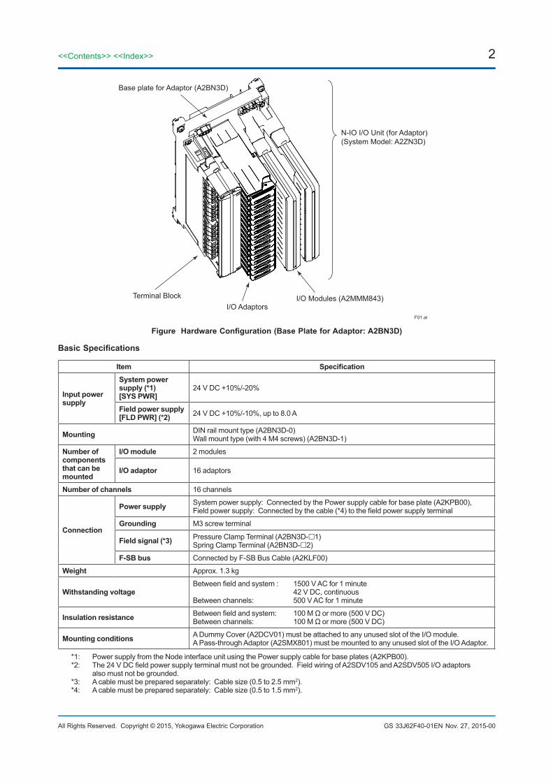
l Base plate for Adaptor (A2BN3D)This base plate allows communication with the Node interface unit via an F-SB bus by connecting the field signal to the terminal on the Base plate for adaptors.The Base plate for adaptors, one of the components of the N-IO I/O unit (for Adaptor) which is defined as A2ZN3D for the system model, allows the I/O module and various I/O adaptors depending on the signal type to be mounted to it. The I/O modules can be mounted in a single or dual-redundant configuration. Up to 16 I/O adaptors can be mounted per channel. Furthermore, this Base plate has a system power supply and field power supply interface and has a function to supply power to the I/O module and I/O adaptors from the Node interface unit via the Power supply cable for base plates (A2KPB00), and has a function to supply field power to the inside of the I/O adaptors by connecting the specified power line.The following shows the I/O module and I/O adaptors that can be mounted to the Base plate for adaptor.
Table I/O Module
Signal type Description Model
Universal Input/Output 16-channel, 24 V DC, Isolated A2MMM843 Analog/Digital I/O Module
Table I/O Adaptor
Signal type Description Model
Analog input 0 to 10 kHz A2SAP105 Pulse Input Adaptor
Digital input 24 V DC, voltage input, non-voltage contact input A2SDV105 Digital Input Adaptor
Digital output24V DC/0.5 A current source A2SDV505 Digital Output Adaptor
24 V DC/0.5 A, non-voltage contact output A2SDV506 Relay Output Adaptor
— I/O signal non conversion A2SMX801 Pass-through I/O Signal Adaptor
[Release 6]
2
All Rights Reserved. Copyright © 2015, Yokogawa Electric Corporation
<<Contents>> <<Index>>
GS 33J62F40-01EN Nov. 27, 2015-00
F01.ai
Terminal Block
N-IO I/O Unit (for Adaptor)(System Model: A2ZN3D)
I/O Adaptors
Base plate for Adaptor (A2BN3D)
I/O Modules (A2MMM843)
Figure Hardware Configuration (Base Plate for Adaptor: A2BN3D)
Basic Specifications
Item Specification
Input power supply
System power supply (*1)[SYS PWR]
24 V DC +10%/-20%
Field power supply[FLD PWR] (*2) 24 V DC +10%/-10%, up to 8.0 A
Mounting DIN rail mount type (A2BN3D-0)Wall mount type (with 4 M4 screws) (A2BN3D-1)
Number of components that can be mounted
I/O module 2 modules
I/O adaptor 16 adaptors
Number of channels 16 channels
Connection
Power supply System power supply: Connected by the Power supply cable for base plate (A2KPB00), Field power supply: Connected by the cable (*4) to the field power supply terminal
Grounding M3 screw terminal
Field signal (*3) Pressure Clamp Terminal (A2BN3D-1) Spring Clamp Terminal (A2BN3D-2)
F-SB bus Connected by F-SB Bus Cable (A2KLF00)
Weight Approx. 1.3 kg
Withstanding voltageBetween field and system : 1500 V AC for 1 minute 42 V DC, continuousBetween channels: 500 V AC for 1 minute
Insulation resistance Between field and system: 100 M Ω or more (500 V DC)Between channels: 100 M Ω or more (500 V DC)
Mounting conditions A Dummy Cover (A2DCV01) must be attached to any unused slot of the I/O module.A Pass-through Adaptor (A2SMX801) must be mounted to any unused slot of the I/O Adaptor.
*1: Power supply from the Node interface unit using the Power supply cable for base plates (A2KPB00).*2: The 24 V DC field power supply terminal must not be grounded. Field wiring of A2SDV105 and A2SDV505 I/O adaptors
also must not be grounded.*3: A cable must be prepared separately: Cable size (0.5 to 2.5 mm2).*4: A cable must be prepared separately: Cable size (0.5 to 1.5 mm2).

3<<Contents>> <<Index>>
All Rights Reserved. Copyright © 2015, Yokogawa Electric Corporation GS 33J62F40-01EN
l Base Plate for barrier (A2BN4D)This base plate allows for communication with the node interface unit via an F-SB bus by connecting the field signal to the terminal on the intrinsic safety (hereinafter I.S.) barrier mounted to this base plate.The Base plate for barrier, one of the components of the N-IO I/O unit (for Barrier) which is defined as A2ZN4DC for the system model, allows for mounting the I/O module and various I.S. barriers from MTL Instruments Group Limited (hereinafter MTL) to it. The I.S. barrier has a field connection terminal (pressure clamp terminal) for connecting the field signal. The I/O modules can be mounted in a single or dual-redundant configuration. Up to 16 I.S. barriers can be mounted per channel. Furthermore, this base plate has a system power supply and field power supply interface and has a function to supply power to the I/O module from the Node interface unit via the Power supply cable for base plate (A2KPB00), and has a function to supply field power to the I.S. barriers by connecting the specified power line. The following shows the I/O module and I.S. barriers that can be mounted to this base plate.
Table I/O Module
Signal Type Description Model
Universal Input/Output Analog/Digital I/O Module (16-channel, 24 V DC, isolated) A2MMM843
Table MTL’s I.S. barriers
Signal Type Description Model
Analog Input4 to 20 mA, 2/3 wire, HART MTL4541Y
4 to 20 mA, 4 wire, HART MTL4541YA
Analog Output 4 to 20 mA, HART MTL4545Y
Digital Input Dry contact or NAMUR, LFD MTL4514N
Digital OutputVoltage output MTL4521Y
Voltage output, LFD MTL4523Y
Temp. Input TC/RTD MTL4573Y
Base plate for Barrier(A2BN4D-200C0)
F02E.ai
I/O Modules (A2MMM843)MTL’s I.S. barriers MTL’s I.S. barriers
Base plate for Barrier(A2BN4D-200D0)
BARRIERPWR BUS 1 BUS 2
BU
S 2
SYSPWRFS1
FS1
A2BN4D-200C0 S1
+ _
_+
2.5A-T
TM1
TM2
1
2
3
4
1113
6
7
8
5
11
12
10
9
15
16
14
13
IO2IO1 IO2
_SYSPWR
TM1
IO1
2.5A-T
FS1
+ _
BARRIERPWRBUS 1 BUS 2
TM2
A2BN4D-200D0 S1
16
15
14
13
12
11
10
9
8
7
6
5
4
3
2
1
+
Measurement Technology Ltd.Luton, England.
UNITNODEUNITNODE
N-IO I/O Unit (for Barrie)(System Model: A2ZN4DC)
Figure Hardware Configuration (Base Plate for Barrier: A2BN4D)
June 30, 2015-00
4
All Rights Reserved. Copyright © 2015, Yokogawa Electric Corporation
<<Contents>> <<Index>>
GS 33J62F40-01EN
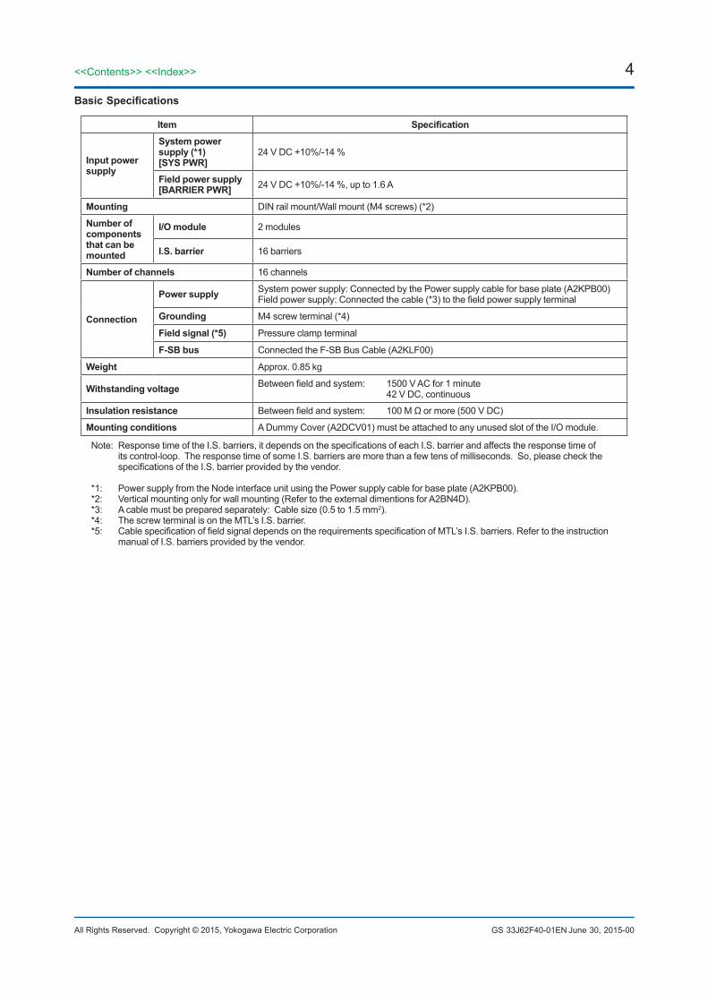
Basic Specifications
Item Specification
Input power supply
System power supply (*1)[SYS PWR]
24 V DC +10%/-14 %
Field power supply[BARRIER PWR] 24 V DC +10%/-14 %, up to 1.6 A
Mounting DIN rail mount/Wall mount (M4 screws) (*2)
Number of components that can be mounted
I/O module 2 modules
I.S. barrier 16 barriers
Number of channels 16 channels
Connection
Power supply System power supply: Connected by the Power supply cable for base plate (A2KPB00)Field power supply: Connected the cable (*3) to the field power supply terminal
Grounding M4 screw terminal (*4)
Field signal (*5) Pressure clamp terminal
F-SB bus Connected the F-SB Bus Cable (A2KLF00)
Weight Approx. 0.85 kg
Withstanding voltage Between field and system: 1500 V AC for 1 minute 42 V DC, continuous
Insulation resistance Between field and system: 100 M Ω or more (500 V DC)
Mounting conditions A Dummy Cover (A2DCV01) must be attached to any unused slot of the I/O module.
Note: Response time of the I.S. barriers, it depends on the specifications of each I.S. barrier and affects the response time of its control-loop. The response time of some I.S. barriers are more than a few tens of milliseconds. So, please check the specifications of the I.S. barrier provided by the vendor.
*1: Power supply from the Node interface unit using the Power supply cable for base plate (A2KPB00).*2: Vertical mounting only for wall mounting (Refer to the external dimentions for A2BN4D).*3: A cable must be prepared separately: Cable size (0.5 to 1.5 mm2).*4: The screw terminal is on the MTL’s I.S. barrier.*5: Cable specification of field signal depends on the requirements specification of MTL’s I.S. barriers. Refer to the instruction
manual of I.S. barriers provided by the vendor.
June 30, 2015-00
5<<Contents>> <<Index>>
All Rights Reserved. Copyright © 2015, Yokogawa Electric Corporation GS 33J62F40-01EN Sep. 1, 2016-00
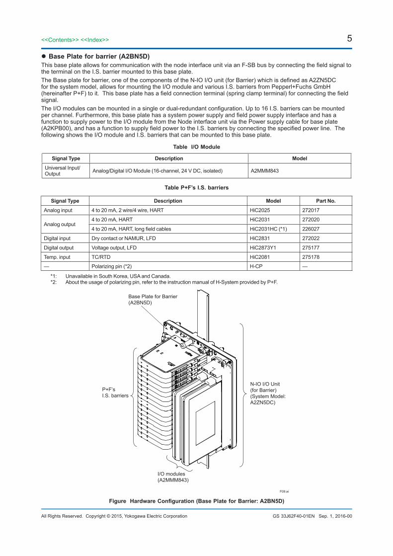
l Base Plate for barrier (A2BN5D)This base plate allows for communication with the node interface unit via an F-SB bus by connecting the field signal to the terminal on the I.S. barrier mounted to this base plate.The Base plate for barrier, one of the components of the N-IO I/O unit (for Barrier) which is defined as A2ZN5DC for the system model, allows for mounting the I/O module and various I.S. barriers from Pepperl+Fuchs GmbH (hereinafter P+F) to it. This base plate has a field connection terminal (spring clamp terminal) for connecting the field signal. The I/O modules can be mounted in a single or dual-redundant configuration. Up to 16 I.S. barriers can be mounted per channel. Furthermore, this base plate has a system power supply and field power supply interface and has a function to supply power to the I/O module from the Node interface unit via the Power supply cable for base plate (A2KPB00), and has a function to supply field power to the I.S. barriers by connecting the specified power line. The following shows the I/O module and I.S. barriers that can be mounted to this base plate.
Table I/O Module
Signal Type Description Model
Universal Input/Output Analog/Digital I/O Module (16-channel, 24 V DC, isolated) A2MMM843
Table P+F’s I.S. barriers
Signal Type Description Model Part No.
Analog input 4 to 20 mA, 2 wire/4 wire, HART HiC2025 272017
Analog output4 to 20 mA, HART HiC2031 272020
4 to 20 mA, HART, long field cables HiC2031HC (*1) 226027
Digital input Dry contact or NAMUR, LFD HiC2831 272022
Digital output Voltage output, LFD HiC2873Y1 275177
Temp. input TC/RTD HiC2081 275178
— Polarizing pin (*2) H-CP —
*1: Unavailable in South Korea, USA and Canada.*2: About the usage of polarizing pin, refer to the instruction manual of H-System provided by P+F.
F09.ai
Base Plate for Barrier(A2BN5D)
I/O modules(A2MMM843)
N-IO I/O Unit (for Barrier)(System Model:A2ZN5DC)
P+F’sI.S. barriers
Figure Hardware Configuration (Base Plate for Barrier: A2BN5D)
6
All Rights Reserved. Copyright © 2015, Yokogawa Electric Corporation
<<Contents>> <<Index>>
GS 33J62F40-01EN
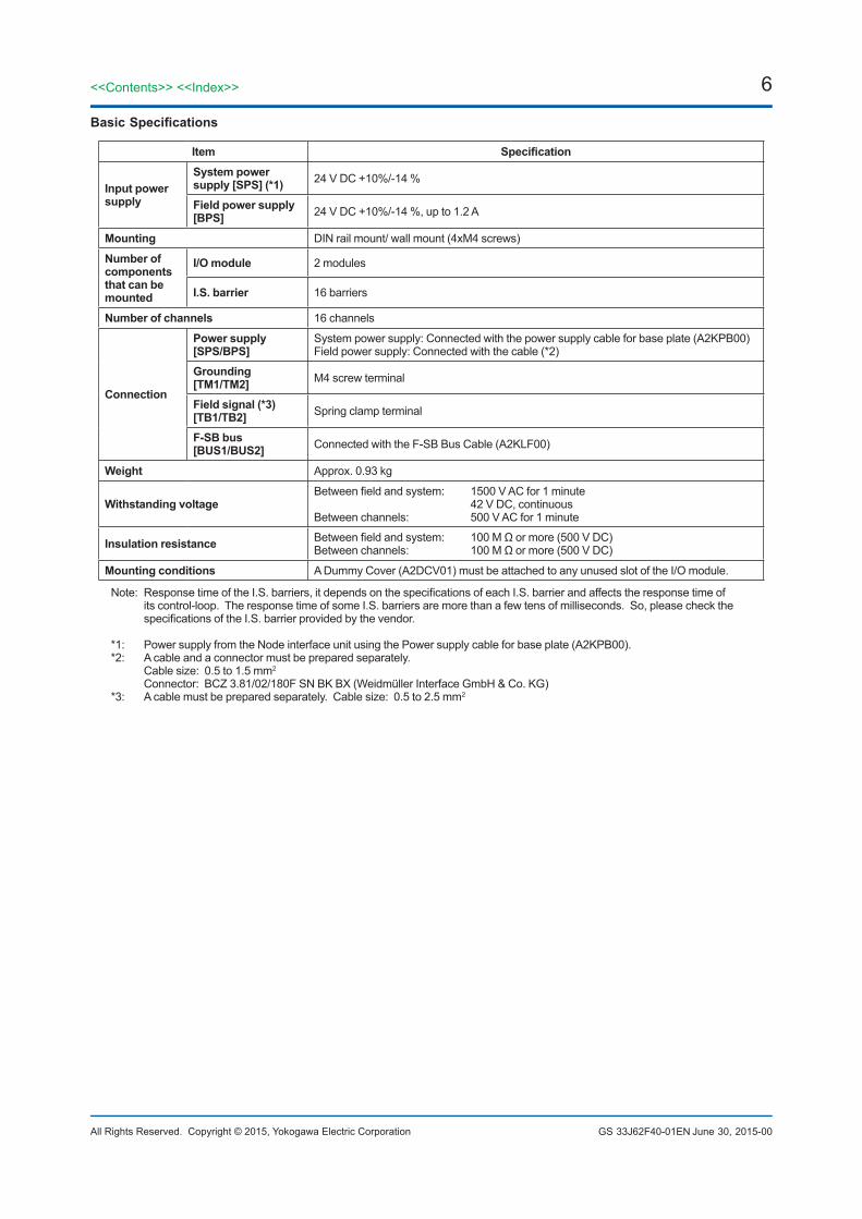
Basic Specifications
Item Specification
Input power supply
System power supply [SPS] (*1) 24 V DC +10%/-14 %
Field power supply [BPS] 24 V DC +10%/-14 %, up to 1.2 A
Mounting DIN rail mount/ wall mount (4xM4 screws)
Number of components that can be mounted
I/O module 2 modules
I.S. barrier 16 barriers
Number of channels 16 channels
Connection
Power supply[SPS/BPS]
System power supply: Connected with the power supply cable for base plate (A2KPB00)Field power supply: Connected with the cable (*2)
Grounding[TM1/TM2] M4 screw terminal
Field signal (*3)[TB1/TB2] Spring clamp terminal
F-SB bus[BUS1/BUS2] Connected with the F-SB Bus Cable (A2KLF00)
Weight Approx. 0.93 kg
Withstanding voltage Between field and system: 1500 V AC for 1 minute 42 V DC, continuousBetween channels: 500 V AC for 1 minute
Insulation resistance Between field and system: 100 M Ω or more (500 V DC)Between channels: 100 M Ω or more (500 V DC)
Mounting conditions A Dummy Cover (A2DCV01) must be attached to any unused slot of the I/O module.
Note: Response time of the I.S. barriers, it depends on the specifications of each I.S. barrier and affects the response time of its control-loop. The response time of some I.S. barriers are more than a few tens of milliseconds. So, please check the specifications of the I.S. barrier provided by the vendor.
*1: Power supply from the Node interface unit using the Power supply cable for base plate (A2KPB00).*2: A cable and a connector must be prepared separately. Cable size: 0.5 to 1.5 mm2 Connector: BCZ 3.81/02/180F SN BK BX (Weidmüller Interface GmbH & Co. KG)*3: A cable must be prepared separately. Cable size: 0.5 to 2.5 mm2
June 30, 2015-00
7<<Contents>> <<Index>>
All Rights Reserved. Copyright © 2015, Yokogawa Electric Corporation GS 33J62F40-01EN
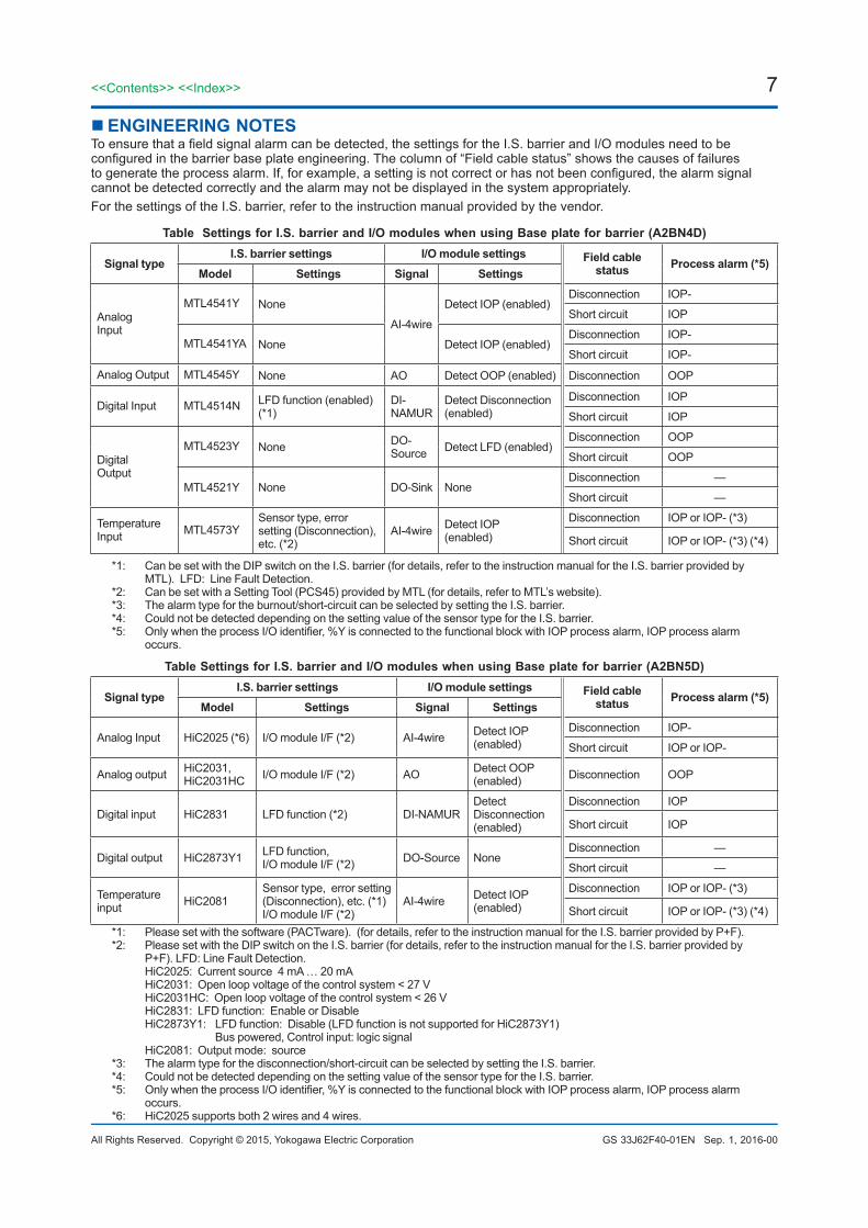
n ENGINEERING NOTESTo ensure that a field signal alarm can be detected, the settings for the I.S. barrier and I/O modules need to be configured in the barrier base plate engineering. The column of “Field cable status” shows the causes of failures to generate the process alarm. If, for example, a setting is not correct or has not been configured, the alarm signal cannot be detected correctly and the alarm may not be displayed in the system appropriately. For the settings of the I.S. barrier, refer to the instruction manual provided by the vendor.
Table Settings for I.S. barrier and I/O modules when using Base plate for barrier (A2BN4D)
Signal typeI.S. barrier settings I/O module settings Field cable
status Process alarm (*5)Model Settings Signal Settings
Analog Input
MTL4541Y None
AI-4wire
Detect IOP (enabled)Disconnection IOP-
Short circuit IOP
MTL4541YA None Detect IOP (enabled)Disconnection IOP-
Short circuit IOP-
Analog Output MTL4545Y None AO Detect OOP (enabled) Disconnection OOP
Digital Input MTL4514N LFD function (enabled) (*1)
DI-NAMUR
Detect Disconnection (enabled)
Disconnection IOP
Short circuit IOP
Digital Output
MTL4523Y None DO-Source Detect LFD (enabled)
Disconnection OOP
Short circuit OOP
MTL4521Y None DO-Sink NoneDisconnection —
Short circuit —
Temperature Input MTL4573Y
Sensor type, error setting (Disconnection), etc. (*2)
AI-4wire Detect IOP(enabled)
Disconnection IOP or IOP- (*3)
Short circuit IOP or IOP- (*3) (*4)
*1: Can be set with the DIP switch on the I.S. barrier (for details, refer to the instruction manual for the I.S. barrier provided by MTL). LFD: Line Fault Detection.
*2: Can be set with a Setting Tool (PCS45) provided by MTL (for details, refer to MTL’s website).*3: The alarm type for the burnout/short-circuit can be selected by setting the I.S. barrier.*4: Could not be detected depending on the setting value of the sensor type for the I.S. barrier.*5: Only when the process I/O identifier, %Y is connected to the functional block with IOP process alarm, IOP process alarm
occurs.
Table Settings for I.S. barrier and I/O modules when using Base plate for barrier (A2BN5D)
Signal typeI.S. barrier settings I/O module settings Field cable
status Process alarm (*5)Model Settings Signal Settings
Analog Input HiC2025 (*6) I/O module I/F (*2) AI-4wire Detect IOP(enabled)
Disconnection IOP-
Short circuit IOP or IOP-
Analog output HiC2031, HiC2031HC I/O module I/F (*2) AO Detect OOP
(enabled) Disconnection OOP
Digital input HiC2831 LFD function (*2) DI-NAMURDetect Disconnection(enabled)
Disconnection IOP
Short circuit IOP
Digital output HiC2873Y1 LFD function, I/O module I/F (*2) DO-Source None
Disconnection —
Short circuit —
Temperature input HiC2081
Sensor type, error setting (Disconnection), etc. (*1)I/O module I/F (*2)
AI-4wire Detect IOP (enabled)
Disconnection IOP or IOP- (*3)
Short circuit IOP or IOP- (*3) (*4)
*1: Please set with the software (PACTware). (for details, refer to the instruction manual for the I.S. barrier provided by P+F).*2: Please set with the DIP switch on the I.S. barrier (for details, refer to the instruction manual for the I.S. barrier provided by
P+F). LFD: Line Fault Detection. HiC2025: Current source 4 mA … 20 mA HiC2031: Open loop voltage of the control system < 27 V HiC2031HC: Open loop voltage of the control system < 26 V HiC2831: LFD function: Enable or Disable HiC2873Y1: LFD function: Disable (LFD function is not supported for HiC2873Y1) Bus powered, Control input: logic signal HiC2081: Output mode: source*3: The alarm type for the disconnection/short-circuit can be selected by setting the I.S. barrier.*4: Could not be detected depending on the setting value of the sensor type for the I.S. barrier.*5: Only when the process I/O identifier, %Y is connected to the functional block with IOP process alarm, IOP process alarm
occurs.*6: HiC2025 supports both 2 wires and 4 wires.
Sep. 1, 2016-00
8
All Rights Reserved. Copyright © 2015, Yokogawa Electric Corporation
<<Contents>> <<Index>>
GS 33J62F40-01EN
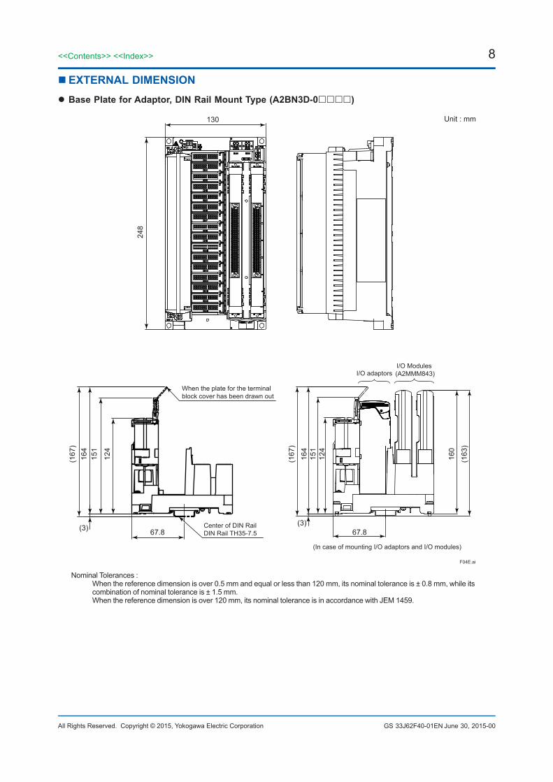
nEXTERNAL DIMENSIONl Base Plate for Adaptor, DIN Rail Mount Type (A2BN3D-0)
F04E.ai
130
248
(167
)
(3)(3)
67.8 67.8
164
151
124
(167
)
164
160
(163
)
151
124
Unit : mm
When the plate for the terminal block cover has been drawn out
I/O Modules (A2MMM843)I/O adaptors
(In case of mounting I/O adaptors and I/O modules)
Center of DIN RailDIN Rail TH35-7.5
Nominal Tolerances : When the reference dimension is over 0.5 mm and equal or less than 120 mm, its nominal tolerance is ± 0.8 mm, while its
combination of nominal tolerance is ± 1.5 mm. When the reference dimension is over 120 mm, its nominal tolerance is in accordance with JEM 1459.
June 30, 2015-00
9<<Contents>> <<Index>>
All Rights Reserved. Copyright © 2015, Yokogawa Electric Corporation GS 33J62F40-01EN
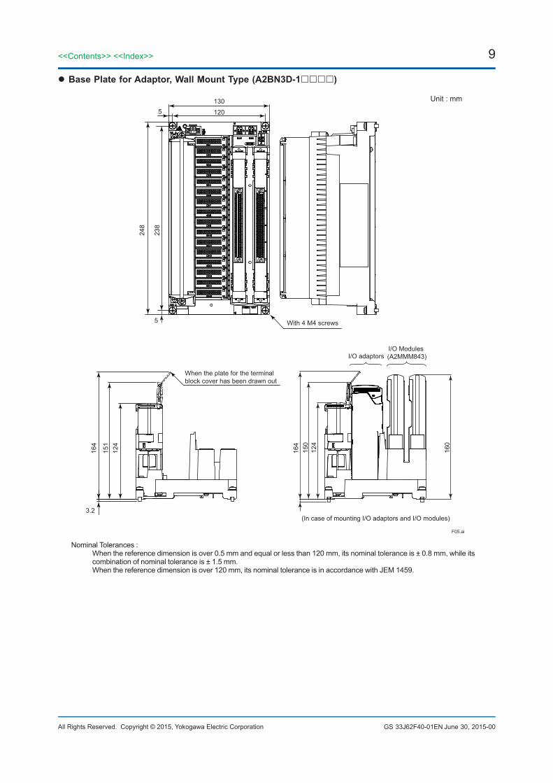
l Base Plate for Adaptor, Wall Mount Type (A2BN3D-1)
F05.ai
Unit : mm130
120
248
238
5
3.2
164
164
150
124
160
151
124
5
With 4 M4 screws
When the plate for the terminal block cover has been drawn out
I/O Modules (A2MMM843)I/O adaptors
(In case of mounting I/O adaptors and I/O modules)
Nominal Tolerances : When the reference dimension is over 0.5 mm and equal or less than 120 mm, its nominal tolerance is ± 0.8 mm, while its
combination of nominal tolerance is ± 1.5 mm. When the reference dimension is over 120 mm, its nominal tolerance is in accordance with JEM 1459.
June 30, 2015-00
10
All Rights Reserved. Copyright © 2015, Yokogawa Electric Corporation
<<Contents>> <<Index>>
GS 33J62F40-01EN
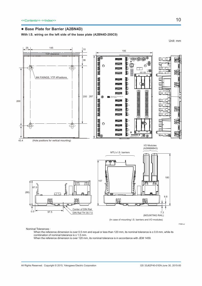
l Base Plate for Barrier (A2BN4D)With I.S. wiring on the left side of the base plate (A2BN4D-200C0)
BARRIERPWR BUS 1 BUS 2
BU
S 2
SYSPWRFS1
FS1
A2BN4D-200C0 S1
+ _
_+
Measurement Technology Ltd.Luton, England
NODE UNIT
TM1
TM2
!
2.5A-T
1
2
3
4
5
6
7
8
9
10
11
12
13
14
15
16
IO1 IO2
Unit: mm
195
180
87.5
(88)
0.5 97.5
157
6.8
7.3(MOUNTING RAIL)
(In case of mounting I.S. barriers and I/O modules)
F06E.ai
Center of DIN RailDIN Rail TH 35-7.5
I/O Modules (A2MMM843)
MTL’s I.S. barriers
287200
TOP clearance
36
43.4
200
M4 FIXINGS, YTP 4Positions.
1014525
(Hole positions for vertical mounting)
Nominal Tolerances : When the reference dimension is over 0.5 mm and equal or less than 120 mm, its nominal tolerance is ± 0.8 mm, while its
combination of nominal tolerance is ± 1.5 mm. When the reference dimension is over 120 mm, its nominal tolerance is in accordance with JEM 1459.
June 30, 2015-00
11<<Contents>> <<Index>>
All Rights Reserved. Copyright © 2015, Yokogawa Electric Corporation GS 33J62F40-01EN
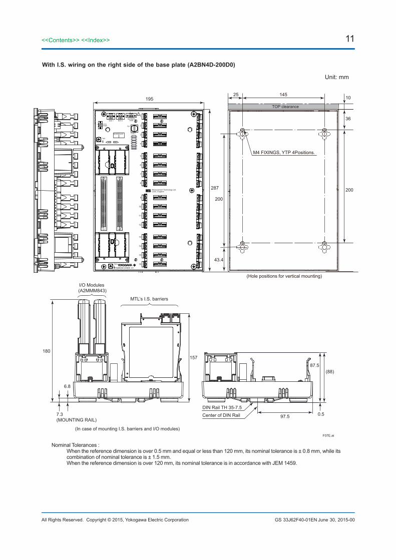
With I.S. wiring on the right side of the base plate (A2BN4D-200D0)
BUS 1 BUS 2BARRIER
PWR
SYSPWR
TM1
IO1 IO2
FS1
2.5A-T
+
+
-
-
Measurement Technology Ltd.Luton, England
1
2
3
4
5
6
7
8
9
10
11
12
13
14
15
16
A2BN4D-200D0 S1
TM2
UNITNODE
Unit: mm
195
287
180
87.5(88)
0.597.5
157
F07E.ai
6.8
7.3(MOUNTING RAIL)
(In case of mounting I.S. barriers and I/O modules)
Center of DIN Rail
DIN Rail TH 35-7.5
I/O Modules (A2MMM843)
MTL’s I.S. barriers
200
TOP clearance
36
43.4
200
M4 FIXINGS, YTP 4Positions.
1014525
(Hole positions for vertical mounting)
Nominal Tolerances : When the reference dimension is over 0.5 mm and equal or less than 120 mm, its nominal tolerance is ± 0.8 mm, while its
combination of nominal tolerance is ± 1.5 mm. When the reference dimension is over 120 mm, its nominal tolerance is in accordance with JEM 1459.
June 30, 2015-00
12
All Rights Reserved. Copyright © 2015, Yokogawa Electric Corporation
<<Contents>> <<Index>>
GS 33J62F40-01EN
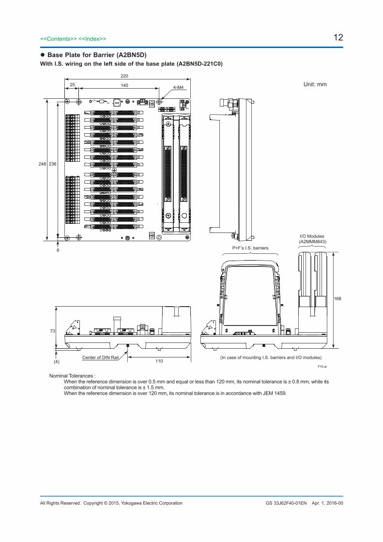
l Base Plate for Barrier (A2BN5D)With I.S. wiring on the left side of the base plate (A2BN5D-221C0)
220
248 236
14025
6
110Center of DIN Rail
73
(4)
168
4-M4
F10.ai
Unit: mm
(In case of mounting I.S. barriers and I/O modules)
I/O Modules (A2MMM843)
P+F’s I.S. barriers
Nominal Tolerances : When the reference dimension is over 0.5 mm and equal or less than 120 mm, its nominal tolerance is ± 0.8 mm, while its
combination of nominal tolerance is ± 1.5 mm. When the reference dimension is over 120 mm, its nominal tolerance is in accordance with JEM 1459.
Apr. 1, 2016-00
13<<Contents>> <<Index>>
All Rights Reserved. Copyright © 2015, Yokogawa Electric Corporation GS 33J62F40-01EN
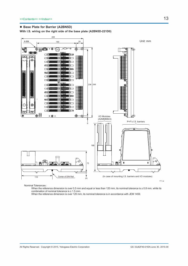
l Base Plate for Barrier (A2BN5D)With I.S. wiring on the right side of the base plate (A2BN5D-221D0)
220
248236
140 25
6
110 Center of DIN Rail
73
168
(4)F11.ai
4-M4 Unit: mm
(In case of mounting I.S. barriers and I/O modules)
I/O Modules (A2MMM843)
P+F’s I.S. barriers
Nominal Tolerances : When the reference dimension is over 0.5 mm and equal or less than 120 mm, its nominal tolerance is ± 0.8 mm, while its
combination of nominal tolerance is ± 1.5 mm. When the reference dimension is over 120 mm, its nominal tolerance is in accordance with JEM 1459.
June 30, 2015-00
14
All Rights Reserved. Copyright © 2015, Yokogawa Electric Corporation
<<Contents>> <<Index>>
GS 33J62F40-01EN
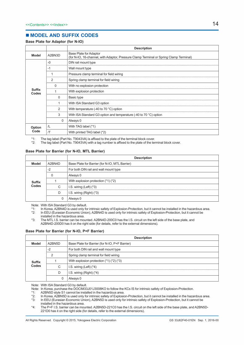
nMODEL AND SUFFIX CODESBase Plate for Adaptor (for N-IO)
Description
Model A2BN3D Base Plate for Adaptor (for N-IO, 16-channel, with Adaptor, Pressure Clamp Terminal or Spring Clamp Terminal)
Suffix Codes
-0 DIN rail mount type
-1 Wall mount type
1 Pressure clamp terminal for field wiring
2 Spring clamp terminal for field wiring
0 With no explosion protection
1 With explosion protection
0 Basic type
1 With ISA Standard G3 option
2 With temperature (-40 to 70 °C) option
3 With ISA Standard G3 option and temperature (-40 to 70 °C) option
0 Always 0
Option Code
/L With TAG label (*1)
/T With printed TAG label (*2)
*1: The tag label (Part No. T9043VA) is affixed to the plate of the terminal block cover.*2: The tag label (Part No. T9043VA) with a tag number is affixed to the plate of the terminal block cover.
Base Plate for Barrier (for N-IO, MTL Barrier)
Description
Model A2BN4D Base Plate for Barrier (for N-IO, MTL Barrier)
Suffix Codes
-2 For both DIN rail and wall mount type
0 Always 0
1 With explosion protection (*1) (*2)
C I.S. wiring (Left) (*3)
D I.S. wiring (Right) (*3)
0 Always 0
Note: With ISA Standard G3 by default. *1: In Korea, A2BN4D is used only for intrinsic safety of Explosion-Protection, but it cannot be installed in the hazardous area.*2: In EEU (Eurasian Economic Union), A2BN4D is used only for intrinsic safety of Explosion-Protection, but it cannot be
installed in the hazardous area.*3: The MTL I.S. barrier can be mounted. A2BN4D-200C0 has the I.S. circuit on the left side of the base plate, and
A2BN4D-200D0 has it on the right side (for details, refer to the external dimensions).
Base Plate for Barrier (for N-IO, P+F Barrier)
Description
Model A2BN5D Base Plate for Barrier (for N-IO, P+F Barrier)
Suffix Codes
-2 For both DIN rail and wall mount type
2 Spring clamp terminal for field wiring
1 With explosion protection (*1) (*2) (*3)
C I.S. wiring (Left) (*4)
D I.S. wiring (Right) (*4)
0 Always 0
Note: With ISA Standard G3 by default.Note: In Korea, purchase the DOCIM33J01J3008KO to follow the KCs IS for intrinsic safety of Explosion-Protection.*1: A2BN5D style S1 cannot be installed in the hazardous area.*2: In Korea, A2BN5D is used only for intrinsic safety of Explosion-Protection, but it cannot be installed in the hazardous area.*3: In EEU (Eurasian Economic Union), A2BN5D is used only for intrinsic safety of Explosion-Protection, but it cannot be
installed in the hazardous area.*4: The P+F I.S. barrier can be mounted. A2BN5D-221C0 has the I.S. circuit on the left side of the base plate, and A2BN5D-
221D0 has it on the right side (for details, refer to the external dimensions).
Sep. 1, 2016-00
15<<Contents>> <<Index>>
All Rights Reserved. Copyright © 2015, Yokogawa Electric Corporation GS 33J62F40-01ENSubject to change without notice.
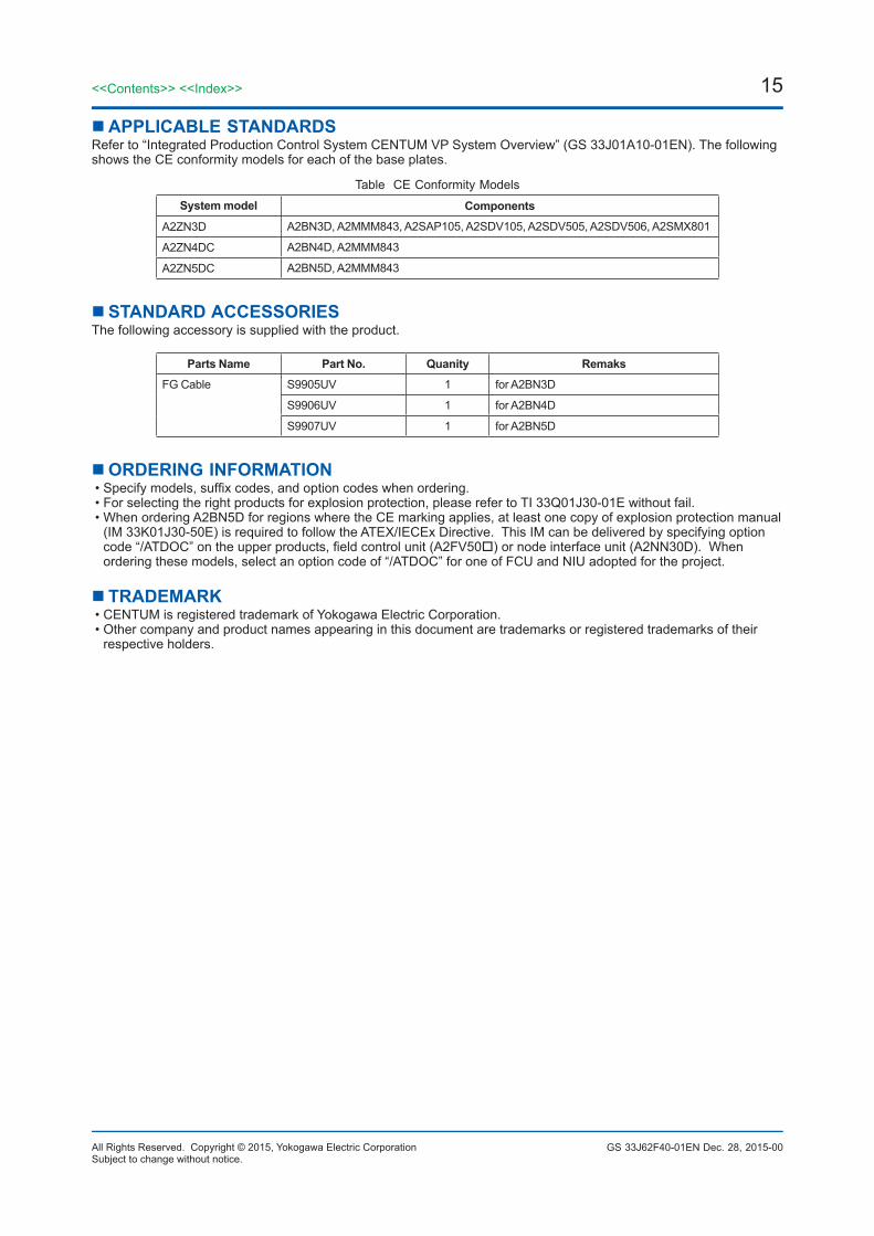
nAPPLICABLE STANDARDSRefer to “Integrated Production Control System CENTUM VP System Overview” (GS 33J01A10-01EN). The following shows the CE conformity models for each of the base plates.
Table CE Conformity ModelsSystem model Components
A2ZN3D A2BN3D, A2MMM843, A2SAP105, A2SDV105, A2SDV505, A2SDV506, A2SMX801
A2ZN4DC A2BN4D, A2MMM843
A2ZN5DC A2BN5D, A2MMM843
nSTANDARD ACCESSORIESThe following accessory is supplied with the product.
Parts Name Part No. Quanity Remaks
FG Cable S9905UV 1 for A2BN3D
S9906UV 1 for A2BN4D
S9907UV 1 for A2BN5D
nORDERING INFORMATION• Specify models, suffix codes, and option codes when ordering.• For selecting the right products for explosion protection, please refer to TI 33Q01J30-01E without fail.• When ordering A2BN5D for regions where the CE marking applies, at least one copy of explosion protection manual
(IM 33K01J30-50E) is required to follow the ATEX/IECEx Directive. This IM can be delivered by specifying option code “/ATDOC” on the upper products, field control unit (A2FV50) or node interface unit (A2NN30D). When ordering these models, select an option code of “/ATDOC” for one of FCU and NIU adopted for the project.
nTRADEMARK• CENTUM is registered trademark of Yokogawa Electric Corporation.• Other company and product names appearing in this document are trademarks or registered trademarks of their
respective holders.
Dec. 28, 2015-00